research m emoran dum
TRANSCRIPT
RESEARCH M EMORAN DUM
EFFECT OF METHOD O F POSITIONING THE RADAR
ANTENNA ON THE SPEED OF RESPONSE
By Marvin Abramovitz
Ames Aeronautical Laboratory Moffett Field, Calif.
w 0 [L
v) t 0
- n
NATIONAL ADVISORY COMMITTEE FOR AERONAUTICS
WASH! NGTON

1R
em m m m m m m m m m m m m m m m m m m m m m m m m m m m m m m m m e m m e m m m m m m m m m m m m m m m m
m m m m m o m . m m m m m m m m m m m o o m m m m m m m m CON Om. F, f,midmf,kL m m m m m m m m m m
NACA FM A52E27 SECURITY INFORMATION
TABU OF CONTENTS
Page
SUMMARY...... . . . . . . . . . . . . . . . . . . . . . . . . 1
INTRODUCTION . . . . . . . . . . . . . . . . . . . . . . . . . . . 2
NOTATION . . . . . . . . . . . . . . . . . . . . . . . . . . . . . 3
DESCRIPTION OF GUIDABCE AM) CONTROL SYSTEMS . . . . . . . . . . . . . 5
-
Guidance Systems . . . . . . . . . . . . . . . . . . . . . . . 5
S y s t e m U . . . . . . . . . . . . . . . . . . . . . . . . 6
S y s t e m I B . . . . . . . . . . . . . . . . . . . . . . . . 7
S y s t e m 1 1 . . . . . . . . . . . . . . . . . . . . . . . . 0
Transfer Functions of Guidance Components . . . . . . . . . . 8
Radarreceiver . . . . . . . . . . . . . . . . . . . . . 9
Antenna servo and antenna-gyro precessor . . . . . . . . 9
Rategyro . . . . . . . . . . . . . . . . . . . . . . . . 9
Control Systems . . . . . . . . . . . . . . . . . . . . . . . 9
N o feedback. . . . . . . . . . . . . . . . . . . . . . . 9
Rate feedback . . . . . . . . . . . . . . . . . . . . . . 10
Displacement feedback . . . . . . . . . . . . . . . . . . 10
Transfer Functions of Missile and Control-System Components . 10
M i s s i l e . . . . . . . . . . . . . . . . . . . . . . . . . 11
Control servo . . . . . . . . . . . . . . . . . . . . . . 12
R a t e g y r o . . . . . . . . . . . . . . . . . . . . . . . . 12
Displacement gyro . . . . . . . . . . . . . . . . . . . . 12
SECURITY INFORMATION

erne e m e e eem e e e e e e e e e e e e b e e .. e . . e . . . . . . e e * e e m e o e e e e . . . . . . . . . . . . . . . . e m e o e m e . . . . * e m e meee e e m e - e .......... ....................... CONFIDENTIAL
SECURITY INFORMATION NACA RM A52E27
TABLE OF CONTENTS . Continued
Page . METHOD AND CONDITIONS OF ANALYSIS . . . . . . . . . . . . . . . . . 12
RESULTS AND DISCUSSION . . . . . . . . . . . . . . . . . . . . . . 14
Effect of Method of Posi t ioning the Radar Antenna on the Speed of Response . . . . . . . . . . . . . . . . . . 1 4
SystemIA . . . . . . . . . . . . . . . . . . . . . . . . 14
SystemIB . . . . . . . . . . . . . . . . . . . . . . . . 14
System11 . . . . . . . . . . . . . . . . . . . . . . . . 14
Effect of Mach Number on the Response . . . . . . . . . . . . 15
s y s t a u . . . . . . . . . . . . . . . . . . . . . . . . 15
SystemIB . . . . . . . . . . . . . . . . . . . . . . . . 15
System11 . . . . . . . . . . . . . . . . . . . . . . . . 15
Effect of Networks . . . . . . . . . . . . . . . . . . . . . . 15
SystemIA . . . . . . . . . . . . . . . . . . . . . . . . 15
S y s t e m m . . . . . . . . . . . . . . . . . . . . . . . . 16
CONCLUSIONS . . . . . . . . . . . . . . . . . . . . . . . . . . . . 18
APPENDIX A . GUIDANCE-SYSTEM TRANSFER FUNCTIONS . . . . . . . . . . 19
APPENDIX B . CONTROL-SYSTEM TRA.NSFm FUNCTIONS . . . . . . . . . . 21
REFERENCES . . . . . . . . . . . . . . . . . . . . . . . . . . . . 23
TABUS . . . . . . . . . . . . . . . . . . . . . . . . . . . . . . 24
FIGURES . . . . . . . . . . . . . . . . . . . . . . . . . . . . . . 27
.......... ....................... e emme . . . . . . ......... ...... ............ . . . . . . . e m . . e m . . . . : c & < m h t ........ ?!kCmM If#b@$$ION

m m m m m m m m m m m m m m m m m o m
m m e o m m m m m m m m m m m m m m m m m m m m m m
m m m m mo m m m m m m m m m m m m m m m m
m m m m m m m m m m m m m m o m m m m m m m m
m m m m m m m m m m
NACA RM A52E27 CONFIDENTIAL SECURITY INFORMATION
NATIONAL ADVISORY COMMITTEE FOR AEXONAUTICS
RESEARCH MEMORANDUM
THE(EETICAL INVESTIGATION OF THE PERF(IRMANcE OF
PROPORTIONAL NAVIGATION GUIDANCE SYS- - EFFECT OF MGTHOD OF P O S I T I O N I N G TEE RADAR
A " A ON THE SPEED OF R3SPONSE
By Marvin Abramovitz
SUMMARY
A l i nea r theore t ica l analysis has been made of the performance of three proportional navigation guidance systems ins ta l led i n a given supersonic, variable-incidence, boost-glide, a n t i a i r c r a f t missile a t Mach numbers of 2.7 ( the nominal design value) and 1.3. These guidance systems, which d i f f e r i n the method of posit ioning the radar antenna r e l a t i v e t o a coordinate system fixed i n space, a re compared on a basis of the maximum obtainable speed of response of the missi le and guidance- system combination consistent with adequate s t a b i l i t y .
It i s shown tha t , with the antenna s tab i l ized i n space, the e f f ec t o f component lags on the response i s s m a l l , so t ha t the speed of response can be made t o approach closely that of the airframe alone.
Conversely, if the antenna i s n o t s tabi l ized i n space, the obtain- able speed of response i s limited by s t a b i l i t y considerations of the missi le and guidance-system combination. works, it is possible t o obtain performance comparable t o t h a t of the system with the antenna s tabi l ized. sens i t ive t o s m a l l var ia t ions i n network time constants and t o missi le flight-speed variations. Therefore, unless care is taken i n select ing gearings and network time constants, i n s t a b i l i t y i s l i ke ly t o occur due t o the missile speed decrease during the glide phase.
By including compensating net-
However, the response i s re la t ive ly

2 C ONTIDENT IAL SECURITY INFORMATION
NACA RM A52E27
INTRODUCTION
It is generally recognized that guiding an antiaircraft homing missile along a proportional navigation trajectory offers certain impor- tant advantages, the principal one being the low missile acceleration required during the terminal portion of the trajectory (see, for instance, references 1 and 2). a missile rate of turn proportional to the rate of rotation in space of the line of sight between the missile and the target. system is composed of a seeker, which measures the rate of rotation of the line of sight, and a control system, which produces a missile rate of turn proportional to the seeker output. Most systems use a movable radar antenna in the seeker to track the target and measure the rotation of the line of sight in space.
A proportional navigation guidance system produces
The guidance
Various methods of positioning and stabilizing the antenna in space have been proposed and numerous isolated system studies have been made of these methods in conjunction with specific missile airframes and control systems. However, it was considered desirable to investigate on a common basis several types of proportional navigation guidance systems in com- bination with a given supersonic missile configuration. An investigation of this type should permit a more direct comparison of the system charac- teristics than do the isolated system studies and should lead to a better understanding of the relative importance and interrelation of the various guidance-system parameters.
For this investigation, three proportional navigation guidance systems were selected which differ in method of positioning and stabiliz- ing the radar antenna in space. In one system the antenna and missile rotations are directly coupled and the antenna is not stabilized in space. In the second system the antenna and missile rotations are coupled, but an attempt is made to space stabilize the antenna by rotating it with respect to the missile an equal and ornosite amount to the missile yawing motion. In the third system no coupling between the antenna and missile is present, since the antenna is stabllized in space by mounting it with a free g y r o . The systems were investigated in combination with a cruci- form, variable-incidence-wing missile configuration similar to one for which extensive measured and estimated aerodynamic data are available.
In the selection of a guidance system, a wide variety of character- istics must be considered, such as the size, weight, and reliability of the various components; the effects of nonlinearities and spurious inputs, such as radar noise; and the ability to correct quickly for launching errors and follow closely target maneuvers. The present investigation has been confined to this latter ability. Linearized kinematic studies have indicated that the miss distance due to launching errors and target maneu- vers is a dl;r,$c4mf51qr.tion ~ ~ . t h e e ~ e o ~ - ~ l ~ o o ~ ~ e ~ tl@ sag (Ykference 2).
e e m e m . m e . * . e m
o m . e *
0 . . e e .
e . ... .a. e * *
co&&;Al: e... *.e om..
SECURITY INFORMATION
L

COmFIDENTIAL SECURITY INFORMATION
3
With zero lag no miss distance occurred. Thus, it appeared reasonable to judge the system performance on the basis of the system time lag or speed of response. Accordingly, the missile transient response to a step in the rate of rotation of the line of sight was examined by means of an electronic analog computer. The speed of response and stability are, in a qualitative sense, immediately apparent from the transient response. The optimum responses were determined by varying the parameters of simpli- fied versions of the three guidance systems for the missile at a nominal homing Mach number of 2.7.
Since most air-to-air antiaircraft missiles are of the boost-glide type with guidance in the glide phase only, some consideration must be given to the change in system characteristics with decreasing flight speed. The relative sensitivity of the systems to changes in flight speed therefore was determined by examining the transient response at a Mach number of 1 . 3 with the optimized guidance parameters as determined at the higher Mach number. networks added to the systems having the poorer responses in an attempt to improve them.
The above procedure was repeated with shaping
A s noted above, this investigation is confined to a study of the maximum obtainable speed of response which, to a large extent, determines the magnitude of the miss distance due to target maneuvers and launching errors. miss distance is radar noise in the form of target glint or scintillation. In general, the effect of noise is very important and should be the sub-
Another factor that can contribute significantly to the total
' ject of further investigation.
NOTATION
c,c transfer-function coefficients
f,F shorthand notation for numerator and denominator, respectively, of transfer f'unction with constant term equal to unity
moment of inertia in pitch or yaw, slug-feet squared =Y K transfer-function gearing
L lift or side force, pounds
M pitching moment or yawing moment, pound-feet (or Mach number)
SECURITY INFORMATION
e e. e e . e e . e e . e . . . . e e . * e . e
e e e.. e e.. a e. e. e e e e e e e e e 0 e... e . e . e . e e . e . .
e.. e... e.. e e.. e.. e.. e e e... e.. e 0 e.
e.. e... e.. . * e * e.. e.. e.. e. e
4
N
CONFIDENTIAL SECURITY INFORMATION
($)steady state navigation ratio
NACA RM A523327
a variable introduced in the Laplace transformation
transfer-f’unction time constant, seconds
flight speed, feet per second
voltage V
angle of attack or sideslip, radians U
flight-path angle, radians 7
6 control deflection, radians
radar-antenna error angle, radians
5 damping ratio
e angle of pitch or yaw, radians
x angular orientation of radar-antenna axis with respect to missile longitudinal axis, radians
(5 line of sight angle in space, radians
on undamped natural frequency, radians per second
Sub scripts
A antenna servo in systems IA and IB, or antenna gyro-precessing mechanism in system I1
f feed-back gyro in missile control system
G rate gyro
integrator
missile-control-system-combination transfer function
network
I
m
N
R
L

WCA RM A52F27 CONFIDENTIAL SECURITY INFORHATION
control servo
(0 missi le t ransfer function
DESCRIPTION OF GUIDANCE AND CONTROL SYSTEMS
Guidance Systems
A proportional navigation t ra jec tory i s obtained when
?/; = N
The r a t i o of the missi le rate of turn t o the rate of ro ta t ion the l i n e of s ight , N, is a constant greater than un i ty and is the navigation r a t io . It can be appreciated that; t o provide
5
i n space of defined as proportional
navigation, a guidance system must perfom two functions: determine the r a t e of ro ta t ion of the l i n e of s ight and develop a missi le r a t e of turn proportional t o t h i s quantity. It was s ta ted e a r l i e r t h a t most propor- t i o n a l navigation guidance systems use a tracking radar with a movable antenna t o measure the rate of rotat ion of the l i n e of sight. de tec ts
The antenna E, the angle between t h e l ine of s igh t and the antenna axis, and
the r a d a r receiver-produces an output voltage, VR, angle
VR =
Due t o the geometric space-angle relationship, t he space ( e + A), the l i n e of s igh t angle ci and the by the following equation ( f ig . 1):
E: = u - ( e + x )
proportional t o t h i s
antenna pos i t ion i n angle E: a r e re la ted
(3 )

6
L
CONFIDENTIAL NACA RM A52E27 SECURITY INFORMATION
it can be shown from the solution of equations (2), ( 3 ) , and (4) that
( 5 ) V R - 1/K . - a 1 i- (1hR)P
Thus the radar-voltage output is proportional to the rate of rotation of the line of sight but with a time lag inversely proportional to the seeker gearing, KKR. With large values of this gearing, the lag is small and the antenna closely tracks the target.
In practice, it is not possible to control the antenna exactly as The three methods of antenna indicated by the idealized equation (4).
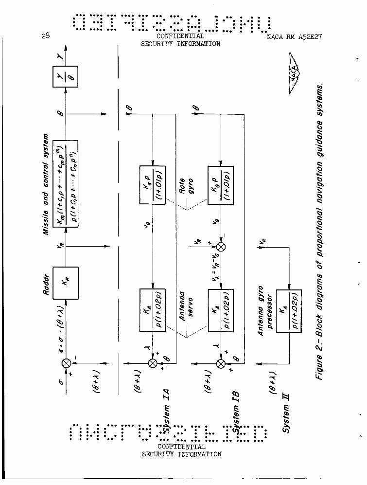
positioning dealt with in this report can be represented in principle by equation (4), but because of the time lags in the various components significant differences in the over-all dynamic characteristics may occur. Figure 2 is a block diagram of the guidance systems. The upper portion, containing the radar receiver and missile-control-system combination, is common to all three systems while the lower portions, which indicate the method of positioning the radar antenna in space (i.e., forming 8 + A), are drawn separated from the upper portion to emphasize the differences. The following paragraphs describe the operation and characteristics of the guidance systems in supplying the missile control system wi:h a sig- nal proportional to the rate of rotation of the line of sight 6:
System IA.- In this system, the antenna is not stabilized in space. It is positioned with respect to the missile by the antenna servo, which responds primarily at a rate proportional to the rate-gyro output. The antenna position depends on the radar-receiver output in an indirect manner, since the rate-gyro output is proportional to the radar output, but modified by the dynamics of the missile-control-system combination. The antenna motion, then, is directly coupled to the missile body rota- tion for this system.
The missile-control-system combination, which will be described later, can take many forms. of turn, f, proportional to the radar-voltage output, q.
It is only necessary that it produce a rate
The closed-loop transfer f’unction, derived in appendix A, is:
- = i FAFGFf fy 7
where I
SECURITY INFORMATION

2R
0 0 0.0 0.0 0 0 0 00.0 0 0 0 00.0 0.0 0 0 0 0 0 0 0 . 0 .
0 0 0 0 0 0 0 0 0.0 0 0.0 0 0 0 0 0 . 0 0 . 0 .
0 0 0 0 0. 0 0 0 . 0 0 . 0 0 0 0 . 0 0 . 0 0 0 0 0 0.00
0.0 0.00 0.0 0. 0 0 0.0 0.00 0 0 0 0 0 0 0 0 0 0 0 0
NACA RM A52E27 C O N F I D r n I A L SECURITY INFORMATION
7
The navigation r a t i o is determined by the value of the feed-back gearing, QQ, while the forward gearing, ~ K R , e f fec ts only the dynamics. For a fixed navigation r a t i o and specified component time constants, it is only necessary t o vary one parameter i n determining the optimum response. Note t h a t the block diagrams of appendix A and figure 2 d i f f e r i n the sign of the feed-back quantity f o r t h i s system. For navigation r a t i o s greater than 1, KAKG must be posi t ive and l e s s than 1 fo r the system as shown i n the appendix, and negative with an absolute value less than 1 f o r the system as shown i n f igure 2.
System IB.- I n t h i s system, an attempt i s made t o s t a b i l i z e the antenna i n space. integrat ing antenna servo, which essent ia l ly responds at a rate propor- t i o n a l t o the radar-receiver output. The antenna posi t ion i n space (e + A ) , t h a t is, the antenna posit ion with respect t o the a rb i t r a ry referenceaxis , i s the resu l tan t of both the antenna-servo motion and the missile-body rotat ion. The rate-gyro output i s subtracted from the radar output t o form the input t o the antenna servo i n order t o s t a b i l i z e the antenna i n space, t h a t is, t o separate the antenna posi t ion from the missile-yawing motion. With un i ty gearings and zero time lags i n the antenna servo and rate gyro, this would be accomplished exactly, since the 6 However, i n the p rac t i ca l case, some l ags do occur i n these components so t h a t t he antenna cannot be exactly s tabi l ized i n space and some degree of coupling does e x i s t between the antenna motion and the missile-body ro ta t ion .
It is positioned with respect t o the missile by the
feedback would be canceled a t the adder at which ( 6 + A) is formed.
The closed-loop t ransfer f’unction f o r t h i s complete system i s (see appendix A f o r derivation)
I
I i. FAFGFf f 7
where (7) i It can be seen that, with fixed values f o r the control system and guidance- component t h e constants, the response depends on three groups of gearings: &/KA; KAQ, the antenna s t ab i l i za t ion gearing; and open-loop gearing. For a given navigation r a t i o N, the gearings I(in/lQ and KAKG are in te r re la ted . The gearing QK,R is independent of N and a f f e c t s only the dynamics. I n optimizing the response a t a fixed naviga- t i on r a t io , then, only two parameters, K& must be considered.
K$$, the seeker
and e i the r Km/KA or KAgG,
SECURITY INFORMATION

......................... . . . . . . . 8
.......... ....................... CONFIDENTIAL NACA RM A52E27
SECURITY INFORMATION
System 11.- I n t h i s system, the antenna i s s tab i l ized i n space by mounting it on a f r e e gyro. The antenna i s positioned i n space by pre- cessing the gyro a t a r a t e proportional t o the radar output voltage and i ts posit ion i s independent of the missile-body rotat ion. The t ransfer function f o r t h i s system i s
(8) I - 7 = (h/KA)FAFffr (1 + PFA/uKR)Fm
where
h / K A = N
Thus, the gearing IQ/KA i s apparent t h a t a large value of t he seeker gearing t o hold the over-all system lag t o a minimum.
i s fixed f o r a given navigation r a t io , and it KAKR i s desirable
It can be seen t h a t the charac te r i s t ics of the three systems described above d i f f e r primarily i n the degree of coupling between the antenna and the missile-body angular motions. In system I1 the antenna i s completely f r e e of the missi le yawing motion except f o r any f r i c t i o n t h a t might e x i s t i n the gimbal pivots, an e f f ec t neglected herein. system I B the degree of coupling depends on the time lags and gearings of the antenna servo and r a t e gyro, while i n system LA the antenna pos i t ion and missile dynamics a r e d i r e c t l y coupled.
I n
Transfer Functions of Guidance Components
The assumptions made i n expressing the t ransfer functions of the various components of the guidance systems which appear i n f igure 2 w i l l now be described. The charac te r i s t ics of dynamic elements such as those used i n these systems can usual ly be represented t o high accuracy by a second-order t ransfer function, containing a gearing, a natural frequency, and a damping r a t io , as i n the following equation:
Moreover, the second-order term can of ten be neglected and the resu l t ing f i rs t -order t ransfer function, containing a gearing and a' time constant or lag, w i l l s t i l l represent the dynamic charac te r i s t ics adequately over a frequency range from zero t o a value which depends on the component na tura l frequency and damping r a t io . for most of the components of the systems of t h i s report , since t h e i r na tura l frequencies a re much higher than the missi le sGorbperiod na tura l frequency ...$ ol; .$Taf t $ e p n p w t e f l 'thD h'$$u%1: f$-$p$ncy i s high
This approximation has been used
: ............. ': . :. ...... . 0 . . 0 .
C ; ~ & G L 0 . 0 . * . ...................
I
I SECURITY INFORMATION ,
"

.
NACA RM A52E27 COITFIDENTIAL SECURITY INFORMATION
enough so tha t the f i r s t -order term i s a l so neglected since it i s small i n comparison with the f i r s t -order terms of the other components.
Radar receiver.- It was assumed t h a t the radar receiver responds instantaneously with an output voltage proportional t o the e r ro r angle, so t h a t the t ransfer f‘unction becomes
9
Antenna servo and antenna-gyro precessor.- A s m a l l , high-performance in tegra t ing antenna servo was assumed f o r systems IA and IB. sponding un i t i n system I1 is the antenna-gyro precessing mechanism. Ident ica l charac te r i s t ics were assumed f o r both, a na tura l frequency of 10 cycles per second and a damping r a t i o of 0.7, which r e s u l t s i n the following approximate f i r s t -order t ransfer f’unction:
The corre-
R a t e gyro.- A na tura l frequency of 20 cps and a 0.7 damping r a t i o was assumed, resu l t ing i n an equivalent f i r s t -order time l a g of approxi- mately 0.01. The t r ans fe r function i s
K$ V G = 6 1 + 0.01p
Control Systems
The purpose of the missi le control system i s t o produce a missi le r a t e of turn proportional t o the radar output voltage. over-all guidance system response depends t o some extent on the type of control system, t h i s report i s concerned ch ief ly with antenna posit ioning methods, and control systems were not investigated i n great de t a i l . The following paragraphs b r i e f l y describe the charac te r i s t ics of the control systems considered. Block diagrams of these systems, including the m i s - s i l e , a r e shown i n f igure 3 and the derivation of the t r ans fe r functions and a more complete discussion a re included i n appendix B.
Although the
No feedback ( f ig . 3(a)).- I n its simplest (and, from a r e l i a b i l i t y standpoint, the most desirable) form, the control system is composed so le ly of a servo linked t o the missile control surface. function i s
The t ransfer
where 1 SECURITY INFORMATION

10
......................... . 0 . . e . . . e . . ........ . . . . . . . . . . . . . . . . ...... 0 . 0 . . e . 0 . . e e .......... ....................... 0 . e . 0 . . .... e .
CONFIDENTIAL NACA RM A52E27 SECURITY INFORMATION
Rate feedback (fig. 3(b)).- This system employs the usual method of feeding back the missile angular velocity to increase the low natural damping of supersonic missile configurations. The lead network at the rate gyro is necessary to compensate for the control-servo time lag (see appendix B). With the proper choice of open-loop gearing, KsQKf, the damping ratio at of 0.054 to a maximum of 0.8 with only a small effect on the natural fre- quency over most of this range. The transfer function is
M = 2.7 can be varied from a missile-alone value
where
Displacement feedback (fig. 3(c)).- This system employs a displace- It is necessary to ment gyro to feed back the missile angular movement.
add the integrator to obtain a missile rate of turn proportional to the radar output voltage for this system (see appendix B). function is
The transfer
where (15)
Km = KdKf
Due to the large value of To, an aerodynamic time constant in fe (see equation (17)) which occurs in the first-order term of the denominator, this system introduces a large lag into the over-all response. Although it is possible to compensate for this lag, the stability would be very '
sensitive to changes in the missile flight speed (see appendix B). Further investigation disclosed that reversing the sign of for only system IA. system in combination with system IA.
Kf ( i. e., vs = vI -t. vf) had a beneficla: effect on the speed of response of
Results are presented therefore only for this control
Transfer Functions of Missile and Control-System Components
In the following paragraphs the simplifying assumptions made in arriving at the transfer functions of the components of the control systems, including the missile, will be discussed.
.......... ....................... . . e . . . . . . . . . . . . . . . . e . 0 . . ...... e * 0 . 0 . 0 . . ........ ................. 0ef)i-E- . . . . . . . .... . . . . . . . c
SECURITY INFORMATION

NACA RM A52E27 CONFIDENTIAL SECURITY INFORMATION
11
cruci with
Missile.- The missile is a supersonic, variable-incidence wing, .form configuration. 60° vertex angles and the tails are interdigitated 45O.
The wings and tails are of triangular plan form
figuration is the sane as the variable-incidence configuration studied in reference 3. The aerodynamic characteristics, derived in reference 3 from tests of a similar configuration, were used in the present study. It is assumed that a perfect roll-stabilization system is provided. a symmetrical configuration such as this the lateral and longitudinal equations of motion are identical, if the effect of gravity is neglected. The common practice of neglecting this effect has been followed in the present study, and the familiar longitudinal equations of motion are used. Neglecting changes in the forward speed, these equations are
This con-
For
(16) i (L, + mm)a - mme = -I,@
- &,D)u + (-GD + IyD2)e = MsS
e - a = y
The following transfer functions, which appear in the guidance- and control-system block diagrams, can be derived from the above equations:
where
% = J-m- mvIY -
.
SECURITY INFORMATION

......................... . 0 . . 0 -
12 CONFIDFINTIAL NACA RM A52E27 SECURITY INFORMATION
Val-ues of these aerodynamic derivatives and missile transfer-function coefficients for an altitude of 50,000 feet and Mach numbers of 1.3 and 2.7 are listed in table I.
Control servo.- The control servo is approximated by a first-order time lag of 0.05 second, which corresponds to a second-order system having a damping ratio of 0.7 and a natural 'frequency of about 5 cps. The transfer function is
Rate gyro.- The characteristics of the rate gyro in the rate feed- back control system are assumed identical to those of the rate gyro in the guidance loop. However, the geaYing is designated by Kf and a lead network with a lead constant equal to the control servo lag is added. It is assumed that a relatively small lag is introduced by the network and this term as w e l l as the second-order gyro t e r m is neglected. The trans- fer function, therefore, becomes
Displacement gyro.- It is assumed that the displacement gyro in the displacement feed-back control system introduces no dynamic effects so that its transfer f'unction ia
Vf e - = Kf
Integrator.- A 0.01-second lag is assumed for the integrator, so that its transfer function is
METHOD AND CONDITIONS OF ANALYSIS
Several methods of determining the stability and response character- However, some istics of closed-loop systems are available (reference 4).
of these become overly complicated when applied to the example systems which have multiple loops and dynamic elements in the feed-back paths. Hence, transient responses to a step input were obtained directly, using an electronic analog computer.
5
In order to provide a consistent basis of comparison, the system Parsmetera,TdeFe.ELQiUsteb a0 .that) .+d! ~$ggLkTB?; . tfik8 ds.'a' $0-percent
e . . . . . . . . . . . . . . . . . 0 . 0 . . . 0 . . 0 . . ........
0 . 0 . 0 . . . . . . . . ....................... CONFIDEN& SECURITY INFORMATION

C O N F I D r n I A L SECURITY INFORMATION
13
initial overshoot in the 9 output response. For a second-order system this criterion results in a reasonable compromise between the stability and speed of response. For higher-order systems such as those of this investigation, this criterion also applies as a first approximation, if there is one predominant oscillatorymode.
Most of the results of this investigation are in the form of "opti- mized" transient responses. These were obtained by varying the gearings of the guidance and control systems t o determine the most rapid response consistent with the 30-percent overshoot requirement. results of a simplified trajectory analysis (reference 2), the miss dis- tance due to launching errors and target maneuvers depends directly on the system speed of response or time lag.' Therefore, a comparison of the speed of response obtainable with the three high-order systems inves- tigated in this report should indicate their relative merit in counter- acting launching errors and target maneuvers.
According to the
A navigation ratio of three was selected and held constant through- out this investigation. This value was considered a reasonable compromise between higher ratios, which minimize the miss due to launching errors and target maneuvers, and lower ratios which reduce the effects of noise.
The calculations were performed for Mach numbers of 2.7 and 1.3 at an altitude of 50,000 feet. this type of boost-glide missile, and the high altitude was chosen as being critical in terms of missile maneuvering capabilities. sient responses presented for a Mach number of 2.7 (considered the nomirial design speed) are the optimized responses as described above. responses at a Mach number of 1 . 3 (considered an extreme off-design speed) are for the optimized gearings, as determined at the Mach number of 2.7.
This Mach number range is representative for
The tran-
The
The results include the three guidance systems of figure 2 in com-
The displacement feed- Results also include
bination with the control system having no feedback and rate feedback (figs. 3(a) and 3(b)) for the above conditions. back control system is used only with system IA. the effect of networks on systems IA and IB with the rate feed-back con- trol system for the nominal design speed condition.
lIn this type of analysis the complete guidance- and control-system dynamics are approximated by a first-order transfer function and the kinematic equations are linearized. nondimensionalized miss distance, indicates that, with other quantities held constant, the miss distance is directly proportional to the system time Lag, in the absence of noise. ered, however, some amount of lag is desirable. The necessary lag, which depends on the noise characteristics, can be provided by a filter or by decreasing the system internal gearings to obtain a more sluggish
The solution, in the form of a
When a noise input is also consid-
SECURITY INFORMATION

14
......................... 0 0 . 0 0 . . . . . . . 0 . 0 . . ........ . . . . . . . . . . . . . . . . . .......... ....................... . . ...... 0 . 0 . . . .... 0 . 0 . 0 . .
CONFIDENTIAL NACA RM A52E27 SECURITY INFORMATION
RESULTS AND DISCUSSION
Effect of Method of Posit ioning the Radar Antenna on the Speed of Response
Figure 4 presents the optimized-responses, as defined i n the previous Included are the r e s u l t s f o r the three section, for a Mach number of 2.7.
guidance systems of f igure 2 i n combination with the appropriate missile- control systems of f igure 3. gearings are l i s t e d i n tab le 11.
The corresponding values of t he optimum
System IA (fig. 4(a)).- With e i the r r a t e feedback o r no feedback i n the control system, the response f o r t h i s guidance system is very slug- gish. If the gearing KRK& i n i t i a l overshoot, the high frequency osc i l l a t ion becomes unstable i n both cases. With displacement feedback, the response is grea t ly improved. Note i n table I1 t h a t f o r t h i s case Kf i n f i g . 3), so t ha t the control system i t s e l f i s unstable. conventional displacement feedback ( i .e . , with it w a s found t h a t no Fmprovement i n the response could be obtained.
A very s m a l l high-frequency damped osc i l l a t ion i s excited i n i t i a l l y . i s increased i n an attempt t o achieve a 30-percent
is negative ( i . e . , vs = VI + vf Results f o r a
K f > 0) a re not shown, as
System I B ( f ig . 4(b)).- The optimized response f o r t h i s system i s ra ther slow, with a r i s e time of about 0.7 second. If QKR i s increased i n an attempt t o increase the speed of response, t he i n i t i a l high-frequency osc i l la t ion becomes unstable. For values of la rger than the opt i - mum, the readi ly discernible longer period osc i l l a t ion becomes unstable. The higher damping furnished by the r a t e feed-back control system e f fec t s primarily the high-frequency osc i l la t ion . However, since t h i s o sc i l l a - t i o n i s of such small amplitude compared t o the over-all response, very l i t t l e change i n the speed of response i s apparent.
System I1 ( f ig . 4(c)) . - This system, with a s tab i l ized antenna, has the most rapid response, with a frequency very nearly t h a t of the a'irframe alone ( w 12rad/sec). The r a t e feed-back control systen increases the damping t o some extent, but it i s not possible t o obtain good damping and s t i l l maintain 30-percent overshoot. system gearing, the damping can be increased but t he overshoot decreases as i s shown i n the f igure. indicated t h a t t h i s i s a charac te r i s t ic of the variable-incidence missi le configuration.
By increasing the open-loop control-
Further investigation of t h i s system has
The r e su l t s of t h i s section indicate c l ea r ly the l imitat ions on the maximum speed of response obtainable when the antenna i s not s tab i l ized i n space (systems IA and IB). The range of usable gearings i s l imited due t o s t a b i l i t y considerations so t h a t it is not possible t o increase the spee4.qf.re8BXase % ?d$sicapk Tp&e:*:Wtt& we:a,&hna s tab i l ized
0 . . . . . . . . . . . . . . . . . 0 0 . . . . . . . . ........ . 0 . . 0 . 0 . . 0 . 0 . 0 . .................... c O~#IDE&AL
SECURITY INFORMATION

I O * . 0 0 0 0 0 ooe 0 0 0 0 0 . 0 0 0 0 0 0 0 0 0 0 0 0 0 0
3R NACA RM A52E27 comIDENTIAL
SECURITY INFORMATION 15
i n space (system 11), the speed of response i s l imited only by the design charac te r i s t ics of the airframe alone.
. .
Effect of Mach Number on the Response
Figure 5 shows the responses a t a Mach number of 1.3 with the same component gearing as f o r the M = 2.7 responses. The missile-control- system gearing m i s s i l e gearing a. Km is, of course, d i f fe ren t due t o the change i n the
System I A ( f i g . ?(a)).- For t h i s system, the responses with no feed- back and r a t e feedback i n the control system have remained s tab le but sluggish. The navigation r a t io , being independent of I&, has remained constant. With the displacement feed-back control system, the response has become v io len t ly unstable.
System I3 ( f ig . 5(b)).- Without feedback the response has become With r a t e feedback, the response i s s t ab le but with poorer unstable.
damping than a t the higher Mach number. f'unction of
The navigation r a t io , being a h, has increased due t o the increase of Q.
.
System I1 ( f ig . >(e)).- For t h i s system, the response has remained s tab le with both control systems. t o the increase i n decreased missi le na tura l frequency.
The navigation r a t i o has increased due &, and the frequency has decreased due t o the
The r e su l t s of the previous two sect ions i l l u s t r a t e the d e s i r a b i l i t y of s t ab i l i z ing the antenna i n space. obtained, and the e f f ec t s of the decrease i n the missi le flight speed during the gl ide phase are not serious. A l s o , it should be pointed out t h a t the character of the response f o r t h i s system i s independent of t he navigation r a t i o . For the other two systems, the navigation r a t i o occurs as a fac tor i n the coeff ic ients of the denominator of' the t ransfer €'unction
A more rapid response can be
Effect of Networks
It was shown in the previous sections t h a t a rapid response could not be achieved with the simplified systems i n which the antenna i s not s tab i l ized i n space (systems I A and I B ) . compensating networks t o increase the speed of response of the systems incorporating r a t e feedback i n the control system i s investigated.
I n this'section, t he e f f ec t of

16 CONFIDENTIAL NACA RM A52E27 SECURITY INFORMATION
the desired response is that of the missile-control-system combination alone such as occurred in the case of system 11, then the desired trans- fer function becomes
= WffY Fm
If this equation is substituted for in the system transfer function (equations (A6) and (A7) which include the network in the feed-back path), the network necessary to attain the desired response can be determined by solution of the resulting equation. The solution is
f/i
Retaining only first-order terms and neglecting quantities of small magni- tude in the brackets, and introducing small lags for the two lead factors outside the brackets, the necessary network becomes approximately
1 1 + TGP r 1 +(3/2)TQP = *' 1 +(TG/lO)p 1 1 + Tep
- - 1 + 0.02p 1 + 0.01~ + 1.269~1 1 + 0.002~ 1 + 0.001~ 1 + 0.846~
With this network included, the response was optimized by varying and the largest lead constant. siderably but still was not as good as for system 11. lected in equation (23), the control servo 1pg is the largest. the response further, an additional lead network was added between the radar receiver and missile control system to compensate for the control servo lag. This network is
K&KR The speed of response was increased con-
Of the terms neg- To improve
The improved response for this system with a lead constant of 1.30 is shown in figure 6(a). of 1 . 3 and it is necessary to reduce the lead constant to 1.272 to main- tain stability throughout the Mach number range. reduced lead is also shown in figure 6(a).
However, the system is unstable at a Mach number
The response with the
System 1B.- It was pointed out earlier that the antenna would be stabilized in space for this system if there were no lags in the rate gyro and antenna servo, and if the product of the gearings of these two com-
SECURITY INFORMATION

.
m a a m m m m m maa sama a a a m a m a m a m m a m a m m
a a m a a m a m a . mea a m m a m a a a m m m a
m m a a m a a m m m m m m m a m a
m a m m a a m m a maa m m a m a m 0 m m am. a m a m a m m m maa m m a a
NACA RM A52E27 CONFIDENTIAL SECURITY INFORMATION
17
functions. altered form, is
The system IB transfer f’unctiou, eqsation (7) in a slightly
With no network present,
and, with the conditions stated above,
so that the transfer function becomes
Except for (equation (8) )
FA? this is identical to the system I1 transfer function
This similarity occurs because, with the assumption of no lags and unity gearings, the first group of terms ;In the denominator of the system IB transfer function has been eliminated. A similar result can be obtained if, with Q K G = 1, the network were to introduce leads equal to the lags of the antenna servo and rate gyro, that is,
9 = FAFG FN
The system IB transfer function now becomes identical to that of system 11. Since it is impossible to obtain pure leads as required by equation (q), the following lead networks with lags of one-tenth the lead were used:
The lead has been increased slightlyto compensate for both the antenna- servo and rate-gyro lag plus the lag introduced by the networks. these networks, the transient response (fig. 6(b) ) becomes almost identical to that of system 11, as anticipated. improves the rather poor damping with only a small decrease in the speed of response, as also shown in figure 6(b). the responses at a Mach number of 1 . 3 are stable.
With
A small deerease in the lead terms
As was the case for system 11,
SECURITY INFORMATION
18
a ma a a m a
a m a m m a a a amam a a m a m a
a a a maam a a a amma a a a a a a a a a am m a a
a a a a a a a a a a ma ma a a a m a . a a a
m e a m a m * a m m a m m a
*am amma a a a a a a a mea a * * a a a a a a a a a a a am
CONFIDENTIAL NACA RM A'j2E27 SECURITY INFORMATION
From these results, it is apparent that a rapid response can be achieved with all three of the guidance systems, provided that the neces- sary networks are included in the systems in which coupling occurs between the missile and antenna motions. However, the network lead constants must be carefully adjusted as small variations of these parameters cause large variations in the response. It is generally recognized that the probabil- ity of failure of a guidance system is to a large extent dependent on the degree of complexity of the system and the dependability of the various components. In selecting the optimum system consideration must be given to the relative complexity, dependability, and accuracy of the networks necessary for systems IA and IB, anqof the gyro-precessing mechanism of system 11.
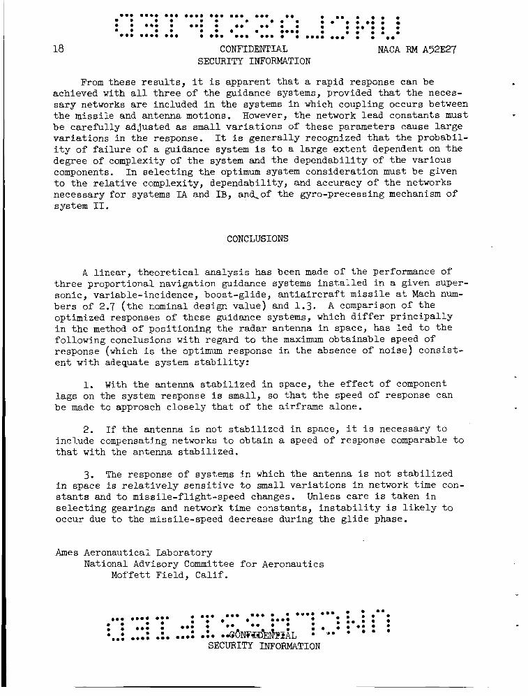
CONCLUSIONS
A linear, theoretical analysis has been made of the performance of three proportional navigation guidance systems installed in a given super- sonic, variable-incidence, boost-glide, antiaircraft missile at Mach num- bers of 2.7 (the nominal design value) and 1.3. optimized responses of these guidance systems, which differ principally in the method of positioning the radar antenna in space, has led to the following conclsions with regard to the maximum obtainable speed of response (which is the optimum response in the absence of noise) consist- ent with adequate system stability:
A comparison of the
1. With the antenna stabilized in space, the effect of component lags on the system response is small, so that the speed of response can be made to approach closely that of the airframe alone,
2. If the antenna is not stabilized in space, it is necessary to include compensating networks to obtain a speed of response comparable to that with the antenna stabilized.
3. The response of systems in which the antenna is not stabilized in space is relatively sensitive to small variations in network time con- stants and to missile-flight-speed changes. Unless care is taken in selecting gearings and network time constants, instability is likely to occur due to the missile-speed decrease during the glide phase.
Ames Aeronautical Laboratory National Advisory Committee for Aeronautics
Moffett Field, Calif.

.
......................... 0 0 . . 0. . ........ . 0 . . ...... 0 ................ . 0 . 0 0 0 00.0 a 0 . 0 0 . 0 . ....................... .......... 0 . 0 . 0 .
NACA RM A52E27 CONFIDENTIAL SECURITY INFORMATION
APPENDIX A
GUIDANCE-SYSTEM TRANSFEEI FUNCTIONS
19
I n the following section, t h e frequency-dependent portion of the t r ans fe r function w i l l be denoted by and the denominator, Fir are of the form (1 + Clp + C z p 2 + ... + Cnp") and the subscript i refers t o the component of the system being con- sidered. For example, the control-system rate-gyro transfer function is
f i / F i where both the numerator, f i ,
This notation i s advantageous i n detewining the closed-loop gearing and the complete-system closed-loop t ransfer function i n a convenient form.
It is a l so convenient t o transform the block diagram of system I B ( f i g . 2) in to the following equivalent form:
The gesrings K1 and K2 and the network fN/FN have been added so t h a t t h i s diagram can represent a l l t h e systems considered i n t h i s report by the proper choice of values fo r these parameters. For the f irst port ion of t h i s report where no networks were considered with K, = K, = 1, the diagram represents system IB; with K1 = 0 and K, = 1, the diagram represents system I A ; and with
f N = FN = 1;
K 1 = 1 and K2 = 0, the diagram rep'r'esehtd sm@l*TI;,,: **e * * a **e a m a m a m *
a m a m a * a m
* * C ~ I D ~ E - * * a a * * * * a * * a * * .*. e . a m
a m e *
a ma a . . . . . . . . . . . . . . . . 0 . * e
SECURITY INFORMATION

20
a a a mama a a a amam a a a a a a a a a am a am a a m a a m a m a m a m a a a m m a m m a a a m a m m a a a a mea a a a a a am am a a
a m a m a a a a amam a a m a m a a a a .earn a a a a a a a a a a a a a a a mama a a a a a am
CONFIDENTIAL NACA RM A52E27 SECURITY INFORMATION
Star t ing from the internal-seeker loop, t he closed-loop t r ans fe r function can be eas i ly derived, using standard servomechanism methods (reference 5),
(A3 1 - KR - ( UKA PAP - - vR a - (e - A,) 1 + K~KAKR/PFA K, + PFA/KAKR
Replacing the seeker loop by i ts closed-loop t r ans fe r function (equa- t i o n ( A 3 ) ) , the compiete system t ransfer function can be readi ly deter- mined
Letting control systems, see appendix B) , and clear ing fract ions,
fm = fgFf (Ff = 1 f o r the displacement feedback and no feed-back
- - i - (h/KA)FAF@f%fr c? (%~/KA)(FAF@N - KAQfN)Fffe + ( K l + pFA/KAKR)FmF@N
where
1 N =
so t h a t
f o r system I A : K, = 0, K2 = 1; K A Q = (y)

. NACA FW A52E27
......................... . ........ 0 . 0 . 0 . . . . . . . . . . . . . . . . . . . . .... . . . 0 . 0 . . ................................. 0 . 0 .
. 0 . . 0 . . 0 . . ...... CONFIDENTIAL
SECURITY INFORMATION
APPENDIX B
CONTROL-SYSTEM TRANSFER FUNCTIONS
21
RATE FEED-BACK SYSTEM
Referring t o figure 3(b), the closed-loop t ransfer function i s
e K s Q f e /pFSFe - = v~ 1 + WWffeff/FsFeFf
! - - KsKeFffe p (FsFeFf + KsKeKfff fe
With no lead network (i.e., with increase i n t h e low missile-damping r a t i o could be obtained with r a t e feedback due t o the rather large control-servo time lag, TS. However, i f f f i s made equal t o Fs, t h i s term becomes a common fac tor of the denominator and the t ransfer function becomes
f f = l), it was found t h a t only a s m a l l
The s t a b i l i t y now depends on only the bracketed quantity which i s equiva- l e n t t o a rate feedback with only the small gyro l a g present. lead constant present, it i s possible t o obtain a maximum damping r a t i o as high as 0.8 a t an open-loop gearing, K s Q K f , of about 0.30. numerator and denominator by the constant term of the denominator gives
With t h i s
Dividing
DISPLACEMENT FEED-BACK SYSTEM

................. 0 . 0 . 0 . . . . . . . . . . . 0 . 0 . 0 . .......... . 0..
22
0.. 0. . 0 . . 0 . . 0 . .a . . . . .... ....... CONFIDENT ILL
. 0 . . 0 . . ........ . ...... a 0 . 0 . . ...........
NACA RM A52E27 SECURITY INFORMATION
For proportional navigation with the systems considered i n t h i s paper, it i s necessary fo r the pi tching ve loc i ty t o be proportional t o the voltage input from the radar i n the steady s t a t e , ra ther than the p i t ch angle as occurs i n equation (B4). For t h i s reason, the in tegra tor w a s introduced and the t ransfer function becomes
I I - - k(1 + SlP) 1 + c,p + C,P2 + CaP3 + C4P4
This system has a slow response due t o the la rge value of To, which occurs i n the f i r s t -o rde r term of t he denominator. A sa t i s fac tory , fast response can be obtained by adding an inner r a t e feedback, o r by in t ro- ducing a gyro l a g equivalent t o To which cancels fe from the denomi- nator . However, it i s d i f f i c u l t t o maintain a sa t i s f ac to ry response throughout the speed range without a var iable gain and gyro t i m e constant due t o the large var ia t ion of To with Mach number. For system I A , it was found t h a t a marked improvement i n the speed of response w a s possible a t M = 2.7 if t he gyro gearing w a s negative. However, due t o the above- mentioned var ia t ion of To with Mach number, the response became unstable a t a Mach number of 1 . 3 .
....................... .......... . 0 . 0 . a .... . 0 . . 0 . 0 . ...... . . . . . . . . . . . . . . . . . ........ . 0 . . 0 . 0 . 0 . . 0 . . 0 . . ......................... CONFIDENTIAL
SECURITY INFORMATION

SECURITY INFORMATION
1. Watkins, Charles E.: Paths of Target-Seeking Missiles in Two Dimen- sions. NACA ACR ~6~06, 1946.
2. Anon.: Integrated Final Technical Report - AN/DPN-7 Guidance System and Associated Equipment. Fairchild Rep. 6~-695, Feb. 19, 1951.
3. Matthews, Howard F., and Stewart, Elwood C.: A Comparison of the Calculated Maximum-Maneuver Response Characteristics of Three Air- to-Air, Beam-Rider, Guided Missiles Having Different Lift Ratios. NACA RM A5lF18, 1951.
4. Jones, Arthur L., and Briggs, Benjamin R.: A Survey of Stability Analysis Techniques for Automatically Controlled Aircraft. NACA TN 2275, 1951.
5. Brown, Gordon S . , and Campbell, Donald P.: Principles of Servo- mechanisms. John Wiley & Sons, Inc., N.Y., 1948.
SECURITY INFORMATION

......................... . 0 . . 0 . . 0 . 0 . 0 . . . . . ........ . . . . . . . . . . . . . . . . . ......
0 . 0 . 0 .... 0 . 0 . 0 . .......... . 0.. ~ ? & i b ~ ? ~ A % * * ' : * * * *<ACA RM A52E27 SECURITY INFORMATION
TABLE I.- MASS AND AERODYNAMIC PARAMETERS OF THE MISSILE AT AN ALTITUDE OF 50,000 FEET
Parameters
La, l b / r ad
Qj, l b / r ad &, f t - l b / r a d
Mk, f t -1b- sec /rad
M i , f t -lb - see / rad %, f t - l b / r a d
m, s l u g 2 Iy' s l u g - f t
Ke, usee 5
V, f t / s e c
To, see
wn, rad/sec
wny, rad/sec 57
M = 2.7
10,300
4,270 -6,800 -6.3 -26.4 2,760
41 6.67
2,620 0 479 0.846 0.0536 12.9
18.1 0.0233
M = 1.3 3,831 1,795 -2,314 -13.6 -27.6 2,030 6.67
1,262 0.614
41
1.422
0.0972 7.54
0.0322 12.7
SECURITY INFORMATION

TABL;E 11.- SYSTEM GEARINGS FOR OPTIMUM RESPONSES AT M = 2.7
No feedback
K A Q = -0.667 ~ K R = 2.16
KAKR = 3.5 K A Q = 1.121 KJyA = 2.2
Rate feedback
With Lead Network
D i sp l ac ement feedback
QQ = -0.667 bQ = -6.84 KSQKf = -0.884

... e... 0.. .... ... ... ... 0 . . 0 . . 0 . . 0 . 0 . 0 . . 0 . . 0 . ..... . . . ... . 0.. . 0 . 0 . . . . ..... . 0 . 0 . 0 . . . .... . 0 . 0 . . ... .... ... . 0.. 0.. 0.. . .... 0. . . . ..
.

27
Figure 1. - Geometric variub/es invo/ved in proportions/ novigation .
. 0 . . 0 . . - - ......................... CONFIDENTIAL
SECURITY INFORMATION
28
. . . . . . 0 . 0 . .......... ......................... 0 . . 0 . . 0 . 0 . 0 . 0 . . ........ . . . . . . . . . . . . a . 0 . . . . .... . 0 . ....................
CONFIDENTIAL
%I I
B
SECURITY INFORMATION
-I-
T
B
-I- $ h
/
'i /
0 . . 0 . . . 0 .
NACA RM A5227
1
c
CONFIDENTIAL SECURITY INFORMATION
6 b ............. .......... ... . . . . . . . ......................... . 3 .... . 0 .
..* +.. 0 0 . 0 . ........ ...... . . 0 9 3 0.. : t o . : q.0 : :
0 . 0 . 0 .

6 5 L- Ks / f .05p
29
Ke /I+ re P/
p z /
@n an P f / + - P + -2 P2/
L
yr Kf / I +.05p/p 4
f / t .o/ p /
Rate gyro and lead network
1
fb) Rate feedback.
U Displocemen?
9YfO
fc) Disp/acement feedback
SECURITY INFORMATION

30
+?ate feedback 4
2
0
- --
......................... . 0 . . 0 . 0 . 0 . 0 . 0 . ........ .......... .... ..... . . ...... . . 0.. a 0.. 0 . 0 . . 0 . 0 . 0 . . . a*.. . 0 . 0 .
*$kA RM A52E27 .c*(jwff&&I~...
--
SECURITY INFORMATION
6
4
2
0
I
feedback I p a t e feedback - P ,
1 .d -- L b+- 4
(a) System I A .
J
6 I I
4 +?ate feedback
I I
D ‘ I
(6) System I B
Time, t, sec
(c) System X.
Figure 4.- Transient responses to o step in 6.
SECURITY INFORMATI ON

5R
I I
......................... ........ . 0 . . 0 . 0 . 0 . ...... ................ 0.0 . 0 . . 0 . 0 .
. 0 . . 0 8 . 0 0 0 . .... .......... "A A5&y ..... :... e o I M G r m
(unsto&/e) rf?ufe fe'edbock
SECURITY INFORMATION
J - c
6
4 r - & 2
0
I 4 -- --- -
e. -- \. No feedbuck
I
/2
/O
8
6
0
-2
-4
(0) System I A .
fb) System 16.
6
4
2
0
r - b
0 .8 /. 6 2.4 4.0 rime, t, sec
fc) System Z.
Figure 5.- Trunsient responses to u step in $. 0 . ....... 0:. M ~ ~ / r ~ ~ f i ~ ~ * f ~ 3 : ~ . : ..... 0 . 0 . .
0 . ...... . . . . . . . . . . . . . . . . 0 . 0 . 0 . . r . ........ ......................... . . . . . . . .
CONFIDENTIAL SECURITY INFORMATION

32
6
2
0
Y
. e * e... e.. e... e.. e.. e.. e. e r e e m e e e . e e . e e . e . . . . e
e e . . . . e e . . e e e e m e e . e . e
.e. eo.. e.. e e.. e.. * - e e e e... * * e e e e *
e . e . e e e.. e e.. e e. e. e e e . e .
NACA RM A52E27 CONFIDENTIAL SECURITY INFORMATION
I I I I 1 I I I I
(u) System I A with rute feedback.
8
6
4
2
0
W
I
0 .8 I. 6 2.4 3.2 4.0
Time, t, sec
(bj System I0 with rate feedbuck.
Figure 6.- €ffect of networks on the transient response. Much number, 2.7.
e * e * m e e e m e e e e e e e e e e e e e e.. e... e.. e e . e . e emme e e . . e . e . e e m e e e e e e e * e. e e.. e e.. e e e m e e e . . e e - e e e m e . e . e e . e e. . e e e e e e e e e e e e e e e m m e e e e e e e e
CONFIDENTIAL SgCURITY INFORMATION
NACA-Langley - 8- 1-52 -350

• •• • • •••• • •••• •• • • • • •• • •• • • •
• •• • • • • • • •••
•••• • • •• • ••••
•••
••• • • • •••
• • • • ••••
• • ••• • ••• f
•• • • • • •••• • •
• •• • • • •••
• •• • •• • • ••
• •• • •• • •••
• ••••• • • •• • . .. ••• • ••
• •• • •• • • ••
• • •••• • • • • ••
~ ... .. . • • ••• • • • • •••
• ••
• ••• • ••• • • •••
••• • • • • • • •••
• • •• • • • • • • • ••• • • • • • • ••
• • • •• • •• • • • • • •

SECURITY INFORMATION ••• •••• • •• . .. .. ••• ••• ••• •• • •• • • • • • • • • • • • • • • • • • • •• • • • • ••• • •••
~O~ F[O E NT.I.AL .. : •• • • • • • • • • • • • • ••• • • •• • • • • • • ••
•• • • ••• • ••• • • ••• ••• ••• • ••• • ••• •• • • • • • • • •••• • • • • • • • • " • • • •• • • • • •• •• • • •• • • •• • • • • •• • • • • • • • • • • • • • • • • • • •• • •• • •• ••• ••• , ... • •• •••• •••
CON FI DENTIAL