r es earch m emoran dum - nasa · 00 -00 0 0 0 0 0 0 copy 0 000 00 rm e54c30 25) / r es earch m...
TRANSCRIPT

0 0 -00 0 0
0 0 0 0 copy # . 0 0 0 0 0 0 RM E54C30
25) /
R ES EARCH M EMORAN DUM -
INVESTIGATION OF E F F E C T OF NUMBER AND WIDTH OF ANNULAR
FLAME-HOLDER GUTTERS ON AFTERBURNER PERFORMANCE
By James G . Henzel , Jr., and Lively Bryant
Lewis F l igh t Propuls ion L a b o r a t o r y Cleveland, Ohio
OTS PRICE L /' ,
/-, .[-f #- ' - .
XEROX $
HlCROFltH $ . / ,' / /'+. /
FOR AERONAUTICS WASHINGTON
JTuJp L , 3 7 q - i : - . - L A
I
https://ntrs.nasa.gov/search.jsp?R=19630006357 2018-09-12T20:01:57+00:00Z

....... 8 . 8 . 8 .om 8 .om 8 . . . . . . . . . . . . . . . . . . . . . . . . . . . . . . . . . . . . . . . . . . . . . . . . . . . ..... ........ NACA RM E54C30
NATIONAL ADVISORY COMMITTEE FOR AERONAUTICS
7NVESTIGATION OF
FLAME-HOLDER
RESEARCH MEMOFUQIDUM
EFFECT OF NUMBER AND WIDTB OF ANNULAR
GUTTEXS ON AF!t'E€BURNER PERFORMANCE . . * '
By James G. Henzel, Jr., and Lively Bryant
SUMMARY
The effect of the number and width of annular flame-holder gutters on afterburner performance was investigated in a 26-inch-diameter after- burner test rig. The burner inlet temperature was held at 1250' F. 1-ring, a 2-ring, and two 3-ring flame holders were investigated over a range of fuel-air ratios from about 0.03 to about 0.10. For these con- ditions, afterburner inlet total pressures varied from about 450 to 1300 pounds per square foot absolute.
A
In general, the combustion efficiency increased as the number of annular gutters increased. A 3-ring, 48-percent blockage flame holder had 15 to 20 percentage points higher efficiency than a 1-ring, 23- percent blockage flame holder for burner inlet total pressures from about 600 to 800 pounds per square foot absolute over a range of fuel- air ratios from 0.05 to 0.07. 1.5 inches or more appeared necessary for good low pressure performance. Below a burner inlet total pressure of about 700 pounds per square foot absolute a 2-ring, 1.5-inch-width V-gutter flame holder was superior to a 3-ring, 0.75-inch-width V-gutter flame holder because of local blow- out of the flame seating on the 0.75-inch V-gutters. The flame seating on the 1.5-inch V-gutters remained bright and steady. If nonburning total-pressure losses in excess of 2 percent are to be avoided, after- burner flame-holder blockages should not exceed about 35 percent for burner inlet velocities greater than 500 feet per second.
In this investigation gutter widths of
INTRODUCTION
Afterburners used for thrust augmentation during certain periods of flight operation require high combustion efficiency over a wide range of pressures and stable combustion over a wide range of fuel-air ratios. Low internal pressure losses are desirable during nonafterburning oper- ation for efficient aircraft cruise. One of the components affecting the performance of an afterburner is the flame holder, which provides

1 the of the fuel-air mixture. was shown to have little influence on both combustion efficiency and stability limits. erence 2, imply that the number of flame-holder gutters might, however, have an important effect on the combustion efficiency. erence 3.it is stated that the number and width of the flame-holder gut- ters influenced the canbustion. efficiency and stability limits, respectively.
sheltered zone necessary for ignition and combustion stabilization I In reference 1, the shape of the flame holder
Studies of flame propagation, such as those in ref-
Also, in ref-
A brief investigation was therefore conducted to determine di- rectly the effects on the combustion efficiency, stability limits, and burner total-pressure loss of the number and width of flame-holder an- nular gutters. The data presented in this report were obtained by op- erating the 26-inch-diameter afterburner of reference 1 in the direct- connect facility. 1250' F. A 1-ring, a 2-ring, and two 3-ring flame holders were inves- tigated over a range of fuel-air ratios from about 0.03 to about 0.10. For these conditions afterburner inlet total pressures varied from about 450 to 1300 pounds per square foot absolute.
The burner inlet temperature was maintained at
APPARATUS
Installation
The general arrangement of the afterburner installation together with a detailed sketch of the burner is shown in figure 1. Combustion air entered the preheater at a temperature of approximately 80' F and was heated to a temperature of 1250° F. The preheater was composed of eight J-35 combustor cans and simulated a primary turbojet engine com- bustor. where it was thoroughly diffused to provide a uniform temperature dis- tribution. A 44 percent solidity screen was placed at the diffuser en- trance to promote a uniform velocity profile of the air passing from the mixing chamber into the diffuser. The diffuser inner body was designed for a constant rate of area increase except at the discharge end, where the rate of change increased because of the rounded-off end of the inner body. The inner body was supported by four streamlined struts 90' apart. The flame holders were placed 7 inches downstream of the end of the inner body and were mounted in an accessible spool piece to facili- tate the installation of the different flame holders. This spool piece contained a quartz window which provided a means of observing the flame front during combustion and of recording blow-outs. The combustion chamber was 25.75 inches in diameter and 48 inches long. The exhaust nozzle was of the convergent-divergent type and had an area ratio (ratio of nozzle throat area to burner cross-sectional area) of 70 percent. The nozzle was designed to remain choked down to an over-all pressure
Upon leaving the preheater the air entered a mixing chamber

....... ............... . . . . . . . . . . . . . . . . . . . . . . . . . . . . . . . . . . . . . . . . . . . . . . . . . . ........
Flame Number
rings holder of
1 1
2 2
3 3
4 3
NACA RM E54C30
Gutter Blockage, width, percent1 in.
2.50 23
1.50 29
1.50 48
.75 29
3
ratio (ratio of nozzle inlet pressure to nozzle exhaust pressure) of 1.25; the divergent section was used to induce choking at the throat under some conditions of marginal exhaust system capacity.
The fuel injection system for this investigation consisted of 24 radial spray bars equally spaced circumferentially and installed in the diffuser section. The fuel was injected 29.5 inches upstream of the flame holder and normal to the direction of the air flow. Each fuel spray bar contained eight orifices, four on each side, which were 0.020- inch in diameter. The arrangement of the bars is shown in figure 2.
Four flame holders were used in this investigation, the details of which are shown in figure 3. annular rings, the gutter widths, and the blockages for each of the flame holders :
The following table lists the number of
lBased on combustion-chamber cross-sectional area.
Ins tmentation
Measurements of pressure and temperature were taken at various sta- tions along the burner, and the table in figure l(b) lists the types and numbers of probes and orifices at each of the measuring stations. specific details of the instrumentation at some of the stations are shown in figure 4.
More
Twenty-five Franz-type thermocouples were located at station 2 in order that the afterburner inlet total temperature could be recorded (fig. 4 w .
At the burner inlet (station 4) 26 total-pressure probes, four stream static probes, and eight wall static orifices were located as shown in figure 4(b). At the burner outlet (station 5) 12 total-pressure

4
e e. e e . e e * * e . .
e e m * e e me. L
NACA RM E54C30
probes in a water-cooled survey rake were located as shown in figure 4(c) , and one wall-static orifice was located at the nozzle outlet (station 7).
PROCEDURE
The air flow was set and maintained constant for a given series of runs by a choked valve in the air supply line upstream of the test fa- cility, as shown in figure l(a). When the air flow had been set, the exhaust nozzle was unchoked, thereby raising the burner-inlet pressure and lowering the inlet velocity. The afterburner was then ignited at a burner fuel-air ratio of approximately 0.050 by use of a torch-type ignitor located ahead of the flame holder, as shown in figure l(b). Once ignftion of the afterburner was completed, the ignitor was turned off and the exhaust nozzle was choked by decreasing the exhaust pres- sure. With the exhaust nozzle choked and the air flow set, runs were made at different fuel flows to vary fuel-air ratio. The fuel-air ratio range covered was from lean blow-out to rich blow-out, or to a fuel-air ratio of about 0.10, whichever occurred first.
Isothermal pressure drops (afterburner inoperative) at different inlet velocities were determined by changing exhaust pressure with an unchoked exhaust nozzle
Stability limits were determined by flame extinction as observed through the quartz window in the wall of the burner. of blow-out, fuel flow and burner exit total pressure were recorded to permit definition of the stability limits and computation of the combustion efficiency at the stability limit. Afterburner air flow (actually air flow plus preheater fuel flow) for a given inlet-air supply valve setting was determined from total-pressure measurements at the burner exit with no burning and with the exhaust nozzle choked. The exhaust nozzle throat area was known, and an assumed flow coeffi- cient was used in the computation.
At the instant
The ratio of afterburner exit to inlet temperature was calculated using the ratio of afterburner exit total pressure with burning to that for nonburning with the nozzle choked, and combustion efficiency was taken as the ratio of actual afterburner temperature rise to the ideal temperature rise at the same fuel-air ratio. was obtained from an ideal temperature rise curve in which dissociation was taken into account. afterburner temperature ratio and combustion efficiency are given in reference 1.
The ideal temperature rise
Computational procedures used in determining

NACA RM E54C30
The fuel u
....... ............... . . . . . . . . . . . . . . . . . . . . . . . . . . . . . . . . . . . . . . . . . . . . . . . . . . 0. 0 . ..........
3 for this investigation was MIL-F-5624A grae JP-4, which had a heating value of 18,725 Btu per pound and a hydrogen-carbon ratio of 0.172.
RESULTS AND DISCUSSION
Inasmuch as this investigation was concerned primarily with the effects of flame-holder geometry on afterburner performance, no changes were made in either the fuel-injection system or diffuser throughout the investigation. give, as nearly as practicable, a uniform fuel-air distribution. Typi- cal fuel-air distributions and diffuser exit velocity profiles may be found in reference 1.
J
1 >
The fuel-injection system was originally designed to
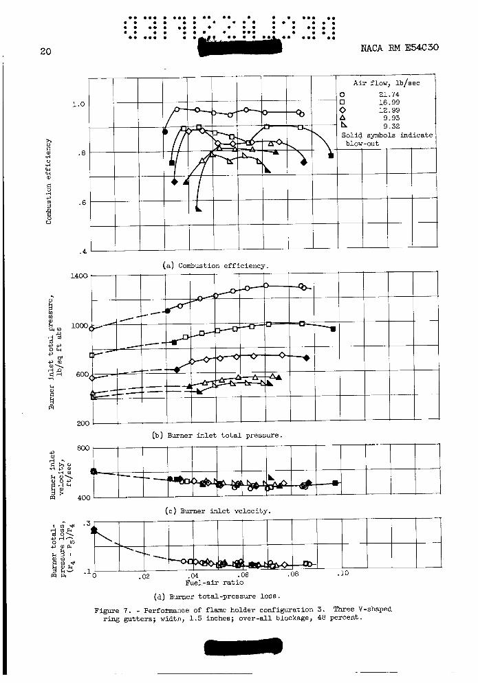
Performance data obtained with the four flame-holder configurations are presented in figures 5 to 8, wherein combustion efficiency, burner inlet total pressure, burner inlet velocity, and burner total-pressure loss are plotted against fuel-air ratio. haust nozzle, the burner inlet velocity varied from about 500 to 600 feet per second as the fuel-air ratio varied from about 0.03 to 0.10. Variation in burner air flow (from about 8.2 to about 21.7 lb/sec) and fuel-air ratio caused over-all variation in burner inlet total pressure from about 430 to 1300 pounds per square foot absolute. The data pre- sented in this report are a continuum of those reported in reference 1 and are subject to about the same inaccuracies. erence 1, combustion efficiency experimental errors could conceivably be as high as 5 to 10 percentage points. the conclusions are drawn from data trends which fall within this band of experimental error. data presented, the conclusions are believed to be valid.
Because of the fixed-area ex-
As pointed out in ref-
In subsequent sections some of
However, because of the consistent trends of the
Effect of Number of Annular V-Gutters
on Combustion Efficiency
The performance data of the f o u configurations shown in figures 5 to 8 were cross-plotted for fuel-air ratios of 0.05, 0.06, and 0.07 and are presented in figures 9 and 10 to illustrate the effect of the number of annular V-gutters on afterburner combustion efficiency.
Flame holders with different blockages. - In figure 9, variation of combustion efficiency with burner inlet total pressure is presented for a 1-ring flame holder having 23 percent blockage, a 2-ring flame holder having 29 percent blockage, and a 3-ring flame holder having 48 percent blockage. of fuel-air ratios and pressures shown in figure 9 was from about 480 to
Maximum afterburner inlet velocity variation over the range

6
Additional length re- quired to complete - -+ burning
Length required for flame to intersect wall
Over-all length c C .
NACA RM E54C30
570 feet per second. It can be seen that at a given burner inlet total pressure increasing the number of rings increases the combustion effi- ciency; for example, at a burner inlet total pressure of 700 pounds p e square foot absolute, the 3-ring, 48-percent blockage flame holder had a combustion efficiency which was 16 percentage points higher than the 1-ring, 23-percent blockage flame holder. Although there was an in- crease in blockage with increasing number of gutters, the increasing efficiency is felt to be a result primarily of increasing number of gutter rings or stable flame sources from which flame could propagate into the unburned fuel-air mixture flowing through the burner. Consid- eration of the qualities of the combustion mechanism as they are gener- ally understood in burners of the type investigated will serve to ex- plain this.
First, consider a simplified burner as illustrated in the following sketch:
t Recirculating burned gases immediately behind the flame holders serve as a source of ignition and from these sources flame propagates at a rela- tively slow rate into the fuel-air mixture as it flows downstream. the process were ideal the flame fronts would be continuous and would possess the characteristics of a laminar flame. action upstream of the flame front, while immediately downstream of the flame front the reaction would be complete (local combustion efficiency, 100 percent). If the flame front traversed the entire fuel-air mixture as illustrated in the sketch, the over-all combustion efficiency would be 100 percent.
If
There would be no re-

0 0 0.0 0 0 0 0 0 0 . 0 0 . 0 0 . 0 0 . 0 0 0 0 0 . 0 0 0 0 0 0 0.0 0 0 . 0 .0 0 0 0.0 0 0 0 0
NACA RM E54C30
0 0 . 0 0 0 0 0.0 0 . 0 0 0 0 . 0 0
0 0 . 0 0 . 0 0 0 0 . 0 0 . 0 0
0 0 0 0 0 0.0 0 0
7
In an actual combustor, however, a clearly defined laminar flame Pockets of unburned mixture appear to front is not present (ref. 2).
be carried downstream beyond a flame front which has a turbulent ap- pearance. Even though the apparent flame front might traverse the en- tire fuel-air mixture to the burner wall, an additional length of cum- bustor is required to complete the burning of the fuel-air mixture in these pockets. In practice, there is no longer a 100 percent completed reaction immediately downstream of the flame front. The over-all com- bustion efficiency might still approach 100 percent, however, if an ad- ditional length of burner were provided as shown in the preceding sketch to complete the burning of the fuel-air mixture pockets.
Consider a similar burner of identical length but having only one gutter f o r a flame source, as illustrated in the following sketch:
Premixed fuel and air
Additional length
complete fuel Gutter available to
to intersect wall
Over-all length
cent combustion efficiency
A l o s s in combustion efficiency must occur since the increment of avail- able burner length required for flame propagation is increased, and this in turn reduces the increment of length available for pocket burning. Such reasoning suggests that for an actual burner of limited length, in- creasing the number of flame-holding gutters can increase the combustion efficiency.
Flame holders with constant blockage. - Data obtained illustrating the effect of increasing the number of annular V-gutters (from 2 to 3) while maintaining the over-all blockage constant at 29 percent are pre- sented in figures lO(a) to lO(c) for fuel-air ratios of 0.05, 0.06, and 0.07. Again, combustion efficiency is plotted against burner inlet to- tal pressure. It can be seen that at a burner inlet total pressure of 1100 pounds per square foot absolute as much as an 8 percentage point improvement was obtained by the 3-ring, V-gutter flame holder over the

............... ....... . . . . . . . . . . . . . . . . . . . . . . . . . . . . . . . . . . . . . . . . . . . . . . . . . . ........................ NACA RM E54C30
2-ring, V-gutter flame holder. However, a t a burner i n l e t t o t a l pres- sure of about 600 pounds per square f o o t absolute as much as a 9 per- centage point i n f e r i o r i t y w a s obtained with t h e 3-ring, V-gutter flame holder. t o be r e l a t e d t o an unsteadiness of flame which w a s observed v isua l ly by means of a quartz window in. the w a l l of the burner. gut ter flame holder had 0.75-inch-wide annular V-gutters supported by 1.5-inch-wide r a d i a l V-gutters, whereas a l l elements of the 2-ring flame holder were 1.5 inches wide. A s the pressure decreased the flame seated on the 0.75-inch annular V-gutters of the 3-ring flame holder s t a r t e d f l icker ing and per iodica l ly blew out. The burning behind t h e 1.5-inch- wide supporting r a d i a l V-gutters remained b r i g h t and steady. For the 2-ring, 1.5-inch-wide V-gutter flame holder, however, the flame sea t ing on both the annular and the r a d i a l V-gutters remained b r i g h t and steady as the pressure decreased. having a narrow g u t t e r width have poorer s t a b i l i t y l i m i t s than those having a wide g u t t e r width. blew out on the 0.75-inch g u t t e r s because they were operating below t h e i r s t a b i l i t y l i m i t s , but the flame burned s t e a d i l y on the 1.5-inch gut te rs because these were operating within t h e i r s t a b i l i t y limits. A s a resu l t , below the pressure corresponding t o the s t a b i l i t y l i m i t of the 0.75-inch gut te rs , the combustion e f f ic iency of the 3-ring flame holder dropped o f f more rapidly than f o r the 2-ring flame holder.
The low-pressure i n f e r i o r i t y of the 3-ring flame holder seemed
The 3-ring, V-
References 2 and 4 show that flame holders
It thus appears t h a t the flame per iodica l ly
A comparison of t h e performance of the two 3-ring flame holders a t comparable conditions of operation ( f i g s . 9 and 10) revealed t h a t both had about the same combustion e f f ic iency above a pressure of about 900 pounds per square foot . Thus, an increase i n blockage from 29 percent t o 48 percent gave no improvement i n combustion e f f ic iency so long as the 0.75-inch g u t t e r s of the 29 percent blockage flame holder were main- ta in ing s tab le operation.
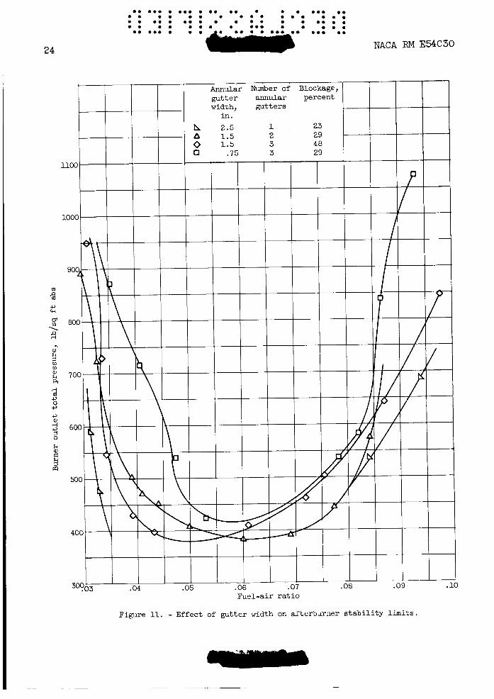
Ef fec t of Gutter Width on S t a b i l i t y L i m i t s
A comparison of the s t a b i l i t y l i m i t s obtained with the f o u r flame- holder configurations i s shown i n f i g u r e 11, where the burner o u t l e t to - t a l p r e s s u r e i s p l o t t e d against the f u e l - a i r r a t i o a t blow-out. A t a given f u e l - a i r r a t i o , combustion could not be obtained a t pressures be- low those defined by the curve f o r a p a r t i c u l a r flame holder. Both l e a n and r i c h s t a b i l i t y l i m i t s , which define the range of operable f u e l - a i r ra t ios , were determined f o r each flame holder. A t a given burner o u t l e t pressure the operable range of f u e l - a i r r a t i o s improved as the width of the annular flame-holder g u t t e r s increased from 0 . 7 5 inch t o 2 . 5 inches, an e f f e c t i n accord with t h a t found i n such other invest igat ions as r e f - erence 2 . ing pressure. decreasing pressure w a s more pronounced f o r the flame holder with
The operable range of f u e l - a i r r a t i o s narrowed with decreas- The rate of de te r fora t ion of t h e lean s t a b i l i t y l i m i t with

NACA RM E54C30 9
0.75-inch annular gutters than for the flame holders with 1.5- and 2.5- inch annular gutters. This peculiar characteristic may have been asso- ciated with the previously mentioned flickering flame observed at low pressures with the 3-ring, 29-percent blockage flame holder.
It should be noted that the stability limits for the 3-ring, 29- percent blockage flame holder probably do not represent true limits for 0.75-inch-wide gutter flame holders. The 1.5-inch interconnecting gut-
stabilized flame at some severe operating conditions where flame could not have been stabilized on the 0.75-inch gutters alone.
rJ 3 rl
ters used on the 3-ring, 29-percent blockage flame holder apparently
. Effect of Flame-Holder Blockage on Pressure Drop
On the basis of the combustion results obtained in this investiga- tion, it appears desirable to have as many annular gutters as possible to obtain high combustion efficiency and yet have wide gutters to obtain good combustion performance at low pressure. Combining the features of multiple-wide gutters into a single design, however, generally leads to high blockages and to resulting high internal losses during nonburning operation which compromise aircraft cruise performance. The effect of burner inlet velocity and flame-holder geometry on nonburning total- pressure loss is presented in figure 12 for the four flame holders in- vestigated. As the burner inlet velocity increased the nonburning total-pressure l o s s increased at an increasing rate. noted that one curve could be drawn through the data points for both 29-percent blockage flame holders even though each contained a differ- ent number of annular gutters of different widths. I n addition, at any given velocity nonburning total-pressure l o s s increased as flame-holder blockage increased. The effect of flame-holder blockage on nonburning total-pressure loss is shown more clearly in figure 13, a cross-plot of the data of figure 12. shown for burner inlet velocities of 400, 500, and 600 feet per second (burner inlet Mach numbers of 0.20, 0.25, and 0.30, respectively). It can be seen in figure 13 that at low flame-holder blockages,.low non- burning total-pressure losses are obtained. A s flame-holder blockages increase, nonburning total-pressure losses rise rapidly; therefore, in order to keep the burner total-pressure l o s s and consequent thrust loss during nonafterburner operation l o w (2 percent or less), flame-holder blockages greater than 35 percent are not advisable for burner inlet velocities greater than 500 feet per second.
Also, it is to be
Curves of pressure drop against blockage are
CONCLUDING REMARKS
An investigation was conducted in a 26-inch-diameter afterburner test rig to determine the effect of the number and width of flame-holder

............... . . e.. 0 . 0 . 0 . 0 . . 0 . . 0 . . 0 . . . . . . . . . . . . . . . . . . . . . . . . . . . . . . . . . . . . .......... .....
NACA RM E54C30 10
annular V-gutters on afterburner performance. One 1-ring, one 2-ring, and two 3-ring flame holders were investigated from a fuel-air ratio of about 0.03 to a fuel-air ratio of about 0.10. For these conditions variations in afterburner inlet total pressures from about 450 to 1300 pounds per square foot absolute were obtained.
For flame holders composed of annular V-gutters, the combustion efficiency increased as the number of annular V-gutters increased. A 3-ring, 48-percent blockage flame holder had 15 to 20 percentage points higher combustion efficiency than a 1-ring, 23-percent blockage flame holder for burner inlet total pressures from about 600 to 800 pounds per square foot absolute over a range of fuel-air ratios from 0.05 to 0.08. At burner inlet total pressures above about 700 pounds per square foot absolute, both 3-ring V-gutter flame holders (one 29-percent block- age and one 48-percent blockage) were superior to the 2-ring, V-gutter flame holder.
Gutter widths of 1.5 inches or more were found to be necessary under the conditions of operation for good low pressure performance. Below a burner inlet total pressure of about 700 pounds per square foot absolute, a 2-ring, 1.5-inch-wide V-gutter flame holder was su- perior to a 3-ring, 0.75-inch-wide V-gutter flame holder. There was local blow-out of the flame seating on the 0.75-inch V-gutters, while the flame seating on the 1.5-inch V-gutters remained bright and steady.
A large number of wide rings, however, generally lead to high blockage flame holders, which in turn result in high nonburning total- pressure losses. avoided, flame-holder blockages should not exceed about 35 percent for burner inlet velocities greater than 500 feet per second.
If pressure losses in excess of 2 percent are to be
Lewis Flight Propulsion Laboratory National Advisory Committee for Aeronautics
Cleveland, Ohio, March 30, 1954
REFERENCES
1. Nakanishi, S., Velie, W. W., and Bryant, L.: An Investigation of the Effects of Flame-Holder Gutter Shape on Afterburner Performance. NACA RM E53514, 1954.
2. Scurlock, A. C.: Flame Stabilization and Propagation in High- Velocity Gas Streams. Meteor Rep. 19, M. I. T., May 1948. (Contract NOrd 9661. )

0. 0.0 0 0 0 0 0 0 0 0 0.0 0 * o o 0 0 0 * 0 0 . 0 m o o 0 0 0 0 0 0 . 0 . 0 0 0 0 0 . 0 0 0 . 0 0 . 0 0 0 0 . 0 m o o 0 0 . 0 0 0 0 .
NACA RM E54C30 11
3. Friedman, J., Bennet, W. J., and Zwick, E. B-: The Engineering Ap- plication of Canbustion Research to Ram-Jet Engines. Fourth Sym- posium (International) on Combustion, The W i l l i a m s & Wilkins Co., 1953, pp. 756-764.
4. Rems, Paul E., and Jansen, Emmert T.: Effect of Flame-Holder Design on Altitude Performance of Louvered-Liner Afterburner. NACA RM E53Hl5, 1953.

12
............... . . 0
.. 0
.
................ .................. ................ ........................
NACA RM E54C30
4J
$ M
r: ld k
k cd
rl a3

NACA €24 E54C30 13
.. u
al I\ k
P
i% 0
3 0 d 0
I
m a, 00
8 d U
I*
h
Fl d
m 0
d
d
w
n
P
v
Q(
0
d
k

0.
0
0
0.
.
00
.
0
0
.i
o
a.
0.0
0
0
0.
NACA E
54C30

me m m m e m m e m m m bem m a m m m . m e m e a m a m e a m a m m m e e m e m m m m m e e m m e a m e m e m e m m m e e e e - em
NACA RJI E54C30
Flame holder 1 I-ring, 23 percent blockage
Flame holder 2 2-ring, 29 percent blockage
I
Flame holdar 3 %ring, 48
- J D L
15
holdar 4 percent blockage %ring, 29 percent blockage
Figure 3. - Flame-holder deta i l s .

I 16
............... ....... . . . . . . . . . . . . . . . . . . . . . . . . . . . . . . . . . . . . . . . . . 0.. . 0 . . ...... .*-. ..... NACA RM E54C30
\ 0 (b
0
Q
I (a) Station 2 .
inno I
Total-pressure probe Stream static-
Wall static-pressure
Thermocouple
pressure probe
tap
(b) Station 4.
Fi re 4. - Schematic diagram of instrumentation stations. Kiev looking downstream. )

(c) Station 5.
Figure 4. - Concluded. Schematic diagram of instrumentation stations. (View looking downstream.)
17

............... ....... . . . . . . . . . . . . . . . . . . . . . . . . . . . . . . . . . . . . . . . . . . . . . . . . . . 18
....... . .a. 0 .
NACA RM E54C30
1.0
.8
.6
.4
(a) Combustion eff ic iency.
(b) Burner i n l e t t o t a l pressure.
(c) Burner inlet veloci ty .
* .1 I r n - = # d rnh d 0 1
Lo c, O h
k k 9 1 c u m C r n *
% d-
mF4 5 e 0 .02 .04 .06 .08 .10 Fuel-air r a t i o
(d) Burner total-pressure l o s s .
Figure 5. - Perforrnanca of flame holder configuration 1. r i n g gutter; width, 2.5 inches; over-all blockage, 23 percent.
Single <-shaped

....... ............... . . . . . . . . . . . . . . . . . . . . . . . . . . . . . . . . . . ... . . . . . . . ..... ....... NACA RM E54C30 19
1.0
.%
.6
.4
(a) Combustion efficiency.
L.w
(b) Burner inlet t o t a l pressure.
(c) Burner in le t velocity.
.02 .10 Fuel-air r a t io
(d) Burner total-pressure loss.
gutters; width, 1.5 inches; over-all blockage, 29 percent. Figure 6. - Performance of flame holder configuration 2. Two V-shaped ring
............... . . 0.. 0 . . . . . . . . . . . . . . . . . . . . . . . . . . . . . . . . . . . . . . . . . . . . . . . . . . . 1 2o
1.0
.8
.6
.4
(a) Combustion efficiency.
(b) Burner i n l e t t o t a l pressure.
(e) Burner i n l e t velocity.
Fuel-air r a t i o
( a ) Burner total-pressure loss.
Figure I. - Performance of flame holder c o n f i p a t i o n 3. ring Wtters ; width, 1.5 inches; over-all blockage, 48 percent.
Three V-shaped

0 0 0.0 0 0 0 0 0 0 0 0 0 0 0 0 0 0 0 0. 0 . 0 0 . 0 0 0 0 0 0 . 0 0 0 0 0 . 0 0 0 0 0 0 0 0 0 0 0 0 . 0 0 0 0 0 0 0 0 0 0 0 0 0 . 0 0 0 0 0 0 0 0.0 0 0 0 0 0 0.0 0 0
HACA RM E54C30 21
1 .o
.8
.6
.4
(a) Combustion efficiency.
k
p7 k
(b) Burner inlet t o t a l pressure.
A i r flow, lb/sec 0 21.10 0 16.32 0 12.37 0 10.85 Solid symbols indicate blow-out
(c) Burner inlet velocity. .. l I n * *
A gJ? g 4-
5 8 5
UJ :: 5 : W I n drn 4
m a 0 .02 .04 .06 .08 .10 Fuel-air r a t i o
(d) Burner total-pressure loss.
Figure 8. - Performance of flame holder configuration 4 . Three V-shaped ring gutters; width 0.75 inch; over-all blockage, 29 percent.

22
Number of Blockage, annular percent gut ters
80
60
.. 0 . 0 . 0 . ..
NACA RM E54C30
(a) Fuel-air r a t io , 0.05.
(b) Fuel-air ra t io , 0.06.
100.
1
' A- I
I I I I I I I 600 800 1000 1200 1400
Burner i n l e t total pressure, lb/sq f t abs
(c) Fuel-air r a t io , 0.07.
Figure 9. - Effect of number of annular V-gutters on combustion eff ic iency f o r flame holders of d i f fe ren t blockages. w

0. 0.0 . . . 0. 0. . 0.. . 0.. 0 . . a . 0 . . 0 . 0 . 0 . 0 . 0 . .... a . 0 . . . 0 0 . 0 . . 0 . . ..a 0.
NACA RM E!XC30 23
(a) Fuel-air ra t io , 0.05.
(b) Fuel-air ra t io , 0.06.
Burner inlet t o t a l pressure, lb/sq f t abs
(c) Fuel-air ra t io , 0.07.
Figure 10. - Effect of number of annular V-gutters on combustion efficiency fo r flame holders of equal blockages.
24
1100 -I- 10001 I
Annular Number of Blockage, gut ter annular percent width, gut ters
1 23 2 29
3 29 3 48
Fuel-air r a t i o
Figure 11. - Effect of g d t e r width on afterburner s t a b i l i t y limits

25
.28
.24
F4d( .20
10
I
PI
d PI W
.%
m 0
r l
m .16
m 5 m E ? .12 d Q 0 9
k a,
5 p .08 rd r l 0 V
-04
0 200 400 600 800 1000 Burner i n l e t velocity, f t / sec
Figure 12 . - Effect of burner inlet ve loc i ty on nonburning total- pressure loss .

. e e.. .e e . e . e . e e . . . * e e . . e . e . . e . . e e . e 0 . e . .
.e e.. e e.. e e. * e e
e . e . e. e.. .
26 NACA RM E54C30
Flame -holder blockage, percent
Figure 13. - Effect of flame-holder blockage on nonburning total- pressure l o s s .
NACA-Langley - 0-3-54 - 350
~~
