research article open access empirical … article open access empirical assessment of a rgb-d...
TRANSCRIPT

Han et al. Visualization in Engineering 2013, 1:6http://www.viejournal.com/content/1/1/6
RESEARCH ARTICLE Open Access
Empirical assessment of a RGB-D sensor onmotion capture and action recognition forconstruction worker monitoringSangUk Han1, Madhav Achar2, SangHyun Lee3* and Feniosky Peña-Mora4
Abstract
Background: For construction management, data collection is a critical process for gathering and measuringinformation for the evaluation and control of ongoing project performances. Taking into account that constructioninvolves a significant amount of manual work, worker monitoring can play a key role in analyzing operations andimproving productivity and safety. However, time-consuming tasks involved in field observation have brought upthe issue of implementing worker observation in daily management practice.
Methods: In an effort to address the issue, this paper investigates the performances of a cost-effective and portableRGB-D sensor, based on recent research efforts extended from our previous study. The performance of an RGB-Dsensor is evaluated in terms of (1) the 3D positions of the body parts tracked by the sensor, (2) the 3D rotationangles at joints, and (3) the impact of the RGB-D sensor’s accuracy on motion analysis. For the assessment,experimental studies were undertaken to collect motion capture datasets using an RGB-D sensor and a marker-based motion capture system, VICON, and to analyze errors as compared with the VICON used as the ground truth.As a test case, 25 trials of ascending and descending during ladder climbing were recorded simultaneously withboth systems, and the resulting motion capture datasets (i.e., 3D skeleton models) were temporally and spatiallysynchronized for their comparison.
Results: Through the comparative assessment, we found a discrepancy of 10.7 cm in the tracked locations of bodyparts, and a difference of 16.2 degrees in rotation angles. However, motion detection results show that theinaccuracy of an RGB-D sensor does not have a considerable effect on action recognition in the experiment.
Conclusions: This paper thus provides insight into the accuracy of an RGB-D sensor on motion capture in variousmeasures and directions of further research for the improvement of accuracy.
Keywords: Motion capture; Action recognition; Motion classification; RGB-D sensor; Machine learning
IntroductionDuring a construction project, data collection is criticalto the evaluation and control of ongoing project perfor-mances. The complexity of construction environmentsand the dynamics of moving equipment and humanresources, however, often pose a challenge in undertak-ing such tasks on a jobsite. Particularly, the time-consuming tasks required for worker monitoring cangive rise to the issue of implementing field observation
* Correspondence: [email protected] of Civil & Environmental Engineering, University of Michigan,Ann Arbor, MI 48109, USAFull list of author information is available at the end of the article
© 2013 Han et al.; licensee Springer. This is anAttribution License (http://creativecommons.orin any medium, provided the original work is p
in a daily management practice (Johnson and Sackett1998). For efficient field data acquisition, research ef-forts have thus been made to investigate and proposeavailable sensing devices—such as cameras, laser scan-ners, and the combination of sensors (e.g., ultra wide-band and physiological status monitoring devices)—forthe tracking of human movements and the analysis ofconstruction activities (Cheng et al. 2013; Gong andCaldas 2011; Peddi et al. 2009; Gonsalves and Teizer2009). The previous studies provide valuable insightinto the analysis of human postures and actions, butfurther research is still needed for the capture of an ar-ticulated motion and the modeling of its kinematics.
Open Access article distributed under the terms of the Creative Commonsg/licenses/by/2.0), which permits unrestricted use, distribution, and reproductionroperly cited.

Han et al. Visualization in Engineering 2013, 1:6 Page 2 of 13http://www.viejournal.com/content/1/1/6
Along this line, an RGB-D sensor—such as the MicrosoftKinect sensor—has gained great attention as a cost-effective and readily available device for motion capture.Since it was released in 2010, the Kinect has been ac-
tively studied as a motion capture device to record themovement of human subjects. In this regard, action rec-ognition techniques—in particular—have been exploredfor the detection of specific actions using the motioncapture data for use with operation and safety analysis inconstruction. For example, Weerasinghe et al. (2012)propose a Kinect-based tracking framework for thelocalization of workers and the analysis of their move-ment patterns, which could potentially be used for pro-ductivity measurement. For operation analysis, Escorciaet al. (2012) also present an action recognition techniqueto classify construction workers’ actions based on thecolor and depth information from a Kinect. On theother hand, Ray and Teizer (2012) utilize a Kinect forthe pose analysis of construction workers to classifyawkward postures based on ergonomic rules duringsafety and health training, and Han et al. (2013) studythe unsafe action detection of workers for safety beha-vior monitoring with motion capture data from a Kinect.These studies have thus demonstrated the great poten-tial of the Kinect to gather motion information from ajobsite, as well as the great potential of its applicationsto construction management. To validate the proposedapproach, however, the prior work has mainly focusedon the performances of motion classification and detec-tion rather than the accuracy of estimated postures andactions (e.g., 3D human skeleton models). The results inthe studies suggest that pose estimation is computation-ally verified to a certain extent, but the accuracy of theKinect solely when used for motion capture still remainsunexplored. Taking into account that one of the mainuses of the Kinect is to estimate 3D body skeletons ofhumans and track their movements over time, the thor-ough assessment of a Kinect-based motion capture sys-tem will thus help elucidate: (1) up to what degree ofaccuracy a Kinect sensor can detect and track the 3Dpositions of body parts; (2) to what research areas theKinect can potentially be applied, depending on the ac-curacy; and (3) which processes of motion analysis causecomputational errors for the debugging of action recog-nition systems.This paper evaluates the performance of the Kinect
sensor on motion capture and action recognition forconstruction worker monitoring. An experimental studyis undertaken to compare the accuracy of a Kinect witha commercial marker-based motion capture system,VICON, which has been used as the ground truth in priorwork (Dutta 2012; Stone and Skubic 2011; Fernández-Baena et al. 2012). A VICON tracks the 3D locations of re-flective markers attached to body parts with multiple
cameras (e.g., 6 or 8 cameras), thereby minimizing occlu-sions and producing accurate tracking results. Extendedfrom our previous work (Han et al. 2012), this paper per-forms the error analysis based on: (1) the estimated 3Dpositions of body joints, (2) the recomputed 3D rotationangles at particular joints, and (3) the effect of the motioncapture accuracy on motion detection. The rest of thispaper is organized as follows. Background section providesa background on the Kinect sensor and its performanceevaluation. Methods section demonstrates a researchmethodology used to compute and analyze the three typesof errors for the comparative study. Experiment sectiondescribes the experimental process for the collection ofmotion capture datasets with both a Kinect and a VICON.Results, including the error analysis, are presented anddiscussed in Results and discussion section. Finally, Con-clusion section summarizes the findings of this study andsuggests the direction of future research.
BackgroundThis section summarizes the pros and cons of an RGB-D sensor (i.e., Kinect) for motion capture, and reviewsprevious work on the performance evaluation of aKinect motion capture system. Based on the literaturereview, further research efforts required in this domainare identified.
An RGB-D sensor for motion tracking and analysisThe Kinect sensor was initially developed as a motion-sensing device for video gaming. A Kinect consists oftwo main components—one is a RGB camera that pro-duces images at a 640 × 480 resolution, while the otheris a depth sensor that measures the depth information ofthe image (Rafibakhsh et al. 2012). In addition, the depthsensor is comprised of both a projector and an infrared(IR) camera, all of which projects a structured IR lightonto the scene and measures the depth by analyzing thedistortion of the IR light (Weerasinghe et al. 2012;Khoshelhan 2011). Accordingly, the Kinect allows notonly for the 3D reconstruction of a scene with pointclouds but also for the 3D skeleton extraction of a hu-man subject as combined with the motion capture solu-tions (e.g., OpenNI, Microsoft Kinect for Windows SDK,iPi Soft Motion Capture). In terms of the image process-ing for motion capture, the measured depth can be usedfor the building of 3D human models through 2D poseestimation (i.e., 2D skeletons with depth), as well as forthe direct inference of 3D poses by integrating the depthinto the pose estimation process. On the other hand, theuse of IR light brings about constraints in the practicalapplication of a Kinect to a field setting. For example,the Kinect’s sensitivity of IR light to sunlight may causeunreliable motion capture outcomes in an outdoorenvironment, and its operating ranges for motion
Han et al. Visualization in Engineering 2013, 1:6 Page 3 of 13http://www.viejournal.com/content/1/1/6
capture are also known to be limited (e.g., 0.8–4 m)(Weerasinghe et al. 2012; Han et al. 2013). Nevertheless,previous studies report that the operating distance forobject tracking can be extended up to 10 m (Rafibakhshet al. 2012) and 7.5 m (Ray and Teizer 2012) from acamera; hence, further investigation is required to clarifythe range issue. Though limited to indoor applications,the Kinect still has the following notable advantages formotion sensing: (1) it requires no additional body at-tachment (e.g., markers, a special suit), which allows forworker observation without the interference of ongoingwork; (2) the cost of a sensor (e.g., approximately 150–250 USD) is quite competitive, compared with othermotion capture systems (e.g., approximately 96–120KUSD for a marker-based VICON system) (Han et al.2013); (3) the minimum number of sensors for motiontracking is only one Kinect; and (4) it provides an easy-
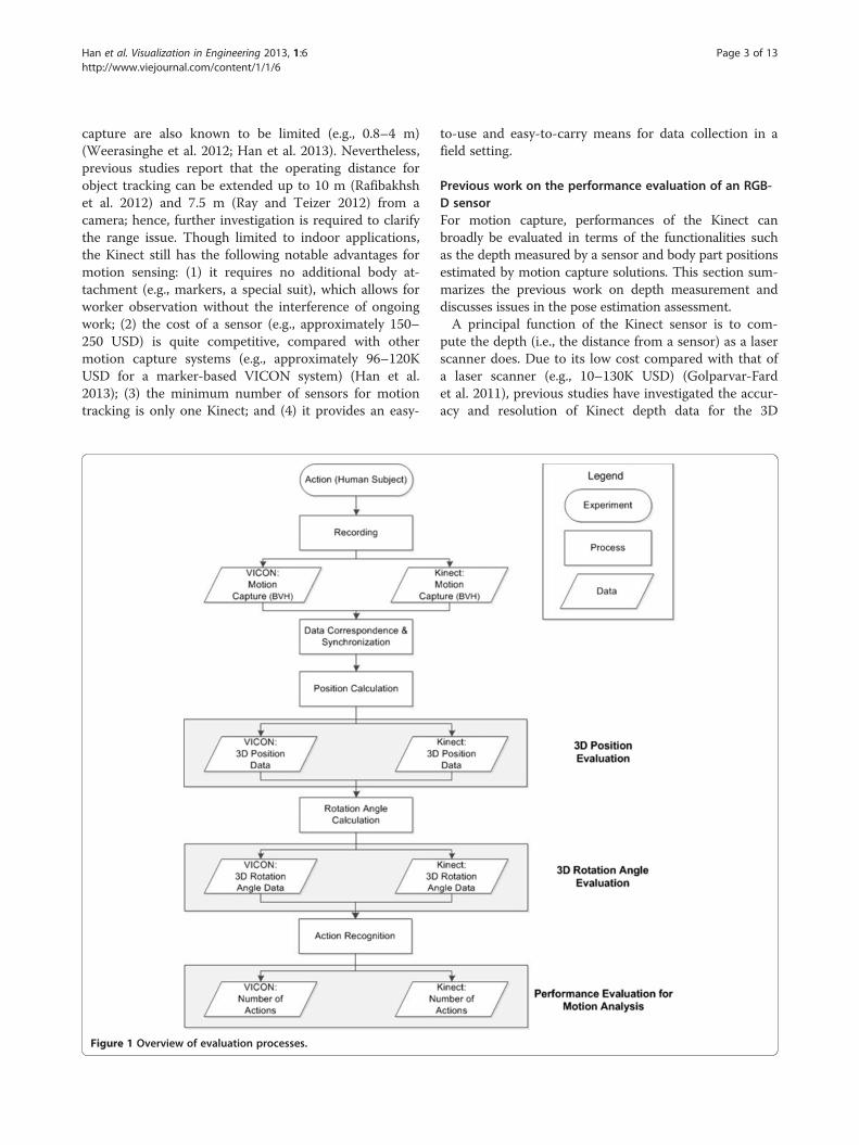
Figure 1 Overview of evaluation processes.
to-use and easy-to-carry means for data collection in afield setting.
Previous work on the performance evaluation of an RGB-D sensorFor motion capture, performances of the Kinect canbroadly be evaluated in terms of the functionalities suchas the depth measured by a sensor and body part positionsestimated by motion capture solutions. This section sum-marizes the previous work on depth measurement anddiscusses issues in the pose estimation assessment.A principal function of the Kinect sensor is to com-
pute the depth (i.e., the distance from a sensor) as a laserscanner does. Due to its low cost compared with that ofa laser scanner (e.g., 10–130K USD) (Golparvar-Fardet al. 2011), previous studies have investigated the accur-acy and resolution of Kinect depth data for the 3D

Figure 2 Y-axis rotation for data correspondences; (a) a local coordinate system of motion capture data, (b) a global coordinatesystem, and (c) Y-axis rotation between (a) and (b).
Han et al. Visualization in Engineering 2013, 1:6 Page 4 of 13http://www.viejournal.com/content/1/1/6
modeling of indoor environments, as well as for motionsensing. Khoshelham and Elberink (2012) report that thedepth discrepancies between pairs of point clouds gener-ated by a Kinect and a high-end laser scanner (i.e., FaroLS 880) are less than 3 cm for 84% of the point pairs,and that the point spacing in the depth direction (i.e.,resolution) is about 2 mm, 2.5 cm, and 7 cm at the 1-,3-, and 5-m distance. Rafibakhsh et al. (2012) also com-pare the accuracy and resolution of a Kinect with a laserscanner (i.e.. a Faro Focus3D scanner) and reveal thatthe average distance error between the point pairs is3.49 cm, and that the resolution of the Kinect is about 4times less than that of a laser scanner at 1.7- to 3.4-mdistances from a sensor. Dutta (2012) measures the dif-ferences in distances between a Kinect and a VICON fora 0.1-m cube over a range of 1–3 m from a sensor, andthe Root-Mean-Square Errors (RMSEs) are 6.5 mm in ahorizontal direction, 5.7 mm in a vertical direction, and10.9 mm in depth. On the other hand, Stoyanov et al.(2011) evaluate the accuracy of a Kinect in comparisonwith a laser scanner using the Three-Dimensional Nor-mal Distributions Transform (3DNDT), which is a
Figure 3 Experimental settings; (a) configurations of Kinect and VICOsubject wearing a black suit and attaching reflective markers.
spatial representation accuracy evaluation technique,and conclude that the Kinect sensor performs wellwithin 3.5-m distances. In Chow et al. (2012), a 3D re-construction model of a mannequin is computed andcompared with a laser scanner, and an RMSE of11 mm is observed. In sum, previous studies reviewedherein conclude that the depth measurement and reso-lution of the Kinect are promising within a short range(e.g., 3 m), though not as accurate as those of a laserscanner, particularly in longer ranges.The accuracy of motion capture data obtained with the
Kinect has also been investigated. In Livingston et al.(2012), human skeletons tracked by a Microsoft softwaredevelopment kit are evaluated based on the positions ofbody joints (e.g., arms and hands) along a meter stick, andthe average error and standard deviation in this experimentare 5.6 mm and 8.1 mm, respectively. Fernandez-Baenaet al. (2012) conduct an experiment associated with re-habilitation treatments to compare the accuracy between aKinect—combined with Natural Interaction Technology forEnd-user (NITE)—and a VICON in terms of the rotationangles of knee, hip, and shoulder joints, defined as angles
N sensors, (b) a VICON sensor, (c) a Kinect, and (d) a human

Figure 4 Human skeleton models; (a) a Kinect, (b) a VICON, and (c) a converted skeleton model (number: body joint ID).
Han et al. Visualization in Engineering 2013, 1:6 Page 5 of 13http://www.viejournal.com/content/1/1/6
between two vectors of body parts (e.g., one from knee tofoot); the results show that the differences in rotation anglesrange from 6.78 to 8.98 degrees for a knee, from 5.53 to9.92 degrees for a hip, and from 7 to 13 degrees for a shoul-der. In the study of physical rehabilitation by Chang et al.(2012), the trajectories of the right hand, right elbow, andright shoulder that are tracked by a Kinect with OpenNI/NITE middleware are visually compared with those ofmarker-based OptiTrack motion capture system; the trajec-tories of a hand and an elbow are matched between twosystems, while a shoulder is not accurately tracked by aKinect system. To apply the Kinect to construction, how-ever, further research efforts are required to address the fol-lowing issues on the assessment of its motion captureperformances: (1) the motions involved in constructionactivities need to be investigated, (2) the tracking resultsof full body joints need to be evaluated due to the cha-racteristics of construction activities (i.e., manual work),and (3) the impact of the Kinect system’s performanceson action recognition needs to be studied for the analysisof construction worker monitoring and operation.
MethodsThe objective of this paper is to assess the accuracy ofKinect motion capture data for the motion analysis ofconstruction operations; Figure 1 illustrates an overviewof evaluation processes comparing the outputs ofVICON and Kinect motion capture systems. The evalua-tions are based on the error analysis of tracked 3D posi-tions of full body joints, the 3D rotation angles at bodyjoints used as a feature for motion classification, and theeffect of the accuracy on action recognition. To compute
Table 1 Description of body parts and their joint IDs in Figur
Body part ID 1 2 3
Body part Left upper leg Left leg Left foot
Body part ID 8 9 10
Body part Left forearm Left hand Right arm
the tracking errors, a VICON is used as the ground truthfor motion tracking, and the iPi Motion Capture solu-tion (http://ipisoft.com) is used with Kinect sensors totrack the 3D positions of a human subject and extract3D skeletons; the iPi Motion capture system estimateshuman poses mainly based on the depth measurementsof a human body, and is thus less affected by a per-former’s appearance (e.g., special black suit and markersrequired by a VICON). In the experiment, human mo-tions are thus simultaneously recorded with a Kinectand a VICON, and corresponding body joints of bothsystems—synchronized in time and space domains—arecompared to compute the errors of Kinect outcomes. Inaddition, the ethics of this study including human sub-jects has been approved by the University of MichiganInstitutional Review Board and the reference number isHUM00061888.
Data correspondence and synchronizationTo compare the pose estimation results of a Kinect anda VICON, coordinate systems and data frames of bothsystems are matched through the rotation of coordinatesystems and the synchronization of frames. For thespatial correspondence, local coordinate systems of both(i.e., coordinate systems defined by each system—anx-axis defined by the pelvis and a y-axis defined by thespine) are rotated about the y-axis into a global coordin-ate system (i.e., an absolute coordinate system newly de-fined for the coordinate system matching—a subjectalways faces the front) (Figure 2). In this experiment, alocal coordinate system is defined based on the positionsof a hip (i.e., Phip), a spine (i.e., Pspine), and a pelvis (i.e.,
e 4c
4 5 6 7
Right upper leg Right leg Right foot Left arm
11 12 13 14
Right forearm Right hand Neck Head

Figure 5 3D position trajectories of a Kinect and a VICON in x-, y-, and z-directions over the first 500 frames; (a) left upper leg, (b) leftleg, (c) left foot, (d) right upper leg, (e) right leg, (f) right foot, (g) left arm, (h) left forearm, and (i) left hand.
Han et al. Visualization in Engineering 2013, 1:6 Page 6 of 13http://www.viejournal.com/content/1/1/6

Han et al. Visualization in Engineering 2013, 1:6 Page 7 of 13http://www.viejournal.com/content/1/1/6
Ppelvis) tracked by motion capture systems. The y-axisrotation angle, Ry, is calculated using Eq. (1):
Ry ¼ cos−1 →zp;x� Zx→ þ→zp;y� Zy
→ þ→zp;z� Zz→� �
ð1Þ
where →zp;x ;→zp;y ; and →zp;z denote x, y, and z components
of zp→
in Figure 2c, and Zx→;Zy→; and Zz
→denote x, y, and z
components of Z→
in Figure 2b. Then, entire datasets ofboth systems are rotated using a rotation matrix obtainedfrom Ry. In this manner, skeleton models of both systemsface the front (i.e., z-axis), thus allowing for the compari-son of skeletons in the same coordinate system regardlessof viewpoints.In the experiment, the synchronization of a pair of
datasets is manually performed by identifying the sameframe. For instance, we observe the frame in which aperformer contacts a ladder’s rung with a foot, and thenwe search for the exact frame among adjacent frames(e.g., 2 frames before and after the frame) by selectingthe moment minimizing the distance between twodatasets. In addition, the frame rates of the two systemsare different (e.g., 120 frames per second for a VICON,and 30 frames per second for a Kinect). In the case of aVICON, thus 1 frame for every 4 is selected for the per-formance comparison. The accuracy is evaluated usingRMSE in Eq. (2):
RMSE ¼ffiffiffiffiffiffiffiffiffiffiffiffiffiffiffiffiffiffiffiffiffiffiffiffiffiffiffiffiffiffiffiffi∑n
i¼1
xv;i−xk;i� �2
n
sð2Þ
where xv denotes a VICON data value, xk denotes aKinect data value at each frame (i), and n is the totalnumber of frames.
Action recognitionTo evaluate the impact of motion tracking accuracy onaction recognition, this paper adopts the action detec-tion framework presented in our previous work (Hanet al. 2013). The framework consists of the dimensionreduction of high-dimensional motion data, similarity
Table 2 3D position comparison (cm) of body joints between
ID 1 2 3 4 5 6 7
3D 2.7 8.3 8.8 3.1 10.0 9.5 6.8
(Std.) (0.4) (3.2) (3.0) (0.7) (3.7) (3.6) (2.3) (
X 2.3 5.2 4.5 2.3 5.9 2.9 4.5
(Std.) (0.2) (3.9) (3.0) (0.2) (3.7) (2.7) (3.2) (
Y 1.3 4.4 4.5 1.8 6.0 5.8 3.6
(Std.) (1.3) (3.0) (3.7) (1.3) (3.1) (4.1) (1.5) (
Z 0.6 4.8 6.0 0.9 5.4 7.0 3.7
(Std.) (0.6) (4.2) (3.6) (0.6) (4.5) (3.4) (3.6) (
(Unit: cm).
measurements between a pair of motion data, and mo-tion classification based on the measured similarity.First, dimension reduction is needed due to the high di-mensions in motion data (e.g., 78), which hinder efficientand accurate action detection. Thus, we use Kernel Prin-cipal Component Analysis (Kernel PCA) (Schölkopfet al. 1998) to map motion data onto a 3D space, andthen we compare the trajectories of datasets in the low-dimensional coordinate. In this space, a trajectory repre-sents a sequential movement of postures (i.e., actions),and actions can be recognized by comparing the tem-poral patterns of transformed datasets. For the patternrecognition, temporal-spatial similarity between a pair ofdatasets is quantitatively measured using Dynamic TimeWarping (DTW) (Okada and Hasegawa 2008). In thisstudy, DTW measures Euclidean distances betweendatasets by warping the datasets in a time domain so asto compare datasets, even the sizes (i.e., durations) ofwhich are different. For the performance evaluation, thusthe similarity between a motion template (i.e., one trialof action datasets) and the entirety of the data is com-puted over all of the frames, and the behavior (e.g.,fluctuation) of measured similarities is compared to in-vestigate the effect of motion capture systems on thedetection accuracy. Eventually, we perform the actiondetection that recognizes actions based on similaritiesby observing the ones with less similarity than athreshold (i.e., a classifier learned through classifica-tion); the detection results of Kinect and VICONdatasets are compared in terms of accuracy (i.e., thefraction of correctly classified actions among all sam-ple actions), precision (i.e., the fraction of correctlydetected actions among detected ones), and recall (i.e.,the fraction of correctly detected actions among onesthat should be detected).
ExperimentTo collect motion capture data, a lab experiment wasconducted in the University of Michigan 3D Lab (Hanet al. 2012); experimental configuration and scenes areillustrated in Figure 3. In this experiment, actions during
a Kinect and a VICON
8 9 10 11 12 13 14 Mean
9.1 24.3 6.8 12.4 21.7 19.0 7.7 10.7
3.5) (12.0) (2.7) (4.9) (12.2) (1.2) (2.3) (5.3)
4.4 11.3 4.1 8.7 14.7 4.1 4.8 5.7
4.0) (10.6) (3.3) (5.1) (10.9) (3.2) (3.9) (5.1)
3.5 17.4 3.1 4.6 10.9 17.3 4.7 6.4
3.1) (13.7) (1.5) (2.5) (10.4) (1.0) (1.0) (5.1)
7.1 12.6 4.4 7.6 11.7 6.6 3.8 5.9
6.3) (9.0) (3.7) (6.1) (11.6) (3.6) (3.0) (5.4)

Figure 6 Comparisons of 3D position estimation between a Kinect and a VICON for a trial of ladder climbing; frames (a) 310, (b) 335,(c) 360, (d) 385, (e) 410, and (f) 435. 3D position trajectories of a Kinect and a VICON in the x-, y-, and z-directions over the first 500 frames;(j) right arm, (k) right forearm, (l) right hand, (m) neck, and (n) head (Note: graphs are scaled for each body part).
Han et al. Visualization in Engineering 2013, 1:6 Page 8 of 13http://www.viejournal.com/content/1/1/6

Figure 7 Eigen-decomposition for the internaldimensionality estimation.
Han et al. Visualization in Engineering 2013, 1:6 Page 9 of 13http://www.viejournal.com/content/1/1/6
ladder climbing were recorded and analyzed; in con-struction, 16% of fatalities and 24.2% of injuries werecaused by falls from a ladder in 2005 (CPWR 2008). 25trials of each action (i.e., ascending and descending)taken by 1 subject were recorded with six 4-mega-pixelVICON sensors and a Kinect sensor. In total, 3,136 and12,544 frames were collected with the Kinect and theVICON, respectively; and the datasets were synchro-nized for each system to have 3,136 frames for thecomparison.In this experiment, human skeleton models of the
VICON and Kinect systems were slightly differentin terms of the hierarchical structures of a humanbody; graphical illustrations of skeleton modelsextracted from each system are presented in Figure 4.Thus, for the comparison, corresponding body jointsbetween the two systems are selected to convert thetwo models into the same form of a skeletal model(Figure 4c), and positions of such joints, as well astheir rotation angles, are computed from motioncapture data. For instance, motion capture data usedin this study was in the Biovision Hierarchy (BVH)format (Meredith and Maddock 2001), in which ahuman posture at each frame is represented onlywith 3D Euler rotation angles. The BVH format alsodefines the 3D positions of body joints (i.e., transla-tions) in an initial pose (e.g., T-pose as shown inFigure 4). This rotation and translation informationforms a transformation matrix allowing for the com-putation of the 3D positions of all body joints in aglobal coordinate system (Meredith and Maddock2001). To re-calculate Euler rotation angles (e.g., ro-tations in an order of x-, y-, and z-axes in thisstudy) with respect to the converted skeleton model,an axis-angle between two body parts is first com-puted, a quaternion is defined with the axis-angleand axis vector, this quaternion forms a rotationmatrix, and lastly a rotation angle is computed basedon the rotation matrix (Han et al. 2012). Conse-quently, the 3D positions and rotation angles of eachbody part (Figure 4c) are compared to evaluate thetracking performances of the two systems; Table 1describes body joint IDs corresponding to body partsin Figure 4c.
Results and discussionTo assess the performance of the Kinect as a motioncapture system, we compare it with the VICON in termsof the results of: (1) 3D positions of body joints, (2) 3Drotation angles, and (3) motion detection for the datasetssimultaneously collected through a lab experiment.Based on the error analysis, the applicability of theKinect to the motion analysis of construction workers isdiscussed.
3D Position evaluationTo compare the 3D positions of body joints tracked byboth systems, postures at each frame were iterativelyrotated about the y-axis in a global coordinate system(Figure 2) over all of the temporally synchronized frames.Figure 5 visualizes skeleton models extracted from bothsystems at selected frames in the coordinate where twodatasets are mapped. In this manner, the inspection of en-tire frames (i.e., animations) visually confirmed that thedata correspondence and synchronization were success-fully carried out for the two datasets. Through the visualinvestigation, we found that overall a Kinect model wasclosely matched with aVICON model, while hands and feetin particular were not exactly located in the same place.For the quantitative assessment, RMSEs of body parts
are computed over the entire frame using Eq. (2).Table 2 summarizes the RMSEs and standard deviationson distance differences in x-, y-, and z-directions, aswell as in a 3D space; body part IDs refer to Figure 4and Table 1. The temporal trajectories of the 3D posi-tions of both systems in the first 500 frames are alsopresented in Figure 6. Compared with a VICON, aKinect produces the discrepancy of 10.7 cm in a 3D co-ordinate, and no significant disparity in each directionwas identified. The results show that the largest RMSEsare caused by the tracking of both hands (i.e., IDs 9 and12) among body parts, and the large standard deviationsof hands also indicate that the locations of such bodyparts are inconsistently estimated over the frames. Yet,Figures 6i and 6l imply that the patterns of a Kinect atlarge are still similar with those of a VICON. Inaddition, a large RMSE—the third greatest after that ofthe two hands—is found in a neck (i.e., ID 13). However,the standard deviation is relatively small, and most

Table 3 Rotation angle comparison (degree) at bodyjoints between a Kinect and a VICON
ID 1 2 4 5 7 8 10 11 13 Mean
3D 5.1 5.6 6.2 8.2 13.9 34.2 18.9 49.0 4.4 16.2
(Std.) (5.2) (5.1) (4.9) (6.2) (7.8) (29.6) (15.4) (40.0) (3.8) (18.0)
X 6.6 7.3 6.7 8.1 12.1 31.2 18.7 38.6 6.0 15.1
(Std.) (6.2) (7.3) (6.1) (8.1) (6.3) (27.7) (15.6) (34.5) (2.0) (16.5)
Y 3.3 3.5 3.9 7.2 6.3 21.9 5.2 48.3 0.2 11.1
(Std.) (3.2) (2.9) (2.7) (5.1) (5.5) (19.6) (5.2) (33.8) (0.2) (13.5)
Z 5.6 5.9 7.9 9.2 23.4 49.5 32.9 60.0 7.0 22.4
(Std.) (5.6) (4.1) (5.1) (5.1) (10.6) (38.4) (21.0) (49.7) (6.3) (22.7)
(Unit: degree).
Han et al. Visualization in Engineering 2013, 1:6 Page 10 of 13http://www.viejournal.com/content/1/1/6
errors result from differences in a y-direction; this sug-gests that the tracking positions of a neck by the two sys-tems are slightly different, as shown in Figure 6m. Next,relatively large RMSEs are caused by forearms (i.e., IDs 8and 11), legs (i.e., IDs 2 and 5), and feet (i.e., IDs 3 and 6).As observed with hands, the trajectories of those bodyparts also similarly fluctuate over time with both a Kinectand a VICON (Figures 6h, 6k, 6b, 6e, 6c, and 6f).The results show that the discrepancy between the
Kinect motion capture system and a marker-based sys-tem is 10.7 cm on average in 3D positions. However, theestimated trajectories reveal that the Kinect sensor canstill capture patterns of movements well, even with onlyone sensor. On the other hand, the use of one sensormay introduce the issue of occlusions. In the experi-ment, a Kinect sensor was positioned at the rear of aperformer (Figure 3), and hence the performer’s handswere frequently occluded by the performer, himself/her-self. Also, forearms and legs, which were sometimes oc-cluded as a performer climbed up and down a ladder,caused larger errors than other body parts. This implies
Figure 8 Dimension reduction results of (a) a VICON and (b) a Kinect
that occlusions may have been a major source of errorsin this experiment.
3D Rotation angle evaluationIn this experiment, rotation angles were the outcomes ofboth motion capture systems. However, other types (e.g.,joint angles) of motion data—which can efficientlycharacterize human postures—can be obtained frommotion capture systems and used as a feature for motionanalysis. Taking into account that the selection of dis-criminating features significantly affects the classificationperformances (Mangai et al. 2010), we compared threedata types in our previous study: rotation angles, jointangles (i.e., horizontal and vertical joint angles between abody part and x-y and x-z planes in a global coordinatesystem), and position vectors (i.e., normalized vectors ofbody parts) (Han, Lee, and Peña-Mora: Comparativestudy of motion features for similarity-based modelingand classification of unsafe actions in construction, sub-mitted). The result reveals that, in the experiment, rota-tion angles outperformed the other two data types inapplying the motion detection framework, which is alsoadopted in this paper. In this respect, 3D rotation anglesused as inputs for motion analysis are compared toevaluate the accuracy of the Kinect and its impact on ac-tion recognition.For the assessment, rotation angles were computed
according to the converted skeleton model in Figure 4c.A rotation angle at a particular joint is defined as theangle rotating a vector of the joint (i.e., a vector fromthe joint to its child joint) from a corresponding vectorin an initial pose. Thus, end-joints such as body part IDs3, 6, 9, 12, and 14 are excluded from the comparison asnot defined. Thus at the available joints, RMSEs ofrotation angles in the x-, y-, and z-directions, as well asmean RMSEs of the three directions, were computed
(axis: eigen-vector; and unit: eigen-value).

Figure 9 Comparison of similarity measurements between a VICON and a Kinect; (a) ascending, and (b) descending actions.
Han et al. Visualization in Engineering 2013, 1:6 Page 11 of 13http://www.viejournal.com/content/1/1/6
through all of the frames, and the results are presentedin Table 3 (extended from Han et al. 2012). Comparedto a VICON, overall the mean difference of 16.2 degreesand the standard deviation of 18.0 degrees were ob-served for the average of the three directions. For eachdirection, large errors occur in an order of z-, x-, and y-axis rotations (the z-axis has the largest error). In par-ticular, the largest errors of up to 49 degrees werecaused by forearms (i.e., IDs 8 and 11), which define thehand position. This implies that position errors at fore-arms and hands, which determine the rotation angles atforearms, can heavily magnify errors of rotation anglesas combined. This phenomenon also explains the largeerrors of arms (i.e., IDs 7 and 10). The position errors ofarms and forearms were not relatively large, but thecombination of errors produces the second largest errorsof rotation angles at the arms. Except for forearms andarms, the rotation angle errors of other body parts wereless than 10 degrees.
Performance evaluation for motion analysisTo evaluate the performance of the Kinect for motionanalysis, we applied a motion detection method (Hanet al. 2013) to motion capture datasets from a Kinectand a VICON, and compared the results of detectionbased on conventional measures of classification perfor-mances (i.e., accuracy, precision, and recall). For motionanalysis, dimensionalities of motion datasets were firstreduced using kernel PCA. To determine the dimensionto be reduced, eigen-decomposition was performed forthe estimation of internal dimensionality in the datasets.
Table 4 Detection error comparison
Datasource
Actiontype
# ofactionsin data
# of correctly detected actions
Template (TP) Other action (TN)
Vicon Ascending 25 25 25
Descending 25 25 25
Kinect Ascending 25 24 25
Descending 25 25 25
As shown in Figure 7, the first three eigen-vectors havelarge eigen-values, which means that most informationcan be represented with three dimensions. In this regard,motion datasets were transformed onto a 3-dimensionalcoordinate; Figure 8 illustrates the distributions of eachdataset in the low-dimensional space. In this space, adata point represents posture information at one frame,and hence the trajectories describe actions as changingpostures over time. In Figure 8, the minimum and max-imum values of each system are slightly different; for ex-ample, the ranges of x, y, and z values of Vicon are[−8.5*1015, 1.1*1015], [−1.0*1015, 1.6*1015], and [−6.0*1014,4.3*1014], while the ranges of x, y, and z values of Kinectare [−4.9*1015, 0.9*1015], [−0.4*1015, 1.5*1015], and[−3.5*1014, 3.2*1014], respectively. However, the results in-dicate that the motion data captured by both systemscould be mapped onto the same space. More importantly,despite large errors associated with body parts (e.g., armsand forearms) in rotation angles, the result of mapping(i.e., the transformation of high-dimensional data onto alow-dimensional space) reveals that the patterns of motiondata can be preserved though dimension reduction; actiondetection is based on the comparison of patterns (i.e., tra-jectories) in a 3D space.To compare the trajectories between actions, temporal-
spatial similarities are measured using the DTW. In thisexperiment, one trial of datasets among 25 for each as-cending and descending action was used as a motiontemplate to compare its similarity with testing data anddetect similar actions when the similarity is higher—orthe distance is smaller—than a threshold. To avoid a
# of incorrectly detected actions Acc.(%)
Prec.(%)
Rec.(%)Not detected (FN) Mis-detected (FP)
0 0 100 100 100
0 0 100 100 100
1 0 98 100 96
0 0 100 100 100

Han et al. Visualization in Engineering 2013, 1:6 Page 12 of 13http://www.viejournal.com/content/1/1/6
biased assessment, a motion template from a Kinectand a VICON were compared with the same testingdataset (i.e., an entire frame of VICON data) for the de-tection; for instance, consistent errors (e.g., constantlyestimating locations of a hand at a wrong but similarplace) caused by a Kinect over the frames can positivelyaffect the detection accuracy. The similarities measuredover all of the frames are illustrated in Figure 9. Not-withstanding errors in Kinect data, the fluctuations ofboth datasets behave similarly over time. This resultsuggests that the errors of a Kinect system have not sig-nificantly affected the motion analysis in this experi-ment. Detection results (Table 4) also show that theaccuracy, precision, and recall of a Kinect system are98%, 100%, and 96%, respectively; only one trial among25 was not detected.
ConclusionsThis paper evaluates the performance of an RGB-D sen-sor (e.g., Kinect sensor) as a motion capture systembased on the accuracy in estimated 3D positions andcomputed rotation angles, and the sensor’s impact onaction recognition. We conducted an experiment to col-lect motion capture data for 25 trials of ladder climbingactions, and we analyzed the accuracy on the datasets toidentify the sources of errors. In the experiment, a 3Dposition RMSE and standard deviation were 10.7 cmand 5.3 cm, compared with a VICON. In the case of ro-tation angles, the RMSE and standard deviation were16.2 degrees and 18.0 degrees, respectively. The rotationangles were used for motion detection, and the resultsshow that among 25 trials, only 1 case of an ascendingaction was incorrectly detected (i.e., accuracies of 98%and 100% for ascending and descending actions, respect-ively). The experimental study implies that the inaccur-acy of the Kinect motion capture system, particularly onoccluded body parts, did not have a considerable effecton action recognition. However, the Kinect system pro-duces large errors in estimating the positions of bodyparts, which can even increase errors as converted intorotation angles. The relatively lower accuracy of theKinect system than that of marker-based systems canthus limit its application to construction; for example,the Kinect system may not be suitable for applicationsrequiring high accuracy such as hand-related ergonomicanalysis. Moreover, further investigation of Kinect per-formance evaluation on various actions (e.g., walking,running, lifting and carrying an object, and slipping) inconstruction operations is required for the thorough re-view of the feasibility of a Kinect for construction appli-cations (e.g., productivity and safety). In addition,occlusions by a performer or other moving objects mightbe common in construction; thus a single Kinect motioncapture system may potentially produce noise in a field
setting. In this respect, further investigation on the useof multiple Kinect sensors is required to collect reliablemotion information on a jobsite.
Competing interestsThe authors declare that they have no competing interests.
Authors’ contributionSH carried out the motion analysis studies, participated the sequencealignment and drafted the manuscript. MA undertook the experiments tocollect data using a motion capture system. SL and FP directed the entireprocesses of this study, provided suggestions on each procedure in the datacollection and analysis, and reviewed the manuscript. All authors read andapproved the final manuscript.
Author details1Department of Civil and Environmental Engineering, University of Illinois atUrbana-Champaign, Urbana, IL 61801, USA. 2Department of ComputerScience, University of Michigan, Ann Arbor, MI 48109, USA. 3Department ofCivil & Environmental Engineering, University of Michigan, Ann Arbor, MI48109, USA. 4Department of Civil Engineering and Engineering Mechanics,Earth and Environmental Engineering, and Computer Science, ColumbiaUniversity, New York, NY 10027, USA.
Received: 18 March 2013 Accepted: 6 May 2013Published: 9 July 2013
ReferencesChang, CY, Lange, B, Zhang, M, Koenig, S, Requejo, P, Somboon, N, Sawchuk,
AA, & Rizzo, AA. (2012). Towards pervasive physical rehabilitation usingMicrosoft Kinect (pp. 159–162). San Diego, CA: 2012 6th internationalconference on pervasive computing technologies for healthcare(pervasiveHealth).May 21–24, 2012.
Cheng, T, Migliaccio, GC, Teizer, J, & Gatti, UC. (2013). Data fusion of real-timelocation sensing and physiological status monitoring for ergonomics analysisof construction workers. Journal of Computing in Civil Engineering,27(3), 320–335.
Chow, J, Ang, K, Lichti, D, & Teskey, W. (2012). Performance analysis of a low-costtriangulation-based 3D camera: Microsoft Kinect system. Melbourne, Austrailia:The XXII Congress of the International Society for Photogrammetry andRemote Sensing.
CPWP – The Center for Construction Research and Training. (2008). Theconstruction chart book: the U.S. construction industry and its workers.Washington, D.C: CPWP.
Dutta, T. (2012). Evaluation of the Kinect sensor for 3-D kinematic measurementin the workplace. Applied Ergonomics, 43, 645–649.
Escorcia, V, Dávila, MA, Golparvar-Fard, M, & Niebles, JC. (2012). Automated vision-based recognition of construction worker actions for building interiorconstruction operations using RGBD cameras. West Lafayette, Indiana:Proceeding of 2012 Construction Research Congress (CRC). May 21–23, 2012.
Fernández-Baena, A, Susín, A, & Lligadas, X. (2012). Biomechanical validation ofupper-body and lower-body joint movements of Kinect motion capture data forrehabilitation treatments (pp. 656–661). Bucharest: 2012 4th internationalconference on intelligent networking and collaborative systems.Sep.19–21, 2012.
Golparvar-Fard, M, Bohn, J, Teizer, J, Savarese, S, & Peña-Mora, F. (2011).Evaluation of image-based modeling and laser scanning accuracy foremerging automated performance monitoring techniques. Automation inConstruction, 20(8), 1143–1155.
Gong, J, & Caldas, CH. (2011). Learning and classifying motions of constructionworkers and equipment using bag of video feature words and Bayesian learningmethods (pp. 274–281). Miami, FL: Proceeding of 2011 ASCE InternationalWorkshop on Computing in Civil Engineering. June 19–22, 2011.
Gonsalves, R, & Teizer, J. (2009). Human motion analysis using 3D range imagingtechnology. Austin, Texas: 26th International Symposium on Automation andRobotics in Construction (ISARC). June 24–27, 2009.
Han, S, Achar, M, Lee, S, & Peña-Mora, F. (2012). Automated 3D human skeletonextraction using range cameras for safety action sampling (12th internationalconference on construction applications of virtual reality (CONVR)). Taipei,Taiwan: National Taiwan University.

Han et al. Visualization in Engineering 2013, 1:6 Page 13 of 13http://www.viejournal.com/content/1/1/6
Han, S, Lee, S, & Peña-Mora, F. (2013). Vision-based detection of unsafe actions ofa construction worker: a case study of ladder climbing. ASCE Journal ofComputing in Civil Engineering. in press.
Johnson, A, & Sackett, R. (1998). Direct systematic observation of behavior. In HRBernard (Ed.), A handbook of methods in cultural anthropology (pp. 301–331).Walnut Creek, California: AltaMira Press.
Khoshelhan, K. (2011). Accuracy analysis of Kinect depth data. In DD Lichti & AFHabib (Eds.), International Archives of the Photogrammetry, Remote Sensingand Spatial Information Sciences (pp. 133–138). Calgary, Canada: Proceedingof ISPRS workshop laser scanning 2011 (Volume XXXVIII-5/W12th ed.).Aug. 29–31, 2011.
Khoshelham, K, & Elberink, SO. (2012). Accuracy and resolution of Kinect depthdata for indoor mapping applications. Sensors, 12(2), 1437–1454.
Livingston, MA, Sebastian, J, Ai, Z, & Decker, JW. (2012). Performancemeasurements for the Microsoft Kinect skeleton (pp. 119–120). Costa Mesa, CA:2012 IEEE in Virtual Reality Workshops (VR). March 4–8, 2012.
Mangai, UG, Samanta, S, Das, S, & Chowdhury, PR. (2010). A survey of decision fusionand feature fusion strategies for pattern classification. The Institution of Electronicsand Telecommunication Engineers (IETE) Technical Review, 27(4), 293–307.
Meredith, M, & Maddock, S. (2001). Motion capture file formats explained.University of Sheffielf: Department of Computer Science. http://www.dcs.shef.ac.uk/intranet/research/public/resmes/CS0111.pdf. Accessed 8 May 2013.
Okada, S, & Hasegawa, O. (2008). Motion recognition based on dynamic-timewarping method with self-organizing incremental neural network. Tampa, FL:Proceeding of 19th International Conference on Pattern Recognition (ICPR).
Peddi, A, Huan, L, Bai, Y, & Kim, S. (2009). Development of human pose analyzingalgorithms for the determination of construction productivity in real-time(pp. 11–20). Seattle, WA: Proceedings of the 2009 Construction ResearchCongress, Building a Sustainable Future. April 5–7, 2009.
Rafibakhsh, N, Gong, J, Siddiqui, MK, Gordon, C, & Lee, HF. (2012). Analysis ofXBOX Kinect sensor data for use on construction sites: depth accuracy andsensor inference assessment (pp. 848–857). West Lafayette, IN: Proceeding of2012 Construction Research Congress (CRC).
Ray, SJ, & Teizer, J. (2012). Real-time construction worker posture analysis forergonomics training. Advanced Engineering Informatics, 26, 439–455.
Schölkopf, B, Smola, A, & Müller, K. (1998). Nonlinear component analysis as akernel eigenvalue problem. Neural Computation, 10, 1299–1319.
Stone, E, & Skubic, M. (2011). Evaluation of an inexpensive depth camera for in-home gait assessment. Journal of Ambient Intelligence and SmartEnvironments, 3, 349–361.
Stoyanov, T, Louloudi, A, Andreasson, H, & Lilienthal, AJ. (2011). Comparativeevaluation of range sensor accuracy in indoor environments. Orebro, Sweden:European Conference on Mobile Robots (ECMR). Sep. 7–10, 2011.
Weerasinghe, IPT, Ruwanpura, JY, Boyd, JE, & Habib, AF. (2012). Application ofMicrosoft kinect sensor for tracking construction workers (pp. 858–867). WestLafayette, IN: Proceeding of 2012 Construction Research Congress (CRC).
doi:10.1186/2213-7459-1-6Cite this article as: Han et al.: Empirical assessment of a RGB-D sensoron motion capture and action recognition for construction workermonitoring. Visualization in Engineering 2013 1:6.
Submit your manuscript to a journal and benefi t from:
7 Convenient online submission
7 Rigorous peer review
7 Immediate publication on acceptance
7 Open access: articles freely available online
7 High visibility within the fi eld
7 Retaining the copyright to your article
Submit your next manuscript at 7 springeropen.com