research article online fault-tolerant onboard aeroengine...
TRANSCRIPT

Research ArticleOnline Fault-Tolerant Onboard Aeroengine ModelTuning Structure
Shuiting Ding1 Ye Yuan1 Naiyu Xue2 and Xiaofeng Liu2
1School of Energy and Power Engineering Beijing University of Aeronautics and Astronautics Beijing China2School of Transportation Science and Engineering Beijing University of Aeronautics and Astronautics Beijing China
Correspondence should be addressed to Xiaofeng Liu liuxfbuaaeducn
Received 9 July 2016 Revised 7 October 2016 Accepted 19 October 2016
Academic Editor Kenneth M Sobel
Copyright copy 2016 Shuiting Ding et al This is an open access article distributed under the Creative Commons Attribution Licensewhich permits unrestricted use distribution and reproduction in any medium provided the original work is properly cited
Online onboard aeroengine models (OBEMs) have been widely used in health management fault diagnostics and fault-tolerantcontrol A mismatch between the OBEM and the actual engine may be caused by a variety of factors such as health degradationor sensor fault and may influence the effectiveness of the systems mentioned above However mismatch caused by unpredictablesensor fault is hardly distinguished from that caused by health degradation through the tuning process A fault-tolerant OBEMtuning structure is provided to perform the online tuning function when health degradation and sensor fault coexist This systemincludes three parts that include improved fault diagnostics and isolation (IFDI) a fault-tolerant OBEM tuning system (FTOTS)and a channel switching module IFDI is used to distinguish the cause of mismatch and provide fault information a FTOTS is usedto complete an online tuning process based on information obtained from the IFDI and the channel switching module is used toswitch the working process from the IFDI to the FTOTS Several simulation results show that this system is able to distinguish thecauses of mismatch and complete online tuning in the case of sensor faults
1 Introduction
Aeroengines are operated in harsh environments with hightemperatures pressures and speeds and the deteriorationof components is unavoidable The performance of compo-nents sensors and actuators slowly degrades during regularoperations [1] During actual flight highly condensed sandor salt can accelerate fan or compressor degradation andtropical heat can accelerate turbine degradation [2] Thedamage caused by foreign objects primarily affects the fanand front part of the engine with the extent of the damagedetermined by the geometry angle of impact hardnessand relative speed amongst other factors of the object [3]Volcanic ash may severely affect the hot section of the enginewhile producing no visible damage to the cooler portions inthe front of the engine [3] and ash ingested by the engine canlead to an immediate degradation of engine performance [4]
Unpredictable sensor fault may occur during flight TheKalman filter has proved to be a useful tool in sensor faultdetection and in recent years different diagnostics systemsbased on the Kalman filter have been developed to detect
sensor faults [5ndash12] The fault diagnostics systems are de-signed based on the nondegrade condition of the enginewhich has become a reference health baseline for diagnosticsprocesses and any observed deviations from the measuredoutputs of the reference baseline outputs may be indicative ofa fault However as previously referenced health degradationcauses the outputs of the actual engine to deviate from thereference health baseline When the deviation exceeds acertain level it becomes difficult to distinguish the fault fromthe mismatch that caused the health degradation merely byobserving the measured outputs
In various studies [7ndash9] fault detection and isolation(FDI) based on the Kalman filter have been proven capableof identifying faulty sensor location when health degradationand sensor fault coexist however this diagnostics systemmaylose its effectiveness when the health degradation exceeds acertain level Therefore the diagnostics system based on theKalman filter must be improved to accommodate severelydegraded engines
Onboard aeroengine models (OBEMs) have been com-monly used in recent years to provide information for fault
Hindawi Publishing CorporationInternational Journal of Aerospace EngineeringVolume 2016 Article ID 7904657 15 pageshttpdxdoiorg10115520167904657
2 International Journal of Aerospace Engineering
diagnostics and engine control As advanced control systemshealth monitoring and diagnosis systems with OBEM weredeveloped to improve the performance and safety of aero-engines The NASA Glenn Research Center (GRC) proposedan intelligent engine control system that includes activecontrol health management and fault-tolerant control tech-nologies [13 14] The latest model-based control system usesOBEM to calculate unmeasured outputs such as aeroenginethrust compressor stall and surge [15] In 2006 the GRCintroduced OBEM into the structure of the linear Kalman fil-ter to establish the hybrid Kalman filter (HKF) [16 17] In thefollowing years the HKF was used for engine performanceestimation and sensor fault detection [18 19] Pourbabaee etal introduced the HKF into an FDI to achieve the functionsof sensor fault detection isolation and identification [20 21]
Recently a real-time self-tuning OBEM has been com-bined with a health management structure [22] Simon et alpresented a real-time self-tuning model used for engineperformance monitoring and fault diagnostics [22ndash24] Thismodel is a hybrid model including an OBEM and neuralnetworks Furthermore Volponi et al presented an onlinetuning engine model updated with a Kalman filter [25 26]This kind of an OBEM is able to minimize the mismatchbetween an OBEM and the actual engine and maintain theeffectiveness of the fault diagnostics system However duringthe tuning process the influence of a faulty signal is notconsidered so a tuning system with a fault-tolerant functionmust be developed because an online tuning system mayencounter coexisting health degradation and sensor fault
The following contents of this paper include three sec-tions Section 2 presents a general description of fault-tolerant tuning structures and the development of differentparts including the improved fault diagnostics and isolation(IFDI) fault-tolerantOBEM tuning system (FTOTS) and thechannel switching module Section 3 includes the simulationresults which were used to prove the effectiveness of thesystem The last section contains the conclusions of thiswork
2 Fault-Tolerant Online Tuning Structure
Health degradation and sensor fault are both capable of caus-ing a mismatch between the OBEM and the actual engineIf health degradation and sensor fault coexist an analysis ofthemismatch and the correspondingmethod tominimize themismatch must be provided During the traditional onlinetuning process the information used for the tuning processcontains measurement noise sensor bias and any attendantmodeling error however the effect of the senor fault is nottypically considered [26] If the mismatch is caused onlyby sensor fault the tuning process should not be initiatedbecause this kind of mismatch cannot be solved by updatinghealth information During the onlineOBEM tuning processthe influence of a faulty sensor should be considered becausethe mismatch caused by the faulty signal will also be consid-ered during the tuning process If the online tuning systemis able to remove the corresponding faulty signal the tuningresults will be accurate and themismatch between the OBEMand actual engine will be minimized
Engine
FTOTS
IFDI
OBEM
Measuredoutputs
Computedoutputs
Fault information
Health information
Switchingmodule
Switching informationu
z
Figure 1 A general fault-tolerant OBEM tuning structure
The FTOTS is used to analyze the mismatch cause andto minimize the mismatch caused by health degradationThefunctions of this system include sensor fault diagnostics andfault-tolerant online OBEM tuning There are three maincomponents of this system including the IFDI the FTOTSand the channel switching module The IFDI is used in theestimation process to locate the faulty sensor and the FTOTSis used in the tuning process to minimize the mismatchThe two systems work on different channels and are switchtriggered by the signal The general structure is shown inFigure 1
The IFDI is developed based on FDI The IFDI has twotasks sensor fault diagnostics and online tuning operationdecisionThe IFDI is used to locate the faulty sensor andmakethe channel switching decision Compared with conventionalFDI IFDI has the extra function of providing switchinginformation to the channel switching module
The FTOTS combines the OBEM tuning system (OTS)with fault-tolerant function FTOTS is used to remove faultyinput signals based on the fault information of the IFDI andminimize the mismatch caused by health degradation In thissystem the number of measured outputs is greater than thatof health parameters so the absence of single signal will notaffect the estimation of the Kalman filter
The channel switching module is used to perform thefunction of channel switching between the estimation pro-cesses and tuning process During the estimation processof the IFDI the health information provided to the OBEMretains its original values ℎref [14] however during the tuningprocess the health parameters are tuned by the FTOTS Dif-ferent working conditionsmean that the IFDI and the FTOTSwill not work in parallel otherwise there interruption occursbetween the two systems The channel switching module isable to resolve the conflict between the IFDI and the FTOTSThe channel switching process between the IFDI and theFTOTS of the system is shown in Figure 2
21 IFDI Structure In this paper the IFDI and the FTOTSare both established based on a nonlinear component-levelengine model [27] The model is a two-spool high-bypassturbofan engine Linearization computation is completedbased on the two-step perturbation method [27] The linearmodel in state-space form is
Δ (119905) = 119860Δ119909 (119905) + 119861Δ119906 (119905) + 119871Δℎ (119905) + 119866Δ119911 (119905) Δ119910 (119905) = 119862Δ119909 (119905) + 119863Δ119906 (119905) + 119872Δℎ (119905) + 119867Δ119911 (119905) (1)
International Journal of Aerospace Engineering 3
IFDIStart
Switchingmodule
Removingfault signal
Fault information
Tuningstarting
Yes
IFDI continueworkingNo
FTOTS
Tuning completed
IFDI starting
Yes
Tuning continuingNo
Figure 2 The channel switching process of a fault-tolerant OBEMtuning structure
where 119909 represents the state variables of the engine such as119909 = [119873119867 119873119871]119879 119906 represents the control input of the enginesuch as the fuel input and ℎ represents the health parameterThe health parameters are the efficiency and flow capacityof the engine compressors and turbines As they deviatefrom the nominal baseline the performance delivered byeach component degrades [2] 119911 presents the environmentalinputs such as altitude and Mach number 119910 represents themeasured outputs of the engine and 119860 119861 119862 119863 119871 119872 119866119867 are the corresponding matrices of the model The enginehealth parameters are listed as follows
Fan efficiency (119864fan) and fan flow capacity (119865fan)LPC efficiency (119864LPC) and LPC flow capacity (119865LPC)HPC efficiency (119864HPC) andHPCflow capacity (119865HPC)HPT efficiency (119864HPT) and HPT flow capacity (119865HPT)LPT efficiency (119864LPT) and LPT flow capacity (119865LPT)
And the engine measured outputs are listed as follows
High pressure rotor speed (119873119867) and low pressurerotor speed (119873119871)Outlet pressure of fan (OPfan) and outlet temperatureof fan (OTfan)Outlet pressure of LPC (OPLPC) and outlet tempera-ture of LPC (OTLPC)Outlet pressure of HPC (OPHPC) and outlet tempera-ture of HPC (OTHPC)Outlet pressure of HPT (OPHPT) and outlet tempera-ture of HPT (OTHPT)Engine exhaust pressure (EGP) and engine exhausttemperature (EGT)
HKF is a hybrid structure consisting of a Kalman filterand OBEM and the OBEM receives offline ℎref as referenceto minimize the deviation of the measured outputs betweenthe OBEM and the actual engine The establishment of theHKF is completed based on the literature [16 17] with a formof
Δkal = 119860kal (119909kal minus 119909OBEM) + 119870kal (119910 minus ) = 119862kal (119909kal minus 119909OBEM) + 119910OBEM (2)
where 119909kal = [ 119909ℎ ] 119860kal = [ 119860 1198710 0 ] 119861kal = [ 1198610 ] and 119862kal =[119862 119872]119870kal is the gain matrix of the HKF 119910 is the measuredoutput and is the estimated measured output of HKF Thegain matrix119870kal is calculated based on the literature [28]
The IFDI consists of a bank of HKFs For sensor faultdetection 119899HKFs are designed where 119899 is the number of sen-sors EachHKF estimates the corresponding state variables ofthe engine based on a unique set of 119899 minus 1 sensors The sensorthat is not used by a particular HKF is the hypothetical faultyone monitored by that HKF
The functions of the IFDI are performed based on aweighted sum of squared residuals (WSSR) [16] EachHKF inthe IFDI computes the correspondingWSSR Comparedwithconventional FDI there are two kinds ofWSSR in IFDI one isWSSRHKF which represents the deviation of outputs betweenHKF and the actual engine and the other is WSSROBEMwhich represents the deviation of outputs between theOBEMand the actual engine The function of faulty sensor locationis achieved based on WSSRHKF and the function of onlinetuning decision is achieved based on WSSROBEM The formof WSSR corresponding to the 119894th HKF is
WSSR119894HKF = 119882119894119903 (119890119894HKF)119879 119890119894HKFWSSR119894OBEM = 119882119894119903 (119890119894OBEM)119879 119890119894OBEM
(3)
where 119890119894HKF = 119910119894 minus 119894 119890119894OBEM = 119910119894 minus 119910119894OBEM and 119910119894 are theoutputs from 119899 minus 1 sensors that the 119894th Kalman filter uses119910119894OBEM are the corresponding outputs from the OBEM usedas the baseline outputs of the 119894th Kalman filter and 119894 arethe corresponding estimated outputs of the 119894th Kalman filter119882119894119903 represents the corresponding weighting factor of the 119894thKalman filter 119882119894119903 = (119910119894OBEM)minus2 The computation of WSSR isshown in Figure 3
The sensor fault detection and online tuning decisionlogic is designed as shown in Figure 4 If there is no sensorfault all WSSRHKFs are lower than the corresponding thresh-old and the sensor fault diagnostics results of the IFDI are 0If the 119894th sensor is faulty all HKFs will use corrupted infor-mation except for the 119894th one It is able to accommodate thefaulty sensor and is thus able to estimate health informationmore accurately because the estimated results are not affectedby the faulty signalTheWSSR119894HKF corresponding to the faultysensor should be lower than the corresponding threshold andthe remaining 119899 minus 1 WSSRHKFs are higher than thresholdstherefore the faulty sensor can be located Meanwhile theWSSR119894OBEM of the 119894th HKF is used to show the mismatchbetween the OBEM and the actual engine because it is notaffected by the faulty signalWhen the value of theWSSR119894OBEMexceeds the threshold 120578119894 the online tuning system should beinitiated this step comprises the additional function providedby the IFDI
The threshold values 120582119894 and 120578119894 are determined usingdiagnostics logic Setting the threshold 120582119894 to a low valueincreases the chance of detecting faults but also increasesthe chance of generating false alarms and vice versa Thethreshold 120578119894 is set to ensure that the online tuning process
4 International Journal of Aerospace Engineering
Sensor sortingith sensor is
removed from y to
computationOutput sorting
ith output isremoved from
y
y-
y1
y2
yn
y1-
y2-
yi-
yn-
HKF 1
HKF 2
HKF i
HKF n
e1(+
e1-
e2(+
e2-
ei(+
ei-
en(+
en-
create yi vector
yi
y- to createyi- vector
WSSR
WSSR1HKF
WSSR2HKF
WSSRiHKF
WSSRnHKF
WSSR1OBEM
WSSR2OBEM
WSSRiOBEM
WSSRnOBEM
Figure 3 Computation of WSSR
Bank ofHKF
Choosing theminimumvalue of
lt i
lt i
ith sensor is faulty
ith sensoris normal
Yes
Yes
No
No Online tuning is needed
Online tuning is not needed
y
y-
WSSRiOBEM
WSSRiHKFWSSR
WSSRHKF
Figure 4 Sensor fault detection and online tuning decision logic
is not falsely triggered by process and measurement noiseinterference It would be reasonable to use different thresholdvalues at different power settings to achieve effective faultdetection performance [16] The sensors have measurementdeviations and mismatch caused by sensor deviation isunavoidable so the standard deviations of the sensors shouldbe considered in the selection of thresholds in order to avoidfalse alarms In this paper the WSSRs were computed withdimensionless treatment and thus the thresholds of differentHKFs should be set at the same order of magnitude at thecorresponding power setting
22 Development of FTOTS FTOTS refers to an improvedOTS with a fault-tolerant function An OTS is developedusing an HKF to perform the function of online OBEMtuning and it consists of a closed-loop structure consistingof a Kalman filter and an OBEM In an OTS a Kalman filer
is used as the ldquocontrollerrdquo to produce the outputs from theOBEM used to track the outputs of the actual engine TheOBEM receives health information from the Kalman filterto compute tuned measured outputs The OTS is a type ofnonlinear estimator because the estimation of the measuredoutputs is completed by a nonlinear OBEM The OTS takesadvantage of the high degree of matching between the OBEMand the actual engine to improve the accuracy of estimationand to reduce the estimation error caused by discrepanciesbetween the state-space formulation of the filter and theactual engine The general structure of an OTS is shown inFigure 5
An OBEM in an OTS is represented by
OBEM = 119891 (119909OBEM 119906 ℎ 119911) 119910OBEM = 119892 (119909OBEM 119906 ℎ 119911) (4)
International Journal of Aerospace Engineering 5
Engine Kalman filter OBEM
u
z
Measuredoutputs
Estimated healthinformation
Computed outputs
Figure 5 General structure of an OTS
where the OBEM receives health information from theKalman filter in real-time and the outputs of the Kalmanfilter are estimated health information ℎ = ℎref + Δℎ Thestructure of the Kalman filter is simplified because it doesnot need to compute measured outputs The structure of theKalman filter is converted into
Δkal = 119860kalΔ119909kal + 119870kal (119910 minus 119910OBEM) Δℎ = 119862kalΔ119909kal
(5)
where 119862kal = [ 0 00 IM ] 119870kal = [ 11989611198962
] 1198961 is related to the rotorspeed 1198962 is related to the health parameter and IM is theidentity matrix
119909kal of the filter consists of two parts 119909kal = [ 119909ℎ ] where119909 represents the rotor speed and ℎ represents the healthparameter According to 119860kal = [ 119860 1198710 0 ] the variation in 119909will not affect the variation in ℎ and there is no couplingrelationship between the two parts As variation in the rotorspeed is not computed in an OTS the elements of matricesassociated with rotor speed can be removed from the Kalmanfilter such that 1199091015840kal = ℎ 1198601015840kal = [0 0] and1198701015840kal = 1198962
The simplified structure of the Kalman filter in an OTS isshown in (6) 119862kal becomes IM 1198601015840kal and1198701015840kal are part of 119860kaland 119870kal and the elements of 119860kal and 119870kal related to rotorspeed are removed to establish 1198601015840kal and1198701015840kal
Δ1015840kal = 1198601015840kalΔ1199091015840kal + 1198701015840kal (119910 minus 119910OBEM) Δℎ = IMΔ1199091015840kal
(6)
1198601015840kal becomes a zero matrix because the values of theelements that are related to health parameters equal 0 thusthe structure of the Kalman filter becomes
Δ1015840kal = 1198701015840kal (119910 minus 119910OBEM) Δℎ = IMΔ1199091015840kal
(7)
The structure of the OTS can be described by
Δ1015840kal = 1198701015840kal (119910 minus ) = 119910OBEM (8)
The OTS is similar to a closed-loop control system Toachieve a quick and smooth tuning process and maintain
stability of system gain matrix 1198701015840kal is computed based onthe linear quadratic regulator theory [29 30] The linearquadratic computations are completed based on the completeform of the Kalman filter in the OTS because the statevariables of the Kalman filter in the OTS do not contain rotorspeeds and the estimated measured outputs are removedFurthermore 1198701015840kal is extracted from 119870kal and the Kalmanfilter in the OTS is transformed into the complete form
Δkal = 119860kalΔ119909kal + 119870kal (minusΔ) Δ = 119862kalΔ119909kal (9)
where 119870kalΔ = 119862kal(119870kalΔ119909kal) and input parameter Δ119906lq =minus119870kalΔ119909kalThe quadratic performance index is
119869kal = intinfin0
(Δ119909kal119879QMΔ119909kal + Δ119906lq119879RMΔ119906lq) 119889119905 (10)
where QM and RM are state deviation weighting and controldeviation weighting matrices QM = QM119879 ge 0 RM =RM119879 ge 0 the Riccati equation is introduced to compute theoptimal gain matrix and the positive definite and symmetricmatrix 119875 can be computed by
119860kal otimes 119875 + 119875 otimes 119860kal119879 minus 119875 otimes 119862kal
119879 otimes RMminus1 otimes 119862kal otimes 119875+QM = 0 (11)
Δ119906lq isΔ119906lq = minusRMminus1119862kal
119879119875Δ119909kal (12)
119870kal is
119870kal = RMminus1119862kal119879119875 (13)
The elements related to speed rotors in 119870kal are removedto compute1198701015840kal
To adapt to different situations a linear parameter-varying (LPV) structure is introduced into the Kalman filterin theOTSTheLPV structure of theOTS is established basedon the literature [31] The nonlinear engine is viewed as acollection of linear models corresponding to the measuredoutputs and environmental inputs [32] The LPV model is
6 International Journal of Aerospace Engineering
OBEM
OTS
Aerongine
LPV model
IM
u
z
y
yOBEM
h
Δh
+
++
minus
1sΔx
kaldΔxkal
href
Kkal
Figure 6 Structure of the OTS
established based on a family of linear models at multipleoperation points The functions between the elements of thelinear model and the scheduling parameters are establishedand the scheduling parameters are chosen from themeasuredoutputs of the OBEM and environmental inputs In an LPVstructure the elements of the matrices will be associated inparallel with the scheduling parameters In this paper 119873119867 ischosen as the scheduling parameter 120575 in the LPV structure ofthe OTS There are functions between the family of 119873119867 andcorresponding elements of matrices in the OTS at differentsteady-state points The elements of the OTS will be tuned inparallel with the variation in119873119867 Equation (14) and Figure 6show the structure
Δ1015840kal = 1198701015840kal (120575) (119910 minus ) = 119910OBEM (14)
The FTOTS is established based on the OTSThe FTOTShas an input selection function (ISF) to remove faulty signalThe form of the FTOTS is
Δ1015840kal = 1198701015840kal (120575) ISF (FSsensor) (119910 minus ) = 119910OBEM (15)
When there is no sensor fault information FSsensor equals0 and ISF is the identity matrix Once fault information isprovided the corresponding element of ISF becomes zeroand the faulty signal will not affect the tuning process of theFTOTS
When the tuning process is completed the channelswitching module should switch to the estimation processso that the FTOTS provides switching information to theswitching module The end points of the tuning includetwo parts one is the variation rate of the estimated healthparameters and the other is the WSSR119894OBEM correspondingto the faulty sensor When the variation rate of the estimatedhealth parameter approaches zero and the WSSROBEM of the
ISF
OBEM
FTOTS
Aerongine
LPV model
u
z
y
yOBEM
h
Δh
+
++
FSsensor
1s IMΔx
kaldΔxkal
href
Kkal
minus
Figure 7 Structure of the FTOTS
faulty sensor is lower than the corresponding threshold 120578119894 thetuning process is completed The structure of the FTOTS isshown in Figure 7
Note that there are multiple operation points in the LPVstructure of the OTS Considering that the length of paper islimited an operation point of the engine is chosen from thecollection of operation points in the LPV structure to showthe computation process of gain matrix1198701015840kal in the OTS
The operation point of the engine model is usedin this paper with the data 119909 = [119873119867 119873119871]119879 119910 =[119873119867 119873119871 OTfan OPfan OTHPC OPHPC]119879 and ℎ =[119864fan 119864HPC 119864HPT 119864LPT]119879
To show the variation in health parameters directly thedegradation coefficients (DCs) of the health parameters areused to represent the ratio of the degraded health parameterto the nominal health parameter In themodel theDCs of thehealth parameters are defined as
DC119864fan = 119864fandeg radation
119864fannoimal
DC119864HPC= 119864HPCdeg radation
119864HPCnoimal
DC119864HPT= 119864HPTdeg radation
119864HPTnoimal
DC119864LPT = 119864LPTdeg radation
119864LPTnoimal
(16)
The state variables of the Kalman filter in the FTOTS are1199091015840kal = [DC119864fan DC119864HPCDC119864HPT
DC119864LPT]119879The operation point of the engine is 119909 = [6920 3682]119879
and the corresponding matrices are
International Journal of Aerospace Engineering 7
119860kal =
[[[[[[[[[[[[
minus59555119890 minus 1 minus32675119890 minus 1 721901198901 minus668331198903 minus846141198903 minus16744119890134872119890 minus 1 minus10403 minus202461198903 353061198902 355481198902 minus217501198903
0 0 0 0 0 00 0 0 0 0 00 0 0 0 0 00 0 0 0 0 0
]]]]]]]]]]]]
119862kal =
[[[[[[[[[[[[
1 0 0 0 0 00 1 0 0 0 0
minus19975119890 minus 4 79158119890 minus 3 172811198901 10851119890 minus 1 11191119890 minus 1 minus99153119890 minus 3minus27605119890 minus 1 96362 517111198902 156311198902 164521198902 minus5799833112119890 minus 2 22213119890 minus 2 249881198901 293361198902 28507119890 minus 1 49636119890 minus 4125451198902 144531198902 minus381591198904 520691198904 minus818841198904 minus546561198902
]]]]]]]]]]]]
(17)
The values of QM and RM are set to QM = 1119890minus2otimes IM6times6and RM = 11198905 otimes IM6times6 and according to (11) the value ofmatrix 119875 is
119875 =[[[[[[[[[[[[
276871198904 minus372381198903 160661198901 minus220221198901 140891198901 minus79049119890 minus 1minus372381198903 366621198903 minus100281198901 minus32553 33513 46983166061198901 minus10028119890 minus 4 26593119890 minus 5 minus17107119890 minus 4 17806119890 minus 4 minus49549119890 minus 5minus220222 minus325529 46174119890 minus 2 44899119890 minus 2 minus31945119890 minus 2 minus43312119890 minus 2140891198901 33513 minus36636119890 minus 2 minus31945119890 minus 2 24349119890 minus 2 32363119890 minus 2minus70949 46983 minus13572119890 minus 1 minus43313119890 minus 2 32363119890 minus 2 12449119890 minus 1
]]]]]]]]]]]]
(18)
Furthermore the computation result of gain matrix 119870kalbased on (13) is
119870kal =
[[[[[[[[[[[[
27688119890 minus 1 minus37238119890 minus 2 24189119890 minus 3 minus36301119890 minus 1 minus52211119890 minus 2 25885119890 minus 1minus37238119890 minus 2 minus36662119890 minus 2 14355119890 minus 3 3118611989001 minus12464119890 minus 2 minus11413119890 minus 216606119890 minus 4 minus10028119890 minus 4 26593119890 minus 5 minus17107119890 minus 4 17806119890 minus 4 minus49549119890 minus 5minus22022119890 minus 4 minus32553119890 minus 5 77828119890 minus 6 60134119890 minus 6 13515119890 minus 4 minus17911119890 minus 414089119890 minus 4 33513119890 minus 5 minus61045119890 minus 6 82847119890 minus 5 minus97390119890 minus 5 minus25028119890 minus 4minus70949119890 minus 5 46983119890 minus 5 minus23091119890 minus 5 minus25119119890 minus 4 minus16219119890 minus 4 minus53121119890 minus 5
]]]]]]]]]]]]
(19)
and the corresponding gain matrix1198701015840kal in OTS is
1198701015840kal =[[[[[[
16606119890 minus 4 minus10028119890 minus 4 26593119890 minus 5 minus17107119890 minus 4 17806119890 minus 4 minus49549119890 minus 5minus22022119890 minus 4 minus32553119890 minus 5 77828119890 minus 6 60134119890 minus 6 13515119890 minus 4 minus17911119890 minus 414089119890 minus 4 33513119890 minus 5 minus61045119890 minus 6 82847119890 minus 5 minus97390119890 minus 5 minus25028119890 minus 4minus70949119890 minus 5 46983119890 minus 5 minus23091119890 minus 5 minus25119119890 minus 4 minus16219119890 minus 4 minus53121119890 minus 5
]]]]]] (20)
8 International Journal of Aerospace Engineering
a b
Channelselectionmodule
IFDI
Switchingsignal
yOBEM
OBEMSensorfault
information h
Engine
FTOTS
y
Startinginformation
Switc
h
Figure 8 Switching channel between the FDI and the OTS
23 Channel Switching Module The outputs of the OBEMare used as baseline outputs of the HKF To maintain theeffectiveness of IFDI the outputs of the OBEM should betuned to minimize the mismatch between the OBEM and theactual engine caused by health degradation If the processof OBEM tuning operates parallel to the HKF estimationthen the HKF estimation loses its accuracy because duringthe working process the health parameters must remain at areference level [2] Without the fault information providedby the IFDI the online tuning process is affected by thefaulty signal The switching module is designed to avoid theinterference of the IFDI and the FTOTS
There are two process channels in the structure one isthe IFDI estimation process which is marked as ldquoardquo and theother is the FTOTS online tuning process which ismarked asldquobrdquo Both channels operate under the control of the switchingmodule
Firstly the estimation channel is chosen and the estima-tion process of the IFDI is initiated The IFDI is used todecide whether online tuning should be started so channelldquoardquo is originally chosen to make sure that the IFDI is able tocomplete the diagnostics process After the estimation workof the IFDI the channel selection module receives the corre-sponding information from the IFDI to initiate the channelswitching process If the IFDI provides the starting signal forthe OBEM online tuning then tuning channel ldquobrdquo will bechosen and the FTOTS will initiate online tuning When theFTOTS completes the tuning process the channel switchingmodule switches to channel ldquoardquo to restart the estimationprocess The switching structure is shown in Figure 8
3 Simulation Results
The first simulation shows how the IFDI locates the faultysensor based on the WSSRHKF and makes an online tuning
decision based on the WSSROBEM In the simulation theengine is working under static-state conditions and at 119905 = 1 sif the sensor of OTfan is faulty then different HKFs provide aseries of WSSRs The different WSSRHKFs and WSSROBEM ofthe faulty sensor are shown in Figure 9
Figure 9(a) shows WSSRHKFs of different sensors andFigure 9(b) shows how WSSROBEM of the faulty sensor120582OTfan
changes The final values of different WSSRHKFsare [293119890 minus 2 236119890 minus 2 321119890 minus 4 335119890 minus 2] correspond-ing to [119873119867 119873119871 OTfan OPfan] The value of WSSROBEMcorresponding to the fault sensor of OTfan is 839119890 minus 1 InFigure 9(a) there are four lines representing WSSRHKFsand one line representing the threshold 120582OTfan
WSSRHKF ofthe HKF corresponding to the faulty sensor OTfan is muchsmaller than the others because the faulty signal doesnot affect the estimation results of the other HKFs TheWSSRHKFOTfan
is lower than 120582OTfan and the other WSSRHKFs
are higher than it thus the faulty sensor is locatedIn Figure 9(b) 120578OTfan
is the threshold The value ofWSSROBEMOTfan
is higher than 120578OTfan which means the
mismatch between the OBEM and the actual engine isunacceptable The diagnostics logic referenced in this paperis proved by the simulation
The thresholds 120582OTfanand 120578OTfan
are selected based onthe standard deviation of the sensor In this paper thethresholds are set as the squared sum of the standarddeviations to avoid a false diagnostics result According tothe standard deviations of different sensors in the literature[10] the thresholds can be computed As the magnitudesof the different thresholds are of the same order the otherthresholds are not shown
The second simulation shows the effectiveness of theOTSIn the simulation the engine is working under static-stateconditions At 119905 = 1 s the efficiency of the fan and HPCdecreases by 5 simultaneously and the other health param-eters remain unchanged The remaining input parametersand health parameters remain at their origin values and theeffectiveness deterioration of fan andHPC causes variation inthe actual engine measured outputs such as119873119867 and119873119871 Theestimated health parameters and estimatedmeasured outputsare shown in Figure 10
Figures 10(a) and 10(b) show the health parametersestimated by the HKF and the OTS and Figures 10(c)and 10(d) show the estimated measured outputs of theHKF and the OTS During health degradation the valueof 119873119867 is reduced from 7963 rmin to 7285 rmin and thevalue of 119873119871 is reduced from 4341 rmin to 4052 rminThe estimation results of [119873119867 119873119871] of the OTS are[7285 rmin 4052 rmin] and the estimation results of[119873119867 119873119871] of the HKF are [7263 rmin 4034 rmin]
According to Figures 10(a) and 10(b) the OTS and theHKF are both able to estimate the variations of componentdeterioration in the situation of multiple component deterio-ration However the estimation accuracy of the HKF is lowerthan that of theOTS In Figures 10(c) and 10(d) the estimatedoutputs of the OTS are more accurate
In the HKF structure the estimated measured outputsare computed by a Kalman filter so the estimation accuracy
International Journal of Aerospace Engineering 9
5 10 15 200Time (s)
OTfan
0
005
01
015
02W
SSR H
KF
NWSSRHKF
NWSSRHKF
OTfanWSSRHKF
OPfanWSSRHKF
(a) WSSRHKFs of different HKFs
0
05
1
15
5 10 15 200Time (s)
OTfan
WSS
R OBE
M
OPfanWSSROBEM
(b) WSSROBEMs of faulty sensor OTfan
Figure 9 WSSRs of the IFDI
is affected by the linearization accuracy state-space formu-lation of the Kalman filter While in the OTS the estimatedmeasured outputs are computed by the nonlinear OBEM theestimation accuracy of the OTS can be guaranteed becauseof the high degree of matching between the OBEM and theactual engine
The third simulation shows the effectiveness of theFTOTS and the influence of a faulty signal during the tuningprocess In the simulation the engine is working under static-state conditions At 119905 = 1 s the effectiveness of the fan andtheHPCdecreases by 5 the other health parameters remainunchanged and the sensor of OTfan is faultyThe value of thesignal from the faulty sensor is 200K higher than the actualvalueThe estimated health parameters andmeasured outputsbetween the FTOTS with fault information and that withoutfault information are shown in Figure 11
Figures 11(a) and 11(b) show the estimated health param-eters of the FTOTS Figures 11(c) 11(d) and 11(e) show theestimated outputs of the FTOTS and Figure 11(f) showsthe difference between OTfan from the faulty sensor andthe actual output During the health degradation the valueof 119873119867 is reduced from 7963 rmin to 7285 rmin thevalue of 119873119871 is reduced from 4341 rmin to 4052 rminand the actual value of OTfan is reduced from 3098 Kto 3087 K If the correct fault information is received bythe FTOTS the estimation results of [119873119867 119873119871 OTfan] ofthe OTS are [7285 rmin 4052 rmin 3087K] otherwisethe estimation results of [119873119867 119873119871 OTfan] of the OTS are[7468 rmin 3917 rmin 3128K]
When the FTOTS receives the correct fault informationit is able to remove the faulty signal and complete the tuningprocess with the correct estimation results while the faultysignal causes incorrect tuning results of the FTOTS TheFTOTS is able tominimize themismatch between the OBEM
and the actual engine based on the correct fault informationwhen the sensor fault and health degradation coexist
In the final simulation the simulation results prove theeffectiveness of the fault-tolerant OBEM tuning structureIn the simulation the engine is working under static-stateconditions At 119905 = 1 s the effectiveness of the fan and HPCdecreases by 5 and the other health parameters remainunchangedThe sensor ofOTfan is faulty at the same time andthe value of the signal from the faulty sensor is 200K higherthan the actual value The corresponding simulation resultsare shown in Figure 12
Figure 12(a) shows the sensor fault location signal of theIFDI Figure 12(b) shows WSSRHKFs of different HKFs inthe IFDI and the threshold 120582OTfan
Figure 12(c) shows thechannel switching process of the system Figure 12(d) showsWSSROBEM of the faulty sensor and Figure 12(e) shows thevariation rate of health parameters Figures 12(f) 12(g) and12(h) show the computed measured outputs of the OBEMand Figures 12(i) and 12(j) show the health parametersestimated by the FTOTS
In Figures 12(a) and 12(b) at 18 s the fault signal of theIFDI assumes a value of three to locate the faulty sensoraccording to the variation inWSSRHKFs and threshold 120582OTfanduring the estimation process and remains at a value of threeduring tuning process In Figures 12(c) 12(d) and 12(e) at18 s the channel switching signal assumes a value of minus1 whenWSSROBEMOTfan
is higher than the threshold 120578OTfan and the
tuning process is initiated When WSSROBEMOTfanis lower
than the threshold 120578OTfanand the variation rate of the health
parameter approaches zero the switching signal turns to avalue of one at 93 s to restart the estimation process InFigures 12(f) 12(g) and 12(h) during the original estimationprocess the outputs of the OBEM remain at their originalvalues to provide baseline outputs for the IFDI When the
10 International Journal of Aerospace Engineering
Ref signalHKFOTS
DC E
fan
10 20 30 400Time (s)
09
092
094
096
098
1
102
(a) DC 119864fan comparison between two systems
Ref signalHKFOTS
10 20 30 400Time (s)
DC E
HPC
094
095
096
097
098
099
1
101
(b) DC 119864HPC comparison between two systems
Actual engineHKFOTS
10 20 30 400Time (s)
NH
(rm
in)
7200
7300
7400
7500
7600
7700
(c) 119873119867 comparison between two systems
Actual engineHKFOTS
10 20 30 400Time (s)
NL
(rm
in)
4000
4050
4100
4150
4200
4250
4300
4350
(d) 119873119871 comparison between two systems
Figure 10 Comparisons of estimated results between the HKF and OTS
tuning process is started the outputs of the OBEM willtrack the outputs of the actual engine under the controlof the FTOTS During the tuning process the deviation ofthe measured outputs between the OBEM and the actualengine is minimized by the FTOTS and the faulty signaldoes not affect the tuning results In Figures 12(i) and 12(j)the estimated health parameters of the FTOTS are used toshow the health degradation of the engine and the FTOTSis able to update the OBEM online based on the estimatedhealth information According to the simulation results theeffectiveness of the fault-tolerant OBEM tuning structure isproven This system is able to successfully locate the faultysensor and make the online tuning decision during the
estimation process and complete the tuning process withoutthe influence of a faulty sensor
4 Conclusions
A fault-tolerant online OBEM tuning structure is developedto minimize the mismatch caused by health degradationand to protect the OBEM tuning process from the influenceof faulty signals when sensor fault and health degradationcoexist Moreover the estimation accuracy of the onlinetuning structure is improved In this structure the IFDI isdesigned to locate the faulty sensor and make tuning oper-ation decision the FTOTS is designed to complete the
International Journal of Aerospace Engineering 11
Ref signalWith fault information
Without fault information
DC E
fan
06
07
08
09
1
11
5 10 15 200Time (s)
(a) DC119864fan of FTOTS
Ref signalWith fault information
Without fault information
DC E
HPC
094
095
096
097
098
099
1
101
2010 1550Time (s)
(b) DC119864HPC of FTOTS
Actual engineWith fault information
Without fault information
NH
(rm
in)
7200
7300
7400
7500
7600
7700
7800
5 10 15 200Time (s)
(c) 119873119867 of FTOTS
Actual engineWith fault information
Without fault information
NL
(rm
in)
3900
4000
4100
4200
4300
4400
5 10 15 200Time (s)
(d) 119873119871 of FTOTS
Output of actual engineWith fault information
Without fault information
308
310
312
314
316
5 10 15 200Time (s)
OT f
an(K
)
(e) OTfan estimated by FTOTS
Output of actual engineSensor of OTfan
300
350
400
450
500
550
600
5 10 15 200Time (s)
OT f
an(K
)
(f) OTfan from faulty sensor and actual output
Figure 11 Estimated results of the FTOTS
12 International Journal of Aerospace Engineering
Faul
t sig
nal
0
1
2
3
4
5
5 10 15 200
Time (s)
Sensor of NH
Sensor of NL Fault signalSensor of OTfan
Sensor of OPfan
(a) Fault signal of IFDI
0
005
01
015
5 10 15 200
Time (s)
OTfan
WSS
R HKF
NWSSRHKFN
WSSRHKFOTfan
WSSRHKF
OPfanWSSRHKF
(b) WSSRHKFs of IFDI
Estimation channelTuning channel
Channel signal
Chan
nel s
igna
l
minus2
minus1
0
1
2
5 10 15 200
Time (s)
(c) Channel switching signal
0
002
004
006
008
01
5 10 15 200
Time (s)
OTfan
WSS
R OBE
M
of OTfanWSSROBEM
(d) WSSROBEM corresponding toOTfan
minus02
minus01
0
01
02
03
Varia
tion
rate
of h
ealth
par
amet
ers
5 10 15 200
Time (s)
DCEfanDCEHPC
(e) Variation rate of health parameters
Actual engineOBEM
5 10 15 200
Time (s)
7200
7300
7400
7500
7600
7700
NH
(min
)
(f) 119873119867 of OBEM
Figure 12 Continued
International Journal of Aerospace Engineering 13
Actual engineOBEM
5 10 15 200
Time (s)
4000
4050
4100
4150
4200
4250
4300
4350
NL
(rm
in)
(g) 119873119871 of OBEM
5 10 15 200
Time (s)
Actual engineOBEM
OT f
an
300
350
400
450
500
550
600
Sensor of OTfan
(h) OTfan of OBEM
Ref signalFTOTS
5 10 15 200Time (s)
DC E
fan
085
09
095
1
(i) DC119864fan estimated by FTOTS
5 10 15 200Time (s)
Ref signalFTOTS
DC E
HPC
094
095
096
097
098
099
1
101
(j) DC119864HPC estimated by FTOTS
Figure 12 Simulation results of switching process of system
online tuning process with the help of the fault informationfrom the IFDI and a channel switching module is designedto separate the estimation process and tuning process toavoid interference between the IFDI and the FTOTS Theeffectiveness of the fault-tolerant tuning structure is provenin this paper by a series of simulations and the simulationresults show that fault-tolerantOBEM tuning structure is ableto separate health degradation and sensor fault in addition tobeing able to complete the online tuning process regardlessof the presence of a faulty sensor In future research thediagnostics system used to deal with the coexistence of healthdegradation and actuator fault or the coexistence of actuatorfault and sensor fault will be developed
Notations
Symbol
ℎ Performance degradation factor119906 Input parameterV White measurement noise119908 White process noise119909 State parameter119910 Output parameter119911 Environmental parameterDC Degradation coefficient119864 Effectiveness
14 International Journal of Aerospace Engineering
EGT Engine exhaust temperature (K)EGP Engine exhaust pressure (Pa)119865 Flow capacityFS Fault signalQM State deviations weighting matrixRM Control deviations weighting matrixIM Identity matrixISF Input selection function119873 Rotor speedOT Outlet temperature (K)OP Outlet pressure (Pa)119876 State weighting matrix119877 Output weighting matrix119882 Mass flowWSSR Weighted sum of squared residuals120575 Scheduling parameter
Subscripts
kal Kalman filterref Referencelq Linear quadraticss Steady state119867 High pressureHPC High pressure compressorHPT High pressure turbine119871 Low pressureLPC Low pressure compressorLPT Low pressure turbine0 Initial value
Competing Interests
The authors declare that they have no competing interests
References
[1] J B Armstrong and D L Simon ldquoImplementation of an inte-grated on-board aircraft engine diagnostic architecturerdquo inProceedings of the 47th AIAAASMESAEASEE Joint PropulsionConference amp Exhibit AIAA-2011-5859 San Diego Calif USAAugust 2011
[2] T Kobayashi and D L Simon ldquoIntegration of on-line and off-line diagnostic algorithms for aircraft engine health manage-mentrdquo Journal of Engineering for Gas Turbines and Power vol129 no 4 pp 986ndash993 2007
[3] J A Turso and J S Litt ldquoA foreign object damage event detectordata fusion system for turbofan enginesrdquo Journal of AerospaceComputing Information and Communication vol 2 no 7 pp291ndash308 2005
[4] T J Grindle and F W Burcham Jr ldquoEngine damage to a NASADC-8-72 airplane from a high-altitude encounter with a diffusevolcanic ash cloudrdquo NASATM-2003-212030 2003
[5] C Hajiyev and F Caliskan ldquoSensoractuator fault diagnosisbased on statistical analysis of innovation sequence and RobustKalman Filteringrdquo Aerospace Science and Technology vol 4 no6 pp 415ndash422 2000
[6] F Caliskan and C M Hajiyev ldquoAircraft sensor fault diagnosisbased on Kalman filter innovation sequencerdquo in Proceedings of
the 37th IEEE Conference on Decision and Control vol 2 pp1313ndash1314 Tampa Fla USA December 1998
[7] T Kobayashi and D L Simon ldquoEvaluation of an enhancedbank of Kalman filters for in-flight aircraft engine sensor faultdiagnosticsrdquo Journal of Engineering for Gas Turbines and Powervol 127 no 3 pp 497ndash504 2005
[8] T Kobayashi andD L Simon ldquoApplication of a bank of Kalmanfilters for aircraft engine fault diagnosticsrdquo in Proceedings of theASME Turbo Expo 2003 Collocated with the 2003 InternationalJoint Power Generation Conference vol 1 pp 461ndash470 Amer-ican Society of Mechanical Engineers Atlanta Ga USA June2003
[9] W Xue Y-Q Guo and X-D Zhang ldquoA bank of Kalman filtersand a Robust Kalman filter applied in fault diagnosis of aircraftengine sensoractuatorrdquo in Proceedings of the 2nd InternationalConference on Innovative Computing Information and Control(ICICIC rsquo07) Kumamoto Japan September 2007
[10] K Salahshoor M Mosallaei and M Bayat ldquoCentralized anddecentralized process and sensor fault monitoring using datafusion based on adaptive extended Kalman filter algorithmrdquoMeasurement vol 41 no 10 pp 1059ndash1076 2008
[11] M Joerger and B Pervan ldquoKalman filter-based integrity mon-itoring against sensor faultsrdquo Journal of Guidance Control andDynamics vol 36 no 2 pp 349ndash361 2013
[12] B Pourbabaee N Meskin and K Khorasani ldquoRobust sensorfault detection and isolation of gas turbine engines subjectedto time-varying parameter uncertaintiesrdquo Mechanical Systemsamp Signal Processing vol 76-77 pp 136ndash156 2016
[13] S Garg ldquoControls and health management technologies forintelligent aerospace propulsion systemsrdquo in Proceedings of the42nd AIAA Aerospace Sciences Meeting and Exhibit AIAA-2004-949 pp 11854ndash11876 Reno Nev USA January 2004
[14] J S Litt D L Simon S Garg et al ldquoA survey of intelligent con-trol and health management technologies for aircraft propul-sion systemsrdquo Journal of Aerospace Computing Information andCommunication vol 1 no 12 pp 543ndash563 2004
[15] A Behbahani S Adibhatla and C Rauche ldquoIntegrated model-based controls and PHM for improving turbine engine per-formance reliability and costrdquo in Proceedings of the 45thAIAAASMESAEASEE Joint Propulsion Conference amp ExhibitAIAA 2009-5534 Denver Colo USA August 2009
[16] T Kobayashi and D L Simon ldquoHybrid Kalman filter a newapproach for aircraft engine in-flight diagnosticsrdquo ARL-TR4001 2006
[17] T Kobayashi and D L Simon ldquoHybrid Kalman filter approachfor aircraft engine in-flight diagnostics sensor fault detectioncaserdquo Journal of Engineering for Gas Turbines and Power vol129 no 3 pp 746ndash754 2006
[18] S Garg ldquoPropulsion controls and diagnostics research at NASAGlennrdquo Tech Rep AIAA-2007-5713 2007
[19] D L Simon and S Garg ldquoA systematic approach for model-based aircraft engine performance estimationrdquo in Proceedings ofthe AIAA InfotechAerospace Conference InfotechAerospaceConferences AIAA-2009-1872 pp 2009ndash1872 Seattle WashUSA April 2009
[20] B Pourbabaee N Meskin and K Khorasani ldquoMultiple-modelbased sensor fault diagnosis using hybrid Kalman filterapproach for nonlinear gas turbine enginesrdquo in Proceedings ofthe 1st American Control Conference (ACC rsquo13) pp 4717ndash4723IEEE Washington DC USA June 2013
International Journal of Aerospace Engineering 15
[21] B Pourbabaee N Meskin and K Khorasani ldquoSensor faultdetection isolation and identification using multiple-model-based hybrid Kalman filter for gas turbine enginesrdquo IEEETransactions on Control Systems Technology vol 24 no 4 pp1184ndash1200 2015
[22] J B Armstrong andD L Simon ldquoConstructing an efficient self-tuning aircraft engine model for control and health manage-ment applicationsrdquo in Proceedings of the 2012 Annual Confer-ence of the Prognostics and Health Management Society (PHMrsquo12) NASATM-2012-217806 pp 134ndash146 Minneapolis MinnUSA September 2012
[23] D L Simon and J B Armstrong ldquoAn integrated approach foraircraft engine performance estimation and fault diagnosticsrdquoJournal of Engineering for Gas Turbines and Power vol 135 no7 Article ID 071203 2013
[24] A W Rinehart and D L Simon ldquoAn integrated architecture foraircraft engine performance monitoring and fault diagnosticsengine test resultsrdquo in Proceedings of the 50th AIAAASMESAEASEE Joint Propulsion Conference Propulsion and EnergyForum Cleveland Ohio USA July 2014
[25] A Volponi ldquoEnhanced self tuning on-board real-time model(eSTORM) for aircraft engine performance health trackingrdquoTech Rep FR-26751 2008
[26] A Volponi T Brotherton and R Luppold ldquoEmpirical tuningof an on-board gas turbine engine model for real-time moduleperformance estimationrdquo Journal of Engineering for Gas Tur-bines and Power vol 130 no 2 Article ID 021604 pp 669ndash6782008
[27] L C Jaw and J D Mattingly Aircraft Engine ControlsmdashDesignSystem Analysis and Health Monitoring American Institute ofAeronautics and Astronautics Reston Va USA 2009
[28] D T Pham J Verron andM C Roubaud ldquoA singular evolutiveextended Kalman filter for data assimilation in oceanographyrdquoJournal of Marine Systems vol 16 no 3-4 pp 323ndash340 1998
[29] G A Dukeman ldquoProfile-following entry guidance using linearquadratic regulator theoryrdquo in Proceedings of the AIAA Guid-ance Navigation and Control Conference and Exhibit AIAA-2002-4457 Monterey Calif USA August 2002
[30] A Bemporad MMorari V Dua and E N Pistikopoulos ldquoTheexplicit linear quadratic regulator for constrained systemsrdquoAutomatica vol 38 no 1 pp 3ndash20 2002
[31] L Reberga D Henrion J Bernussou and F Vary ldquoLPVmodel-ing of a turbofan enginerdquo in Proceedings of the 16th IFACWorldCongress Prague Czech Republic July 2005
[32] R Toth ldquoModeling and identification of linear parameter-varying systemsrdquo Lecture Notes in Control and InformationSciences vol 403 pp 1ndash339 2010
International Journal of
AerospaceEngineeringHindawi Publishing Corporationhttpwwwhindawicom Volume 2014
RoboticsJournal of
Hindawi Publishing Corporationhttpwwwhindawicom Volume 2014
Hindawi Publishing Corporationhttpwwwhindawicom Volume 2014
Active and Passive Electronic Components
Control Scienceand Engineering
Journal of
Hindawi Publishing Corporationhttpwwwhindawicom Volume 2014
International Journal of
RotatingMachinery
Hindawi Publishing Corporationhttpwwwhindawicom Volume 2014
Hindawi Publishing Corporation httpwwwhindawicom
Journal ofEngineeringVolume 2014
Submit your manuscripts athttpwwwhindawicom
VLSI Design
Hindawi Publishing Corporationhttpwwwhindawicom Volume 2014
Hindawi Publishing Corporationhttpwwwhindawicom Volume 2014
Shock and Vibration
Hindawi Publishing Corporationhttpwwwhindawicom Volume 2014
Civil EngineeringAdvances in
Acoustics and VibrationAdvances in
Hindawi Publishing Corporationhttpwwwhindawicom Volume 2014
Hindawi Publishing Corporationhttpwwwhindawicom Volume 2014
Electrical and Computer Engineering
Journal of
Advances inOptoElectronics
Hindawi Publishing Corporation httpwwwhindawicom
Volume 2014
The Scientific World JournalHindawi Publishing Corporation httpwwwhindawicom Volume 2014
SensorsJournal of
Hindawi Publishing Corporationhttpwwwhindawicom Volume 2014
Modelling amp Simulation in EngineeringHindawi Publishing Corporation httpwwwhindawicom Volume 2014
Hindawi Publishing Corporationhttpwwwhindawicom Volume 2014
Chemical EngineeringInternational Journal of Antennas and
Propagation
International Journal of
Hindawi Publishing Corporationhttpwwwhindawicom Volume 2014
Hindawi Publishing Corporationhttpwwwhindawicom Volume 2014
Navigation and Observation
International Journal of
Hindawi Publishing Corporationhttpwwwhindawicom Volume 2014
DistributedSensor Networks
International Journal of
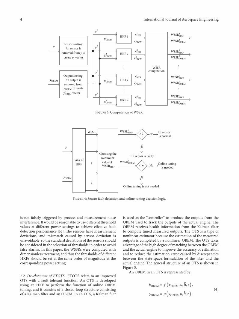
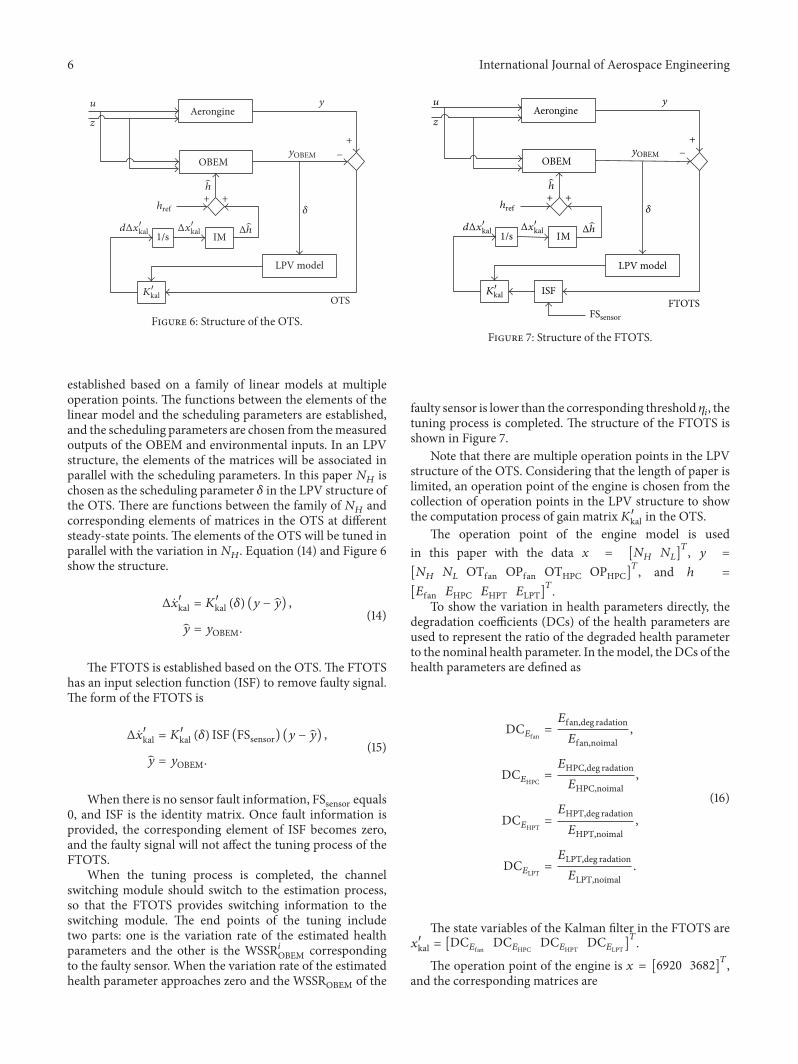
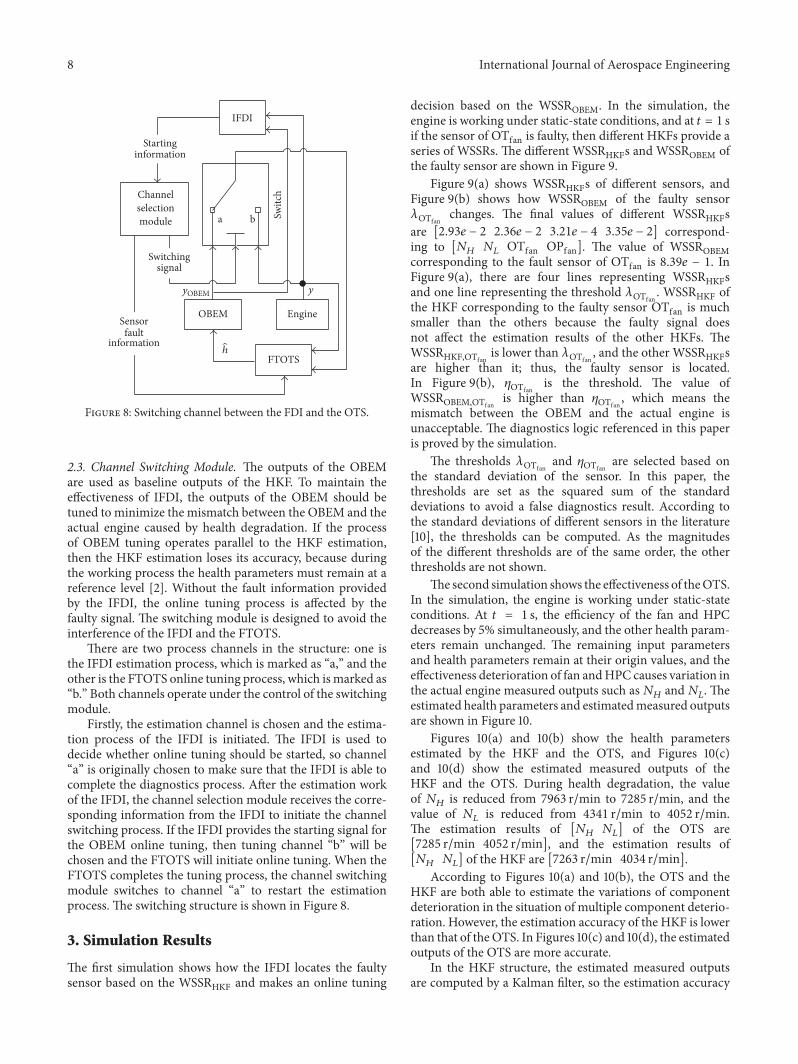
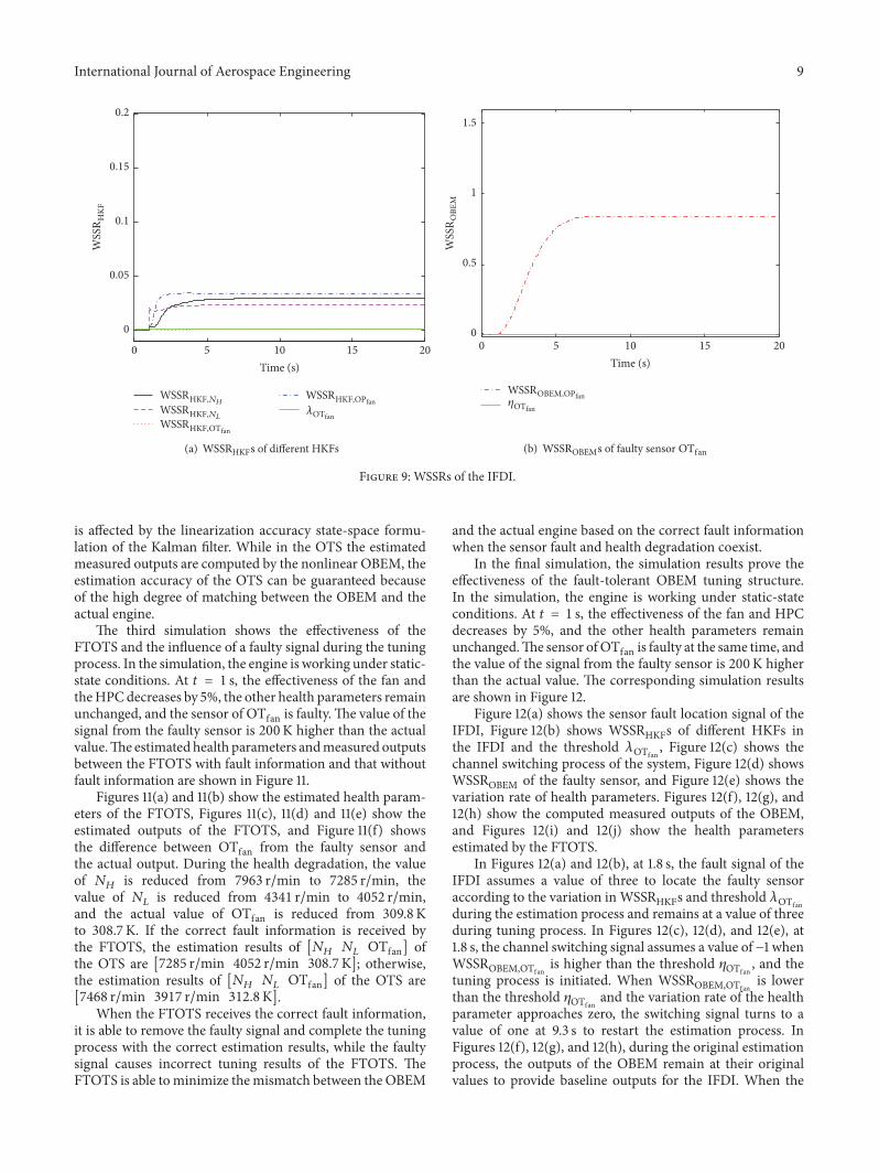
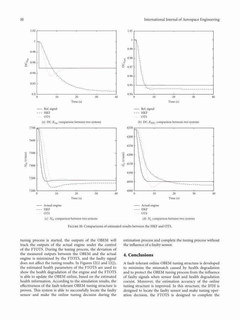
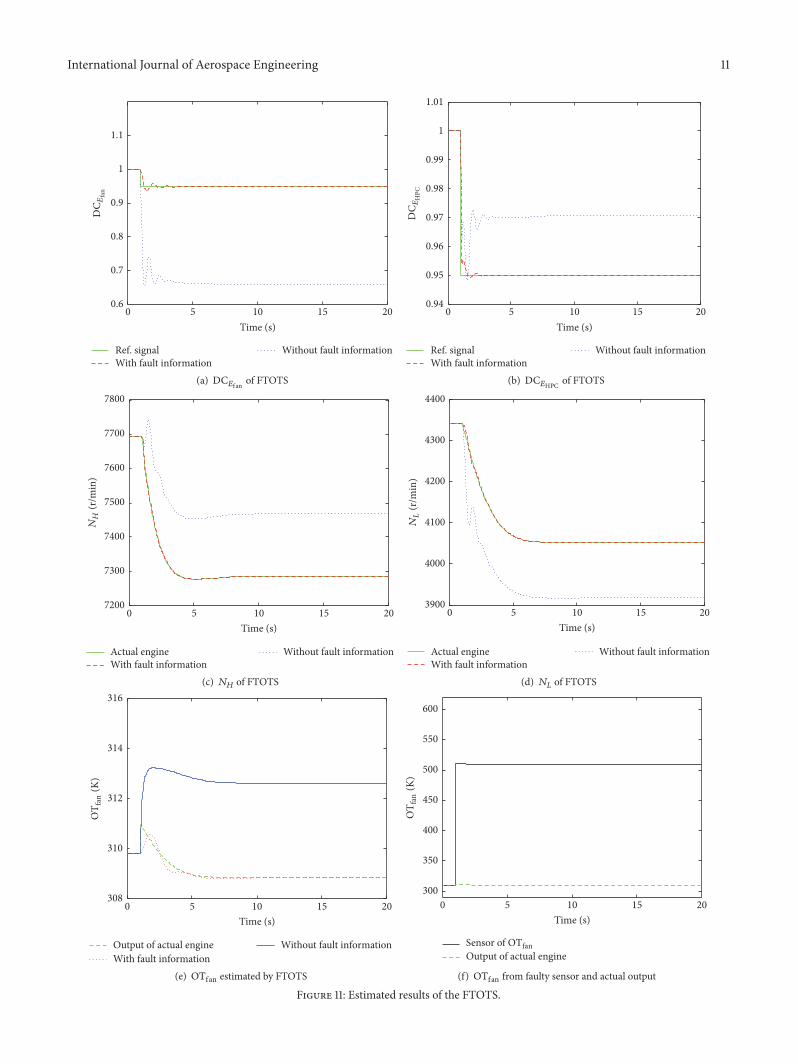
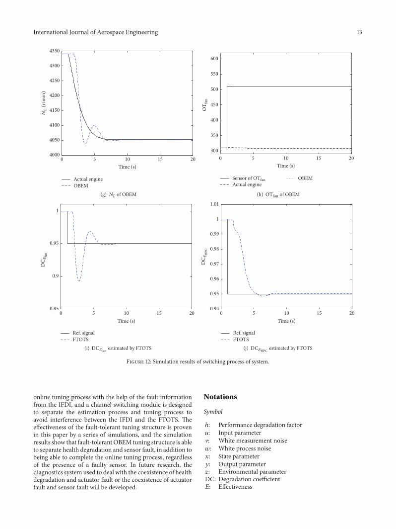

International Journal of
AerospaceEngineeringHindawi Publishing Corporationhttpwwwhindawicom Volume 2014
RoboticsJournal of
Hindawi Publishing Corporationhttpwwwhindawicom Volume 2014
Hindawi Publishing Corporationhttpwwwhindawicom Volume 2014
Active and Passive Electronic Components
Control Scienceand Engineering
Journal of
Hindawi Publishing Corporationhttpwwwhindawicom Volume 2014
International Journal of
RotatingMachinery
Hindawi Publishing Corporationhttpwwwhindawicom Volume 2014
Hindawi Publishing Corporation httpwwwhindawicom
Journal ofEngineeringVolume 2014
Submit your manuscripts athttpwwwhindawicom
VLSI Design
Hindawi Publishing Corporationhttpwwwhindawicom Volume 2014
Hindawi Publishing Corporationhttpwwwhindawicom Volume 2014
Shock and Vibration
Hindawi Publishing Corporationhttpwwwhindawicom Volume 2014
Civil EngineeringAdvances in
Acoustics and VibrationAdvances in
Hindawi Publishing Corporationhttpwwwhindawicom Volume 2014
Hindawi Publishing Corporationhttpwwwhindawicom Volume 2014
Electrical and Computer Engineering
Journal of
Advances inOptoElectronics
Hindawi Publishing Corporation httpwwwhindawicom
Volume 2014
The Scientific World JournalHindawi Publishing Corporation httpwwwhindawicom Volume 2014
SensorsJournal of
Hindawi Publishing Corporationhttpwwwhindawicom Volume 2014
Modelling amp Simulation in EngineeringHindawi Publishing Corporation httpwwwhindawicom Volume 2014
Hindawi Publishing Corporationhttpwwwhindawicom Volume 2014
Chemical EngineeringInternational Journal of Antennas and
Propagation
International Journal of
Hindawi Publishing Corporationhttpwwwhindawicom Volume 2014
Hindawi Publishing Corporationhttpwwwhindawicom Volume 2014
Navigation and Observation
International Journal of
Hindawi Publishing Corporationhttpwwwhindawicom Volume 2014
DistributedSensor Networks
International Journal of