requirements monitoring for an autonomic combat management … · combat management system (cms) of...
TRANSCRIPT

REQUIREMENTS MONITORING FOR AN AUTONOMIC
COMBAT MANAGEMENT SYSTEM
A FEASIBILITY STUDY
by Robert Westdijk
February 15, 2008


Faculty of Electrical Engineering, Mathematics and Computer Science Delft University of Technology
REQUIREMENTS MONITORING
FOR AN AUTONOMIC COMBAT MANAGEMENT SYSTEM
A FEASIBILITY STUDY
by
Robert Westdijk Student number: 1197886
Submitted for the degree of Master of Science
in Media and Knowledge Engineering
February 15, 2008
Graduation Committee: Dr. Drs. L.J.M. Rothkrantz
Ir. H.J.A.M. Geers Ir. P. Wiggers
Drs. A.V. van Leijen J. van der Weijden, MSc.
Abstract
Diagnosis of large and complex software systems is a challenging task that can highly benefit from monitoring of the high-level functional requirements. This research studies the potential of applying requirements monitoring for a software system of high complexity: the combat management system (CMS) of a modern and technological advanced naval platform. An effort is made to apply a monitoring technique that can be used for autonomizing of this system while limiting implementation impact. The goal of this thesis is to show the feasibility of using requirements monitoring in a CMS by presenting the design, implementation and simulation of a diagnostics expert system prototype. Additional uses such as software developer support and user assistance are also explored. The KAOS goal-oriented requirements engineering method is used to extract software system goals from previously documented requirements. With these high-level objectives as a starting point, the ReqMon requirements monitoring framework is applied. An implementation model is defined, identifying what data transformations are needed to apply the ReqMon system. This model is implemented as a prototype in a JESS development environment. Simulations show that detailed diagnosis of a complex software system as a CMS is feasible. They also demonstrate that the combination of requirements monitoring and rule-based reasoning provide a solid foundation for various levels of autonomy in an existing combat management system.

Master thesis February 15, 2008
Robert Westdijk page ii
Master thesis February 15, 2008
Robert Westdijk page iii
Acknowledgements This thesis marks the completion of a long journey (most will say too long) that has been my Master of Science program. After the completion of my training at the Royal Netherlands Naval College, which is now part of the Netherlands Defence Academy (NLDA), I have opted to continue my education at the Delft University of Technology. Much of my evening and weekend hours have been spent conducting the research presented in this thesis. My full-time assignment as a CMS Software Expert in the Test & Integration Team at the Centre for Automation of Mission- Critical Systems, CAMS/Force Vision has proven to be a busy occupation, slowing down research progress considerably. Finally, the thesis project has been completed, but I could not have done it alone. I would like to thank my supervisor at the NLDA, Drs. A.V. van Leijen, and my supervisor at the Faculty of Electrical Engineering, Mathematics and Computer Science, Dr. Drs. L.J.M. Rothkrantz for their guidance, and – considering my graduating period – patience. I would also like to thank my ex-supervisor at the Royal Netherlands Naval College, Ir. T.I.A. Simons, with whom it all started. I would like to thank my employer, CAMS/Force Vision at Den Helder, the Netherlands, for the time and resources I have been granted to finish the Media and Knowledge Engineering Master. Special thank goes out to Frank Zwarthoed, the developer and domain expert for the CMS Goalkeeper software, for his support. I would also like to express gratitude towards the members of Domain Maintenance for their assistance and feedback. Not in the least, I would like to thank Dr. William Robinson, the developer of the ReqMon framework, for his support. I hope my feedback to him was as helpful as his was to me. Finally, I thank my girlfriend for her support. Robert Westdijk, February 2008

Master thesis February 15, 2008
Robert Westdijk page iv

Master thesis February 15, 2008
Robert Westdijk page v
Abstract Diagnosis of large and complex software systems is a challenging task that can highly benefit from monitoring of the high-level functional requirements. This research studies the potential of applying requirements monitoring for a software system of high complexity: the combat management system (CMS) of a modern and technological advanced naval platform. An effort is made to apply a monitoring technique that can be used for autonomizing of this system while limiting implementation impact. The goal of this thesis is to show the feasibility of using requirements monitoring in a CMS by presenting the design, implementation and simulation of a diagnostics expert system prototype. Additional uses such as software developer support and user assistance are also explored. The KAOS goal-oriented requirements engineering method is used to extract software system goals from previously documented requirements. With these high-level objectives as a starting point, the ReqMon requirements monitoring framework is applied. An implementation model is defined, identifying what data transformations are needed to apply the ReqMon system. This model is implemented as a prototype in a JESS development environment. Simulations show that detailed diagnosis of a complex software system as a CMS is feasible. They also demonstrate that the combination of requirements monitoring and rule-based reasoning provide a solid foundation for various levels of autonomy in an existing combat management system.

Master thesis February 15, 2008
Robert Westdijk page vi

Master thesis February 15, 2008
Robert Westdijk page vii
Acronyms ADCF Air-Defense and Command Frigate AI Artificial Intelligence CAMS Centre for Automation of Mission-critical Systems CIWS Close-In Weapon System CMS Combat Management System GORE Goal-Oriented Requirements Engineering IBM International Business Machines corporation IDE Integrated Development Environment JESS Java Expert System Shell KAOS Knowledge Acquisition in AutOmated Specification NLDA Netherlands Defence Academy OCL Object Constraint Language OODA Observe, Orient, Act and Decide RE Requirements Engineering RNLN Royal Netherlands Navy SEWACO Combat Systems (Dutch: Sensor-, Wapen- en Commando systemen) SSADM Structured Systems Analysis and Design Method TUD Delft University of Technology UML Unified Modeling Language

Master thesis February 15, 2008
Robert Westdijk page viii

Master thesis February 15, 2008
Robert Westdijk page ix
Contents Acknowledgements ................................................................................................................. iii Abstract .................................................................................................................................... v Acronyms ............................................................................................................................... vii Contents .................................................................................................................................. ix List of figures and tables ......................................................................................................... xi
Figures ................................................................................................................................. xi Tables .................................................................................................................................. xi
1 Introduction ....................................................................................................................... 1 1.1 Problem description .................................................................................................. 1 1.2 Relevance ................................................................................................................. 1 1.3 Objectives ................................................................................................................. 2 1.4 Outline ...................................................................................................................... 2
2 Background ....................................................................................................................... 3 2.1 Guardion combat management system .................................................................... 3 2.2 Autonomic computing ............................................................................................... 3 2.3 Requirements monitoring ......................................................................................... 5 2.4 Requirements engineering ....................................................................................... 6 2.5 KAOS ........................................................................................................................ 7 2.6 ReqMon framework .................................................................................................. 8
3 Model ................................................................................................................................ 9 3.1 General approach ..................................................................................................... 9
3.1.1 Software monitoring .............................................................................................. 9 3.1.2 Diagnostic reasoning ............................................................................................ 9
3.2 Uses for requirements monitoring........................................................................... 10 3.3 Implementation model ............................................................................................ 11
3.3.1 Implementing the OODA loop ............................................................................. 11 3.3.2 Prototype implementation ................................................................................... 12
4 Implementation ................................................................................................................ 13 4.1 Requirements monitoring for the CMS ................................................................... 13
4.1.1 Goal elicitation .................................................................................................... 13 4.1.2 Goal specification ............................................................................................... 15 4.1.3 Monitor definition ................................................................................................ 17 4.1.4 Monitor compilation ............................................................................................. 18
4.2 Prototype implementation ....................................................................................... 18 4.2.1 Requirements monitoring prototype .................................................................... 18 4.2.2 Reasoner prototype ............................................................................................ 21 4.2.3 Prototype development environment .................................................................. 24 4.2.4 Knowledge elicitation process ............................................................................ 26
5 Results ............................................................................................................................ 29 5.1 Overview of results ................................................................................................. 29 5.2 Case 1: Supporting the developer .......................................................................... 29 5.3 Case 2: Informing the operator ............................................................................... 31 5.4 Case 3: Assisting the maintainer ............................................................................ 33 5.5 Case 4: Closing the loop ........................................................................................ 34
6 Discussion ....................................................................................................................... 37 7 Summary and conclusion ................................................................................................ 39 8 Recommendations .......................................................................................................... 41 9 References ...................................................................................................................... 43 Annex 1: Research paper ....................................................................................................... 45 Annex 2: Paper award ............................................................................................................ 57 Annex 3: Research report ...................................................................................................... 59 Annex 4: Software component diagram ................................................................................. 81

Master thesis February 15, 2008
Robert Westdijk page x
Master thesis February 15, 2008
Robert Westdijk page xi
List of figures and tables
Figures Figure 2.1: The OODA loop for self-healing. page 5 Figure 2.2: Data streams for a software component monitored by a ReqMon
daemon. page 8
Figure 3.1: Data flow of diagnostic information in the requirements monitoring system.
page 10
Figure 3.2: Implementation of the OODA loop for self-healing. page 11 Figure 3.3: Steps for implementing requirements monitoring using ReqMon. page 12 Figure 4.1: Goal graph for the “Sea Control” capability statement. page 14 Figure 4.2: Goal graph for the CMS diagnostic software suite. page 14 Figure 4.3: Partial goal graph of the diagnostic suite for the navigation radars. page 16 Figure 4.4: Example goal structures for the diagnostic suite for the navigation
radars. page 16
Figure 4.5: The Dwyer temporal pattern scopes. page 17 Figure 4.6: Software coordination model for the CMS Navigation Radar
diagnostic software chain. page 18
Figure 4.7: An example of ReqMon output. page 21 Figure 4.8: Software coordination model for the CMS Goalkeeper software
chain. page 21
Figure 4.9: Partial KAOS goal graph for the Goalkeeper system. page 22 Figure 4.10: Information flow in the monitoring and reasoning framework, with a
simple pseudo-code example. page 22
Figure 4.11: Screenshot of the development environment. page 25 Figure 4.12: Resulting output for a OCL message type test scenario. page 26 Figure 5.1: Example of a possible error pop-up for a Goalkeeper operator. page 32 Figure 5.2: Example output from a JESS simulation. page 33 Figure 5.3: Example of a possible reconfiguration plan for the “no-own-ship-
data” failure. page 35
Tables Table 2.1: Self-properties of autonomic systems. page 4 Table 4.1: Standardized OCL message types for monitor definition. page 19

Master thesis February 15, 2008
Robert Westdijk page xii

Master thesis February 15, 2008
Robert Westdijk page 1
1 Introduction In this chapter, the subject of this thesis is presented. The problem is described in Section 1.1. In Section 1.2, the relevance of this problem is explained and in Section 1.3 the objectives are stated. Section 1.4 will outline this thesis.
1.1 Problem description Nowadays, naval ships are becoming technologically more advanced due to a higher level of automation and the growing potential of the onboard sensor suite. This results in combat management systems (CMS) becoming more and more complex. The CMS of a navel vessel is the collection of hardware and software integrating the so-called SEWACO subsystems, which are the combat systems necessary for performing the various operational tasks. While the complexity of the subsystems and software increases with every new type of ship, reductions in staff result in fewer personnel available to operate and manage the CMS software. This paradox of increased complexity versus reduced manning is one of the reasons to search for novel techniques to support the software maintainer onboard. The research presented in this thesis focuses on the application of requirements monitoring for software maintainer support and as a basis for the implementation of autonomic computing.
1.2 Relevance Self-management of software systems and the related subject of autonomic computing is a relatively new research area in component-based software engineering and Artificial Intelligence (AI). It refers to systems that can manage themselves given high-level objectives [16]. Self-management means that the system should be able to monitor its behavior, reason about the data extracted by monitoring and if necessary adapt itself accordingly. To enable an autonomic system to modify its own behavior, the system must have knowledge about what its required behavior is. For many systems the behavior can be described by means of a system model. However, creating a model of a complex software system is extremely difficult. It is commonly accepted that software systems have grown too large to statically verify and analyze [35]. Such an endeavor would require disproportionate time and resources in the development process of a system and would be even more difficult to apply on already developed systems. To limit the design and development impact, the use of requirements monitoring is proposed. This monitoring technique eliminates the need for a comprehensive system model. In general, the utilization of requirement monitoring introduces the following advantages:
1. The opportunity to model system behavior on a high level without the creation of a complex behavioral model.
2. A limitation of implementation workload required by designers and developers. 3. An approach to streamline the requirements elaboration process.
While much literature concerns the design of a new requirements monitoring framework, the emphasis of this work is more on implementing a requirements monitoring system in an existing software system. To show how requirements monitoring can be implemented and

Master thesis February 15, 2008
Robert Westdijk page 2
that it can serve as a basis for applying autonomic computing, the CMS as found on board the Dutch air-defense and command frigates (ADCF) is used as an implementation test bed.
1.3 Objectives The goal of this research is to give a first impulse for the automation and autonomization of the CMS software management tasks. The main objectives are:
1. To define a model for the implementation of an AI diagnostic expert system based on requirements monitoring.
2. To create a test environment for simulating and testing of the implementation model. 3. To develop a requirements monitoring prototype as a proof of concept.
1.4 Outline This thesis is organized as follows. First, some background information is provided in Chapter 2 about autonomic computing and requirements monitoring. Then Chapter 3 presents the model for requirements monitoring implementation. After that, the implementation of the requirement monitoring framework and diagnostic reasoning component are discussed in Chapter 4. The paper [37] found in Annex 1 is mainly based on this chapter. The results acquired by tests with these prototypes are presented in Chapter 5. The report [38] found in Annex 3 is mainly based on this chapter. Finally, the conclusions of this thesis are presented in Chapter 6.

Master thesis February 15, 2008
Robert Westdijk page 3
2 Background This chapter discusses related work and provides some background to the thesis problem. First, Section 2.1 introduces the Guardion combat management system. Section 2.2 then discusses the concept of autonomic computing. Section 2.3 deals with requirements monitoring. The related subject of requirements engineering is discussed in Section 2.4. Finally, Sections 2.5 and 2.6 describe the KAOS approach and the ReqMon monitoring framework.
2.1 Guardion combat management system The CMS of a naval vessel is the collection of hardware and software which integrates the SEWACO subsystems, which are necessary for performing the various operational tasks of the vessel. The following functions are generally performed by the CMS:
1. Data handling 2. Information handling 3. Communication control 4. Message handling 5. System monitoring and control 6. Weapon control.
The non-physical part of the CMS consists of the software that performs the diversity of functions mentioned above. In this thesis, the emphasis is on the software part of the CMS. The Royal Netherlands Navy (RNLN) has aimed for integrated combat systems to allow central operation of the ship’s subsystems, which eventually led to the use of generic all-purpose workstations in the Operations Room. The CMS software for Dutch naval ships is developed at the Centre for Automation of Mission-critical Systems (CAMS/Force Vision) in Den Helder, The Netherlands. The CMS software of a modern naval vessel is a good example of a complex software system. It is a highly integrated software system that is both network-based and component-based. CAMS/Force Vision invests in research and development of software management tools to support maintenance at sea, taking into account the paradox of increased complexity versus reduced manning. Beside the development of software support tools for the system’s maintainers, completely autonomizing the system is also an issue of interest.
2.2 Autonomic computing An autonomic software system should be able to modify its own behavior in order to adapt itself given high-level objectives and must be able to manage itself, hence the name “self”-systems for systems that have this ability. There are four main aspects of autonomic computing: self-configuration, self-optimization, self-healing and self-protection [18]. Two more features are mentioned in [34]: self-organization and self-adaptation. This thesis focuses on the ability of self-healing, meaning that the system can examine, find, diagnose and react to system malfunctions [22]. Autonomic computing is a relatively new research topic and is a hot issue in software engineering. This is because of the manifesto and the vision on autonomic computing that have been released by IBM [16] in which autonomic computing is introduced. However, [21] points out that the concept of self-managing and self-adapting systems is not new.

Master thesis February 15, 2008
Robert Westdijk page 4
Summarizing, The following self-properties can be identified [16], [18], [34], which are defined shortly in Table 2.1:
1. Self-configuration 2. Self-optimization 3. Self-healing 4. Self-protection 5. Self-organization 6. Self-adaptation.
Table 2.1: Self-properties of autonomic systems, adapted from [16], [18] and [34].
Self-property Description
Self-configuring The automated configuration of components and systems following high-level policies.
Self-optimization The automated improvement of the performance and efficiency of systems and components.
Self-healing The automated detection, diagnoses and repair of software and hardware problems. Self-protection The automated defense against attacks or cascading failures. Self-organization The autonomous reconfiguration of interactions among components. Self-adaptation The automated change of behavior in reaction to changes in the working
environment.
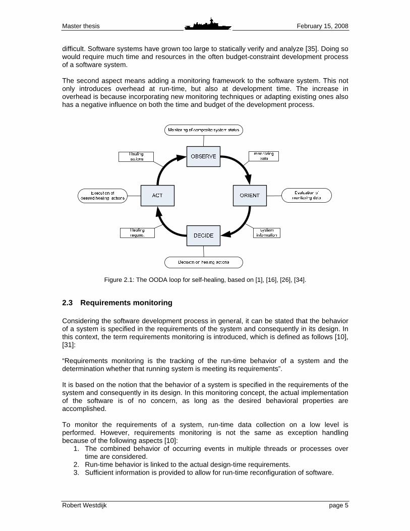
It is clear that all these self-properties are related to each other and have a tendency to overlap. For instance, the terms self-configuring and self-organization seem the same. However, the first refers to the configuration of a system, while the latter is related to the architectural constraints of a system. Furthermore, a self-system is by definition self-adaptive, since it changes certain properties or elements of itself due to some influence. However, the self-adaptation property is introduced to make a clear distinction between internal and external influences. This thesis focuses on the ability of self-healing, meaning that the system can examine, localize, diagnose and react to system malfunctions. The process of self-management implements a control loop [1], [16], [26], [34]. The OODA loop can be applied here, which is a concept that is generally used for strategic military purposes. It identifies four phases: Observe, Orient, Decide, and Act. These phases are applied to the self-healing autonomic computing concept. This leads to the phases as depicted in Figure 2.1 and as described below:
1. The observation phase is the process of monitoring and data collection. This data could originate from the system itself, but it can also be data from the external environment in which the system operates.
2. The orient phase features the analysis and interpretation of the collected data. The collected data should be transformed into information, which can be related to the high-level goals set for the self-managing system.
3. The decide phase is the phase in which the system may decide that action on its behalf is needed. Here, the information from the orient phase is used. Generally, a reconfiguration plan is created.
4. The act phase executes the healing actions that are needed, for instance based on a reconfiguration plan. The executed actions should bring the system from the current state to the desired state.
An autonomic computing system must be able to modify its own behavior. In order to accomplish this, the system must have knowledge about what its required behavior is. Therefore, the required system behavior must be defined, and that the system should be enabled to monitor this behavior. Both aspects introduce some form of overhead. The first aspect involves the creation of some kind of system model. However, creating an accurate behavioral model of complex software systems such as the CMS is extremely
Master thesis February 15, 2008
Robert Westdijk page 5
difficult. Software systems have grown too large to statically verify and analyze [35]. Doing so would require much time and resources in the often budget-constraint development process of a software system. The second aspect means adding a monitoring framework to the software system. This not only introduces overhead at run-time, but also at development time. The increase in overhead is because incorporating new monitoring techniques or adapting existing ones also has a negative influence on both the time and budget of the development process.
Figure 2.1: The OODA loop for self-healing, based on [1], [16], [26], [34].
2.3 Requirements monitoring Considering the software development process in general, it can be stated that the behavior of a system is specified in the requirements of the system and consequently in its design. In this context, the term requirements monitoring is introduced, which is defined as follows [10], [31]: “Requirements monitoring is the tracking of the run-time behavior of a system and the determination whether that running system is meeting its requirements”. It is based on the notion that the behavior of a system is specified in the requirements of the system and consequently in its design. In this monitoring concept, the actual implementation of the software is of no concern, as long as the desired behavioral properties are accomplished. To monitor the requirements of a system, run-time data collection on a low level is performed. However, requirements monitoring is not the same as exception handling because of the following aspects [10]:
1. The combined behavior of occurring events in multiple threads or processes over time are considered.
2. Run-time behavior is linked to the actual design-time requirements. 3. Sufficient information is provided to allow for run-time reconfiguration of software.

Master thesis February 15, 2008
Robert Westdijk page 6
The last aspect links the executing of monitoring requirements to the autonomization of software systems. In the view of [10], automatic run-time monitoring is a key step towards making system self-evolving. The link between autonomic computing and requirements monitoring is also underlined by [19], stating that requirements and their subsequent requirements goal models can be used as a foundation for software that incorporates autonomic computing.
2.4 Requirements engineering A prerequisite for conducting requirements monitoring is the formalization of those requirements [19], [29]. This is part of the process of Requirements Engineering (RE). RE is concerned with the identification and refinement of goals, the operationalization of the refined goals and the assignment of responsibilities for the resulting requirements [6]. A more elaborate definition is given in [23]: “Requirements engineering is the branch of software engineering concerned with the real-world goals for functions of and constraints on software systems. It is also concerned with the relationship of these factors to precise specifications of the software behavior, and their evolution over time and across software families.” In the software development process, the term “requirement” is often used for required behavior or functionality throughout the various abstraction levels of the system design. The following definitions with regard to the term requirement can be distinguished in literature [29]:
1. Goal, which is a desired property of the software and its environment. 2. Requirement, which refines a goal by satisfying three properties:
a. It is described entirely in terms of values monitored by the software. b. It contains only values that are controlled by the software. c. The controlled values are not defined in terms of future monitored values.
3. Policy, which is a goal that: a. Is abstract and broadly scoped. b. Addresses societal values. c. Requires human interpretation.
Below, the core activities of the RE process are identified [17], [23]. These activities are roughly ordered chronically here, but are mostly intertwined:
1. Domain analysis 2. Knowledge elicitation 3. Specification 4. Specification analysis 5. Communication 6. Negotiation and agreement 7. Evolution.
Generally, RE is said to have two main phases. The first is the early requirements phase, which concentrates on the analysis and modeling of the environment of the system, the organisation and stakeholders, and the objectives and relationships of these stakeholders. The domain analysis and elicitation activities are conducted in this phase. The second phase, called the late requirements phase, is concerned with the modeling the composite system. Mainly specification activities are executed in this phase. A more elaborate description of the requirement engineering processes can be found in [36].

Master thesis February 15, 2008
Robert Westdijk page 7
2.5 KAOS Traditional system analysis methods in requirements engineering such as SSADM (Structured Systems Analysis and Design Method) are inadequate when dealing with complex software systems [18]. The main reasons for this are:
1. The lack of support for formal reasoning about the composite system. 2. The inability to cope with non-functional requirements, which are requirements that
represent system qualities or properties as a whole, for instance the maintainability of a system.
3. The inability of representing and comparing alternative system configurations. The Goal-Oriented Requirements Engineering (GORE) approach attempts to solve these problems. GORE focuses on activities that precede the specification phase in the traditional RE process. It aims for less emphasis on the question how a software system should operate and more on why a system is needed. GORE approaches provide a breakdown of the composite system requirements into operationalizable goals. These goals provide a basis for requirements monitoring, identifying what part of the system is responsible for what goal. The GORE method KAOS (Knowledge Acquisition in AutOmated Specification) is a frequently used technique in RE processes and requirements monitors development. The use of KAOS in this thesis project is adopted based on the conclusions of a literature study [36]. The main advantages over other GORE methods are:
1 Research and documentation on the KAOS methodology can easily be acquired. 2 Various tools exist that support the sub process and steps within the KAOS method
(e.g., [3], [24]). 3 KAOS uses object models, which can be represented using for instance UML (Unified
Modeling Language) [14]. The KAOS methodology mainly utilizes formal analysis techniques. It combines semantic nets and implements linear-time temporal logic to formalize and express the goals and other objects of the system [18]. Objects in KAOS are things of interest in the system, whose instances can evolve from state to state. Objects can be entities, relationships or events. Operations are input-output relations over these objects. They can define state transitions and are declared by signatures over objects. Operations have pre, post and trigger conditions. In essence, KAOS strives to describe the functionally of a system in terms of goals. A goal can lead to one or more requirements. These goals should be operationalized by an agent1, which is an entity it the composite system. Operations on objects are performed by agents, which act as the processor for these operations. Agents are active components that can be humans, devices, software, etc. An agent in a software system can for instance be a specific software component or a part of the infrastructure. Goals are refined in hierarchies using “AND” and “OR” relations. Goal refinement ends when an individual agent operationalizes a sub goal. The relations between goals and agents can be visualized in a graph. Goal graphs offer a good overview of which elements of the system are responsible for certain tasks. They are scalable in size, for instance zooming in on parts of the system, and in depth, for instance by using general goals or really specific goals.
1 A KAOS agent does not have the same qualifications as agents in AI research. KAOS agents can be any active component in the composite system, such as humans, devices or software.
Master thesis February 15, 2008
Robert Westdijk page 8
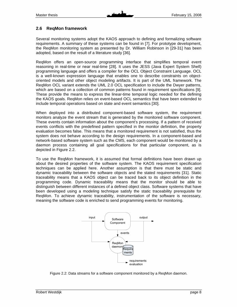
2.6 ReqMon framework Several monitoring systems adopt the KAOS approach to defining and formalizing software requirements. A summary of these systems can be found in [7]. For prototype development, the ReqMon monitoring system as presented by Dr. William Robinson in [29-31] has been adopted, based on the result of a literature study [36]. ReqMon offers an open-source programming interface that simplifies temporal event reasoning in real-time or near real-time [28]. It uses the JESS (Java Expert System Shell) programming language and offers a compiler for the OCL Object Constraint Language. OCL is a well-known expression language that enables one to describe constraints on object-oriented models and other object modeling artifacts. It is part of the UML framework. The ReqMon OCL variant extends the UML 2.0 OCL specification to include the Dwyer patterns, which are based on a collection of common patterns found in requirement specifications [9]. These provide the means to express the linear-time temporal logic needed for the defining the KAOS goals. ReqMon relies on event-based OCL semantics that have been extended to include temporal operations based on state and event semantics [30]. When deployed into a distributed component-based software system, the requirement monitors analyze the event stream that is generated by the monitored software component. These events contain information about the component’s processing. If a pattern of received events conflicts with the predefined pattern specified in the monitor definition, the property evaluation becomes false. This means that a monitored requirement is not satisfied, thus the system does not behave according to the design requirements. In a component-based and network-based software system such as the CMS, each component would be monitored by a daemon process containing all goal specifications for that particular component, as is depicted in Figure 2.2. To use the ReqMon framework, it is assumed that formal definitions have been drawn up about the desired properties of the software system. The KAOS requirement specification techniques can be applied here. Another assumption is that there must be static and dynamic traceability between the software objects and the stated requirements [31]. Static traceability means that a KAOS object can be traced back to its object definition in the programming code. Dynamic traceability means that the monitor should be able to distinguish between different instances of a defined object class. Software systems that have been developed using a modeling technique satisfy the static traceability prerequisite for ReqMon. To achieve dynamic traceability, instrumentation of the software is necessary, meaning the software code is enriched to send programming events for monitoring.
Software
Component
ReqMon
daemon
input output
events
Require
ments
requirements
evaluation
Figure 2.2: Data streams for a software component monitored by a ReqMon daemon.

Master thesis February 15, 2008
Robert Westdijk page 9
3 Model In this chapter, the proposed implementation for requirements monitoring is discussed. Section 3.1 explains this model in general terms. The related data flows are described in Section 3.2. The actual implementation model using the KAOS and ReqMon approaches is presented in Section 3.3.
3.1 General approach
3.1.1 Software monitoring The main goal of this research is to give a first impulse for the automation and autonomization of the CMS software management tasks. Section 2.2. presented the OODA-loop as a tool to identify the main steps in autonomic computing. To accomplish this, the use of requirements monitoring as a monitoring approach was proposed by a literature study [36]. The main benefits of this technique are:
1. The ability of describing system behavior without the creation of a complex behavioral model.
2. The limited strain and influence on the work of software designers and developers. 3. Its testability for the current version of the Guardion CMS. 4. Its use of formal requirements specification offers an approach to streamline the
requirements elaboration process in future CMS development. To implement requirements monitoring, the requirements should somehow be formalized. The use of a GORE method is proposed here. GORE approaches provide a breakdown of the composite system requirements into operationalizable goals. These goals provide a basis for requirement monitoring, because it is made clear what part of the system is responsible for the operationalization of certain system goals. Thus, GORE can be used as preliminary step in the development of a requirements monitor. For new software systems, the goal-elicitation phase should be incorporated in the design phase. By refining the goals and assigning them to the responsibility of an agent, the lower-level requirements statements can be created. This serves as a basis for the creation of the monitor definitions for the requirements monitoring system. In essence, the implementation will be done following a top-down approach. If the requirements monitoring framework is implemented in an existing software system, the requirement engineering process will already have been completed. The software will be already developed. In this case, a bottom-up implementation strategy should be chosen. Existing requirement and technical documentation should be used to construct the formalizations needed for the requirements monitor definitions.
3.1.2 Diagnostic reasoning The software monitors defined by using the requirements monitoring approach are the basis for further diagnostic reasoning. By deploying the monitors, it can be detected whether the requirements for certain software components are met. In case the requirements are not satisfied, the cause for this fault should be localized. Some sort of diagnostic reasoning is to be used, implying that diagnostic knowledge must be added to the monitoring system.

Master thesis February 15, 2008
Robert Westdijk page 10
Requirements monitoring has been chosen as a monitoring technique because it reduces the need for adding domain specific knowledge to the monitors. However, for the creation of fault hypotheses when requirements become unsatisfied during software execution, diagnostic knowledge of the monitored system must be available. The advantage here is, that reasoning can be done on a higher and more understandable level using the available information from the requirements monitors. Instead of reasoning on the level of the actual programming code, it will be based on the requirement properties that have been evaluated by these monitors. However, domain expert knowledge must still be acquired and implemented in the monitoring and reasoning system. To ascertain the fault diagnosis, a simple AI rule-based expert system approach is adopted as a proof of concept. The programming event property evaluations from multiple requirements monitors are combined into knowledge rules. The combination of these properties provide information about the specific cause of a problem. The impact of this problem on the system’s functionality will already be clear, since certain requirements will no longer be satisfied.
3.2 Uses for requirements monitoring In this research project, the use of requirements monitoring is proposed as a basis for performing autonomic computing. The information gathered by the requirements monitors is used for further diagnostic reasoning. However, requirements monitoring can have more uses, both during the software development as well as during run-time software execution. These uses are reviewed here. Figure 3.1 depicts these uses as well. During the software development phase, the monitoring framework enables the software developer to define requirements monitor specifications. Based on these specifications, the monitors will evaluate the event stream that is generated by the software. When a pattern of events is detected that indicate that a requirement is unsatisfied, an alert can be issued. This information can be valuable in the process of software testing. The requirement monitors can detect requirements that are unsatisfied. In turn, the developer can correct the detected problem by analyzing the unwanted event pattern and make the necessary changes accordingly. When the requirement monitoring framework is deployed in a software system, the monitors will constantly evaluate the required behavior of the system. This information can be used to provide the users with feedback about system performance and possible errors. For instance, when a requirement becomes unsatisfied, a user warning can be issued. This warning can be displayed on the screen. The user can then correct the problem, or contact the system administrators.
Figure 3.1: Data flow of diagnostic information in the requirements monitoring system.
Master thesis February 15, 2008
Robert Westdijk page 11
3.3 Implementation model
3.3.1 Implementing the OODA loop This thesis focuses on the an existing software system, the Guardion CMS. The requirements for this system and its software components have already been drawn up. This calls for a bottom up goal definition strategy, which means that the stated software requirements should be used to create formalized goals. New goals may be added if necessary. The extracted goals will be used to form sub goals of higher level goals, keeping in mind the existing operation capabilities and the staff requirements. Since goals and requirements are so closely related, these terms will be used as synonyms in the rest of this paper. The GORE method of KAOS will be used for creating the goal definitions, which is a frequently used technique in requirements engineering processes and requirements monitors development. This GORE method is discussed in more detail in Section 2.5, in which the main advantages of this approach were identified:
1. Research and documentation on the KAOS methodology can easily be acquired. 2. Various tools exist that support the sub process and steps within the KAOS method
(e.g., [3], [24]). 3. KAOS uses object models, which can be represented using for instance UML (Unified
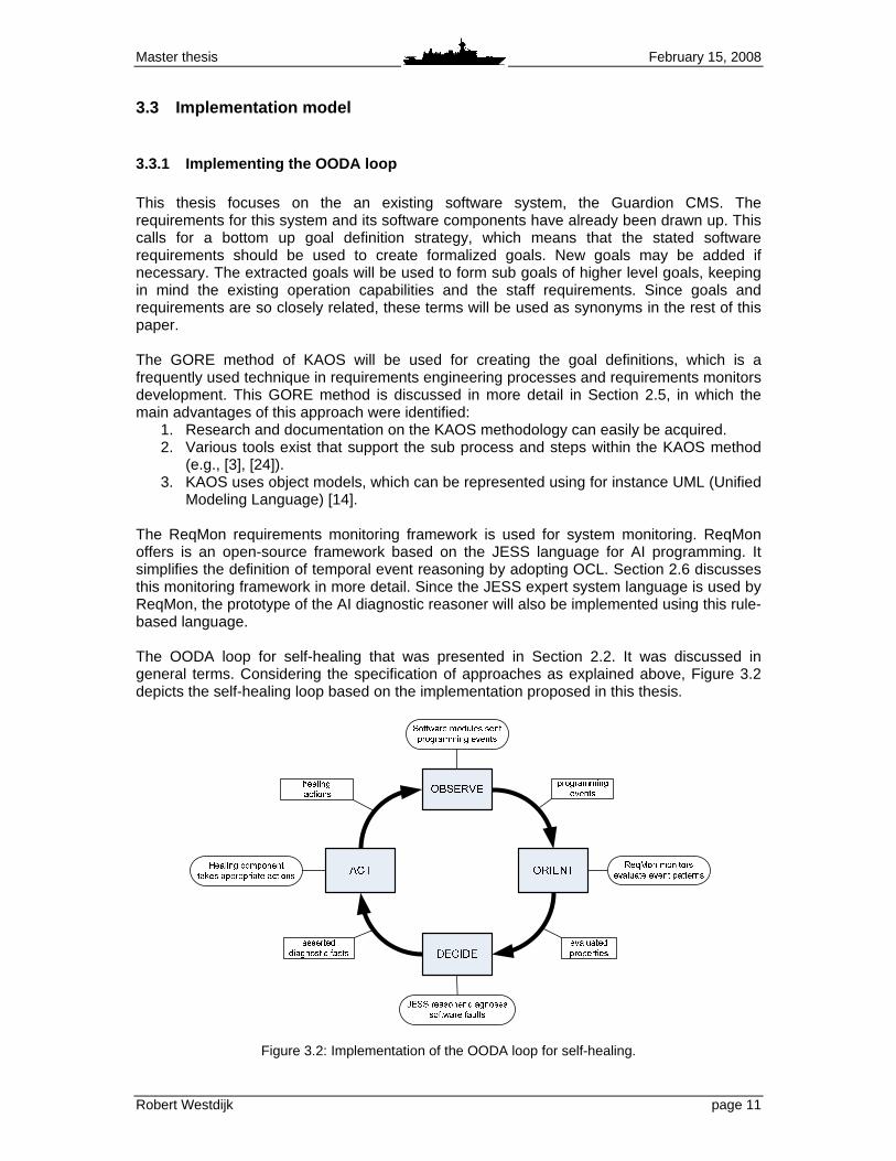
Modeling Language) [14]. The ReqMon requirements monitoring framework is used for system monitoring. ReqMon offers is an open-source framework based on the JESS language for AI programming. It simplifies the definition of temporal event reasoning by adopting OCL. Section 2.6 discusses this monitoring framework in more detail. Since the JESS expert system language is used by ReqMon, the prototype of the AI diagnostic reasoner will also be implemented using this rule-based language. The OODA loop for self-healing that was presented in Section 2.2. It was discussed in general terms. Considering the specification of approaches as explained above, Figure 3.2 depicts the self-healing loop based on the implementation proposed in this thesis.
Figure 3.2: Implementation of the OODA loop for self-healing.
Master thesis February 15, 2008
Robert Westdijk page 12
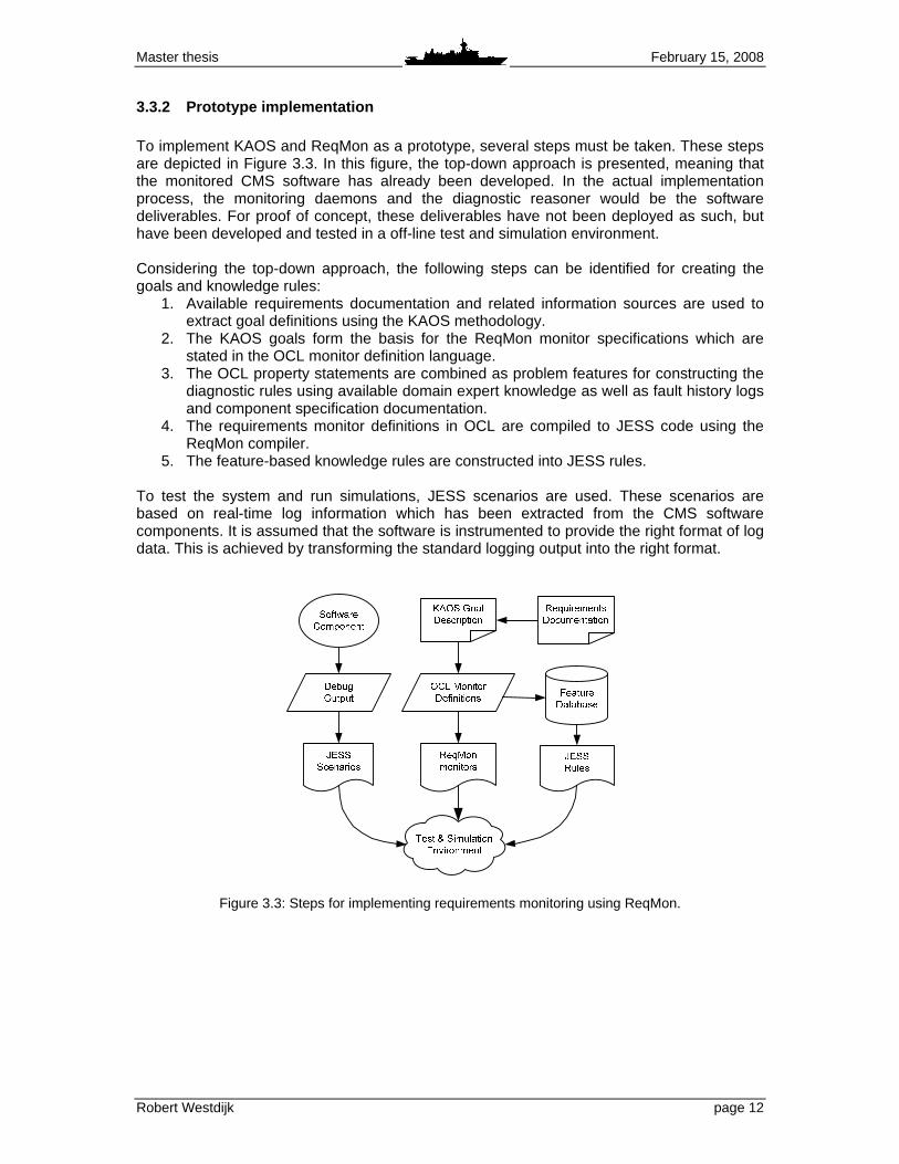
3.3.2 Prototype implementation To implement KAOS and ReqMon as a prototype, several steps must be taken. These steps are depicted in Figure 3.3. In this figure, the top-down approach is presented, meaning that the monitored CMS software has already been developed. In the actual implementation process, the monitoring daemons and the diagnostic reasoner would be the software deliverables. For proof of concept, these deliverables have not been deployed as such, but have been developed and tested in a off-line test and simulation environment. Considering the top-down approach, the following steps can be identified for creating the goals and knowledge rules:
1. Available requirements documentation and related information sources are used to extract goal definitions using the KAOS methodology.
2. The KAOS goals form the basis for the ReqMon monitor specifications which are stated in the OCL monitor definition language.
3. The OCL property statements are combined as problem features for constructing the diagnostic rules using available domain expert knowledge as well as fault history logs and component specification documentation.
4. The requirements monitor definitions in OCL are compiled to JESS code using the ReqMon compiler.
5. The feature-based knowledge rules are constructed into JESS rules. To test the system and run simulations, JESS scenarios are used. These scenarios are based on real-time log information which has been extracted from the CMS software components. It is assumed that the software is instrumented to provide the right format of log data. This is achieved by transforming the standard logging output into the right format.
Figure 3.3: Steps for implementing requirements monitoring using ReqMon.

Master thesis February 15, 2008
Robert Westdijk page 13
4 Implementation This chapter discusses the design and implementation of requirements monitoring based on the presented model. Section 4.1 discusses the general implementation for the CMS, while the implemented prototypes are presented in Section 4.2.
4.1 Requirements monitoring for the CMS In Section 3.3, the design and implementation model was discussed for the implementation of requirements monitoring in the Guardion CMS. In general, the following steps must be carried out to apply the ReqMon requirements monitors:
1. The goals of the monitored system are identified using the KAOS goal-oriented RE approach.
2. The defined goals are specified into requirement statements. 3. The ReqMon monitors are defined based on the goal specifications. 4. The monitor definitions are compiled to JESS code for use in the simulation
environment.
4.1.1 Goal elicitation For the creation the ReqMon monitors, first the goals of a software component should be identified. The KAOS requirement engineering approach is applied here. The general idea is that the functionality of the composite system is described in terms of goals that should be achieved. These goals should be operationalized by agents, which are entities within the composite system. Agents can be humans, devices, software, etc. Goal graphs are used to visualize the relation between goals and agents. This gives an overview of the responsibility of system elements for certain tasks. Goal graphs are scalable in both size and depth. It is possible to create goal graphs for various parts of the system, and on various levels of detail. To illustrate how goals and goal graphs work, two example figures are presented. In the goal graphs presented in this thesis, the goals are represented by parallelograms. The agents will be presented by octagons. Furthermore, a black dot represents an “AND” hierarchy, while a white dot represents an “OR” relation between the goals. The first example is a high-level goal graph which is extracted from the staff requirements document for the Dutch ADCF naval vessels [27], depicted in Figure 4.1. In this particular example, the “Sea Control” capability statement is presented. It illustrates how agents (in this case: weapon systems) can be assigned to the various goals stated for a modern naval vessel. The second example is depicted in Figure 4.2 and shows a general goal graph for a the diagnostic software suite implemented in the CMS. It shows how system goals can be translated into the assignment of functionality to a specific group of generic CMS software components2.
2Most details of this military software system are classified. In the context of the research presented in this thesis, it is sufficient
to mention only the abbreviations of the software components without further comment.

Master thesis February 15, 2008
Robert Westdijk page 14
Sea control
is provided
Anti Air
Warfare can
be deployed
Anti Surface
Warfare can
be deployed
Anti Sub-suface
Warfare can be
deployed
MK41 Vertical
Launch System
AAW Aircraft
Control System
Goalkeeper
Decoy Launch
System
ASW Aircraft
Control System
MK46 Torpedo
Weaponsystem
NH-90 Helicopter
Harpoon Missile
System
Local Area SAM
Missiles can be
launched
Electronic
countermeasures
can be deployed
Incoming missiles
at short range can
be engaged
AAW aircraft
can be
controlled
Medium Range
SAM Missiles
can be launched
ASW aircraft can
be controlled
Torpedos can
be launched
Remote sub-surface
engagements can
be deployed
Gun Oto-Breda
Surface-to-
surface missiles
can be launched
Over-the-horizon
targeting can be
deployed
Naval gunfire
support can
be provided
Figure 4.1: Goal graph for the “Sea Control” capability statement.
Diagnostic
information is
provided
Functional
information is
provided
Diagnostic data
is extracted
from subsystem
Diagnostics
data is
interpreted
Diagnostic data
is converted to
information
Diagnostic information
is presented to the
maintainer
Remote
diagnostics is
provided
PCSE
MATRIX
PFDPFDFEU
CODIAG
Figure 4.2: Goal graph for the CMS diagnostic software suite.

Master thesis February 15, 2008
Robert Westdijk page 15
4.1.2 Goal specification In Section 2.4, the difference between a goal and a requirement was mentioned. Recapitulating, a goal identifies a desired property of the software and its environment, while a requirement refines a goal and should be described exclusively in terms of values controlled and monitored by the software. In practice, goals and requirements are often used as synonyms, because the stated requirements for a requirement statement are very rigid and are almost never met. In [30], Robinson points out: “Although goals are widely recognized as important, their use in object-oriented modeling is rare – particularly, with the UML methodology”. To achieve consistency and clarity in the goal statements, goal structures are used. These goals structures are based on the formal KAOS goal structure, of which examples can be found in for instance [7], [14], [20], [24]. The formal structures have been adapted to make them more suitable for use in requirements monitoring. For instance, the formal KAOS approach to goal names has been replaced by the use of human readable sentences, which is more in accordance with the common way to specify software requirements. Furthermore, informal OCL definitions are added to the goal structures. These are the definitions for monitoring of the goal. KAOS also offers a temporal specification language to define goal statements. However, it has been opted to use only informal goal definitions within the structures. This is because ReqMon itself offers an OCL language to formalize the goals. In this manner, the overhead for the software developer who has to define the goal statements is minimized. Summarizing, an adapted, less formal version of the KAOS goal structures is adopted in this research. This goal structure generally looks like: SystemGoal Goal statement
InformalDef Description of the goal statement ReducedTo
If a goal has sub goals, these are listed here GoalPattern
Pattern as defined by the KAOS method; defined patterns are Achieve, Maintain, Avoid and Cease
Concerns Identifies which objects play a role in the OCL definitions OclInformalDef
Description of the OCL definition for monitoring of this goal,
more definitions can be added when required . The goal structure specification forms the starting point for monitor implementation. Each informal OCL definition leads to actual OCL constraints. This gives the developer close control over what should be monitored and over the granularity of the monitors. Important requirements can be monitored in more detail, while others can be monitored in a simpler manner or even not at all. To illustrate the use of defining goal structures, a practical example is given. Figure 4.3 shows partial goal graph for a CMS software chain that performs diagnostic functions for the navigation radar system, which will be discussed in Section 4.2.1. Figure 4.4 shows some goal structures examples from the presented graph3.
3 In all examples hereafter that contain information related to the UML models of CMS modules, the names of UML entities have been altered for reasons of confidentially. However, all examples still reflect the actual implementation of these components.

Master thesis February 15, 2008
Robert Westdijk page 16
Figure 4.3: Partial goal graph of the diagnostic suite for the navigation radars.
Figure 4.4: Example goal structures for the diagnostic suite for the navigation radars.
Systemgoal Diagnostic data is up to date InformalDef
The diagnostic and status information received from the navigation radar system should be kept up to date
ReducedTo Diagnostic heartbeat is sent, Diagnostic heartbeat is monitored, Request for data is sent
Systemgoal Diagnostic heartbeat is monitored InformalDef
A periodic heartbeat should be sent by the diagnostic software in order to ascertain it is still running
GoalPattern Maintain
Concerns CODIAG_NAVRAD_Hearbeat, PFDFEU_NAVRAD_Heartbeat_In, PFDFEU_NAVRAD_Hearbeat_Out
OclInformalDef 1 After an instance of Heartbeat is sent, a new instance should be sent within 10 seconds
OclInformalDef 2 After an instance of Heartbeat_In is received, a ne w instance should be received within 10 seconds
OclInformalDef 3 In response to receiving an instance of Heartbeat_In is received, an instance of Heartbeat_Out should be sent

Master thesis February 15, 2008
Robert Westdijk page 17
4.1.3 Monitor definition For the definition of the monitors, ReqMon uses the OCL 2.0 specification language. OCL is the Object Constraint Language and is part of the UML framework. Its main purposes is to describe additional constraints about the objects in the UML models, which would lead to ambiguities if the natural language were to be used [25]. The OCL 2.0 enables the use of so-called messages, which can be transmitted between object instances. In ReqMon, the standard OCL expressions have been extended to include the Dwyer patterns, which is collection of common patterns that can be found in requirement specifications [9]. The standard OCL expressions can be placed within a temporally scoped pattern, which allows for the expression of the linear-time temporal logic. The scopes presented by Dwyer are depicted in Figure 4.5. This is needed to define goal specifications that would normally be defined in the standard KAOS temporal specification language. The ReqMon framework adopts a proposed variant on the definition of the OCL messages, which can be found in [32] and [33]. In the previous section, some examples of goal structures were given in Figure 4.4. The goal “Diagnostic heartbeat is monitored” featured the following informal OCL definition: “After an instance of Heartbeat is sent, a new instance should be sent within 10 seconds.” In the context of the UML model for the CODIAG_NAVRAD software module from Figure 4.3, the “Heartbeat” is a reference to an instance of the object class Heartbeat . Instances of this class should be created periodically. Using the ReqMon OCL specification language, this informal definition can be formalized to the following statement: def : createHB: Sequence( OclMessage ) = receivedMessages (createObject())
-> select (m | m.class = 'Heartbeat') inv : HB_after_HB: after @0d:0h:0m:10s(createHB) always createHB . The def (definition) statement identifies which OCL message information is relevant for this monitor definition. In this case, messages stating that a new instance of Heartbeat has been created are intercepted. The inv (invariant) statement defines the temporal constraints on the stated definitions. In the example, the after scope is used.
Figure 4.5: The Dwyer temporal pattern scopes [9].

Master thesis February 15, 2008
Robert Westdijk page 18
4.1.4 Monitor compilation After the OCL monitor definitions have been created for a goal, the monitors can be compiled to JESS code using the ReqMon compiler. JESS is a rule engine and scripting environment that can be used to create expert systems. It is written in Java. The standard environment features a command line interface, but more advanced graphical interfaces are also available, for instance a plug-in for the Eclipse Integrated Development Environment (IDE) [15]. For usage in a software system, for instance the CMS, the compiled JESS code can be made into a deployable monitor. The command line interface is basically a wrapper around the Jess libraries, which can also be accessed from a Java program [13]. This makes it possible to embed JESS code in Java, thus offering the ability to make the monitors executable and deployable.
4.2 Prototype implementation To see whether the implementation of requirements monitoring is feasible for the CMS, a prototype has been built. To achieve this, a JESS test and simulation environment has been created. This simulation environment servers two main purposes:
1. To verify whether the implementation of requirements monitoring for the CMS is feasible.
2. To show that requirements monitoring can be used as a basis for autonomic computing.
To show that the use of KAOS and ReqMon is indeed feasible for the CMS, a prototype was developed as a proof of concept. This prototype is discussed in the following section. A paper4 [37] has been written on this implementation, which can be found in Annex 1. A second prototype was built to demonstrate the uses of requirements monitoring. This is described in Section 4.2.2. A report [38] discussing this part of the research can be found in Annex 35. A component diagram of the prototype environment can be found in Annex 4.
4.2.1 Requirements monitoring prototype To prove that the requirements monitoring concept can be implemented in the CMS, a relatively simple chain of CMS software components has been selected for simulation. The function of this particular software chain is to collect and interpret diagnostic messages from the navigation radar subsystem. It consists of four software components. The coordination model for this software chain is depicted in Figure 4.6.
Figure 4.6: Software coordination model for the CMS Navigation Radar diagnostic software chain.
4 This paper was presented at the IEEE AUTOTESTCON Systems Readiness Technology Conference in Baltimore, September 18-20, 2007. It received the “Best paper in the Health Management Track” award, which is depicted in Annex 2. 5 This report has been published by the Royal Netherlands Naval College, which is part of the Netherlands Defence Academy (NLDA).

Master thesis February 15, 2008
Robert Westdijk page 19
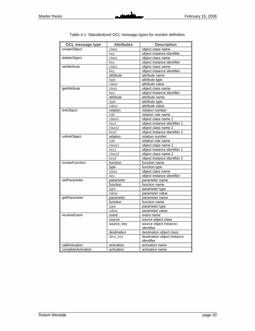
The CODIAG_NAVRAD and PFDFEU_NAVRAD modules are diagnostic components specifically designed for interpreting the subsystem messages. The PFD software component collects and processes all diagnostic data from all diagnostic components in the CMS. The processed diagnostic information is presented to the maintainer through a user-interface, which is called Matrix. For the software system maintainer on board a Dutch naval vessel equipped with Guardion CMS, the Matrix is the main diagnostic software tool. In order to obtain the ReqMon OCL definitions, the KAOS approach was used to create the necessary goal structures. To create the goals and goal graph, existing requirement documentation and available technical documentation can be used. For instance, for the CODIAG _NAVRAD module, the requirement documentation consists of a requirement document written by the design team [2] and a component description document written by the developers [8]. A partial goal graph for the navigation radar system was already presented in Figure 4.3. Based on the informal OCL statements from the goal structures, the monitor specifications are defined. As was mentioned in Section 2.6, ReqMon assumes dynamic traceability between software objects and requirements. This means that the software should be instrumented to sent programming events to the ReqMon daemons. In case of the CMS software, the standard debugging output can be used. The instrumentation for producing this output is added by the in-house developed compiler. The produced debug output can provide programming information down to the attribute-level, thus satisfying the dynamic traceability requirement. Because the CMS debug output differs from the ReqMon OCL messages approach, the need for mapping actual debug messages to OCL custom message types. Therefore, the set of possible OCL message types that may be generated by the CMS components has been standardized. These are the message types that are used in the OCL monitor definitions. An overview is given in Table 4.1. After definition, the monitors can be compiled to JESS code using the ReqMon compiler. To verify the monitors, JESS scenarios are used. These scenarios simulate the event stream from the CMS software components. The event streams are based on the debug logging output for the components. The prototype assumes that the standard debugging instrumentation has been suited to send program events that are compatible with ReqMon. JESS code has been created for the goals of CODIAG_NAVRAD, PFDFEU_NAVRAD and PFD. The scenarios are constructed from jassert statements, which are ReqMon extensions to the standard assert function for defining facts in JESS. Using these statements, the programming events for a software component can be simulated, for instance the creation of an relation between two instances of object classes, or the change in value of a function parameter. In other words, the JESS scenarios simulate the CMS debug output and are used to trigger the monitors defined in the OCL definition language. A simple scenario example is the simulation of a software component crash. In this case, the periodic heartbeats of the components that are normally sent and received cease to exist. The resulting output from the ReqMon prototype is depicted in Figure 4.7. It shows that the defined software goals are satisfied until one of the software component crashes. The output is presented for illustrative purpose and has been shortened.
Master thesis February 15, 2008
Robert Westdijk page 20
Table 4.1: Standardized OCL message types for monitor definition.
OCL message type Attributes Description
createObject class object class name key object instance identifier
deleteObject
class object class name key object instance identifier
setAttribute
class object class name key object instance identifier attribute attribute name type attribute type value attribute value
getAttribute
class object class name key object instance identifier attribute attribute name type attribute type value attribute value
linkObject relation relation number role relation role name class1 object class name 1 key1 object instance identifier 1 class2 object class name 2 key2 object instance identifier 2
unlinkObject
relation relation number role relation role name class1 object class name 1 key1 object instance identifier 1 class2 object class name 2 key2 object instance identifier 2
invokeFunction function function name type function type class object class name key object instance identifier
setParameter
parameter parameter name function function name type parameter type value parameter value
getParameter
parameter parameter name function function name type parameter type value parameter value
receiveEvent
event event name source source object class source_key source object instance
identifier destination destination object class dest_key destination object instance
identifier callActivation activation activation name completeActivation activation activation name

Master thesis February 15, 2008
Robert Westdijk page 21
INFO ReqMon: 90:[_global] ScopeActivation@1fe571f : Scope Global (global) became active. 14:42:48 INFO Internal: System is ready. 14:42:51 INFO Internal: Running file ‘scenario1.cl p’... 14:42:51 INFO Internal: Setting the focus to the R T Jess module. 14:42:51 INFO Internal: Running JESS... 14:42:51 INFO Internal: Running scenario. Simulati ng event stream... 14:42:51 INFO Internal: Execute ReqMon thread 14:42:51 INFO ReqMon: 101:[default] Peval@1f78b68: Property IS_Existence[ScopeActivation@1fe571f; ProgramEvent@ 1843a75] is TRUE. 14:42:52 INFO ReqMon: 126:[default] Peval@1f03691: Property RSM_Sequence[ScopeActivation@1fe571f; ProgramEvent@ d3c65d ProgramEvent@10e35d5] is TRUE. ~ 14:42:52 INFO Internal: Goal ‘Achieve[InterfaceSta tusKnown]’ is satisfied. 14:42:52 INFO Internal: Goal ‘Maintain[SubsystemHe artbeatPresent]’ is satisfied. 14:42:53 INFO Internal: Simulating periodic activa tions 14:42:53 INFO Internal: Execute ReqMon thread ~ 14:43:03 ERROR ReqMon: 268:[default] Peval@28305d: Property CSO_Sequence[ScopeActivation@1fe571f; ProgramEvent@ 2798e7] is FALSE. 14:43:05 ERROR ReqMon: 278:[default] Peval@3afb99: Property HBDC_CDNR_Sequence[ScopeActivation@1fe571f; Program Event@1a0d866] is FALSE. 14:43:05 ERROR ReqMon: 287:[default] Peval@19fe451 : Property HBDC_Chain_Seq[ScopeActivation@1fe571f; ProgramEven t@1a0d866] is FALSE. 14:43:05 INFO Internal: GOAL ‘Maintain[DiagnosticH eartbeatReceived]’ is NOT SATISFIED!! 14:43:05 INFO Internal: A diagnostic heartbeat fro m a diagnostic chain is not received any longer. 14:43:06 INFO Internal: Execute ReqMon thread 14:43:07 INFO Internal: End of simulation
Figure 4.7: An example of ReqMon output.
4.2.2 Reasoner prototype To demonstrate the uses of requirements monitoring, a second prototype has been developed. For this prototype, the CMS Goalkeeper software is used. The Goalkeeper is the Close-In Weapon System (CIWS) found onboard Dutch naval vessels. It forms the last line of defense against incoming missiles. It consists of a Gatling gun, a search radar and a tracking radar. The system is designed to work fully autonomous. The Goalkeeper system is a more operational example of a CMS software chain. Various software modules are needed for remote control of the Goalkeeper from the Command Centre, which are the COGK, CECIWS modules and D2000 user interface. For analyses of the diagnostic messages from the system, the modules CODIAG_GK, PFDFEU_GK and PFD exist. The diagnostic information is presented via the MATRIX maintainer user interface in the Command Centre. Figure 4.8 depicts the software coordination model for this software chain.
Figure 4.8: Software coordination model for the CMS Goalkeeper software chain.
Master thesis February 15, 2008
Robert Westdijk page 22
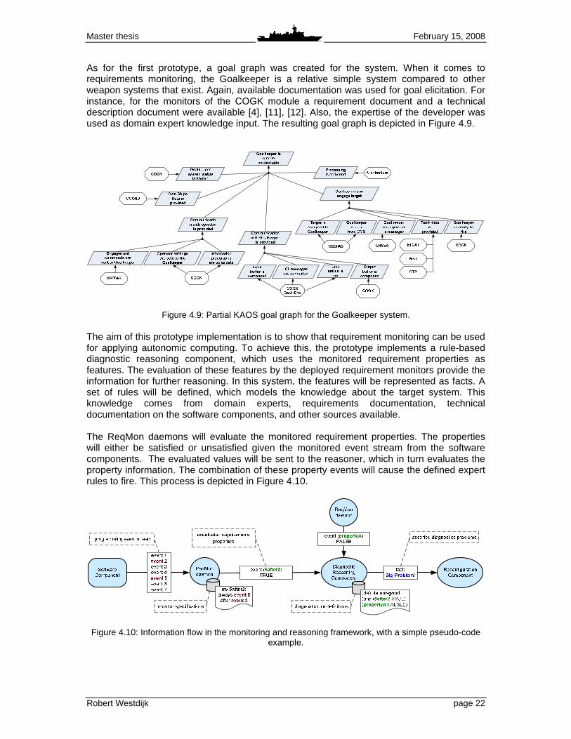
As for the first prototype, a goal graph was created for the system. When it comes to requirements monitoring, the Goalkeeper is a relative simple system compared to other weapon systems that exist. Again, available documentation was used for goal elicitation. For instance, for the monitors of the COGK module a requirement document and a technical description document were available [4], [11], [12]. Also, the expertise of the developer was used as domain expert knowledge input. The resulting goal graph is depicted in Figure 4.9.
Figure 4.9: Partial KAOS goal graph for the Goalkeeper system. The aim of this prototype implementation is to show that requirement monitoring can be used for applying autonomic computing. To achieve this, the prototype implements a rule-based diagnostic reasoning component, which uses the monitored requirement properties as features. The evaluation of these features by the deployed requirement monitors provide the information for further reasoning. In this system, the features will be represented as facts. A set of rules will be defined, which models the knowledge about the target system. This knowledge comes from domain experts, requirements documentation, technical documentation on the software components, and other sources available. The ReqMon daemons will evaluate the monitored requirement properties. The properties will either be satisfied or unsatisfied given the monitored event stream from the software components. The evaluated values will be sent to the reasoner, which in turn evaluates the property information. The combination of these property events will cause the defined expert rules to fire. This process is depicted in Figure 4.10.
Figure 4.10: Information flow in the monitoring and reasoning framework, with a simple pseudo-code
example.
Master thesis February 15, 2008
Robert Westdijk page 23
To demonstrate how the diagnostic rules can be constructed, an elaborate example is given. Consider the following goal structure for the goal “Goalkeeper status is known”, which defines five properties that should be monitored: SystemGoal Goalkeeper status is known
InformalDef The general system status should be known
GoalPattern Achieve Concerns System_Monitor, GK_System OclInformalDef 1
If the Goalkeeper status is known, an instance of System_Monitor should be monitoring it
OclInformalDef 2 If the System_Monitor is activated, the control_mod e and operating_mode cannot be invalid
OclInformalDef 3 When the Goalkeeper had control, the CMS cannot hav e control and vice versa
OclInformalDef 4 The fire_status of Goalkeeper can either be ready_t o_fire or standby
OclInformalDef 5 When the simulation mode of Goalkeeper is started , the
System_Monitor should report this . In the example, OclInformalDef1 states that when the status of the Goalkeeper is known, the System_Monitor should be monitoring it. Note that System_Monitor refers to an UML class in the software model COGK. The name of this object has been changed for reasons of confidentiality. In all examples hereafter that contain information related to the UML models of CMS modules, the names have been altered. However, the examples still reflect the actual implementation of these components. For OclInformalDef1, the System_Monitor is activated by the creation of relation R15 between that object and GK_System, which is an object representing the Goalkeeper system. The creation of this link should be monitored, which results in the following monitor specification: def : linkMonGK: Sequence( OclMessage ) = receivedMessages (linkObject()) -> select ( m | m.relation = 'R15' and m.cla ss1 = 'GK_System' and
m.class2 = 'System_Monitor')
inv : eventuallyLMonGK: eventually linkMonGK . The OclInformalDef2 from the goal structure example states that if the System_Monitor is activated, the control_mode and operating_mode of the Goalkeeper cannot be invalid. The monitor definitions for this requirement look like: def : callInit: Sequence( OclMessage ) = receivedMessages (callActivation() -> select( m | m.activation = 'Initialize') def : setOpMode_Inv: Sequence( OclMessage ) = receivedMessages (setAttribute())
-> select( m | m.class = 'System_Monitor' and m.att ribute = 'operating_mode' and m.value = 'inva lid' )

Master thesis February 15, 2008
Robert Westdijk page 24
def : setConMode_Inv: Sequence( OclMessage )= receivedMessages (setAttribute()) -> select( m | m.class = 'System_Monitor' and m.attribute = 'control_mode' and m.value = ' invalid') inv : OpMode_after_Init: after (callInit) never setOpMode_Inv
inv : ConMode_after_Init: after (callInit) never setConMode_Inv . Now, suppose that after relation R15 has been created, an invalid value for the control_mode or operating_mode of the Goalkeeper indicates the manifestation of some known problem in the system. For all of these properties, an OCL monitor definition has been created. However, combining these properties requires a JESS rule definition: (defrule GK-known-problem-detected (and (or (monitor-event (property OpMode_after_In it)(evaluated FALSE)) (monitor-event (property ConMode_after_I nit)(evaluated FALSE))) (monitor-event (property eventuallyLMonGK)(e valuated TRUE))) =>
(assert (Goalkeeper-known-problem-has-been-detect ed))) . In this case, the defined rule only uses information from a single ReqMon daemon which is instantiated to monitor the COGK module. As was shown in Figure 4.10, the reasoner can receive property evaluations from multiple instances of the ReqMon daemon. This allows detection of diagnostic problem throughout the software system. In the Section 5, more reasoning examples will be presented.
4.2.3 Prototype development environment The ReqMon requirements monitoring framework forms the core of the development and test environment. It is based on the JESS Java Expert System Shell programming language for creating AI expert systems. Beside the standard JESS command line, it also offers a plug-in for the Java-based Eclipse IDE. However, for prototype development, the command line-based ReqMon version is used. This is because the Eclipse plug-in was not available at the time of the implementation of the first requirements monitoring prototype. Moreover, the updates that are released periodically always feature the command line-based ReqMon version first. Updates for the Eclipse IDE version follow later on. During the thesis project, the developer of ReqMon, Dr. Robinson, was regularly consulted. To accommodate JESS and ReqMon, the Cygwin environment was used. Cygwin is a Linux-like environment, which enables the use of GNU development tools on Microsoft Windows. It can be downloaded freely [5]. Various shell scripts have been created to simplify standard actions, such as starting JESS and ReqMon, compiling ReqMon OCL monitor definitions and file management. A screenshot of the development environment is depicted in Figure 4.11. For the definition of scripts, ReqMon monitors, and JESS rules, the XEmacs customizable text editor [40] has been enhanced with shell script, OCL and JESS highlighting. To verify the correct functionality of the ReqMon framework, test monitor definitions have been created. Two types of tests are applied here, which are tests for the OCL message types and for the OCL invariants. During the course of this thesis project, various shortcomings and bugs in the framework and the OCL compiler were detected. These have been reported by the author to Dr. Robinson. All of the bugs reported by the author have been solved in the most recent version of the ReqMon framework and the OCL compiler6. 6 The latest versions used in this thesis project are ReqMon 1.0.35 and OCL compiler 1.0.10.
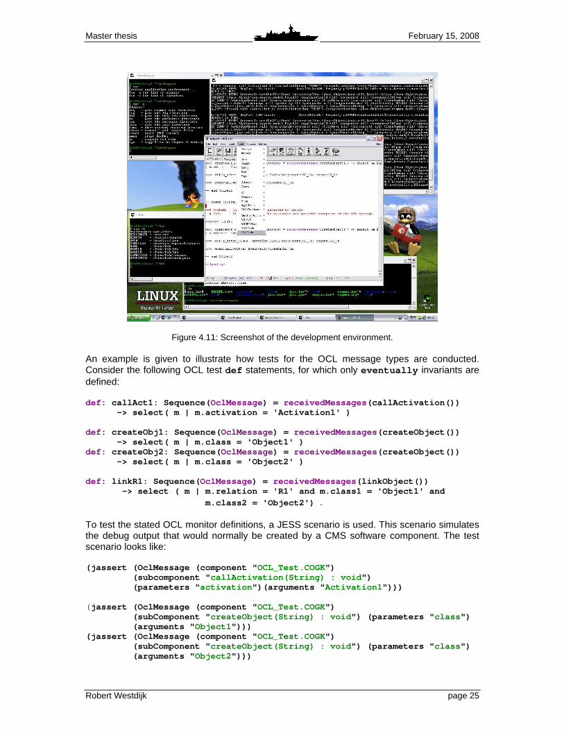
Master thesis February 15, 2008
Robert Westdijk page 25
Figure 4.11: Screenshot of the development environment. An example is given to illustrate how tests for the OCL message types are conducted. Consider the following OCL test def statements, for which only eventually invariants are defined: def : callAct1: Sequence( OclMessage ) = receivedMessages (callActivation()) -> select( m | m.activation = 'Activation1' ) def : createObj1: Sequence( OclMessage ) = receivedMessages (createObject()) -> select( m | m.class = 'Object1' ) def : createObj2: Sequence( OclMessage ) = receivedMessages (createObject()) -> select( m | m.class = 'Object2' ) def : linkR1: Sequence( OclMessage ) = receivedMessages (linkObject()) -> select ( m | m.relation = 'R1' and m.clas s1 = 'Object1' and
m.class2 = 'Object2') . To test the stated OCL monitor definitions, a JESS scenario is used. This scenario simulates the debug output that would normally be created by a CMS software component. The test scenario looks like: (jassert (OclMessage (component " OCL_Test.COGK") (subcomponent " callActivation(String) : void ") (parameters " activation ")(arguments " Activation1 "))) ( jassert (OclMessage (component " OCL_Test.COGK") (subComponent " createObject(String) : void ") (parameters " class ") (arguments " Object1 "))) (jassert (OclMessage (component " OCL_Test.COGK") (subComponent " createObject(String) : void ") (parameters " class ") (arguments " Object2 ")))

Master thesis February 15, 2008
Robert Westdijk page 26
(jassert (OclMessage (component " OCL_Test.COGK") (subComponent " linkObject(String) : void ") (parameters " relation " " class1 " " class2 ")
(arguments " R1" " Object1 " " Object2 "))) . In the example scenario showed above, added log info, run commands and comment have been left out for clarity. The resulting ReqMon output is depicted in Figure 4.12, in which the debug information has been omitted. By running the test scenario, it can be checked whether the applied OCL message type actually work. In this case, the use of callActivation , createObject and linkObject is demonstrated.
15:38:56 INFO Internal: Activation1 has been calle d 15:38:56 INFO ReqMon: 9:org.reqmon.model.ScopeAc tivation@12f1bf0 15:38:57 INFO ReqMon: 19:[null] Peval@ 3e97df: Property p@COGK[eventuallyAct1,eventually_1][ScopeActivation @12f1bf0; ContextVariable@120540c] is TRUE. 15:38:57 INFO Internal: Object 1 has been created 15:38:57 INFO ReqMon: 27:[null] Peval@1 0c0f66: Property p@COGK[eventuallyObj1,eventually_1][ScopeActivation @12f1bf0; ContextVariable@878c4c] is TRUE. 15:38:57 INFO Internal: Object 2 has been created 15:38:57 INFO ReqMon: 29:[null] Peval@ e265d0: Property p@COGK[eventuallyObj2,eventually_1][ScopeActivation @12f1bf0; ContextVariable@878c4c] is TRUE. 15:38:57 INFO Internal: Link R1 is created 15:38:57 INFO ReqMon: 36:[null] Peval@1 c1f5b2: Property p@COGK[eventuallyLMonGK,eventually_1][ScopeActivati on@12f1bf0; ContextVariable@14e45b3] is TRUE. 15:38:58 INFO Internal: End of scenario
Figure 4.12: Resulting output for a OCL message type test scenario.
4.2.4 Knowledge elicitation process For the creation of the goal graphs as have been presented in previous sections, various available information sources haven been used. Documentation such as requirements specifications, software component descriptions and development reports offer information on the design and implementation of the software modules. Besides the use of documentation, the knowledge of domain experts also offers a lot of information. Expert knowledge has been especially useful for the creation of suitable case scenarios. To develop the first requirements monitoring prototype, which was based on the CMS Navigation Radar diagnostic software chain as presented in Section 4.2.1, the available technical documentation was the main information source. Since the author was part of the diagnostic software development team for some time, domain expert knowledge was available. For the creation of test scenarios, actual CMS debug output from historic software development testing has been used7. While searching for a suitable software chain candidate for the requirements monitoring prototype, several software developers at CAMS/Force Vision have been interviewed about their software domain. Furthermore, the requirement sources and related available documentation on various domains have been examined. Based on the interviews and the studied requirements, it was concluded that there are no solid guidelines for requirement specification and software documentations, which have led to a diversity of document styles.
7 This debug output is classified and cannot be presented in this thesis.

Master thesis February 15, 2008
Robert Westdijk page 27
Recently, the requirements extraction process has gained renewed interest at CAMS/Force Vision. Efforts are being made to create guidelines on both style and contents of requirements specification documents. Members of the Goalkeeper software development team have played a role in this process by testing and providing feedback on the proposed guidelines. After conduction various interviews, it became clear that the Goalkeeper software chain also offered some good use cases for prototype testing. Using the documentation and domain knowledge, various goal graphs for the Goalkeeper system were created. Bases on these goal definitions, monitor specifications were created and tested in the prototype development environment. A complete overview of the defined goal structures can be found in [39]. For proof of concept of the proposed diagnostic reasoner, a set of example cases for the Goalkeeper software chain were drawn up. During the development and testing of these cases, the domain expert were regularly consulted. The research of existing requirements documentation and interviews with developers have shown that the implementation of a rigid formalization such as applied by the KAOS approach is very difficult. This thesis proposes an approach to goal structure specification that is less strict, as has been explained in Section 4.1.2. Also, the ReqMon OCL language for formalization is less rigid than that of KAOS. It must be stressed that the aim of this thesis project has not been to implement a new requirements engineering process for software development, but rather to use an existing one as a basis for requirements monitoring implementation.

Master thesis February 15, 2008
Robert Westdijk page 28

Master thesis February 15, 2008
Robert Westdijk page 29
5 Results In this chapter, the results of simulations with the prototypes are presented. Section 5.1. gives an overview of the case examples that will be given. Section 5.2 discusses a case that shows how the monitoring framework can support the developer. A demonstration for the assistance for software users and maintainers is discussed in Sections 5.3 and 5.4. Finally, Section 5.5 explains how the autonomic computing loop should be closed.
5.1 Overview of results Two prototypes were presented in the previous chapter. They were built to verify the feasibility of incorporating requirements monitoring in the CMS and to demonstrate that it can be used for implementing autonomic computing. The first prototype acts as a proof of concept. Monitor definitions have been created and tested for the navigation radars diagnostic software chain. They demonstrate the feasibility of using the KAOS approach to requirements engineering and the ReqMon monitoring framework for CMS software modules. Based on this prototype, a second prototype has been developed. This prototype incorporates a diagnostic reasoner to show that the diagnostic information acquired by requirements monitoring can be used for autonomic computing. Section 3.2 identified three other uses for requirements monitoring: 1. Requirements monitoring during software development and testing can provide useful
information for the developer. 2. The run-time goal information can be redirected to the operator to provide feedback
about system performance and errors. 3. The collected goal information can be used by an AI system to make a first diagnosis for
the software maintenance technicians on board in case of system malfunctions. For both prototypes several monitor definitions and test scenarios have been designed. To illustrate how the requirements monitoring framework and the diagnostic reasoning component operate, four example cases are presented. Three cases represents the uses for requirements monitoring as stated above, while a fourth demonstrates the application of autonomic computing. All examples are based on the Goalkeeper software chain as was presented in Section 4.2.2.
5.2 Case 1: Supporting the developer During CMS software development, incremental tests are carried out. The white and black box tests for a single component can be carried out locally in the development environment. Integration tests can be done on the so-called Target system at CAMS/Force Vision, on which the Guardion CMS software is installed. It resembles the Command Centre as found aboard Dutch naval vessels. Software acceptance are always carried on the actual CMS on board the ships. When applying requirements monitoring as proposed in this research, the developer is enabled to implement monitoring definitions in the software based on the specified requirements. For testing a single software component, these definitions can provide useful debugging information. For instance, the goal “Received diagnostic data is converted to information” is operationalized by the CODIAG_GK software module. One of the informal OCL definitions

Master thesis February 15, 2008
Robert Westdijk page 30
for this goals reads: “In response to a received Message, a Condition should be sent”, where Message and Condition both refer to an object class. The corresponding formal OCL specification looks like: def : createMsg: Sequence( OclMessage ) = receivedMessages (createObject()) -> select( m | m.class = 'Message' ) def : createCond: Sequence( OclMessage ) = receivedMessages (createObject()) -> select( m | m.class = 'Condition' )
inv : Cond_response_Msg: response @0d:0h:0m:10s(createCond, createMsg) . The PFDFEU_GK is the database component, which holds information about possible diagnostic messages that can be received via the CODIAG_GK from the Goalkeeper system. The requirement documentation for both components specify which messages should be contained in the database. Using the previous monitor, the developer can easily check whether the creation of a Message is followed by the creation of a Condition, thus satisfying the stated requirement. Using the same approach, it can be checked whether this software component satisfies all goals that it should operationalize. By combing this monitor and requirements monitors from other software components, higher-level monitoring is also possible. The presented the Cond_response_Msg property monitors the mapping of the incoming diagnostic messages directly from the Goalkeeper system. The PFDFEU_GK software module receives these generic messages and maps them as a condition on a certain Goalkeeper technical component, represented by an object class. This can also be monitored. Using these OCL monitor definitions, a rule can be created that checks whether the complete message set is presented in the message database: (defrule message-not-in-database " Message is not in the diagnostic database " (and (or (monitor-event (property Msg_response_F1 _True)(evaluated TRUE)) (monitor-event (property Msg_response_F1 _False)(evaluated TRUE)) (monitor-event (property Msg_response_F2 _True)(evaluated TRUE)) (monitor-event (property Msg_response_F2 _False)
(evaluated TRUE))) (monitor-event (property Cond_response_Msg)( evaluated FALSE)) (monitor-event (property PHB_PFDGK_after_PFD GK)(evaluated TRUE))) =>
(assert (raise-alert d1))) . In this definition, an extra check is added by incorporating the PHB_PFDGK_after_PFDGK property. This property will remain satisfied as long as heartbeat objects are sent from CODIAG_GK to PFDFEU_GK. The assertion of d1 in the rule definition indicates which database entry in the JESS simulation environment should be raised. The monitoring of the PHB_PFDGK_after_PFDGK property ensures that when the rule is fired, the developer does not have to check whether this is because of a failure in the communication between the two software modules. Thus, when there is no condition mapping despite the creation of a diagnostic message by the Goalkeeper system, this will mean that the message is not in the database and should be added. When this monitor scheme would be deployed in the real CMS environment, it could even detect diagnostic messages being sent that were not foreseen by the requirement designer, for instance because the available interface documentation was incomplete.

Master thesis February 15, 2008
Robert Westdijk page 31
5.3 Case 2: Informing the operator Using the requirements monitors and the diagnostic reasoner, the operator can be informed about the status of the system. When requirements are not met, the monitors can raise operator alerts. Here, an example of this use of requirements monitoring is given for the Goalkeeper software chain. In order for the Goalkeeper to be able to engage targets, it should eventually become in a ready-to-fire state. This means, that all firing preconditions have been satisfied. Most preconditions are hardware-related, for instance fire inhibit switches that should be switched in the right position or safing pins that should be removed. However, some preconditions must be satisfied by the COGK software module. When the fire command is given by the operator using the CMS Goalkeeper user interface, three software conditions should be satisfied: the controle_mode should be set to the CMS, the operating_mode should be set to manual and the Goalkeeper should report ready-to-fire. The latter condition is achieved by removing all necessary hardware constraints, while the first two should be set by the operator. By defining a monitor for all three pre-firing software properties, the operator can be warned when a fire command is given while the Goalkeeper is not able to comply. Using the precedence expression, the setting of the control_mode , operating_mode and fire_mode are monitored as a sequence. Before the fire command can be given, all elements of this sequence should have been received. The System_Monitor class ensures that the Goalkeeper system status is known. The corresponding monitor definition would look like: def : setSysMode_RtF: Sequence( OclMessage )= receivedMessages (setAttribute()) -> select( m | m.class = 'System_Monitor' and m.attribute = 'fire_mode' and m.value = 'ready_t o_fire' ) def : setConMode_CMS: Sequence( OclMessage )= receivedMessages (setAttribute()) -> select( m | m.class = 'System_Monitor' and m.attribute = 'control_mode' and m.value = 'CMS' ) def : setOpMode_Man: Sequence( OclMessage ) = receivedMessages (setAttribute()) -> select( m | m.class = 'System_Monitor' and m.attribute = 'operating_mode' and m.value = 'ma nual' ) def : setFireCmd_Fire: Sequence( OclMessage )= receivedMessages (setAttribute()) -> select( m | m.class = 'Fire_Command' and m .attribute = 'fire_request' and m.value = ' start' ) inv : before setFireCmd_Fire always
precedence (setConMode_Man,setConMode_CMS,setSysMode_RtF) . The incorporation of the diagnostic reasoner provides an alternative way for monitoring the firing preconditions. In the requirement monitor definition, the software conditions and the fire command can be monitored simply by using the eventually expression, which becomes true when the defined OCL message is received. The composite requirement for the preconditions can now be monitored using the JESS rule definitions. By creating multiple rule definitions, the operator can be informed about the exact cause of the incompliance of the system. This could be accomplished by a simple pop-up in the user interface, for instance as depicted in Figure 5.1.

Master thesis February 15, 2008
Robert Westdijk page 32
Figure 5.1: Example of a possible error pop-up for a Goalkeeper operator.8 The rule variant that would lead to the message as depicted in Figure 5.1 would look like: (defrule goalkeeper-not-ready-to-fire " Goalkeeper is not ready to fire " (and (monitor-event (property eventuallyFireCmd)( evaluated TRUE)) (monitor-event (property eventuallyConCMS)(e valuated TRUE)) (monitor-event (property eventuallyOpMan)(ev aluated TRUE)) (monitor-event (property eventuallyModeRtf)( evaluated FALSE))) =>
(assert (raise-alert c3))) . The c3 alert entry is defined as: (alert (id c3)(module " COGK")(error " Goalkeeper is not ready to fire ") (cause " Goalkeeper does not report ready-to-fire ")
(solution " Confirm that all GK safety features have been remov ed")) . As a second example, the output of a JESS simulation for another rule variant is given in Figure 5.2. In this case, the Goalkeeper system reports ready-to-fire and is controlled by CMS. However, the operator has neglected to switch to manual operation. When the fire command is given, the diagnostic reasoner issues a warring that will be displayed through the user interface. The problem can then be corrected accordingly.
8 For reasons of confidentiality, an old (obsolete) user interface design is depicted here.

Master thesis February 15, 2008
Robert Westdijk page 33
Figure 5.2: Example output from a JESS simulation.
5.4 Case 3: Assisting the maintainer Besides the use of the diagnostic reasoning component for informing the software user, the information from this component can also be utilized for maintainer assistance. The system can issue alerts when requirements are not met, but can also provide additional diagnostic information. This can help the maintainer with the formulation of a fault hypothesis. It is also possible to let the system check certain hypothesis automatically. To illustrate this, an example is given. The Goalkeeper system is designed to operate autonomously . This means that it has its own suite of sensors to detect and track possible threats. An automatic surveillance sector can be defined, but it is also possible to cue hostile tracks other sensors. To keep tracking its targets, the Goalkeeper must be aware of the heading of the ship. The heading is one of the attribute values of the Own_Ship_Data object class, which can be found throughout the CMS software. This information is supplied by a hardware sources, which interface with the CMS via the COOSD software module. Thus, the goal “Own Ship Data is provided” is operationalized by the COOSD module. To check if the COGK and CECIWS components receive the data, monitors check the creation of the input object, which is a direct mapping of Own_Ship_Data instances on the output of COOSD. To ensure that the COOSD module is still running, the process heartbeat object is also monitored. If the process heartbeat is created while the input objects are not, there is a problem. The corresponding rule definition is stated as follows: (defrule no-own-ship-data " Goalkeeper does not receive Own Ship data " (and (monitor-event (property OSDCo_after_OSDCo)( evaluated FALSE)) (monitor-event (property OSDCe_after_OSDCe)( evaluated FALSE)) (monitor-event (property PHB_COSD_after_PHB_ COSD)(evaluated FALSE))) =>
(assert (raise-alert c12))) . Using the ReqMon monitors and the rule definition stated above, the operator could be warned that the Goalkeeper system is not receiving any heading information. However, what would really be desirable, is for the CMS system itself to react to this error. If the COOSD process is running, but no instances of Own_Ship_Data are received by COGK and CECIWS, then the root cause of the problem will properly be software-related or infrastructural. The diagnostic information retrieved by the system’s actions will increase the knowledge of the problem for the maintainers onboard, hence decreasing the number of fault hypotheses for them to check.
Jess> INFO: Property eventuallyOpMan is evaluated F ALSE INFO: Property eventuallyConCMS is evaluated TRUE INFO: Property eventuallyModeRtf is evaluated TRUE INFO: Property eventuallyFireCmd is evaluated TRUE ALERT: Error in module COGK ALERT: Description: Goalkeeper is not ready to fire ALERT: Cause: Goalkeeper is not in mode Manual ALERT: Solution: Select Goalkeeper Manual mode ~ Jess> INFO: Property eventuallyOpMan is evaluated T RUE NOTICE: Error "Goalkeeper is not ready to fire" is no longer valid
Master thesis February 15, 2008
Robert Westdijk page 34
Since the monitored PHB_COSD_after_PHB_COSD property is evaluated true, it is known that the COOSD module is still running. Suppose that the monitored property HInfo_after_HInfo indicates whether this module receives the heading from the hardware source. A rule could be added that fires when the “no-own-ship-data” alert (c12 ) is raised, which checks the evaluation of this property: (defrule check-heading-information " Check the creation of heading information for Goalk eeper " (and (alert (id c12)(raised TRUE)) (monitor-event (property HInfo_after_HInfo)( evaluated FALSE))) =>
(assert (GK-heading-problem-localized))) . Thus, when this rule is fired, the system will inform the maintainer that there is a possible hardware problem. If this rule is not fired, the maintainer knows that the hardware does not have to be checked. This is just a simple example of using additional diagnostic information from the requirements monitors for fault localization, but more advanced rules can be applied when more knowledge is added.
5.5 Case 4: Closing the loop The use of the ReqMon OCL monitor specifications offers the developer a flexible and scalable approach for monitoring software requirements. With the development of the JESS diagnostic reasoner it is demonstrated that requirements monitoring can also be used as a basis for further diagnostic reasoning. The evaluated goal properties provide knowledge about the overall state of the monitored software. The previous case illustrated this. To close the autonomic computing OODA loop as was discussed in Section 3.3, the system must be able to perform actions in the Act phase that solve the problems detected in the Observe phase. In the context of self-management, this research project focuses on the ability of self-healing. Using requirements monitoring, the system can examine, find and diagnose problems. In general, healing actions will be reconfiguration actions [1], [16], [26], [34]. This can for instance be a simple restart of a software component or the re-instantiating of a module on another host computer. By adding a reconfiguration component, it should be able to react to system malfunctions by carrying out some reconfiguration plan. In the case described previously in Section 5.4, it was demonstrated how fault hypotheses can be formed based on the monitored requirement properties. The system knowledge is enhanced by using information for multiple monitors and adding more advanced diagnostic rules. By adding the ability of performing reconfiguration actions, the system is enable to not only reason about problems, but also to solve them. Recapitulating, the COOSD module is necessary for the goal “Own Ship Data is provided”. The COGK and CECIWS are control components for the Goalkeeper weapon system. These components are dependent on information about the own ship. The MTL is introduced, which is the software process that provides for the relaying of component objects. Suppose that the CMS software chain for Goalkeeper control is configured such that COGK and CECIWS are running on the same node, while COOSD is instantiated on a different node.. Furthermore, assume that the simple reconfiguration component can perform only two actions: restarting and re-instantiating. Based on this information, a simple example of a reconfiguration plan is presented in Figure 5.3.
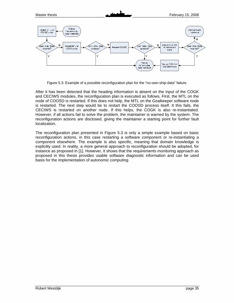
Master thesis February 15, 2008
Robert Westdijk page 35
Figure 5.3: Example of a possible reconfiguration plan for the “no-own-ship-data” failure. After it has been detected that the heading information is absent on the input of the COGK and CECIWS modules, the reconfiguration plan is executed as follows. First, the MTL on the node of COOSD is restarted. If this does not help, the MTL on the Goalkeeper software node is restarted. The next step would be to restart the COOSD process itself. It this fails, the CECIWS is restarted on another node. If this helps, the COGK is also re-instantiated. However, if all actions fail to solve the problem, the maintainer is warned by the system. The reconfiguration actions are disclosed, giving the maintainer a starting point for further fault localization. The reconfiguration plan presented in Figure 5.3 is only a simple example based on basic reconfiguration actions, in this case restarting a software component or re-instantiating a component elsewhere. The example is also specific, meaning that domain knowledge is explicitly used. In reality, a more general approach to reconfiguration should be adopted, for instance as proposed in [1]. However, it shows that the requirements monitoring approach as proposed in this thesis provides usable software diagnostic information and can be used basis for the implementation of autonomic computing.

Master thesis February 15, 2008
Robert Westdijk page 36

Master thesis February 15, 2008
Robert Westdijk page 37
6 Discussion This thesis has presented a model that offers a scalable and flexible approach to implementing requirements monitoring. Simulations with requirement monitoring prototypes have shown that unsatisfied software requirements are detected by the prototype. Software errors that were otherwise discovered by more comprehensive manual fault analysis can be detected automatically by the system. With the creation of the diagnostic reasoning component and by presenting some illustrative case examples, the benefits of using requirements monitoring as a basis for further autonomic development have been made clear. These are mainly the scalability of the approach, the elimination of the need for a comprehensive system model and the relative simple manner in which monitoring and reasoning capabilities can be defined. However, some reflections on the use of the proposed methodology are considered here. Though the KAOS approach to requirements engineering has been around for some time, the ReqMon project is still work in progress. In the course of this research project, several new versions of the monitoring framework have been released. New versions are still being released frequently. The OCL compiler is still under development, but the quality of the compiler is improving with every new version. Furthermore, additional functionality such as a graphical IDE are added incrementally to the ReqMon environment. In other words, the application of this framework in the future looks promising. Based on the creation of requirement monitors for the first prototype, it was concluded that the presented implementation model is scalable for larger systems that the software chain on which is was applied. However, the creation of monitors for the second prototype have proven that sometimes more domain-specific expert knowledge was required then expected. In some cases this may reduce the advantage of limited implementation overhead in the software development phase. Beside the need for domain-specific knowledge in the development phase, system complexity is also an issue. The OCL statements and corresponding rule definitions presented in this work are simple in nature. For a proof of concept, they provide enough complexity to base conclusions on, but when applying the concept to large-scale software systems, their complexity will increase. An increase in complexity will lead to more effort to develop and test the monitor specification and rule definitions. By offering automated tools to the developer, the increase in complexity can be reduced. Also, more elaborate AI techniques than the proposed rule-based approach could be used. Furthermore, the scalability of the ReqMon requirements monitoring framework should be applied here, meaning that important requirements can be monitored more elaborately than less important requirements. ReqMon assumes that there is a dynamic traceability between the software objects and the stated requirements, meaning that the monitors should be able to distinguish between different instances of a defined object class. To satisfy this assumption, the software code should be instrumented to send programming events for monitoring. For the CMS software, the desired instrumentation can be added since the compiler is developed in-house. However, instrumentation could be an issue for other systems. ReqMon offers support for instrumentation only for Java-based programs. For other types of applications, instrumentation should be added by other means. This is considered to be outside the scope of this research.
Master thesis February 15, 2008
Robert Westdijk page 38
In the presented cases, the reconfiguration component was only shortly reviewed. In reality, the issue of dynamic reconfiguration is part of an entire research field with many difficult aspects. More intelligent techniques for reconfiguration planning should be applied, for instance as proposed in [1]. However, the focus in this research is mainly on introducing a novel software monitoring technique and its usage for self-management purposes.
Master thesis February 15, 2008
Robert Westdijk page 39
7 Summary and conclusion This thesis describes a research project which examines the use of requirements monitoring for applying autonomic computing complex software systems. The Guardion Combat Management System (CMS), developed for the Royal Netherlands Navy, is subject to the present study. As a proof of concept, the use of requirements monitoring combined with a rule-based diagnostic reasoner has been proposed. A model has been defined, identifying the transformation steps needed for the implementation of autonomic computing based on requirements monitoring. This model proposes the use of the KAOS goal-orient requirements engineering (RE) approach to define goals for the software components. Monitoring is done using the ReqMon requirements monitoring framework to create software monitor specification. Reasoning capability is added by a JESS rule-based diagnostic reasoner. For testing and simulation of the proposed implementation, two prototypes have been developed. The event stream from the CMS software components can be simulated, as well as the evaluated requirements properties as they are received by the reasoner. The information extracted by applying requirements monitoring to a software system can be used for software testing during software component development. Furthermore, the goal information can provide feedback to the operator during run-time. Last, the properties monitored by the requirements monitoring framework can be used for diagnostic reasoning about the software system. To demonstrate the uses of the proposed monitoring framework, four case examples have been provided for the Goalkeeper Close-In Weapon System (CIWS). The first case features a problem in the Goalkeeper diagnostic software during the development phase. By checking the creation of object instances representing diagnostic messages, the integrity of the diagnostic message database is checked. The second case introduces the preconditions that needs to be satisfied in order for the Goalkeeper to fire. By monitoring the value of object attributes representing these preconditions, the operator is warned when these are not met. The third case focuses on software maintainer support. When heading information is no longer sent to the Goalkeeper software modules, diagnostic expert rules are applied to reduce the set of fault hypotheses. The fourth case deals with autonomizing the software. It shows how the problem of the absence of heading information could be dealt with in an autonomic computing software system. Applying the model has proven that while it is not a trivial task to define the goals of a software component, the overhead introduced in the development phase is limited. Previously documented requirements and software models can be used as sources for the goal extraction process. Preferably, the process of formalizing requirements should be adopted in the requirements engineering phase of software development, although this research has shown that a bottom-up approach is possible. This means that it is possible to implement a monitoring system which monitors the behavior of an already developed software system without the need for a comprehensive system model. The implementation of the model has shown that the ReqMon framework is scalable, both in system size as in the depth of the goal monitoring definitions. This enables the software designer to emphasize important goals in his requirements documents, while it gives the software developer more control over how monitoring definitions are implemented in the software model.

Master thesis February 15, 2008
Robert Westdijk page 40
Based on the research presented in this paper, it is concluded that implementing requirements monitoring an existing combat management system such as the Guardion CMS is feasible. Multiple uses for this approach to software monitoring have been shown, which are the support for the software developer, user and maintainer, as well as the use as a basis for autonomic computing. Requirements monitoring is a promising technique that can be highly beneficial to the human in the loop, considering that the human will stay in the loop in the near future.
Master thesis February 15, 2008
Robert Westdijk page 41
8 Recommendations This research has shown that the use of requirements monitoring has great potential. Not only does it provide a basis for applying autonomic computing, but it is also useful as a monitoring framework for supporting the software developers and users. The extracted goal graphs and the developed prototypes provide an excellent basis for future work. Further research and development based on this thesis would consist of two main issues, which would be the monitoring and reasoning framework itself and the action needed for the self-healing process. In the context of the monitoring and reasoning framework, further examination on the following subjects could be conducted:
1. The issue of instrumenting the CMS software should be addressed. The instrumentation support offered by ReqMon could be used as a starting point.
2. The presented requirements monitors should be deployed in the actual CMS environment, beginning with the Target system at CAMS/Force Vision. Tests should be carried out to see how these monitors perform.
3. Different approaches to the implementation of the diagnostic reasoning component should be considered. The proposed rule-based approach works for smaller applications, but should probably be enhanced when the size of the system implementation increases.
4. The presented work features a very deterministic approach to monitoring and diagnostics. This is sufficient for a proof of concept, but probabilistic aspects such as dealing with incomplete diagnostic information should also be taken into account. The use of AI methods like fuzzy logic or Bayesian reasoning should be researched here.
As for dynamic reconfiguration, further research on the following subjects could be considered:
1. For reasoning within the dynamic reconfiguration component, such as creating reconfiguration plans, the application of more advanced AI techniques should be studied.
2. A reconfiguration component prototype could be developed, which is suited to match the dynamic reconfiguration capabilities as currently implemented in the Guardion CMS.
Master thesis February 15, 2008
Robert Westdijk page 42
Master thesis February 15, 2008
Robert Westdijk page 43
9 References [1] Arshad, N., “A Planning-Based Approach to Failure Recovery in Distributed Systems”,
PhD Thesis, 2006. University of Colorado, Department of Computer Science, 2006. [2] Boudens, H., “Requirements SCC / CODIAG NAVRAD”, CAMS/Force Vision, 07-03-
2005 (internal report). [3] CETIC, Centre of Excellence in Information and Communication Technologies, “An
Overview of the FAUST Toolbox”, http://www.cetic.be/internal220.html. http://www.cetic.be, last visited December 2007.
[4] COGK-team., “COGK allocated DAISY-NT requirements”, CAMS/Force Vision, September 11, 2001 (internal report).
[5] Cygwin website, www.cygwin.com, last visited January 2008. [6] Darimont R, & Lamsweerde, A. van, “Formal Refinement Patterns for Goal-driven
Requirements Elaboration”, Proceedings of the 4th ACM Symposium on the Foundations of Software Engineering, pp.179-190, 1996.
[7] Dingwall-Smith, A., “Run-Time Monitoring of Goal-Oriented Requirements”, PhD Thesis, June 2006. University College London, Department of Computer Science, 2006.
[8] DIR-team, “CODIAG NAVRAD”, CAMS/Force Vision, 06-09-2005 (internal report). [9] Dwyer, M., Avrunin, S. and Corbbet, J., “Patterns in property specifications for finite-
state verification”, Proceedings of the Twenty-First International Conference on Software Engineering, pp. 411-420, 1999.
[10] Fickas, S. & Feather, M., “Requirements monitoring in dynamic systems”, Proceedings of the IEEE International Conference on Requirements Engineering, pp. 140-147, 1995.
[11] Franken, M., “CoGK development v04”, CAMS/Force Vision, June 23, 2005 (internal report, CONFIDENTIAL).
[12] Franken, M., “CoGK outline v01”, CAMS/Force Vision, Augustus 19, 2003 (internal report, CONFIDENTIAL).
[13] Friedman-Hill, E., “JESS in action”, 2003. Manning Publications, Greenwich (USA). [14] Heaven, W. and Finkelstein, A., “A UML profile to support requirements engineering
with KAOS”, IEEE Proceedings - Software, vol. 151, pp. 10-27, 2004. [15] Jess, “About JESS 7”, http://www.jessrules.com/jess/charlemagne.shtml. JESS
website, www.jessrules.com, last visited December 2007. [16] Kephart, J. and Chess, D., “The Vision of Autonomic Computing”, IEEE Computer, pp
41-50, January 2003. [17] Lamsweerde, A. van, “Requirements Engineering in the Year 00: A Research
Perspective”, 2000. Proceedings of the 22nd International Conference on Software Engineering (ICSE’00), pp. 5-19, June 2000.
[18] Lapouchnian, A., “Goal-oriented Requirements Engineering: An Overview of the Current Research”. Depth Report, University of Toronto, 2005.
[19] Lapouchnian, A., Liaskos, S., Mylopoulos, J. & Yu, Y., “Towards Requirement-Driven Autonomic Systems Design”, Design and Evolution of Autonomic Application Software, May 21, 2005.
[20] Letier,E., “Reasoning about Agents in Goal-Oriented Requirements Engineering”, PhD Thesis, May 2001. Université Catholique de Louvain, Dépt. Ingénierie Informatique, 2001.
[21] MCCann, J. and Huebscher, M., “Evaluation issues in Autonomic Computing”, 2004. International Workshop on Agents and Autonomic Computing and Grid Enabled Virtual Organizations (AAC-GEVO’04) at the 3rd International Conference on Grid and Cooperative Computing, pp. 597-608, 2004.
[22] Murch, R., “Autonomic Computing”, 2004. IBM Press/Prentice Hall, New Jersey.
Master thesis February 15, 2008
Robert Westdijk page 44
[23] Nuseibeh, B. and Easterbrook, S., “Requirements Engineering: A Roadmap”, International Conference on Software Engineering, pp. 35-46, June 4-11, 2000.
[24] Objectiver, “A KAOS Tutorial”, September 5, 2003. http://www.objectiver.com/ download/documents/KaosTutorial.pdf. Objectiver website, http://www.objectiver.com, last visited December 2007.
[25] OMG, Object Management Group, “UML 2.0 OCL Specification”, http://www.omg.org/docs/ptc/03-10-14.pdf. OMG website, http://www.omg.org, last visited December 2007.
[26] Oreizy, P., “An Architecture-Based Approach to Self-Adaptive Software”, IEEE Intelligent Systems, pp. 54-62, May/June 1999.
[27] RNLN, “Staff Requirements for the Air Defence and Command Frigate (LCF)”, Royal Netherlands Navy, January 1998. (internal report, CONFIDENTIAL).
[28] Robinson W., “About this project”, http://www.wrobinson.cis.gsu.edu/projects/ reqmon/Home/AboutThisProject/tabid/401/Default.aspx. ReqMon website, http://wrobinson.cis.gsu.edu/projects/reqmon, last visited December 2007.
[29] Robinson, W., “Implementing Rule-based Monitors within a Framework for Continuous Requirements Monitoring”, Proceedings of the 38th Hawaii International Conference on Systems Sciences, 2005.
[30] Robinson, W., “Monitoring Software Quality Requirements”, 2007. Georgia State University, Department of Computer Information Systems, 2007.
[31] Robinson, W., “Monitoring Software Requirements using Instrumented Code”, Proceedings of the 35th Hawaii International Conference on System Sciences, January 7-10, 2002.
[32] Flake, S., “Enhancing the Message Concept of the Object Constraint Language”, Proceedings of the Sixteenth International Conference on Software Engineering and Knowledge Engineering (SEKE’04), pp. 161-166, June 20-24, 2004.
[33] Flake, S., “Towards the Completion of the Formal Semantics of OCL 2.0”, 27th Australasian Computer Science Conference (ACSC’04), pp. 73-82, January 2004.
[34] Tosi, D., “Research Perspectives in Self-Healing Systems”, 27-07-04. Department of Information Technology, Systems and Communications, University of Milano-Bicocca, 2004.
[35] Ward, M. and Heineman, G., “A Framework for Visualizing the Behavior of Component-Based Software Systems”, Conference on Object-Oriented Programming, Systems, Languages and Applications, October 14-18, 2001.
[36] Westdijk, R., “Autonomic Computing for the Combat Management System based on Requirements Monitoring”, Literature study, January 28, 2006. Delft University of Technology, Department of Electrical Engineering, Mathematics and Computer Science, 2006.
[37] Westdijk, R., Rothkrantz, L. and Leijen, A.V. van, “Applying requirements monitoring for autonomic computing in a combat management system”, IEEE AUTOTESTCON Systems Readiness Technology Conference, pp. 349-358, September 17-20, 2007.
[38] Westdijk, R., Rothkrantz, L. and Leijen, A.V. van, “A monitoring and reasoning framework for applying autonomic computing in a combat management system”, Technical report, 21 December 2007. Netherlands Defence Academy, Faculty of Military Science, 2007.
[39] Westdijk, R., “Thesis Progress Report”, CAMS/Force Vision, August 8, 2007 (internal report).
[40] XEmacs website, www.xemacs.org, last visited January 2008.

Master thesis February 15, 2008
Robert Westdijk Annex 1 page 45
Annex 1: Research paper The following pages print the paper “Applying Requirements Monitoring for Autonomic Computing in a Combat Management System”. This paper has been presented at the IEEE AUTOTESTCON Systems Readiness Technology Conference in Baltimore, September 18-20, 2007. It received the “Best paper in the Health Management Track” award.

Master thesis February 15, 2008
Robert Westdijk Annex 1 page 46
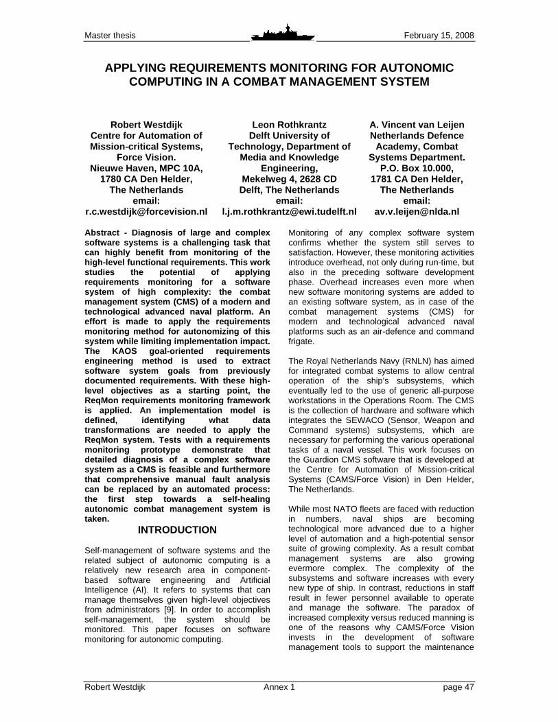
Master thesis February 15, 2008
Robert Westdijk Annex 1 page 47
APPLYING REQUIREMENTS MONITORING FOR AUTONOMIC COMPUTING IN A COMBAT MANAGEMENT SYSTEM
Robert Westdijk Centre for Automation of Mission-critical Systems,
Force Vision. Nieuwe Haven, MPC 10A,
1780 CA Den Helder, The Netherlands
email: [email protected]
Leon Rothkrantz Delft University of
Technology, Department of Media and Knowledge
Engineering, Mekelweg 4, 2628 CD
Delft, The Netherlands email:
A. Vincent van Leijen Netherlands Defence
Academy, Combat Systems Department.
P.O. Box 10.000, 1781 CA Den Helder,
The Netherlands email:
Abstract - Diagnosis of large and complex software systems is a challenging task that can highly benefit from monitoring of the high-level functional requirements. This work studies the potential of applying requirements monitoring for a software system of high complexity: the combat management system (CMS) of a modern and technological advanced naval platform. An effort is made to apply the requirements monitoring method for autonomizing of this system while limiting implementation impact. The KAOS goal-oriented requirements engineering method is used to extract software system goals from previously documented requirements. With these high-level objectives as a starting point, the ReqMon requirements monitoring framework is applied. An implementation model is defined, identifying what data transformations are needed to apply the ReqMon system. Tests with a requirements monitoring prototype demonstrate that detailed diagnosis of a complex software system as a CMS is feasible and furthermore that comprehensive manual fault analysis can be replaced by an automated process: the first step towards a self-healing autonomic combat management system is taken.
INTRODUCTION Self-management of software systems and the related subject of autonomic computing is a relatively new research area in component-based software engineering and Artificial Intelligence (AI). It refers to systems that can manage themselves given high-level objectives from administrators [9]. In order to accomplish self-management, the system should be monitored. This paper focuses on software monitoring for autonomic computing.
Monitoring of any complex software system confirms whether the system still serves to satisfaction. However, these monitoring activities introduce overhead, not only during run-time, but also in the preceding software development phase. Overhead increases even more when new software monitoring systems are added to an existing software system, as in case of the combat management systems (CMS) for modern and technological advanced naval platforms such as an air-defence and command frigate. The Royal Netherlands Navy (RNLN) has aimed for integrated combat systems to allow central operation of the ship’s subsystems, which eventually led to the use of generic all-purpose workstations in the Operations Room. The CMS is the collection of hardware and software which integrates the SEWACO (Sensor, Weapon and Command systems) subsystems, which are necessary for performing the various operational tasks of a naval vessel. This work focuses on the Guardion CMS software that is developed at the Centre for Automation of Mission-critical Systems (CAMS/Force Vision) in Den Helder, The Netherlands. While most NATO fleets are faced with reduction in numbers, naval ships are becoming technological more advanced due to a higher level of automation and a high-potential sensor suite of growing complexity. As a result combat management systems are also growing evermore complex. The complexity of the subsystems and software increases with every new type of ship. In contrast, reductions in staff result in fewer personnel available to operate and manage the software. The paradox of increased complexity versus reduced manning is one of the reasons why CAMS/Force Vision invests in the development of software management tools to support the maintenance
Master thesis February 15, 2008
Robert Westdijk Annex 1 page 48
at sea, which is by no means a trivial activity. Beside the development of software support tools for the system’s maintainers, completely autonomizing the system is also an issue of interest. The focus of this paper is on the application of requirements monitoring for software maintainer support and as a basis for autonomic computing. The main research objectives are:
1. To define a model for implementing requirements monitoring for the combat management system;
2. To develop a requirements monitoring prototype or demonstrator using the model;
3. To link high-level goals with other software diagnostic data.
It is examined what information can be obtained by applying requirements monitoring and how it may be used. This paper presents the design and some first results of a prototype implementation of requirement monitoring prototype implementation based on the ReqMon system. This monitoring framework has been chosen based on the conclusions of a literature study. While much literature concerns the design of a new requirements monitoring framework, the emphasis of this work is more on implementing a requirements monitoring system in an existing software system. In addition, other diagnostic data sources will be incorporated in the monitoring system. The paper is organized as follows. First, some background information is provided about autonomic computing and requirements monitoring. Then the KAOS methodology is shortly reviewed and the ReqMon requirements monitoring framework is introduced. After the presentation of the model for ReqMon implementation, the prototype is discussed as well as the feature database. Finally, conclusions are drawn.
BACKGROUND Autonomic Computing An autonomic software system should be able to modify its own behavior in order to adapt itself and must be able to manage itself, hence the name “self”-systems for systems that have this ability. There are four main aspects of autonomic computing: self-configuration, self-optimization, self-healing and self-protection
[12]. The application of requirements monitoring as presented in this paper is part of self-healing. The processes of self-management can be viewed as a control loop, as is commonly seen in literature (e.g. [1], [9], [15], [19]). The OODA loop can be applied here, which identifies four phases: Observe, Orient, Decide, and Act. System monitoring is in the observation and orientation phase, in which monitoring data is collected, analysed and interpreted. In the decision phase, it may be decided that action is needed. This decision can be made by some intelligent system, which produces a reconfiguration plan. After it is decided if and what action is to be taken, the reconfiguration plan must be executed. As has been stated, an autonomic system must be able to modify its own behavior. In order to accomplish this, the system must have knowledge about what its required behavior is. For many systems the behavior can be described by means of a system model. However, creating a model of a complex system such as the CMS is extremely difficult. It is commonly accepted that software systems have grown too large to statically verify and analyze [20]. Such an endeavor would require disproportionate time and resources in the development process of a system and would be even more difficult to apply on already developed systems. Requirements monitoring Software development processes are generally constrained by time and budget mainly. Incorporating new monitoring techniques or adapting existing ones has a negative influence on both the time and budget of the development process. Therefore it is interesting to see if techniques can be applied that can be incorporated into the existing software development process and require limited additional development resources. Considering the software development process in general, it can be stated that the behavior of a system is specified in the requirements of the system and consequently in its design. The actual implementation of the software is of no concern here, as long as the desired behavioral properties are accomplished. In this context, the term requirements monitoring is introduced, which is defined as the tracking of the run-time behavior of a system and the determination whether that running system is meeting its requirements [7], [17].

Master thesis February 15, 2008
Robert Westdijk Annex 1 page 49
Using the requirements monitoring approach as a basis for autonomizing of the CMS has potential because of the following advantages: 1. It offers the opportunity to model system
behavior on a high level without the creation of a complex behavioral model;
2. The extra workload required by designers and developers is limited;
3. The method may be implemented for the current version of the CMS and is testable;
4. For use on future versions of the CMS, it offers an approach to streamline the requirements elaboration process.
A prerequisite for conducting requirements monitoring is the formalization of those requirements [10], [18]. This is part of the process of Requirements Engineering (RE). RE is concerned with the identification and refinement of goals, the operationalization of the refined goals and the assignment of responsibilities for the resulting requirements [3]. A more elaborate definition is given in [13]: Requirements engineering is the branch of software engineering concerned with the real-world goals for functions of and constraints on software systems. It is also concerned with the relationship of these factors to precise specifications of the software behavior, and their evolution over time and across software families.
Traditional system analysis methods in requirement engineering are inadequate when dealing with complex software systems [11]. The Goal-Oriented Requirements Engineering (GORE) approach attempts to solve these problems. GORE focuses on activities that precede the specification phase in the traditional RE process. It aims for less emphasis on the question how a software system should operate and more on why a system is needed. GORE approaches provide a breakdown of the composite system requirements into operationalizable goals. These goals provide a basis for requirements monitoring, identifying what part of the system is responsible for what goal. The GORE method KAOS (Knowledge Acquisition in Automated Specification) is a frequently used technique in RE processes and requirement monitors development. It is very well documented and various tooling exists that support the various sub process and steps within this GORE method (e.g. [6], [14]). KAOS uses object models, which can be represented using for instance UML (Unified Modelling Languange) [8].
KAOS The KAOS methodology mainly utilizes formal analysis techniques. It combines semantic nets and implements linear-time temporal logic to formalize and express the goals and other objects of the system [11]. Objects in KAOS are things of interest in the system, whose instances can evolve from state to state. Objects can be entities, relationships or events. Operations are input-output relations over these objects. They can define state transitions and are declared by signatures over objects. Operations have pre, post and trigger conditions. Operations on objects are performed by agents. An agent is an object that acts as a processor for operations. Agents are active components that can be humans, devices, software, etc. Agents operate autonomously. One or more agents can achieve a goal. Goals refer to services, which are functional goals, and to quality of service, which are non-functional goals. Goals are refined in hierarchies using “AND” and “OR” relations. Goal refinement ends when an individual agent operationalizes a sub goal. Using the KAOS approach, a goal graph can be made for a complete software system. This graph can be based on the high-level requirements documentation that is available. For example, the high-level goals for an envisioned naval vessel - and consequently the CMS - can be derived from the staff requirements. The KAOS approach is scalable. Instead of a complete system, it can also be applied on parts of a system. For instance, goals for a single software component can be derived from existing software requirements. Since the Guardion CMS is an existing system, the requirements for the system and its software components have already been drawn up. This calls for a bottom up goal definition strategy, which means that the stated software requirements should be used to create formalized goals. New goals may be added if necessary. The extracted goals will be used to form sub goals of higher level goals, keeping in mind the existing operation capabilities and the staff requirements. Since goals and requirements are so closely related, these terms will be used as synonyms in the rest of this paper.

Master thesis February 15, 2008
Robert Westdijk Annex 1 page 50
IMPLEMENTATION ReqMon Several monitoring systems adopt the KAOS approach to defining and formalizing software requirements. For prototype development, the ReqMon monitoring system as presented in [17] and [18] will be used. ReqMon tools aim to provide a programming interface (API) that simplifies temporal event reasoning in real-time (RT) or near real-time (NRT) [16]. It is implemented in JESS (Java Expert System Shell) and recently also in Drools. JESS and Drools are both Java based rule engines. For prototyping, the JESS variant will be used. To use the ReqMon framework, it is assumed that formal definitions have been drawn up about the desired properties of the software system. The KAOS requirement specification techniques can be applied here. Another assumption is that there must be static and dynamic traceability between the software objects and the stated requirements [17]. Static traceability means that a KAOS object can be traced back to its object definition in the programming code. Dynamic traceability means that the monitor should be able to distinguish between different instances of a defined object class. Software systems that have been developed using a modelling technique satisfy the static traceability prequisite for ReqMon. To achieve dynamic traceability, instrumentation of the software is necessary, meaning the software code is enriched to send programming events for monitoring. For development purposes, the CMS software compiler already adds debugging code to the compiled classes, which can be used for generating these events. Because ReqMon is JESS-based, the KAOS goal definitions are specified in JESS code. However, ReqMon offers a compiler for the OCL Object Constraint Language. OCL is a well-known expression language that enables one to describe constraints on object-oriented models and other object modelling artefacts. It is part of the UML framework. The ReqMon OCL variant extends the UML 2.0 OCL specification to
provide the use of linear-time temporal logic needed for the defining the KAOS goals. To perform requirements monitoring, the monitor must view the stream of activities of a software component and interpret their meaning. ReqMon receives monitoring events, which contain information about the component’s processing. As these events arrive, ReqMon will determine if the predefined requirements are satisfied. It will raise an event itself when requirements are not satisfied. Figure 1 illustrates the data streams for a software component and ReqMon. The CMS is both component-based and network-based, so the requirement monitoring processes must also be. Every software component has its own set of goals, which will be checked by a ReqMon thread or daemon that holds the specific requirement information for that particular component. These daemons will be interconnected so that higher-level system goals can be checked.
Figure 1: Data Streams For A Software
Component Monitored By ReqMon. Implementation model Requirements monitoring can be used as a basis for performing autonomic computing. However, the run-time requirement monitoring information may not provide enough information. Additional system information may be required by the autonomic computing system in order to come to the right decisions and consequent actions. On the other hand, the information extracted by requirements monitoring can have more uses then autonomic computing, as can be seen in Figure 2.
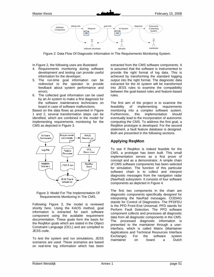
Master thesis February 15, 2008
Robert Westdijk Annex 1 page 51
Software Component
Reqmon AI System
KB KB
debug info goal info diagnose Autonomic Computing
System
software developer operator maintainer
Figure 2: Data Flow Of Diagnostic Information In The Requirements Monitoring System. In Figure 2, the following uses are illustrated: 4. Requirements monitoring during software
development and testing can provide useful information for the developer;
5. The run-time goal information can be redirected to the operator to provide feedback about system performance and errors;
6. The collected goal information can be used by an AI system to make a first diagnosis for the software maintenance technicians on board in case of software malfunctions.
Based on the data flows as presented in Figure 1 and 2, several transformation steps can be identified, which are combined in the model for implementing requirements monitoring for the CMS as depicted in Figure 3.
Figure 3: Model For The Implementation Of Requirements Monitoring In The CMS.
Following Figure 3, the model is reviewed shortly here. Using the KAOS method, goal information is extracted for each software component using the available requirement documentation. These goals form the basis for the ReqMon goals which are stated in the Object Constraint Language (OCL) and are compiled to JESS code. To test the system and run simulations, JESS scenarios are used. These scenarios are based on real-time log information which has been
extracted from the CMS software components. It is assumed that the software is instrumented to provide the right format of log data. This is achieved by transforming the standard logging output into the right format. The diagnostic data extracted for the AI system will be transformed into JESS rules to examine the compatibility between the goal-based rules and feature-based rules. The first aim of the project is to examine the feasibility of implementing requirements monitoring into a complex software system. Furthermore, this implementation should eventually lead to the incorporation of autonomic computing the CMS. To address the first goal, a ReqMon prototype is developed. For the second statement, a fault feature database is designed. Both are presented in the following sections. Applying ReqMon To see if ReqMon is indeed feasible for the CMS, a prototype has been built. This small implementation serves as a first prove of concept and as a demonstrator. A simple chain of CMS software components has been selected for simulation. The function of this particular software chain is to collect and interpret diagnostic messages from the navigation radar (NavRad) subsystem. It consists of four software components as depicted in Figure 4. The first two components in the chain are diagnostic components specifically designed for interpreting the NavRad messages. CODIAG stands for Control of Diagnostics. The PFDFEU is the PFD Front-End Universal. PFD stands for Perform Fault Detection. The PFD software component collects and processes all diagnostic data from all diagnostic components in the CMS. The processed diagnostic information is presented to the maintainer through a user-interface, which is called Matrix (Maintainer Applications and Technical Resources Interface Exchange). For the software system maintainer on board a Dutch

Master thesis February 15, 2008
Robert Westdijk Annex 1 page 52
CODIAG NAVRADControl of Diagnostics
Navigation Radars
Navigation RadarsSubsystem
PFDFEU NAVRADPFD Front End Universal
Navigation Radars
PFDPerform Fault Detection
MATRIXMaintainer Applications
and Technical Resources Interface eXchange
Figure 4: Software Component Chain For Diagnostics Of The Navigation Radar Subsystem.
naval vessel equipped with Guardion CMS, the Matrix is the main diagnostic software tool. To create a ReqMon system the goals for each component should be identified. The goals can be extracted form the existing requirement documentation and the software model that has been created. For the CODIAG NAVRAD example, the requirement documentation consists of a requirement document written by the design team [2] and a component description document written by the developers [5]. As an example, consider the following statement from the requirements “CODIAG NAVRAD shall periodically provide a heartbeat object for testing the diagnostic chain. The period is defined at once every 10 seconds.” The stated requirement will be implemented in the software model and consequent in the compiled programming code. The requirement can be checked by comparing input and output objects during runtime. In this case the requirement can be directly formalized into a goal of this software component. The KAOS methodology offers guidelines for goal elicitation. Examples can be found in various documents and websites, e.g. in [4] and [14]. Creating these goal definitions is a non-trivial task, but the requirements documents and software models can be used as a source. In Figure 5, the goal-graph is depicted for the CODIAG NAVRAD software component. It features the main goals that have been identified.
Figure 5: Goal-graph For The CODIAG
NAVRAD Software Component. The extracted goal must now be implemented in ReqMon. First, the KAOS specification for the
goal is made. For the stated “Provide periodic heartbeat” goal, the goal structure looks like: SystemGoal Maintain[DiagnosticHeartbeatPresent] InformalDef A periodic heartbeat should be sent by the
diagnostic software in order to ascertain it is still running.
Concerns Heartbeat Diagnostic Chain FormalDef �<10 sec Sent(HBDC) .
The specified goal structure serves as a basis for further implementation. It can be added to existing or new requirement documentation in order to formalize the requirements. The formal definition of the goal specification is written in the KAOS temporal logic specification language. For the first version of the prototype, the JESS rule structures have been created manually, since the OCL compiler was not yet available at the time. This manually coded goal comprises of a Sequence property definition, a monitor definition and a timeout definition: ( defproperty HBDC_CDNR_Sequence Sequence ( patterns ( create$ “Heartbeat_Diagnostic_Chain” “Heartbeat_Diagnostic_Chain” )) ( constraints “(RT::ProgramEvent(OBJECT ?event-object) (className ?cn &nth-pattern-matchp ?cn ?n ?patterns)))” ) ( timeouts ( create$ HBDC_Timeout ))) ( defmonitor HBDC_CDNR_Monitor ( property HBDC_CDNR_Sequence )) ( jassert ( RT::Timeout ( name HBDC_Timeout )
( start “+0d:0h:0m:10s” ) ( count 0 ))) . If the ReqMon OCL compiler is used, JESS code is compiled from the OCL specification. In this case, the goal can be specified as: def : Diagnostic_Heartbeat : OclMessage = receivedMessage (Heartbeat_Diagnostic_Chain()) inv : after@0d:0h:0m:10s (Diagnostic_Heartbeat) always Diagnostic_Heartbeat .
JESS code has been created for the goals of CODIAG NAVRAD, PFDFEU and PFD. Using test scenarios, simulation runs can be made. The prototype assumes that the standard debugging instrumentation has been suited to send program events that are compatible with ReqMon. For instance, a component activation followed by the

Master thesis February 15, 2008
Robert Westdijk Annex 1 page 53
INFO ReqMon: 90: [_global] ScopeActivation@1fe571f: Scope Global (gl obal) became active.
14:42:48 INFO Internal: System is ready.
14:42:51 INFO Internal: Running file ‘scenario1.cl p’...
14:42:51 INFO Internal: Setting the focus to the R T Jess module.
14:42:51 INFO Internal: Running JESS...
14:42:51 INFO Internal: Running scenario. Simulati ng event stream...
14:42:51 INFO Internal: Execute ReqMon thread
14:42:51 INFO ReqMon: 101:[default] Peval@1f78b68: Property IS_Existence[ScopeActivation@1fe571f; Pro gramEvent@1843a75] is
TRUE.
14:42:52 INFO ReqMon: 126:[default] Peval@1f03691: Property RSM_Sequence[ScopeActivation@1fe571f; Prog ramEvent@d3c65d
ProgramEvent@10e35d5] is TRUE.
~
14:42:52 INFO Internal: Goal ‘Achieve[InterfaceSta tusKnown]’ is satisfied.
14:42:52 INFO Internal: Goal ‘Maintain[SubsystemHe artbeatPresent]’ is satisfied.
14:42:53 INFO Internal: Simulating periodic activa tions
14:42:53 INFO Internal: Execute ReqMon thread
~
14:43:03 ERROR ReqMon: 268:[default] Peval@28305d: Property CSO_Sequence[ScopeActivation@1fe571f; Pro gramEvent@2798e7] is
FALSE.
14:43:05 ERROR ReqMon: 278:[default] Peval@3afb99: Property HBDC_CDNR_Sequence[ScopeActivation@1fe571 f;
ProgramEvent@1a0d866] is FALSE.
14:43:05 ERROR ReqMon: 287:[default] Peval@19fe451 : Property HBDC_Chain_Seq[ScopeActivation@1fe571f; ProgramEvent@1a0d866]
is FALSE.
14:43:05 INFO Internal: GOAL ‘Maintain[DiagnosticH eartbeatReceived]’ is NOT SATISFIED!!
14:43:05 INFO Internal: A diagnostic heartbeat fro m a diagnostic chain is not received any longer.
14:43:06 INFO Internal: Execute ReqMon thread
14:43:07 INFO Internal: End of simulation
Figure 6: ReqMon Logging Output From The Example Scenario. creation of a heartbeat output object by the CODIAG would be logged in real-time as: 15:08:29.192: External Tracing:
A_CODIAG_NAVRAD_Produce_Heartbeat_activation called .
15:08:29.192: External Tracing:
A_CODIAG_NAVRAD_Produce_Heartbeat_activation unpack ed.
15:08:29.195: External Tracing:
A_CODIAG_NAVRAD_Produce_Heartbeat_activation start event
processing.
15:08:29.195: External Tracing:
A_CODIAG_NAVRAD_Produce_Heartbeat_activation proces sed.
15:08:29.195: Output Signature Data:
O_CODIAG_NAVRAD_Heartbeat_Diagnostic_Chain:
key(28.1.b39cf95b213) ver sion 1.
15:08:29.196: Output Signature Data: get codiag_na me =
CODIAG_ NAVRAD.
15:08:29.196: Output Signature Data: get scc_id = 1.
15:08:29.197: Output Signature Data: get time_vali d =
13-13-2006 15:08:17 :958 .
This actual CMS system logging can be stored in text format and can then be converted into a test scenario, for example: ( jassert ( ProgramEvent
( className CDNR_Produce_Heartbeat” )))
( jassert ( ProgramEvent
( className “Heartbeat_Diagnostic_Chain” )
( parameters “name” )
( parameterTypes “CODIAG_NAVRAD”))) .
A complete test scenario is defined as a series of program events as presented above. An example of a simple test scenario is simulating that a software component crashes. In this case, the periodic heartbeats of the components that are normally sent and received cease to exist. The resulting output from the ReqMon prototype is depicted in Figure 6. It shows that the defined software goals are satisfied until one of the software component crashes. The output is presented for illustrative purpose and has been shortened.
Feature database To further investigate the uses of the information extracted by requirement monitoring, an effort is made to link software goals to other diagnostic system information. In order to do so, diagnostic system data should be collected. This has been achieved by developing a diagnostic database for recording faults within the CMS software. Features of these faults are then extracted and the faults are linked to possible software goals that would not be achieved as a result of these faults. The diagnostic database is a Microsoft Access database application. It is based on an existing diagnostic database, which has been is use by the Test & Integration Team (T&I) at CAMS/Force Vision only recently. This knowledge database is used to store fault data that is collected while integrating and testing the CMS software on board the naval vessels. With this knowledge, recurring faults can be easily solved and fault information is stored for future reference. The T&I database has been adapted to include fault features. Furthermore, additional information can be entered about the impact the fault has on the functionality of the CMS software components. This information can then be related to the software goals of these components. Figure 7 shows a screenshot of the feature database.
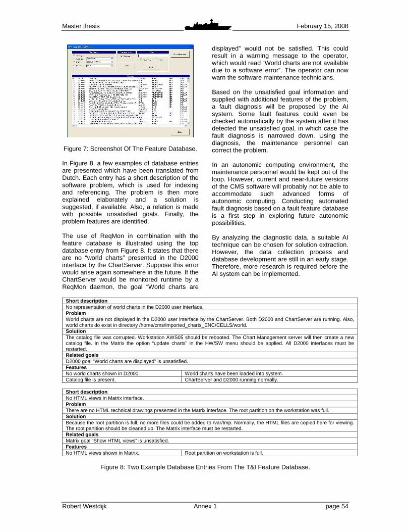
Master thesis February 15, 2008
Robert Westdijk Annex 1 page 54
Figure 7: Screenshot Of The Feature Database. In Figure 8, a few examples of database entries are presented which have been translated from Dutch. Each entry has a short description of the software problem, which is used for indexing and referencing. The problem is then more explained elaborately and a solution is suggested, if available. Also, a relation is made with possible unsatisfied goals. Finally, the problem features are identified. The use of ReqMon in combination with the feature database is illustrated using the top database entry from Figure 8. It states that there are no “world charts” presented in the D2000 interface by the ChartServer. Suppose this error would arise again somewhere in the future. If the ChartServer would be monitored runtime by a ReqMon daemon, the goal “World charts are
displayed” would not be satisfied. This could result in a warning message to the operator, which would read “World charts are not available due to a software error”. The operator can now warn the software maintenance technicians. Based on the unsatisfied goal information and supplied with additional features of the problem, a fault diagnosis will be proposed by the AI system. Some fault features could even be checked automatically by the system after it has detected the unsatisfied goal, in which case the fault diagnosis is narrowed down. Using the diagnosis, the maintenance personnel can correct the problem. In an autonomic computing environment, the maintenance personnel would be kept out of the loop. However, current and near-future versions of the CMS software will probably not be able to accommodate such advanced forms of autonomic computing. Conducting automated fault diagnosis based on a fault feature database is a first step in exploring future autonomic possibilities. By analyzing the diagnostic data, a suitable AI technique can be chosen for solution extraction. However, the data collection process and database development are still in an early stage. Therefore, more research is required before the AI system can be implemented.
Short description No representation of world charts in the D2000 user interface. Problem World charts are not displayed in the D2000 user interface by the ChartServer. Both D2000 and ChartServer are running. Also, world charts do exist in directory /home/cms/imported_charts_ENC/CELLS/world. Solution The catalog file was corrupted. Workstation AWS05 should be rebooted. The Chart Management server will then create a new catalog file. In the Matrix the option “update charts” in the HW/SW menu should be applied. All D2000 interfaces must be restarted. Related goals D2000 goal “World charts are displayed” is unsatisfied. Features No world charts shown in D2000. World charts have been loaded into system. Catalog file is present. ChartServer and D2000 running normally.
Short description No HTML views in Matrix interface. Problem There are no HTML technical drawings presented in the Matrix interface. The root partition on the workstation was full. Solution Because the root partition is full, no more files could be added to /var/tmp. Normally, the HTML files are copied here for viewing. The root partition should be cleaned up. The Matrix interface must be restarted. Related goals Matrix goal “Show HTML views” is unsatisfied. Features No HTML views shown in Matrix. Root partition on workstation is full.
Figure 8: Two Example Database Entries From The T&I Feature Database.

Master thesis February 15, 2008
Robert Westdijk ANNEX 1 page 55
DISCUSSION The research presented in this paper is still work in progress. In order to obtain more tangible results, the ReqMon prototype must be tested on more complicated CMS software components. Also, the feature database should be further developed. More diagnostic data is to be collected and analyzed. The presented model offers a scalable approach to implementing and testing requirements monitoring. When applying the model to a full-scale, some steps may be automated, such as creating test scenarios from a log file. Manual steps such as the creation of goal definitions and subsequent code can be supported by tools, either of-the-shelf, e.g. [14], or developed in-house. Simulations with the prototype have shown that unsatisfied software requirements are detected by the prototype. Software errors that were otherwise only discovered by comprehensive manual fault analysis can be detected automatically by the system. An AI system will combine the information on high-level goals collected by run-time requirements monitoring with the diagnostic data from the feature database. While not all goals may be linked to faults in the database, the database does reveal what effects low-level system faults can have on the high-level behaviour of the software components. Further research will identify which AI techniques can be applied to obtain an automated fault diagnosis using all diagnostic data available.
CONCLUSION This paper describes a research project which examines the use of requirements monitoring in complex software systems. The Guardion Combat Management System (CMS), developed for the Royal Netherlands Navy, is subject to the present study. To implement requirements monitoring using the KAOS method, a model has been defined. Applying this model has proven that while it is not a trivial task to define the goals of a software component, the overhead introduced in development phase is limited. Previously documented requirements and software models can be used as sources for the goal extraction process. This means that it is possible to implement a monitoring system which monitors the behavior of an already
developed software system without the need for a comprehensive system model. A ReqMon prototype was developed for a small software chain to act as a proof of concept. This has shown that the ReqMon framework is scalable, both in system size as in the depth of the goal monitoring definitions. This enables the software designer to emphasize important goals in his requirements documents, while it gives the software developer more control over how monitoring definitions are implemented in the software model. A fault feature database for storing diagnostic information on software errors has been developed. By linking this diagnostic information to the high-level goals, automatic diagnosing of software errors by can be performed by an AI system. This means that it is possible to combine predefined software requirements information with experience diagnostic data, creating a flexible diagnostic framework that can be enhanced when new experience diagnostic data comes available. The implementation of such an AI system is a first step towards autonomic computing for the CMS. Based on the research presented in this paper, it is concluded that implementing requirements monitoring for autonomic computing in an existing combat management system is feasible.
ACKNOWLEDGMENTS The research presented in this paper is sponsored by the Centre for Automation of Mission-critical Systems, Force Vision. I would like to thank William Robinson, the developer of ReqMon, for his support.
REFERENCES [1] Arshad, N. et al, “Automated Dynamic Reconfiguration using AI planning”, Proceedings of the Automated Software Engineering Conference, September 20-25, 2004. [2] Boudens, H., “Requirements SCC/ CODIAG NAVRAD”, Internal document CAMS/Force Vision, 07-03-2005. [3] Darimont R, & Lamsweerde, A. van, “Formal Refinement Patterns for Goal-driven Requirements Elaboration”, Proceedings of the 4th ACM Symposium on the Foundations of Software Engineering, pp.179-190, 1996.

Master thesis February 15, 2008
Robert Westdijk ANNEX 1 page 56
[4] Dardenne, A. et al, “Goal-directed Requirements Acquisition”, Science of Computer Programming, vol 20, pp 3-50, 1993. [5] DIR-team, “CODIAG NAVRAD”, Internal document CAMS/Force Vision, 06-09-2005. [6] CETIC, Centre of Excellence in Information and Communication Technologies, http://www.cetic.be, December 2005. [7] Fickas, S. & Feather, M., “Requirements monitoring in dynamic systems”, Proceedings of the IEEE International Conference on Requirements Engineering, 1995. [8] Heaven, W. & Finkelstein, A., “A UML profile to support requirements engineering with KAOS”, IEEE Proceedings - Software, vol. 151, pp. 10-27, 2004. [9] Kephart, J. & Chess, D., “The Vision of Autonomic Computing”, IEEE Computer, January 2003. [10] Lapouchnian, A. et al, “Towards Requirement-Driven Autonomic Systems Design”, Design and Evolution of Autonomic Application Software, May 21, 2005. [11] Lapouchnian, A., “Goal-oriented Requirements Engineering: An Overview of the Current Research”, Depth Report, University of Toronto, 2005. [12] Murch, R., “Autonomic Computing”, 2004. IBM Press/Prentice Hall, New Jersey. [13] Nuseibeh, B. & Easterbrook, S., “Requirements Engineering: A Roadmap”, International Conference on Software Engineering, June 4-11, 2000. [14] “A KAOS Tutorial”, September 5, 2003. Objectiver website, http://www.objectiver.com, December 2005. [15] Oreizy, P., “An Architecture-Based Approach to Self-Adaptive Software”, IEEE Intelligent Systems, May/June 1999. [16] ReqMon, http://wrobinson.cis.gsu.edu/ projects/reqmon, December 2005. [17] Robinson, W., “Monitoring Software Requirements using Instrumented Code”, Proceedings of the 35th Hawaii International Conference on System Sciences, January 7-10, 2002. [18] Robinson, W., “Implementing Rule-based Monitors within a Framework for Continuous Requirements Monitoring”, Proceedings of the 38th Hawaii International Conference on Systems Sciences, 2005. [19] Tosi, D., “Research Perspectives in Self-Healing Systems”, Department of IT, Systems and Communications, University of Milano-Bicocca.
[20] Ward, M. & Heineman, G., “A Framework for Visualizing the Behavior of Component-Based Software Systems”, Conference on Object-Oriented Programming, Systems, Languages and Applications, October 14-18, 2001.
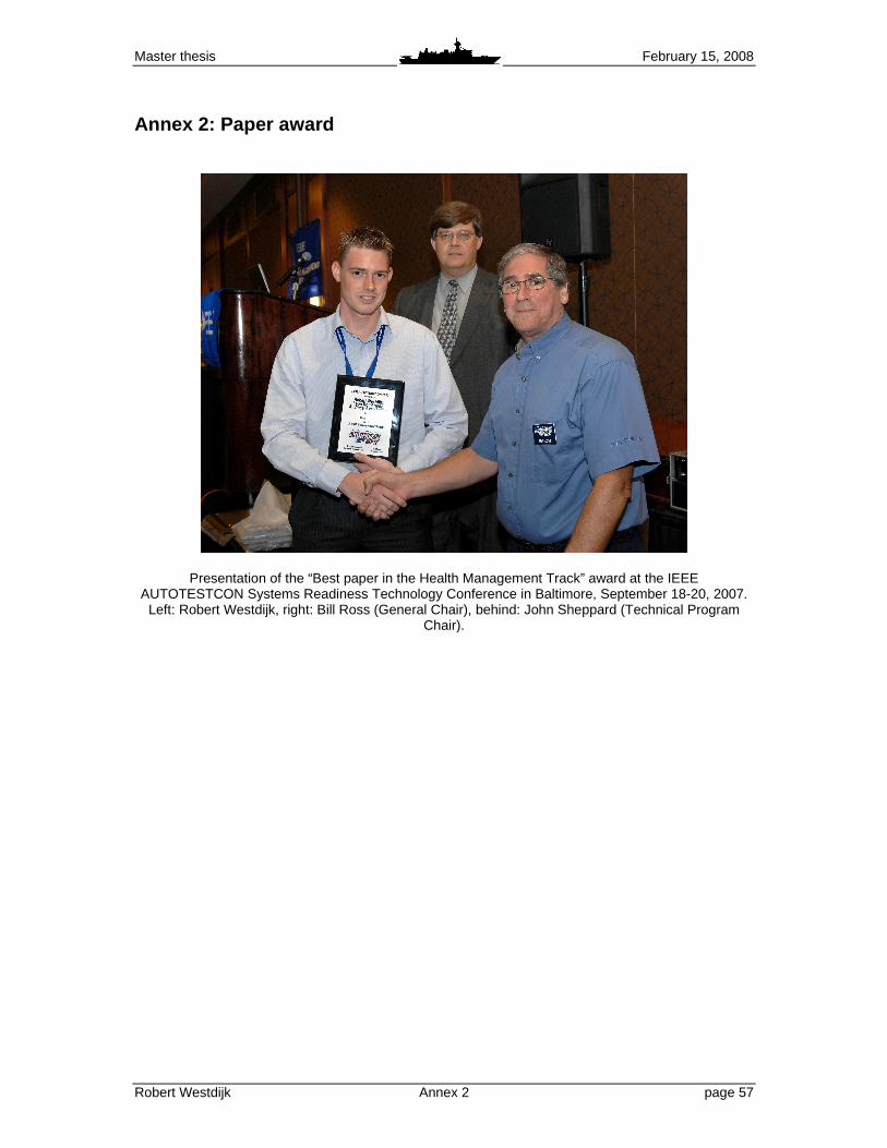
Master thesis February 15, 2008
Robert Westdijk Annex 2 page 57
Annex 2: Paper award
Presentation of the “Best paper in the Health Management Track” award at the IEEE AUTOTESTCON Systems Readiness Technology Conference in Baltimore, September 18-20, 2007.
Left: Robert Westdijk, right: Bill Ross (General Chair), behind: John Sheppard (Technical Program Chair).
Master thesis February 15, 2008
Robert Westdijk Annex 2 page 58

Master thesis February 15, 2008
Robert Westdijk Annex 3 page 59
Annex 3: Research report The following pages print the report “A Monitoring and Reasoning Framework for Applying Autonomic Computing in a Combat Management System”. This report has been published by the Royal Netherlands Naval College, which is part of the Netherlands Defence Academy (NLDA). The original transcript featured the paper “Applying Requirements Monitoring for Autonomic Computing in a Combat Management System” as an annex. This annex has been left out here, for obvious reasons.

Master thesis February 15, 2008
Robert Westdijk Annex 3 page 60

Master thesis February 15, 2008
Robert Westdijk Annex 3 page 61
Abstract
A combat management system (CMS) is the integrated software system that is used on naval platforms to manage the deployment of a variety of sensors, weapons and command systems. Faced with an increasing complexity of such naval combat systems and reduced manning concepts, the Centre for Automation of Mission-critical Systems (CAMS/Force Vision) commenced a feasibility study of autonomic computing in a CMS. This report presents the design, implementation and simulation of a diagnostics expert system prototype.
In previous work the ReqMon framework for requirements monitoring in a CMS was introduced, which is based on the use of the KAOS goal-oriented requirement engineering approach. This resulted in a JESS prototype for CMS software monitoring. By adopting this approach, the need for a complex system model is eliminated. Building on this prototype, the current report focuses on the implementation of a diagnostic reasoner for the software chain of Goalkeeper, a close-in weapon system deployed on Dutch frigates.
Simulations demonstrate that the combination of requirements monitoring and rule-based reasoning provide a solid foundation for various levels of autonomy in an existing combat management system.

Master thesis February 15, 2008
Robert Westdijk Annex 3 page 62
Contents Abstract 61 Contents 62 Introduction 62 1 Background 64
1.1 Autonomic computing 64 1.2 Requirements monitoring 65 1.3 ReqMon framework 65
2 Implementation 65 2.1 Model and prototype implementation 65 2.2 Monitor creation 67 2.2.1 Goal elicitation 67 2.2.2 Goal specification 68 2.2.3 Monitor definition 68 2.2.4 Monitor compilation 69 2.3 Diagnostic reasoner 69 3 Case Examples 71 3.1 Example 1: Supporting the developer 71 3.2 Example 2: Informing the operator 73 3.3 Example 3: Autonomizing the system 73 4 Discussion 75 5 Conclusion 77 Acknowledgements 78 References 78
Master thesis February 15, 2008
Robert Westdijk Annex 3 page 63
Introduction Nowadays, naval ships are becoming technologically more advanced due to a higher level of automation and a high-potential sensor suite of growing complexity. This results in combat management systems (CMS) becoming more and more complex. The CMS of a navel vessel is the collection of hardware and software which integrates the SEWACO (Sensor, Weapon and Command systems) subsystems, which are necessary for performing the various operational tasks. In contrast to the growing complexity of the software, most NATO fleets are faced with reduction in manning and material. This means that fewer personnel are available to operate and manage the CMS software. The ships of the Royal Netherlands Navy (RNLN) have an integrated combat system that allows for central operation of the ship’s subsystems. This high level of integration has led to the use of generic all-purpose workstations in the Operations Room. The CMS found on board Dutch naval vessels is developed at the Centre for Automation of Mission-critical Systems (CAMS/Force Vision) in Den Helder, The Netherlands. Autonomic computing or self-managing systems are systems that can manage themselves given high-level objectives. [12]. Self-management means that the system should be able to monitor its behavior, reason about it and adapt itself accordingly. Implementing self-management in a complex software system such as a CMS will create overhead, not only during run-time but also in the software development phase of the system. In order to overcome these drawbacks, the use of requirement monitoring is suggested. CAMS/Force Vision invests in research and development of software management tools to support maintenance at sea, taking into account the paradox of increased complexity versus reduced manning. Beside the development of software support tools for the system’s maintainers, completely autonomizing the system is also an issue of interest. The presented research in this report focuses mainly on the Guardion CMS, which is the latest version of the CMS software product line developed at CAMS/Force Vision. This report focuses on the development of a diagnostic expert reasoner for the CMS software system based on requirement monitoring. The reasoner will provide support for the software developer and the operational user, and will also provide a basis for applying autonomic computing. The main objectives of the presented research are:
- to define a model for the implementation of a diagnostic expert system based on requirements monitoring;
- to create a test environment for simulating and testing of the implementation model; - to develop a prototype of the diagnostic reasoner as a proof of concept.
The design and development of the diagnostic prototype are based on previous work, as documented in [25]9. In this work is has been shown how requirements monitoring is used to obtain diagnostic information from the software system. Using this information as problem features, the diagnostic expert system is able to detect problems in the software as they arise. This report is organized as follows. First, some background information is presented about autonomic computing and requirements monitoring. After that, the implementation model is shortly reviewed. Then the implementation is introduced, followed by a review of some example cases. Finally, the conclusions will be presented.
9 The complete transcript of this paper can be found in Annex I.

Master thesis February 15, 2008
Robert Westdijk Annex 3 page 64
1 Background10 1.1 Autonomic computing A software system with autonomic computing has the ability to modify its own behavior. Autonomic systems are also referred to as self-managing systems. There are four main aspects of autonomic computing: self-configuration, self-optimization, self-healing and self-protection [14]. This report focuses on the ability of self-healing, meaning that the system can examine, find, diagnose and react to system malfunctions [16]. The processes of self-management implements a control loop [1], [12], [13], [14]. The OODA loop can be applied here, which identifies four phases: Observe, Orient, Decide, and Act. System monitoring, is part of the Observe and Orient phases, while reasoning about monitored behavior is part of the Decide phase. Based on the information from the monitors, the automated reasoning component should produces some reconfiguration plan, which eventually must be executed within the monitored system. An autonomic system must be able to modify its own behavior. This means that the required system behavior must be defined, and that the system should be enabled to monitor this behavior. Both aspects introduce overhead. The first aspect involves the creation of some kind of system model. However, creating an accurate behavorial model of complex software systems such as the CMS is extremely difficult: these types of systems have grown too large to statically verify and analyze [22]. The second aspect means adding a monitoring framework to the software system. This not only introduces overhead at run-time, but also at development time. The increase in overhead is because incorporating new monitoring techniques or adapting existing ones also has a negative influence on both the time and budget of the development process. 1.2 Requirements monitoring To overcome the drawbacks of creating a complex system model and the increased development overhead when implementing autonomic computing, the use of requirements monitoring was proposed in [25]. Requirements monitoring is the tracking of the run-time behavior of a system in order to determine whether that running system is meeting its requirements [7], [19]. It is based on the notion that the behavior of a system is specified in the requirements of the system and consequently in its design. In this monitoring concept, the actual implementation of the software is of no concern, as long as the desired behavioral properties are accomplished. The following advantages are offered when autonomizing the CMS using requirements monitoring:
1. The opportunity to model system behavior on a high level without the creation of a complex behavioral model;
2. Limitation of workload required by designers and developers; 3. Good testability of the system for the current version of the CMS; 4. An approach to streamline the requirements elaboration process for future versions of the
CMS. A prerequisite for conducting requirements monitoring is the formalization of those requirements [13], [20]. This is part of the process of Requirements Engineering (RE). RE is concerned with the identification of real-world goals for functions of and constraints on software systems, the operationalization of these goals and the assignment of responsibilities for the resulting requirements [4], [17]. The goal-oriented RE method KAOS (Knowledge Acquisition in Automated Specification) is a frequently used technique in RE processes and requirement monitors development [5]. It is very well documented and various tools exist that support the sub processes and steps within this RE method, for instance [2], [11].
10 An elaborate description of requirements monitoring, the KAOS methodology and the ReqMon framework can be found in [23].

Master thesis February 15, 2008
Robert Westdijk Annex 3 page 65
KAOS uses object models, which can be represented using for instance UML (Unified Modelling Language) [10]. In essence, the functionally of the system is described in terms of goals. These goals should be operationalized by an agent11, which is an entity it the composite system. An agent can for instance be a specific software component or a part of the infrastructure. A goal can lead to one or more requirements. These relations can be visualized in a graph. Goal graphs offer a good overview of which elements of the system are responsible for certain tasks. They are scalable in size, for instance zooming in on parts of the system, and in depth, for instance by using general goals or really specific goals. 1.3 ReqMon framework Several monitoring systems adopt the KAOS approach to defining and formalizing software requirements. A summary of these systems can be found in [5]. For prototype development in [25], the ReqMon monitoring system as presented by W. Robinson in [19], [20], [21] has been adopted. ReqMon offers a programming interface that simplifies temporal event reasoning in real-time or near real-time [18]. It uses the JESS (Java Expert System Shell) programming language. ReqMon offers a compiler for the OCL Object Constraint Language. OCL is a well-known expression language that enables one to describe constraints on object-oriented models and other object modelling artefacts. It is part of the UML framework. The ReqMon OCL variant extends the UML 2.0 OCL specification to include the Dwyer patterns, which are based on a collection of common patterns found in requirement specifications [6]. These provide the means to express the linear-time temporal logic needed for the defining the KAOS goals. REQMON relies on event-based OCL semantics that have been extended to include temporal operations based on state and event semantics [21]. When deployed into the target system, the requirement monitors analyze the event stream that is generated by the monitored software component. These events contain information about the component’s processing. If a pattern of received events conflicts with the predefined pattern specified in the monitor definition, the property evaluation becomes false. This means that a monitored requirement is not satisfied, thus the system does not behave according to the design requirements. In a component-based and network-based software system such as the CMS, each component would be monitored by a daemon process containing all goal specifications for that particular component, as is depicted in Figure 1.
Figure 1: Data streams for a software component monitored by a ReqMon daemon. 2 Implementation 2.1 Model and prototype implementation The model as presented in [25] is reintroduced in Figure 2. It shows the transformation steps needed to implement and test the requirements monitoring for the CMS. For the deployment of monitors, the KAOS method is applied to extract goal information for software components based on the
11 A KAOS agent does not have the same qualifications as those of agents as defined in artificial intelligence (AI) research. KAOS agents can be any active component in the composite system, such as humans, devices or software.
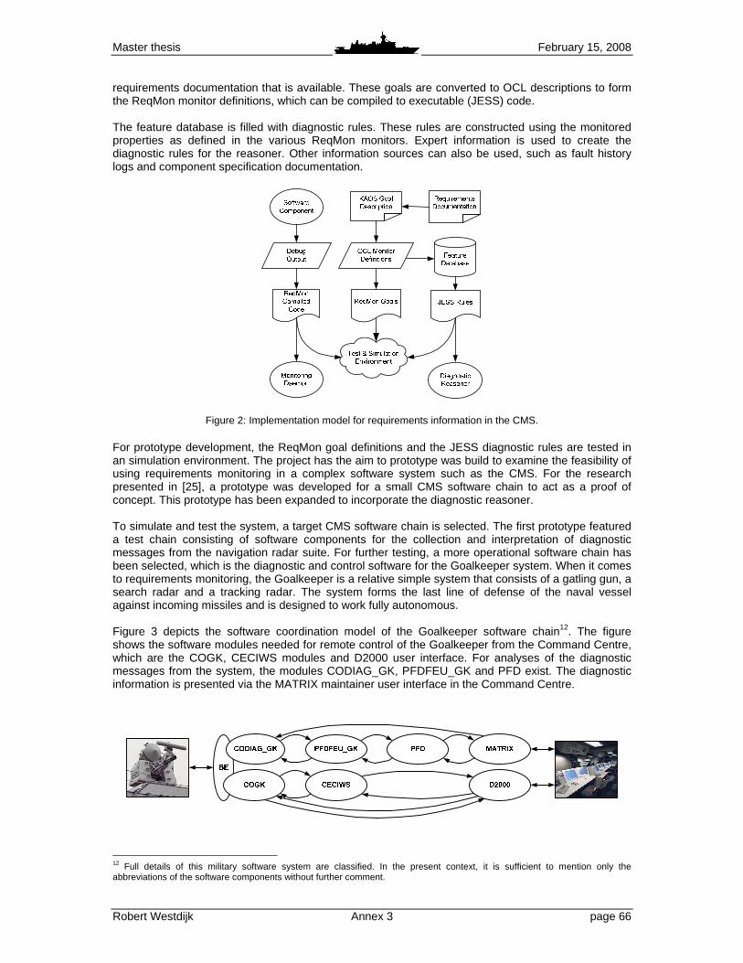
Master thesis February 15, 2008
Robert Westdijk Annex 3 page 66
requirements documentation that is available. These goals are converted to OCL descriptions to form the ReqMon monitor definitions, which can be compiled to executable (JESS) code. The feature database is filled with diagnostic rules. These rules are constructed using the monitored properties as defined in the various ReqMon monitors. Expert information is used to create the diagnostic rules for the reasoner. Other information sources can also be used, such as fault history logs and component specification documentation.
Figure 2: Implementation model for requirements information in the CMS. For prototype development, the ReqMon goal definitions and the JESS diagnostic rules are tested in an simulation environment. The project has the aim to prototype was build to examine the feasibility of using requirements monitoring in a complex software system such as the CMS. For the research presented in [25], a prototype was developed for a small CMS software chain to act as a proof of concept. This prototype has been expanded to incorporate the diagnostic reasoner. To simulate and test the system, a target CMS software chain is selected. The first prototype featured a test chain consisting of software components for the collection and interpretation of diagnostic messages from the navigation radar suite. For further testing, a more operational software chain has been selected, which is the diagnostic and control software for the Goalkeeper system. When it comes to requirements monitoring, the Goalkeeper is a relative simple system that consists of a gatling gun, a search radar and a tracking radar. The system forms the last line of defense of the naval vessel against incoming missiles and is designed to work fully autonomous. Figure 3 depicts the software coordination model of the Goalkeeper software chain12. The figure shows the software modules needed for remote control of the Goalkeeper from the Command Centre, which are the COGK, CECIWS modules and D2000 user interface. For analyses of the diagnostic messages from the system, the modules CODIAG_GK, PFDFEU_GK and PFD exist. The diagnostic information is presented via the MATRIX maintainer user interface in the Command Centre.
12 Full details of this military software system are classified. In the present context, it is sufficient to mention only the abbreviations of the software components without further comment.

Master thesis February 15, 2008
Robert Westdijk Annex 3 page 67
Figure 3: Software coordination model for the CMS Goalkeeper software chain. 2.2 Monitor creation For the creation of the ReqMon requirements monitors, the following step are carried out:
1. The goals of the monitored system are identified using the KAOS goal-oriented RE approach; 2. The defined goals are specified into requirement statements; 3. The ReqMon monitors are defined based on the goal specifications; 4. The monitor definitions are compiled to JESS code for use in the simulation environment.
2.2.1 Goal elicitation To create the ReqMon monitors, first the goals of a software component should be identified. For new software systems, goals could be drawn up using goal-oriented RE techniques during the design phase of the project. For existing systems such as the CMS, available documentation should be used. This should mainly be the requirements documentation, supported by other available technical information. For instance, for the monitors of the COGK module a requirement document and a technical description document were available [3], [8], [9]. Also, the expertise of the developer was used as domain expert knowledge input. Using the KAOS guidelines for goal elicitation, a goal graph can be created for a software system or part of a software system. Such a graph shows the goals and the agents assigned to operationalize these goals. Consider Figure 4, which shows the a partial KAOS goal graph for the Goalkeeper system, starting with the goal “Goalkeeper is remote controllable”13. The goals of the composite system are represented as parallelograms. They are operationalized by software agents, which are the octagons. This goal graph clearly shows which parts of a system functionally are achieved by which software components.
Figure 4: Partial KAOS goal graph for the Goalkeeper system.
2.2.2 Goal specification The goals have been defined in a goal structure, which is based on the structure used by KAOS. Examples can be found in for instance [5], [10], [11], [15]. KAOS offers a temporal specification language to define goal statements. However, it has been opted to use only informal goal definitions within the structures. This is because ReqMon itself offers an OCL language to formalize the goals. In this manner, the overhead for the software developer who has to define the goal statements is minimized. As has been stated, a goal can lead to one or more requirements and thus to one or more monitor definitions. For instance, the goal structure for “Goalkeeper status is known” defines five properties that should be monitored:
13 A complete overview of the Goalkeeper goal structures and goal graphs can be found in [24].
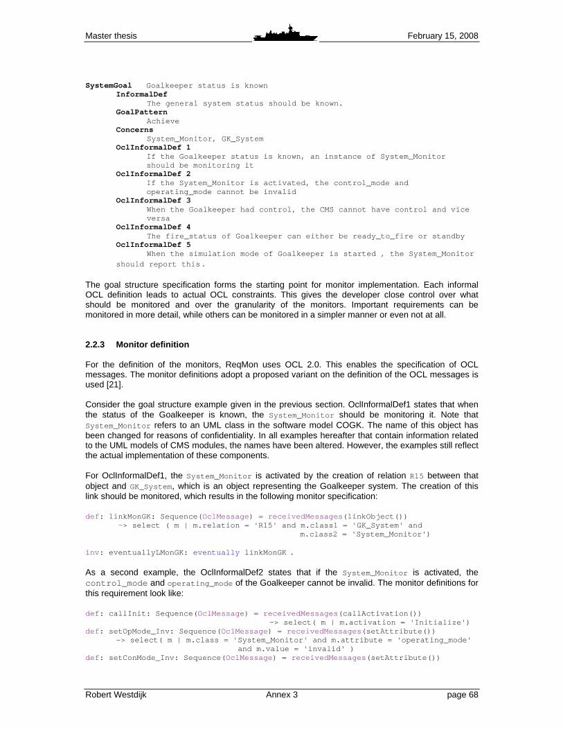
Master thesis February 15, 2008
Robert Westdijk Annex 3 page 68
SystemGoal Goalkeeper status is known
InformalDef The general system status should be known.
GoalPattern Achieve Concerns System_Monitor, GK_System OclInformalDef 1
If the Goalkeeper status is known, an instance of S ystem_Monitor should be monitoring it
OclInformalDef 2 If the System_Monitor is activated, the control_mod e and operating_mode cannot be invalid
OclInformalDef 3 When the Goalkeeper had control, the CMS cannot hav e control and vice versa
OclInformalDef 4 The fire_status of Goalkeeper can either be ready_t o_fire or standby
OclInformalDef 5 When the simulation mode of Goalkeeper is started , the System_Monitor
should report this . The goal structure specification forms the starting point for monitor implementation. Each informal OCL definition leads to actual OCL constraints. This gives the developer close control over what should be monitored and over the granularity of the monitors. Important requirements can be monitored in more detail, while others can be monitored in a simpler manner or even not at all. 2.2.3 Monitor definition For the definition of the monitors, ReqMon uses OCL 2.0. This enables the specification of OCL messages. The monitor definitions adopt a proposed variant on the definition of the OCL messages is used [21]. Consider the goal structure example given in the previous section. OclInformalDef1 states that when the status of the Goalkeeper is known, the System_Monitor should be monitoring it. Note that System_Monitor refers to an UML class in the software model COGK. The name of this object has been changed for reasons of confidentiality. In all examples hereafter that contain information related to the UML models of CMS modules, the names have been altered. However, the examples still reflect the actual implementation of these components. For OclInformalDef1, the System_Monitor is activated by the creation of relation R15 between that object and GK_System, which is an object representing the Goalkeeper system. The creation of this link should be monitored, which results in the following monitor specification: def : linkMonGK: Sequence( OclMessage ) = receivedMessages (linkObject()) -> select ( m | m.relation = 'R15' and m.cla ss1 = 'GK_System' and
m.class2 = 'System_Monitor')
inv : eventuallyLMonGK: eventually linkMonGK . As a second example, the OclInformalDef2 states that if the System_Monitor is activated, the control_mode and operating_mode of the Goalkeeper cannot be invalid. The monitor definitions for this requirement look like: def : callInit: Sequence( OclMessage ) = receivedMessages (callActivation())
-> select( m | m.activation = 'Initialize') def : setOpMode_Inv: Sequence( OclMessage ) = receivedMessages (setAttribute())
-> select( m | m.class = 'System_Monitor' and m.att ribute = 'operating_mode' and m.value = 'invalid' )
def : setConMode_Inv: Sequence( OclMessage ) = receivedMessages (setAttribute())

Master thesis February 15, 2008
Robert Westdijk Annex 3 page 69
-> select( m | m.class = 'System_Monitor' an d m.attribute = 'control_mode' and m.value = 'inv alid' inv : OpMode_after_Init: after (callInit) never setOpMode_Inv
inv : ConMode_after_Init: after (callInit) never setConMode_Inv . 2.2.4 Monitor compilation After definition, the monitors can be compiled to JESS code using the ReqMon compiler. In turn, the compiled JESS code can be made into a deployable monitor. This is not necessary for the test and simulation environment of the prototype. To verify the monitors, JESS scenarios are used. These scenarios simulate the event stream from the software components. The JESS scenarios can be created by combining various event entries like the own shown above. These scenarios are run in the ReqMon environment. Considering the setOpMode_Inv definition from the previous OCL example, the corresponding entry in a JESS simulation for the System_Monitor object would look like: (jassert (OclMessage (component " Goalkeeper_Control:COGK ") (subComponent " setAttribute(String) : void ") (parameters " class " " attribute " " value ")
(arguments " System_Monitor " " operating_mode " " invalid "))) . 2.3 Diagnostic Reasoner The diagnostic reasoning component uses the monitored properties as features. The evaluation of these features by the deployed requirement monitors provide the information for further reasoning. For prototype development, the JESS language offers a rule engine and scripting environment to create rule-based expert systems. In this system, the features will be represented as facts. A set of rules will be defined, which models the knowledge about the target system. This knowledge comes from domain experts, requirements documentation, technical documentation on the software components, and other sources available. The ReqMon daemons will evaluate the monitored requirement properties. The properties will either be satisfied or unsatisfied given the monitored event stream from the software components. The evaluated values will be sent to the reasoner, which in turn evaluates the property information. The combination of these property events will cause the defined expert rules to fire. This process is depicted in Figure 5.
Figure 5: Information flow in the monitoring and reasoning framework, with a simple pseudo-code example. As an example, consider the goal structure that was introduced in Section 3.2.2. Suppose that after relation R15 has been created, an invalid value for the control_mode or operating_mode of the Goalkeeper indicates the manifestation of some known problem in the system. For all of these

Master thesis February 15, 2008
Robert Westdijk Annex 3 page 70
properties, an OCL monitor definition has been created. However, combining these properties requires a JESS rule definition: (defrule GK-known-problem-detected (and (or (monitor-event (property OpMode_after_In it)(evaluated FALSE)) (monitor-event (property ConMode_after_I nit)(evaluated FALSE))) (monitor-event (property eventuallyLMonGK)(e valuated TRUE))) =>
(assert (Goalkeeper-known-problem-has-been-detect ed))) . In this case, the defined rule only uses information from a single ReqMon daemon which is instantiated to monitor the COGK module. As is shown in Figure 5, the reasoner can receive property evaluations from multiple instances of the ReqMon daemon. This allows detection of diagnostic problem throughout the software system.

Master thesis February 15, 2008
Robert Westdijk Annex 3 page 71
3 Case Examples In [25] it was stated, that the information extracted by requirements monitoring can have multiple uses, as depicted in Figure 6: 7. Requirements monitoring during software development and testing can provide useful information
for the developer; 8. The run-time goal information can be redirected to the operator to provide feedback about system
performance and errors; 9. The collected goal information can be used by an AI system to make a first diagnosis for the
software maintenance technicians on board in case of software malfunctions.
Figure 6: Data flow of diagnostic information in the requirements monitoring system. To illustrate how the diagnostic reasoning component would operate, three example cases are presented here. Each case offers an example of one of the uses for requirements monitoring as described above. 3.1 Example 1: Supporting the developer During CMS software development, incremental tests are carried out. The white and black box tests for a single component can be carried out locally in the development environment. Integration tests can be done on the so-called Target system at CAMS/Force Vision, on which the Guardion CMS software is installed. It resembles the Command Centre as found aboard Dutch naval vessels. Software acceptance are always carried on the actual CMS on board the ships. When applying requirements monitoring as proposed in this research, the developer is enabled to implement monitoring definitions in the software based on the specified requirements. Furthermore, rule definitions can be composed. These would be added to the existing rule base of the diagnostic reasoning component, which resides somewhere within the CMS. This provides the developer with extra information when testing and debugging his software component in the integrated environment. In Figure 3, the Goalkeeper software chain was depicted. The software modules for Goalkeeper diagnostics are CODIAG_GK, PFDFEU_GK and PFD. The PFDFEU_GK is the database component, which holds information about possible diagnostic messages that can be received via the CODIAG_GK from the Goalkeeper system. The requirement documentation for both components specify which messages should be contained in the database. In the CODIAG_GK, each message is represented by an instance of a generic message object class, of which the creation can be monitored. The PFDFEU_GK receives these generic messages and maps these as a condition on a Goalkeeper technical component, also represented by an object class. This can also be monitored. Using these OCL monitor definitions, a rule can be created that checks whether the complete message set is presented in the message database: (defrule message-not-in-database " Message is not in the diagnostic database " (and (or (monitor-event (property Msg_response_F 1_True)(evaluated TRUE)) (monitor-event (property Msg_response_F 1_False)(evaluated TRUE)) (monitor-event (property Msg_response_F 2_True)(evaluated TRUE)) (monitor-event (property Msg_response_F 2_False)(evaluated TRUE)))
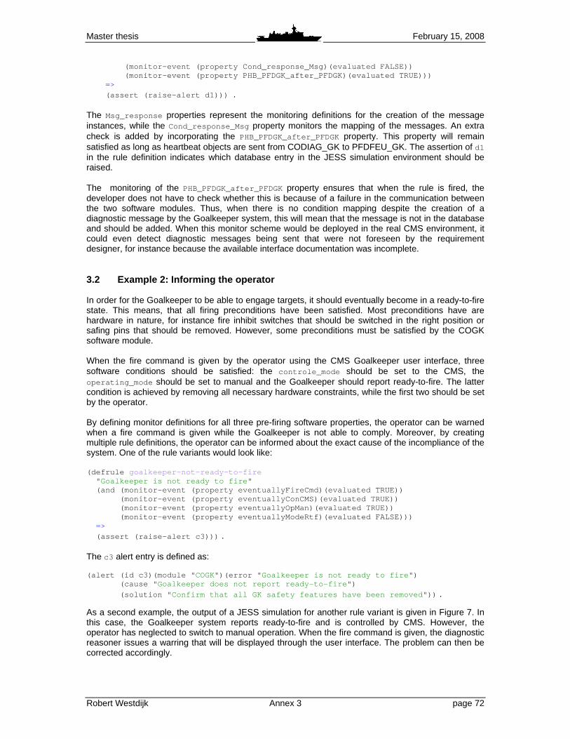
Master thesis February 15, 2008
Robert Westdijk Annex 3 page 72
(monitor-event (property Cond_response_Msg) (evaluated FALSE)) (monitor-event (property PHB_PFDGK_after_PF DGK)(evaluated TRUE))) =>
(assert (raise-alert d1))) . The Msg_response properties represent the monitoring definitions for the creation of the message instances, while the Cond_response_Msg property monitors the mapping of the messages. An extra check is added by incorporating the PHB_PFDGK_after_PFDGK property. This property will remain satisfied as long as heartbeat objects are sent from CODIAG_GK to PFDFEU_GK. The assertion of d1 in the rule definition indicates which database entry in the JESS simulation environment should be raised. The monitoring of the PHB_PFDGK_after_PFDGK property ensures that when the rule is fired, the developer does not have to check whether this is because of a failure in the communication between the two software modules. Thus, when there is no condition mapping despite the creation of a diagnostic message by the Goalkeeper system, this will mean that the message is not in the database and should be added. When this monitor scheme would be deployed in the real CMS environment, it could even detect diagnostic messages being sent that were not foreseen by the requirement designer, for instance because the available interface documentation was incomplete. 3.2 Example 2: Informing the operator In order for the Goalkeeper to be able to engage targets, it should eventually become in a ready-to-fire state. This means, that all firing preconditions have been satisfied. Most preconditions have are hardware in nature, for instance fire inhibit switches that should be switched in the right position or safing pins that should be removed. However, some preconditions must be satisfied by the COGK software module. When the fire command is given by the operator using the CMS Goalkeeper user interface, three software conditions should be satisfied: the controle_mode should be set to the CMS, the operating_mode should be set to manual and the Goalkeeper should report ready-to-fire. The latter condition is achieved by removing all necessary hardware constraints, while the first two should be set by the operator. By defining monitor definitions for all three pre-firing software properties, the operator can be warned when a fire command is given while the Goalkeeper is not able to comply. Moreover, by creating multiple rule definitions, the operator can be informed about the exact cause of the incompliance of the system. One of the rule variants would look like: (defrule goalkeeper-not-ready-to-fire " Goalkeeper is not ready to fire " (and (monitor-event (property eventuallyFireCmd)( evaluated TRUE)) (monitor-event (property eventuallyConCMS)(e valuated TRUE)) (monitor-event (property eventuallyOpMan)(ev aluated TRUE)) (monitor-event (property eventuallyModeRtf)( evaluated FALSE))) =>
(assert (raise-alert c3))) . The c3 alert entry is defined as: (alert (id c3)(module " COGK")(error " Goalkeeper is not ready to fire ") (cause " Goalkeeper does not report ready-to-fire ")
(solution " Confirm that all GK safety features have been remov ed")) .
As a second example, the output of a JESS simulation for another rule variant is given in Figure 7. In this case, the Goalkeeper system reports ready-to-fire and is controlled by CMS. However, the operator has neglected to switch to manual operation. When the fire command is given, the diagnostic reasoner issues a warring that will be displayed through the user interface. The problem can then be corrected accordingly.

Master thesis February 15, 2008
Robert Westdijk Annex 3 page 73
Figure 7: Example output from a JESS simulation.
3.3 Example 3: Autonomizing the system As mentioned before, the Goalkeeper is designed to operate autonomously . This means that it has its own suite of sensors to detect and track possible threats. An automatic surveillance sector can be defined, but it is also possible to cue hostile tracks other sensors. To keep tracking its targets, the Goalkeeper must be aware of the heading of the ship. The heading is one of the attribute values of the Own_Ship_Data object class, which can be found throughout the CMS software. This information is supplied by two redundant hardware sources, which interface with the CMS via two different instances of the same software module, COOSD. Thus, the goal “Own Ship Data is provided” is operationalized by the COOSD module, as can been seen in Figure 4. To check if the COGK and CECIWS components receive the data, monitors check the creation of the input object, which is a direct mapping of Own_Ship_Data instances on the output of COOSD. To ensure that the COOSD module is still running, the process heartbeat object is also monitored. If the process heartbeat is created while the input objects are not, there is a problem. The corresponding rule definition is stated as follows: (defrule no-own-ship-data " Goalkeeper does not receive Own Ship data " (and (monitor-event (property OSDCo_after_OSDCo)( evaluated FALSE)) (monitor-event (property OSDCe_after_OSDCe)( evaluated FALSE)) (monitor-event (property PHB_COSD_after_PHB_ COSD)(evaluated FALSE))) =>
(assert (raise-alert c12))) . Using the ReqMon monitors and the rule definition stated above, the operator could be warned that the Goalkeeper system is not receiving any heading information. However, what would really be desirable, is for the CMS system itself to react to this error. If the COOSD process is running, but no instances of Own_Ship_Data are received by COGK and CECIWS, then the root cause of the problem will properly be software-related or infrastructural. By enhancing the system with autonomic computing, it can try to establish the cause of the problem. Even when the system’s effort fails, the diagnostic information retrieved by the system’s actions will increase the knowledge of the problem for the maintainers onboard, hence decreasing the number of fault hypotheses for them to check. To close the OODA loop as depicted in Figure 8, the system must be able to perform reconfiguration actions. This report focuses on the ability of self-healing. Using requirements monitoring, the system can examine, find and diagnose problems. By adding a reconfiguration component, it should be able to react to system malfunctions by carrying out some reconfiguration plan.
Jess> INFO: Property eventuallyOpMan is evaluated F ALSE INFO: Property eventuallyConCMS is evaluated TRUE INFO: Property eventuallyModeRtf is evaluated TRUE INFO: Property eventuallyFireCmd is evaluated TRUE ALERT: Error in module COGK ALERT: Description: Goalkeeper is not ready to fire ALERT: Cause: Goalkeeper is not in mode Manual ALERT: Solution: Select Goalkeeper Manual mode ~ Jess> INFO: Property eventuallyOpMan is evaluated T RUE NOTICE: Error "Goalkeeper is not ready to fire" is no longer valid

Master thesis February 15, 2008
Robert Westdijk Annex 3 page 74
programming
events
JESS reasoner diagnoses
software faults
Software modules sent
programming events
ReqMon monitors
evaluate event patternsReconfiguration component
takes appropriate actions ACT
evaluated
properties
ORIENT
OBSERVE
DECIDEasserted
diagnostic facts
reconfiguration
actons
Figure 8: OODA loop for autonomic computing in the simulation environment. Given the problem described above, a simple example of a reconfiguration plan is presented in Figure 10. This plan uses only the knowledge present based on the defined monitors in the Goalkeeper software chain. It assumes that COGK and CECIWS are running on the same node, while COOSD is instantiated on a different node. First, the MTL on the node of COOSD is restarted. The MTL is a software process that provides for the relaying of component objects. If this does not help, the MTL on the Goalkeeper software node is restarted. The next step would be to restart the COOSD process itself. It this fails, the CECIWS is restarted on another node. If this helps, the COGK is also re-instantiated14. However, if all actions fail to solve the problem, the maintainer is warned by the system. The reconfiguration actions are disclosed, giving the maintainer a starting point for further fault localization. Figure 9 shows only one example of what a reconfiguration plan could look like. If more knowledge is added, the scheme can get more elaborate. For instance, the fact that other software modules do or do not receive the Own_Ship_Data object reduces the set of root cause hypotheses. Furthermore, more intelligent techniques can be used in the planning algorithm, for instance as presented in [1].
Figure 9: Example of a simple reconfiguration plan for the “no-own-ship-data” failure.
14 The current CMS version has dynamic reconfiguration capabilities, but the implementation of dynamic reconfiguration architectures is outside the scope of this research.

Master thesis February 15, 2008
Robert Westdijk Annex 3 page 75
4 Discussion The research presented in this report is the continuation of the work presented in [25], where the use of requirements monitoring as a basis for applying autonomic computing was discussed. This previous research involved the creation of a ReqMon prototype, which was test on a simple CMS software chain. It was stated that the ReqMon prototype should be tested on more complicated CMS software components to get more tangible results. With the creation of the diagnostic reasoning component and by presenting some case examples, the benefits of using requirements monitoring as a basis for further autonomic development have been made clear. These are mainly the scalability of the approach, the elimination of the need for a comprehensive system model and the relative simple manner in which monitoring and reasoning capabilities can be defined. Also, the feasibility of the implementation of requirements monitoring is shown. However, some reflections on the use of the proposed methodology are considered here. The presented implementation model is scalable for larger systems that the software chain on which is was applied in this report. However, the creation of the case examples have proven that domain-specific knowledge is still required in certain phases of monitor implementation, which reduces the advantage of limited implementation overhead in the software development phase. On the other hand, much can be regained by applying goal-oriented RE techniques throughout the various stages of the software development process. Beside the need for domain-specific knowledge in the development phase, system complexity is also an issue. The OCL statements and corresponding rule definitions presented in this work are simple in nature. For a proof of concept, they provide enough complexity to base conclusions on, but when applying the concept to large-scale software systems, their complexity will increase. An increase in complexity will lead to more effort to develop and test the monitor specification and rule definitions. By offering automated tools to the developer, the increase in complexity can be reduced. Also, more elaborate AI techniques than the proposed rule-based approach could be used. Furthermore, the scalability of the ReqMon requirements monitoring framework should be applied here, meaning that important requirements can be monitored more elaborately than less important requirements. ReqMon assumes that there is a static and dynamic traceability between the software objects and the stated requirements [19]. Static traceability means that monitored entities can be traced back to their object definition in the programming code. Dynamic traceability means that the monitor should be able to distinguish between different instances of a defined object class. The first assumption is satisfied by all software that has been developed using a modelling technique. To satisfy the second assumption, the software code should be instrumented to send programming events for monitoring. For the CMS software, the desired instrumentation can be added since the compiler is developed in-house. However, instrumentation could be an issue for other systems. ReqMon offers support for instrumentation only for Java-based programs. For other types of applications, instrumentation should be added by other means. This is considered to be outside the scope of this research. An autonomic computing software system is designed to work autonomously and automatically. This essentially means, that there is no need human interference. However, the complete elimination of human decisions in a military (weapon) system is often undesirable. For instance, after a missile has been launched by a naval vessel, automatic reconfiguration of the CMS is out of the question while the ship is offering missile guidance. More in general, the operator’s and maintainer’s grasp on the system decreases when the system’s autonomic ability increases. Instead of a full autonomic software system, a semi-autonomic mode could be introduced. This means that the system does not actually carry out any reconfiguration actions, but notifies the maintainer when a fault occurs. The system can then advise the maintainer and suggest which actions should be taken to correct the fault. In this work, the issue of dynamic reconfiguration was only shortly mentioned. In reality, this is an entire research field with many difficult aspects. The implementation of dynamic reconfiguration capabilities in a complex system such as the CMS requires great effort. Currently, work is been undertaken by CAMS/Force Vision to implement dynamic master/slave switching between instantiations of CMS software components, but this is not yet a full dynamic reconfiguration ability.
Master thesis February 15, 2008
Robert Westdijk Annex 3 page 76
In the presented cases, some examples of simple software reconfiguration actions were given. To solve more complex problems in a software system, these types of actions will be not be enough. The reconfiguration component should have the ability to take more elaborate actions. For instance, the ability to resend certain objects, or the ability to perform certain actions for which normally a operator should be required. The implementation problem of these abilities is outside the scope of this report, but adding them is both feasible and practicable in the case of CMS software modules. In mission-critical systems such as the CMS, system monitoring and diagnostics is crucial. These systems should be viewed in a composite manner, because the software and hardware of the systems are both needed. Also, faults occurring in hardware can have effects on the software, and vice versa. Although goal-oriented RE techniques such as KAOS create a composite view on the system, only the software monitoring aspect has been researched in this work. This is because reasoning about the state of the software in respect to its desired behavior is very difficult, but reasoning about the whole composite system would be even more difficult when using only a single monitoring framework.

Master thesis February 15, 2008
Robert Westdijk Annex 3 page 77
5 Conclusion This report describes a research project which aims to examine the use of requirements monitoring for applying autonomic computing of complex software systems. To implement autonomic computing, the use of requirements monitoring combined with a rule-based diagnostic reasoner has been proposed. A model has been defined, identifying the transformation steps needed for the implementation of autonomic computing based on requirements monitoring. This model proposes the use of the KAOS goal-orient requirements engineering (RE) approach to define goals for the software components. Monitoring is done using the ReqMon requirements monitoring framework to create software monitor specification. Reasoning capability is added by a JESS rule-based diagnostic reasoner. For testing and simulation of the proposed implementation, a prototype has been developed. The event stream from the CMS software components can be simulated, as well as the evaluated requirements properties as they are received by the reasoner. The information extracted by applying requirements monitoring to a software system can be used for software testing during software component development. Furthermore, the goal information can provide feedback to the operator during run-time. Last, the properties monitored by the requirements monitoring framework can be used for diagnostic reasoning about the software system. To demonstrate the uses of the proposed monitoring framework, three case examples have been provided for the Goalkeeper close-in weapon system. The first case features a problem in the Goalkeeper diagnostic software during the development phase. By checking the creation of object instances representing diagnostic messages, the integrity of the diagnostic message database is checked. The second case introduces the preconditions that needs to be satisfied in order for the Goalkeeper to fire. By monitoring the value of object attributes representing these preconditions, the operator is warned when the are not met. The third case focuses on autonomizing the software. When heading information is no longer sent to the Goalkeeper software modules, a reconfiguration plan could be executed to solve this problem. It can be concluded that an implementation of autonomic computing in a CMS is feasible; this was demonstrated with and discussed by combining requirements monitoring with rule-based diagnostic reasoning.

Master thesis February 15, 2008
Robert Westdijk Annex 3 page 78
Acknowledgements This work is sponsored by the Centre for Automation of Mission-critical Systems, Force Vision. The authors like to thank Frank Zwarthoed, the developer and domain expert for the CMS Goalkeeper software, for his support. References [1] Arshad, N., “A Planning-Based Approach to Failure Recovery in Distributed Systems”, PhD
Thesis, 2006. University of Colorado, Department of Computer Science, 2006. [2] CETIC, Centre of Excellence in Information and Communication Technologies, “An Overview
of the FAUST Toolbox”, http://www.cetic.be/internal220.html. http://www.cetic.be, last visited December 2007.
[3] COGK-team., “COGK allocated DAISY-NT requirements”, CAMS/Force Vision. September 11, 2001 (internal report).
[4] Darimont R, and Lamsweerde, A. van, “Formal Refinement Patterns for Goal-driven Requirements Elaboration”, Proceedings of the 4th ACM Symposium on the Foundations of Software Engineering, pp.179-190, 1996.
[5] Dingwall-Smith, A., “Run-Time Monitoring of Goal-Oriented Requirements”, PhD Thesis, June 2006. University College London, Department of Computer Science, 2006.
[6] Dwyer, M., Avrunin, S. and Corbbet, J., “Patterns in property specifications for finite-state verification”, Proceedings of the Twenty-First International Conference on Software Engineering, pp. 411-420, 1999.
[7] Fickas, S. and Feather, M., “Requirements monitoring in dynamic systems”, Proceedings of the IEEE International Conference on Requirements Engineering, pp. 140-147, 1995.
[8] Franken, M., “CoGK outline v01”, CAMS/Force Vision, Augustus 19, 2003 (internal report, CONFIDENTIAL).
[9] Franken, M., “CoGK development v04”, CAMS/Force Vision, June 23, 2005 (internal report, CONFIDENTIAL).
[10] Heaven, W. and Finkelstein, A., “A UML profile to support requirements engineering with KAOS”, IEEE Proceedings - Software, vol. 151, pp. 10-27, 2004.
[11] “A KAOS Tutorial”, September 5, 2003. http://www.objectiver.com/download/documents/ KaosTutorial.pdf. Objectiver website, http://www.objectiver.com, last visited December 2007.
[12] Kephart, J. and Chess, D., “The Vision of Autonomic Computing”, IEEE Computer, pp 41-50, January 2003.
[13] Lapouchnian, A., Liaskos, S., Mylopoulos, J. & Yu, Y., “Towards Requirement-Driven Autonomic Systems Design”, Design and Evolution of Autonomic Application Software, May 21, 2005.
[14] Lapouchnian, A., “Goal-oriented Requirements Engineering: An Overview of the Current Research”. Depth Report, University of Toronto, 2005.
[15] Letier,E., “Reasoning about Agents in Goal-Oriented Requirements Engineering”, PhD Thesis, May 2001. Université Catholique de Louvain, Dépt. Ingénierie Informatique, 2001.
[16] Murch, R., “Autonomic Computing”, 2004. IBM Press/Prentice Hall, New Jersey. [17] Nuseibeh, B. and Easterbrook, S., “Requirements Engineering: A Roadmap”, International
Conference on Software Engineering, June 4-11, 2000. [18] Robinson W., “About this project”, http://wrobinson.cis.gsu.edu/projects/reqmon/Home/
AboutThisProject/tabid/401/Default.aspx. ReqMon website: http://wrobinson.cis.gsu.edu/ projects/reqmon, last visited December 2007.
[19] Robinson, W., “Monitoring Software Requirements using Instrumented Code”, Proceedings of the 35th Hawaii International Conference on System Sciences, January 7-10, 2002.
[20] Robinson, W., “Implementing Rule-based Monitors within a Framework for Continuous Requirements Monitoring”, Proceedings of the 38th Hawaii International Conference on Systems Sciences, 2005.
[21] Robinson, W., “Monitoring Software Quality Requirements”, 2007. Georgia State University, Department of Computer Information Systems, 2007.
[22] Ward, M. and Heineman, G., “A Framework for Visualizing the Behavior of Component-Based Software Systems”, Conference on Object-Oriented Programming, Systems, Languages and Applications, October 14-18, 2001.
Master thesis February 15, 2008
Robert Westdijk Annex 3 page 79
[23] Westdijk, R., “Autonomic Computing for the Combat Management System based on Requirements Monitoring”, Literature study, January 28, 2006. Delft University of Technology, Department of Electrical Engineering, Mathematics and Computer Science, 2006.
[24] Westdijk, R., “Thesis Progress Report”, CAMS/Force Vision, August 8, 2007 (internal report). [25] Westdijk, R., Rothkrantz, L. and Leijen, A.V. van, “Applying requirements monitoring for
autonomic computing in a combat management system”, IEEE AUTOTESTCON Systems Readiness Technology Conference, pp. 349-358, September 17-20, 2007.

Master thesis February 15, 2008
Robert Westdijk Annex 3 page 80
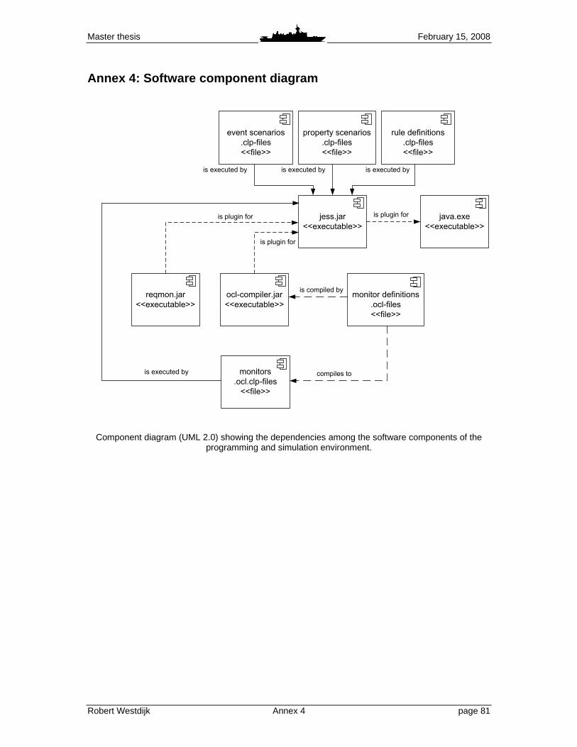
Master thesis February 15, 2008
Robert Westdijk Annex 4 page 81
Annex 4: Software component diagram
monitor definitions
.ocl-files
<<file>>
reqmon.jar
<<executable>>
jess.jar
<<executable>>
java.exe
<<executable>>
ocl-compiler.jar
<<executable>>
monitors
.ocl.clp-files
<<file>>
event scenarios
.clp-files
<<file>>
is plugin for
is plugin for is plugin for
is compiled by
compiles tois executed by
property scenarios
.clp-files
<<file>>
is executed by is executed by
rule definitions
.clp-files
<<file>>
is executed by
Component diagram (UML 2.0) showing the dependencies among the software components of the programming and simulation environment.