renewable energy, permanent magnet dc motor · the following safety symbols may be used in this...
TRANSCRIPT

Renewable Energy
Permanent Magnet DC Motor
Courseware Sample 86357-F0
A


RENEWABLE ENERGY
PERMANENT MAGNET DC MOTOR
Courseware Sample
by the staff
of Lab-Volt Ltd.
Copyright © 2011 Lab-Volt Ltd.
All rights reserved. No part of this publication may be reproduced, in any form or by any means, without the prior written permission of Lab-Volt Ltd.
Printed in CanadaNovember 2011

A Permanent Magnet DC Motor v
Safety Symbols
The following safety symbols may be used in this manual and on the Lab-Volt equipment:
Symbol Description
DANGER indicates a hazard with a high level of risk which, if not avoided, will result in death or serious injury.
WARNING indicates a hazard with a medium level of risk which, if not avoided, could result in death or serious injury.
CAUTION indicates a hazard with a low level of risk which, if not avoided, could result in minor or moderate injury.
CAUTION used without the Caution, risk of danger sign , indicates a hazard with a potentially hazardous situation which, if not avoided, may result in property damage.
Caution, risk of electric shock
Caution, hot surface
Caution, risk of danger
Caution, lifting hazard
Caution, hand entanglement hazard
Direct current
Alternating current
Both direct and alternating current
Three-phase alternating current
Earth (ground) terminal
Protective conductor terminal
Frame or chassis terminal

Safety Symbols
vi Permanent Magnet DC Motor A
Symbol Description
Equipotentiality
On (supply)
Off (supply)
Equipment protected throughout by double insulation or reinforced insulation
In position of a bi-stable push control
Out position of a bi-stable push control

A Permanent Magnet DC Motor vii
Foreword
Rotating machines such as electrical motors and generators (or alternators) are found in almost every sector of the industry. The basic principles of operation of rotating machines have been known for almost two centuries. Rotating machines operate due to the interaction between magnetic fields and current-carrying conductors, and are split into two basic categories: motors and generators.
Permanent magnet dc motors are rotating machines that operate using direct current (i.e., they are dc powered). They can be used as either generators or motors. Permanent magnet dc motors are rugged components that are easy to connect and require little maintenance. They are found in a variety of applications, such as battery charging, small electric vehicles, windmill technology, mobility scooters, pumps, machine tools, kitchen appliances, optical equipment, etc.
The present course introduces the student to permanent magnet dc motors used as either generators or motors. The course covers the construction, operating principles, and characteristic curves of permanent magnet dc motors related to each of these two operating modes.
The equipment for the course mainly consists of the Permanent Magnet DC Motor and the Four-Quadrant Dynamometer/Power Supply. The operation of the motor is controlled by using the Lab-Volt LVDAC-EMS software, which also provides the instrumentation required to record the experimental data and plot characteristic curves.


A Permanent Magnet DC Motor ix
Table of Contents
Introduction� Permanent Magnet DC Motors .................................................... 1�
DISCUSSION OF FUNDAMENTALS ....................................................... 1�Work, torque, and power .......................................................... 1�Basic dc motor operation ......................................................... 3�Permanent magnet dc motors .................................................. 5�
Exercise 1� Prime Mover and Brake Operation ............................................. 7�
DISCUSSION ..................................................................................... 7�Introduction to the Four-Quadrant Dynamometer/Power Supply ...................................................................................... 7�
Two-quadrant constant-torque brake .......................................... 7�Clockwise constant-speed prime mover/brake ........................... 8�Counterclockwise constant-speed prime mover/brake ............... 9�
Speed, torque, and mechanical power measurements using the Four-Quadrant Dynamometer/Power Supply ......... 10�
Motor operation ........................................................................ 10�Generator operation ................................................................. 10�
PROCEDURE ................................................................................... 11�Setup and connections .......................................................... 11�Two-quadrant, constant-torque brake operation .................... 13�Constant-speed prime mover operation ................................ 16�Constant-speed prime mover driving a loaded generator ..... 19�
Exercise 2� Permanent Magnet DC Motor Operating as a Generator ........ 25�
DISCUSSION ................................................................................... 25�Permanent magnets ............................................................... 25�Magnetic field around a conductor ......................................... 26�Magnetic field in a loop of wire (electromagnet) .................... 27�Electromagnetic induction ...................................................... 29�Construction of a permanent magnet dc motor ..................... 32�Permanent magnet dc motor operating as a generator ......... 34�Reducing the fluctuations of the generated dc voltage .......... 37�Characteristic of the generated voltage as a function of the rotation speed .................................................................. 39�Torque opposing rotation in a permanent magnet dc motor operating as a generator ......................................... 39�Opposition torque-versus-current characteristic .................... 41�
PROCEDURE ................................................................................... 42�Electromagnetic induction phenomenon ................................ 42�Opposition to rotation ............................................................. 43�Voltage-versus-speed characteristic of a permanent magnet dc motor operating as a generator ............................ 43�
Clockwise rotation .................................................................... 45�Counterclockwise rotation ........................................................ 46�

Table of Contents
x Permanent Magnet DC Motor A
Torque-versus-current characteristic of a permanent magnet dc motor operating as a generator ............................ 47�
Exercise 3� Permanent Magnet DC Motor Operating as a Motor ............... 53�
DISCUSSION ................................................................................... 53�Operation of a permanent magnet dc motor as a motor ........ 53�Magnetic field produced in the armature ............................... 54�Armature rotation resulting from the interaction between the magnetic fields of the armature and permanent magnets ................................................................................. 56�Equivalent diagram of a permanent magnet dc motor ........... 58�
PROCEDURE ................................................................................... 61�Setup and connections .......................................................... 62�Speed-versus-voltage characteristic of a permanent magnet dc motor operating as a motor .................................. 63�
Clockwise rotation ..................................................................... 63�Counterclockwise rotation ......................................................... 65�
Torque-versus-current and speed-versus-torque characteristics of a permanent magnet dc motor operating as a motor .............................................................. 66�
Clockwise rotation ..................................................................... 67�Counterclockwise rotation ......................................................... 68�
Appendix A� Equipment Utilization Chart ...................................................... 73�
Appendix B� Glossary of New Terms .............................................................. 75�
Appendix C� Circuit Diagram Symbols ........................................................... 77�
Appendix D� Preparation of the Lead-Acid Battery Pack ............................. 81�Slow (overnight) charging method ......................................... 81�Fast charging method ............................................................ 81�Sulfation test .......................................................................... 83�
Bibliography ......................................................................................................... 85�
We Value Your Opinion!....................................................................................... 87�

Sample Exercise
Extracted from
Student Manual


A Permanent Magnet DC Motor 25
When you have completed this exercise, you will be familiar with the construction of permanent magnet dc motors as well as their operation as generators.
The Discussion of this exercise covers the following points:
� Permanent magnets�� Magnetic field around a conductor�� Magnetic field in a loop of wire (electromagnet)�� Electromagnetic induction�� Construction of a permanent magnet dc motor�� Permanent magnet dc motor operating as a generator�� Reducing the fluctuations of the generated dc voltage�� Characteristic of the generated voltage as a function of the rotation
speed�� Torque opposing rotation in a permanent magnet dc motor operating as
a generator�� Opposition torque-versus-current characteristic�
Permanent magnets
A permanent magnet is a piece of iron or metal surrounded by a magnetic field, as Figure 13 shows. This magnetic field is constant, i.e., it persists naturally without the need of an electrical current. The magnet has a north (N) pole and a south (S) pole. These poles are situated near the ends of the magnet where the magnetic field strength is the greatest.
Figure 13. A permanent magnet has two poles called north (N) and south (S).
Permanent Magnet DC Motor Operating as a Generator
Exercise 2
EXERCISE OBJECTIVE
DISCUSSION OUTLINE
DISCUSSION
South (S) pole
North (N) pole
Magnetic fieldMagnetic field N
S

Exercise 2 – Permanent Magnet DC Motor Operating as a Generator � Discussion
26 Permanent Magnet DC Motor A
The direction of the magnetic field is indicated by the line arrows: from north to south outside the magnet, and from south to north within the magnet.
Like poles on magnets repel each other while unlike poles attract each other, as Figure 14 shows.
� Repulsion: when a pole on a magnet is moved toward a pole of similar polarity on another magnet, the magnets repel each other, as Figure 14a shows.
� Attraction: when a pole on a magnet is moved toward a pole of opposite polarity on another magnet, the magnets attract each other, as Figure 14b shows.
Figure 14. Like poles repel each other while opposite poles attract each other.
Magnetic field around a conductor
When electrical current flows through a conductor like an electric wire, a magnetic field is created. The magnetic field is represented by concentric lines centered around the wire axis, as Figure 15 shows. The direction of the magnetic field lines can be determined by using the right-hand rule, as Figure 15 shows.
� The thumb represents the direction of the current in the conductor.
� The other fingers represent the direction of the magnetic field lines.
a) Repulsion
b) Attraction
N N
S
SS
S NN

Exercise 2 – Permanent Magnet DC Motor Operating as a Generator � Discussion
A Permanent Magnet DC Motor 27
Figure 15. When electrical current flows through a conductor, a magnetic field is created around the conductor.
Magnetic field in a loop of wire (electromagnet)
When current flows through a loop of wire, a magnetic field is created in the loop. As Figure 16 shows, this magnetic field has north and south poles, like a permanent magnet. In this condition, the loop of wire forms an electromagnet.
Figure 16. Magnetic field created in a loop of wire.
By using the right-hand rule, the direction of the magnetic field inside the loop of wire and, therefore, the location of the north and south poles can be determined. The higher the current flowing through the loop, the stronger the magnetic field produced in the loop. When the current flow is interrupted, the magnetic field disappears.
Thumb in the direction of current flow. The other fingers show the direction of the
magnetic field lines.
Magnetic field
Right hand Conductor
�
�
�� �
Magnetic field direction
Permanent magnet
When current flows through the loop, the wire loop forms an electromagnet

Exercise 2 – Permanent Magnet DC Motor Operating as a Generator � Discussion
28 Permanent Magnet DC Motor A
Figure 17. Permanent magnet dc generators can be used for battery charging.
Figure 18. Permanent magnet dc generators can be used in small-scale wind turbines.

Exercise 2 – Permanent Magnet DC Motor Operating as a Generator � Discussion
A Permanent Magnet DC Motor 29
Electromagnetic induction
The operation of various electric devices (transformers, generators, alternators, motors, etc.) is based on Faraday’s law of electromagnetic induction, which states the following:
1. A voltage is induced across the terminals of a wire loop if the magnetic flux passing through the loop varies as a function of time.
2. The value of the induced voltage is proportional to the rate of change of the magnetic flux.
The voltage induced across the terminals of a wire loop when the magnetic flux passing through the loop varies can be calculated using the following equation:
� � ���� � �
� (7)
where � is the voltage induced across the terminals of the wire loop, expressed in volts (V).
���� is the number of turns of wire in the loop. � is the variation in intensity of the magnetic flux passing through
the wire loop, expressed in Webers (Wb). � is the time interval during which the magnetic flux variation
occurs, expressed in seconds (s).
Figure 19 gives an example of the voltage induced across a wire loop that is exposed to a magnetic flux varying in intensity. Between instants �� and ��, the intensity of the magnetic flux ��remains constant (3 mWb), and thus, the induced voltage is zero. Between instants �� and ��, the intensity of the magnetic flux � increases at a constant rate, and thus, a constant voltage is induced in the wire loop. Between instants �� and ��, the intensity of the magnetic � flux remains constant (5 mWb), and thus, the induced voltage is zero.
Figure 19. Voltage induced in a loop exposed to a magnetic flux varying in intensity.
Induced voltage �
Magnetic flux �
������ � ��� ����
� (ms)
� (ms)
Indu
ced
volta
ge �
(V)
Mag
netic
flux
� (m
Wb)
�0 �1 �2 �3
�
�

Exercise 2 – Permanent Magnet DC Motor Operating as a Generator � Discussion
30 Permanent Magnet DC Motor A
Using the values given in Figure 19, the voltage ! induced across the coil between instants �1 and �2 can be calculated by using Equation (7):
� � ���� � �
�� ��� ���� �
�"��# $% & �"��' $%
�"��� � (���)
Figure 20 shows another example illustrating electromagnetic induction. Two permanent magnets are aligned so that poles of opposite polarities face each other. This creates a magnetic field going from left to right between the magnets, as indicated by the lines of magnetic field shown in the figure. As the wire loop is moved upward between the two magnets, the magnetic flux ��that passes through the loop increases up to a maximum value then returns to zero, and thus, voltage is induced across the loop terminals.
� In Figure 20a, the lines of magnetic field pass from the A side of the wire loop to the B side of the wire loop, resulting in a magnetic flux �� of negative polarity through the loop. The voltage )*+ induced across the loop terminals has a negative polarity when the magnetic flux passes from zero to the negative maximum, because the rate of change ,-
,. of the magnetic flux has a
negative value. The induced voltage�)*+ is zero when the magnetic flux �� reaches the negative maximum because the magnetic flux momentarily stops varying (i.e., the rate of change ,-
,. of the magnetic flux is zero). The induced
voltage�)*+ reverses polarity (i.e., it becomes positive) when the magnetic flux passes from the negative maximum to zero because the rate of change ,-
,. of the magnetic flux has a positive value.
� In Figure 20b, the same wire loop is moved upward between the two magnets. However, the loop has been rotated 180° so that the lines of magnetic field pass from the B side of the loop to the A side of the loop, resulting in a magnetic flux �� of positive polarity through the loop (i.e., the polarity of the magnetic flux is opposite to that in Figure 20a). Consequently, the magnetic flux �� and the voltage�)*+ induced across the loop are similar to those in Figure 20a but are of opposite polarity. Thus, the voltage )*+ induced across the loop terminals has a positive polarity when the magnetic flux passes from zero to the positive maximum, because the rate of change ,-
,. of the magnetic flux has a positive value. The induced voltage�)*+
is zero when the magnetic flux �� reaches the positive maximum because the magnetic flux momentarily stops varying. The induced voltage�)*+ reverses polarity (i.e., it becomes negative) when the magnetic flux passes from the positive maximum to zero because the rate of change ,-
,. of the magnetic flux
has a negative value.

Exercise 2 – Permanent Magnet DC Motor Operating as a Generator � Discussion
A Permanent Magnet DC Motor 31
Figure 20. Voltage induced across a wire loop that is moved in the magnetic field created by permanent magnets.
Time
Time
Induced voltage ()* / +)
0
Magnetic field � in
loop 0
a) The lines of magnetic field pass from the A side to the B side of the wire loop.
b) The lines of magnetic field pass from the B side to the A side of the wire loop.
Time
Time
Induced voltage ()* 0 +)
0
Magnetic field � in
loop 0
Direction of motion of the wire loop
Wire loop
Direction of motion of the wire loop
B
A
A
B B side of wire loop
Lines of magnetic field
SN
Wire loop
A side of loop wire
Lines of magnetic fieldB side of wire loop
SN
Induced voltage
Induced voltage
A side of wire loop

Exercise 2 – Permanent Magnet DC Motor Operating as a Generator � Discussion
32 Permanent Magnet DC Motor A
Construction of a permanent magnet dc motor
Figure 21 shows a simplified diagram of a permanent magnet dc motor.
� The stator is the fixed part of the motor, in which the rotor turns. The stator consists of a pair of permanent magnets aligned so that poles of opposite polarities face each other. Thus, one magnet has its north (N) pole close to the armature, while the other magnet has its south (S) pole close to the armature. Therefore, lines of magnetic field pass from one permanent magnet to the other through the metallic armature.
� The rotor is the rotating part of the motor. It consists of a wire loop mounted on a rotary metallic armature. The ends of the wire loop are connected to terminals located on the stator of the motor, via a commutator and a pair of brushes (usually made of carbon). The commutator has two segments isolated from one another. Each segment is connected to one terminal of the wire loop. (The role of the commutator will be explained later.)
Figure 21. Construction of a simple permanent magnet dc motor.
Such a dc motor is referred to as a permanent magnet dc motor because permanent magnets are used to produce the magnetic field necessary for operation.
The diagram in Figure 21 shows the simplest way of constructing a permanent magnet dc motor. In real dc motors, the armature is made up of several wire loops instead of a single loop and the commutator has several segments instead of a single pair of segments. Also, each wire loop consists of several turns of wire instead of a single turn.
N S
Motor terminals
Wire loop (armature winding)
Armature (rotor) Commutator segments
Brushes
Permanentmagnets (stator)

Exercise 2 – Permanent Magnet DC Motor Operating as a Generator � Discussion
A Permanent Magnet DC Motor 33
Figure 22. In real dc motors, the armature (rotor) is made up of several wire loops and the commutator has several segments.
Figure 23. Motor stator and rotor. The stator is the fixed part of the motor, in which the rotor turns. The stator consists of a pair of permanent magnets aligned so that poles of opposite polarities face each other.

Exercise 2 – Permanent Magnet DC Motor Operating as a Generator � Discussion
34 Permanent Magnet DC Motor A
Permanent magnet dc motor operating as a generator
Figure 24 shows a permanent magnet dc motor operating as a generator. When the rotor wire loop is rotated within the magnetic field produced by the stator permanent magnets, the magnetic flux � that passes through the loop varies and a voltage, !�, is induced across the loop terminals. Voltage !� is collected by the two commutator segments and delivered to stationary brushes (+0 and +-) connected to the motor terminals.
� As the loop passes from position 0 to position 4, the magnetic flux � in the loop passes from a negative maximum (maximum flux passing from the A side to the B side of the loop) to a positive maximum (maximum flux passing from the B side to the A side of the loop). During this 180° interval of rotation, the voltage !� induced across the loop has a positive polarity because the rate of change ,-
,. of the magnetic flux has a positive value.
� When the loop reaches position 4, the connections of the two commutator segments to brushes +/�and +0 are reversed. Consequently, this reverses the connections between the wire loop terminals and the motor terminals.
� As the loop passes from position 4 to position 0, the magnetic flux � in the loop passes from a positive maximum (maximum flux passing from the B side to the A side of the loop) to a negative maximum (maximum flux passing from the A side to the B side of the loop). During this 180° interval of rotation, the voltage !� induced across the loop has a negative polarity because the rate of change ,-
,. of the magnetic flux has a negative value.
� When the loop reaches position 0, the connections of the two commutator segments to brushes +/�and +0 are reversed again, thereby reversing the connections between the wire loop terminals and the motor terminals.
This cycles repeats as long as the rotor continues to rotate, so that the polarity of the voltage !� generated across the rotor wire loop continually alternates: it is positive for half a turn, then negative for the next half turn, then positive for the next half turn, and so on. Because of this, the voltage !� generated across the rotor wire loop is referred to as an alternating-current (ac) voltage. Because the commutator reverses the connections between the wire loop terminals and the motor terminals at wire loop positions 0 and 4, the voltage�!( at the motor terminals always has the same polarity (positive), as is shown in Figure 24. The voltage�!( at the motor terminals is thus a pulsating positive direct-current (dc) voltage (two pulses per rotation).

Exercise 2 – Permanent Magnet DC Motor Operating as a Generator � Discussion
A Permanent Magnet DC Motor 35
Figure 24. Permanent magnet dc motor operating as a generator (clockwise rotation).
Segment 1of commutator
Brushes
Segment 2of commutator
Motor terminals
DC voltmeter
B side of wire loop
A
B
C
D
Axis of rotation
Axis of rotation
Wire loop positions
Voltage !( at the motor terminals
(voltage across the brushes)
Voltage !� generated across the wire loop (voltage across the
commutator segments) and magnetic flux ��in
the loop
1 2 3 4 5 6 7 00
0
Wire loop position (A-B segment of wire loop)
B& B0
1 2 3 4 5 6 7 00
A-B segment
C-D segment
01
2
3
4
5
6
7
Wire loop position (A-B segment of wire loop)
Side view
0
&
&
Voltage across the loop terminals
A side of wire loop
N
N
S
S
�1�

Exercise 2 – Permanent Magnet DC Motor Operating as a Generator � Discussion
36 Permanent Magnet DC Motor A
When the direction of rotation of the wire loop is reversed, the polarity of the dc voltage !( at the motor terminals also reverses, as Figure 25 shows. The voltage !( at the motor terminals is thus a pulsating negative dc voltage (two pulses per rotation).
Figure 25. Permanent magnet dc motor operating as a generator (counterclockwise rotation).
B
C
D
Axis of rotation
Axis of rotation
Voltage !( at the motor terminals
(voltage across the brushes)
Voltage !� generated across the wire loop (voltage across the
commutator segments) and magnetic flux � in
the loop
7 6 5 4 3 2 1 00
0
Wire loop position (A-B segment of wire loop)
7 6 5 4 3 2 1 00
A-B segment
C-D segment
0
1
2
3
4
5
6
7
Wire loop position (A-B segment of wire loop)
Side view
0
&
Voltage across the loop terminals
&
B side of wire loop
A
A side of wire loop
B&
N
N S
S
Wire loop positions
�1�
Segment 1of commutator
Brushes
Segment 2of commutator
Motor terminals
DC voltmeter
B0

Exercise 2 – Permanent Magnet DC Motor Operating as a Generator � Discussion
A Permanent Magnet DC Motor 37
Reducing the fluctuations of the generated dc voltage
All permanent magnet dc motors have an armature made of several wire loops and commutator segments. Increasing the number of wire loops and commutator segments reduces the fluctuation of the voltage at the dc motor terminals that is due to the pulsating effect (i.e., the generated voltage is a nearly pure dc voltage). Figure 26 shows an example of the voltage generated at the terminals of a dc motor when a second loop of wire is added to the armature. Two extra segments are also added to the commutator to connect the additional wire loop of the armature to the motor terminals via the brushes.
As Figure 26 shows:
� Two alternating-current (ac) voltages, !� and !(, are generated, one across each wire loop.
� However, the voltage at the motor terminals, !', always has the same polarity. This voltage consists of four pulses per rotation of the armature instead of only two pulses per rotation. Consequently, the fluctuation of the generated dc voltage caused by the pulsating effect is reduced.
The higher the number of wire loops at the armature, the higher the number of segments on the commutator and thus, the higher the number of pulses per rotation and the lower the voltage fluctuation at the dc motor terminals.

Exercise 2 – Permanent Magnet DC Motor Operating as a Generator � Discussion
38 Permanent Magnet DC Motor A
Figure 26. Adding loops of wire to the dc motor armature increases the value of the generated dc voltage and reduces the voltage fluctuation due to the pulsating effect.
DC voltmeter
Wire loop 2
A
B
C
D
Axis of rotation
Voltage !' at the motor terminals
(voltage across the brushes)
Voltages !� and !( generated across wire loops 1 and 2 1 2 3 4 5 6 7 0
0
0
Wire loop position (A-B segment of wire loop 1)
1 2 3 4 5 6 7 00
Wire loop position (A-B segment of wire loop 1)
Side view
0
&
&
Motor terminals
Wire loop 1
Axis of rotationWire loop 1
positions
A-B segment
C-D segment
01
2
3
4
5
6
7
Wire loop 2 voltage (!()
Wire loop 1 voltage (!�)
S
S
N
N

Exercise 2 – Permanent Magnet DC Motor Operating as a Generator � Discussion
A Permanent Magnet DC Motor 39
Characteristic of the generated voltage as a function of the rotation speed
Figure 27 shows the generated voltage-versus-speed characteristic of a permanent magnet dc motor operating as a generator. The generated voltage is proportional to the rotation speed of the armature. This is because the higher the rotation speed of the armature, the higher the rate of change of the magnetic flux (,-
,.) in the rotor wire loops, and thus, the higher the generated voltage. The
polarity of the generated voltage depends on the direction of rotation of the armature. When the armature rotates in the clockwise (CW) direction, the generated voltage is positive. Conversely, when the armature rotates in the counterclockwise (CCW) direction, the generated voltage is negative.
a The relationship between the polarity of the generated dc voltage and rotor direction of rotation is arbitrarily selected. Thus, the polarity of the generated dc voltage can be considered to be negative when the rotor rotates clockwise and positive when the rotor rotates counterclockwise.
Figure 27. Generated voltage versus speed characteristic of a permanent magnet dc motor operating as a generator.
Torque opposing rotation in a permanent magnet dc motor operating as a generator
Torque is a force used to make an object rotate or, conversely, a force opposing the rotation of an object. This object may be, for example, the rotor of a generator. In that case, torque is applied to the rotor of the generator to make it turn, and, in reaction, the generator produces torque that opposes rotation. Conversely, a torque opposes the rotation of the rotor when a load is applied to the generator.
Rotation speed (r/min)
Generated voltage (V)
0 (CW)& (CCW)
&
0
0

Exercise 2 – Permanent Magnet DC Motor Operating as a Generator � Discussion
40 Permanent Magnet DC Motor A
Figure 28 illustrates the above example using a permanent magnet dc motor operating as a generator. When a load like a resistor is connected to the terminals of a dc motor operating as a generator, current starts to flow in the armature wire loop through the load. This current produces a magnetic field inside the wire loop with a north pole and a south pole, as shown by the red lines of force around the loop in Figure 28. The green lines in this figure show the magnetic field produced by the permanent magnets.
The location of the poles of the magnetic field produced in the wire loop with respect to the poles of the permanent magnets on the motor stator creates forces of attraction and repulsion that oppose armature rotation, as Figure 28 shows. The combined effect of these forces is to apply torque to the motor shaft that opposes rotation. The higher the current flowing in the loop, the stronger the magnetic field produced in the loop and the stronger the torque that opposes rotation.
Figure 28. The interaction between the magnetic field produced by the permanent magnets in a dc motor and the magnetic field produced in the armature wire loop when an electric load is connected to the dc motor creates attraction and repulsion forces in the motor that result in torque opposing the armature rotation.
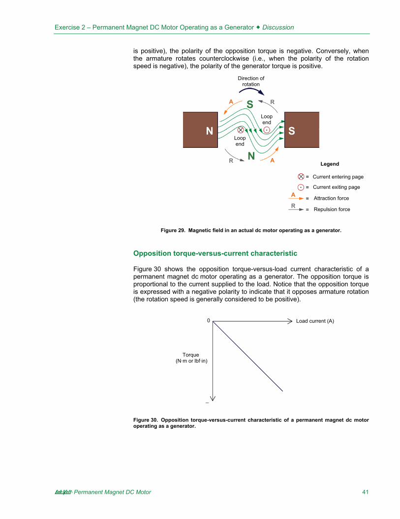
In Figure 28, the magnetic fields produced by the wire loop and the permanent magnets are shown as two separate fields to make the explanation clearer. However, since magnetic lines of force cannot intersect each other, the resulting magnetic field in an actual dc motor operating as a generator resembles that shown in the cross-sectional view of the motor in Figure 29. However, this does not change the end result, i.e., the combined effect of the forces of attraction and repulsion result in a torque that opposes rotation (opposition torque).
Since the opposition torque produced by a permanent magnet dc motor operating as a generator acts in the direction opposite to the direction of rotation of the armature, its polarity is opposite to the polarity of the rotation speed. Thus, when the armature rotates clockwise (i.e., when the polarity of the rotation speed
Motor terminals
Load0&
�
Direction of rotation
0
& N
S
Commutator and brushes
Attraction force
Repulsion force
Legend
A
A
R
R
A
R
S N
Exercise 2 – Permanent Magnet DC Motor Operating as a Generator � Discussion
A Permanent Magnet DC Motor 41
is positive), the polarity of the opposition torque is negative. Conversely, when the armature rotates counterclockwise (i.e., when the polarity of the rotation speed is negative), the polarity of the generator torque is positive.
Figure 29. Magnetic field in an actual dc motor operating as a generator.
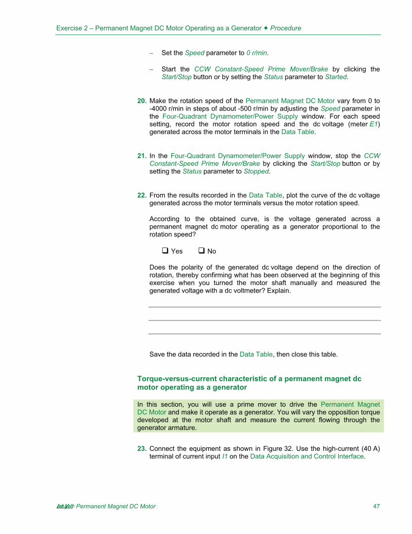
Opposition torque-versus-current characteristic
Figure 30 shows the opposition torque-versus-load current characteristic of a permanent magnet dc motor operating as a generator. The opposition torque is proportional to the current supplied to the load. Notice that the opposition torque is expressed with a negative polarity to indicate that it opposes armature rotation (the rotation speed is generally considered to be positive).
Figure 30. Opposition torque-versus-current characteristic of a permanent magnet dc motor operating as a generator.
Direction of rotation
N
S
Loop end
Loop end
Current entering page
Current exiting page
Legend
Attraction force
Repulsion force
Torque (N·m or lbf·in)
0
&
Load current (A)
A
R
R
A
A
R
S N

Exercise 2 – Permanent Magnet DC Motor Operating as a Generator � Procedure Outline
42 Permanent Magnet DC Motor A
The Procedure is divided into the following sections:
� Electromagnetic induction phenomenon�� Opposition to rotation�� Voltage-versus-speed characteristic of a permanent magnet dc motor
operating as a generator�Clockwise rotation. Counterclockwise rotation.
� Torque-versus-current characteristic of a permanent magnet dc motor operating as a generator�
High voltages are present in this laboratory exercise. Do not make ormodify any banana jack connections with the power on unless otherwisespecified.
Electromagnetic induction phenomenon
In this section of the exercise, you will connect a dc voltmeter across the motor terminals and observe the voltage developed across these terminals when the motor shaft is rotated manually.
1. Place the Permanent Magnet DC Motor on your work surface. Connect a dc voltmeter to the terminals of the Permanent Magnet DC Motor. The red motor terminal is the positive terminal.
2. Make the shaft of the Permanent Magnet DC Motor rotate clockwise with your hands. Notice that a dc voltage of positive polarity appears across the motor terminals. Explain why a dc voltage is developed at the motor terminals when its shaft is rotated.
3. Make the shaft of the Permanent Magnet DC Motor rotate counterclockwise with your hands. Does a dc voltage of negative polarity appear across the motor terminals? Why?
4. Disconnect the dc voltmeter from the Permanent Magnet DC Motor.
PROCEDURE OUTLINE
PROCEDURE

Exercise 2 – Permanent Magnet DC Motor Operating as a Generator � Procedure
A Permanent Magnet DC Motor 43
Opposition to rotation
5. Make the shaft of the Permanent Magnet DC Motor rotate with your hands. Notice that it is easy to make the motor shaft rotate. Explain why.
6. Short-circuit the two terminals of the Permanent Magnet DC Motor with a lead.
Make the motor shaft rotate clockwise with your hands, then make it rotate counterclockwise. Notice that it is less easy to make the motor shaft rotate when the motor terminals are short-circuited. Explain why.
7. Remove the lead short-circuiting the motor terminals.
Voltage-versus-speed characteristic of a permanent magnet dc motor operating as a generator
In this section, you will use a prime mover to drive the Permanent Magnet DC Motor and make it operate as a generator. You will vary the rotation speed of the prime mover by steps and measure the dc voltage generated across the motor terminals.
8. Refer to the Equipment Utilization Chart in Appendix A to obtain the list of equipment required to perform the rest of this exercise.
Install the equipment in the Workstation.
Mechanically couple the Four-Quadrant Dynamometer/Power Supply to the Permanent Magnet DC Motor using a timing belt.
Before coupling rotating machines, make absolutely sure that power isturned off to prevent any machine from starting inadvertently.

Exercise 2 – Permanent Magnet DC Motor Operating as a Generator � Procedure
44 Permanent Magnet DC Motor A
9. Make sure that the main power switch on the Four-Quadrant Dynamometer/ Power Supply is set to the O (off) position, then connect its Power Input to an ac power wall outlet.
Connect the Power Input of the Data Acquisition and Control Interface (DACI) to a 24 V ac power supply. Turn the 24 V ac power supply on.
10. Connect the USB port of the Four-Quadrant Dynamometer/Power Supply to a USB port of the host computer.
Connect the USB port of the Data Acquisition and Control Interface to a USB port of the host computer.
11. On the Four-Quadrant Dynamometer/ Power Supply, set the Operating Mode switch to Dynamometer. This setting allows the Four-Quadrant Dynamometer/Power Supply to operate as a prime mover, a brake, or both, depending on the selected function.
Turn the Four-Quadrant Dynamometer/Power Supply on by setting the main power switch to I (on).
12. Turn the host computer on, then start the LVDAC-EMS software.
In the LVDAC-EMS Start-Up window, make sure that the Data Acquisition and Control Interface and the Four-Quadrant Dynamometer/Power Supply are detected. Make sure that the Computer-Based Instrumentation function for the Data Acquisition and Control Interface is selected. Also, select the network voltage and frequency that correspond to the voltage and frequency of your local ac power network, then click the OK button to close the LVDAC-EMS Start-Up window.
13. Connect the equipment as shown in Figure 31. In this circuit, the Permanent Magnet DC Motor is driven, via a belt, by the motor in the Four-Quadrant Dynamometer/Power Supply. E1 is a voltage input of the Data Acquisition and Control Interface.
a Appendix C shows in more detail the equipment and the connections required for the circuit diagram below.

Exercise 2 – Permanent Magnet DC Motor Operating as a Generator � Procedure
A Permanent Magnet DC Motor 45
Figure 31. Setup used to plot the voltage-versus-speed characteristic of a permanent magnet dc motor operating as a generator.
Clockwise rotation
14. In LVDAC-EMS, open the Four-Quadrant Dynamometer/Power Supply window, then make the following settings:
� Set the Function parameter to CW Constant-Speed Prime Mover/Brake. This setting makes the Four-Quadrant Dynamometer/Power Supply operate as a clockwise prime mover/brake with a speed setting corresponding to the Speed parameter.
� Set the Pulley Ratio parameter to 24:12. The first and second numbers in this parameter specify the number of teeth on the pulley of the Four-Quadrant Dynamometer/Power Supply and the number of teeth on the pulley of the machine under test (i.e., the Permanent Magnet DC Motor), respectively.
� Make sure that the Speed Control parameter is set to Knob. This allows the speed of the clockwise prime mover/brake to be controlled manually.
� Set the Speed parameter (i.e., the speed command) to 1000 r/min by entering 1000 in the field next to this parameter. Notice that the speed command is the targeted speed at the shaft of the machine coupled to the prime mover, i.e., the speed of the Permanent Magnet DC Motor in the present case.
a The speed command can also be set by using the Speed control knob in the Four-Quadrant Dynamometer/Power Supply window.
15. In LVDAC-EMS, start the Metering application. Set meter E1 as a dc voltmeter.
Click the Continuous Refresh button to enable continuous refresh of the values indicated by the various meters in the Metering application.
Constant-speed prime mover
Permanent Magnet
DC Motor

Exercise 2 – Permanent Magnet DC Motor Operating as a Generator � Procedure
46 Permanent Magnet DC Motor A
16. In the Four-Quadrant Dynamometer/Power Supply window, start the CW Constant-Speed Prime Mover/Brake by clicking the Start/Stop button or by setting the Status parameter to Started.
Observe that the prime mover starts to rotate, thereby driving the shaft of the Permanent Magnet DC Motor.
The Speed meter in the Four-Quadrant Dynamometer/Power Supply window indicates the rotation speed of the Permanent Magnet DC Motor. Is this speed approximately equal to the value of the Speed parameter (1000 r/min)?
� Yes � No
Meter E1 in the Metering window indicates the dc voltage generated across the Permanent Magnet DC Motor terminals. Record this voltage below.
DC voltage generated � V
17. In LVDAC-EMS, open the Data Table window. Set the Data Table to record the rotation speed of the Permanent Magnet DC Motor (indicated by the Speed meter in the Four-Quadrant Dynamometer/Power Supply) and the dc voltage generated across the motor terminals (indicated by meter E1 in the Metering window).
a To select the parameters to be recorded in the Data Table, click the Options menu of the Data Table and then click Record Settings… In the Settings list, select Four-Quadrant Dynamometer/Power Supply, then check the Speed box. In the Settings list, select Metering, then check the box of meter E1. Click OK to close the Record Settings box.
18. Make the rotation speed of the Permanent Magnet DC Motor vary from 0 to 4000 r/min in steps of 500 r/min by adjusting the Speed parameter. For each speed setting, record the motor rotation speed (indicated by the Speed meter) and the dc voltage (meter E1) generated across the motor terminals in the Data Table by clicking the Record Data button in this table.
Counterclockwise rotation
19. In the Four-Quadrant Dynamometer/Power Supply window, stop the CW Constant-Speed Prime Mover/Brake by clicking the Start/Stop button or by setting the Status parameter to Stopped. Then, make the following settings:
� Set the Function parameter to CCW Constant-Speed Prime Mover/Brake. This setting makes the Four-Quadrant Dynamometer/Power Supply operate as a counterclockwise prime mover/brake with a speed setting corresponding to the Speed parameter.
� Set the Pulley Ratio parameter to 24:12.
� Make sure that the Speed Control parameter is set to Knob.
Exercise 2 – Permanent Magnet DC Motor Operating as a Generator � Procedure
A Permanent Magnet DC Motor 47
� Set the Speed parameter to 0 r/min.
� Start the CCW Constant-Speed Prime Mover/Brake by clicking the Start/Stop button or by setting the Status parameter to Started.
20. Make the rotation speed of the Permanent Magnet DC Motor vary from 0 to -4000 r/min in steps of about -500 r/min by adjusting the Speed parameter in the Four-Quadrant Dynamometer/Power Supply window. For each speed setting, record the motor rotation speed and the dc voltage (meter E1) generated across the motor terminals in the Data Table.
21. In the Four-Quadrant Dynamometer/Power Supply window, stop the CCW Constant-Speed Prime Mover/Brake by clicking the Start/Stop button or by setting the Status parameter to Stopped.
22. From the results recorded in the Data Table, plot the curve of the dc voltage generated across the motor terminals versus the motor rotation speed.
According to the obtained curve, is the voltage generated across a permanent magnet dc motor operating as a generator proportional to the rotation speed?
� Yes � No
Does the polarity of the generated dc voltage depend on the direction of rotation, thereby confirming what has been observed at the beginning of this exercise when you turned the motor shaft manually and measured the generated voltage with a dc voltmeter? Explain.
Save the data recorded in the Data Table, then close this table.
Torque-versus-current characteristic of a permanent magnet dc motor operating as a generator
In this section, you will use a prime mover to drive the Permanent Magnet DC Motor and make it operate as a generator. You will vary the opposition torque developed at the motor shaft and measure the current flowing through the generator armature.
23. Connect the equipment as shown in Figure 32. Use the high-current (40 A) terminal of current input I1 on the Data Acquisition and Control Interface.

Exercise 2 – Permanent Magnet DC Motor Operating as a Generator � Procedure
48 Permanent Magnet DC Motor A
In the Data Acquisition and Control Settings window of LVDAC-EMS, set the Range of current input I1 to High.
a Appendix C shows in more detail the equipment and the connections required for the circuit diagram.
Figure 32. Setup used to plot the torque-versus-current characteristic of a permanent magnet dc motor operating as a generator.
24. In the Four-Quadrant Dynamometer/Power Supply window, make the following settings:
� Set the Function parameter to Positive Constant-Torque Prime Mover/Brake. This setting makes the Four-Quadrant Dynamometer/Power Supply operate as a constant-torque prime mover/brake with a torque setting corresponding to the Torque parameter.
� Set the Pulley Ratio parameter to 24:12.
� Set the Torque parameter to 0.3 N·m (2.7 lbf in) by entering 0.3 (2.7) in the field next to this parameter.
25. In the Metering window of LVDAC-EMS, set meter I1 to display dc values. Ensure the continuous refresh mode of the meters is enabled.
26. In the Four-Quadrant Dynamometer/Power Supply window, start the Positive Constant-Torque Prime Mover/Brake by setting the Status parameter to Started or by clicking the Start/Stop button.
Observe that the prime mover starts to rotate clockwise, thereby driving the shaft of the Permanent Magnet DC Motor.
The Speed and Torque meters in the Four-Quadrant Dynamometer/Power Supply indicate the rotation speed and torque at the shaft of the Permanent Magnet DC Motor. Notice that the torque is of negative polarity, i.e., opposite to the polarity (positive) of the rotation speed. This is because the Permanent Magnet DC Motor is operating as a generator. Is the torque (absolute value)
Permanent Magnet
DC Motor High-current
range Constant-torque
prime mover

Exercise 2 – Permanent Magnet DC Motor Operating as a Generator � Procedure
A Permanent Magnet DC Motor 49
indicated by the Torque meter approximately equal to the value of the Torque parameter?
� Yes � No
Meter I1 in the Metering window indicates the dc current flowing in the armature of the Permanent Magnet DC Motor. Record this current below.
DC current flowing in the motor � A
27. In LVDAC-EMS, open the Data Table and make the settings required to record the torque developed the shaft of this motor (indicated by the Torque meter in the Four-Quadrant Dynamometer/Power Supply) and the dc current flowing in the armature of the Permanent Magnet DC Motor (indicated by meter I1 in the Metering window).
a To select the parameters to be recorded in the Data Table, click the Options menu of the Data Table and then click Record Settings… In the Settings list, select Four-Quadrant Dynamometer/Power Supply, then check the Torque box. In the Settings list, select Metering, then check the box of meter I1. Click OK to close the Record Settings box.
28. Make the torque developed at the shaft of the Permanent Magnet DC Motor vary from 0 to -0.7 N·m (or from 0 to -6.0 lbf·in) in steps of -0.1 N·m (or -1 lbf·in) by adjusting the Torque parameter. For each torque setting, record the current flowing in the armature of the dc motor (meter I1) and the torque developed at the motor shaft (indicated by the Torque meter) in the Data Table.
Since the output of the Permanent Magnet DC Motor is short circuited by current input I1, high currents can flow in the motor at low torques and rotation speeds. Make sure not to exceed the current rating of the Permanent Magnet DC Motor.Perform the remainder of this manipulation in less than 5 minutes.
29. In the Four-Quadrant Dynamometer/Power Supply window, stop the Positive Constant-Torque Prime Mover/Brake.
30. From the results recorded in the Data Table, plot a curve of the torque developed at the motor shaft as a function of the current flowing in the armature of the dc motor.
According to the obtained curve, is the torque developed at the shaft of a permanent magnet dc motor operating as a generator proportional to the current flowing in the motor armature?
� Yes � No

Exercise 2 – Permanent Magnet DC Motor Operating as a Generator � Conclusion
50 Permanent Magnet DC Motor A
31. Save the data recorded in the Data Table, then close this table. Turn the Four-Quadrant Dynamometer/Power Supply off by setting the main power switch to O (off). Close the LVDAC-EMS software. Disconnect all leads and return them to their storage location.
In this exercise, you familiarized yourself with a permanent magnet dc motor. You learned that this motor consists of a rotor (armature) made of several loops of wire, and a stator made of permanent magnets that produce a fixed magnetic field. When the rotor is rotated by a prime mover, it cuts the lines of force of the stator magnetic field, which produces a dc voltage across the motor terminals: the dc motor operates as a dc generator. The magnitude of the generated voltage is proportional to the rotation speed, while the polarity of this voltage depends on the direction of rotation. For instance, when the rotor rotates clockwise, the dc voltage is positive, and vice-versa. You learned that when a load is connected across the motor terminals, a force (torque) opposing rotor rotation is produced. This torque is in the direction opposite to the direction of rotation. The higher the current supplied to the load, the stronger the torque opposing rotation.
1. By referring to Figure 21, describe the construction of a simple permanent magnet dc motor.
2. By referring to Figure 24, describe the operation of a simple permanent magnet dc motor used as a generator. Explain how an alternating-current (ac) voltage is induced across the armature wire loop, and why this voltage is unipolar (i.e., why it always has the same polarity) at the motor terminals.
CONCLUSION
REVIEW QUESTIONS

Exercise 2 – Permanent Magnet DC Motor Operating as a Generator � Review Questions
A Permanent Magnet DC Motor 51
3. What effect does increasing the number of wire loops and commutator segments have on the voltage generated by a permanent magnet dc motor operating as a generator? Explain.
4. Describe the relationship between the voltage generated by a dc motor operating as a generator as a function of the armature rotation speed. When is the generated voltage of positive polarity? When is this voltage of negative polarity?
5. Explain why a force (torque) opposes the rotation of a dc motor operating as a generator when an electrical load like a resistor is connected to the dc motor terminals. When is this force of positive polarity? When is this force of negative polarity?


Sample
Extracted from
Instructor Guide


Exercise 2 Permanent Magnet DC Motor Operating as a Generator
4 Permanent Magnet DC Motor A
Exercise 2 Permanent Magnet DC Motor Operating as a Generator
2. When the motor shaft is rotated, the armature wire loops cut the magnetic field produced by the stator permanent magnets, causing a voltage to be induced across the wire loop terminals. This voltage is collected by the commutator segments and delivered to stationary brushes connected to the motor terminals.
3. Yes. When the direction of rotation of the motor shaft is reversed, the polarity of the dc voltage at the motor terminals also reverses.
5. When no load is connected to the terminals of the Permanent Magnet DC Motor, no current flows in the armature wire loops, and thus, no magnetic field is produced in the wire loops. Therefore, no force (torque) opposes the rotation of the motor shaft.
6. When a load (in the present case, a short circuit) is connected to the terminals of the Permanent Magnet DC Motor, current starts to flow in the armature wire loops through the load. This current produces a magnetic field inside each of the wire loops. The location of the poles of the magnetic field produced by the wire loops with respect to the poles of the permanent magnets on the motor stator creates forces of attraction and repulsion. The combined effect of these forces is to apply torque to the motor shaft that opposes rotation.
16. Yes.
The dc voltage generated is about 11 V.
ANSWERS TO PROCEDURE STEP QUESTIONS

Exercise 2 Permanent Magnet DC Motor Operating as a Generator
A Permanent Magnet DC Motor 5
18. Voltage generated across the terminals of the Permanent Magnet DC Motor as a function of the rotation speed.
Clockwise rotation Counterclockwise rotation
Motor rotation speed (r/min)
Generated dc voltage (V)
Motor rotation speed (r/min)
Generated dc voltage (V)
0 0.0 0.0 0.0
500 5.7 -500 -5.9
1000 11.5 -1000 -11.8
1500 17.3 -1500 -17.6
2000 23.1 -2000 -23.3
2500 29.0 -2500 -29.1
3000 34.8 -3000 -34.9
3500 40.6 -3500 -40.7
4000 46.3 -4000 -46.4
22.
Voltage generated across the terminals of the Permanent Magnet DC Motor as a function of the rotation speed.
-50
-40
-30
-20
-10
0
10
20
30
40
50
-4000 -3000 -2000 -1000 0 1000 2000 3000 4000
Motor rotation speed (r/min)
Gen
erat
ed d
c vo
ltage
(V)

Exercise 2 Permanent Magnet DC Motor Operating as a Generator
6 Permanent Magnet DC Motor A
Yes. When the motor rotates in the clockwise direction, the dc voltage generated across the motor terminals is of positive polarity. Conversely, when the motor rotates in the counterclockwise direction, the dc voltage generated across the motor terminals is of negative polarity.
26. Yes. DC current flowing in the motor 2 2.8 A
28. Torque developed at the motor shaft as a function of the current flowing in the armature of the dc motor.
Current flowing in the armature of the dc motor (A) Torque developed at the motor shaft
0.0 0.0 N·m 0.0 lbf·in
0.8 -0.1 N·m -0.9 lbf·in
1.8 -0.2 N·m -1.8 lbf·in
2.8 -0.3 N·m -2.6 lbf·in
3.8 -0.4 N·m -3.5 lbf·in
4.8 -0.5 N·m -4.4 lbf·in
5.8 -0.6 N·m -5.3 lbf·in
6.8 -0.7 N·m -6.2 lbf·in
30. Yes
Torque developed at the shaft of the Permanent Magnet DC Motor (clockwise direction of rotation) as a function of the armature current flowing in the motor.
-0.7
-0.6
-0.5
-0.4
-0.3
-0.2
-0.1
0.00.0 1.0 2.0 3.0 4.0 5.0 6.0 7.0
Current flowing in the motor (A)
Torq
ue d
evel
oped
at t
he m
otor
sha
ft (N
·m)
Torq
ue d
evel
oped
at t
he m
otor
sha
ft (lb
f·in)
0.0
-0.9
-1.8
-2.6
-3.5
-4.4
-5.3
-6.2

Exercise 2 Permanent Magnet DC Motor Operating as a Generator
A Permanent Magnet DC Motor 7
1. The stator is the fixed part of the motor in which the rotor turns. The stator consists of permanent magnets aligned so that poles of opposite polarities face each other. Therefore, lines of magnetic field pass from one permanent magnet to the other through the metallic armature. The rotor is the rotating part of the motor. It consists of a wire loop mounted on a rotary metallic armature. The ends of the wire loop are connected to terminals on the dc motor, via a commutator and a pair of brushes (usually made of carbon). The commutator has two segments isolated from one another. Each segment is connected to one terminal of the wire loop.
2. When the armature wire loop is rotated within the magnetic field of the magnets, it cuts the lines of magnetic field and a voltage is induced across the loop terminals. This voltage is collected by the two commutator segments and delivered to stationary brushes connected to the motor terminals. The polarity of the voltage across the wire loop (voltage across the commutator segments) continually alternates: it is positive for half a turn, then negative for the next half turn, and so on. Because of this, the voltage across the wire loop is an alternating-current (ac) voltage. However, the voltage at the motor terminals (voltage across the brushes) is unipolar (i.e., it always has the same polarity) because the commutator reverses the connections between the loop terminals and motor terminals each time the two slots of the commutator pass by the stationary brushes (i.e., twice per rotation at the exact instant when the polarity of the voltage across the wire loop reverses).
3. Increasing the number of wire loops and commutator segments reduces the fluctuation of the voltage generated at the dc motor terminals. This is because a higher number of wire loops and commutator segments provides a higher number of pulses per rotation in the voltage at the dc motor terminals.
4. The voltage generated by a dc motor operating as a generator is proportional to the armature rotation speed. Thus, the higher the armature rotation speed, the higher the generated voltage.
The polarity of the generated voltage depends on the direction of rotation of the armature. In general, when the armature rotates in the clockwise (CW) direction, the generated voltage is considered to be positive. Conversely, when the armature rotates in the counterclockwise (CCW) direction, the generated voltage is considered to be negative.
5. When an electrical load like a resistor is connected to a dc motor operating as a generator, currents flow in the armature wire loops and magnetic field is produced in each of these loops. The location of the poles of the magnetic field produced in the loops with respect to the poles of the stator permanent magnets creates forces of attraction and repulsion. The combined effect of these forces is a torque that opposes rotation of the motor shaft.
ANSWERS TO REVIEW QUESTIONS

Exercise 2 Permanent Magnet DC Motor Operating as a Generator
8 Permanent Magnet DC Motor A
Since the opposition torque is in a direction opposite to the direction of rotation of the armature, its polarity is opposite to the polarity of the rotation speed. Thus, when the armature rotates clockwise (i.e., when the polarity of the rotation speed is positive), the polarity of the opposition torque is negative. Conversely, when the armature rotates counterclockwise (i.e., when the polarity of the rotation speed is negative), the polarity of the generator torque is positive.


A Permanent Magnet DC Motor 85
Bibliography
Wildi, Theodore, Electrical Machines, Drives, and Power Systems, 2nd edition, New Jersey, Prentice Hall, 1991. ISBN 0-13-251547-4.
