dc brushless (pbl) dc permanent magnet (pm) ac induction … · 2016-10-16 · dc brushless (pbl)...
TRANSCRIPT

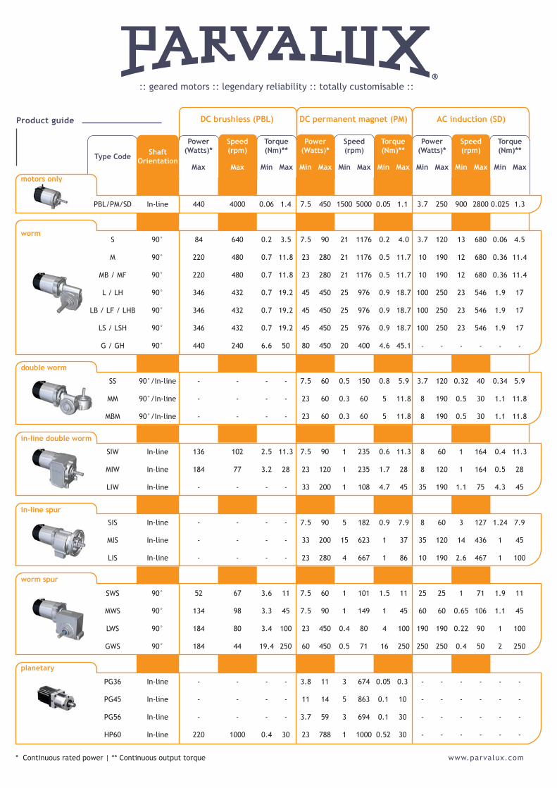
* Continuous rated power | ** Continuous output torque
:: geared motors :: legendary reliability :: totally customisable ::
DC brushless (PBL) DC permanent magnet (PM) AC induction (SD)
motors only
double worm
in-line double worm
in-line spur
worm spur
planetary
worm
Type Code ShaftOrientation
Power (Watts)*
Speed(rpm)
Torque (Nm)**
Power (Watts)*
Speed(rpm)
Torque (Nm)**
Power (Watts)*
Speed(rpm)
Torque (Nm)**
Max Max Min Max Min Max Min Max Min Max Min Max Min Max Min Max
PBL/PM/SD In-line 440 4000 0.06 1.4 7.5 450 1500 5000 0.05 1.1 3.7 250 900 2800 0.025 1.3
S 90° 84 640 0.2 3.5 7.5 90 21 1176 0.2 4.0 3.7 120 13 680 0.06 4.5
M 90° 220 480 0.7 11.8 23 280 21 1176 0.5 11.7 10 190 12 680 0.36 11.4
MB / MF 90° 220 480 0.7 11.8 23 280 21 1176 0.5 11.7 10 190 12 680 0.36 11.4
L / LH 90° 346 432 0.7 19.2 45 450 25 976 0.9 18.7 100 250 23 546 1.9 17
LB / LF / LHB 90° 346 432 0.7 19.2 45 450 25 976 0.9 18.7 100 250 23 546 1.9 17
LS / LSH 90° 346 432 0.7 19.2 45 450 25 976 0.9 18.7 100 250 23 546 1.9 17
G / GH 90° 440 240 6.6 50 80 450 20 400 4.6 45.1 - - - - - -
SS 90°/In-line - - - - 7.5 60 0.5 150 0.8 5.9 3.7 120 0.32 40 0.34 5.9
MM 90°/In-line - - - - 23 60 0.3 60 5 11.8 8 190 0.5 30 1.1 11.8
MBM 90°/In-line - - - - 23 60 0.3 60 5 11.8 8 190 0.5 30 1.1 11.8
SIW In-line 136 102 2.5 11.3 7.5 90 1 235 0.6 11.3 8 60 1 164 0.4 11.3
MIW In-line 184 77 3.2 28 23 120 1 235 1.7 28 8 120 1 164 0.5 28
LIW In-line - - - - 33 200 1 108 4.7 45 35 190 1.1 75 4.3 45
SIS In-line - - - - 7.5 90 5 182 0.9 7.9 8 60 3 127 1.24 7.9
MIS In-line - - - - 33 200 15 623 1 37 35 120 14 436 1 45
LIS In-line - - - - 23 280 4 667 1 86 10 190 2.6 467 1 100
SWS 90° 52 67 3.6 11 7.5 60 1 101 1.5 11 25 25 1 71 1.9 11
MWS 90° 134 98 3.3 45 7.5 90 1 149 1 45 60 60 0.65 106 1.1 45
LWS 90° 184 80 3.4 100 23 450 0.4 80 4 100 190 190 0.22 90 1 100
GWS 90° 184 44 19.4 250 60 450 0.5 71 16 250 250 250 0.4 50 2 250
PG36 In-line - - - - 3.8 11 3 674 0.05 0.3 - - - - - -
PG45 In-line - - - - 11 14 5 863 0.1 10 - - - - - -
PG56 In-line - - - - 3.7 59 3 694 0.1 30 - - - - - -
HP60 In-line 220 1000 0.4 30 23 788 1 1000 0.52 30 - - - - - -
Product guide
www.parvalux.com
Gearb
ox typ
e
Gearb
ox typ
e
Gearb
ox typ
e
Perfo
rman
ce
In
ductio
n
Perfo
rman
ce
In
ductio
n
Perfo
rman
ce
In
ductio
n
Dimen
sions
In
ductio
n
Dimen
sions
In
ductio
n
Perfo
rman
ce
Com
muta
tor
Perfo
rman
ce
Com
muta
tor
Dimen
sions
Com
muta
tor
Dimen
sions
Com
muta
tor
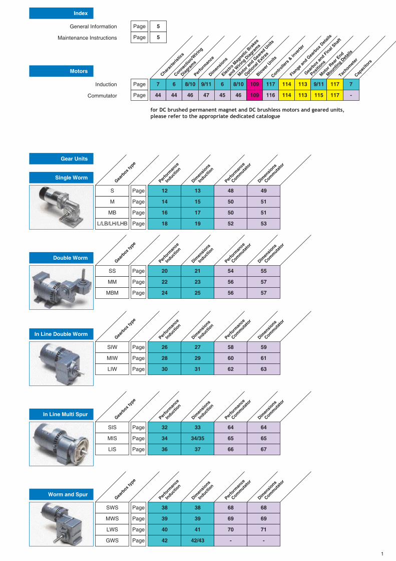
Index
Motors
Gear Units
Single Worm
Double Worm
In Line Double Worm
General Information
Maintenance Instructions
Induction
Commutator
Page
Page
S
SS
SIW
Page
Page
Page
12 13 48 49
15 50 51
17 50 51
19 52 53
20 21 54 55
26 27 58 59
14
22 23 56 57
28 29 60 61
16
24 25 56 57
18
Dimen
sions
In
ductio
n
Perfo
rman
ce
Com
muta
tor
Dimen
sions
Com
muta
tor
Page
Page
Page
Page
Page
Page
M
MM
MIW
30 31 62 63PageLIW
MB
MBM
L/LB/LH/LHB
5
Page
Page
5
Charac
teris
tics
Connectio
n/Wiri
ng
Diag
ram
s
Perfo
rman
ce
Dimen
sions
Electro
Mag
netic
Brake
s
an
d Wiri
ng Diag
ram
s
Motor a
nd Gea
red U
nits
Optio
nal Ext
ras
Blower
Units
Controlle
rs &
inve
rter
Flange a
nd Gea
rbox D
etail
s
Gearb
ox and F
inal
Shaft
Posit
ions
Motor R
ear E
nd
Mountin
g Det
ails
Tachom
eter
Capac
itors
7 6 8/10 9/11 6 8/10 109 117 114 113 9/11 117 7
44 44 46 47 45 46 109 116 114 113 115 117 -
Gearb
ox typ
e
Perfo
rman
ce
In
ductio
n
Dimen
sions
In
ductio
n
Perfo
rman
ce
Com
muta
tor
Dimen
sions
Com
muta
tor
In Line Multi Spur
SIS Page 32 33 64 64
34
36
34/35
37
65
66
65
67
Page
Page
MIS
LIS
Gearb
ox typ
e
Perfo
rman
ce
In
ductio
n
Dimen
sions
In
ductio
n
Perfo
rman
ce
Com
muta
tor
Dimen
sions
Com
muta
tor
Worm and Spur
SWS Page 38
39
38 68 68
MWS
LWS
GWS
Page
Page
Page
40
42
39
41
42/43
69
70
-
69
71
-
1
for DC brushed permanent magnet and DC brushless motors and geared units, please refer to the appropriate dedicated catalogue
Terms and Conditions of Sale
Whilst Parvalux takes all reasonably practicable steps to design and manufacture its products to comply with the requirements of the Health andSafety at Work Act 1974, all products must be properly used and Purchasers are reminded that their obligations under the Act are to ensure thatthe installation and operation of such products at a place of work should be safe and without risk to health.
Contracts and orders are accepted subject to these conditions of sale. Unless expressly accepted inwriting any qualification of these conditions contained in any document of the Buyer shall be deemed tobe inapplicable.
Unless otherwise stated all orders are accepted on condition any fluctuation in cost of materials and/orwages will entail a corresponding adjustment to the quoted price.
We reserve the right to consider quotations invalid 14 days after issue.
All orders (which must be in writing) to be accompanied by sufficient information enabling us to proceedwith the order forthwith, otherwise we shall be at liberty to amend the delivery and/or offer price.
Once an order has been accepted by us it may not be cancelled or varied except with our consent, whichat our discretion may be given only on terms which will indemnify us against any expense which shallinclude all our proper charges for work carried out and goods wholly or partly manufactured prior to thedate of such cancellation or variation:If, owing to war, strikes, difficulty in obtaining materials or causes of any nature beyond our control we areunable to deliver any part of an order, we shall have the right (on giving notice in writing) to cancel theundelivered balance of the order and the customer shall not have any claim for or arising out of suchinability, delay or cancellation.
Goods supplied in accordance with customers orders cannot be accepted for return without our writtenconsent; if approval is given a handling charge will be made. Returned goods must be consigned carriagepaid.
Subject to a minimum annual turnover our terms are strictly Nett Monthly Account, initial orders should beaccompanied by a Bankers and two Trade References.Small value orders will be accepted on a cash with order basis or credit card details.
The time given for delivery ex works is estimated only and not in any way guaranteed. Every endeavourwill be made to meet the delivery given in good faith. We cannot however accept liability for failure to doso. When reduction in the scheduled rate of delivery is requested and agreed by us we reserve the rightto make and shall be entitled to all additional charges incurred .
Prices include delivery to U.K. mainland destinations, mode of transport at our discretion. When deliveryis by a specific carrier at purchaser’s request the carriage will be charged as an extra.
We undertake to give separate postal notification on the day of despatch. Claims for non-delivery will notbe entertained unless the carriers and ourselves are notified within 14 days from despatch date or 5 daysin the case of postal or passenger train delivery services. Furthermore, we are unable to acceptresponsibility for damage, shortage or incorrect goods supplied, unless the carriers and ourselves arenotified within 3 days from receipt.
Our products are guaranteed for a period of 24 months from date of invoice against electrical breakdownor mechanical failure resulting from defective materials and/or workmanship providing the breakdown orfailure is not due to misuse or operation under adverse conditions (including use with non Parvaluxapproved controllers). Any unit proving faulty and covered by the provisions of this guarantee must bereturned to our works complete, carriage paid, for examination when it will be repaired or replaced at ouroption. Units that have been dismantled, carbon brushes, capacitors and flexible cables are exceptedfrom this guarantee. Mutilation or removal of the nameplate will invalidate the guarantee.
Every endeavour will be made to supply goods free from defects, we cannot accept any responsibility orentertain claims for consequential damages or expenses.
The Buyer will indemnify us against damages, penalties, costs and expenses to which we may becomeliable as a result of work done in accordance with the Buyer’s specification which involves an infringementof any letters, patents, or registered design.
All drawings issued by us remain our property and must be returned on request. These must not beloaned, reproduced, copied or in any way altered wholly or in part without our written authority nor mayinformation injurious to us be furnished from them.
All tools, dies, moulds, jigs and fixtures, etc., will remain our property whether or not a charge is madetowards their cost.
Our products are carefully inspected and submitted to our standard tests at our works before despatch. Iftests other than these are specified, or tests in the presence of you or your representative are required,these will be charged for. In the event of any delay on your part in attending such tests after 7 days’ noticethat we are ready, the tests will proceed in your absence and shall be deemed to have been made in yourpresence.
Unless otherwise agreed in writing the contract shall in all respects be constructed and operate as anEnglish contract and in conformity with English law.
It is our policy to continuously develop and improve our products. We therefore reserve the rightto modify or change our designs at our convenience and without prior notice.
1 General
2 Variation in price
3 Quotations
4 Acceptance
5 Cancellation andvariation
6 Returns
7 Terms
8 Delivery
9 Carriage
10 Damageshortage andnon-delivery
11 Warranty
12 Consequentialdamage
13 Indemnity
14 Drawings
15 Tools
16 Inspection andtests
17 Legalconstruction
18 Policy
2
Some of your questions
answered!
Which motors/gearmotors are electricallyreversible?
All motors and gearmotors shown in this catalogue are reversible.
(except shaded pole). Some require a full stop before reversing.
Can continuous duty motors/gearmotors be usedintermittently?
All rated torques shown in this catalogue are for continuous
operation. Continuous duty products can be used intermittently.
Operation at loads higher than nameplate ratings is possible for short
periods as long as there are rest periods for cooling. Loads must not
exceed the mechanical rating for the gears (see page 5) without
consulting our sales engineers. The temperature of the motor should
be monitored during testing to make sure it is not overheating.
Can single speed motors and gearmotors ever beoperated as variable speed?
Three phase and some Permanent Split Capacitor designs may be
operated as variable speed with a frequency inverter. Commutator
motors can be operated as variable speed using a thyristor controller.
Is an adjustable speed system ever appropriatefor a single speed application?
Adjustable speed systems are sometimes appropriate for single
speed applications. If the desired speed is not known or not offered in
a single speed product, an adjustable speed system may be set to
the desired speed.
What is IP 54?
The IP number is an international system for rating enclosures.
An IP 54 is for protection against dust and splashing liquids.
What is meant by the term self locking?
Self locking refers to the tendency of some gearing to resist
movement when the gearmotor is at rest and the load is attempting to
move. An example is a load on a conveyer belt trying to drive the
system backwards.
Which gearheads are self locking?
Parallel shaft gearheads and right angle gearheads with low ratios
are generally not considered to be “Self locking”. Right angle
gearheads with ratios greater than 25:1 are often considered to be
“Self locking”. They will resist movement up to their torque rating. As
the gearing nears the end of its useful life or if it is subjected to
overload conditions, it may wear to the point where it is no longer
“Self locking”. Self locking gearing is not a recommended method for
preventing movement in applications where this movement may
cause injury or damage. An external brake is recommended for those
applications. (see pages 6, 45 and 72)
AQ
AQ
AQ
A
Q
A
Q
A
Q
A
Q Can more than one motor be operated from asingle control?
Operation of more than one motor from a single control is not
normally recommended. However, when cost is a primary concern, a
multiple motor/single control system with either permanent magnet
motors and control, or 3 phase motors and control may be
successfully implemented. More than one permanent magnet motor
may be operated with a single permanent magnet control as long as
the sum of the motor currents does not exceed the rated output
current of the controller. Comprehensive testing is recommended
because this type of system may produce fluctuation or drifting speed
output. More than one 3 phase motor may be operated with a single
3 phase control. Motor speeds should not fluctuate as long as the
motors are not overloaded and the sum of the motor currents does
not exceed the rated output current of the control.
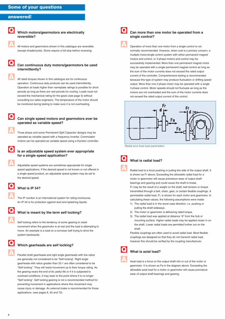
What is radial load?
Radial load is a force pushing or pulling the side of the output shaft. It
is shown as Fr above. Exceeding the allowable radial load for a
motor or gearmotor will cause premature wear of output shaft
bearings and gearing and could cause the shaft to break.
Fr may be the result of a weight on the shaft, belt tension or torque
transmitted through a belt, chain, gear, or certain flexible couplings. A
permissible radial load, Fr, is shown for each motor and gearmotor. In
calculating these values, the following assumptions were made:
1) The radial load is in the worst case direction, i.e. pushing or
pulling the shaft sideways.
2) The motor or gearmotor is delivering rated torque.
3) The radial load was applied at distance “d” from the hub or
mounting surface. Higher radial loads may be applied closer in on
the shaft. Lower radial loads are permitted further out on the
shaft.
Flexible couplings are often used to avoid radial load. Most flexible
couplings are designed so that they do not transmit radial load,
however this should be verified by the coupling manufacturer.
What is axial load?
Axial load is a force on the output shaft into or out of the motor or
gearmotor. It is shown as Fa in the diagram above. Exceeding the
allowable axial load for a motor or gearmotor will cause premature
wear of output shaft bearings and gearing.
AQ
AQ
A
Q
Radial and Axial load parameters
4
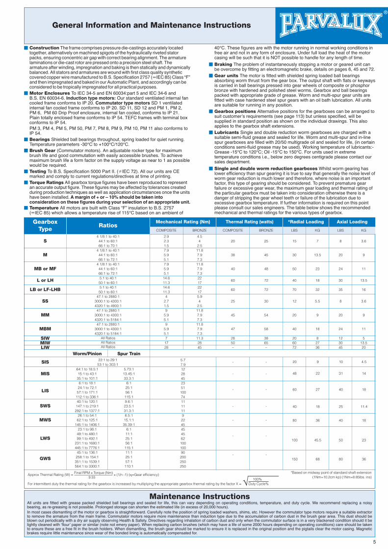
General Information and Maintenance Instructions
� Construction The frame comprises pressure die-castings accurately locatedtogether, alternatively on machined spigots of the hydraulically riveted statorpacks, ensuring concentric air gap with correct bearing alignment. The armaturelaminations or die-cast rotor are pressed onto a precision steel shaft. Thearmature after winding, impregnation and baking is then statically and dynamicallybalanced. All stators and armatures are wound with first class quality syntheticcovered copper wire manufactured to B.S. Specification 2757 (�IEC 85) Class “F”and then impregnated and baked in our Automatic Plant, and accordingly can beconsidered to be tropically impregnated for all practical purposes.
� Motor Enclosures To IEC 34-5 and EN 60034:part 5 and IEC 34-6 andB.S. EN 60034-6. Induction type motors: Our standard ventilated internal fancooled frame conforms to IP 20. Commutator type motors SD 1 ventilatedinternal fan cooled frame conforms to IP 20. SD 11, SD 12 and PM 1, PM 2,PM 6, PM 60 Drip Proof enclosure, internal fan cooled, conforms to IP 21.Plain totally enclosed frame conforms to IP 54. TEFC frames with terminal boxconforms to IP 54.PM 3, PM 4, PM 5, PM 50, PM 7, PM 8, PM 9, PM 10, PM 11 also conforms toIP 54.
� Bearings Shielded ball bearings throughout, spring loaded for quiet running.Temperature parameters -30°C to +100°C/120°C.
� Brush Gear (Commutator motors). An adjustable rocker type for maximumbrush life and good commutation with easily accessible brushes. To achievemaximum brush life a form factor on the supply voltage as near to 1 as possiblewould be required.
� Testing To B.S. Specification 5000 Part II. (�IEC 72). All our units are CEmarked and comply to current regulations/directives at time of printing.
� Torque Ratings All gearbox torque figures have been reproduced to representan accurate output figure. These figures may be affected by tolerances createdduring production techniques as well as application circumstances once the unitshave been installed. A margin of + or – 10% should be taken intoconsideration on these figures during your selection of an appropriate unit.
� Temperature All motors are built with Class “F” insulation to B.S. 2757(�IEC 85) which allows a temperature rise of 115°C based on an ambient of
40°C. These figures are with the motor running in normal working conditions infree air and not in any form of enclosure. Under full load the heat of the motorcasing will be such that it is NOT possible to handle for any length of time.
� Braking The problem of instantaneously stopping a motor or geared unit canbe overcome by fitting an electromagnetic brake, details on pages 6, 45 and 72.
� Gear units The motor is fitted with shielded spring loaded ball bearingsabsorbing worm thrust from the gear box. The output shaft with flats or keywaysis carried in ball bearings pressed into gear wheels of composite or phosphorbronze with hardened and polished steel worms. Gearbox and ball bearingspacked with appropriate grade of grease. Worm and multi-spur gear units arefitted with case hardened steel spur gears with an oil bath lubrication. All unitsare suitable for running in any position.
� Gearbox positions Alternative positions for the gearboxes can be arranged tosuit customer’s requirements (see page 113) but unless specified, will besupplied in standard position as shown on the individual drawings. This alsoapplies to the gearbox shaft extensions.
� Lubricants Single and double reduction worm gearboxes are charged with asuitable semi-fluid grease and sealed for life. Worm and multi-spur and in-linespur gearboxes are filled with 20/50 multigrade oil and sealed for life, (in certainconditions semi-fluid grease may be used). Working temperature of lubricants:-Grease -15°C to 120°C; Oil -15°C to 150°C. For units used in extremetemperature conditions i.e., below zero degrees centigrade please contact oursales department.
� Single and double worm reduction gearboxes Whilst worm gearing haslower efficiency than spur gearing it is true to say that generally the noise level ofworm gear reduction is much lower and therefore, where noise is an importantfactor, this type of gearing should be considered. To prevent premature gearfailure or excessive gear wear, the maximum gear loading and thermal rating ofthe particular gearbox must be taken into consideration otherwise there is adanger of stripping the gear wheel teeth or failure of the lubrication due toexcessive gearbox temperature. If further information is required on this pointplease consult our sales engineers. The table below shows the recommendedmechanical and thermal ratings for the various types of gearbox.
Maintenance InstructionsAll units are fitted with grease packed shielded ball bearings and sealed for life, this can vary depending on operating conditions, temperature, and duty cycle. We recommend replacing a noisybearing, as re-greasing is not possible. Prolonged storage can shorten the estimated life (in excess of 20,000 hours).In most cases dismantling of the motor or gearbox is straightforward. Carefully note the position of spring loaded washers, shims, etc. However the commutator type motors require a suitable extractorto remove the armature from the main frame. Commutator motors require more maintenance than induction type due to the accumulation of carbon dust in the brush gear area. This dust should beblown out periodically with a dry air supply observing Health & Safety. Directives regarding inhalation of carbon dust and only when the commutator surface is in a very blackened condition should it belightly cleaned with ‘flour’ paper or similar (note not emery paper). When replacing carbon brushes (which may have a life of some 2000 hours depending on operating conditions) care should be takento ensure these are a free fit in the brush holders. When dismantling, the brush gear should be marked to ensure it is replaced in the original position and the pigtails clear the motor casing. Magneticbrakes require little maintenance since wear of the bonded lining is automatically compensated for.
Approx Thermal Rating (W) = Final RPM × Torque (Nm) × (1/n -1) (η=Gear efficiency)9.55 100%
For intermittent duty the thermal rating for the gearbox is increased by multiplying the appropriate gearbox thermal rating by the factor X = Duty Cycle%
*Based on midway point of standard shaft extension(1Nm=10.2cm kp) (1Nm=8.85lbs. ins)
5
LBS KGCOMPOSITE
Worm/Pinion Spur Train
COMPOSITEBRONZE BRONZE LBS KG
GearboxType
RatiosMechanical Rating (Nm) Thermal Rating (watts) *Radial Loading Axial Loading
4 1/8:1 to 40:144:1 to 60:166:1 to 70:1
4 1/8:1 to 40:144:1 to 60:166:1 to 72:1
4 1/8:1 to 40:144:1 to 60:166:1 to 72:15:1 to 40:1
50:1 to 60:15:1 to 40:1
50:1 to 60:147:1 to 2880:1
3000:1 to 4300:14320:1 to 4900:147:1 to 2880:1
3000:1 to 4300:14320:1 to 5184:147:1 to 2880:1
3000:1 to 4300:14320:1 to 5184:1
All RatiosAll RatiosAll Ratios
S
M
MB or MF
L or LH
LB or LF-LHB
SS
MM
MBM
SIWMIWLIW
SIS
MIS
LIS
SWS
MWS
LWS
GWS
2.92.31.57.95.95.17.95.95.1
14.611.314.611.3
42.71.59
5.95.19
5.95.17
1728
4.54
2.511.87.97.311.87.97.3221722175.94
2.511.87.97.311.87.97.311.32845
5.77.91228452351100741111119224545456210010090200250250
20
38
40
60
60
25
45
47
2850–
-
-
-
-
-
-
-
-
-
-
-
-
-
-
25
45
48
72
72
30
54
58
3865–
15
30
50
40
70
12
20
40
206072
7
13.5
23
18
32
5.5
9
18
82736
20
48
60
40
80
100
150
9
22
27
18
36
45.5
68
10
31
40
25
40
50
80
4.5
14
18
11.4
18
23
36
8
20
24
30
35
8
20
24
123045
3.6
9
11
13.5
16
3.6
9
11
513.520
64:1 to 18.5:115:1 to 43:135:1 to 101:16:1 to 18:124:1 to 72:157:1 to 171:1112:1 to 336:140:1 to 120:1147:1 to 219:1292:1 to 1377:1
26:1 to 54:162:1 to 125:1
145:1 to 1406:123:1 to 98:149:1 to 480:199:1 to 492:1
231:1 to 1680:1445:1 to 7776:145:1 to 136:1258:1 to 154:1351:1 to 1539:1564:1 to 3300:1
5.73:113.45:133.3:1
6:125:156:1115:19.6:1
23.5:131.3:16.5:1
15.1:135.39:1
6:111:125:156:1
115:111:125:157:1
110:1
22:1 to 29:153:1 to 303:1
DIMENSIONSTYPE
Isol
ate
and
Insu
late
Lea
ds
Ind
ivid
ually
Isol
ate
and
Insu
late
Lea
ds
Ind
ivid
ually
Rev
erse
Rot
atio
nR
ever
se R
otat
ion
Join andInsulate
Join andInsulate
Rev
erse
Rot
atio
nR
ever
se R
otat
ion
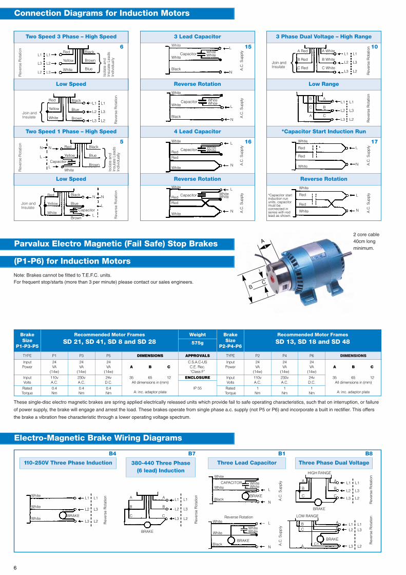
Connection Diagrams for Induction Motors
P1 P3 P5 DIMENSIONS APPROVALS TYPE P2 P4 P6
BrakeSize
P1-P3-P5
Weight
575g
BrakeSize
P2-P4-P6
Recommended Motor Frames
SD 21, SD 41, SD 8 and SD 28Recommended Motor Frames
SD 13, SD 18 and SD 48
InputPower
InputVolts
RatedTorque
110vA.C.
0.4Nm
230vA.C.
0.4Nm
24vD.C.
0.4Nm
ENCLOSURE
IP 55
InputVolts
RatedTorque
110vA.C.
1Nm
230vA.C.
1Nm
24vD.C.
1Nm
24VA
(14w)
24VA
(14w)
24VA
(14w)A B C
35 65 12All dimensions in (mm)
A: inc. adaptor plate
C.S.A.C-USC.E. Rec.“Class F”
InputPower
24VA
(14w)
24VA
(14w)
24VA
(14w)A B C
35 65 12All dimensions in (mm)
A: inc. adaptor plate
6
5 17
Two Speed 3 Phase – High Speed
Low Speed
Two Speed 1 Phase – High Speed
Low Speed
3 Lead Capacitor
Reverse Rotation
4 Lead Capacitor
Reverse Rotation
3 Phase Dual Voltage – High Range
Low Range
*Capacitor Start Induction Run
Reverse Rotation
Parvalux Electro Magnetic (Fail Safe) Stop Brakes
(P1-P6) for Induction Motors
Note: Brakes cannot be fitted to T.E.F.C. units.For frequent stop/starts (more than 3 per minute) please contact our sales engineers.
2 core cable40cm longminimum.
BC
These single-disc electro magnetic brakes are spring applied electrically released units which provide fail to safe operating characteristics, such that on interruption, or failure
of power supply, the brake will engage and arrest the load. These brakes operate from single phase a.c. supply (not P5 or P6) and incorporate a built in rectifier. This offers
the brake a vibration free characteristic through a lower operating voltage spectrum.
}
}
L1 L1
L3 L2
L2 L3
White
CapacitorWhite
Black
WhiteCapacitor
White
Black
White
RedRed
White
White
Red
Red
White
WhiteCapacitor
RedRed
White
WhiteWhite
WhiteWhite
WhiteWhite
WhiteWhite
N N
L
L
N N
L
L
Red
Yellow
White
Red
Yellow
Capacitor
Red
Yellow
White
Red
Yellow
White
Black
Brown
Blue
Black
Blue
Brown
Black
Blue
Brown
Black
Blue
Brown
Capacitor
15
16
10
A.C
. Sup
ply
Rev
erse
Rot
atio
n
A.C
. Sup
ply
Rev
erse
Rot
atio
n
A.C
. Sup
ply
A.C
. Sup
ply
A.C
. Sup
ply
A.C
. Sup
ply
Join andInsulate
*Capacitor startinduction rununits, capacitormust beconnected inseries with redlead as shown.
}
}
L1 L1
L2 L3
L3 L2
L1 L1
L2 L3
L3 L2
L1 L1
L2 L3
L3 L2
L
N
L
N
L
N
L
N
L
N
L
N
White
Red
Red
White
A Red A White
B Red B White
C Red C White
B A
C B
A C
White
CAPACITORWhite
Black
WhiteWhite
BRAKE
A.C
. Sup
ply
L
N
White
White
Black
WhiteWhite
BRAKE
A.C
. Sup
ply
L
N
Rev
erse
Rot
atio
n
L1 L1
L2 L3
L3 L2
HIGH RANGE
A A
B B
C C
BRAKE
Rev
erse
Rot
atio
n
L1 L1L2 L3
L3 L2
LOW RANGE
B A
C B
BRAKEC1A
Electro-Magnetic Brake Wiring Diagrams
110-250V Three Phase Induction 380-440 Three Phase(6 lead) Induction
Three Phase Dual VoltageThree Lead Capacitor
Rev
erse
Rot
atio
n
B4 B7 B1 B8
L1 L1
L2 L3
L3 L2
White
White
WhiteBRAKE
Rev
erse
Rot
atio
n
L1 L1
L2 L3
L3 L2
A A
B B
C C
BRAKE
White
Reverse Rotation
} Capacitor
Capacitor
Capacitor
Capacitor
A
6
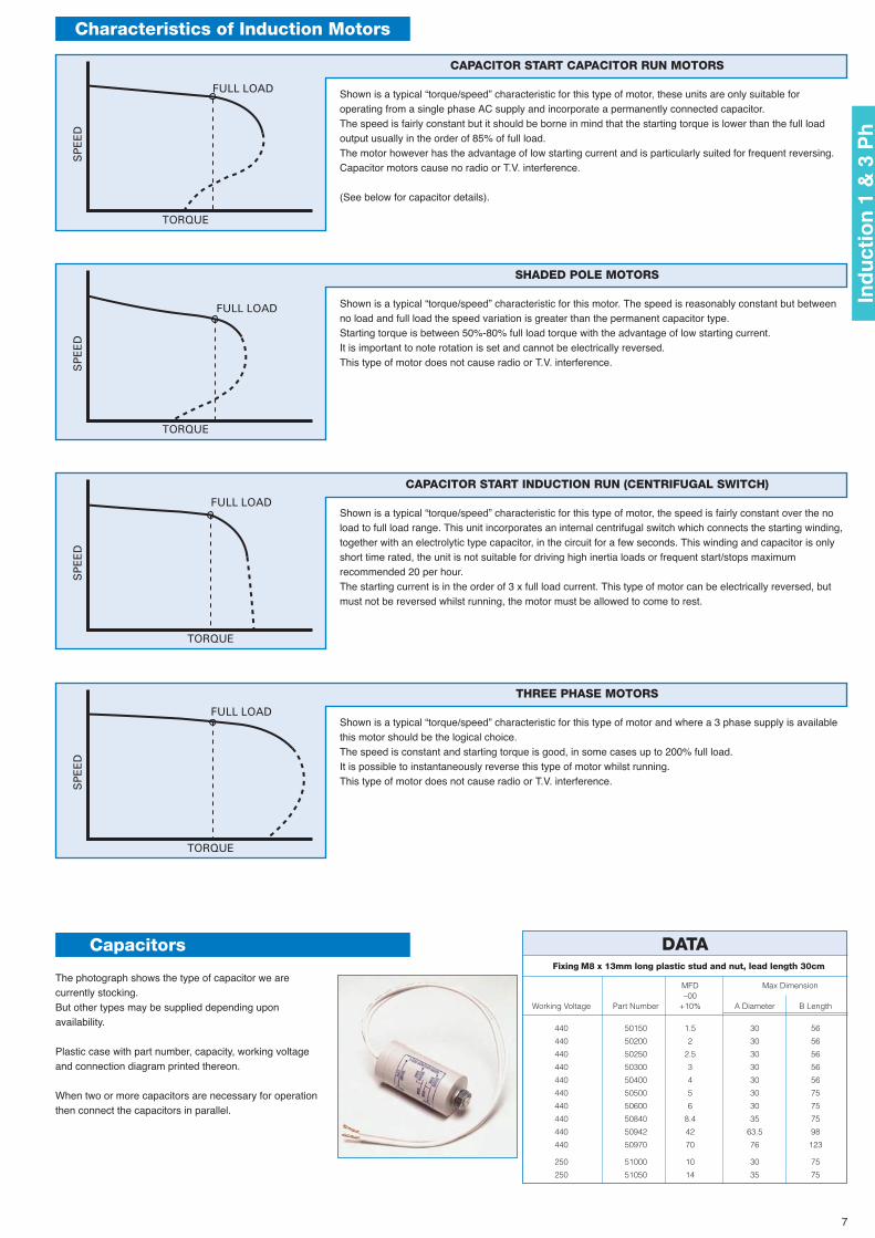
Characteristics of Induction Motors
TORQUE
FULL LOADS
PE
ED
CAPACITOR START CAPACITOR RUN MOTORS
Shown is a typical “torque/speed” characteristic for this type of motor, these units are only suitable foroperating from a single phase AC supply and incorporate a permanently connected capacitor.The speed is fairly constant but it should be borne in mind that the starting torque is lower than the full loadoutput usually in the order of 85% of full load.The motor however has the advantage of low starting current and is particularly suited for frequent reversing.Capacitor motors cause no radio or T.V. interference.
(See below for capacitor details).
SHADED POLE MOTORS
Shown is a typical “torque/speed” characteristic for this motor. The speed is reasonably constant but betweenno load and full load the speed variation is greater than the permanent capacitor type.Starting torque is between 50%-80% full load torque with the advantage of low starting current.It is important to note rotation is set and cannot be electrically reversed.This type of motor does not cause radio or T.V. interference.
TORQUE
FULL LOAD
SP
EE
D
CAPACITOR START INDUCTION RUN (CENTRIFUGAL SWITCH)
Shown is a typical “torque/speed” characteristic for this type of motor, the speed is fairly constant over the noload to full load range. This unit incorporates an internal centrifugal switch which connects the starting winding,together with an electrolytic type capacitor, in the circuit for a few seconds. This winding and capacitor is onlyshort time rated, the unit is not suitable for driving high inertia loads or frequent start/stops maximumrecommended 20 per hour.The starting current is in the order of 3 x full load current. This type of motor can be electrically reversed, butmust not be reversed whilst running, the motor must be allowed to come to rest.
TORQUE
FULL LOAD
SP
EE
D
THREE PHASE MOTORS
Shown is a typical “torque/speed” characteristic for this type of motor and where a 3 phase supply is availablethis motor should be the logical choice.The speed is constant and starting torque is good, in some cases up to 200% full load.It is possible to instantaneously reverse this type of motor whilst running.This type of motor does not cause radio or T.V. interference.
The photograph shows the type of capacitor we arecurrently stocking.But other types may be supplied depending uponavailability.
Plastic case with part number, capacity, working voltageand connection diagram printed thereon.
When two or more capacitors are necessary for operationthen connect the capacitors in parallel.
Capacitors DATAFixing M8 x 13mm long plastic stud and nut, lead length 30cm
MFD Max Dimension–00
Working Voltage Part Number +10% A Diameter B Length
440 50150 1.5 30 56
440 50200 2 30 56
440 50250 2.5 30 56
440 50300 3 30 56
440 50400 4 30 56
440 50500 5 30 75
440 50600 6 30 75
440 50840 8.4 35 75
440 50942 42 63.5 98
440 50970 70 76 123
250 51000 10 30 75
250 51050 14 35 75
TORQUE
FULL LOAD
SP
EE
D
7
Ind
uct
ion
1 &
3 P
h
220V
220V
CAPACITOR (M.F.D.)
CAPACITOR (M.F.D.)
FULL LOADR.P.M.
FULL LOADR.P.M.
220VM.F.D.
RATINGFULL LOADR.P.M.
OUTPUTWATTS
STARTINGTORQUE
FULLLOAD
INPUTWATTS
CURRENT (AMPS)
240V 220V
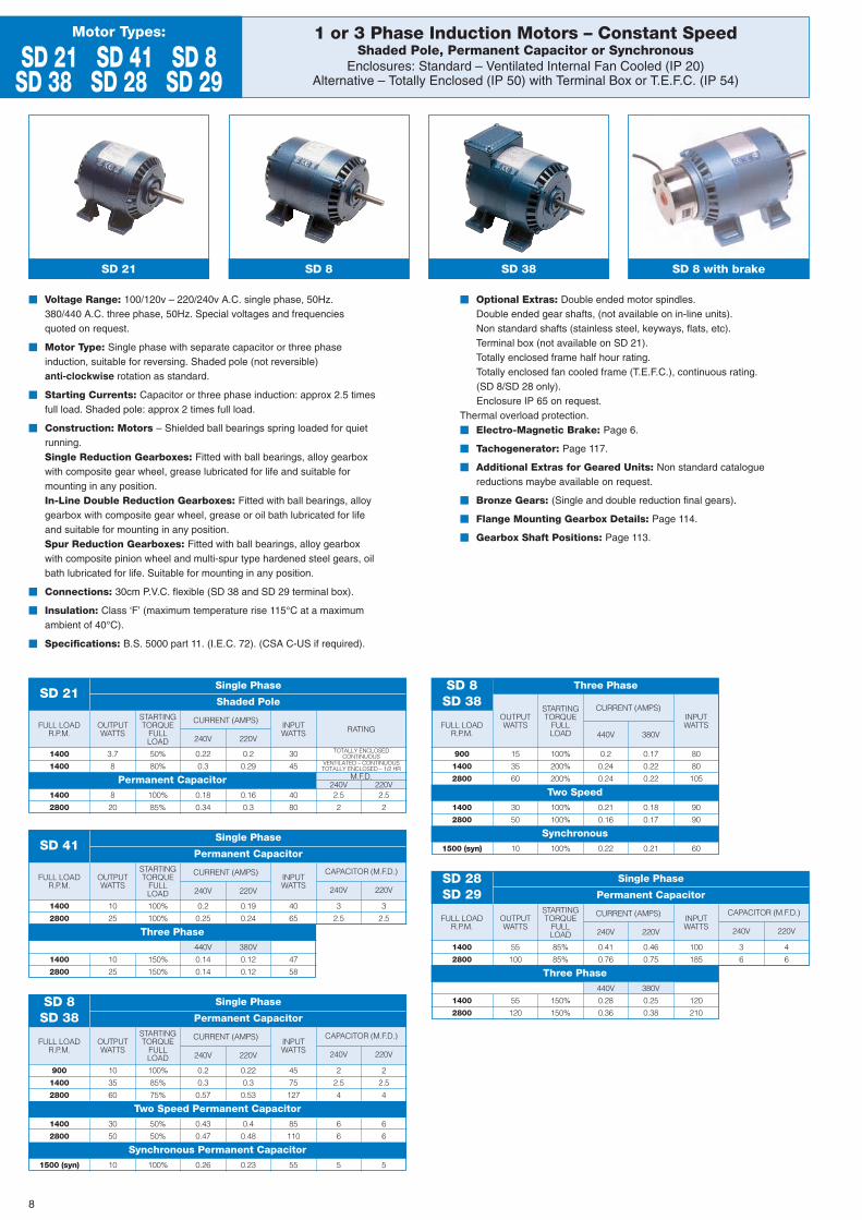
1 or 3 Phase Induction Motors – Constant SpeedShaded Pole, Permanent Capacitor or Synchronous
Enclosures: Standard – Ventilated Internal Fan Cooled (IP 20)Alternative – Totally Enclosed (IP 50) with Terminal Box or T.E.F.C. (IP 54)
Motor Types:
SD 21 SD 41 SD 8SD 38 SD 28 SD 29
SD 21 SD 8 SD 38
� Voltage Range: 100/120v – 220/240v A.C. single phase, 50Hz.380/440 A.C. three phase, 50Hz. Special voltages and frequenciesquoted on request.
� Motor Type: Single phase with separate capacitor or three phaseinduction, suitable for reversing. Shaded pole (not reversible)anti-clockwise rotation as standard.
� Starting Currents: Capacitor or three phase induction: approx 2.5 timesfull load. Shaded pole: approx 2 times full load.
� Construction: Motors – Shielded ball bearings spring loaded for quietrunning.Single Reduction Gearboxes: Fitted with ball bearings, alloy gearboxwith composite gear wheel, grease lubricated for life and suitable formounting in any position.In-Line Double Reduction Gearboxes: Fitted with ball bearings, alloygearbox with composite gear wheel, grease or oil bath lubricated for lifeand suitable for mounting in any position.Spur Reduction Gearboxes: Fitted with ball bearings, alloy gearboxwith composite pinion wheel and multi-spur type hardened steel gears, oilbath lubricated for life. Suitable for mounting in any position.
� Connections: 30cm P.V.C. flexible (SD 38 and SD 29 terminal box).
� Insulation: Class ‘F’ (maximum temperature rise 115°C at a maximumambient of 40°C).
� Specifications: B.S. 5000 part 11. (I.E.C. 72). (CSA C-US if required).
� Optional Extras: Double ended motor spindles.Double ended gear shafts, (not available on in-line units).Non standard shafts (stainless steel, keyways, flats, etc).Terminal box (not available on SD 21).Totally enclosed frame half hour rating.Totally enclosed fan cooled frame (T.E.F.C.), continuous rating.(SD 8/SD 28 only).Enclosure IP 65 on request.
Thermal overload protection.� Electro-Magnetic Brake: Page 6.
� Tachogenerator: Page 117.
� Additional Extras for Geared Units: Non standard cataloguereductions maybe available on request.
� Bronze Gears: (Single and double reduction final gears).
� Flange Mounting Gearbox Details: Page 114.
� Gearbox Shaft Positions: Page 113.
SD 21Single Phase
Permanent Capacitor
Shaded Pole
SD 8 with brake
1400
1400
1400
2800
3.7
8
8
20
0.22
0.3
0.18
0.34
0.2
0.29
0.16
0.3
30
45
40
80
2.5
2
240V2.5
2
TOTALLY ENCLOSEDCONTINUOUS
VENTILATED – CONTINUOUSTOTALLY ENCLOSED – 1/2 HR
50%
80%
100%
85%
FULL LOADR.P.M.
OUTPUTWATTS
STARTINGTORQUE
FULLLOAD
INPUTWATTS
CURRENT (AMPS)
440V 380V
SD 8SD 38
Two Speed
Synchronous
900
1400
2800
1400
2800
1500 (syn)
15
35
60
30
50
10 100% 0.22 0.21 60
0.2
0.24
0.24
0.21
0.16
0.17
0.22
0.22
0.18
0.17
80
80
105
90
90
100%
200%
200%
100%
100%
240V
240V
OUTPUTWATTS
OUTPUTWATTS
STARTINGTORQUE
FULLLOAD
STARTINGTORQUE
FULLLOAD
INPUTWATTS
INPUTWATTS
CURRENT (AMPS)
CURRENT (AMPS)
240V
240V
220V
220V
SD 41
SD 8SD 38
Single Phase
Single Phase
Three Phase
Permanent Capacitor
Permanent Capacitor
Two Speed Permanent Capacitor
Synchronous Permanent Capacitor
1400
2800
900
1400
2800
1400
2800
1500 (syn)
1400
2800
10
25
10
35
60
30
50
10
50%
50%
100%
0.43
0.47
0.26
0.4
0.48
0.23
85
110
55
6
6
5
6
6
5
10
25
0.2
0.25
0.2
0.3
0.57
0.14
0.14
440V 380V
0.19
0.24
0.22
0.3
0.53
0.12
0.12
40
65
45
75
127
3
2.5
2
2.5
4
3
2.5
2
2.5
4
47
58
100%
100%
100%
85%
75%
150%
150%
220V
CAPACITOR (M.F.D.)FULL LOAD
R.P.M. 240V
OUTPUTWATTS
STARTINGTORQUE
FULLLOAD
INPUTWATTS
CURRENT (AMPS)
240V 220V
SD 28SD 29
Single Phase
Three Phase
Permanent Capacitor
1400
2800
1400
2800
55
100
55
120
0.41
0.76
0.28
0.36
440V 380V
0.46
0.75
0.25
0.38
100
185
3
6
4
6
120
210
85%
85%
150%
150%
8
Three Phase
SD 21 SD 41
38
4.3
7.92
07.
927
Ø
10795Ø 51
7.92
0Ø
7.92
74.3
38
Ø 35
Ø 81
83
38
5924.8
15 x 5.1SLOT
5
42.8
70
46.4
25SLOT
15 x 5.1
24.8
92
73
51
73
144
SD 28
4.3
7.92
07.
927
Ø
38
SD 8
125
38
Ø 96
Ø 51
7.92
0Ø
7.92
7
4.3 Ø 35
Ø 77 184 (T.E.F.C.)165 (T.E.F.C.)
Ø 107
80
83.3
115
56
30.2
18.5 x 7.1 SLOT
30.2
96
64.3
3718.5 x 7.1 SLOT
6.7
111
92
67
52.4
30
147
4.3
7.92
77.
920
SD 29
38
Ø
SD 38
30
128
Ø 96
Ø 51
7.92
0Ø
7.92
7
4.3
38
Ø 35
Ø 77
5618.5 x 7.1 SLOT
115
30 83.3
18.5 x 7.1 SLOT
115
6.7
96
64.3
37
30
111
92
67
52.4
SD 21SD 41
SD 8SD 28
SD 38SD 29
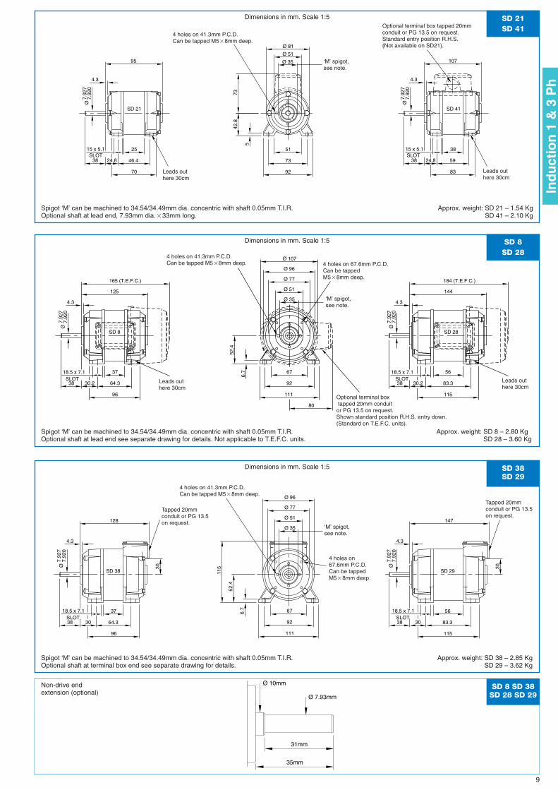
Dimensions in mm. Scale 1:5
Dimensions in mm. Scale 1:5
Dimensions in mm. Scale 1:5
Spigot ‘M’ can be machined to 34.54/34.49mm dia. concentric with shaft 0.05mm T.I.R.Optional shaft at lead end, 7.93mm dia.�33mm long.
Spigot ‘M’ can be machined to 34.54/34.49mm dia. concentric with shaft 0.05mm T.I.R.Optional shaft at lead end see separate drawing for details. Not applicable to T.E.F.C. units.
Spigot ‘M’ can be machined to 34.54/34.49mm dia. concentric with shaft 0.05mm T.I.R.Optional shaft at terminal box end see separate drawing for details.
Approx. weight: SD 21 – 1.54 KgSD 41 – 2.10 Kg
Approx. weight: SD 8 – 2.80 KgSD 28 – 3.60 Kg
Approx. weight: SD 38 – 2.85 KgSD 29 – 3.62 Kg
Leads outhere 30cm
Leads outhere 30cm
Optional terminal box tapped 20mmconduit or PG 13.5 on request.Standard entry position R.H.S. (Not available on SD21).
4 holes on 41.3mm P.C.D.Can be tapped M5�8mm deep.
Leads outhere 30cm
Tapped 20mmconduit or PG 13.5on request.
Tapped 20mmconduit or PG 13.5on request.
Leads outhere 30cm
4 holes on 41.3mm P.C.D.Can be tapped M5�8mm deep.
4 holes on 41.3mm P.C.D.Can be tapped M5�8mm deep.
4 holes on 67.6mm P.C.D.Can be tappedM5�8mm deep.
4 holes on67.6mm P.C.D.Can be tappedM5�8mm deep.
‘M’ spigot,see note.
‘M’ spigot,see note.
‘M’ spigot,see note.
Optional terminal boxtapped 20mm conduitor PG 13.5 on request.Shown standard position R.H.S. entry down.(Standard on T.E.F.C. units).
Non-drive end extension (optional)
9
Ind
uct
ion
1 &
3 P
h
Ø 10mm
Ø 7.93mm
31mm
35mm
SD 8 SD 38SD 28 SD 29
INPUTWATTSFULL LOAD
R.P.M.
INPUTWATTSFULL LOAD
R.P.M.
220/240V
220V
CAPACITOR (M.F.D.)
FULL LOADR.P.M.
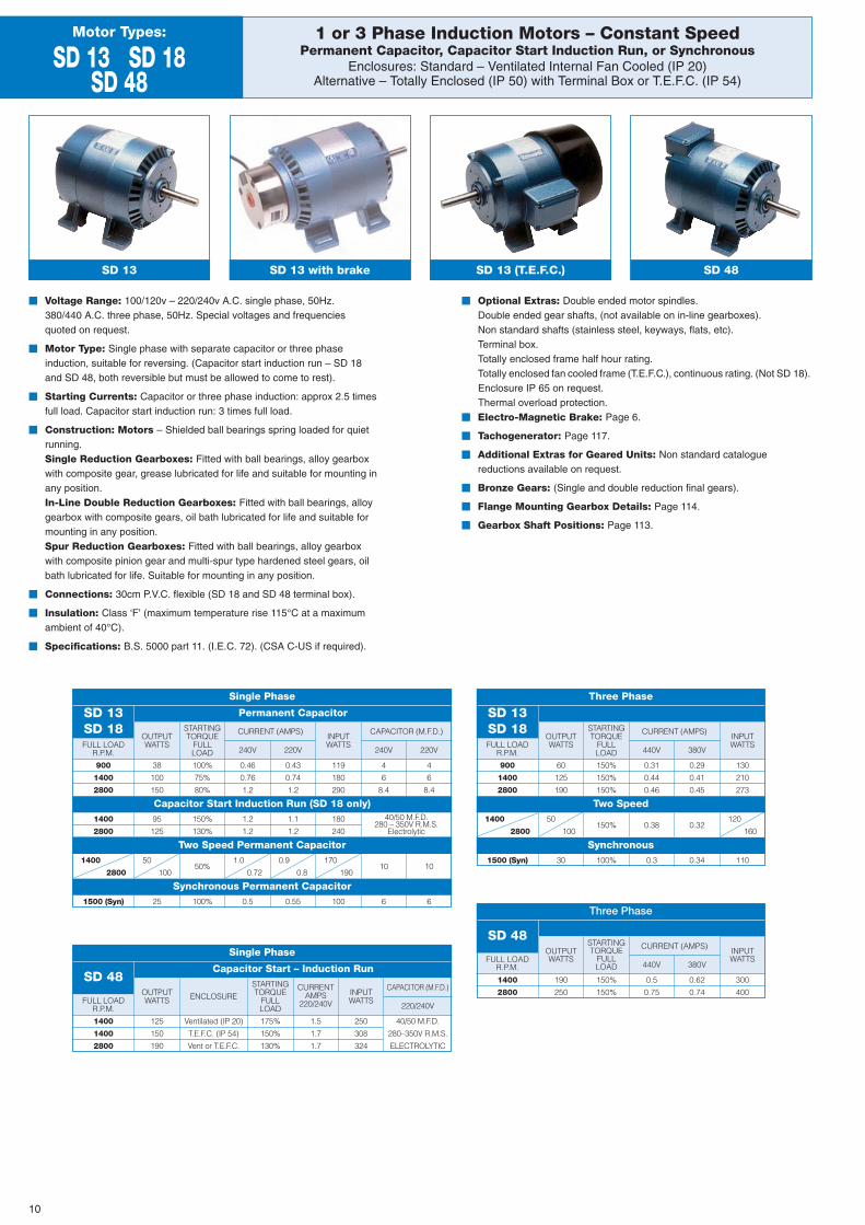
1 or 3 Phase Induction Motors – Constant SpeedPermanent Capacitor, Capacitor Start Induction Run, or Synchronous
Enclosures: Standard – Ventilated Internal Fan Cooled (IP 20)Alternative – Totally Enclosed (IP 50) with Terminal Box or T.E.F.C. (IP 54)
Motor Types:
SD 13 SD 18SD 48
SD 13 with brake SD 13 (T.E.F.C.)
� Voltage Range: 100/120v – 220/240v A.C. single phase, 50Hz.380/440 A.C. three phase, 50Hz. Special voltages and frequenciesquoted on request.
� Motor Type: Single phase with separate capacitor or three phaseinduction, suitable for reversing. (Capacitor start induction run – SD 18and SD 48, both reversible but must be allowed to come to rest).
� Starting Currents: Capacitor or three phase induction: approx 2.5 timesfull load. Capacitor start induction run: 3 times full load.
� Construction: Motors – Shielded ball bearings spring loaded for quietrunning.Single Reduction Gearboxes: Fitted with ball bearings, alloy gearboxwith composite gear, grease lubricated for life and suitable for mounting inany position.In-Line Double Reduction Gearboxes: Fitted with ball bearings, alloygearbox with composite gears, oil bath lubricated for life and suitable formounting in any position.Spur Reduction Gearboxes: Fitted with ball bearings, alloy gearboxwith composite pinion gear and multi-spur type hardened steel gears, oilbath lubricated for life. Suitable for mounting in any position.
� Connections: 30cm P.V.C. flexible (SD 18 and SD 48 terminal box).
� Insulation: Class ‘F’ (maximum temperature rise 115°C at a maximumambient of 40°C).
� Specifications: B.S. 5000 part 11. (I.E.C. 72). (CSA C-US if required).
� Optional Extras: Double ended motor spindles.Double ended gear shafts, (not available on in-line gearboxes).Non standard shafts (stainless steel, keyways, flats, etc).Terminal box.Totally enclosed frame half hour rating.Totally enclosed fan cooled frame (T.E.F.C.), continuous rating. (Not SD 18).Enclosure IP 65 on request.Thermal overload protection.
� Electro-Magnetic Brake: Page 6.
� Tachogenerator: Page 117.
� Additional Extras for Geared Units: Non standard cataloguereductions available on request.
� Bronze Gears: (Single and double reduction final gears).
� Flange Mounting Gearbox Details: Page 114.
� Gearbox Shaft Positions: Page 113.
SD 48
240V
OUTPUTWATTS
STARTINGTORQUE
FULLLOAD
INPUTWATTS
CURRENT (AMPS)
240V 220V
SD 13SD 18
Single Phase
Capacitor Start Induction Run (SD 18 only)
Two Speed Permanent Capacitor
Synchronous Permanent Capacitor
Permanent Capacitor
900
1400
2800
1400
2800
1400
2800
1500 (Syn)
38
100
150
95
125
50
100
25 100% 0.5 0.55 100 6 6
0.46
0.76
1.2
0.43
0.74
1.2
119
180
290
4
6
8.4
4
6
8.4
100%
75%
80%
150%
130%
50%1.0
0.72
0.9
0.8
170
19010 10
1.2
1.2
1.1
1.2
180
240
40/50 M.F.D.280 – 350V R.M.S.
Electrolytic
CAPACITOR (M.F.D.)
FULL LOADR.P.M.
OUTPUTWATTS ENCLOSURE INPUT
WATTS
STARTINGTORQUE
FULLLOAD
CURRENTAMPS
220/240V
SD 48
Single Phase
Capacitor Start – Induction Run
1400
1400
2800
125
150
190
175%
150%
130%
1.5
1.7
1.7
250
308
324
40/50 M.F.D.
280–350V R.M.S.
ELECTROLYTIC
Ventilated (IP 20)
T.E.F.C. (IP 54)
Vent or T.E.F.C.
OUTPUTWATTS
STARTINGTORQUE
FULLLOAD
CURRENT (AMPS)
440V 380V
Three Phase
Two Speed
Synchronous
900
1400
2800
1400
2800
1500 (Syn)
60
125
190
50
100
30 100% 0.3 0.34 110
0.31
0.44
0.46
0.29
0.41
0.45
130
210
273
150%
150%
150%
150% 0.38 0.32120
160
Three Phase
SD 48
SD 13SD 18
OUTPUTWATTS
STARTINGTORQUE
FULLLOAD
CURRENT (AMPS)
440V 380V
1400
2800
190
250
150%
150%
0.5
0.75
0.62
0.74
300
400
SD 13
10
152
Ø 120
Ø 59
11.9
9Ø
12.0
0
4.3
50.8
Ø 35
Ø 89
Ø 131190 (T.E.F.C.)
94
24 x 7.1
8
11175.346SLOT
38.613411182
66.7
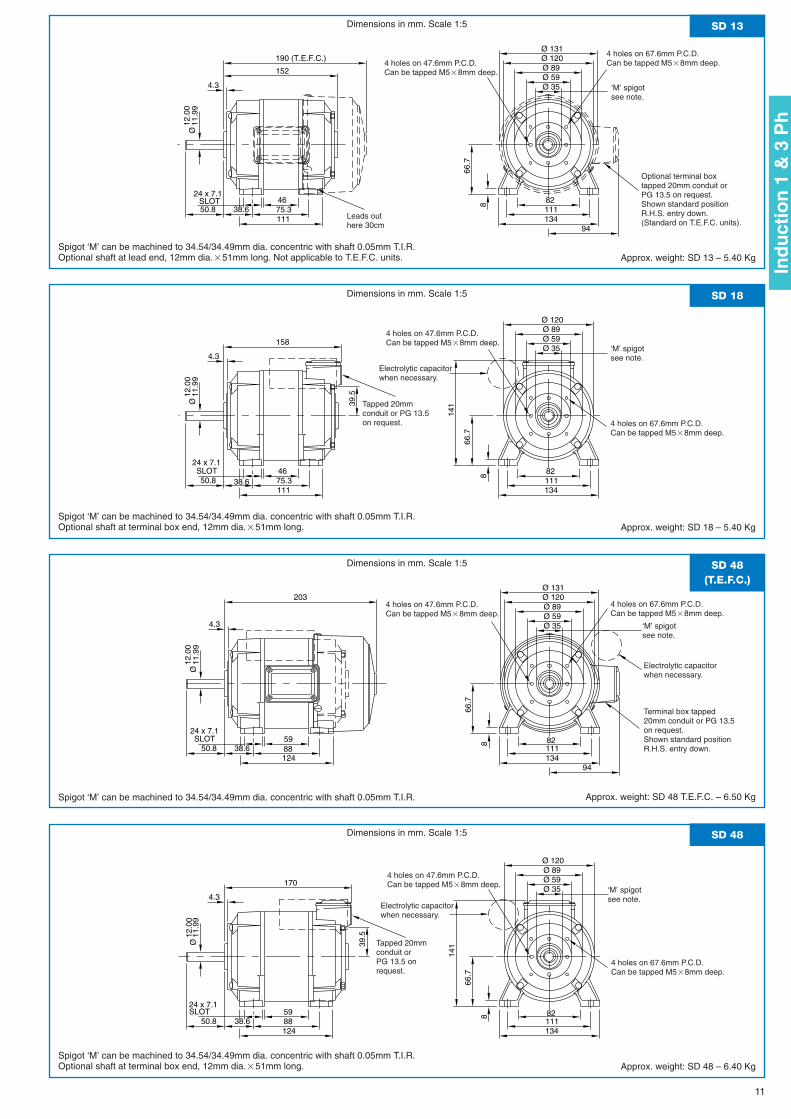
SD 13Dimensions in mm. Scale 1:5
Approx. weight: SD 13 – 5.40 Kg
39.5
158
Ø 120
Ø 59
11.9
9Ø
12.0
0
4.3
50.8
Ø 35
Ø 89
141
24 x 7.1
811175.346SLOT
38.613411182
66.7
SD 18Dimensions in mm. Scale 1:5
Ø 131
94
203 Ø 120
Ø 59
11.9
9Ø
12.0
0
4.3
50.8
Ø 35
Ø 89
24 x 7.1
8
1248859SLOT
38.613411182
66.7
SD 48(T.E.F.C.)
Dimensions in mm. Scale 1:5
39.5
170
Ø 120
Ø 59
11.9
9Ø
12.0
0
4.3
50.8
Ø 35
Ø 89
141
24 x 7.1
8
1248859SLOT
38.613411182
66.7
SD 48 Dimensions in mm. Scale 1:5
Approx. weight: SD 48 – 6.40 Kg
Leads outhere 30cm
4 holes on 67.6mm P.C.D.Can be tapped M5�8mm deep.4 holes on 47.6mm P.C.D.
Can be tapped M5�8mm deep.
Electrolytic capacitorwhen necessary.
4 holes on 47.6mm P.C.D.Can be tapped M5�8mm deep.
4 holes on 67.6mm P.C.D.Can be tapped M5�8mm deep.
‘M’ spigotsee note.
‘M’ spigotsee note.
‘M’ spigotsee note.
‘M’ spigotsee note.
4 holes on 47.6mm P.C.D.Can be tapped M5�8mm deep.
4 holes on 67.6mm P.C.D.Can be tapped M5�8mm deep.
Optional terminal boxtapped 20mm conduit orPG 13.5 on request.Shown standard positionR.H.S. entry down.(Standard on T.E.F.C. units).
Tapped 20mmconduit or PG 13.5on request.
Electrolytic capacitorwhen necessary.
Terminal box tapped20mm conduit or PG 13.5on request.Shown standard positionR.H.S. entry down.
Spigot ‘M’ can be machined to 34.54/34.49mm dia. concentric with shaft 0.05mm T.I.R.Optional shaft at lead end, 12mm dia.�51mm long. Not applicable to T.E.F.C. units.
Spigot ‘M’ can be machined to 34.54/34.49mm dia. concentric with shaft 0.05mm T.I.R.Optional shaft at terminal box end, 12mm dia.�51mm long.
Spigot ‘M’ can be machined to 34.54/34.49mm dia. concentric with shaft 0.05mm T.I.R.Optional shaft at terminal box end, 12mm dia.�51mm long.
Approx. weight: SD 18 – 5.40 Kg
Approx. weight: SD 48 T.E.F.C. – 6.50 KgSpigot ‘M’ can be machined to 34.54/34.49mm dia. concentric with shaft 0.05mm T.I.R.
4 holes on 47.6mm P.C.D.Can be tapped M5�8mm deep.
4 holes on 67.6mm P.C.D.Can be tapped M5�8mm deep.
Electrolytic capacitorwhen necessary.
Tapped 20mmconduit orPG 13.5 onrequest.
11
Ind
uct
ion
1 &
3 P
h
OUTPUT TORQUE (Nm)
COMPOSITE
FINALR.P.M.
------
2.92.92.92.92.92.92.92.92.92.92.92.832.712.602.492.262.031.811.581.471.241.02
------
2.92.92.92.92.92.92.92.92.92.92.92.92.92.92.92.712.372.151.811.701.471.24
FINALR.P.M.
BRONZECOMPOSITEBRONZECOMPOSITECOMPOSITE
COMPOSITE BRONZE COMPOSITE BRONZE
COMPOSITE
BRONZE
OUTPUT TORQUE (Nm)
OUTPUT TORQUE (Nm)
COMPOSITE
COMPOSITE COMPOSITECOMPOSITE
RATIO
RATIO RATIO
FINALR.P.M.
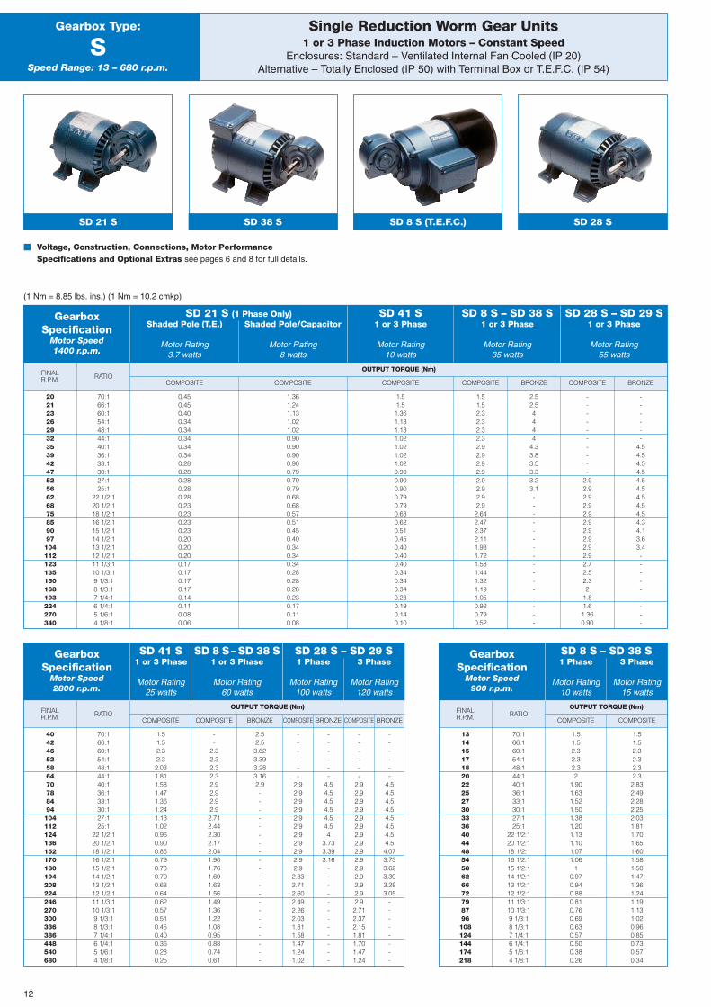
Single Reduction Worm Gear Units1 or 3 Phase Induction Motors – Constant Speed
Enclosures: Standard – Ventilated Internal Fan Cooled (IP 20)Alternative – Totally Enclosed (IP 50) with Terminal Box or T.E.F.C. (IP 54)
Gearbox Type:
SSpeed Range: 13 – 680 r.p.m.
SD 21 S SD 38 S SD 8 S (T.E.F.C.) SD 28 S
� Voltage, Construction, Connections, Motor PerformanceSpecifications and Optional Extras see pages 6 and 8 for full details.
(1 Nm = 8.85 lbs. ins.) (1 Nm = 10.2 cmkp)
GearboxSpecification
Motor Speed1400 r.p.m.
SD 8 S – SD 38 S1 or 3 Phase
Motor Rating35 watts
SD 28 S – SD 29 S1 or 3 Phase
Motor Rating55 watts
SD 41 S1 or 3 Phase
Motor Rating10 watts
SD 21 S (1 Phase Only)Shaded Pole (T.E.) Shaded Pole/Capacitor
Motor Rating Motor Rating3.7 watts 8 watts
202123262932353942475256626875859097104112123135150168193224270340
70:166:160:154:148:144:140:136:133:130:127:125:1
22 1/2:120 1/2:118 1/2:116 1/2:115 1/2:114 1/2:113 1/2:112 1/2:111 1/3:110 1/3:19 1/3:18 1/3:17 1/4:16 1/4:15 1/6:14 1/8:1
70:166:160:154:148:144:140:136:133:130:127:125:1
22 1/2:120 1/2:118 1/2:116 1/2:115 1/2:114 1/2:113 1/2:112 1/2:111 1/3:110 1/3:19 1/3:18 1/3:17 1/4:16 1/4:15 1/6:14 1/8:1
70:166:160:154:148:144:140:136:133:130:127:125:1
22 1/2:120 1/2:118 1/2:116 1/2:115 1/2:114 1/2:113 1/2:112 1/2:111 1/3:110 1/3:19 1/3:18 1/3:17 1/4:16 1/4:15 1/6:14 1/8:1
0.450.450.400.340.340.340.340.340.280.280.280.280.280.230.230.230.230.200.200.200.170.170.170.170.140.110.080.06
1.51.52.32.32.031.811.581.471.361.241.131.020.960.900.850.790.730.700.680.640.620.570.510.450.400.360.280.25
1.51.52.32.32.32
1.901.631.521.501.381.201.131.101.071.06
10.970.940.880.810.760.690.630.570.500.380.26
1.51.52.32.32.32.32.832.492.282.252.031.811.701.651.601.581.501.471.361.241.191.131.020.960.850.730.570.34
1.361.241.131.021.020.900.900.900.900.790.790.790.680.680.570.510.450.400.340.340.340.280.280.280.230.170.110.08
--
2.32.32.32.32.92.92.92.92.712.442.302.172.041.901.761.691.631.561.491.361.221.080.950.880.740.61
1.51.51.361.131.131.021.021.021.020.900.900.900.790.790.680.620.510.450.400.400.400.340.340.340.280.190.140.10
2.52.53.623.393.283.162.9---------------------
1.51.52.32.32.32.32.92.92.92.92.92.92.92.92.642.472.372.111.981.721.581.441.321.191.050.920.790.52
2.52.54444
4.33.83.53.33.23.1----------------
------
4.54.54.54.54.54.54
3.733.393.16
------------
----------
2.92.92.92.92.92.92.92.92.92.92.72.52.32
1.81.61.360.90
------
4.54.54.54.54.54.54.54.54.54.34.13.63.4---------
------
4.54.54.54.54.54.54.54.54.073.733.623.393.283.05
--------
GearboxSpecification
Motor Speed2800 r.p.m.
GearboxSpecification
Motor Speed900 r.p.m.
SD 41 S1 or 3 Phase
Motor Rating25 watts
SD 8 S – SD 38 S1 or 3 Phase
Motor Rating60 watts
SD 28 S – SD 29 S1 Phase 3 Phase
Motor Rating Motor Rating100 watts 120 watts
SD 8 S – SD 38 S1 Phase 3 Phase
Motor Rating Motor Rating10 watts 15 watts
40424652586470788494104112124136152170180194208224246270300336386448540680
1314151718202225273033364044485458626672798796108124144174218
12
27.527.5
4429
SD 21 SD 41
162150
Ø 81
68.2
51.5
97
83
38
59
15 x 5.1SLOT
5
42.8
70
46.4
25SLOT
15 x 5.1
51.5
92
73
51
48
44
27.527.5
29
199
SD 28SD 8
180
Ø 96 239 (T.E.F.C.)220 (T.E.F.C.)
Ø 107
80
77.8
57.6
106
83.3
115
5618.5 x 7.1 SLOT
57.6
96
64.3
3718.5 x 7.1 SLOT 6.
7
111
92
67
52.4
30
202
30
183
44
27.527.5
29
SD 29SD 38
Ø 96
115
77.8
57.6
106
83.3
115
5618.5 x 7.1 SLOT
57.6
96
64.3
3718.5 x 7.1 SLOT 6.
7
111
92
67
52.4
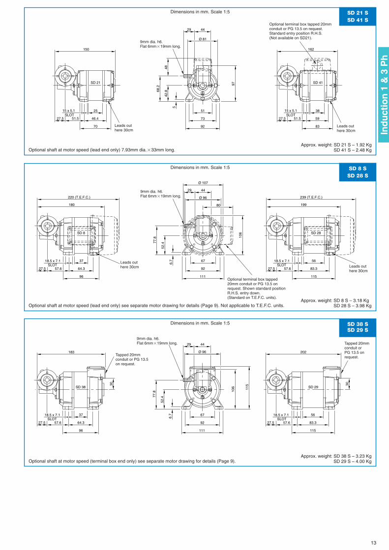
SD 21 SSD 41 S
SD 8 SSD 28 S
SD 38 SSD 29 S
Dimensions in mm. Scale 1:5
Dimensions in mm. Scale 1:5
Dimensions in mm. Scale 1:5
Optional shaft at motor speed (lead end only) 7.93mm dia.�33mm long.
Optional shaft at motor speed (lead end only) see separate motor drawing for details (Page 9). Not applicable to T.E.F.C. units.
Optional shaft at motor speed (terminal box end only) see separate motor drawing for details (Page 9).
Approx. weight: SD 21 S – 1.92 KgSD 41 S – 2.48 Kg
Approx. weight: SD 8 S – 3.18 KgSD 28 S – 3.98 Kg
Approx. weight: SD 38 S – 3.23 KgSD 29 S – 4.00 Kg
Leads outhere 30cm
Leads outhere 30cm
Optional terminal box tapped 20mmconduit or PG 13.5 on request.Standard entry position R.H.S.(Not available on SD21).
9mm dia. h6.Flat 6mm�19mm long.
Leads outhere 30cm
Tapped 20mmconduit or PG 13.5on request.
Leads outhere 30cm
9mm dia. h6.Flat 6mm�19mm long.
9mm dia. h6.Flat 6mm�19mm long.
Optional terminal box tapped20mm conduit or PG 13.5 onrequest. Shown standard positionR.H.S. entry down.(Standard on T.E.F.C. units).
Tapped 20mmconduit orPG 13.5 onrequest.
13
Ind
uct
ion
1 &
3 P
h

BRONZE
OUTPUT TORQUE (Nm)FINALR.P.M.
--
5.95.95.95.97.97.97.97.97.97.97.67.36.76.36
5.75.45.35.14.44.13.83.42.82.52.2
BRONZE
OUTPUT TORQUE (Nm)FINALR.P.M. COMPOSITE BRONZE COMPOSITE
--
5.95.95.95.97.97.97.87.36.76.56
5.75.35
4.74.54.34.34
3.53.33
2.82.32
1.8
BRONZECOMPOSITEBRONZECOMPOSITECOMPOSITE BRONZE
COMPOSITE BRONZE COMPOSITE
COMPOSITE BRONZE
COMPOSITE BRONZE
OUTPUT TORQUE (Nm)
COMPOSITE BRONZE
COMPOSITE COMPOSITE COMPOSITECOMPOSITE BRONZE
RATIO
RATIO RATIO
FINALR.P.M.
Single Reduction Worm Gear Units1 or 3 Phase Induction Motors – Constant Speed
Enclosures: Standard – Ventilated Internal Fan Cooled (IP 20)Alternative – Totally Enclosed (IP 50) with Terminal Box or T.E.F.C. (IP 54)
Gearbox Type:
MSpeed Range: 12 – 680 r.p.m.
SD 28 M SD 8 M (T.E.F.C.) SD 38 M
� Voltage, Construction, Connections, Motor Performance Specificationsand Optional Extras see pages 6, 8 and 10 for full details.Hollow shaft available on request. Maximum internal diameter 8mm.
(1 Nm = 8.85 lbs. ins.) (1 Nm = 10.2 cmkp)
GearboxSpecification
Motor Speed1400 r.p.m.
SD 28 M – SD 29 M1 or 3 Phase
Motor Rating55 watts
SD 18 M1 Phase
Motor Rating95 watts
SD 8 M – SD 38 M1 or 3 Phase
Motor Rating35 watts
SD 13 M – SD 18 M1 Phase 3 Phase
Motor Rating Motor Rating100 watts 125 watts
202123262932353942475256626875859097105113123135150168193227273340
72:166:160:154:148:144:140:136:133:130:127:125:1
22 1/2:120 1/2:118 1/2:116 1/2:115 1/2:114 1/2:113 1/3:112 1/3:111 1/3:110 1/3:19 1/3:18 1/3:17 1/4:16 1/6:15 1/8:14 1/8:1
72:166:160:154:148:144:140:136:133:130:127:125:1
22 1/2:120 1/2:118 1/2:116 1/2:115 1/2:114 1/2:113 1/3:112 1/3:111 1/3:110 1/3:19 1/3:18 1/3:17 1/4:16 1/6:15 1/8:14 1/8:1
72:166:160:154:148:144:140:136:133:130:127:125:1
22 1/2:120 1/2:118 1/2:116 1/2:115 1/2:114 1/2:113 1/3:112 1/3:111 1/3:110 1/3:19 1/3:18 1/3:17 1/4:16 1/6:15 1/6:14 1/8:1
5.15.15.14.94.64.44
3.83.73.43.23
2.82.72.52.32.22.12
1.91.81.71.61.41.31.10.90.8
6.66.56.3---
5.14.84.64.24
3.83.63.33.12.92.72.62.42.32.12
1.91.81.71.71.61.41.31.21.10.90.80.7
2.72.52.42.22.12
1.81.71.61.51.41.31.21.111
0.90.880.850.800.780.740.700.640.580.500.430.36
43.83.63.33.23
2.72.62.42.22.11.91.81.71.51.51.351.321.271.201.171.11
10.960.870.750.650.54
5.15.15.95.95.95.96.86.56.15.75.34.94.64.23.83.83.423.343.233.042.962.812.662.432.21.91.631.37
7.37.37.97.97.97.97.9---
5.15.15.95.95.95.97.97.97.97.97.97.87.26.666
5.45.35.14.84.684.444.203.843.48
32.582.16
7.37.37.97.97.97.910.810.29.69
8.4---
5.15.15.95.95.95.96.36
5.85.35
4.74.44.23.95.23.43.33.13
2.82.72.52.22.11.71.41.2
7.37.37.97.97.97.3---
--
5.95.95.95.96
5.55.24.84.54.34
3.83.53.33.23
2.82.82.72.32.22
1.81.51.31.2
--
7.26.86.3---
-----
5.97.97.97.97.97.97.97.97.77.16.66.36
5.75.45.14.84.64
3.73.12.52.2
-----
7.911.410.910.69.79.18.68---
--
5.95.95.95.95.95.95.95.85.45.24.84.64.24
3.83.63.43.43.22.82.62.42.21.81.61.4
--
7.97.97.67.16.86.26---
-----
5.97.97.97.97.97.97.97.97.97.97.97.97.57
6.86.46
5.75
4.63.93.22.9
-----
7.911.811.811.811.811.410.7109.68.98.2---
--
7.37.37.37.99
8.3
-----
5.97.97.97.97.97.97.97.67.36.86.25.95.75.45.24.94.64.33.83.53
2.42.2
----
7.97.910.910.3109.28.78.2---
--
7.97.97.97.911.410.59.89.28.68.2---
GearboxSpecification
Motor Speed2800 r.p.m.
GearboxSpecification
Motor Speed900 r.p.m.
SD 8 M – 38 M1 or 3 Phase
Motor Rating60 watts
SD 28 M – 29 M1 Phase 3 Phase
Motor Rating Motor Rating100 watts 120 watts
SD 13 M – 18 M1 Phase 3 Phase
Motor Rating Motor Rating150 watts 190 watts
SD 8 M – 38 M1 Phase 3 Phase
Motor Rating Motor Rating10 watts 15 watts
SD 13 M – 18 M1 Phase 3 Phase
Motor Rating Motor Rating38 watts 60 watts
40424652586470788493104112124136152170180194210226250270300338386456545680
1214151718202225273033364044485458626773798796108124146174218
(Capacitor startinduction run)
SD 13 M with brake
14
3434
58.752
218
SD 28SD 8
199 Ø 96
258 (T.E.F.C.)239 (T.E.F.C.) Ø 107
80
87.3
70.7
121
83.3
115
5618.5 x 7.1 SLOT
70.7
96
64.3
3718.5 x 7.1 SLOT
6.7
111
92
67
52.4
SD 8 MSD 28 M
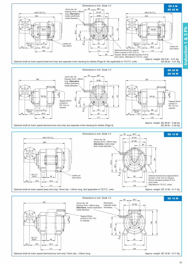
Dimensions in mm. Scale 1:5
Optional shaft at motor speed (lead end only) see separate motor drawing for details (Page 9). Not applicable to T.E.F.C. units.Approx. weight: SD 8 M – 3.51 Kg
SD 28 M – 4.31 Kg
221
3030
202
3434
58.752
SD 29SD 38
Ø 96
121
87.3
70.711
583.3
115
5618.5 x 7.1 SLOT
70.7
96
64.3
3718.5 x 7.1 SLOT 6.
7
111
92
67
52.4
SD 29 MSD 38 M
Dimensions in mm. Scale 1:5
Optional shaft at motor speed (terminal box end only) see separate motor drawing for details (Page 9).Approx. weight: SD 38 M – 3.56 Kg
SD 29 M – 4.33 Kg
226Ø 120
58.7
34
52
Ø 131264 (T.E.F.C.)
94
78.7
24 x 7.1 8
111
75.3
46SLOT
134
111
82
66.7
136
101.
6
SD 13 MDimensions in mm. Scale 1:5
Optional shaft at motor speed (lead end only) 10mm dia.�33mm long. Not applicable to T.E.F.C. units. Approx. weight: SD 13 M – 6.11 Kg
39.5
231Ø 120
58.7
34
52
141
78.7
24 x 7.1 8
111
75.3
46SLOT
134
111
82
66.7
136
101.
6
SD 18 MDimensions in mm. Scale 1:5
Optional shaft at motor speed (terminal box end only) 10mm dia.�33mm long. Approx. weight: SD 18 M – 6.11 Kg
Leads outhere 30cm Leads out
here 30cm
12mm dia. h6.Keyway 4mm�38mmlong. Alternative,hollow shaft 8mminside diameter.
12mm dia. h6.Keyway 4mm�38mmlong. Alternative,hollow shaft 8mminside diameter.
Tapped 20mmconduit or PG 13.5on request.
Tapped 20mmconduit orPG 13.5 onrequest.
12mm dia. h6.Keyway 4mm�38mm long.Alternative, hollow shaft8mm inside diameter.
Electrolyticcapacitor whennecessary.
12mm dia. h6. Keyway 4mm�38mm long.Alternative, hollow shaft 8mminside diameter.
Optional terminal box tapped20mm conduit or PG 13.5 onrequest. Shown standard position R.H.S.entry down. (Standard on T.E.F.C. units).
Leads outhere 30cm
Optional terminal box tapped 20mmconduit or PG 13.5 on request.Shown standard position R.H.S.entry down.(Standard on T.E.F.C. units).
Tapped 20mmconduit orPG 13.5 onrequest.
15
Ind
uct
ion
1 &
3 P
h
BRONZE
OUTPUT TORQUE (Nm)FINALR.P.M.
--
5.95.95.95.97.97.97.97.97.97.97.67.36.76.36
5.75.45.35.14.44.13.83.42.82.52.2
BRONZE
OUTPUT TORQUE (Nm)FINALR.P.M. COMPOSITE BRONZE COMPOSITE
--
5.95.95.95.97.97.97.87.36.76.56
5.75.35
4.74.54.34.34
3.53.33
2.82.32
1.8
BRONZECOMPOSITEBRONZECOMPOSITECOMPOSITE BRONZE
COMPOSITE BRONZE COMPOSITE
COMPOSITE BRONZE
COMPOSITE BRONZE
OUTPUT TORQUE (Nm)
COMPOSITE BRONZE
COMPOSITE COMPOSITE COMPOSITECOMPOSITE BRONZE
RATIO
RATIO RATIO
FINALR.P.M.
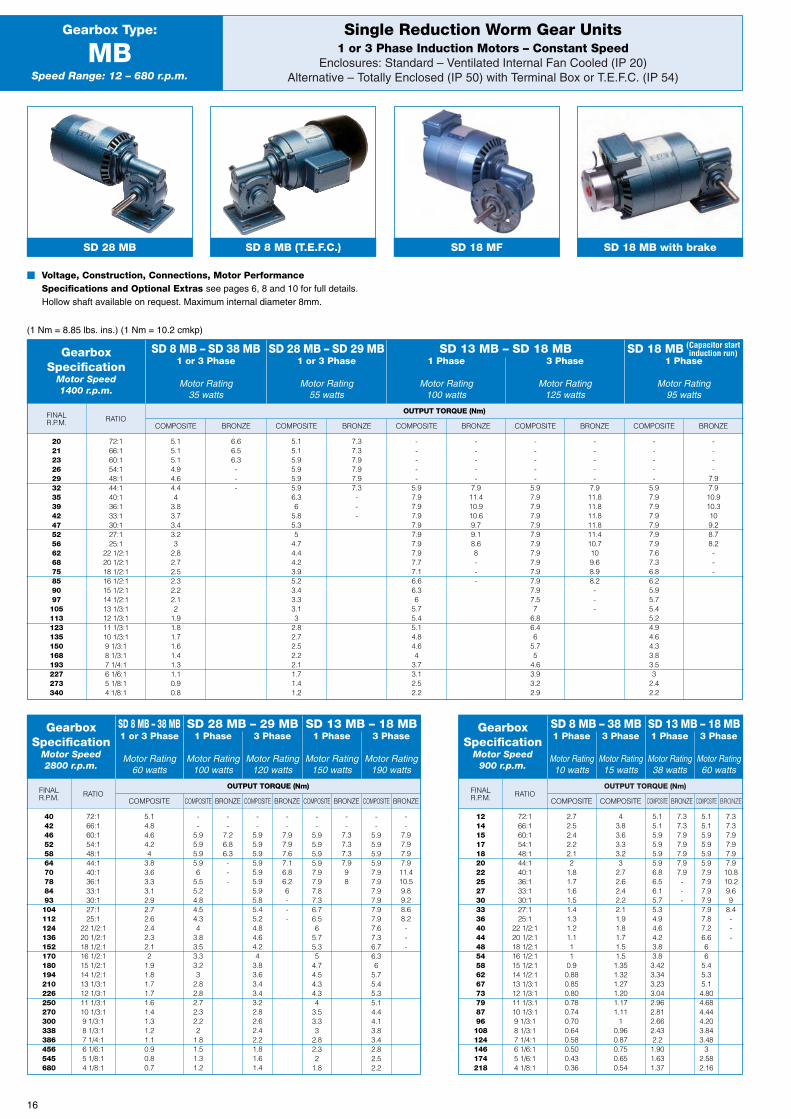
Single Reduction Worm Gear Units1 or 3 Phase Induction Motors – Constant Speed
Enclosures: Standard – Ventilated Internal Fan Cooled (IP 20)Alternative – Totally Enclosed (IP 50) with Terminal Box or T.E.F.C. (IP 54)
Gearbox Type:
MBSpeed Range: 12 – 680 r.p.m.
� Voltage, Construction, Connections, Motor PerformanceSpecifications and Optional Extras see pages 6, 8 and 10 for full details.Hollow shaft available on request. Maximum internal diameter 8mm.
(1 Nm = 8.85 lbs. ins.) (1 Nm = 10.2 cmkp)
GearboxSpecification
Motor Speed1400 r.p.m.
SD 28 MB – SD 29 MB1 or 3 Phase
Motor Rating55 watts
SD 18 MB1 Phase
Motor Rating95 watts
SD 8 MB – SD 38 MB1 or 3 Phase
Motor Rating35 watts
SD 13 MB – SD 18 MB1 Phase 3 Phase
Motor Rating Motor Rating100 watts 125 watts
202123262932353942475256626875859097105113123135150168193227273340
72:166:160:154:148:144:140:136:133:130:127:125:1
22 1/2:120 1/2:118 1/2:116 1/2:115 1/2:114 1/2:113 1/3:112 1/3:111 1/3:110 1/3:19 1/3:18 1/3:17 1/4:16 1/6:15 1/8:14 1/8:1
72:166:160:154:148:144:140:136:133:130:127:125:1
22 1/2:120 1/2:118 1/2:116 1/2:115 1/2:114 1/2:113 1/3:112 1/3:111 1/3:110 1/3:19 1/3:18 1/3:17 1/4:16 1/6:15 1/8:14 1/8:1
72:166:160:154:148:144:140:136:133:130:127:125:1
22 1/2:120 1/2:118 1/2:116 1/2:115 1/2:114 1/2:113 1/3:112 1/3:111 1/3:110 1/3:19 1/3:18 1/3:17 1/4:16 1/6:15 1/6:14 1/8:1
5.15.15.14.94.64.44
3.83.73.43.23
2.82.72.52.32.22.12
1.91.81.71.61.41.31.10.90.8
6.66.56.3---
5.14.84.64.24
3.83.63.33.12.92.72.62.42.32.12
1.91.81.71.71.61.41.31.21.10.90.80.7
2.72.52.42.22.12
1.81.71.61.51.41.31.21.111
0.90.880.850.800.780.740.700.640.580.500.430.36
43.83.63.33.23
2.72.62.42.22.11.91.81.71.51.51.351.321.271.201.171.11
10.960.870.750.650.54
5.15.15.95.95.95.96.86.56.15.75.34.94.64.23.83.83.423.343.233.042.962.812.662.432.21.901.631.37
7.37.37.97.97.97.97.9---
5.15.15.95.95.95.97.97.97.97.97.97.87.26.666
5.45.35.14.804.684.444.203.843.48
32.582.16
7.37.37.97.97.97.910.810.29.69
8.4---
5.15.15.95.95.95.96.36
5.85.35
4.74.44.23.95.23.43.33.13
2.82.72.52.22.11.71.41.2
7.37.37.97.97.97.3---
--
5.95.95.95.96
5.55.24.84.54.34
3.83.53.33.23
2.82.82.72.32.22
1.81.51.31.2
--
7.26.86.3---
-----
5.97.97.97.97.97.97.97.97.77.16.66.36
5.75.45.14.84.64
3.73.12.52.2
-----
7.911.410.910.69.79.18.68---
--
5.95.95.95.95.95.95.95.85.45.24.84.64.24
3.83.63.43.43.22.82.62.42.21.81.61.4
--
7.97.97.67.16.86.26---
-----
5.97.97.97.97.97.97.97.97.97.97.97.97.57
6.86.46
5.75
4.63.93.22.9
-----
7.911.811.811.811.811.410.7109.68.98.2---
--
7.37.37.37.998
-----
5.97.97.97.97.97.97.97.67.36.86.25.95.75.45.24.94.64.33.83.53
2.42.2
----
7.97.910.910.3109.28.78.2---
--
7.97.97.97.911.410.59.89.28.68.2---
GearboxSpecification
Motor Speed2800 r.p.m.
GearboxSpecification
Motor Speed900 r.p.m.
SD 8 MB – 38 MB1 or 3 Phase
Motor Rating60 watts
SD 28 MB – 29 MB1 Phase 3 Phase
Motor Rating Motor Rating100 watts 120 watts
SD 13 MB – 18 MB1 Phase 3 Phase
Motor Rating Motor Rating150 watts 190 watts
SD 8 MB – 38 MB1 Phase 3 Phase
Motor Rating Motor Rating10 watts 15 watts
SD 13 MB – 18 MB1 Phase 3 Phase
Motor Rating Motor Rating38 watts 60 watts
40424652586470788493104112124136152170180194210226250270300338386456545680
1214151718202225273033364044485458626773798796108124146174218
(Capacitor startinduction run)
SD 18 MB with brakeSD 18 MFSD 8 MB (T.E.F.C.)SD 28 MB
16
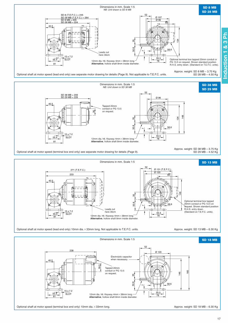
SD 8 MB = 205SD 28 MB = 224
Ø 96
52
134
7 58.6
3550
.8
7855.5SLOT
81
15 x 7.255.4
40.5
SD 8 (T.E.F.C.) = 245SD 28 MB (T.E.F.C.) = 264 Ø 107
80
SD 8 MBSD 28 MB
Dimensions in mm. Scale 1:5NB: Unit drawn is SD 8 MB
Optional shaft at motor speed (lead end only) see separate motor drawing for details (Page 9). Not applicable to T.E.F.C. units.Approx. weight: SD 8 MB – 3.70 Kg
SD 28 MB – 4.50 Kg
148
30SD 38 MB = 209SD 29 MB = 228 Ø 96
52
134
7 58.6
3550
.8
7855.5
SLOT
81
15 x 7.255.4
40.5
SD 38 MBSD 29 MB
Dimensions in mm. Scale 1:5NB: Unit drawn is SD 38 MB
Optional shaft at motor speed (terminal box end only) see separate motor drawing for details (Page 9).Approx. weight: SD 38 MB – 3.75 Kg
SD 29 MB – 4.52 Kg
233Ø 120
52
146
7 58.6
3550
.8
7855.5SLOT
81
15 x 7.255.4
40.5
Ø 131 (T.E.F.C.)271 (T.E.F.C.)
94
SD 13 MBDimensions in mm. Scale 1:5
Optional shaft at motor speed (lead end only) 10mm dia.�33mm long. Not applicable to T.E.F.C. units. Approx. weight: SD 13 MB – 6.30 Kg
160
39.5
238Ø 120
52
146
7 58.6
3550
.8
7855.5
SLOT81
15 x 7.255.4
40.5
SD 18 MBDimensions in mm. Scale 1:5
Optional shaft at motor speed (terminal box end only) 10mm dia.�33mm long. Approx. weight: SD 18 MB – 6.30 Kg
Leads outhere 30cm
12mm dia. h6. Keyway 4mm�38mm long.Alternative, hollow shaft 8mm inside diameter.
Tapped 20mmconduit or PG 13.5on request.
Tapped 20mmconduit or PG 13.5on request.
12mm dia. h6. Keyway 4mm�38mm long.Alternative, hollow shaft 8mm inside diameter.
12mm dia. h6. Keyway 4mm�38mm long.Alternative, hollow shaft 8mm inside diameter.
Electrolytic capacitorwhen necessary.
12mm dia. h6. Keyway 4mm�38mm long.Alternative, hollow shaft 8mm inside diameter.
Optional terminal box tapped 20mm conduit orPG 13.5 on request. Shown standard positionR.H.S. entry down. (Standard on T.E.F.C. units).
Leads outhere 30cm
Optional terminal box tapped20mm conduit or PG 13.5 onrequest. Shown standard positionR.H.S. entry down.(Standard on T.E.F.C. units).
17
Ind
uct
ion
1 &
3 P
h
BRONZE
OUTPUT TORQUE (Nm)FINALR.P.M. COMPOSITE COMPOSITE COMPOSITE COMPOSITE COMPOSITE COMPOSITEBRONZE BRONZEBRONZE BRONZE BRONZE
RATIO
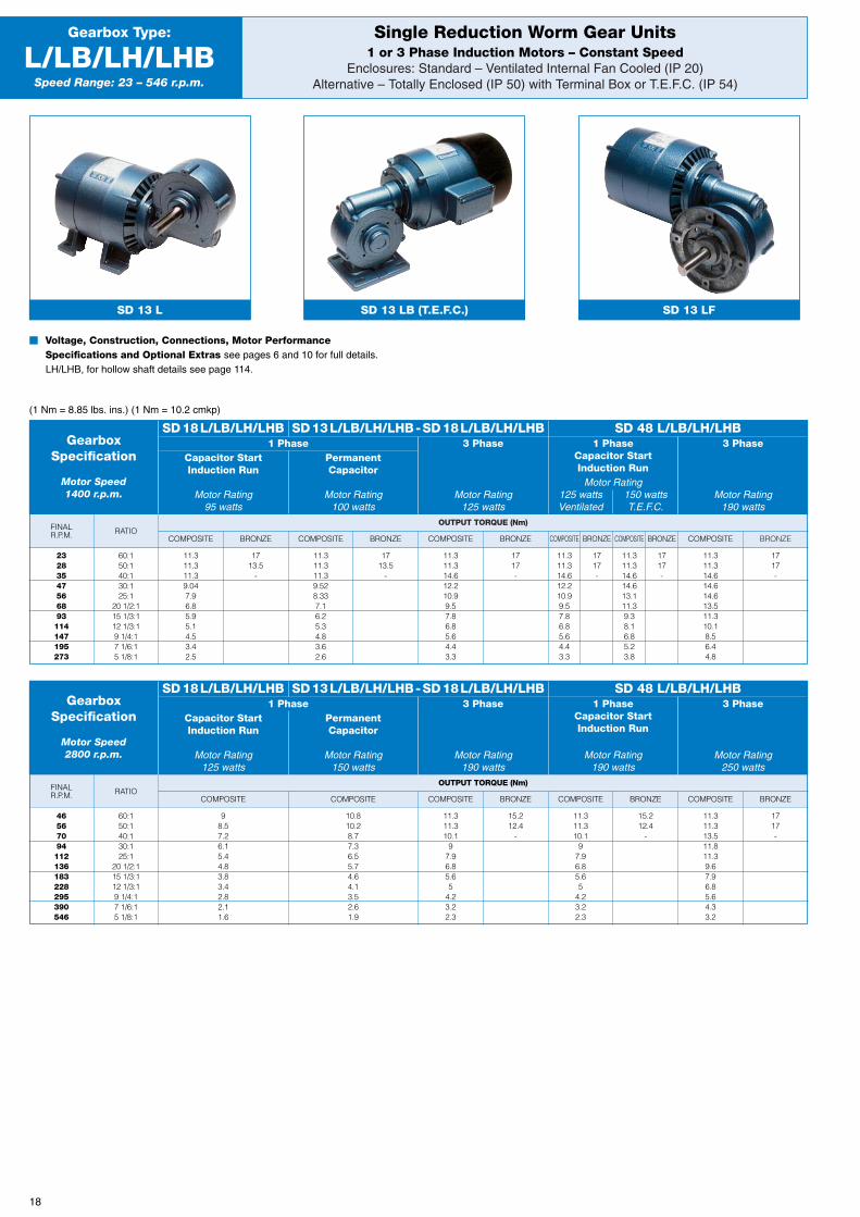
Single Reduction Worm Gear Units1 or 3 Phase Induction Motors – Constant Speed
Enclosures: Standard – Ventilated Internal Fan Cooled (IP 20)Alternative – Totally Enclosed (IP 50) with Terminal Box or T.E.F.C. (IP 54)
Gearbox Type:
L/LB/LH/LHBSpeed Range: 23 – 546 r.p.m.
(1 Nm = 8.85 lbs. ins.) (1 Nm = 10.2 cmkp)
GearboxSpecification
Motor Speed1400 r.p.m.
SD18L/LB/LH/LHB1 Phase 3 Phase
Motor Rating125 watts
PermanentCapacitor
Motor Rating100 watts
Capacitor StartInduction Run
Motor Rating95 watts
1 PhaseCapacitor StartInduction Run
Motor Rating125 watts 150 wattsVentilated T.E.F.C.
3 Phase
Motor Rating190 watts
SD13L/LB/LH/LHB-SD18L/LB/LH/LHB SD 48 L/LB/LH/LHB
23283547566893114147195273
60:150:140:130:125:1
20 1/2:115 1/3:112 1/3:19 1/4:17 1/6:15 1/8:1
11.311.311.39.047.96.85.95.14.53.42.5
1713.5
-
11.311.311.39.528.337.16.25.34.83.62.6
1713.5
-
11.311.314.612.210.99.57.86.85.64.43.3
1717-
11.311.314.612.210.99.57.86.85.64.43.3
1717-
11.311.314.614.613.111.39.38.16.85.23.8
1717-
11.311.314.614.614.613.511.310.18.56.44.8
1717-
BRONZE
OUTPUT TORQUE (Nm)FINALR.P.M. COMPOSITE COMPOSITE COMPOSITE COMPOSITE BRONZE COMPOSITEBRONZE
RATIO
GearboxSpecification
Motor Speed2800 r.p.m.
SD18L/LB/LH/LHB1 Phase 3 Phase
Motor Rating190 watts
PermanentCapacitor
Motor Rating150 watts
Capacitor StartInduction Run
Motor Rating125 watts
1 PhaseCapacitor StartInduction Run
Motor Rating190 watts
3 Phase
Motor Rating250 watts
SD13L/LB/LH/LHB-SD18L/LB/LH/LHB SD 48 L/LB/LH/LHB
46567094112136183228295390546
60:150:140:130:125:1
20 1/2:115 1/3:112 1/3:19 1/4:17 1/6:15 1/8:1
98.57.26.15.44.83.83.42.82.11.6
10.810.28.77.36.55.74.64.13.52.61.9
11.311.310.1
97.96.85.65
4.23.22.3
15.212.4
-
11.311.310.1
97.96.85.65
4.23.22.3
15.212.4
-
11.311.313.511.811.39.67.96.85.64.33.2
1717-
� Voltage, Construction, Connections, Motor PerformanceSpecifications and Optional Extras see pages 6 and 10 for full details.LH/LHB, for hollow shaft details see page 114.
SD 13 L SD 13 LB (T.E.F.C.) SD 13 LF
18
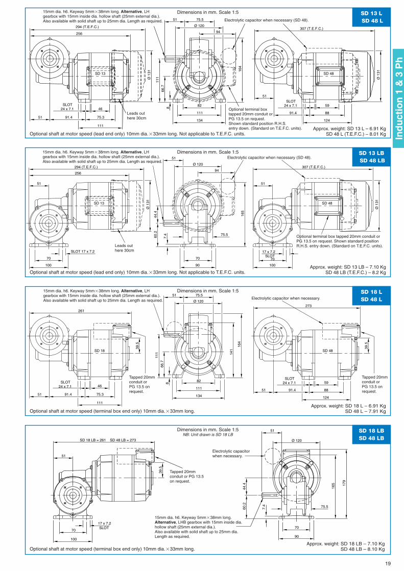
Ø 120
SD 13
256
75.5
51
51
Ø 1
31
294 (T.E.F.C.)94
8
111
75.3
46 SLOT24 x 7.1
134
111
82
66.7
91.4
111
164
Ø 1
31
307 (T.E.F.C.)
SD 48
51
88
124
91.4
SLOT24 x 7.1 59
SD 13 LSD 48 L
Dimensions in mm. Scale 1:5
Optional shaft at motor speed (lead end only) 10mm dia.�33mm long. Not applicable to T.E.F.C. units.Approx. weight: SD 13 L – 6.91 Kg
SD 48 L (T.E.F.C.) – 8.01 Kg
17 x 7.2 SLOT
51
70
100
75.5
60.2
70
90
7.4
44.4
165
51
70
SLOT 17 x 7.2
100
Ø 120
Ø 1
31
307 (T.E.F.C.)
SD 48SD 13
256
51
Ø 1
31
294 (T.E.F.C.)94
SD 13 LBSD 48 LB
Dimensions in mm. Scale 1:5
Optional shaft at motor speed (lead end only) 10mm dia.�33mm long. Not applicable to T.E.F.C. units.Approx. weight: SD 13 LB – 7.10 Kg
SD 48 LB (T.E.F.C.) – 8.2 Kg
51
39.5
39.5
Ø 120273
SD 48SD 18
261
75.5
51
51
141
88
124
91.4
SLOT24 x 7.1 598
111
75.3
46 SLOT24 x 7.1
134
111
82
66.7
91.4
111
164
SD 18 LSD 48 L
Dimensions in mm. Scale 1:5
Optional shaft at motor speed (terminal box end only) 10mm dia.�33mm long.Approx. weight: SD 18 L – 6.91 Kg
SD 48 L – 7.91 Kg
179
39.5
75.5
SD 18 LB = 261 SD 48 LB = 273 Ø 120
51
60.2
70
90
7.4
44.4
165
51
SLOT70
17 x 7.2
100
SD 18 LBSD 48 LB
Dimensions in mm. Scale 1:5NB: Unit drawn is SD 18 LB
Optional shaft at motor speed (terminal box end only) 10mm dia.�33mm long.Approx. weight: SD 18 LB – 7.10 Kg
SD 48 LB – 8.10 Kg
Leads outhere 30cm
Leads outhere 30cm
15mm dia. h6. Keyway 5mm�38mm long. Alternative, LHgearbox with 15mm inside dia. hollow shaft (25mm external dia.).Also available with solid shaft up to 25mm dia. Length as required.
15mm dia. h6. Keyway 5mm�38mm long. Alternative, LHgearbox with 15mm inside dia. hollow shaft (25mm external dia.).Also available with solid shaft up to 25mm dia. Length as required.
Tapped 20mmconduit or PG 13.5on request.
15mm dia. h6. Keyway 5mm�38mm long. Alternative, LHgearbox with 15mm inside dia. hollow shaft (25mm external dia.).Also available with solid shaft up to 25mm dia. Length as required.
Tapped 20mmconduit orPG 13.5 onrequest.
Tapped 20mmconduit orPG 13.5 onrequest.
Electrolytic capacitorwhen necessary.
15mm dia. h6. Keyway 5mm�38mm long.Alternative, LHB gearbox with 15mm inside dia.hollow shaft (25mm external dia.).Also available with solid shaft up to 25mm dia.Length as required.
Optional terminal boxtapped 20mm conduit orPG 13.5 on request.Shown standard position R.H.S.entry down. (Standard on T.E.F.C. units).
Optional terminal box tapped 20mm conduit orPG 13.5 on request. Shown standard positionR.H.S. entry down. (Standard on T.E.F.C. units).
Electrolytic capacitor when necessary (SD 48).
Electrolytic capacitor when necessary (SD 48).
Electrolytic capacitor when necessary.
19
Ind
uct
ion
1 &
3 P
h

BRONZE
OUTPUT TORQUE (Nm)FINALR.P.M. BRONZE
OUTPUT TORQUE (Nm)FINALR.P.M.
5.95.95.95.95.95.95.95.95.95.95.95.95.95.95.95.95.95.95.95.95.95.545.24.974.52
4444444444444444444444444
5.95.95.95.95.95.95.95.95.95.95.95.95.95.424.974.524.294.18
–––
44444444444444444444
3.883.763.543.393.14
2800:12376:11933:11800:11620:11440:1729:1479:1365:1287:1240:1209:1182:1160:1145:1129:1117:1112:1104:194:197:186:178:175:169:1
0.320.380.460.500.560.631.231.92.53.03.84.35.05.66.27.07.78.08.79.39.610.511.51213
5.95.95.95.95.95.95.95.95.95.95.95.95.95.95.95.95.95.95.95.95.95.95.95.95.9
4444444444444444444444444
5.95.95.95.95.95.95.95.95.95.95.95.95.95.95.95.95.95.95.95.95.95.95.95.95.9
4444444444444444444444444
5.95.95.95.95.95.95.95.95.95.95.95.95.95.95.95.95.95.95.95.95.95.95.75.424.88
4444444444444444444444444
5.95.95.95.95.95.95.95.95.95.95.95.24.754.29
–––
444444444444444
3.623.393.162.942.832.712.62.372.262.03
2800:12376:11933:11800:11620:11440:1729:1479:1365:1287:1240:1209:1182:1160:1145:1129:1117:1112:1104:194:191:186:178:175:169:1
11.21.51.61.8246810121416182022242628303234363840
BRONZE
FINALR.P.M.
OUTPUT TORQUE (Nm)
COMPOSITE COMPOSITE COMPOSITE COMPOSITE BRONZE COMPOSITE BRONZE COMPOSITE
COMPOSITE BRONZE COMPOSITE BRONZE COMPOSITE BRONZE COMPOSITE COMPOSITE BRONZE COMPOSITE
RATIO
RATIO RATIO
Double Reduction Worm Gear Units1 or 3 Phase Induction Motors – Constant Speed
Enclosures: Standard – Ventilated Internal Fan Cooled (IP 20)Alternative – Totally Enclosed (IP 50) with Terminal Box or T.E.F.C. (IP 54)
Gearbox Type:
SSSpeed Range: 0.32 – 40 r.p.m.
SD 41 SS SD 8 SS (T.E.F.C.) SD 38 SS
� Voltage, Construction, Connections, Motor PerformanceSpecifications and Optional Extras see pages 6 and 8 for full details.
(1 Nm = 8.85 lbs. ins.) (1 Nm = 10.2 cmkp )
GearboxSpecification
Motor Speed1400 r.p.m.
Shaded PoleTotally EnclosedMotor Rating
3.7 watts
Shaded PoleVentilated
Motor Rating8 watts
Capacitor
Motor Rating8 watts
1 or 3 Phase
Motor Rating10 watts
1 or 3 Phase
Motor Rating35 watts
1 or 3 Phase
Motor Rating55 watts
SD 41 SS SD 8 SS – SD 38 SS SD 28 SS – SD 29 SSSD 21 SS (1 Phase Only)
0.50.60.750.80.91234567891011121314151617181920242630
2800:12376:11933:11800:11620:11440:1729:1479:1365:1287:1240:1209:1182:1160:1145:1129:1117:1112:1104:194:191:186:178:175:169:158:153:147:1
44
3.42.92.72.52.262.031.811.581.361.241.191.131.071.020.960.900.850.790.730.680.620.570.510.450.400.34
44444444444
3.43.162.942.712.492.262.152.031.921.811.701.581.471.361.241.131.02
444444444444
3.162.942.712.492.262.152.031.921.811.701.581.471.361.241.131.02
44444444444444
3.623.282.942.832.712.492.372.262.031.921.811.581.471.36
5.95.95.95.95.95.95.95.95.95.95.655.094.52
–––
4444444444444444444444444444
5.95.95.95.95.95.95.95.95.95.95.95.95.95.95.95.95.95.95.95.95.95.95.85.545.274.754.223.96
4444444444444444444444444444
5.95.95.95.95.95.95.95.95.95.95.95.95.95.95.95.95.95.95.95.95.95.95.95.95.95.95.95.9
GearboxSpecification
Motor Speed2800 r.p.m.
GearboxSpecification
Motor Speed900 r.p.m.
1 or 3 Phase
Motor Rating25 watts
1 or 3 Phase
Motor Rating60 watts
1 Phase
Motor Rating100 watts
3 Phase
Motor Rating120 watts
SD 41 SS SD 8 SS – SD 38 SS SD 28 SS – SD 29 SS1 Phase
Motor Rating10 watts
3 Phase
Motor Rating15 watts
SD 8 SS – SD 38 SS
SD 8 SS with brake
20
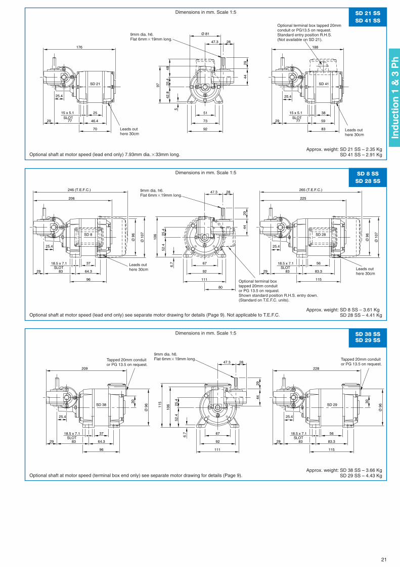
25.4
2929
2944
2847.3
SD 21 SD 41
188176
Ø 81
25.4 25.4
97
77
83
38
59
15 x 5.1SLOT
5
42.8
70
46.4
25SLOT
15 x 5.1
77
92
73
51
4825
.4
Ø 9
6
Ø 9
6
225
29
2944
2847.3
29
SD 28SD 8
206
Ø 1
07
Ø 1
07
265 (T.E.F.C.)246 (T.E.F.C.)
80
106
83 83.3
115
5618.5 x 7.1 SLOT
83
96
64.3
3718.5 x 7.1 SLOT 6.
7
111
92
67
52.425.4 25.4
3030
25.4
Ø 9
6
Ø 9
6
228
29
2944
2847.3
29
SD 29SD 38
209
115
106
83 83.3
115
5618.5 x 7.1 SLOT
83
96
64.3
3718.5 x 7.1 SLOT 6.
7
111
92
67
52.425.4 25.4
SD 21 SSSD 41 SS
SD 8 SSSD 28 SS
SD 38 SSSD 29 SS
Dimensions in mm. Scale 1:5
Dimensions in mm. Scale 1:5
Dimensions in mm. Scale 1:5
Optional shaft at motor speed (lead end only) 7.93mm dia.�33mm long.
Optional shaft at motor speed (lead end only) see separate motor drawing for details (Page 9). Not applicable to T.E.F.C.
Optional shaft at motor speed (terminal box end only) see separate motor drawing for details (Page 9).
Approx. weight: SD 21 SS – 2.35 KgSD 41 SS – 2.91 Kg
Approx. weight: SD 8 SS – 3.61 KgSD 28 SS – 4.41 Kg
Approx. weight: SD 38 SS – 3.66 KgSD 29 SS – 4.43 Kg
Leads outhere 30cm
Leads outhere 30cm
9mm dia. h6.Flat 6mm�19mm long.
Optional terminal box tapped 20mmconduit or PG13.5 on request. Standard entry position R.H.S.(Not available on SD 21).
Leads outhere 30cm
Tapped 20mm conduitor PG 13.5 on request.
Tapped 20mm conduitor PG 13.5 on request.
Leads outhere 30cm
9mm dia. h6.Flat 6mm�19mm long.
9mm dia. h6.Flat 6mm�19mm long.
Optional terminal boxtapped 20mm conduitor PG 13.5 on request.Shown standard position R.H.S. entry down.(Standard on T.E.F.C. units).
21
Ind
uct
ion
1 &
3 P
h
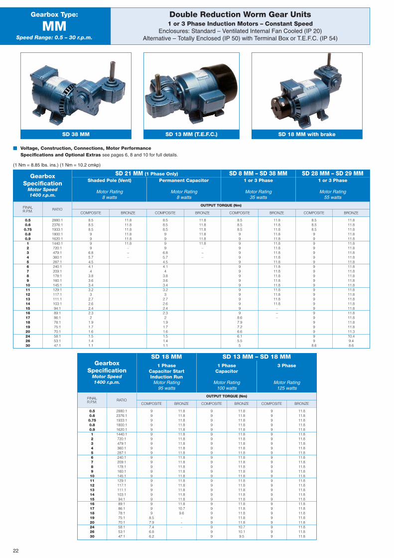
BRONZE
OUTPUT TORQUE (Nm)FINALR.P.M.
Double Reduction Worm Gear Units1 or 3 Phase Induction Motors – Constant Speed
Enclosures: Standard – Ventilated Internal Fan Cooled (IP 20)Alternative – Totally Enclosed (IP 50) with Terminal Box or T.E.F.C. (IP 54)
Gearbox Type:
MMSpeed Range: 0.5 – 30 r.p.m.
SD 38 MM
� Voltage, Construction, Connections, Motor PerformanceSpecifications and Optional Extras see pages 6, 8 and 10 for full details.
(1 Nm = 8.85 lbs. ins.) (1 Nm = 10.2 cmkp)
COMPOSITE BRONZE COMPOSITE BRONZE COMPOSITERATIO
GearboxSpecification
Motor Speed1400 r.p.m.
1 PhaseCapacitor StartInduction Run
Motor Rating95 watts
1 PhaseCapacitor
Motor Rating100 watts
3 Phase
Motor Rating125 watts
SD 18 MM SD 13 MM – SD 18 MM
0.50.60.750.80.91234567891011121314151617181920242630
2880:12376:11933:11800:11620:11440:1720:1479:1360:1287:1240:1209:1178:1160:1145:1129:1117:1111:1103:194:189:186:178:175:170:158:153:147:1
99999999999999999999999
8.57.97.46.86.2
11.811.811.811.811.811.811.811.811.811.811.811.811.811.811.811.811.811.811.811.811.810.79.6---
9999999999999999999999999999
11.811.811.811.811.811.811.811.811.811.811.811.811.811.811.811.811.811.811.811.811.811.811.811.811.810.710.19.5
9999999999999999999999999999
11.811.811.811.811.811.811.811.811.811.811.811.811.811.811.811.811.811.811.811.811.811.811.811.811.811.811.811.8
SD 18 MM with brakeSD 13 MM (T.E.F.C.)
BRONZE
OUTPUT TORQUE (Nm)FINALR.P.M. COMPOSITE BRONZE COMPOSITE BRONZE COMPOSITE BRONZE COMPOSITE
RATIO
GearboxSpecification
Motor Speed1400 r.p.m.
SD 21 MM (1 Phase Only) SD 8 MM – SD 38 MM SD 28 MM – SD 29 MMShaded Pole (Vent)
Motor Rating8 watts
Permanent Capacitor
Motor Rating8 watts
1 or 3 Phase
Motor Rating35 watts
1 or 3 Phase
Motor Rating55 watts
0.50.60.750.80.91234567891011121314151617181920242630
2880:12376:11933:11800:11620:11440:1720:1479:1360:1287:1240:1209:1178:1160:1145:1129:1117:1111:1103:194:189:186:178:175:170:158:153:147:1
8.58.58.59999
6.85.74.54.14
3.83.63.43.23
2.72.62.42.32
1.91.71.61.51.41.1
11.811.811.811.811.811.8
–––
8.58.58.59999
6.85.74.54.14
3.83.63.43.23
2.72.62.42.32
1.91.71.61.51.41.1
11.811.811.811.811.811.8
–––
8.58.58.5999999999999999999
8.67.97.26.66.15.55
11.811.811.811.811.811.811.811.811.811.811.811.811.811.811.811.811.811.811.8
–––
8.58.58.5999999999999999999999999
8.6
11.811.811.811.811.811.811.811.811.811.811.811.811.811.811.811.811.811.811.811.811.811.811.811.811.310.49.48.6
22
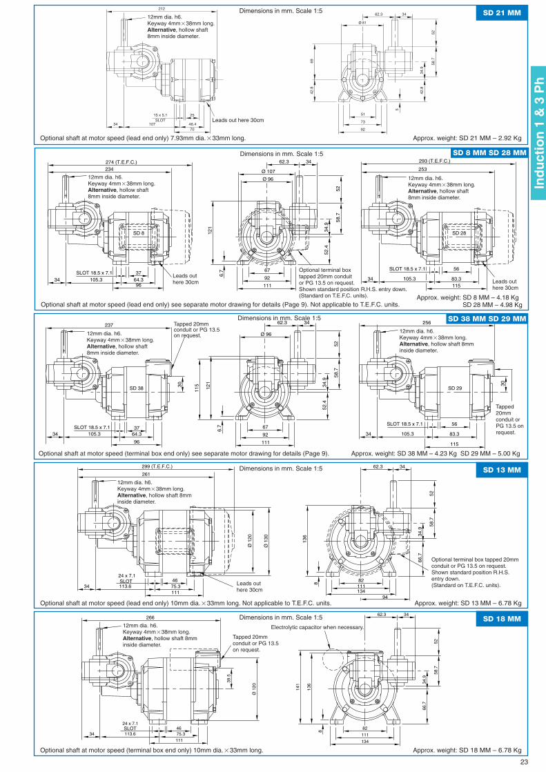
SD 28SD 8
253
34
234
Ø 96
34.9
5258
.7
3462.3
34SLOT 18.5 x 7.1
56
83.3
SLOT 18.5 x 7.1
105.311596
64.3
121
6.737
105.3111
92
67
52.4
293 (T.E.F.C.)274 (T.E.F.C.)
Ø 107
SD 8 MM SD 28 MMDimensions in mm. Scale 1:5
Optional shaft at motor speed (lead end only) see separate motor drawing for details (Page 9). Not applicable to T.E.F.C. units.Approx. weight: SD 8 MM – 4.18 Kg
SD 28 MM – 4.98 Kg
3030
256
SD 29SD 38
34
237
Ø 96
34.9
5258
.7
3462.3
34
115
SLOT 18.5 x 7.156
83.3
SLOT 18.5 x 7.1
105.3
11596
64.3
121
6.737
105.3
111
92
67
52.4
SD 38 MM SD 29 MMDimensions in mm. Scale 1:5
Optional shaft at motor speed (terminal box end only) see separate motor drawing for details (Page 9). Approx. weight: SD 38 MM – 4.23 Kg SD 29 MM – 5.00 Kg
Ø 1
20
261
34.9
5258
.7
3462.3
34
24 x 7.1 SLOT 8
11175.346
13411182
136
113.6
66.7
Ø 1
30
299 (T.E.F.C.)
94
SD 13 MMDimensions in mm. Scale 1:5
Optional shaft at motor speed (lead end only) 10mm dia.�33mm long. Not applicable to T.E.F.C. units. Approx. weight: SD 13 MM – 6.78 Kg
39.5
Ø 1
20
266
34.9
5258
.7
3462.3
34SLOT
141
24 x 7.1
8
11175.346
134
111
82
136
113.6
66.7
SD 18 MMDimensions in mm. Scale 1:5
Optional shaft at motor speed (terminal box end only) 10mm dia.�33mm long. Approx. weight: SD 18 MM – 6.78 Kg
Leads outhere 30cm Leads out
here 30cm
Leads outhere 30cm
12mm dia. h6.Keyway 4mm�38mm long.Alternative, hollow shaft8mm inside diameter.
12mm dia. h6.Keyway 4mm�38mm long.Alternative, hollow shaft8mm inside diameter.
Tapped 20mmconduit or PG 13.5on request.
Optional terminal box tapped 20mmconduit or PG 13.5 on request.Shown standard position R.H.S.entry down.(Standard on T.E.F.C. units).
12mm dia. h6.Keyway 4mm�38mm long.Alternative, hollow shaft8mm inside diameter.
12mm dia. h6.Keyway 4mm�38mm long.Alternative, hollow shaft 8mminside diameter.
Tapped20mmconduit orPG 13.5 onrequest.
Electrolytic capacitor when necessary.12mm dia. h6.Keyway 4mm�38mm long.Alternative, hollow shaft 8mminside diameter.
Ø 81
34.9
5258
.7
3462.3
34
212
5
7046.4
25SLOT
15 x 5.1
92
73
51
42.8
42.8
107
69
SD 21 MMDimensions in mm. Scale 1:5
Optional shaft at motor speed (lead end only) 7.93mm dia.�33mm long. Approx. weight: SD 21 MM – 2.92 Kg
12mm dia. h6.Keyway 4mm�38mm long.Alternative, hollow shaft8mm inside diameter.
12mm dia. h6.Keyway 4mm�38mm long.Alternative, hollow shaft 8mminside diameter.
Optional terminal boxtapped 20mm conduitor PG 13.5 on request. Shown standard position R.H.S. entry down.(Standard on T.E.F.C. units).
Tapped 20mmconduit or PG 13.5on request.
23
Ind
uct
ion
1 &
3 P
h
Leads out here 30cm
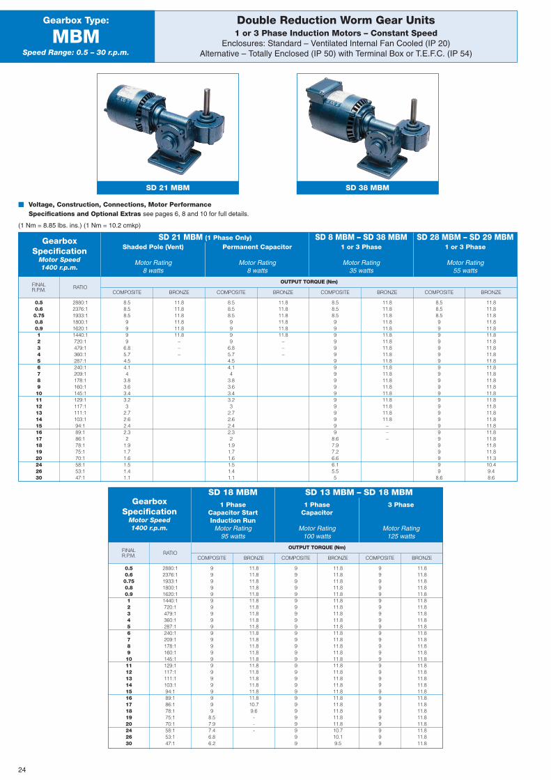
BRONZE
OUTPUT TORQUE (Nm)FINALR.P.M. COMPOSITE BRONZE COMPOSITE BRONZE COMPOSITE BRONZE COMPOSITE
RATIO
Double Reduction Worm Gear Units1 or 3 Phase Induction Motors – Constant Speed
Enclosures: Standard – Ventilated Internal Fan Cooled (IP 20)Alternative – Totally Enclosed (IP 50) with Terminal Box or T.E.F.C. (IP 54)
Gearbox Type:
MBMSpeed Range: 0.5 – 30 r.p.m.
� Voltage, Construction, Connections, Motor PerformanceSpecifications and Optional Extras see pages 6, 8 and 10 for full details.
(1 Nm = 8.85 lbs. ins.) (1 Nm = 10.2 cmkp)
GearboxSpecification
Motor Speed1400 r.p.m.
SD 21 MBM (1 Phase Only) SD 8 MBM – SD 38 MBM SD 28 MBM – SD 29 MBMShaded Pole (Vent)
Motor Rating8 watts
Permanent Capacitor
Motor Rating8 watts
1 or 3 Phase
Motor Rating35 watts
1 or 3 Phase
Motor Rating55 watts
0.50.60.750.80.91234567891011121314151617181920242630
2880:12376:11933:11800:11620:11440:1720:1479:1360:1287:1240:1209:1178:1160:1145:1129:1117:1111:1103:194:189:186:178:175:170:158:153:147:1
8.58.58.59999
6.85.74.54.14
3.83.63.43.23
2.72.62.42.32
1.91.71.61.51.41.1
11.811.811.811.811.811.8
–––
8.58.58.59999
6.85.74.54.14
3.83.63.43.23
2.72.62.42.32
1.91.71.61.51.41.1
11.811.811.811.811.811.8
–––
8.58.58.5999999999999999999
8.67.97.26.66.15.55
11.811.811.811.811.811.811.811.811.811.811.811.811.811.811.811.811.811.811.8
–––
8.58.58.5999999999999999999999999
8.6
11.811.811.811.811.811.811.811.811.811.811.811.811.811.811.811.811.811.811.811.811.811.811.811.811.310.49.48.6
BRONZE
OUTPUT TORQUE (Nm)FINALR.P.M. COMPOSITE BRONZE COMPOSITE BRONZE COMPOSITE
RATIO
GearboxSpecification
Motor Speed1400 r.p.m.
1 PhaseCapacitor StartInduction Run
Motor Rating95 watts
1 PhaseCapacitor
Motor Rating100 watts
3 Phase
Motor Rating125 watts
SD 18 MBM SD 13 MBM – SD 18 MBM
0.50.60.750.80.91234567891011121314151617181920242630
2880:12376:11933:11800:11620:11440:1720:1479:1360:1287:1240:1209:1178:1160:1145:1129:1117:1111:1103:194:189:186:178:175:170:158:153:147:1
99999999999999999999999
8.57.97.46.86.2
11.811.811.811.811.811.811.811.811.811.811.811.811.811.811.811.811.811.811.811.811.810.79.6---
9999999999999999999999999999
11.811.811.811.811.811.811.811.811.811.811.811.811.811.811.811.811.811.811.811.811.811.811.811.811.810.710.19.5
9999999999999999999999999999
11.811.811.811.811.811.811.811.811.811.811.811.811.811.811.811.811.811.811.811.811.811.811.811.811.811.811.811.8
SD 21 MBM SD 38 MBM
24
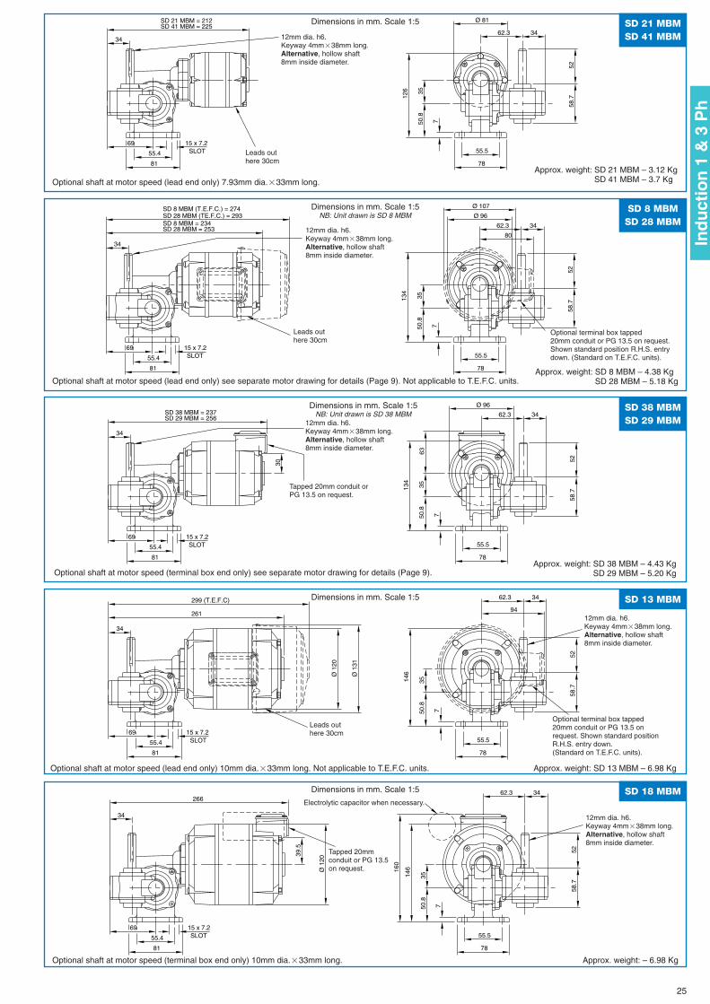
Ø 81
5258
.7
3462.3
126
69
7
3550
.8
78
55.5SLOT
81
15 x 7.2
55.4
34
SD 21 MBM = 212SD 41 MBM = 225 SD 21 MBM
SD 41 MBM
Dimensions in mm. Scale 1:5
Optional shaft at motor speed (lead end only) 7.93mm dia.�33mm long.
Approx. weight: SD 21 MBM – 3.12 KgSD 41 MBM – 3.7 Kg
SD 8 MBM = 234SD 28 MBM = 253
Ø 96
5258
.7
3462.3
134
69
7
3550
.8
78
55.5SLOT
81
15 x 7.2
55.4
34
SD 8 MBM (T.E.F.C.) = 274SD 28 MBM (TE.F.C.) = 293
Ø 107
80
SD 8 MBMSD 28 MBM
Dimensions in mm. Scale 1:5NB: Unit drawn is SD 8 MBM
Optional shaft at motor speed (lead end only) see separate motor drawing for details (Page 9). Not applicable to T.E.F.C. units.Approx. weight: SD 8 MBM – 4.38 Kg
SD 28 MBM – 5.18 Kg
63
30
SD 38 MBM = 237SD 29 MBM = 256
Ø 96
5258
.7
3462.3
134
69
7
3550
.8
78
55.5SLOT
81
15 x 7.2
55.4
34
SD 38 MBMSD 29 MBM
Dimensions in mm. Scale 1:5NB: Unit drawn is SD 38 MBM
Optional shaft at motor speed (terminal box end only) see separate motor drawing for details (Page 9). Approx. weight: SD 38 MBM – 4.43 Kg
SD 29 MBM – 5.20 Kg
Ø 1
20
261
5258
.7
3462.3
146
69
7
3550
.8
78
55.5SLOT
81
15 x 7.2
55.4
34
Ø 1
31
299 (T.E.F.C)
94
SD 13 MBMDimensions in mm. Scale 1:5
Optional shaft at motor speed (lead end only) 10mm dia.�33mm long. Not applicable to T.E.F.C. units. Approx. weight: SD 13 MBM – 6.98 Kg
39.5
160
Ø 1
20
266
5258
.7
3462.3
146
69
7
3550
.8
78
55.5SLOT
81
15 x 7.2
55.4
34
SD 18 MBMDimensions in mm. Scale 1:5
Optional shaft at motor speed (terminal box end only) 10mm dia.�33mm long. Approx. weight: – 6.98 Kg
Leads outhere 30cm
Leads outhere 30cm
12mm dia. h6.Keyway 4mm�38mm long.Alternative, hollow shaft8mm inside diameter.
12mm dia. h6.Keyway 4mm�38mm long.Alternative, hollow shaft8mm inside diameter.
12mm dia. h6.Keyway 4mm�38mm long.Alternative, hollow shaft8mm inside diameter.
12mm dia. h6.Keyway 4mm�38mm long.Alternative, hollow shaft8mm inside diameter.
12mm dia. h6.Keyway 4mm�38mm long.Alternative, hollow shaft8mm inside diameter.
Optional terminal box tapped20mm conduit or PG 13.5 on request.Shown standard position R.H.S. entrydown. (Standard on T.E.F.C. units).
Optional terminal box tapped20mm conduit or PG 13.5 onrequest. Shown standard positionR.H.S. entry down.(Standard on T.E.F.C. units).
Tapped 20mm conduit orPG 13.5 on request.
Leads outhere 30cm
Tapped 20mmconduit or PG 13.5on request.
Electrolytic capacitor when necessary.
25
Ind
uct
ion
1 &
3 P
h
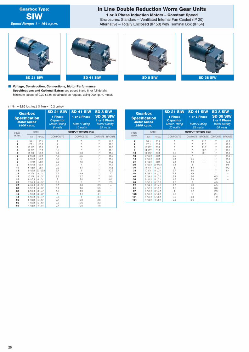
FINALR.P.M. BRONZE
OUTPUT TORQUE (Nm)
COMPOSITE COMPOSITE COMPOSITEINT
RATIO
FINAL
In Line Double Reduction Worm Gear Units1 or 3 Phase Induction Motors – Constant Speed
Enclosures: Standard – Ventilated Internal Fan Cooled (IP 20)Alternative – Totally Enclosed (IP 50) with Terminal Box (IP 54)
Gearbox Type:
SIWSpeed Range: 1 – 164 r.p.m.
SD 21 SIW SD 41 SIW SD 8 SIW SD 38 SIW
� Voltage, Construction, Connections, Motor PerformanceSpecifications and Optional Extras see pages 6 and 8 for full details.Minimum speed of 0,30 r.p.m. obtainable on request, using 900 r.p.m. motor.
(1 Nm = 8.85 lbs. ins.) (1 Nm = 10.2 cmkp)
GearboxSpecification
Motor Speed1400 r.p.m.
1 PhaseCapacitor
Motor Rating8 watts
1 or 3 Phase
Motor Rating10 watts
1 or 3 PhaseMotor Rating
35 watts
SD 21 SIW SD 41 SIW SD 8 SIW –SD 38 SIW
1234567891013151720232732364044526582
54:127:1
18 1/2:114 1/2:111 1/3:19 1/3:18 1/3:17 1/4:16 1/4:15 1/6:15 1/6:111 1/3:110 1/3:18 1/3:17 1/4:16 1/4:15 1/6:16 1/4:14 1/8:15 1/6:15 1/6:14 1/8:14 1/8:1
25:125:125:125:125:125:125:125:125:125:1
20 1/2:18 1/3:18 1/3:18 1/3:18 1/3:18 1/3:18 1/3:16 1/4:18 1/3:16 1/4:15 1/6:15 1/6:14 1/8:1
777
6.65.44.84.33.93.42.92.72.52.32
1.81.61.41.21
0.80.70.50.4
7777
6.35.55
4.54
3.43
2.92.72.42
1.81.61.31.11
0.80.60.5
777777777777777
6.35.54.84.13.42.82.31.8
11.311.311.311.311.311.311.311.311.311.310.9109.28.27.3–––
FINALR.P.M. BRONZE
OUTPUT TORQUE (Nm)
COMPOSITE COMPOSITE BRONZE COMPOSITEINT
RATIO
FINAL
GearboxSpecification
Motor Speed2800 r.p.m.
1 PhaseCapacitor
Motor Rating20 watts
1 or 3 Phase
Motor Rating25 watts
1 or 3 PhaseMotor Rating
60 watts
SD 21 SIW SD 41 SIW SD 8 SIW –SD 38 SIW
24681012142126303340465465728187105131164
54:127:1
18 1/2:114 1/2:111 1/3:19 1/3:18 1/3:15 1/6:15 1/6:111 1/3:110 1/3:18 1/3:17 1/4:16 1/4:15 1/6:16 1/4:14 1/8:15 1/6:15 1/6:14 1/8:14 1/8:1
25:125:125:125:125:125:125:125:1
20 1/2:18 1/3:18 1/3:18 1/3:18 1/3:18 1/3:18 1/3:16 1/4:18 1/3:16 1/4:15 1/6:15 1/6:14 1/8:1
7777
6.55.55.13.43.13
2.72.32.11.81.61.51.21
0.80.60.5
777777
6.54.34
3.83.62.92.62.32
1.81.61.21
0.80.6
11.311.311.39.78.1–––
777777777777
6.35.74.94.53.82.92.41.91.5
11.311.311.311.311.311.311.310.39.69.28.4–––
26
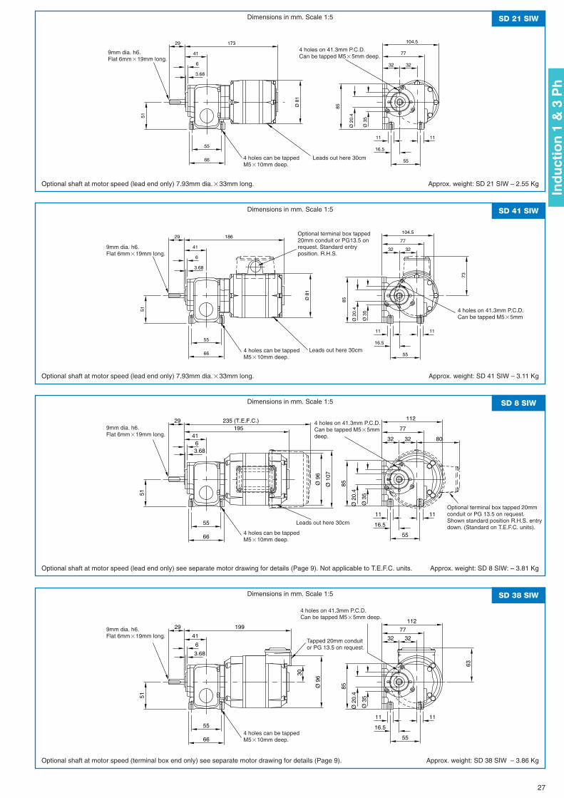
Ø 8
1
3232
77
104.5
41
6
3.68
85
Ø 2
0.4
Ø 3
5
66
5516.5
55
1111
17329
51
Ø 8
1
3232
77
104.5
41
6
3.68
85
Ø 2
0.4
Ø 3
5
66
5516.5
55
1111
18629
51
73
Ø 9
6
195
3232
77
112
4163.68
85
Ø 2
0.4
Ø 3
5
66
55 16.5
55
1111
29
51
Ø 1
07
235 (T.E.F.C.)
80
63
30
Ø 9
6
199
3232
77
112
41
6
3.68
85
Ø 2
0.4
Ø 3
5
66
55 16.5
55
1111
29
51
SD 21 SIW
SD 41 SIW
SD 8 SIW
SD 38 SIW
Dimensions in mm. Scale 1:5
Dimensions in mm. Scale 1:5
Dimensions in mm. Scale 1:5
Dimensions in mm. Scale 1:5
Optional shaft at motor speed (lead end only) 7.93mm dia.�33mm long.
Optional shaft at motor speed (lead end only) 7.93mm dia.�33mm long.
Optional shaft at motor speed (lead end only) see separate motor drawing for details (Page 9). Not applicable to T.E.F.C. units.
Optional shaft at motor speed (terminal box end only) see separate motor drawing for details (Page 9).
Approx. weight: SD 21 SIW – 2.55 Kg
Approx. weight: SD 41 SIW – 3.11 Kg
Approx. weight: SD 8 SIW: – 3.81 Kg
Approx. weight: SD 38 SIW – 3.86 Kg
9mm dia. h6.Flat 6mm�19mm long.
9mm dia. h6.Flat 6mm�19mm long.
4 holes can be tappedM5�10mm deep.
Leads out here 30cm
Leads out here 30cm
Leads out here 30cm
4 holes can be tappedM5�10mm deep.
4 holes can be tappedM5�10mm deep.
4 holes can be tappedM5�10mm deep.
4 holes on 41.3mm P.C.D.Can be tapped M5�5mm deep.
4 holes on 41.3mm P.C.D.Can be tapped M5�5mm
Optional terminal box tapped20mm conduit or PG13.5 onrequest. Standard entryposition. R.H.S.
4 holes on 41.3mm P.C.D.Can be tapped M5�5mmdeep.
Optional terminal box tapped 20mmconduit or PG 13.5 on request.Shown standard position R.H.S. entrydown. (Standard on T.E.F.C. units).
4 holes on 41.3mm P.C.D.Can be tapped M5�5mm deep.
Tapped 20mm conduitor PG 13.5 on request.
9mm dia. h6.Flat 6mm�19mm long.
9mm dia. h6.Flat 6mm�19mm long.
27
Ind
uct
ion
1 &
3 P
h
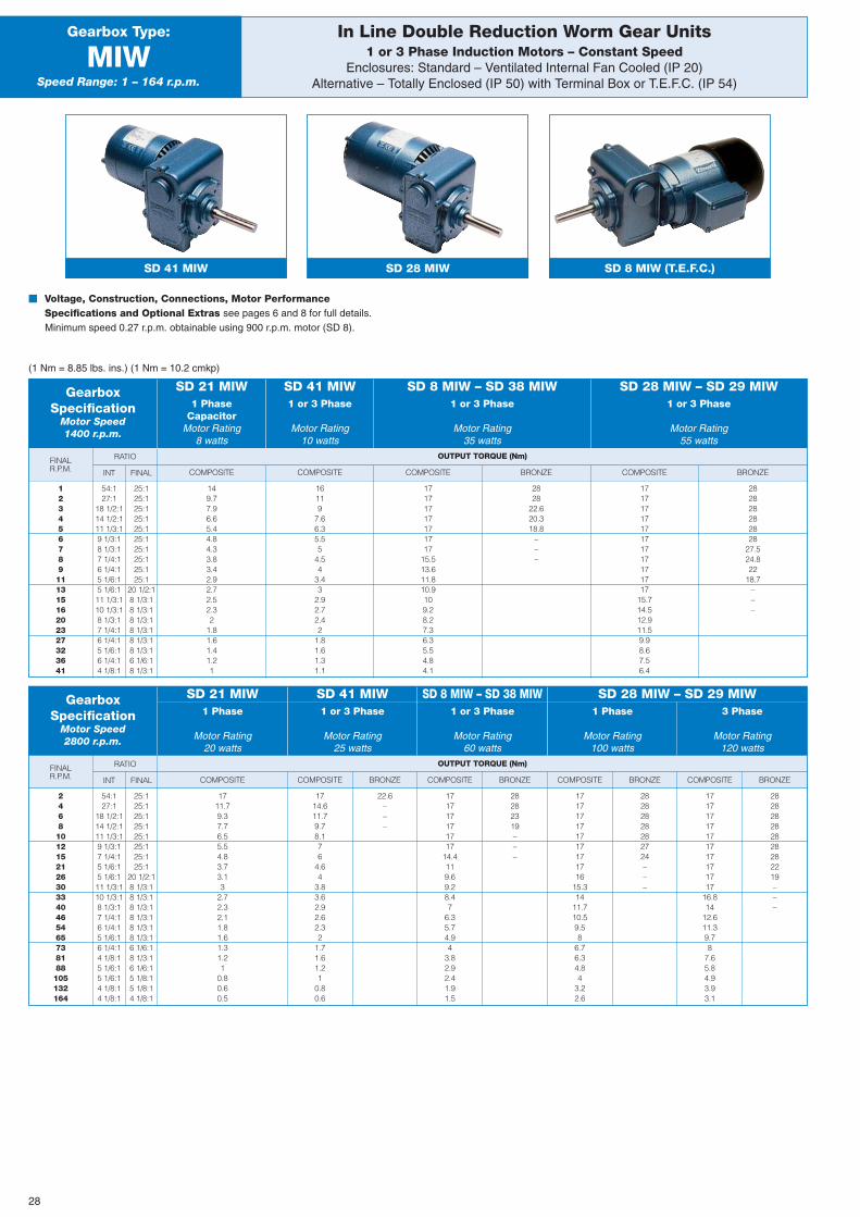
BRONZE
OUTPUT TORQUE (Nm)FINALR.P.M.
BRONZE
OUTPUT TORQUE (Nm)FINALR.P.M. COMPOSITE COMPOSITE COMPOSITE BRONZE COMPOSITE
RATIO
INT FINAL
In Line Double Reduction Worm Gear Units1 or 3 Phase Induction Motors – Constant Speed
Enclosures: Standard – Ventilated Internal Fan Cooled (IP 20)Alternative – Totally Enclosed (IP 50) with Terminal Box or T.E.F.C. (IP 54)
Gearbox Type:
MIWSpeed Range: 1 – 164 r.p.m.
SD 41 MIW SD 28 MIW SD 8 MIW (T.E.F.C.)
� Voltage, Construction, Connections, Motor PerformanceSpecifications and Optional Extras see pages 6 and 8 for full details.Minimum speed 0.27 r.p.m. obtainable using 900 r.p.m. motor (SD 8).
(1 Nm = 8.85 lbs. ins.) (1 Nm = 10.2 cmkp)
GearboxSpecification
Motor Speed1400 r.p.m.
1 PhaseCapacitor
Motor Rating8 watts
SD 21 MIW1 or 3 Phase
Motor Rating10 watts
SD 41 MIW1 or 3 Phase
Motor Rating35 watts
SD 8 MIW – SD 38 MIW1 or 3 Phase
Motor Rating55 watts
SD 28 MIW – SD 29 MIW
12345678911131516202327323641
54:127:1
18 1/2:114 1/2:111 1/3:19 1/3:18 1/3:17 1/4:16 1/4:15 1/6:15 1/6:111 1/3:110 1/3:18 1/3:17 1/4:16 1/4:15 1/6:16 1/4:14 1/8:1
25:125:125:125:125:125:125:125:125:125:1
20 1/2:18 1/3:18 1/3:18 1/3:18 1/3:18 1/3:18 1/3:16 1/6:18 1/3:1
149.77.96.65.44.84.33.83.42.92.72.52.32
1.81.61.41.21
16119
7.66.35.55
4.54
3.43
2.92.72.42
1.81.61.31.1
17171717171717
15.513.611.810.9109.28.27.36.35.54.84.1
2828
22.620.318.8
–––
1717171717171717171717
15.714.512.911.59.98.67.56.4
282828282828
27.524.822
18.7–––
COMPOSITE COMPOSITE BRONZE COMPOSITE BRONZE COMPOSITE BRONZE COMPOSITE
RATIO
INT FINAL
GearboxSpecification
Motor Speed2800 r.p.m.
1 Phase
Motor Rating20 watts
SD 21 MIW1 or 3 Phase
Motor Rating25 watts
SD 41 MIW1 or 3 Phase
Motor Rating60 watts
SD 8 MIW – SD 38 MIW1 Phase 3 Phase
Motor Rating Motor Rating100 watts 120 watts
SD 28 MIW – SD 29 MIW
24681012152126303340465465738188105132164
54:127:1
18 1/2:114 1/2:111 1/3:19 1/3:17 1/4:15 1/6:15 1/6:111 1/3:110 1/3:18 1/3:17 1/4:16 1/4:15 1/6:16 1/4:14 1/8:15 1/6:15 1/6:14 1/8:14 1/8:1
25:125:125:125:125:125:125:125:1
20 1/2:18 1/3:18 1/3:18 1/3:18 1/3:18 1/3:18 1/3:16 1/6:18 1/3:16 1/6:15 1/8:15 1/8:14 1/8:1
1711.79.37.76.55.54.83.73.13
2.72.32.11.81.61.31.21
0.80.60.5
1714.611.79.78.176
4.64
3.83.62.92.62.32
1.71.61.21
0.80.6
22.6–––
171717171717
14.4119.69.28.47
6.35.74.94
3.82.92.41.91.5
28282319–––
171717171717171716
15.314
11.710.59.58
6.76.34.84
3.22.6
28282828282724–––
17171717171717171717
16.814
12.611.39.78
7.65.84.93.93.1
282828282828282219–––
28
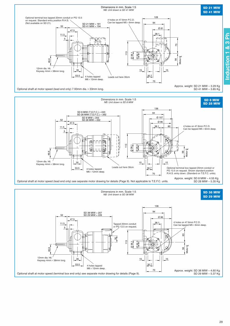
Ø 81
128
94
38.1
56
113
Ø 2
6.3
Ø 3
8.1
5
11.5
47.5
15
70
30.7
15
46.6
53.5
35
SD 21 MIW = 181SD 41 MIW = 19452
73
63
30
Ø 96
136
94
38.1
56
113
Ø 2
6.3
Ø 3
8.1
5
11.5
47.5
15
70
30.7
15
46.6
53.5
35
SD 38 MIW = 207SD 29 MIW = 22652
Ø 96
136
94
38.1
56
113
Ø 2
6.3
Ø 3
8.1
5
11.5
47.5
15
70
30.7
15
46.6
53.5
35
SD 8 MIW = 203SD 28 MIW = 22252
SD 8 MIW (T.E.F.C.) = 243SD 28 MIW (T.E.F.C.) = 262
Ø 107
80
SD 21 MIWSD 41 MIW
SD 38 MIWSD 29 MIW
SD 8 MIWSD 28 MIW
Dimensions in mm. Scale 1:5NB: Unit drawn is SD 41 MIW
Dimensions in mm. Scale 1:5NB: Unit drawn is SD 38 MIW
Dimensions in mm. Scale 1:5NB: Unit drawn is SD 8 MIW
Optional shaft at motor speed (lead end only) 7.93mm dia.�33mm long.
Optional shaft at motor speed (terminal box end only) see separate motor drawing for details (Page 9).
Optional shaft at motor speed (lead end only) see separate motor drawing for details (Page 9). Not applicable to T.E.F.C. units.
Approx. weight: SD 21 MIW – 3.29 KgSD 41 MIW – 3.85 Kg
Approx. weight: SD 38 MIW – 4.60 KgSD 29 MIW – 5.37 Kg
Approx. weight: SD 8 MIW – 4.55 KgSD 28 MIW – 5.35 Kg
Leads out here 30cm4 holes tappedM6�12mm deep.
4 holes tappedM6�12mm deep.
4 holes on 47.6mm P.C.D.Can be tapped M5�6mm deep.
Tapped 20mm conduitor PG 13.5 on request.
4 holes on 47.6mm P.C.D.Can be tapped M5�6mm deep.
4 holes on 47.6mm P.C.D.Can be tapped M5�6mm deep.
Optional terminal box tapped 20mm conduit or PG 13.5on request. Standard entry position R.H.S.(Not available on SD 21).
12mm dia. h6.Keyway 4mm�38mm long.
12mm dia. h6.Keyway 4mm�38mm long.
12mm dia. h6.Keyway 4mm�38mm long.
Optional terminal box tapped 20mm conduit orPG 13.5 on request. Shown standard positionR.H.S. entry down. (Standard on T.E.F.C. units).
Leads out here 30cm4 holes tappedM6�12mm deep.
29
Ind
uct
ion
1 &
3 P
h
Mot
or C L
Mot
or C L
Mot
or C L
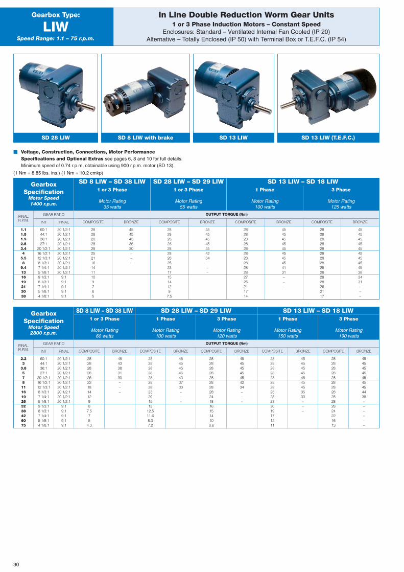
BRONZE
OUTPUT TORQUE (Nm)FINALR.P.M.
SD 28 LIW – SD 29 LIW SD 13 LIW – SD 18 LIW
BRONZE
OUTPUT TORQUE (Nm)FINALR.P.M. COMPOSITE BRONZE
GEAR RATIO
INT FINAL
In Line Double Reduction Worm Gear Units1 or 3 Phase Induction Motors – Constant Speed
Enclosures: Standard – Ventilated Internal Fan Cooled (IP 20)Alternative – Totally Enclosed (IP 50) with Terminal Box or T.E.F.C. (IP 54)
Gearbox Type:
LIWSpeed Range: 1.1 – 75 r.p.m.
SD 28 LIW SD 8 LIW with brake SD 13 LIW
� Voltage, Construction, Connections, Motor PerformanceSpecifications and Optional Extras see pages 6, 8 and 10 for full details.Minimum speed of 0.74 r.p.m. obtainable using 900 r.p.m. motor (SD 13).
(1 Nm = 8.85 lbs. ins.) (1 Nm = 10.2 cmkp)
GearboxSpecification
Motor Speed1400 r.p.m.
1 or 3 Phase
Motor Rating35 watts
1 or 3 Phase
Motor Rating55 watts
1 Phase
Motor Rating100 watts
3 Phase
Motor Rating125 watts
SD 8 LIW – SD 38 LIW SD 28 LIW – SD 29 LIW SD 13 LIW – SD 18 LIW
SD 13 LIW (T.E.F.C.)
1.11.51.92.53.44
5.58
9.4131619213038
60:144:136:127:1
20 1/2:116 1/2:112 1/3:18 1/3:17 1/4:15 1/8:19 1/3:18 1/3:17 1/4:15 1/8:14 1/8:1
20 1/2:120 1/2:120 1/2:120 1/2:120 1/2:120 1/2:120 1/2:120 1/2:120 1/2:120 1/2:1
9:19:19:19:19:1
28282828282521161411109765
4545433630–––
COMPOSITE BRONZE
282828282828282523171514129
7.5
45454545454234–––
COMPOSITE BRONZE
282828282828282828282725211714
45454545454545454131–––
COMPOSITE
282828282828282828282828262117
454545454545454545383431–––
COMPOSITE BRONZE COMPOSITE BRONZE COMPOSITE BRONZE COMPOSITE BRONZE COMPOSITE
GEAR RATIO
INT FINAL
GearboxSpecification
Motor Speed2800 r.p.m.
1 or 3 Phase
Motor Rating60 watts
1 Phase
Motor Rating100 watts
3 Phase
Motor Rating120 watts
1 Phase
Motor Rating150 watts
3 Phase
Motor Rating190 watts
SD 8 LIW – SD 38 LIW
2.23
3.8578111619263238426075
60:144:136:127:1
20 1/2:116 1/2:112 1/3:18 1/3:17 1/4:15 1/8:19 1/3:18 1/3:17 1/4:15 1/8:14 1/8:1
20 1/2:120 1/2:120 1/2:120 1/2:120 1/2:120 1/2:120 1/2:120 1/2:120 1/2:120 1/2:1
9:19:19:19:19:1
28282828262218141298
7.575
4.3
4543383130–––
2828282828282823201513
12.511.68.37.2
45454545433730–––
28282828282828282418161514108.6
45454545454234–––
282828282828282828232019171211
454545454545453530–––
282828282828282828282824221613
454545454545454438––––––
30
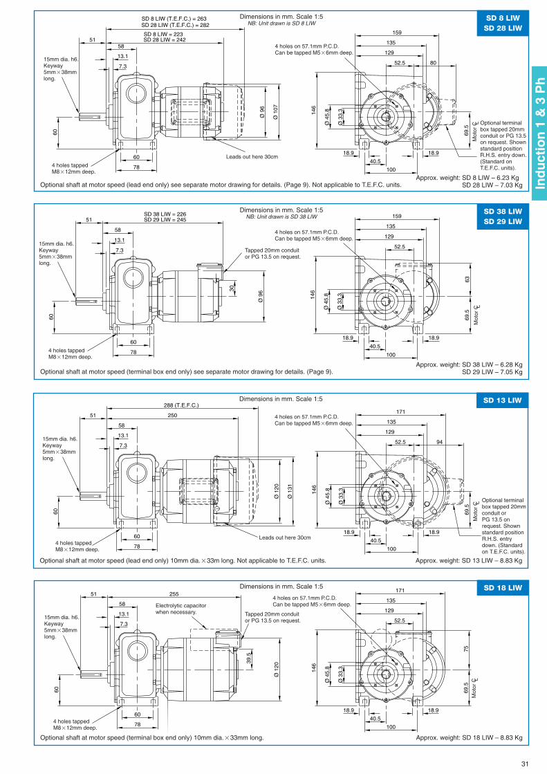
Ø 9
6
129
135
159
52.5
146
Ø 4
5.8
Ø 3
3.3
69.5
18.918.9
40.5
100
58
13.1
7.3
78
60
51
60
SD 8 LIW = 223SD 28 LIW = 242
Ø 1
07
SD 8 LIW (T.E.F.C.) = 263SD 28 LIW (T.E.F.C.) = 282
80
SD 8 LIWSD 28 LIW
Dimensions in mm. Scale 1:5NB: Unit drawn is SD 8 LIW
Optional shaft at motor speed (lead end only) see separate motor drawing for details. (Page 9). Not applicable to T.E.F.C. units.Approx. weight: SD 8 LIW – 6.23 Kg
SD 28 LIW – 7.03 Kg
Leads out here 30cm
4 holes tappedM8�12mm deep.
4 holes on 57.1mm P.C.D.Can be tapped M5�6mm deep.
15mm dia. h6.Keyway5mm�38mmlong.
Optional terminalbox tapped 20mmconduit or PG 13.5on request. Shownstandard positionR.H.S. entry down.(Standard onT.E.F.C. units).
63
30
Ø 9
6
129
135
159
52.5
146
Ø 4
5.8
Ø 3
3.3
69.5
18.918.9
40.5
100
58
13.1
7.3
78
60
51
60
SD 38 LIW = 226SD 29 LIW = 245
SD 38 LIWSD 29 LIW
Dimensions in mm. Scale 1:5NB: Unit drawn is SD 38 LIW
Optional shaft at motor speed (terminal box end only) see separate motor drawing for details. (Page 9). Approx. weight: SD 38 LIW – 6.28 Kg
SD 29 LIW – 7.05 Kg
4 holes tappedM8�12mm deep.
4 holes on 57.1mm P.C.D.Can be tapped M5�6mm deep.
Tapped 20mm conduitor PG 13.5 on request.
15mm dia. h6.Keyway5mm�38mmlong.
Ø 1
20
129
135
171
52.5
146
Ø 4
5.8
Ø 3
3.3
69.5
18.918.9
40.5
100
58
13.1
7.3
78
60
51
60
250
Ø 1
31
288 (T.E.F.C.)
94
SD 13 LIWDimensions in mm. Scale 1:5
Optional shaft at motor speed (lead end only) 10mm dia.�33m long. Not applicable to T.E.F.C. units. Approx. weight: SD 13 LIW – 8.83 Kg
4 holes tappedM8�12mm deep.
4 holes on 57.1mm P.C.D.Can be tapped M5�6mm deep.
15mm dia. h6.Keyway5mm�38mmlong.
Leads out here 30cm
Optional terminalbox tapped 20mmconduit orPG 13.5 onrequest. Shownstandard positionR.H.S. entrydown. (Standardon T.E.F.C. units).
Ø 1
20
75
39.5
129
135
171
52.5
146
Ø 4
5.8
Ø 3
3.3
69.5
18.918.9
40.5
100
58
13.1
7.3
78
60
51
60
255SD 18 LIWDimensions in mm. Scale 1:5
Optional shaft at motor speed (terminal box end only) 10mm dia.�33mm long. Approx. weight: SD 18 LIW – 8.83 Kg
4 holes tappedM8�12mm deep.
4 holes on 57.1mm P.C.D.Can be tapped M5�6mm deep.
15mm dia. h6.Keyway5mm�38mmlong.
Tapped 20mm conduitor PG 13.5 on request.
Electrolytic capacitorwhen necessary.
31
Ind
uct
ion
1 &
3 P
h
Mot
or C L
Mot
or C L
Mot
or C L
Mot
or C L
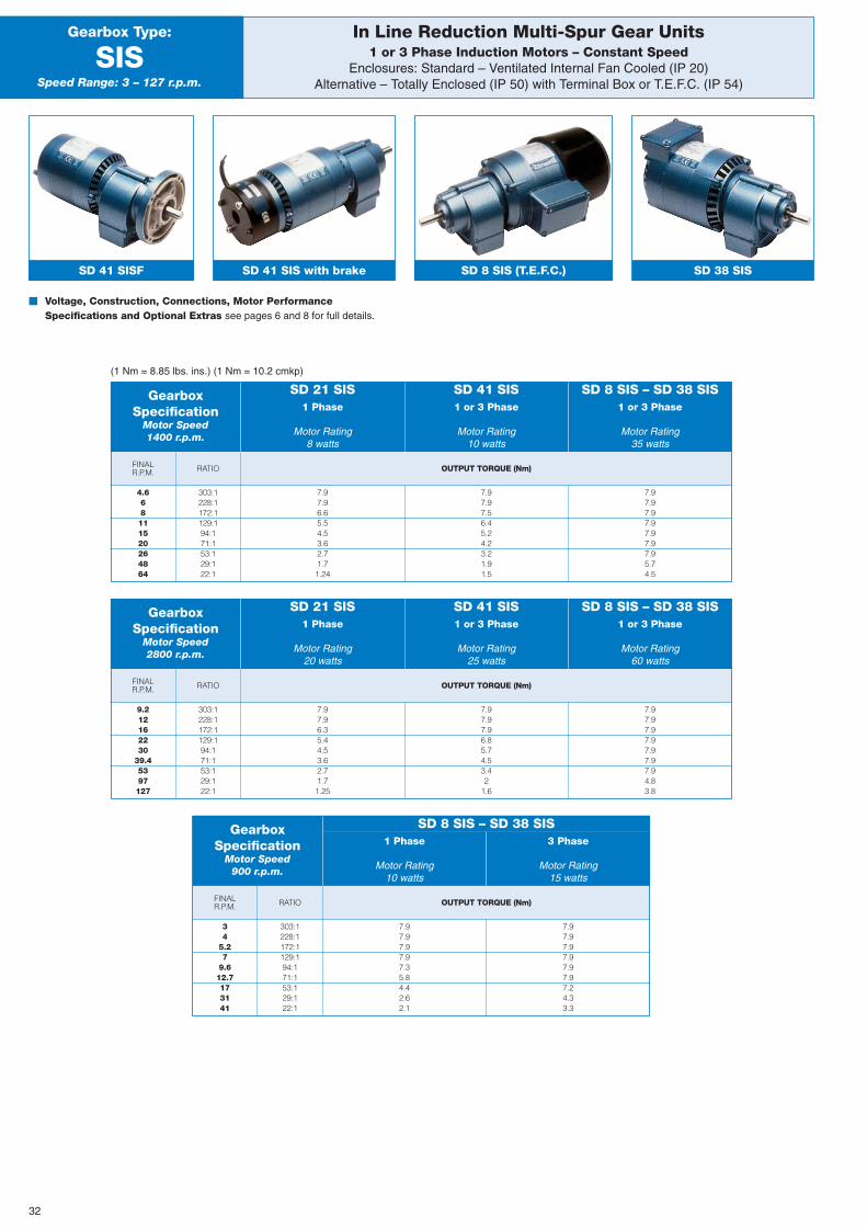
OUTPUT TORQUE (Nm)FINALR.P.M.
FINALR.P.M. OUTPUT TORQUE (Nm)RATIO
In Line Reduction Multi-Spur Gear Units1 or 3 Phase Induction Motors – Constant Speed
Enclosures: Standard – Ventilated Internal Fan Cooled (IP 20)Alternative – Totally Enclosed (IP 50) with Terminal Box or T.E.F.C. (IP 54)
Gearbox Type:
SISSpeed Range: 3 – 127 r.p.m.
SD 41 SISF SD 41 SIS with brake SD 8 SIS (T.E.F.C.)
� Voltage, Construction, Connections, Motor PerformanceSpecifications and Optional Extras see pages 6 and 8 for full details.
(1 Nm = 8.85 lbs. ins.) (1 Nm = 10.2 cmkp)
GearboxSpecification
Motor Speed1400 r.p.m.
1 Phase
Motor Rating8 watts
1 or 3 Phase
Motor Rating10 watts
1 or 3 Phase
Motor Rating35 watts
SD 21 SIS SD 41 SIS SD 8 SIS – SD 38 SIS
SD 38 SIS
4.668111520264864
303:1228:1172:1129:194:171:153:129:122:1
7.97.96.65.54.53.62.71.71.24
7.97.97.56.45.24.23.21.91.5
7.97.97.97.97.97.97.95.74.5
RATIO
GearboxSpecification
Motor Speed2800 r.p.m.
1 Phase
Motor Rating20 watts
1 or 3 Phase
Motor Rating25 watts
1 or 3 Phase
Motor Rating60 watts
SD 21 SIS SD 41 SIS SD 8 SIS – SD 38 SIS
9.212162230
39.45397127
303:1228:1172:1129:194:171:153:129:122:1
7.97.96.35.44.53.62.71.71.25
7.97.97.96.85.74.53.42
1.6
7.97.97.97.97.97.97.94.83.8
OUTPUT TORQUE (Nm)FINALR.P.M. RATIO
GearboxSpecification
Motor Speed900 r.p.m.
1 Phase
Motor Rating10 watts
3 Phase
Motor Rating15 watts
SD 8 SIS – SD 38 SIS
34
5.27
9.612.7173141
303:1228:1172:1129:194:171:153:129:122:1
7.97.97.97.97.35.84.42.62.1
7.97.97.97.97.97.97.24.33.3
32
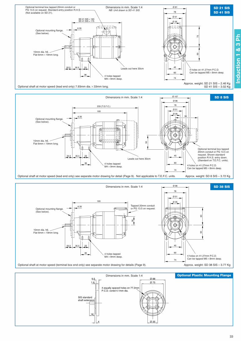
Ø 81
78
45
60
74
50
Ø 51
Ø 35
36
25.5 35.5 23
6.35
SD 21 SIS = 163SD 41 SIS = 175
73
63
30
193
Ø 96
78
45
60
74
50
Ø 51
Ø 35
36
25.5 35.5 23
6.35
193
Ø 96
78
45
60
74
50
Ø 51
Ø 35
36
25.5 35.5 23
6.35
233 (T.E.F.C.)
Ø 107
80
SD 21 SISSD 41 SIS
SD 38 SIS
SD 8 SIS
4
18
1.8
9.5
Ø 35
Ø 88
Ø 75
4 equally spaced holes on 77.2mmP.C.D. cored 4.1mm dia.
SIS standardshaft extension
Optional Plastic Mounting Flange
Dimensions in mm. Scale 1:4NB: Unit drawn is SD 41 SIS
Dimensions in mm. Scale 1:4
Dimensions in mm. Scale 1:4
Dimensions in mm. Scale 1:4
Optional shaft at motor speed (lead end only) 7.93mm dia.�33mm long.
Optional shaft at motor speed (terminal box end only) see separate motor drawing for details (Page 9).
Optional shaft at motor speed (lead end only) see separate motor drawing for detail (Page 9). Not applicable to T.E.F.C. units.
Approx. weight: SD 21 SIS – 2.46 KgSD 41 SIS – 3.02 Kg
Approx. weight: SD 38 SIS – 3.77 Kg
Approx. weight: SD 8 SIS – 3.72 Kg
Leads out here 30cm
4 holes tappedM4�9mm deep.
4 holes tappedM4�9mm deep.
4 holes on 41.27mm P.C.D.Can be tapped M5�8mm deep.
Tapped 20mm conduitor PG 13.5 on request.
4 holes on 41.27mm P.C.D.Can be tapped M5�8mm deep.
4 holes on 41.27mm P.C.D.Can be tapped M5�8mm deep.
10mm dia. h6.Flat 6mm�19mm long.
10mm dia. h6.Flat 6mm�19mm long.
10mm dia. h6.Flat 6mm�19mm long.
Optional mounting flange.(See below).
Optional mounting flange.(See below).
Optional mounting flange.(See below).
Optional terminal box tapped20mm conduit or PG 13.5 onrequest. Shown standardposition R.H.S. entry down.(Standard on T.E.F.C. units).
Optional terminal box tapped 20mm conduit orPG 13.5 on request. Standard entry position R.H.S.(Not available on SD 21).
Leads out here 30cm
4 holes tappedM4�9mm deep.
33
Ind
uct
ion
1 &
3 P
h
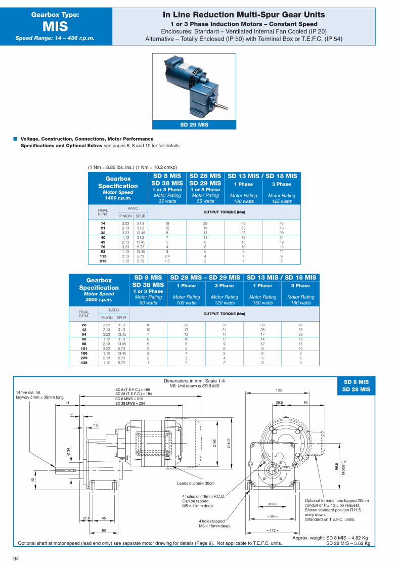
1 Phase
Motor Rating100 watts
3 Phase
Motor Rating125 watts
SD 13 MIS / SD 18 MIS
In Line Reduction Multi-Spur Gear Units1 or 3 Phase Induction Motors – Constant Speed
Enclosures: Standard – Ventilated Internal Fan Cooled (IP 20)Alternative – Totally Enclosed (IP 50) with Terminal Box or T.E.F.C. (IP 54)
Gearbox Type:
MISSpeed Range: 14 – 436 r.p.m.
FINALR.P.M. OUTPUT TORQUE (Nm)
PINION
RATIO
SPUR
SD 29 MIS
� Voltage, Construction, Connections, Motor PerformanceSpecifications and Optional Extras see pages 6, 8 and 10 for full details.
(1 Nm = 8.85 lbs. ins.) (1 Nm = 10.2 cmkp)
GearboxSpecification
Motor Speed1400 r.p.m.
1 or 3 PhaseMotor Rating
35 watts
1 or 3 PhaseMotor Rating
55 watts
SD 8 MISSD 38 MIS
SD 28 MISSD 29 MIS
14213240497693115218
3.232.133.231.122.133.231.122.131.12
31.331.313.4531.313.455.7313.455.735.73
181287543
2.41.3
2919131186542
453523191510874
4543292419131185
FINALR.P.M. OUTPUT TORQUE (Nm)
PINION
RATIO
SPUR
GearboxSpecification
Motor Speed2800 r.p.m.
1 or 3 PhaseMotor Rating
60 watts
1 Phase
Motor Rating100 watts
3 Phase
Motor Rating120 watts
SD 8 MISSD 38 MIS
SD 28 MIS – SD 29 MIS
2842648098151186229436
3.232.133.231.122.133.231.122.131.12
31.331.313.4531.313.455.7313.455.735.73
16107653321
2617121085432
3121141196542
39261714128653
453322181510864
Ø 9
6
96.8
28.5
27.6
SD 8 MWS = 215SD 28 MWS = 234
7
7.5
51
Ø 3
4
40
Ø 60
= 95 =
= 112 =60
45
133
Ø 1
07
SD 8 (T.E.F.C.) = 165SD 28 (T.E.F.C.) = 184
80
SD 8 MISSD 28 MIS
Dimensions in mm. Scale 1:4NB: Unit drawn is SD 8 MIS
Optional shaft at motor speed (lead end only) see separate motor drawing for details (Page 9). Not applicable to T.E.F.C. units.Approx. weight: SD 8 MIS – 4.82 Kg
SD 28 MIS – 5.62 Kg
Leads out here 30cm
Optional terminal box tapped 20mmconduit or PG 13.5 on request.Shown standard position R.H.S.entry down.(Standard on T.E.F.C. units). 4 holes tapped
M8�15mm deep.
4 holes on 48mm P.C.D.Can be tappedM5�11mm deep.
14mm dia. h6.keyway 5mm × 38mm long.
1 Phase
Motor Rating150 watts
3 Phase
Motor Rating190 watts
SD 13 MIS / SD 18 MIS
34
Mot
or C L
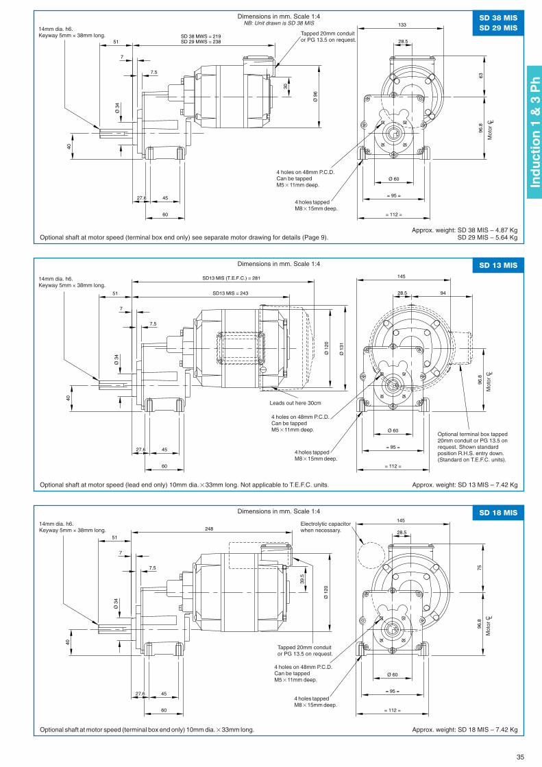
63
30
Ø 9
6
96.8
28.5
27.6
SD 38 MWS = 219SD 29 MWS = 238
7
7.5
51
Ø 3
4
40
Ø 60
= 95 =
= 112 =60
45
133
Dimensions in mm. Scale 1:4NB: Unit drawn is SD 38 MIS
248
75
39.5
Ø 1
20
96.8
28.5
27.6
7
7.5
51
Ø 3
4
40
Ø 60
= 95 =
= 112 =60
45
145SD 18 MISDimensions in mm. Scale 1:4
Optional shaft at motor speed (terminal box end only) see separate motor drawing for details (Page 9).
Optional shaft at motor speed (terminal box end only) 10mm dia.�33mm long. Approx. weight: SD 18 MIS – 7.42 Kg
Ø 1
20
96.8
28.5
27.6
SD13 MIS = 243
7
7.5
51
Ø 3
4
40
Ø 60
= 95 =
= 112 =60
45
145
Ø 1
31
SD13 MIS (T.E.F.C.) = 281
94
SD 13 MISDimensions in mm. Scale 1:4
Optional shaft at motor speed (lead end only) 10mm dia.�33mm long. Not applicable to T.E.F.C. units. Approx. weight: SD 13 MIS – 7.42 Kg
SD 38 MISSD 29 MIS
Approx. weight: SD 38 MIS – 4.87 KgSD 29 MIS – 5.64 Kg
4 holes tappedM8�15mm deep.
4 holes tappedM8�15mm deep.
4 holes on 48mm P.C.D.Can be tappedM5�11mm deep.
4 holes on 48mm P.C.D.Can be tappedM5�11mm deep.
Tapped 20mm conduitor PG 13.5 on request.
14mm dia. h6.Keyway 5mm × 38mm long.
14mm dia. h6.Keyway 5mm × 38mm long.
4 holes tappedM8�15mm deep.
4 holes on 48mm P.C.D.Can be tappedM5�11mm deep.
Tapped 20mm conduitor PG 13.5 on request.
Electrolytic capacitorwhen necessary.
14mm dia. h6.Keyway 5mm × 38mm long.
Leads out here 30cm
Optional terminal box tapped20mm conduit or PG 13.5 onrequest. Shown standardposition R.H.S. entry down.(Standard on T.E.F.C. units).
35
Ind
uct
ion
1 &
3 P
h
Mot
or C L
Mot
or C L
Mot
or C L
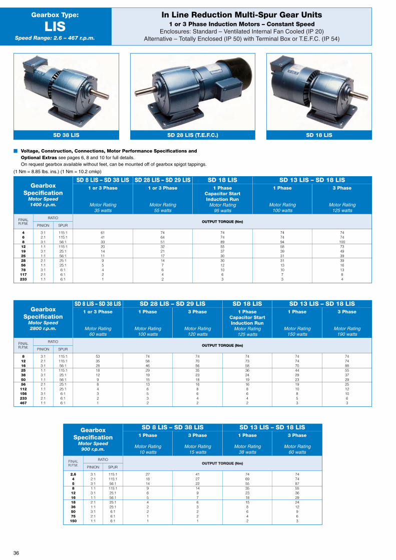
OUTPUT TORQUE (Nm)FINALR.P.M.
OUTPUT TORQUE (Nm)FINALR.P.M.
FINALR.P.M. OUTPUT TORQUE (Nm)
RATIO
PINION SPUR
In Line Reduction Multi-Spur Gear Units1 or 3 Phase Induction Motors – Constant Speed
Enclosures: Standard – Ventilated Internal Fan Cooled (IP 20)Alternative – Totally Enclosed (IP 50) with Terminal Box or T.E.F.C. (IP 54)
Gearbox Type:
LISSpeed Range: 2.6 – 467 r.p.m.
SD 38 LIS SD 28 LIS (T.E.F.C.) SD 18 LIS
� Voltage, Construction, Connections, Motor Performance Specifications andOptional Extras see pages 6, 8 and 10 for full details.On request gearbox available without feet, can be mounted off of gearbox spigot tappings.
(1 Nm = 8.85 lbs. ins.) (1 Nm = 10.2 cmkp)
GearboxSpecification
Motor Speed1400 r.p.m.
1 or 3 Phase
Motor Rating35 watts
1 or 3 Phase
Motor Rating55 watts
1 PhaseCapacitor StartInduction Run
Motor Rating95 watts
1 Phase
Motor Rating100 watts
3 Phase
Motor Rating125 watts
SD 8 LIS – SD 38 LIS SD 28 LIS – SD 29 LIS SD 18 LIS SD 13 LIS – SD 18 LIS
468121925285678117233
3:12:13:11:13:11:12:11:13:12:11:1
115:1115:156:1115:125:156:125:125:16:16:16:1
61413320141195421
746451322117147642
74748955373030121063
74749458393131131073
747410073493939161384
RATIO
PINION SPUR
GearboxSpecification
Motor Speed2800 r.p.m.
1 or 3 Phase
Motor Rating60 watts
1 Phase
Motor Rating100 watts
3 Phase
Motor Rating120 watts
1 PhaseCapacitor StartInduction Run
Motor Rating125 watts
1 Phase
Motor Rating150 watts
3 Phase
Motor Rating190 watts
SD 8 LIS – SD 38 LIS SD 28 LIS – SD 29 LIS SD 18 LIS SD 13 LIS – SD 18 LIS
8121625385056112156233467
3:12:13:11:13:11:12:11:13:12:11:1
115:1115:156:1115:125:156:125:125:16:16:16:1
5335281812984321
745846291915136532
747056352318168642
747358362419168642
7474704429231910853
74748855372925121063
RATIO
PINION SPUR
GearboxSpecification
Motor Speed900 r.p.m.
1 Phase
Motor Rating10 watts
3 Phase
Motor Rating15 watts
1 Phase
Motor Rating38 watts
3 Phase
Motor Rating60 watts
SD 8 LIS – SD 38 LIS SD 13 LIS – SD 18 LIS
2.6458121618365075150
3:12:13:11:13:11:12:11:13:12:11:1
115:1115:156:1115:125:156:125:125:16:16:16:1
27181496542211
412722149763221
746955352318158642
7474875536292412963
36
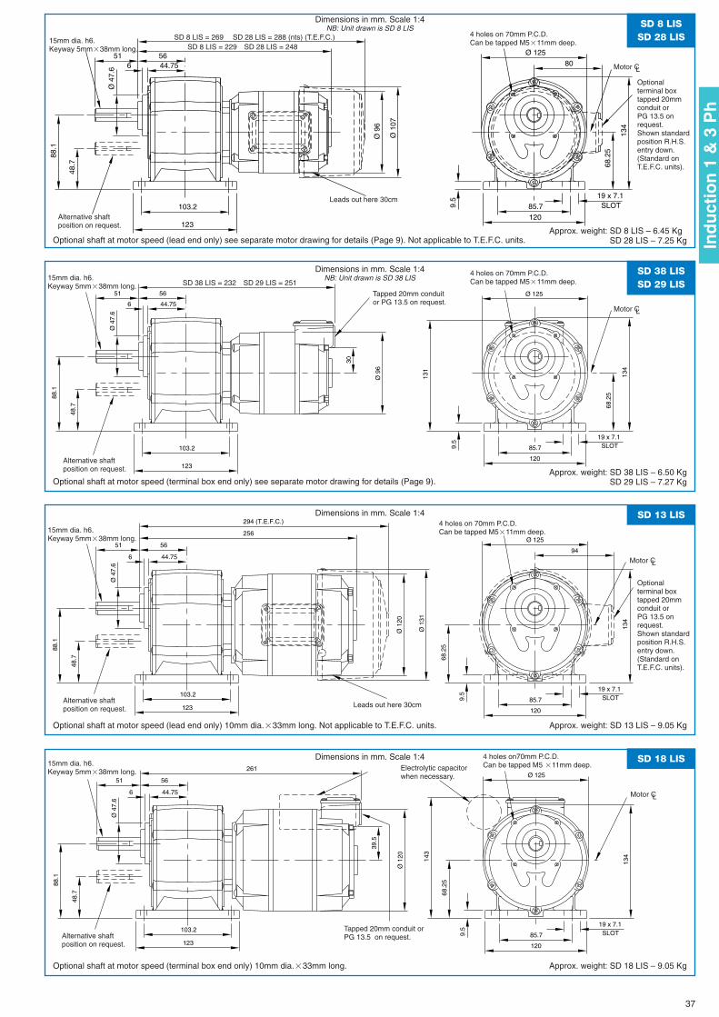
Ø 9
6
6 44.755651
Ø 4
7.6
Ø 125
48.7
88.1
103.2
123
134
68.2
5
9.5
SLOT19 x 7.1
12085.7
Ø 1
07
80
SD 8 LISSD 28 LIS
Dimensions in mm. Scale 1:4NB: Unit drawn is SD 8 LIS
Optional shaft at motor speed (lead end only) see separate motor drawing for details (Page 9). Not applicable to T.E.F.C. units.Approx. weight: SD 8 LIS – 6.45 Kg
SD 28 LIS – 7.25 Kg
Leads out here 30cm
Alternative shaftposition on request.
4 holes on 70mm P.C.D.Can be tapped M5�11mm deep.
Motor CL
Motor CL
Motor CL
Motor CL
15mm dia. h6.Keyway 5mm�38mm long.
SD 8 LIS = 269 SD 28 LIS = 288 (nts) (T.E.F.C.)SD 8 LIS = 229 SD 28 LIS = 248
30
Ø 9
6
6 44.75
5651
Ø 4
7.6
Ø 125
131
48.7
88.1
103.2
123
134
68.2
5
9.5
SLOT19 x 7.1
120
85.7
SD 38 LISSD 29 LIS
Dimensions in mm. Scale 1:4NB: Unit drawn is SD 38 LIS
Optional shaft at motor speed (terminal box end only) see separate motor drawing for details (Page 9). Approx. weight: SD 38 LIS – 6.50 Kg
SD 29 LIS – 7.27 Kg
Tapped 20mm conduitor PG 13.5 on request.
Alternative shaftposition on request.
4 holes on 70mm P.C.D.Can be tapped M5�11mm deep.15mm dia. h6.
Keyway 5mm�38mm long. SD 38 LIS = 232 SD 29 LIS = 251
Ø 1
20
256
6 44.75
5651
Ø 4
7.6
Ø 125
48.7
88.1
103.2
123
134
68.2
5
9.5
SLOT19 x 7.1
120
85.7
Ø 1
31
294 (T.E.F.C.)
94
SD 13 LISDimensions in mm. Scale 1:4
Optional shaft at motor speed (lead end only) 10mm dia.�33mm long. Not applicable to T.E.F.C. units. Approx. weight: SD 13 LIS – 9.05 Kg
Leads out here 30cmAlternative shaftposition on request.
4 holes on 70mm P.C.D.Can be tapped M5�11mm deep.15mm dia. h6.
Keyway 5mm�38mm long.
39.5
Ø 1
20
261
6 44.75
5651
Ø 4
7.6
Ø 125
143
48.7
88.1
103.2
123
134
68.2
5
9.5
SLOT19 x 7.1
120
85.7
SD 18 LISDimensions in mm. Scale 1:4
Optional shaft at motor speed (terminal box end only) 10mm dia.�33mm long. Approx. weight: SD 18 LIS – 9.05 Kg
Tapped 20mm conduit orPG 13.5 on request.Alternative shaft
position on request.
4 holes on70mm P.C.D.Can be tapped M5 �11mm deep.15mm dia. h6.
Keyway 5mm�38mm long. Electrolytic capacitorwhen necessary.
37
Optionalterminal boxtapped 20mmconduit orPG 13.5 onrequest.Shown standardposition R.H.S.entry down.(Standard onT.E.F.C. units).
Optionalterminal boxtapped 20mmconduit orPG 13.5 onrequest.Shown standardposition R.H.S.entry down.(Standard onT.E.F.C. units).
Ind
uct
ion
1 &
3 P
h
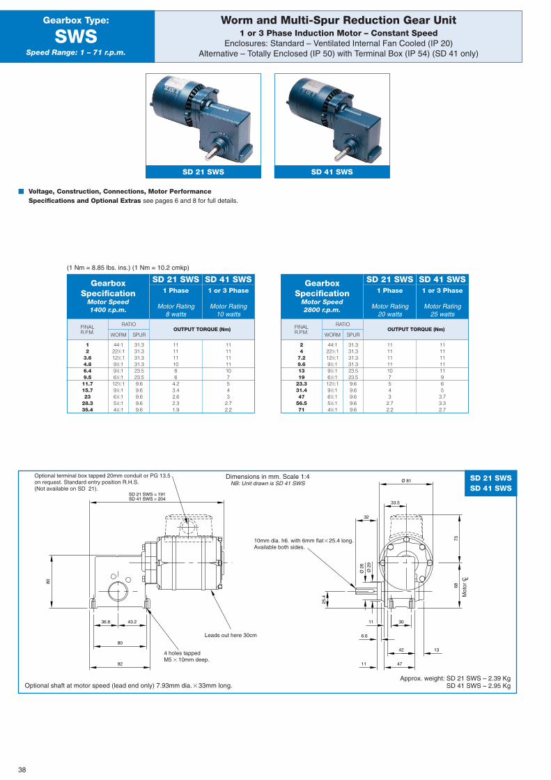
Worm and Multi-Spur Reduction Gear Unit1 or 3 Phase Induction Motor – Constant Speed
Enclosures: Standard – Ventilated Internal Fan Cooled (IP 20)Alternative – Totally Enclosed (IP 50) with Terminal Box (IP 54) (SD 41 only)
Gearbox Type:
SWSSpeed Range: 1 – 71 r.p.m.
FINALR.P.M. OUTPUT TORQUE (Nm)
WORM
RATIO
SPUR
SD 21 SWS SD 41 SWS
� Voltage, Construction, Connections, Motor PerformanceSpecifications and Optional Extras see pages 6 and 8 for full details.
(1 Nm = 8.85 lbs. ins.) (1 Nm = 10.2 cmkp)
GearboxSpecification
Motor Speed1400 r.p.m.
1 Phase
Motor Rating8 watts
1 or 3 Phase
Motor Rating10 watts
SD 21 SWS SD 41 SWS
12
3.64.86.49.511.715.723
28.335.4
44:1221⁄2:1121⁄2:191⁄3:191⁄3:161⁄4:1121⁄2:191⁄3:161⁄4:151⁄6:141⁄8:1
31.331.331.331.323.523.59.69.69.69.69.6
1111111086
4.23.42.62.31.9
11111111107543
2.72.2
FINALR.P.M. OUTPUT TORQUE (Nm)
WORM
RATIO
SPUR
GearboxSpecification
Motor Speed2800 r.p.m.
1 Phase
Motor Rating20 watts
1 or 3 Phase
Motor Rating25 watts
SD 21 SWS SD 41 SWS
24
7.29.61319
23.331.447
56.571
44:1221⁄2:1121⁄2:191⁄3:191⁄3:161⁄3:1121⁄2:191⁄3:161⁄4:151⁄6:141⁄8:1
31.331.331.331.323.523.59.69.69.69.69.6
11111111107543
2.72.2
1111111111965
3.73.32.7
38
SD 21 SWS = 191SD 41 SWS = 204
Ø 81
25.4
Ø 2
9
Ø 2
6
32
33.5
6.6
1342
11 47
11 30
68
43.236.8
80
80
92
73
SD 21 SWSSD 41 SWS
Dimensions in mm. Scale 1:4NB: Unit drawn is SD 41 SWS
Optional shaft at motor speed (lead end only) 7.93mm dia.�33mm long.Approx. weight: SD 21 SWS – 2.39 Kg
SD 41 SWS – 2.95 Kg
4 holes tappedM5�10mm deep.
10mm dia. h6. with 6mm flat�25.4 long.Available both sides.
Optional terminal box tapped 20mm conduit or PG 13.5on request. Standard entry position R.H.S.(Not available on SD 21).
Leads out here 30cm
Mot
or C L
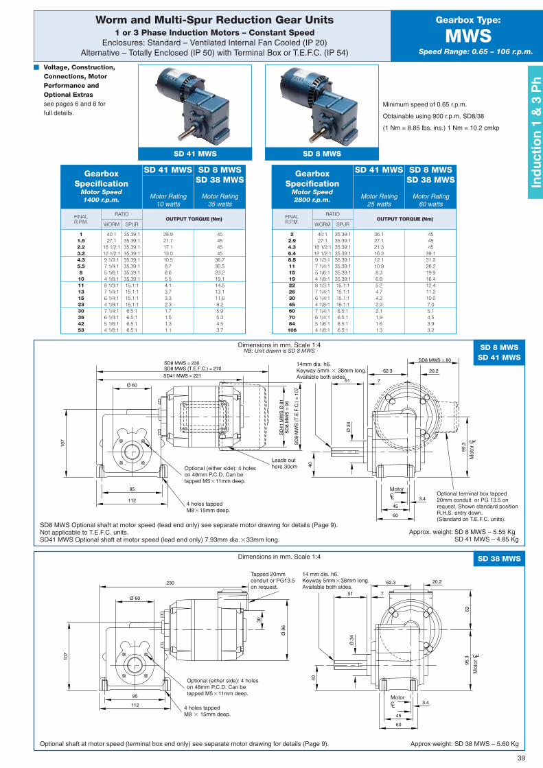
39
Worm and Multi-Spur Reduction Gear Units1 or 3 Phase Induction Motors – Constant Speed
Enclosures: Standard – Ventilated Internal Fan Cooled (IP 20)Alternative – Totally Enclosed (IP 50) with Terminal Box or T.E.F.C. (IP 54)
Gearbox Type:
MWSSpeed Range: 0.65 – 106 r.p.m.
FINALR.P.M. OUTPUT TORQUE (Nm)
WORM
RATIO
SPUR
SD 41 MWS SD 8 MWS
� Voltage, Construction,Connections, MotorPerformance andOptional Extrassee pages 6 and 8 forfull details.
Minimum speed of 0.65 r.p.m.
Obtainable using 900 r.p.m. SD8/38
(1 Nm = 8.85 lbs. ins.) 1 Nm = 10.2 cmkp
GearboxSpecification
Motor Speed1400 r.p.m. Motor Rating
10 wattsMotor Rating
35 watts
SD 41 MWS SD 8 MWSSD 38 MWS
11.52.23.24.35.58101113152330354253
40:127:1
18 1/2:112 1/2:19 1/3:17 1/4:15 1/6:14 1/8:18 1/3:17 1/4:16 1/4:14 1/8:17 1/4:16 1/4:15 1/6:14 1/8:1
35.39:135.39:135.39:135.39:135.39:135.39:135.39:135.39:115.1:115.1:115.1:115.1:16.5:16.5:16.5:16.5:1
28.921.717.113.010.58.76.65.54.13.73.32.31.71.51.31.1
45454545
36.730.523.219.114.513.111.68.25.95.34.53.7
FINALR.P.M. OUTPUT TORQUE (Nm)
WORM
RATIO
SPUR
GearboxSpecification
Motor Speed2800 r.p.m. Motor Rating
25 wattsMotor Rating
60 watts
SD 41 MWS SD 8 MWSSD 38 MWS
22.94.36.48.511151922263045607084106
40:127:1
18 1/2:112 1/2:19 1/3:17 1/4:15 1/6:14 1/8:18 1/3:17 1/4:16 1/4:14 1/8:17 1/4:16 1/4:15 1/6:14 1/8:1
35.39:135.39:135.39:135.39:135.39:135.39:135.39:135.39:115.1:115.1:115.1:115.1:16.5:16.5:16.5:16.5:1
36.127.121.316.312.110.98.36.85.24.74.22.92.11.91.61.3
454545
39.131.226.219.916.412.411.210.07.05.14.53.93.2
63
30
Ø 9
6
230
751
Ø 3
4
40
95.3
20.262.3
Ø 60
95
112 3.4
60
45
107
SD
41 M
WS
Ø 8
1S
D8
MW
S =
96
SD41 MWS = 221751
Ø 3
4
40
95.3
20.262.3
Ø 60
95
112 3.4
60
45
107
SD
8 M
WS
(T
.E.F
.C.)
= 1
07
SD8 MWS = 230SD8 MWS (T.E.F.C.) = 270
SD8 MWS = 80
SD 38 MWS
SD 8 MWSSD 41 MWS
Dimensions in mm. Scale 1:4
Dimensions in mm. Scale 1:4NB: Unit drawn is SD 8 MWS
Optional shaft at motor speed (terminal box end only) see separate motor drawing for details (Page 9).
SD8 MWS Optional shaft at motor speed (lead end only) see separate motor drawing for details (Page 9).Not applicable to T.E.F.C. units.SD41 MWS Optional shaft at motor speed (lead end only) 7.93mm dia.�33mm long.
Approx weight: SD 38 MWS – 5.60 Kg
Approx. weight: SD 8 MWS – 5.55 KgSD 41 MWS – 4.85 Kg
Leads outhere 30cm
4 holes tappedM8�15mm deep.
4 holes tappedM8 � 15mm deep.
14mm dia. h6.Keyway 5mm � 38mm long.Available both sides.
14 mm dia. h6.Keyway 5mm�38mm long.Available both sides.
Optional terminal box tapped20mm conduit or PG 13.5 onrequest. Shown standard positionR.H.S. entry down.(Standard on T.E.F.C. units).
Tapped 20mmconduit or PG13.5on request.
Optional (either side): 4 holeson 48mm P.C.D. Can betapped M5�11mm deep.
Optional (either side): 4 holeson 48mm P.C.D. Can betapped M5�11mm deep.
Ind
uct
ion
1 &
3 P
h
MotorCL
MotorCL
Mot
or C L
Mot
or C L
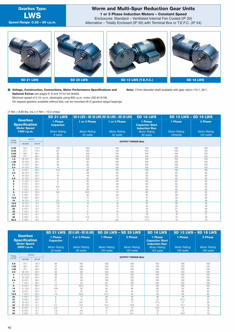
OUTPUT TORQUE (Nm)
OUTPUT TORQUE (Nm)
FINALR.P.M.
FINALR.P.M.
1 or 3 Phase
Motor Rating55 watts
1 PhaseCapacitor StartInduction Run
Motor Rating95 watts
RATIO
RATIO
WORM
WORM
SPUR
SPUR
Worm and Multi-Spur Reduction Gear Units1 or 3 Phase Induction Motors – Constant Speed
Enclosures: Standard – Ventilated Internal Fan Cooled (IP 20)Alternative – Totally Enclosed (IP 50) with Terminal Box or T.E.F.C. (IP 54)
Gearbox Type:
LWSSpeed Range: 0.22 – 90 r.p.m.
SD 21 LWS SD 29 LWS SD 13 LWS (T.E.F.C.)
� Voltage, Construction, Connections, Motor Performance Specifications andOptional Extras see pages 6, 8 and 10 for full details.Minimum speed of 0.15 r.p.m. obtainable using 900 r.p.m. motor (SD 8/13/18).On request gearbox available without feet, can be mounted off of gearbox spigot tappings.
Note: 17mm diameter shaft available with gear ratio’s 115:1, 56:1.
(1 Nm = 8.85 lbs. ins.) (1 Nm = 10.2 cmkp)
GearboxSpecification
Motor Speed1400 r.p.m.
1 PhaseCapacitor
Motor Rating8 watts
SD 21 LWS1 or 3 Phase
Motor Rating35 watts
SD 8 LWS – SD 38 LWS SD 28 LWS – SD 29 LWS SD 18 LWS1 Phase
Motor Rating100watts
3 Phase
Motor Rating125 watts
SD 13 LWS – SD 18 LWS
SD 18 LWS
0.220.450.620.921.51.852.22.43
3.44
4.55678911
13.516
18.522.528323745
56.5
0.91.251.853.045
5.4781012
15.522273745567490
54:127:140:127:1
16 1/2:113 1/2:111 1/3:110 1/3:18 1/3:116 1/2:114 1/2:112 1/2:111 1/3:19 1/3:18 1/3:17 1/4:16 1/4:15 1/6:14 1/8:114 1/2:112 1/2:110 1/3:18 1/3:17 1/4:16 1/4:15 1/6:14 1/8:1
27:140:127:1
16 1/2:112 1/12:110 1/3:19 1/3:17 1/4:16 1/4:111 1/3:19 1/3:17 1/4:15 1/6:14 1/8:112 1/2:110 1/3:18 1/3:16 1/4:15 1/6:1
115:1115:156:156:156:156:156:156:156:125:125:125:125:125:125:125:125:125:125:16:16:16:16:16:16:16:16:1
115:156:156:156:156:156:156:156:156:125:125:125:125:125:16:16:16:16:16:1
10067453525222018
15.51110987
6.56
5.654
2.52.31.91.71.51.41.21.0
845743322620211715
10.69
7.5653
2.12.01.61.4
1001001009379605950
45.53227
22.517158.46.36
4.84.2
10010010010010010010084765345
37.5292514
10.51087
10010010010010010010010091625445353017
12.6129.68.4
100100100100100100100100956257463631
17.513
12.5108
10010010010010010010010010062625644
37.521
15.71512
10.5
10010010010010010010010010062626256472619181513
1001001001001009383786649444035302826
24.5201711108765
4.84
10010010010010010010010010062626255494541373227171613111098
6.6
10010010010010010010010010062626262626262625547302723201816
13.511.3
100100100100100100100100100626262626262626258503228232118161412
100100100100100100100100100626262626262626262623935282623211815
GearboxSpecification
Motor Speed2800 r.p.m.
1 PhaseCapacitor
Motor Rating20 watts
1 or 3 Phase
Motor Rating60 watts
1 Phase
Motor Rating100 watts
3 Phase
Motor Rating120 watts
1 PhaseCapacitor StartInduction Run
Motor Rating125 watts
1 Phase
Motor Rating150 watts
3 Phase
Motor Rating190 watts
SD 21 LWS SD 8 LWS – SD 38 LWS SD 28 LWS – SD 29 LWS SD 18 LWS SD 13 LWS – SD 18 LWS
40
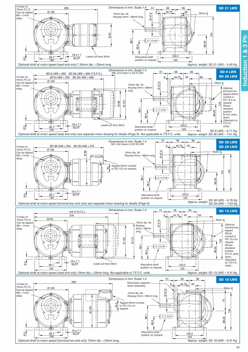
565651
226 44.75
Ø 4
7.6
123
103.2
68.2
5
134
88.1
48.4
Ø 8
1
Ø 125
228
19 x 7.1SLOT85.7
1209.5
SD 21 LWSDimensions in mm. Scale 1:4
Optional shaft at motor speed (lead end only) 7.93mm dia.�33mm long. Approx. weight: SD 21 LWS – 5.45 Kg
Leads out here 30cm Alternative shaftposition on request.
Motor CL
4 holes on70mm P.C.D.Can be tappedM5�11mmdeep.
15mm dia. h6.Keyway 5mm�38mm long.
30
Ø 9
6
SD 38 LWS = 254 SD 29 LWS = 273
565651
226 44.75
Ø 4
7.6Ø 125
131
123103.2
19 x 7.1SLOT85.7
1209.5
68.2
5
134
88.1
48.4
SD 38 LWSSD 29 LWS
Dimensions in mm. Scale 1:4NB: Unit drawn is SD 38 LWS
Optional shaft at motor speed (terminal box end only) see separate motor drawing for details (Page 9). Approx. weight: SD 38 LWS – 6.76 KgSD 29 LWS – 7.53 Kg
Tapped 20mm conduitor PG 13.5 on request.
Alternative shaftposition on request.
4 holes on70mm P.C.D.Can be tappedM5�11mmdeep.
15mm dia. h6Keyway 5mm�38mm long.
SD 8 LWS = 290 SD 28 LWS = 309 (T.E.F.C.)
Ø 9
6
SD 8 LWS = 250 SD 28 LWS = 269
565651
226 44.75
Ø 4
7.6Ø 125
123103.219 x 7.1
SLOT85.71209.
5
68.2
5
134
88.1
48.4
Ø 1
07
80
Dimensions in mm. Scale 1:4NB: Unit drawn is SD 8 LWS
Optional shaft at motor speed (lead end only) see separate motor drawing for details (Page 9). Not applicable to T.E.F.C. units.
Alternative shaftposition on request.
Alternative shaftposition on request
4 holes on70mm P.C.D.Can be tappedM5�11mmdeep.
15mm dia. h6.Keyway 5mm�38mmlong.
75
39.5
Ø 1
20
283565651
226 44.75
Ø 4
7.6Ø 125
123103.2
19 x 7.1SLOT85.7
1209.5
68.2
5
134
88.1
48.4
SD 18 LWSDimensions in mm. Scale 1:4
Optional shaft at motor speed (terminal box end only) 10mm dia.�33mm long. Approx. weight: SD 18 LWS – 9.31 Kg
Alternative shaftposition on request.
4 holes on70mm P.C.D.Can be tappedM5�11mmdeep.
15mm dia. h6.Keyway 5mm�38mm long.
Tapped 20mm conduitor PG 13.5 onrequest.
Ø 1
20
278
565651
226 44.75
Ø 4
7.6Ø125
123
103.2
19 x 7.1SLOT85.7
120
9.5
68.2
5
134
88.1
48.4
Ø 1
31
316 (T.E.F.C.)94
SD 13 LWSDimensions in mm. Scale 1:4
Optional shaft at motor speed (lead end only) 10mm dia.�33mm long. Not applicable to T.E.F.C. units. Approx. weight: SD 13 LWS – 9.31 Kg
Leads out here 30cm Alternative shaftposition on request.
4 holes on70mm P.C.D.Can be tappedM5�11mmdeep.
15mm dia. h6.Keyway5mm�38mmlong.
Optionalterminal boxtapped 20mmconduit orPG 13.5 onrequest.ShownstandardpositionR.H.S. entrydown.(Standard onT.E.F.C.units).
Optionalterminal boxtapped20mmconduit orPG 13.5 onrequest.ShownstandardpositionR.H.S. entrydown.(Standardon T.E.F.C.units).
SD 8 LWSSD 28 LWS
SD 8 LWS – 6.71 KgApprox. weight: SD 28 LWS – 7.51 Kg
Leads out here 30cm
Electrolytic capacitorwhen necessary.
41
Motor CL
Motor CL
Motor CL
Motor CL
Ind
uct
ion
1 &
3 P
h
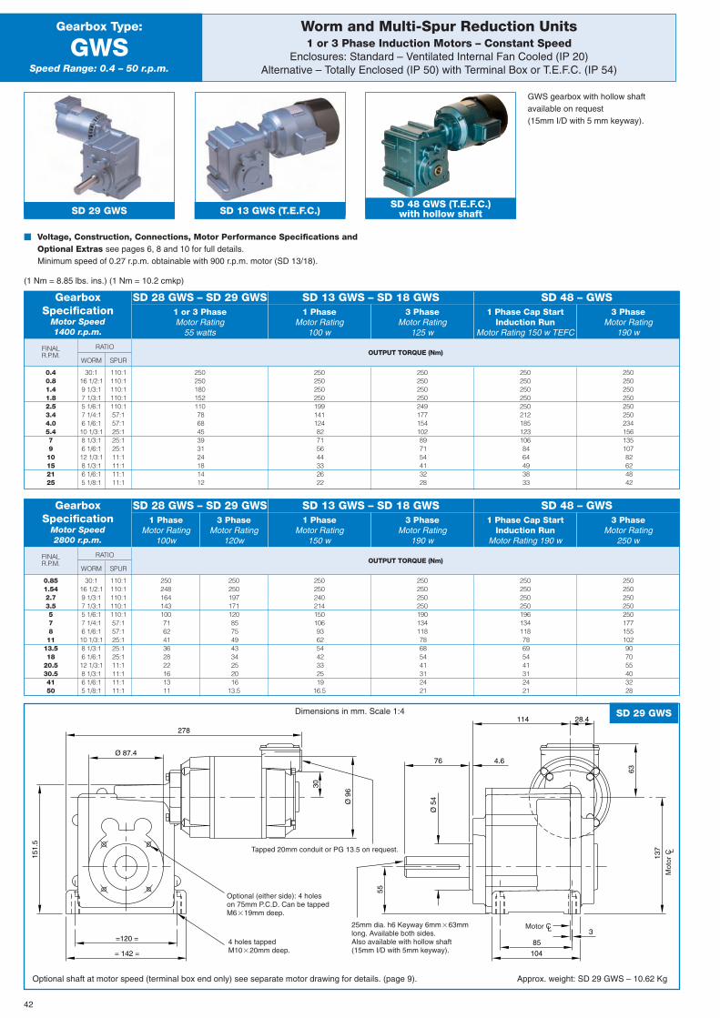
FINALR.P.M. OUTPUT TORQUE (Nm)
RATIO
WORM SPUR
Worm and Multi-Spur Reduction Units1 or 3 Phase Induction Motors – Constant Speed
Enclosures: Standard – Ventilated Internal Fan Cooled (IP 20)Alternative – Totally Enclosed (IP 50) with Terminal Box or T.E.F.C. (IP 54)
Gearbox Type:
GWSSpeed Range: 0.4 – 50 r.p.m.
SD 29 GWS SD 13 GWS (T.E.F.C.)SD 48 GWS (T.E.F.C.)
with hollow shaft
GearboxSpecification
Motor Speed1400 r.p.m.
1 or 3 PhaseMotor Rating
55 watts
1 PhaseMotor Rating
100 w
1 Phase Cap StartInduction Run
Motor Rating 150 w TEFC
3 PhaseMotor Rating
125 w
3 PhaseMotor Rating
190 w
SD 28 GWS – SD 29 GWS SD 13 GWS – SD 18 GWS SD 48 – GWS
42
0.40.81.41.82.53.44.05.47910152125
30:116 1/2:19 1/3:17 1/3:15 1/6:17 1/4:16 1/6:110 1/3:18 1/3:16 1/6:112 1/3:18 1/3:16 1/6:15 1/8:1
110:1110:1110:1110:1110:157:157:125:125:125:111:111:111:111:1
250250180152110786845393124181412
25025025025019914112482715644332622
250250250250249177154102897154413228
2502502502502502121851231068464493833
25025025025025025023415613510782624842
FINALR.P.M. OUTPUT TORQUE (Nm)
RATIO
WORM SPUR
GearboxSpecification
Motor Speed2800 r.p.m.
1 PhaseMotor Rating
100w
3 PhaseMotor Rating
120w
1 PhaseMotor Rating
150 w
1 Phase Cap StartInduction Run
Motor Rating 190 w
3 PhaseMotor Rating
190 w
3 PhaseMotor Rating
250 w
SD 28 GWS – SD 29 GWS SD 13 GWS – SD 18 GWS SD 48 – GWS
0.851.542.73.557811
13.518
20.530.54150
30:116 1/2:19 1/3:17 1/3:15 1/6:17 1/4:16 1/6:110 1/3:18 1/3:16 1/6:112 1/3:18 1/3:16 1/6:15 1/8:1
110:1110:1110:1110:1110:157:157:125:125:125:111:111:111:111:1
250248164143100716241362822161311
2502501971711208575494334252016
13.5
25025024021415010693625442332519
16.5
25025025025019613411878695441312421
25025025025019013411878685441312421
250250250250250177155102907055403228
Ø 9
6
63
30
151.
5
55
137
Ø 5
4
3
278
Ø 87.4
28.4114
4.676
104
85
= 142 =
=120 =
SD 29 GWSDimensions in mm. Scale 1:4
Optional shaft at motor speed (terminal box end only) see separate motor drawing for details. (page 9). Approx. weight: SD 29 GWS – 10.62 Kg
Tapped 20mm conduit or PG 13.5 on request.
Optional (either side): 4 holeson 75mm P.C.D. Can be tappedM6�19mm deep.
4 holes tappedM10�20mm deep.
25mm dia. h6 Keyway 6mm�63mmlong. Available both sides.Also available with hollow shaft(15mm I/D with 5mm keyway).
� Voltage, Construction, Connections, Motor Performance Specifications andOptional Extras see pages 6, 8 and 10 for full details.Minimum speed of 0.27 r.p.m. obtainable with 900 r.p.m. motor (SD 13/18).
GWS gearbox with hollow shaftavailable on request(15mm I/D with 5 mm keyway).
Motor CL
Mot
or C L
(1 Nm = 8.85 lbs. ins.) (1 Nm = 10.2 cmkp)
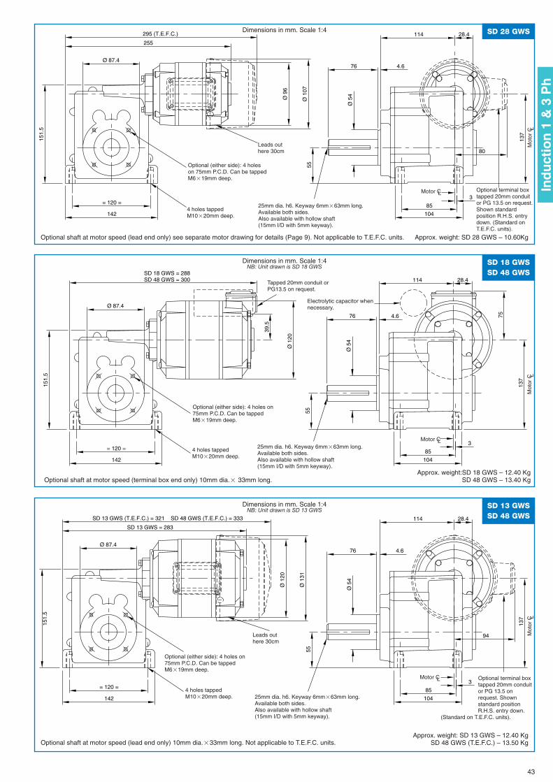
Ø 9
6
151.
5
55
137
Ø 5
4
3
255
Ø 87.4
28.4114
4.676
104
85
142
= 120 =
Ø 1
07
295 (T.E.F.C.)
80
SD 28 GWSDimensions in mm. Scale 1:4
Optional shaft at motor speed (lead end only) see separate motor drawing for details (Page 9). Not applicable to T.E.F.C. units. Approx. weight: SD 28 GWS – 10.60Kg
Leads outhere 30cm
4 holes tappedM10�20mm deep.
25mm dia. h6. Keyway 6mm�63mm long.Available both sides.Also available with hollow shaft(15mm I/D with 5mm keyway).
Optional (either side): 4 holeson 75mm P.C.D. Can be tappedM6�19mm deep.
43
SD 18 GWS = 288SD 48 GWS = 300
75
39.5
Ø 1
20
151.
5
55
137
Ø 5
4
3
Ø 87.4
28.4114
4.676
104
85
142
= 120 =
SD 18 GWSSD 48 GWS
Dimensions in mm. Scale 1:4NB: Unit drawn is SD 18 GWS
Optional shaft at motor speed (terminal box end only) 10mm dia.� 33mm long.Approx. weight:SD 18 GWS – 12.40 Kg
SD 48 GWS – 13.40 Kg
4 holes tappedM10�20mm deep.
Optional (either side): 4 holes on75mm P.C.D. Can be tappedM6�19mm deep.
Tapped 20mm conduit orPG13.5 on request.
Electrolytic capacitor whennecessary.
25mm dia. h6. Keyway 6mm�63mm long.Available both sides.Also available with hollow shaft(15mm I/D with 5mm keyway).
Ø 1
20
151.
5
55
137
Ø 5
4
3
SD 13 GWS = 283
Ø 87.4
28.4114
4.676
104
85
142
= 120 =
Ø 1
31
SD 13 GWS (T.E.F.C.) = 321 SD 48 GWS (T.E.F.C.) = 333
94
SD 13 GWSSD 48 GWS
Dimensions in mm. Scale 1:4NB: Unit drawn is SD 13 GWS
Optional shaft at motor speed (lead end only) 10mm dia.�33mm long. Not applicable to T.E.F.C. units.Approx. weight: SD 13 GWS – 12.40 Kg
SD 48 GWS (T.E.F.C.) – 13.50 Kg
Optional (either side): 4 holes on75mm P.C.D. Can be tappedM6�19mm deep.
4 holes tappedM10�20mm deep. 25mm dia. h6. Keyway 6mm�63mm long.
Available both sides.Also available with hollow shaft(15mm I/D with 5mm keyway).
Optional terminal boxtapped 20mm conduitor PG 13.5 onrequest. Shownstandard positionR.H.S. entry down.
(Standard on T.E.F.C. units).
Optional terminal boxtapped 20mm conduitor PG 13.5 on request.Shown standardposition R.H.S. entrydown. (Standard onT.E.F.C. units).
Leads outhere 30cm
Ind
uct
ion
1 &
3 P
h
Motor CL
Mot
or C L
Mot
or C L
Motor CL
Motor CL
Mot
or C L
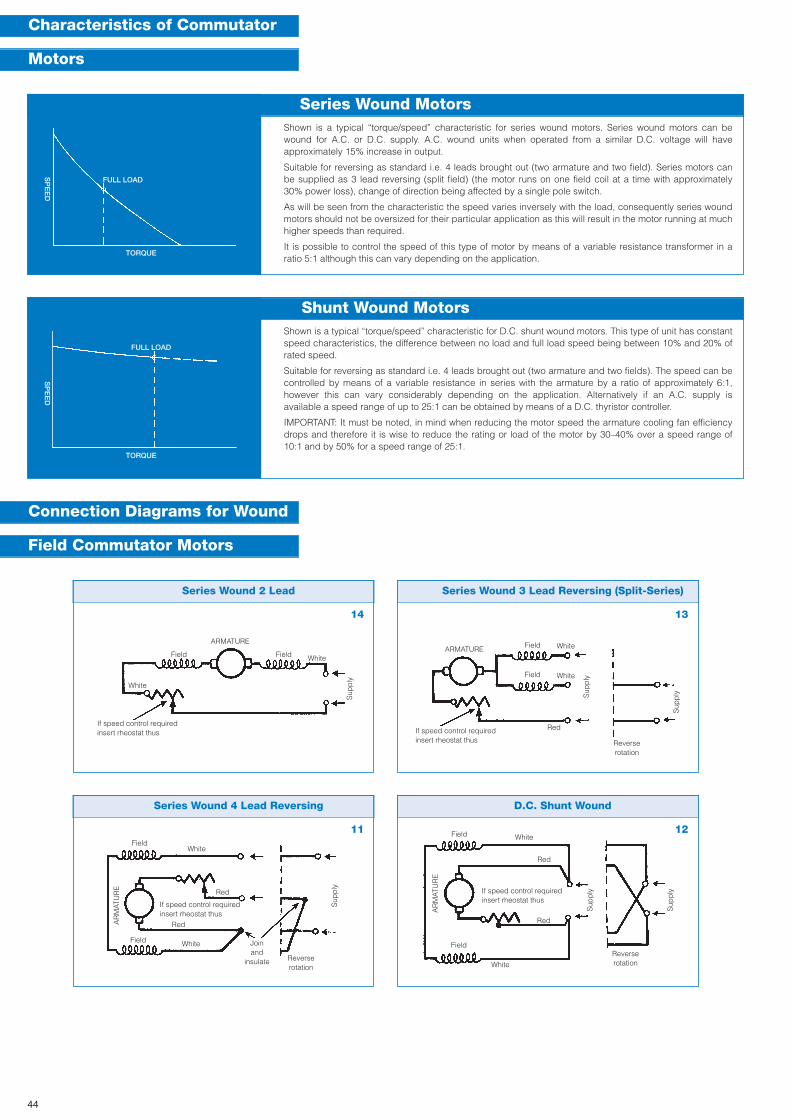
Series Wound 2 Lead
Series Wound 4 Lead Reversing
Series Wound 3 Lead Reversing (Split-Series)
D.C. Shunt Wound
Shown is a typical “torque/speed” characteristic for series wound motors. Series wound motors can bewound for A.C. or D.C. supply. A.C. wound units when operated from a similar D.C. voltage will haveapproximately 15% increase in output.
Suitable for reversing as standard i.e. 4 leads brought out (two armature and two field). Series motors canbe supplied as 3 lead reversing (split field) (the motor runs on one field coil at a time with approximately30% power loss), change of direction being affected by a single pole switch.
As will be seen from the characteristic the speed varies inversely with the load, consequently series woundmotors should not be oversized for their particular application as this will result in the motor running at muchhigher speeds than required.
It is possible to control the speed of this type of motor by means of a variable resistance transformer in aratio 5:1 although this can vary depending on the application.
ARMATURE
AR
MAT
UR
E
FieldField
Field
Field
White
White
White
Red
Red
White
If speed control requiredinsert rheostat thus
Joinand
insulate Reverserotation
If speed control requiredinsert rheostat thus
Sup
ply
Sup
ply
ARMATURE
AR
MAT
UR
E
Field
Field
Field
Field
White
White
Red
Red
Red
White
White
Reverserotation
Reverserotation
If speed control requiredinsert rheostat thus
Sup
ply
Sup
ply
Sup
ply
Sup
ply
Characteristics of Commutator
Motors
Connection Diagrams for Wound
Field Commutator Motors
Series Wound Motors
FULL LOAD
SP
EE
D
TORQUE
Shown is a typical “torque/speed” characteristic for D.C. shunt wound motors. This type of unit has constantspeed characteristics, the difference between no load and full load speed being between 10% and 20% ofrated speed.
Suitable for reversing as standard i.e. 4 leads brought out (two armature and two fields). The speed can becontrolled by means of a variable resistance in series with the armature by a ratio of approximately 6:1,however this can vary considerably depending on the application. Alternatively if an A.C. supply isavailable a speed range of up to 25:1 can be obtained by means of a D.C. thyristor controller.
IMPORTANT: It must be noted, in mind when reducing the motor speed the armature cooling fan efficiencydrops and therefore it is wise to reduce the rating or load of the motor by 30–40% over a speed range of10:1 and by 50% for a speed range of 25:1.
Shunt Wound Motors
SP
EE
D
FULL LOAD
TORQUE
14
11
13
12
If speed control requiredinsert rheostat thus
44
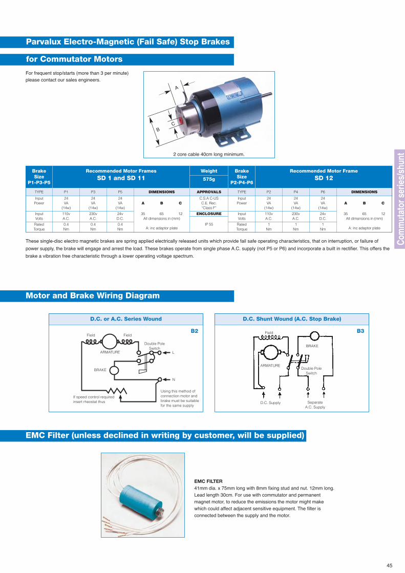
DIMENSIONSTYPE
D.C. or A.C. Series Wound D.C. Shunt Wound (A.C. Stop Brake)
ARMATURE
Field
BRAKE
N
L
Double PoleSwitch
Double PoleSwitch
SeparateA.C. Supply
D.C. Supply
Parvalux Electro-Magnetic (Fail Safe) Stop Brakes
for Commutator Motors
For frequent stop/starts (more than 3 per minute)please contact our sales engineers.
P1 P3 P5 DIMENSIONS APPROVALS TYPE P2 P4 P6
BrakeSize
P1-P3-P5
Weight
575g
BrakeSize
P2-P4-P6
Recommended Motor Frames
SD 1 and SD 11Recommended Motor Frame
SD 12
InputPower
InputVolts
RatedTorque
110vA.C.
0.4Nm
230vA.C.
0.4Nm
24vD.C.
0.4Nm
ENCLOSURE
IP 55
InputVolts
RatedTorque
110vA.C.
1Nm
230vA.C.
1Nm
24vD.C.
1Nm
24VA
(14w)
24VA
(14w)
24VA
(14w)A B C
35 65 12All dimensions in (mm)
A: inc adaptor plate
C.S.A C-USC.E. Rec.“Class F”
InputPower
24VA
(14w)
24VA
(14w)
24VA
(14w)A B C
35 65 12All dimensions in (mm)
A: inc adaptor plate
Motor and Brake Wiring Diagram
EMC Filter (unless declined in writing by customer, will be supplied)
B2 B3FieldField
BRAKE
ARMATURE
If speed control requiredinsert rheostat thus
Using this method ofconnection motor andbrake must be suitablefor the same supply
These single-disc electro magnetic brakes are spring applied electrically released units which provide fail safe operating characteristics, that on interruption, or failure of
power supply, the brake will engage and arrest the load. These brakes operate from single phase A.C. supply (not P5 or P6) and incorporate a built in rectifier. This offers the
brake a vibration free characteristic through a lower operating voltage spectrum.
A
BC
2 core cable 40cm long minimum.
45
Com
mut
ator
ser
ies/
shun
t
EMC FILTER41mm dia. x 75mm long with 8mm fixing stud and nut. 12mm long.Lead length 30cm. For use with commutator and permanentmagnet motor, to reduce the emissions the motor might makewhich could affect adjacent sensitive equipment. The filter isconnected between the supply and the motor.
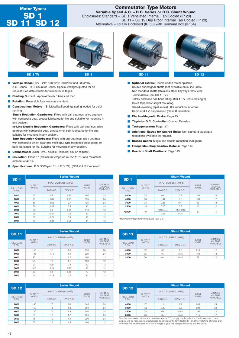
MINIMUMVOLTAGE
AVAILABLEFULL LOADR.P.M.
OUTPUTWATTS
INPUTWATTS
INPUT CURRENT (AMPS)
240V A.C. 220V A.C.
Commutator Type MotorsVariable Speed A.C. – D.C. Series or D.C. Shunt Wound
Enclosures: Standard – SD 1 Ventilated Internal Fan Cooled (IP 20)SD 11 – SD 12 Drip Proof Internal Fan Cooled (IP 23)
Alternative – Totally Enclosed (IP 50) with Terminal Box (IP 54)
Motor Types:
SD 1SD 11 SD 12
SD 1 TV SD 1 SD 11
� Voltage Range: 12v – 24v, 100/120v, 200/220v and 230/250v,A.C. Series – D.C. Shunt or Series. Special voltages quoted for onrequest. See data column for minimum voltages.
� Starting Current: Approximately 3 times full load.
� Rotation: Reversible four leads as standard.
� Construction: Motors – Shielded ball bearings spring loaded for quietrunning.Single Reduction Gearboxes: Fitted with ball bearings, alloy gearboxwith composite gear, grease lubricated for life and suitable for mounting inany position.In-Line Double Reduction Gearboxes: Fitted with ball bearings, alloygearbox with composite gear, grease or oil bath lubricated for life andsuitable for mounting in any position.Spur Reduction Gearboxes: Fitted with ball bearings, alloy gearboxwith composite pinion gear and multi-spur type hardened steel gears, oilbath lubricated for life. Suitable for mounting in any position.
� Connections: 30cm P.V.C. flexible (Terminal box on request).
� Insulation: Class ‘F’ (maximum temperature rise 115°C at a maximumambient of 40°C).
� Specifications: B.S. 5000 part 11. (I.E.C. 72). (CSA C-US if required).
� Optional Extras: Double ended motor spindles.Double ended gear shafts (not available on in-line units).Non standard shafts (stainless steel, keyways, flats, etc).Terminal box. (not SD 1 T.V.).Totally enclosed half hour rating. (SD 1 T.V. reduced length).Holes tapped for spigot mounting.3 lead reversing (split series) 30% reduction in torque.Radio and T.V. suppression (class B insulation).
� Electro-Magnetic Brake: Page 45.
� Thyristor D.C. Controller: Contact Parvalux.
� Tachogenerator: Page 117.
� Additional Extras for Geared Units: Non standard cataloguereductions available on request.
� Bronze Gears: Single and double reduction final gears.
� Flange Mounting Gearbox Details: Page 114.
� Gearbox Shaft Positions: Page 113.
*Maximum voltage for this output is 120v D.C.
SD 1Series Wound
SD 12
6500
5500
4000
4000
3000
3000
2500
2000
75
63
50
38
38
25
15
10
0.8
0.68
0.65
0.45
0.6
0.27
0.25
0.23
0.95
0.75
0.7
0.5
0.65
0.3
0.3
0.25
160
130
125
90
110
40
40
37
24
24
24
24
12
12
12
12
MINIMUMVOLTAGE
AVAILABLEFULL LOADR.P.M.
OUTPUTWATTS
INPUTWATTS
INPUT CURRENT (AMPS)
240V D.C. 220V D.C..
SD 1Shunt Wound
5000
4000
3000
2500
*2000
75
50
38
15
10
0.6
0.44
0.36
0.25
120V D.C.
0.23
0.7
0.5
0.41
0.3
110V D.C.
0.25
140
100
80
40
37
24
12
12
12
12
MINIMUMVOLTAGE
AVAILABLEFULL LOADR.P.M.
OUTPUTWATTS
INPUTWATTS
INPUT CURRENT (AMPS)
240V D.C. 220V D.C..
SD 11Shunt Wound
4000
3000
2000
125
95
50
0.9
0.7
0.4
1.0
0.75
0.45
216
168
96
12
12
12
MINIMUMVOLTAGE
AVAILABLEFULL LOADR.P.M.
OUTPUTWATTS
INPUTWATTS
INPUT CURRENT (AMPS)
240V D.C. 220V D.C..
SD 12Shunt Wound
4000
3000
2500
2000
150
125
75
60
1.0
0.82
0.6
0.4
1.1
0.9
0.65
0.46
265
200
140
115
24
24
12
12
MINIMUMVOLTAGE
AVAILABLEFULL LOADR.P.M.
OUTPUTWATTS
INPUTWATTS
INPUT CURRENT (AMPS)
240V A.C. 220V A.C.
SD 11Series Wound
6000
5000
4000
3000
3000
3000
2000
2000
150
125
95
75
30
18.5
30
15
1.3
1.15
1.1
1.0
0.27
0.24
0.6
0.19
1.6
1.4
1.2
1.1
0.3
0.25
0.65
0.2
290
220
190
160
60
50
70
40
36
24
12
12
12
12
12
12
MINIMUMVOLTAGE
AVAILABLEFULL LOADR.P.M.
OUTPUTWATTS
INPUTWATTS
INPUT CURRENT (AMPS)
240V A.C. 220V A.C.
SD 12Series Wound
6000
4000
4000
3000
2500
2000
190
150
125
95
75
50
1.5
1.8
1.2
1.1
1.3
1.2
1.6
1.8
1.3
1.2
1.4
1.3
340
350
240
200
200
160
24
24
24
24
24
12
Shunt wound motor outputs are based on a pure D.C. supply (i.e. form factor 1) with electronic control,outputs will be reduced, to what degree depends on the form factor (FF) and the matching of motor andcontroller. We recommend a controller range to give the best performance and brush life.
46
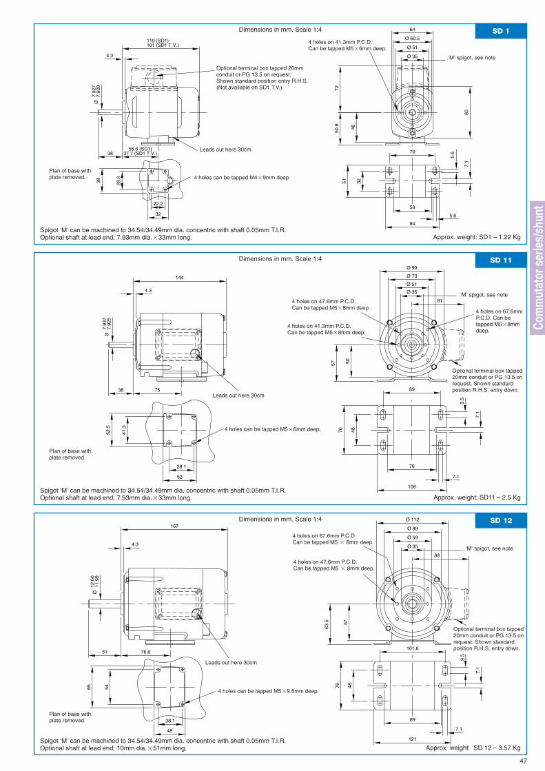
64
119 (SD1)Ø 51
Ø 60.5
Ø 35
80
101 (SD1 T.V.)
4.3
7.92
0Ø
7.92
7
38
7250
.8
55.6 (SD1)
28.6
22.2
5.6
7.1
70
5.6
59
84
46
51
37.7 (SD1 T.V.)
38
32
32
SD 1Dimensions in mm. Scale 1:4
Spigot ‘M’ can be machined to 34.54/34.49mm dia. concentric with shaft 0.05mm T.I.R.Optional shaft at lead end, 7.93mm dia.�33mm long. Approx. weight: SD1 – 1.22 Kg
Leads out here 30cm
4 holes on 41.3mm P.C.D.Can be tapped M5�6mm deep.
.‘M’ spigot, see note
Plan of base withplate removed.
47
Optional terminal box tapped 20mmconduit or PG 13.5 on request.Shown standard position entry R.H.S.(Not available on SD1 T.V.).
Ø 99
Ø 51
Ø 73
Ø 354.3
7.93
7Ø
7.92
5
38
144
7.1
9.5
7.1
89
76
48
108
57
76
75
52
38.1
52.5
41.3
50
81
SD 11Dimensions in mm. Scale 1:4
Spigot ‘M’ can be machined to 34.54/34.49mm dia. concentric with shaft 0.05mm T.I.R.Optional shaft at lead end, 7.93mm dia.�33mm long. Approx. weight: SD11 – 2.5 Kg
51
Ø 59
Ø 89
Ø 35
Ø 112
4.3
167
11.9
912
.00
Ø
76.6101.6
9.5
57
7.1
7.1
48
89
121
63.5
76
38.1
48
5465
88
SD 12Dimensions in mm. Scale 1:4
Spigot ‘M’ can be machined to 34.54/34.49mm dia. concentric with shaft 0.05mm T.I.R.Optional shaft at lead end, 10mm dia.�51mm long. Approx. weight: SD 12 – 3.57 Kg
4 holes can be tapped M4�9mm deep.
Plan of base withplate removed.
Leads out here 30cm
4 holes can be tapped M5�6mm deep.
Optional terminal box tapped20mm conduit or PG 13.5 onrequest. Shown standardposition R.H.S. entry down.
4 holes on 41.3mm P.C.D.Can be tapped M5�8mm deep.
4 holes on 47.6mm P.C.D.Can be tapped M5�8mm deep.
4 holes on 67.6mmP.C.D. Can betapped M5�8mmdeep.
Plan of base withplate removed.
Leads out here 30cm
4 holes can be tapped M5�9.5mm deep.
Optional terminal box tapped20mm conduit or PG 13.5 onrequest. Shown standardposition R.H.S. entry down.
4 holes on 47.6mm P.C.D.Can be tapped M5 � 8mm deep.
4 holes on 67.6mm P.C.D.Can be tapped M5 � 8mm deep.
Com
mut
ator
ser
ies/
shun
t‘M’ spigot, see note.
.‘M’ spigot, see note
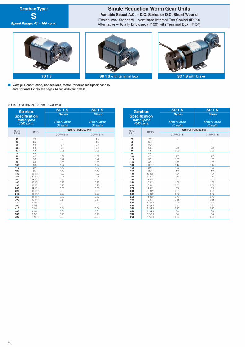
COMPOSITE
OUTPUT TORQUE (Nm)FINALR.P.M. COMPOSITE
RATIO
Single Reduction Worm Gear UnitsVariable Speed A.C. – D.C. Series or D.C. Shunt Wound
Enclosures: Standard – Ventilated Internal Fan Cooled (IP 20)Alternative – Totally Enclosed (IP 50) with Terminal Box (IP 54)
Gearbox Type:
SSpeed Range: 43 – 960 r.p.m.
SD 1 S SD 1 S with terminal box SD 1 S with brake
� Voltage, Construction, Connections, Motor Performance Specificationsand Optional Extras see pages 44 and 46 for full details.
(1 Nm = 8.85 lbs. ins.) (1 Nm = 10.2 cmkp)
GearboxSpecification
Motor Speed3000 r.p.m.
Series
Motor Rating38 watts
Shunt
Motor Rating38 watts
SD 1 S SD 1 S
434550556268758390100110120130145160180190205220240265290320360410480580725
70:166:160:154:148:144:140:136:133:130:127:125:1
22 1/2:120 1/2:118 1/2:116 1/2:115 1/2:114 1/2:113 1/2:112 1/2:111 1/3:110 1/3:19 1/3:18 1/3:17 1/4:16 1/4:15 1/6:14 1/8:1
––
2.32.32.031.811.581.471.361.241.191.131.020.90.790.730.730.680.620.570.570.510.450.40.340.310.280.23
1.51.52.32.32.031.811.581.471.361.241.191.131.020.90.790.730.730.680.620.570.570.510.450.40.340.310.280.23
COMPOSITE
OUTPUT TORQUE (Nm)FINALR.P.M. COMPOSITE
RATIO
GearboxSpecification
Motor Speed4000 r.p.m.
Series
Motor Rating50 watts
Shunt
Motor Rating50 watts
SD 1 S SD 1 S
556065758590100110120130150160180200220240260275300320350400430480550640780960
70:166:160:154:148:144:140:136:133:130:127:125:1
22 1/2:120 1/2:118 1/2:116 1/2:115 1/2:114 1/2:113 1/2:112 1/2:111 1/3:110 1/3:19 1/3:18 1/3:17 1/4:16 1/4:15 1/6:14 1/8:1
–––
2.32.031.811.71.581.531.471.361.31.241.131.071.020.960.90.850.790.730.680.570.510.450.40.40.28
–––
2.32.031.811.71.581.531.471.361.31.241.131.071.020.960.90.850.790.730.680.570.510.450.40.40.28
48
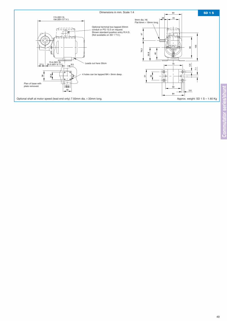
64
174 (SD1 S)
80
156 (SD1 S T.V.)4429
27.5
47
9.5
50.8
73.4 (SD1 S)
28.6
22.2
5.6
7.1
70
5.6
59
84
46
51
55.5 (SD1 S T.V.)
38
32
32
105
76.2
SD 1 SDimensions in mm. Scale 1:4
Optional shaft at motor speed (lead end only) 7.93mm dia.�33mm long. Approx. weight: SD 1 S – 1.60 Kg
Leads out here 30cm
49
4 holes can be tapped M4�9mm deep.
9mm dia. h6.Flat 6mm�19mm long.
Optional terminal box tapped 20mmconduit or PG 13.5 on request.Shown standard position entry R.H.S.(Not available on SD 1 T.V.).
Com
mut
ator
ser
ies/
shun
tPlan of base withplate removed.
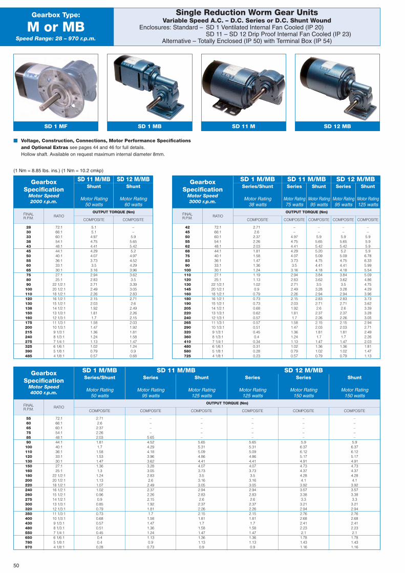
OUTPUT TORQUE (Nm)FINALR.P.M.
COMPOSITE
OUTPUT TORQUE (Nm)FINALR.P.M.COMPOSITE
OUTPUT TORQUE (Nm)FINALR.P.M. COMPOSITE
RATIO
Single Reduction Worm Gear UnitsVariable Speed A.C. – D.C. Series or D.C. Shunt Wound
Enclosures: Standard – SD 1 Ventilated Internal Fan Cooled (IP 20)SD 11 – SD 12 Drip Proof Internal Fan Cooled (IP 23)
Alternative – Totally Enclosed (IP 50) with Terminal Box (IP 54)
Gearbox Type:
M or MBSpeed Range: 28 – 970 r.p.m.
SD 1 MF SD 11 M
� Voltage, Construction, Connections, Motor Performance Specificationsand Optional Extras see pages 44 and 46 for full details.Hollow shaft. Available on request maximum internal diameter 8mm.
(1 Nm = 8.85 lbs. ins.) (1 Nm = 10.2 cmkp)
GearboxSpecification
Motor Speed2000 r.p.m.
Shunt
Motor Rating50 watts
SD 11 M/MBShunt
Motor Rating60 watts
SD 12 M/MB
28303338434550556065758090100110120130138150160175200215240275325390485
72:166:160:154:148:144:140:136:133:130:127:125:1
22 1/2:120 1/2:118 1/2:116 1/2:115 1/2:114 1/2:113 1/3:112 1/3:111 1/3:110 1/3:19 1/3:18 1/3:17 1/4:16 1/6:15 1/8:14 1/8:1
5.15.14.974.754.414.294.073.733.53.162.942.832.712.492.262.152.031.921.811.71.581.471.361.241.131.020.790.57
––
5.95.655.425.24.974.524.293.963.623.53.393.052.832.712.62.492.262.152.031.921.811.581.471.240.90.68
COMPOSITE COMPOSITE COMPOSITE COMPOSITE COMPOSITE COMPOSITERATIO
GearboxSpecification
Motor Speed4000 r.p.m.
Series/Shunt
Motor Rating50 watts
Series
Motor Rating95 watts
Shunt
Motor Rating125 watts
Series
Motor Rating125 watts
Series
Motor Rating150 watts
Shunt
Motor Rating150 watts
SD 1 M/MB SD 11 M/MB SD 12 M/MB
556065758590100110120130150160180200220240260275300320350400430480550650780970
72:166:160:154:148:144:140:136:133:130:127:125:1
22 1/2:120 1/2:118 1/2:116 1/2:115 1/2:114 1/2:113 1/3:112 1/3:111 1/3:110 1/3:19 1/3:18 1/3:17 1/4:16 1/6:15 1/8:14 1/8:1
2.712.62.372.262.031.811.71.581.531.471.361.31.241.131.071.020.960.90.850.790.730.680.570.510.450.40.40.28
––––
5.654.524.294.183.963.623.283.052.832.62.492.372.262.151.921.811.71.581.471.361.241.130.90.73
–––––
5.655.315.094.864.414.073.733.53.163.052.942.832.62.372.262.151.811.71.581.471.361.130.9
–––––
5.655.315.094.864.414.073.733.53.163.052.942.832.62.372.262.151.811.71.581.471.361.130.9
–––––
5.96.376.125.174.914.734.374.284.13.923.573.383.33.212.942.762.682.412.232.11.781.431.16
–––––
5.96.376.125.174.914.734.374.284.13.923.573.383.33.212.942.762.682.412.232.11.781.431.16
COMPOSITE COMPOSITE COMPOSITECOMPOSITERATIO
GearboxSpecification
Motor Speed3000 r.p.m.
Series/Shunt
Motor Rating38 watts
Series
Motor Rating75 watts
Shunt
Motor Rating95 watts
Series
Motor Rating95 watts
Shunt
Motor Rating125 watts
SD 1 M/MB SD 11 M/MB SD 12 M/MB
424550556268758390100110120130145160180190205220240265290320360410480580725
72:166:160:154:148:144:140:136:133:130:127:125:1
22 1/2:120 1/2:118 1/2:116 1/2:115 1/2:114 1/2:113 1/3:112 1/3:111 1/3:110 1/3:19 1/3:18 1/3:17 1/4:16 1/6:15 1/8:14 1/8:1
2.712.62.372.262.031.811.581.471.361.241.191.131.020.90.790.730.730.680.620.570.570.510.450.40.340.310.280.23
––
4.974.754.414.294.073.733.53.162.942.832.712.492.262.152.031.921.811.71.581.471.361.241.131.020.790.57
––
5.95.655.425.205.094.754.414.183.843.623.53.282.942.832.712.62.372.262.152.031.811.71.471.361.020.79
––
5.95.655.425.25.094.754.414.183.843.623.53.282.942.832.712.62.372.262.152.031.811.71.471.361.020.79
––
5.95.95.95.96.786.335.995.545.094.864.754.293.963.733.623.393.283.052.942.712.492.262.031.811.471.13
SD 12 MBSD 1 MB
50
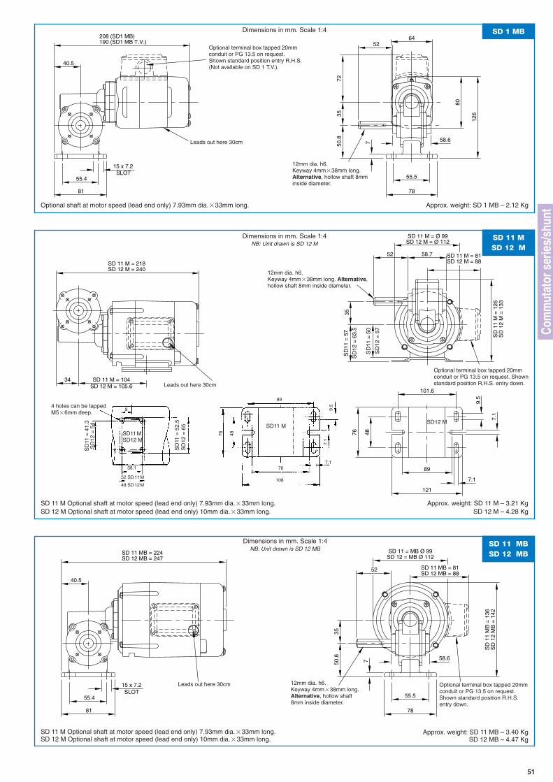
34
SD 11 M = 218SD 12 M = 240
SD 11 M = 104SD 12 M = 105.6
7.19.
5
7.1
101.6
89
48
121
7635
58.752
SD 11 M = Ø 99SD 12 M = Ø 112
SD 11 M = 81SD 12 M = 88
SD
11 =
57
SD
11 =
50
SD
11
M =
126
SD
12
M =
133
SD
12 =
57
SD
12 =
63.
5
208 (SD1 MB) 64
80
190 (SD1 MB T.V.) 52
126
7 58.6
3550
.8
78
55.5SLOT
81
15 x 7.2
55.4
40.5
72
SD 1 MBDimensions in mm. Scale 1:4
Optional shaft at motor speed (lead end only) 7.93mm dia.�33mm long. Approx. weight: SD 1 MB – 2.12 Kg
Leads out here 30cm
Optional terminal box tapped 20mmconduit or PG 13.5 on request.Shown standard position entry R.H.S.(Not available on SD 1 T.V.).
12mm dia. h6.Keyway 4mm�38mm long.Alternative, hollow shaft 8mminside diameter.
SD 11 MSD 12 M
Dimensions in mm. Scale 1:4NB: Unit drawn is SD 12 M
SD 11 M Optional shaft at motor speed (lead end only) 7.93mm dia.�33mm long. Approx. weight: SD 11 M – 3.21 Kg
Leads out here 30cm
12mm dia. h6.Keyway 4mm�38mm long. Alternative,hollow shaft 8mm inside diameter.
SD
11
MB
= 1
36
SD 11 = MB Ø 99SD 12 = MB Ø 112
SD 11 MB = 224SD 12 MB = 247
52
SD
12
MB
= 1
42
7 58.6
3550
.8
78
55.5SLOT
81
15 x 7.2
55.4
40.5
SD 11 MB = 81SD 12 MB = 88
SD 11 MBSD 12 MB
Dimensions in mm. Scale 1:4NB: Unit drawn is SD 12 MB
SD 11 M Optional shaft at motor speed (lead end only) 7.93mm dia.�33mm long.SD 12 M Optional shaft at motor speed (lead end only) 10mm dia.�33mm long.
Approx. weight: SD 11 MB – 3.40 KgSD 12 MB – 4.47 Kg
Leads out here 30cm Optional terminal box tapped 20mmconduit or PG 13.5 on request.Shown standard position R.H.S.entry down.
12mm dia. h6.Keyway 4mm�38mm long.Alternative, hollow shaft8mm inside diameter.
51
SD 12 M Optional shaft at motor speed (lead end only) 10mm dia.�33mm long. SD 12 M – 4.28 Kg
4 holes can be tappedM5�6mm deep.
SD12 M
SD11MSD12 M
SD11 M
8
38.1
SD
11 =
52.
5S
D12
= 6
5
89
76 48
9.5
7.1
7.176
10852 SD11M
48 SD12M
SD
11 =
41.
3S
D12
= 5
4
Com
mut
ator
ser
ies/
shun
t
Optional terminal box tapped 20mmconduit or PG 13.5 on request. Shownstandard position R.H.S. entry down.
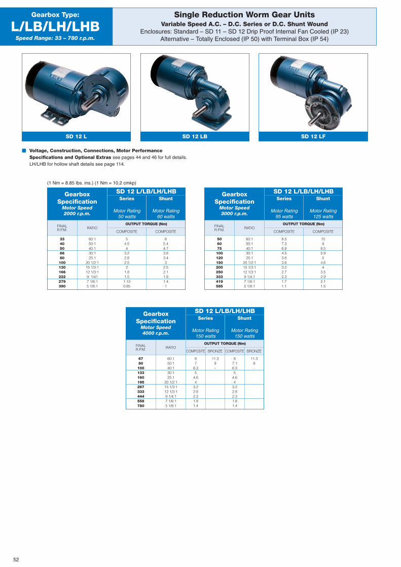
109
8.55.95
4.64
3.52.92.11.5
11.39-
11.39–
COMPOSITE
OUTPUT TORQUE (Nm)FINALR.P.M. COMPOSITE
RATIO
Single Reduction Worm Gear UnitsVariable Speed A.C. – D.C. Series or D.C. Shunt Wound
Enclosures: Standard – SD 11 – SD 12 Drip Proof Internal Fan Cooled (IP 23)Alternative – Totally Enclosed (IP 50) with Terminal Box (IP 54)
Gearbox Type:
L/LB/LH/LHBSpeed Range: 33 – 780 r.p.m.
SD 12 L
� Voltage, Construction, Connections, Motor PerformanceSpecifications and Optional Extras see pages 44 and 46 for full details.LH/LHB for hollow shaft details see page 114.
(1 Nm = 8.85 lbs. ins.) (1 Nm = 10.2 cmkp)
GearboxSpecification
Motor Speed2000 r.p.m.
Series
Motor Rating50 watts
SD 12 L/LB/LH/LHBShunt
Motor Rating60 watts
3340506680100130166222279390
60:150:140:130:125:1
20 1/2:115 1/3:112 1/3:19: 1/417 1/6:15 1/8:1
54.54
3.22.82.52
1.81.51.130.85
65.44.73.83.43
2.52.11.81.41
COMPOSITE
OUTPUT TORQUE (Nm)FINALR.P.M. COMPOSITE
RATIO
GearboxSpecification
Motor Speed3000 r.p.m.
Series
Motor Rating95 watts
SD 12 L/LB/LH/LHBShunt
Motor Rating125 watts
506075100120150200250333419585
60:150:140:130:125:1
20 1/2:115 1/3:112 1/3:19 1/4:17 1/6:15 1/8:1
8.57.36.84.53.83.63.22.72.31.71.1
COMPOSITE BRONZE
OUTPUT TORQUE (Nm)FINALR.P.M. COMPOSITE BRONZE
RATIO
GearboxSpecification
Motor Speed4000 r.p.m.
Series
Motor Rating150 watts
SD 12 L/LB/LH/LHBShunt
Motor Rating150 watts
6780100133160195267333444558780
60:150:140:130:125:1
20 1/2:115 1/3:112 1/3:19 1/4:17 1/6:15 1/8:1
87
6.35
4.64
3.22.82.31.81.4
87.16.35
4.64
3.22.82.31.81.4
SD 12 LFSD 12 LB
52
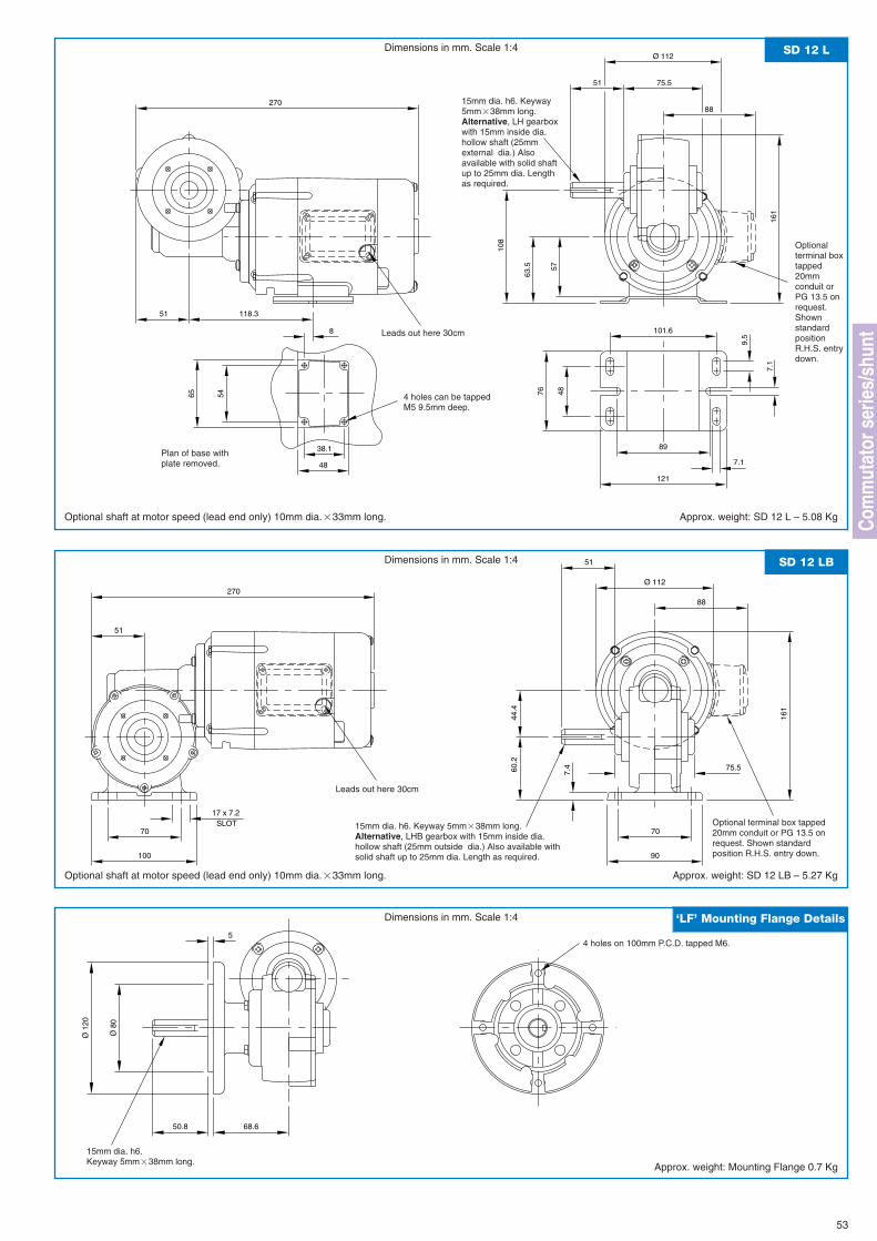
Ø 112
51
51 75.5
270
108
161
8 101.6
9.5
57
7.1
7.1
48
89
121
63.5
76
38.1
48
5465
118.3
88
SD 12 LDimensions in mm. Scale 1:4
Optional shaft at motor speed (lead end only) 10mm dia.�33mm long. Approx. weight: SD 12 L – 5.08 Kg
Leads out here 30cm
Plan of base withplate removed.
Optionalterminal boxtapped20mmconduit orPG 13.5 onrequest.ShownstandardpositionR.H.S. entrydown.
15mm dia. h6. Keyway5mm�38mm long.Alternative, LH gearboxwith 15mm inside dia.hollow shaft (25mmexternal dia.) Alsoavailable with solid shaftup to 25mm dia. Lengthas required.
4 holes can be tappedM5 9.5mm deep.
53
Ø 112
75.5
51
60.2
70
90
7.4
44.4
161
51
SLOT70
17 x 7.2
100
27088
SD 12 LBDimensions in mm. Scale 1:4
Optional shaft at motor speed (lead end only) 10mm dia.�33mm long. Approx. weight: SD 12 LB – 5.27 Kg
Leads out here 30cm
Optional terminal box tapped20mm conduit or PG 13.5 onrequest. Shown standardposition R.H.S. entry down.
15mm dia. h6. Keyway 5mm�38mm long.Alternative, LHB gearbox with 15mm inside dia.hollow shaft (25mm outside dia.) Also available withsolid shaft up to 25mm dia. Length as required.
Ø 1
20
Ø 8
0
5
50.8 68.6
15mm dia. h6.Keyway 5mm�38mm long.
‘LF’ Mounting Flange Details
Approx. weight: Mounting Flange 0.7 Kg
Dimensions in mm. Scale 1:4
Com
mut
ator
ser
ies/
shun
t
4 holes on 100mm P.C.D. tapped M6.
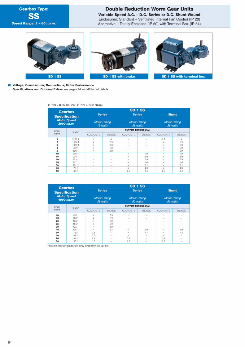
OUTPUT TORQUE (Nm)
BRONZE
FINALR.P.M. COMPOSITE COMPOSITE COMPOSITEBRONZE BRONZE
*RATIO
Double Reduction Worm Gear UnitsVariable Speed A.C. – D.C. Series or D.C. Shunt WoundEnclosures: Standard – Ventilated Internal Fan Cooled (IP 20)Alternative – Totally Enclosed (IP 50) with Terminal Box (IP 54)
Gearbox Type:
SSSpeed Range: 1 – 80 r.p.m.
SD 1 SS SD 1 SS with brake
� Voltage, Construction, Connections, Motor PerformanceSpecifications and Optional Extras see pages 44 and 46 for full details.
(1 Nm = 8.85 lbs. ins.) (1 Nm = 10.2 cmkp)
GearboxSpecification
Motor Speed3000 r.p.m.
Series
Motor Rating15 watts
Series
Motor Rating38 watts
Shunt
Motor Rating38 watts
SD 1 SS
SD 1 SS with terminal box
1234510152025304050
3168:11584:11023:1792:1620:1306:1204:1153:1127:1101:178:165:1
–4444–––––––
45.95.95.95.9–––––––
–––––444444
3.4
–––––
5.95.95.95.65.14.33.4
2.74444444444
3.4
45.95.95.95.95.95.95.95.65.14.33.4
OUTPUT TORQUE (Nm)
BRONZE
FINALR.P.M. COMPOSITE COMPOSITE COMPOSITEBRONZE BRONZE
*RATIO
GearboxSpecification
Motor Speed4000 r.p.m.
Series
Motor Rating38 watts
Series
Motor Rating50 watts
Shunt
Motor Rating50 watts
SD 1 SS
10152025304050607080
405:1268:1196:1164:1135:1105:175:168:158:150:1
444444
2.82.62.11.8
5.95.95.95.95.95.1––––
–––––444
3.42.8
–––––
5.94.1–––
–––––444
3.42.8
–––––
5.94.2–––
*Ratios are for guidance only and may be varied.
54

25.4
64
200 (SD1 SS)
80
182 (SD1 SS T.V.)
2944
2847.3
29
47
9.5
50.8
98.8 (SD1 SS)
28.6
22.2
5.6
7.1
70
5.6
59
84
46
51
80.9 (SD1 SS T.V.)
38
32
32
105
SD 1 SSDimensions in mm. Scale 1:4
Optional shaft at motor speed (lead end only) 7.93mm dia.�33mm long. Approx. weight: SD 1 SS – 2.03 Kg
Leads out here 30cm
55
Optional terminal box tapped 20mmconduit or PG 13.5 on request.Shown standard position entryR.H.S. (Not available on SD 1 T.V.)
4 holes can be tapped M4�9mm deep.
9mm dia. h6.Flat 6mm�19mm long.
Com
mut
ator
ser
ies/
shun
tPlan of base withplate removed.
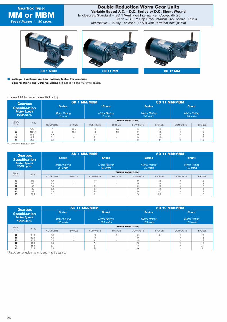
BRONZE
OUTPUT TORQUE (Nm)FINALR.P.M. COMPOSITE COMPOSITE COMPOSITE COMPOSITEBRONZE BRONZE BRONZE
*RATIO
Double Reduction Worm Gear UnitsVariable Speed A.C. – D.C. Series or D.C. Shunt Wound
Enclosures: Standard – SD 1 Ventilated Internal Fan Cooled (IP 20)SD 11 – SD 12 Drip Proof Internal Fan Cooled (IP 23)
Alternative – Totally Enclosed (IP 50) with Terminal Box (IP 54)
Gearbox Type:
MM or MBMSpeed Range: 1 – 80 r.p.m.
SD 1 MBM SD 11 MM
� Voltage, Construction, Connections, Motor PerformanceSpecifications and Optional Extras see pages 44 and 46 for full details.
(1 Nm = 8.85 lbs. ins.) (1 Nm = 10.2 cmkp)
†Maximum voltage 120V D.C.
GearboxSpecification
Motor Speed2000 r.p.m.
Series
Motor Rating10 watts
†Shunt
Motor Rating10 watts
Series
Motor Rating30 watts
Shunt
Motor Rating50 watts
SD 1 MM/MBM SD 11 MM/MBM
12358
2480:11296:1675:1412:1258:1
99
7.95.13.4
11.811.8
–––
99
7.95.13.4
11.811.8
–––
99999
11.811.811.811.810.1
99999
11.811.811.811.811.8
BRONZE
OUTPUT TORQUE (Nm)FINALR.P.M. COMPOSITE COMPOSITE COMPOSITE COMPOSITEBRONZE BRONZE BRONZE
*RATIO
GearboxSpecification
Motor Speed3000 r.p.m.
Series
Motor Rating38 watts
Shunt
Motor Rating38 watts
Series
Motor Rating75 watts
Shunt
Motor Rating95 watts
SD 1 MM/MBM SD 11 MM/MBM
101520253035
308:1225:1150:1120:1107:186:1
7.97.36.86.25.65.1
–––
7.97.36.86.25.65.1
–––
999999
11.811.811.811.810.79.6
999999
11.811.811.811.811.811.8
*Ratios are for guidance only and may be varied.
BRONZE
OUTPUT TORQUE (Nm)FINALR.P.M. COMPOSITE COMPOSITE COMPOSITE COMPOSITEBRONZE BRONZE BRONZE
*RATIO
GearboxSpecification
Motor Speed4000 r.p.m.
Series
Motor Rating95 watts
Shunt
Motor Rating125 watts
Series
Motor Rating125 watts
Shunt
Motor Rating150 watts
SD 11 MM/MBM SD 12 MM/MBM
404550607080
94:189:182:168:158:151:1
7.97.36.85.65.14.5
–––
99
8.57.96.85.6
10.1––
99
8.57.96.85.6
10.1–––––
999999
11.811.811.811.39.69
SD 12 MM
56
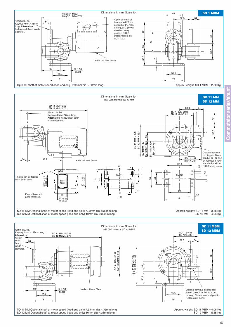
101.6
9.5
7.1
7.1
48
89
121
76
34
SD 11 MM = 253SD 12 MM = 276
138.9
5258
.7
3462.3
SD 12 MM Ø 112
35
SD 11 MM Ø 99
SD
12M
M =
57
SD
12M
M =
63.
5
SD
11
MM
= 1
26
SD
12
MM
= 1
33
SD
11M
M =
57
SD
11M
M =
50.
6
SD 11 = 81SD 12 = 88
80
5258
.7
3462.3
69SLOT
81
15 x 7.2
55.4
34
236 (SD1 MBM) 64218 (SD1 MBM T.V.)
7
3550
.8
78
55.5
72
SD 1 MBMDimensions in mm. Scale 1:4
Optional shaft at motor speed (lead end only) 7.93mm dia.�33mm long. Approx. weight: SD 1 MBM – 2.80 Kg
Leads out here 30cm
12mm dia. h6.Keyway 4mm�38mmlong. Alternative,hollow shaft 8mm insidediameter.
Optional terminalbox tapped 20mmconduit or PG 13.5on request. Shownstandard entryposition R.H.S.(Not available onSD 1 T.V.).
SD 11 MMSD 12 MM
Dimensions in mm. Scale 1:4NB: Unit drawn is SD 12 MM
SD 11 MM Optional shaft at motor speed (lead end only) 7.93mm dia.�33mm long.SD 12 MM Optional shaft at motor speed (lead end only) 10mm dia.�33mm long.
Approx. weight: SD 11 MM – 3.88 KgSD 12 MM – 4.95 Kg
Leads out here 30cm
12mm dia. h6.Keyway 4mm�38mm long.Alternative, hollow shaft 8mminside diameter.
Optional terminalbox tapped 20mmconduit or PG 13.5on request. Shownstandard positionR.H.S. entry down.
SD
11
MB
M Ø
99
SD
12
MB
M Ø
112
SD
11
MB
M =
136
SD
12
MB
M =
142 52
58.7
3462.3
69SLOT
81
15 x 7.2
55.4
34
SD 11 MBM = 253SD 12 MBM = 276
7
3550
.8
78
55.5
SD 11c = 81SD 12c = 88
SD 11 MBMSD 12 MBM
Dimensions in mm. Scale 1:4NB: Unit drawn is SD 12 MBM
SD 11 MM Optional shaft at motor speed (lead end only) 7.93mm dia.�33mm long.SD 12 MM Optional shaft at motor speed (lead end only) 10mm dia.�33mm long.
Approx. weight: SD 11 MBM – 4.08 KgSD 12 MBM – 5.15 Kg
Leads out here 30cm
12mm dia. h6.Keyway 4mm � 38mm long.Alternative,hollowshaft8mminsidediameter.
Optional terminal box tapped20mm conduit or PG 13.5 onrequest. Shown standard positionR.H.S. entry down.
57
SD11SD12
8
SD
11 =
41.
3S
D12
= 5
4
38.1
SD
11 =
53
SD
12 =
65
89
76
9.5
7.1
7.1
SD 11 52SD 12 48
Plan of base withplate removed.
48
SD 11 SD 12
76
108
4 holes can be tappedM5�6mm deep.
Com
mut
ator
ser
ies/
shun
t
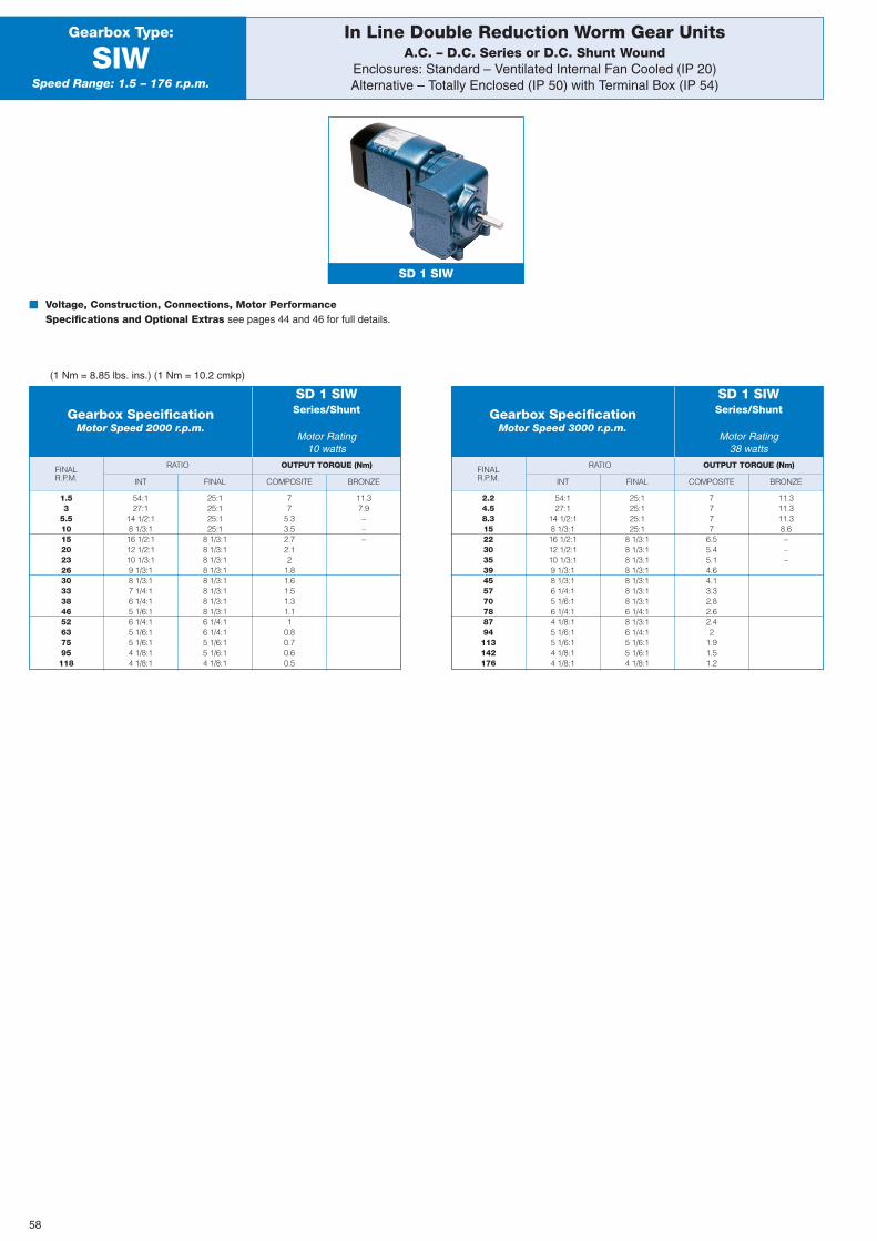
BRONZE
OUTPUT TORQUE (Nm)FINALR.P.M.
In Line Double Reduction Worm Gear UnitsA.C. – D.C. Series or D.C. Shunt Wound
Enclosures: Standard – Ventilated Internal Fan Cooled (IP 20)Alternative – Totally Enclosed (IP 50) with Terminal Box (IP 54)
Gearbox Type:
SIWSpeed Range: 1.5 – 176 r.p.m.
� Voltage, Construction, Connections, Motor PerformanceSpecifications and Optional Extras see pages 44 and 46 for full details.
SD 1 SIW
INT FINAL COMPOSITE
RATIO
Gearbox SpecificationMotor Speed 2000 r.p.m.
Series/Shunt
Motor Rating10 watts
SD 1 SIW
1.53
5.510152023263033384652637595118
54:127:1
14 1/2:18 1/3:116 1/2:112 1/2:110 1/3:19 1/3:18 1/3:17 1/4:16 1/4:15 1/6:16 1/4:15 1/6:15 1/6:14 1/8:14 1/8:1
25:125:125:125:1
8 1/3:18 1/3:18 1/3:18 1/3:18 1/3:18 1/3:18 1/3:18 1/3:16 1/4:16 1/4:15 1/6:15 1/6:14 1/8:1
77
5.33.52.72.12
1.81.61.51.31.11
0.80.70.60.5
11.37.9–––
BRONZE
OUTPUT TORQUE (Nm)FINALR.P.M. INT FINAL COMPOSITE
RATIO
Gearbox SpecificationMotor Speed 3000 r.p.m.
Series/Shunt
Motor Rating38 watts
SD 1 SIW
2.24.58.31522303539455770788794113142176
54:127:1
14 1/2:18 1/3:116 1/2:112 1/2:110 1/3:19 1/3:18 1/3:16 1/4:15 1/6:16 1/4:14 1/8:15 1/6:15 1/6:14 1/8:14 1/8:1
25:125:125:125:1
8 1/3:18 1/3:18 1/3:18 1/3:18 1/3:18 1/3:18 1/3:16 1/4:18 1/3:16 1/4:15 1/6:15 1/6:14 1/8:1
7777
6.55.45.14.64.13.32.82.62.42
1.91.51.2
11.311.311.38.6–––
(1 Nm = 8.85 lbs. ins.) (1 Nm = 10.2 cmkp)
58
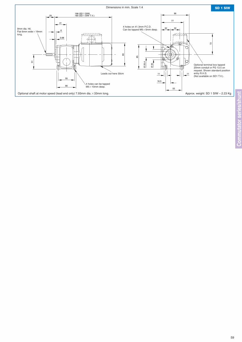
80
198 (SD 1 SIW)
3232
77
96
41
6
3.68
85
Ø 2
0.4
Ø 3
5
66
5516.5
55
1111
180 (SD 1 SIW T.V.)29
51
72
SD 1 SIWDimensions in mm. Scale 1:4
Optional shaft at motor speed (lead end only) 7.93mm dia.�33mm long. Approx. weight: SD 1 SIW – 2.23 Kg
Leads out here 30cm
Optional terminal box tapped20mm conduit or PG 13.5 onrequest. Shown standard positionentry R.H.S.(Not available on SD1 T.V.).
4 holes can be tappedM5�10mm deep.
4 holes on 41.3mm P.C.D.Can be tapped M5�5mm deep.9mm dia. h6.
Flat 6mm wide�19mmlong.
59
Com
mut
ator
ser
ies/
shun
t
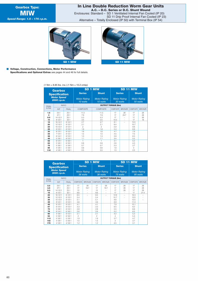
BRONZE
In Line Double Reduction Worm Gear UnitsA.C. – D.C. Series or D.C. Shunt Wound
Enclosures: Standard – SD 1 Ventilated Internal Fan Cooled (IP 20)SD 11 Drip Proof Internal Fan Cooled (IP 23)
Alternative – Totally Enclosed (IP 50) with Terminal Box (IP 54)
Gearbox Type:
MIWSpeed Range: 1.5 – 176 r.p.m.
SD 1 MIW
� Voltage, Construction, Connections, Motor PerformanceSpecifications and Optional Extras see pages 44 and 46 for full details.
OUTPUT TORQUE (Nm)FINALR.P.M. COMPOSITE COMPOSITE COMPOSITE BRONZE COMPOSITE
RATIO
INT FINAL
(1 Nm = 8.85 lbs. ins.) (1 Nm = 10.2 cmkp)
GearboxSpecification
Motor Speed2000 r.p.m.
Series
Motor Rating10 watts
Shunt
Motor Rating10 watts
Series
Motor Rating30 watts
Shunt
Motor Rating50 watts
SD 1 MIW SD 11 MIW
1.53
5.510152023263033384652637595118
54:127:1
14 1/2:18 1/3:116 1/2:112 1/2:110 1/3:19 1/3:18 1/3:17 1/4:16 1/4:15 1/6:16 1/4:15 1/6:15 1/6:14 1/8:14 1/8:1
25:125:125:125:1
8 1/3:18 1/3:18 1/3:18 1/3:18 1/3:18 1/3:18 1/3:18 1/3:16 1/6:16 1/6:15 1/8:15 1/8:14 1/8:1
11.37.95.33.52.72.12
1.81.61.51.31.11
0.80.70.60.5
11.37.95.33.52.72.12
1.81.61.51.31.11
0.80.70.60.5
171717
10.58.16.45.95.34.74.53.93.43.12.62.31.81.5
2823.7
–––
17171717
13.510.79.88.97.97.56.55.55.24.33.73
2.5
28282618
BRONZE
OUTPUT TORQUE (Nm)FINALR.P.M. COMPOSITECOMPOSITECOMPOSITE BRONZEBRONZEBRONZE COMPOSITE
RATIO
INT FINAL
GearboxSpecification
Motor Speed3000 r.p.m.
Series
Motor Rating38 watts
Shunt
Motor Rating38 watts
Series
Motor Rating75 watts
Shunt
Motor Rating95 watts
SD 1 MIW SD 11 MIW
2.24.58.31522303539455770789094113142176
54:127:1
14 1/2:18 1/3:116 1/2:112 1/2:110 1/3:19 1/3:18 1/3:16 1/4:15 1/6:16 1/4:14 1/8:15 1/6:15 1/6:14 1/8:14 1/8:1
25:125:125:125:1
8 1/3:18 1/3:18 1/3:18 1/3:18 1/3:18 1/3:18 1/3:16 1/6:18 1/3:16 1/6:15 1/8:15 1/8:14 1/8:1
1717138.66.55.45.14.64.13.32.82.62.12
1.91.51.2
2819.7
–––
1717138.66.55.45.14.64.13.32.82.62.12
1.91.51.2
2819.7
–––
17171717
12.810.79.88.97.96.55.55.24.24
3.73
2.5
282828–––
17171717
16.313.512.511.310.18.26.86.55.35.44.73.73.1
282828
21.4–––
SD 11 MIW
60
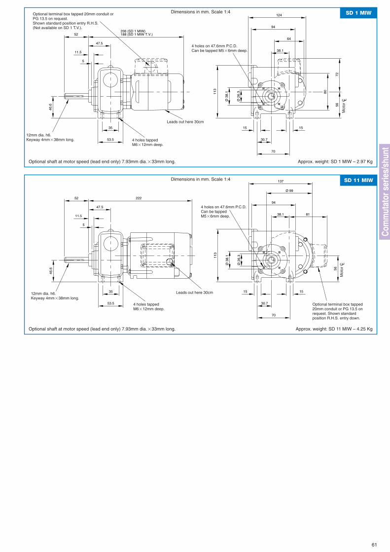
64
80
124
94
38.1
56
113
Ø 2
6.3
Ø 3
8.1
5
11.5
47.5
15
70
30.7
15
46.6
53.5
35
206 (SD 1 MIW)188 (SD 1 MIW T.V.)52
72
SD 1 MIWDimensions in mm. Scale 1:4
Optional shaft at motor speed (lead end only) 7.93mm dia.�33mm long. Approx. weight: SD 1 MIW – 2.97 Kg
Leads out here 30cm
12mm dia. h6.Keyway 4mm�38mm long.
4 holes on 47.6mm P.C.D.Can be tapped M5�6mm deep.
Optional terminal box tapped 20mm conduit orPG 13.5 on request.Shown standard position entry R.H.S.(Not available on SD 1 T.V.).
4 holes tappedM6�12mm deep.
Ø 99
137
94
38.1
56
113
Ø 2
6.3
Ø 3
8.1
5
11.5
47.5
15
70
30.7
15
46.6
53.5
35
22252
81
SD 11 MIWDimensions in mm. Scale 1:4
Optional shaft at motor speed (lead end only) 7.93mm dia.�33mm long. Approx. weight: SD 11 MIW – 4.25 Kg
Leads out here 30cm
Optional terminal box tapped20mm conduit or PG 13.5 onrequest. Shown standardposition R.H.S. entry down.
12mm dia. h6.Keyway 4mm�38mm long.
4 holes tappedM6�12mm deep.
4 holes on 47.6mm P.C.D.Can be tappedM5�6mm deep.
61
Com
mut
ator
ser
ies/
shun
t
Mot
or C L
Mot
or C L
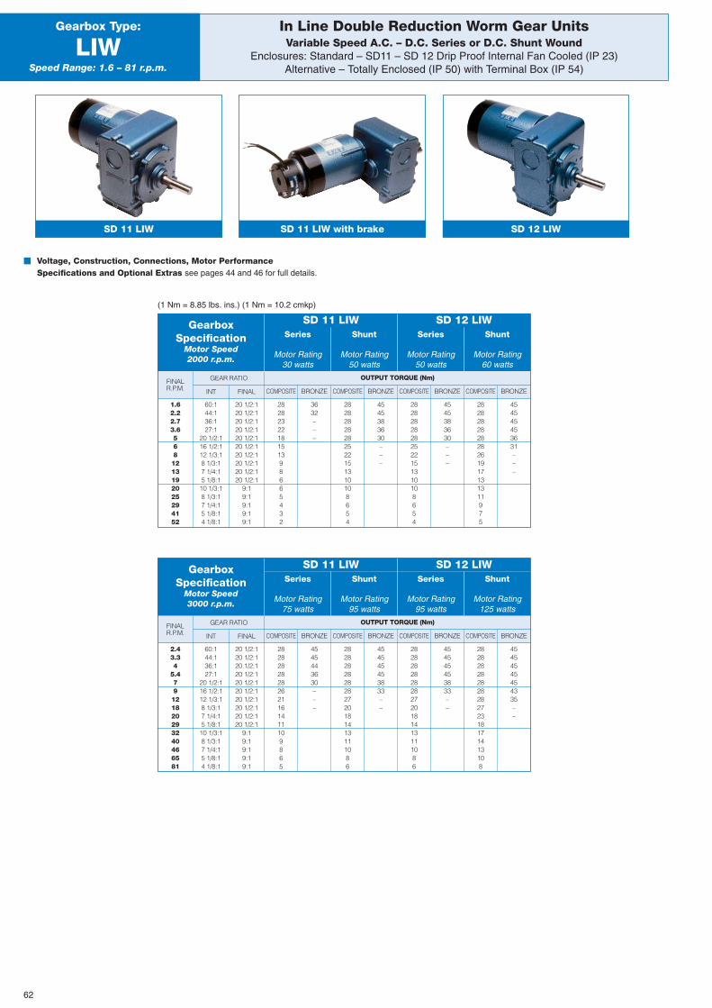
In Line Double Reduction Worm Gear UnitsVariable Speed A.C. – D.C. Series or D.C. Shunt Wound
Enclosures: Standard – SD11 – SD 12 Drip Proof Internal Fan Cooled (IP 23)Alternative – Totally Enclosed (IP 50) with Terminal Box (IP 54)
Gearbox Type:
LIWSpeed Range: 1.6 – 81 r.p.m.
� Voltage, Construction, Connections, Motor PerformanceSpecifications and Optional Extras see pages 44 and 46 for full details.
(1 Nm = 8.85 lbs. ins.) (1 Nm = 10.2 cmkp)
BRONZE
OUTPUT TORQUE (Nm)FINALR.P.M. COMPOSITECOMPOSITECOMPOSITE BRONZEBRONZEBRONZE COMPOSITE
GEAR RATIO
INT FINAL
GearboxSpecification
Motor Speed2000 r.p.m.
Series
Motor Rating30 watts
Shunt
Motor Rating50 watts
Series
Motor Rating50 watts
Shunt
Motor Rating60 watts
SD 11 LIW SD 12 LIW
1.62.22.73.65681213192025294152
60:144:136:127:1
20 1/2:116 1/2:112 1/3:18 1/3:17 1/4:15 1/8:110 1/3:18 1/3:17 1/4:15 1/8:14 1/8:1
20 1/2:120 1/2:120 1/2:120 1/2:120 1/2:120 1/2:120 1/2:120 1/2:120 1/2:120 1/2:1
9:19:19:19:19:1
2828232218151398665432
3632–––
28282828282522151310108654
4545383630–––
28282828282522151310108654
4545383630–––
282828282828261917131311975
454545453631–––
BRONZE
OUTPUT TORQUE (Nm)FINALR.P.M. COMPOSITECOMPOSITECOMPOSITE BRONZEBRONZEBRONZE COMPOSITE
GEAR RATIO
INT FINAL
GearboxSpecification
Motor Speed3000 r.p.m.
Series
Motor Rating75 watts
Shunt
Motor Rating95 watts
Series
Motor Rating95 watts
Shunt
Motor Rating125 watts
SD 11 LIW SD 12 LIW
2.43.34
5.479121820293240466581
60:144:136:127:1
20 1/2:116 1/2:112 1/3:18 1/3:17 1/4:15 1/8:110 1/3:18 1/3:17 1/4:15 1/8:14 1/8:1
20 1/2:120 1/2:120 1/2:120 1/2:120 1/2:120 1/2:120 1/2:120 1/2:120 1/2:120 1/2:1
9:19:19:19:19:1
28282828282621161411109865
4545443630–––
2828282828282720181413111086
454545453833––
2828282828282720181413111086
454545453833––
28282828282828272318171413108
45454545454335––
SD 11 LIW with brakeSD 11 LIW SD 12 LIW
62
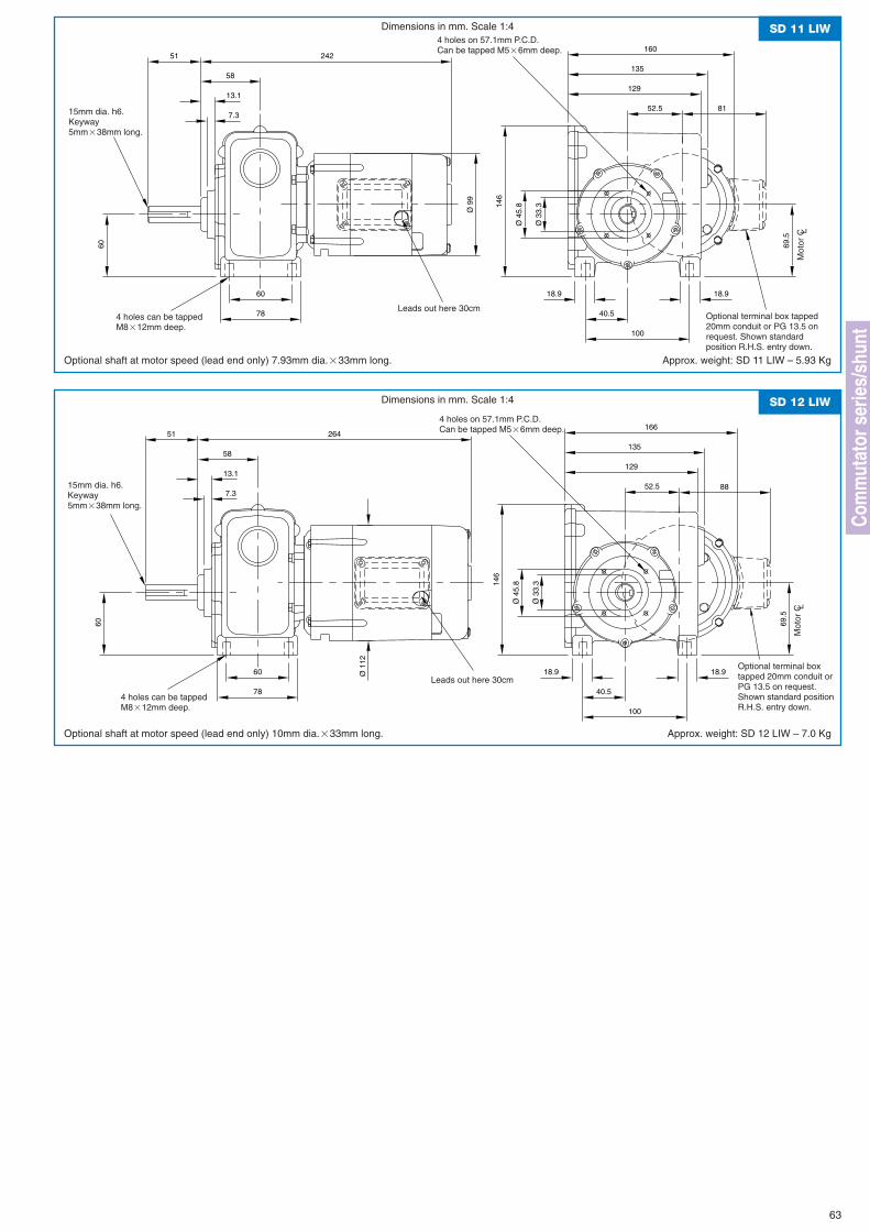
Ø 9
9
129
135
160
52.5
146
Ø 4
5.8
Ø 3
3.3
69.5
18.918.9
40.5
100
58
13.1
7.3
78
60
51
60
242
81
SD 11 LIWDimensions in mm. Scale 1:4
Optional shaft at motor speed (lead end only) 7.93mm dia.�33mm long. Approx. weight: SD 11 LIW – 5.93 Kg
Leads out here 30cm
15mm dia. h6.Keyway5mm�38mm long.
4 holes can be tappedM8�12mm deep.
Ø 1
12
129
135
166
52.514
6
Ø 4
5.8
Ø 3
3.3
69.5
18.918.9
40.5
100
58
13.1
7.3
78
60
51
60
264
88
SD 12 LIWDimensions in mm. Scale 1:4
Optional shaft at motor speed (lead end only) 10mm dia.�33mm long. Approx. weight: SD 12 LIW – 7.0 Kg
Leads out here 30cm
15mm dia. h6.Keyway5mm�38mm long.
4 holes can be tappedM8�12mm deep.
4 holes on 57.1mm P.C.D.Can be tapped M5�6mm deep.
Optional terminal box tapped20mm conduit or PG 13.5 onrequest. Shown standardposition R.H.S. entry down.
4 holes on 57.1mm P.C.D.Can be tapped M5�6mm deep.
Optional terminal boxtapped 20mm conduit orPG 13.5 on request.Shown standard positionR.H.S. entry down.
63
Com
mut
ator
ser
ies/
shun
t
Mot
or C L
Mot
or C L
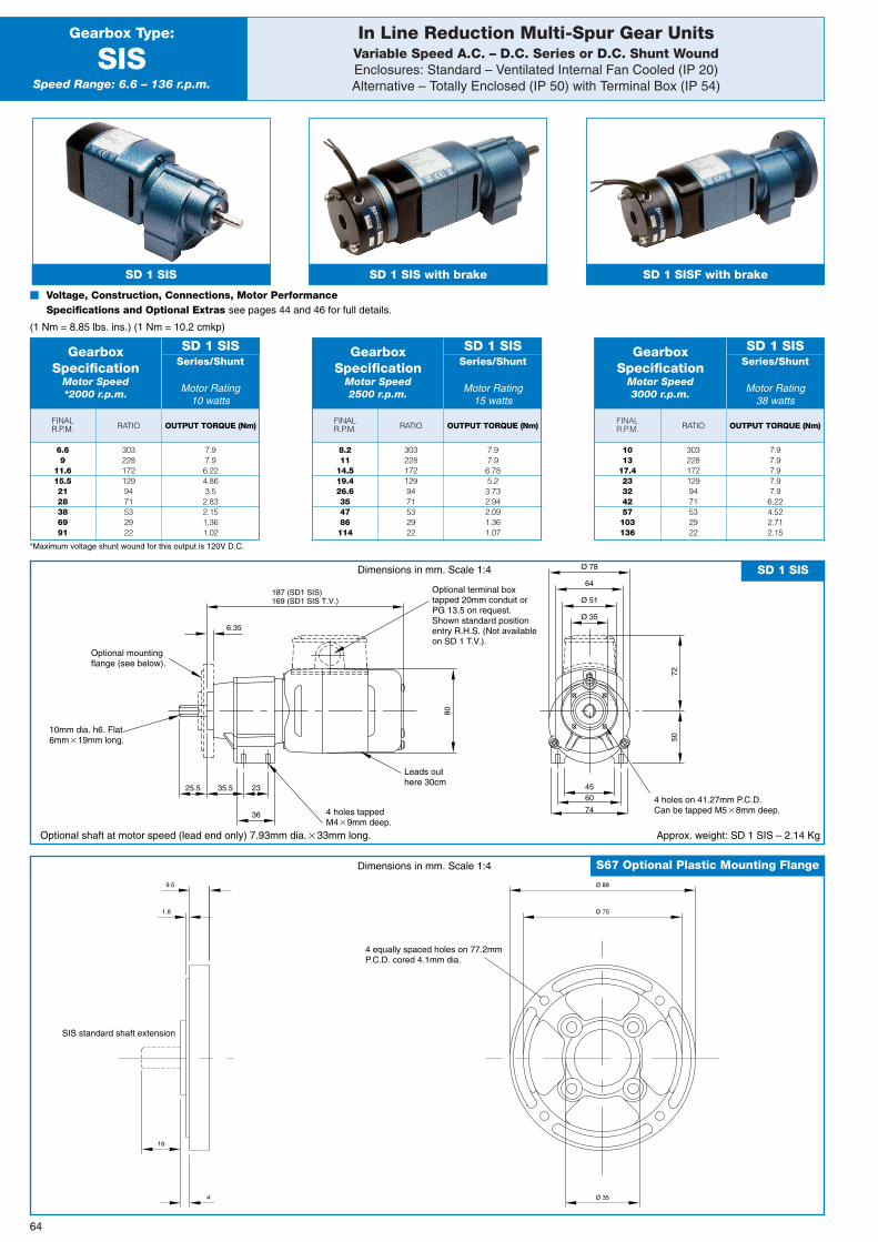
In Line Reduction Multi-Spur Gear UnitsVariable Speed A.C. – D.C. Series or D.C. Shunt WoundEnclosures: Standard – Ventilated Internal Fan Cooled (IP 20)Alternative – Totally Enclosed (IP 50) with Terminal Box (IP 54)
Gearbox Type:
SISSpeed Range: 6.6 – 136 r.p.m.
SD 1 SIS SD 1 SIS with brake
� Voltage, Construction, Connections, Motor PerformanceSpecifications and Optional Extras see pages 44 and 46 for full details.
(1 Nm = 8.85 lbs. ins.) (1 Nm = 10.2 cmkp)
*Maximum voltage shunt wound for this output is 120V D.C.
SD 1 SISF with brake
64
FINALR.P.M. OUTPUT TORQUE (Nm)OUTPUT TORQUE (Nm)
FINALR.P.M. RATIO
GearboxSpecification
Motor Speed*2000 r.p.m.
Series/Shunt
Motor Rating10 watts
SD 1 SIS
6.69
11.615.52128386991
3032281721299471532922
7.97.96.224.863.52.832.151.361.02
OUTPUT TORQUE (Nm)FINALR.P.M. RATIO
GearboxSpecification
Motor Speed2500 r.p.m.
Series/Shunt
Motor Rating15 watts
SD 1 SIS
8.211
14.519.426.6354786114
3032281721299471532922
7.97.96.785.23.732.942.091.361.07
RATIO
GearboxSpecification
Motor Speed3000 r.p.m.
Series/Shunt
Motor Rating38 watts
SD 1 SIS
1013
17.423324257103136
3032281721299471532922
7.97.97.97.97.96.224.522.712.15
4
18
1.8
9.5
Ø 35
Ø 88
Ø 75
S67 Optional Plastic Mounting FlangeDimensions in mm. Scale 1:4
80
64187 (SD1 SIS)169 (SD1 SIS T.V.)
Ø 78
4560
74
50
Ø 51
Ø 35
36
25.5 35.5 23
6.35
72
SD 1 SISDimensions in mm. Scale 1:4
10mm dia. h6. Flat6mm�19mm long.
Optional mountingflange (see below).
Optional terminal boxtapped 20mm conduit orPG 13.5 on request.Shown standard positionentry R.H.S. (Not availableon SD 1 T.V.).
Leads outhere 30cm
4 holes tappedM4�9mm deep.
4 equally spaced holes on 77.2mmP.C.D. cored 4.1mm dia.
SIS standard shaft extension
4 holes on 41.27mm P.C.D.Can be tapped M5�8mm deep.
Approx. weight: SD 1 SIS – 2.14 KgOptional shaft at motor speed (lead end only) 7.93mm dia.�33mm long.
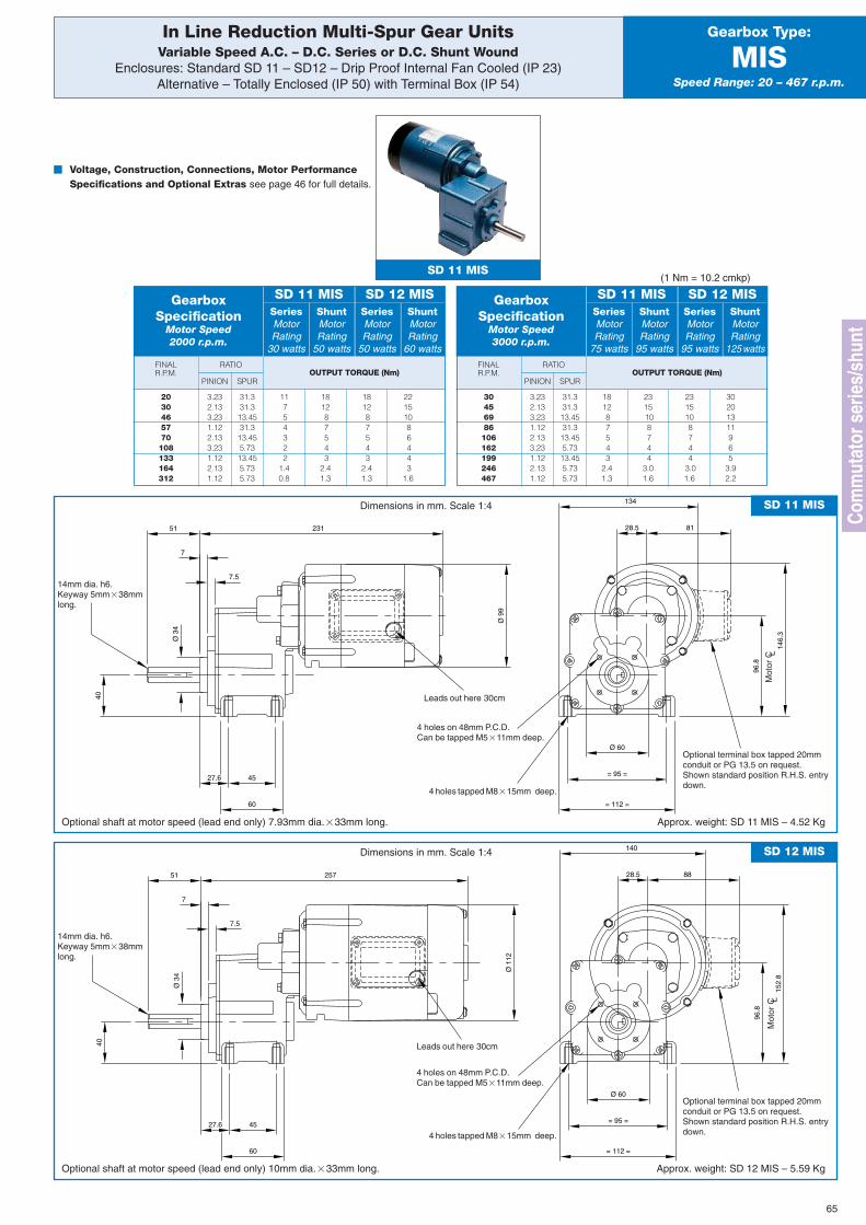
In Line Reduction Multi-Spur Gear UnitsVariable Speed A.C. – D.C. Series or D.C. Shunt Wound
Enclosures: Standard SD 11 – SD12 – Drip Proof Internal Fan Cooled (IP 23)Alternative – Totally Enclosed (IP 50) with Terminal Box (IP 54)
Gearbox Type:
MISSpeed Range: 20 – 467 r.p.m.
(1 Nm = 10.2 cmkp)
FINALR.P.M. OUTPUT TORQUE (Nm)
PINION
RATIO
SPUR
GearboxSpecification
Motor Speed2000 r.p.m.
SeriesMotorRating
30 watts
ShuntMotorRating
50 watts
SeriesMotorRating
50 watts
ShuntMotorRating
60 watts
SD 11 MIS SD 12 MIS
2030465770108133164312
3.232.133.231.122.133.231.122.131.12
31.331.313.4531.313.455.7313.455.735.73
11754322
1.40.8
181287543
2.41.3
181287543
2.41.3
22151086443
1.6
65
FINALR.P.M. OUTPUT TORQUE (Nm)
PINION
RATIO
SPUR
GearboxSpecification
Motor Speed3000 r.p.m.
SeriesMotorRating
75 watts
ShuntMotorRating
95 watts
SeriesMotorRating
95 watts
ShuntMotorRating
125watts
SD 11 MIS SD 12 MIS
30456986106162199246467
3.232.133.231.122.133.231.122.131.12
31.331.313.4531.313.455.7313.455.735.73
181287543
2.41.3
2315108744
3.01.6
2315108744
3.01.6
30201311965
3.92.2
Ø 9
9
96.8
28.5
27.6
231
7
7.5
51
Ø 3
4
40
Ø 60
= 95 =
= 112 =60
45
134
146.
3
81
SD 11 MISDimensions in mm. Scale 1:4
14mm dia. h6.Keyway 5mm�38mmlong.
4 holes on 48mm P.C.D.Can be tapped M5�11mm deep.
4 holes tapped M8�15mm deep.
Optional terminal box tapped 20mmconduit or PG 13.5 on request.Shown standard position R.H.S. entrydown.
Leads out here 30cm
Optional shaft at motor speed (lead end only) 7.93mm dia.�33mm long. Approx. weight: SD 11 MIS – 4.52 Kg
Ø 1
12
96.8
28.5
27.6
257
7
7.5
51
Ø 3
4
40
Ø 60
= 95 =
= 112 =60
45
140
152.
8
88
SD 12 MISDimensions in mm. Scale 1:4
14mm dia. h6.Keyway 5mm�38mmlong.
4 holes on 48mm P.C.D.Can be tapped M5�11mm deep.
4 holes tapped M8�15mm deep.
Optional terminal box tapped 20mmconduit or PG 13.5 on request.Shown standard position R.H.S. entrydown.
Leads out here 30cm
Optional shaft at motor speed (lead end only) 10mm dia.�33mm long. Approx. weight: SD 12 MIS – 5.59 Kg
Com
mut
ator
ser
ies/
shun
t
SD 11 MIS
� Voltage, Construction, Connections, Motor PerformanceSpecifications and Optional Extras see page 46 for full details.
Mot
or C L
Mot
or C L
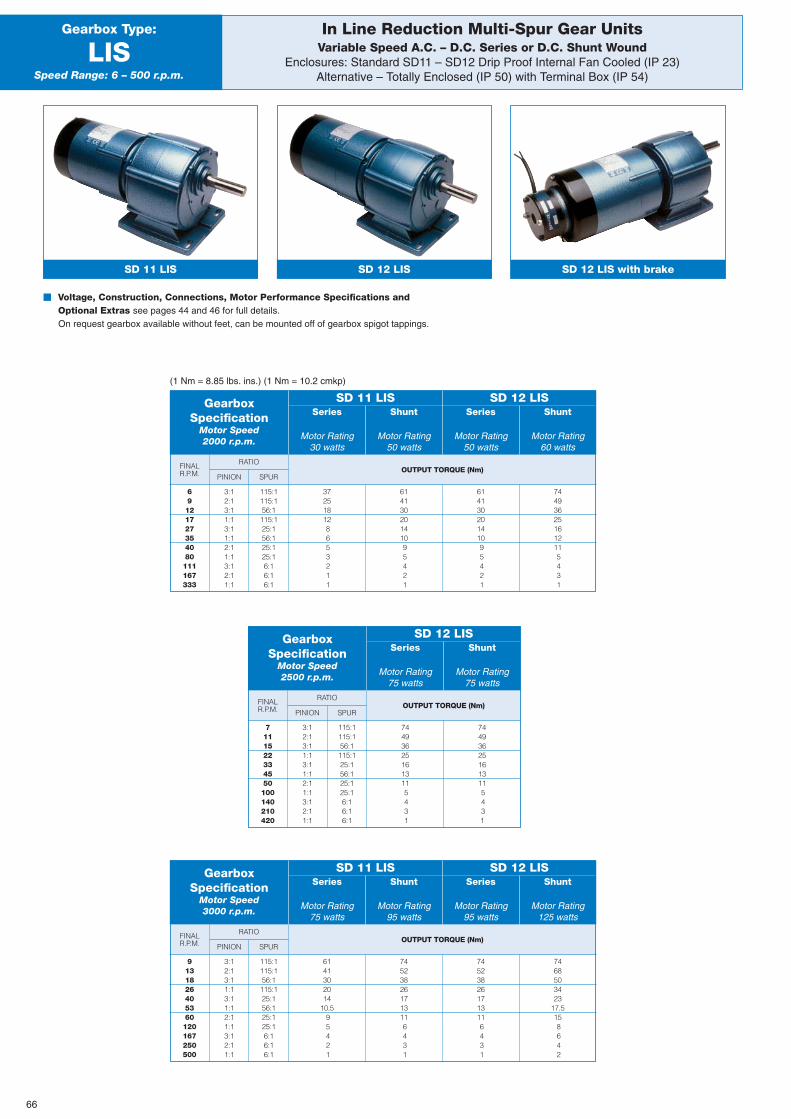
OUTPUT TORQUE (Nm)FINALR.P.M.
OUTPUT TORQUE (Nm)FINALR.P.M.
FINALR.P.M.
PINION
PINION
PINION
SPUR
SPUR
SPUR
OUTPUT TORQUE (Nm)
744936251613115431
RATIO
RATIO
RATIO
In Line Reduction Multi-Spur Gear UnitsVariable Speed A.C. – D.C. Series or D.C. Shunt Wound
Enclosures: Standard SD11 – SD12 Drip Proof Internal Fan Cooled (IP 23)Alternative – Totally Enclosed (IP 50) with Terminal Box (IP 54)
Gearbox Type:
LISSpeed Range: 6 – 500 r.p.m.
� Voltage, Construction, Connections, Motor Performance Specifications andOptional Extras see pages 44 and 46 for full details.On request gearbox available without feet, can be mounted off of gearbox spigot tappings.
(1 Nm = 8.85 lbs. ins.) (1 Nm = 10.2 cmkp)
GearboxSpecification
Motor Speed2000 r.p.m.
Series
Motor Rating30 watts
SD 11 LIS SD 12 LISShunt
Motor Rating50 watts
Series
Motor Rating50 watts
Shunt
Motor Rating60 watts
SD 12 LIS with brake
69121727354080111167333
7111522334550100140210420
9131826405360120167250500
3:12:13:11:13:11:12:11:13:12:11:1
3:12:13:11:13:11:12:11:13:12:11:1
3:12:13:11:13:11:12:11:13:12:11:1
115:1115:156:1115:125:156:125:125:16:16:16:1
115:1115:156:1115:125:156:125:125:16:16:16:1
115:1115:156:1115:125:156:125:125:16:16:16:1
372518128653211
61413020141095421
61413020141095421
744936251612115431
GearboxSpecification
Motor Speed3000 r.p.m.
Series
Motor Rating75 watts
SD 11 LIS SD 12 LISShunt
Motor Rating95 watts
Series
Motor Rating95 watts
Shunt
Motor Rating125 watts
6141302014
10.595421
745238261713116431
745238261713116431
7468503423
17.5158642
GearboxSpecification
Motor Speed2500 r.p.m.
Series
Motor Rating75 watts
SD 12 LISShunt
Motor Rating75 watts
744936251613115431
SD 12 LISSD 11 LIS
66
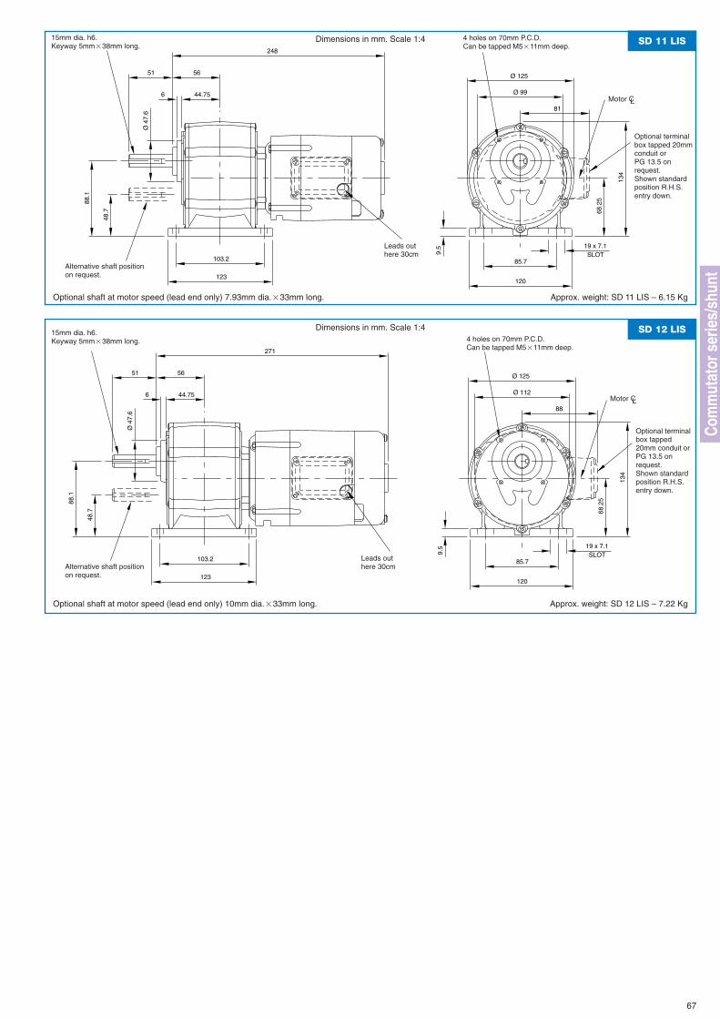
Ø 99
248
6 44.75
5651
Ø 4
7.6
Ø 125
48.7
88.1
103.2
123
134
68.2
5
9.5
SLOT19 x 7.1
120
85.7
81
SD 11 LISDimensions in mm. Scale 1:4
Optional shaft at motor speed (lead end only) 7.93mm dia.�33mm long. Approx. weight: SD 11 LIS – 6.15 Kg
Alternative shaft positionon request.
15mm dia. h6.Keyway 5mm�38mm long.
4 holes can be tappedM8�12mm deep
67
Ø 112
271
6 44.75
5651
Ø 4
7.6
Ø 125
48.7
88.1
103.2
123
134
68.2
5
9.5
SLOT19 x 7.1
120
85.7
88
SD 12 LISDimensions in mm. Scale 1:4
Optional shaft at motor speed (lead end only) 10mm dia.�33mm long. Approx. weight: SD 12 LIS – 7.22 Kg
Optional terminalbox tapped20mm conduit orPG 13.5 onrequest.Shown standardposition R.H.S.entry down.
Optional terminalbox tapped 20mmconduit orPG 13.5 onrequest.Shown standardposition R.H.S.entry down.
Motor CL
Motor CL
15mm dia. h6.Keyway 5mm�38mm long.
Alternative shaft positionon request.
4 holes on 70mm P.C.D.Can be tapped M5�11mm deep.
Leads outhere 30cm
4 holes on 70mm P.C.D.Can be tapped M5�11mm deep.
Leads outhere 30cm
Com
mut
ator
ser
ies/
shun
t
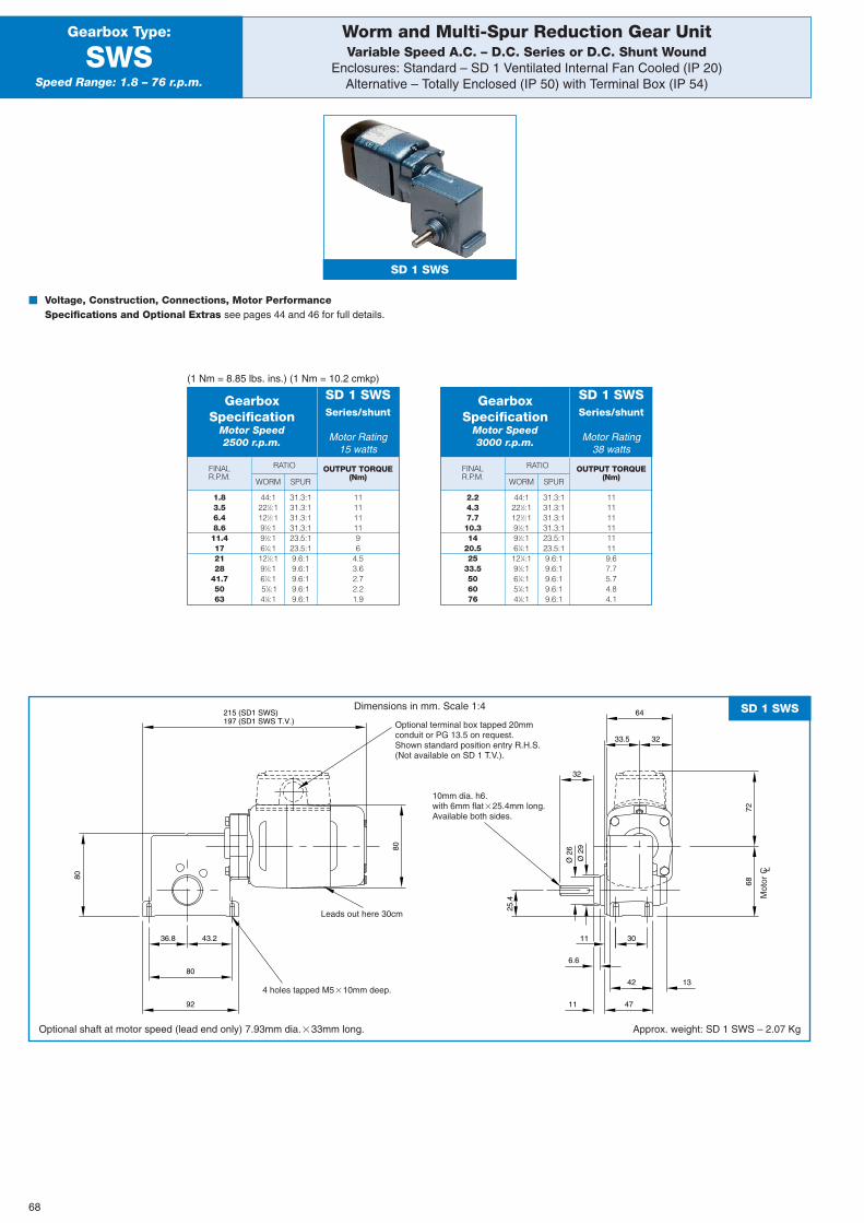
Worm and Multi-Spur Reduction Gear UnitVariable Speed A.C. – D.C. Series or D.C. Shunt Wound
Enclosures: Standard – SD 1 Ventilated Internal Fan Cooled (IP 20)Alternative – Totally Enclosed (IP 50) with Terminal Box (IP 54)
Gearbox Type:
SWSSpeed Range: 1.8 – 76 r.p.m.
SD 1 SWS
� Voltage, Construction, Connections, Motor PerformanceSpecifications and Optional Extras see pages 44 and 46 for full details.
(1 Nm = 8.85 lbs. ins.) (1 Nm = 10.2 cmkp)
68
FINALR.P.M.
OUTPUT TORQUE(Nm)WORM
RATIO
SPUR
GearboxSpecification
Motor Speed2500 r.p.m.
Series/shunt
Motor Rating15 watts
SD 1 SWS
1.83.56.48.611.4172128
41.75063
44:1221⁄2:1121⁄2:191⁄3:191⁄3:161⁄4:1121⁄2:191⁄3:161⁄4:151⁄6:141⁄8:1
31.3:131.3:131.3:131.3:123.5:123.5:19.6:19.6:19.6:19.6:19.6:1
1111111196
4.53.62.72.21.9
FINALR.P.M.
OUTPUT TORQUE(Nm)WORM
RATIO
SPUR
GearboxSpecification
Motor Speed3000 r.p.m.
Series/shunt
Motor Rating38 watts
SD 1 SWS
2.24.37.710.314
20.525
33.5506076
44:1221⁄2:1121⁄2:191⁄3:191⁄3:161⁄4:1121⁄4:191⁄3:161⁄4:151⁄6:141⁄8:1
31.3:131.3:131.3:131.3:123.5:123.5:19.6:19.6:19.6:19.6:19.6:1
1111111111119.67.75.74.84.1
80
32
64
25.4
Ø 2
9
Ø 2
6
32
33.5
6.6
1342
11 47
11 30
68
43.236.8
80
80
92
197 (SD1 SWS T.V.)215 (SD1 SWS)
72
SD 1 SWSDimensions in mm. Scale 1:4
Optional shaft at motor speed (lead end only) 7.93mm dia.�33mm long. Approx. weight: SD 1 SWS – 2.07 Kg
10mm dia. h6.with 6mm flat�25.4mm long.Available both sides.
Optional terminal box tapped 20mmconduit or PG 13.5 on request.Shown standard position entry R.H.S.(Not available on SD 1 T.V.).
4 holes tapped M5�10mm deep.
Leads out here 30cm
Mot
or C L
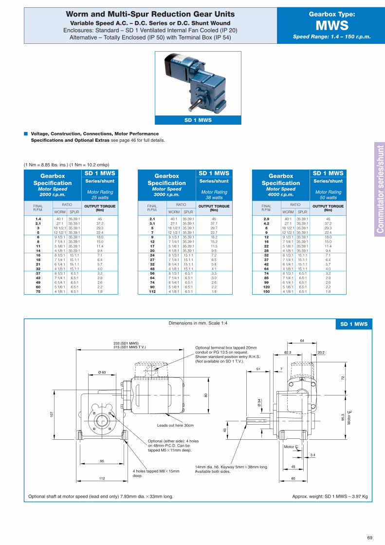
69
FINALR.P.M.
OUTPUT TORQUE(Nm)WORM
RATIO
SPUR
Worm and Multi-Spur Reduction Gear UnitsVariable Speed A.C. – D.C. Series or D.C. Shunt Wound
Enclosures: Standard – SD 1 Ventilated Internal Fan Cooled (IP 20)Alternative – Totally Enclosed (IP 50) with Terminal Box (IP 54)
Gearbox Type:
MWSSpeed Range: 1.4 – 150 r.p.m.
SD 1 MWS
GearboxSpecification
Motor Speed3000 r.p.m.
Series/shunt
Motor Rating38 watts
SD 1 MWS
2.13.15791217202427324856647490112
40:127:1
18 1/2:112 1/2:19 1/3:17 1/4:15 1/6:14 1/8:18 1/3:17 1/4:16 1/4:14 1/8:18 1/3:17 1/4:16 1/4:15 1/6:14 1/8:1
35.39:135.39:135.39:135.39:135.39:135.39:135.39:135.39:115.1:115.1:115.1:115.1:16.5:16.5:16.5:16.5:16.5:1
4537.729.722.718.215.211.59.57.26.55.84.13.33.02.62.21.8
FINALR.P.M.
OUTPUT TORQUE(Nm)WORM
RATIO
SPUR
GearboxSpecification
Motor Speed4000 r.p.m.
Series/shunt
Motor Rating50 watts
SD 1 MWS
2.94.2691216222832374264748599120150
40:127:1
18 1/2:112 1/2:19 1/3:17 1/4:15 1/6:14 1/8:18 1/3:17 1/4:16 1/4:14 1/8:18 1/3:17 1/4:16 1/4:15 1/6:14 1/8:1
35.39:135.39:135.39:135.39:135.39:135.39:135.39:135.39:115.1:115.1:115.1:115.1:16.5:16.5:16.5:16.5:16.5:1
4537.229.322.418.015.011.49.47.16.45.74.03.22.92.62.21.8
80
64233 (SD1 MWS) 215 (SD1 MWS T.V.)
751
Ø 3
4
40
95.3
20.262.3
Ø 60
95
112
3.4
60
45
107
72
SD 1 MWSDimensions in mm. Scale 1:4
Optional shaft at motor speed (lead end only) 7.93mm dia.�33mm long. Approx. weight: SD 1 MWS – 3.97 Kg
14mm dia. h6. Keyway 5mm�38mm long.Available both sides.
Optional (either side): 4 holeson 48mm P.C.D. Can betapped M5�11mm deep.
4 holes tapped M8�15mmdeep.
Leads out here 30cm
Optional terminal box tapped 20mmconduit or PG 13.5 on request.Shown standard position entry R.H.S.(Not available on SD 1 T.V.).
FINALR.P.M.
OUTPUT TORQUE(Nm)WORM
RATIO
SPUR
GearboxSpecification
Motor Speed2000 r.p.m.
Series/shunt
Motor Rating25 watts
SD 1 MWS
1.42.135681114161821323742496075
40:127:1
18 1/2:112 1/2:19 1/3:17 1/4:15 1/6:14 1/8:18 1/3:17 1/4:16 1/4:14 1/8:18 1/3:17 1/4:16 1/4:15 1/6:14 1/8:1
35.39:135.39:135.39:135.39:135.39:135.39:135.39:135.39:115.1:115.1:115.1:115.1:16.5:16.5:16.5:16.5:16.5:1
4537.229.322.418.015.011.49.47.16.45.74.03.22.92.62.21.8
� Voltage, Construction, Connections, Motor PerformanceSpecifications and Optional Extras see page 46 for full details.
(1 Nm = 8.85 lbs. ins.) (1 Nm = 10.2 cmkp)
Com
mut
ator
ser
ies/
shun
t
Motor CL
Mot
or C L
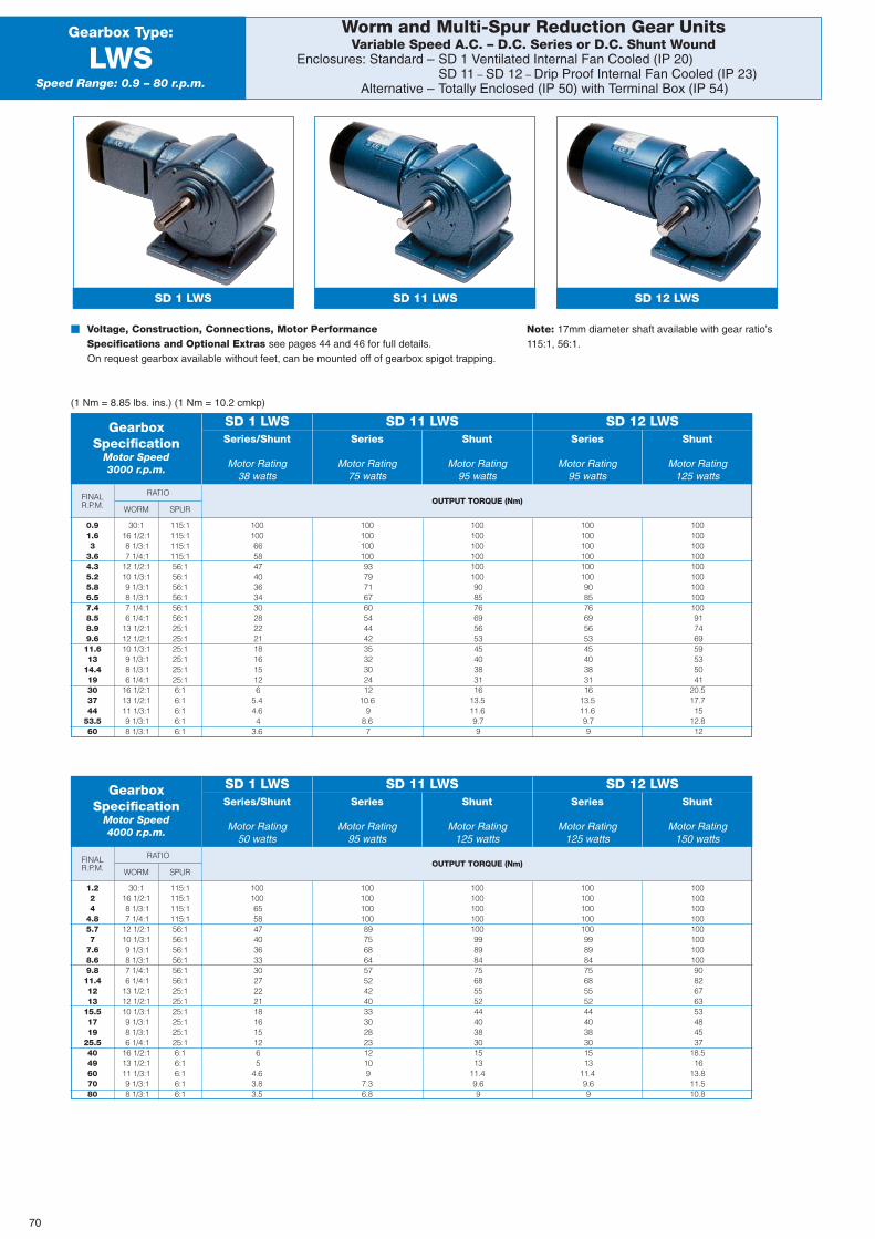
OUTPUT TORQUE (Nm)FINALR.P.M.
Shunt
Motor Rating95 watts
Series
Motor Rating95 watts
RATIO
WORM SPUR
Worm and Multi-Spur Reduction Gear UnitsVariable Speed A.C. – D.C. Series or D.C. Shunt Wound
Enclosures: Standard – SD 1 Ventilated Internal Fan Cooled (IP 20)SD 11 – SD 12 – Drip Proof Internal Fan Cooled (IP 23)
Alternative – Totally Enclosed (IP 50) with Terminal Box (IP 54)
Gearbox Type:
LWSSpeed Range: 0.9 – 80 r.p.m.
� Voltage, Construction, Connections, Motor PerformanceSpecifications and Optional Extras see pages 44 and 46 for full details.On request gearbox available without feet, can be mounted off of gearbox spigot trapping.
(1 Nm = 8.85 lbs. ins.) (1 Nm = 10.2 cmkp)
GearboxSpecification
Motor Speed3000 r.p.m.
Series/Shunt
Motor Rating38 watts
SD 1 LWSSeries
Motor Rating75 watts
SD 11 LWS SD 12 LWSShunt
Motor Rating125 watts
0.91.63
3.64.35.25.86.57.48.58.99.611.613
14.419303744
53.560
30:116 1/2:18 1/3:17 1/4:1
12 1/2:110 1/3:19 1/3:18 1/3:17 1/4:16 1/4:1
13 1/2:112 1/2:110 1/3:19 1/3:18 1/3:16 1/4:1
16 1/2:113 1/2:111 1/3:19 1/3:18 1/3:1
115:1115:1115:1115:156:156:156:156:156:156:125:125:125:125:125:125:16:16:16:16:16:1
10010066584740363430282221181615126
5.44.64
3.6
10010010010093797167605444423532302412
10.69
8.67
1001001001001001009085766956534540383116
13.511.69.79
1001001001001001009085766956534540383116
13.511.69.79
10010010010010010010010010091746959535041
20.517.715
12.812
OUTPUT TORQUE (Nm)FINALR.P.M.
RATIO
WORM SPUR
1.224
4.85.77
7.68.69.811.41213
15.51719
25.54049607080
30:116 1/2:18 1/3:17 1/4:1
12 1/2:110 1/3:19 1/3:18 1/3:17 1/4:16 1/4:1
13 1/2:112 1/2:110 1/3:19 1/3:18 1/3:16 1/4:1
16 1/2:113 1/2:111 1/3:19 1/3:18 1/3:1
115:1115:1115:1115:156:156:156:156:156:156:125:125:125:125:125:125:16:16:16:16:16:1
100100655847403633302722211816151265
4.63.83.5
10010010010089756864575242403330282312109
7.36.8
10010010010010099898475685552444038301513
11.49.69
10010010010010099898475685552444038301513
11.49.69
1001001001001001001001009082676353484537
18.516
13.811.510.8
Shunt
Motor Rating125 watts
Series
Motor Rating125 watts
GearboxSpecification
Motor Speed4000 r.p.m.
Series/Shunt
Motor Rating50 watts
SD 1 LWSSeries
Motor Rating95 watts
SD 11 LWS SD 12 LWSShunt
Motor Rating150 watts
SD 11 LWSSD 1 LWS SD 12 LWS
70
Note: 17mm diameter shaft available with gear ratio’s115:1, 56:1.
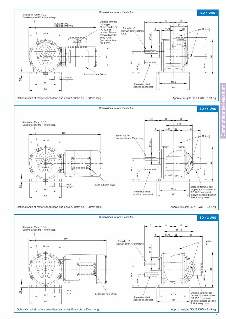
80
252 (SD1 LWS)234 (SD1 LWS T.V.)
64
565651
226 44.75
Ø 4
7.6Ø 125
123
103.2
19 x 7.1SLOT
85.7
120
9.5
68.2
5
134
88.1
48.4
72
SD 1 LWSDimensions in mm. Scale 1:4
Optional shaft at motor speed (lead end only) 7.93mm dia.�33mm long. Approx. weight: SD 1 LWS – 5.13 Kg
4 holes on 70mm P.C.D.Can be tapped M5�11mm deep.
Alternative shaftposition on request.
71
Optional terminalbox tapped20mm conduit orPG 13.5 onrequest. Shownstandard positionentry R.H.S.(Not available onSD 1 T.V.).
Ø 99
269
565651
226 44.75
Ø 4
7.6Ø 125
123
103.2
19 x 7.1SLOT
85.7
120
9.5
68.2
5
134
88.1
48.4
81
SD 11 LWSDimensions in mm. Scale 1:4
Optional shaft at motor speed (lead end only) 7.93mm dia.�33mm long. Approx. weight: SD 11 LWS – 6.41 Kg
Ø 112
291
565651
226 44.75
Ø 4
7.6Ø 125
123
103.2
19 x 7.1
SLOT85.7
120
9.5
68.2
5
134
88.1
48.4
88
SD 12 LWSDimensions in mm. Scale 1:4
Optional shaft at motor speed (lead end only) 10mm dia.�33mm long. Approx. weight: SD 12 LWS – 7.48 Kg
15mm dia. h6.Keyway 5mm�38mmlong.
Motor CL
Motor CL
MotorCL
15mm dia. h6.Keyway 5mm�38mm long.
Leads out here 30cmOptional terminal boxtapped 20mm conduit orPG 13.5 on request.Shown standard positionR.H.S. entry down.
4 holes on 70mm P.C.D.Can be tapped M5�11mm deep.
Leads out here 30cm
Alternative shaftposition on request.
15mm dia. h6.Keyway 5mm�38mm long.
Leads out here 30cm Optional terminal boxtapped 20mm conduit orPG 13.5 on request.Shown standard positionR.H.S. entry down.
4 holes on 70mm P.C.D.Can be tapped M5�11mm deep.
Alternative shaftposition on request.
Com
mut
ator
ser
ies/
shun
t
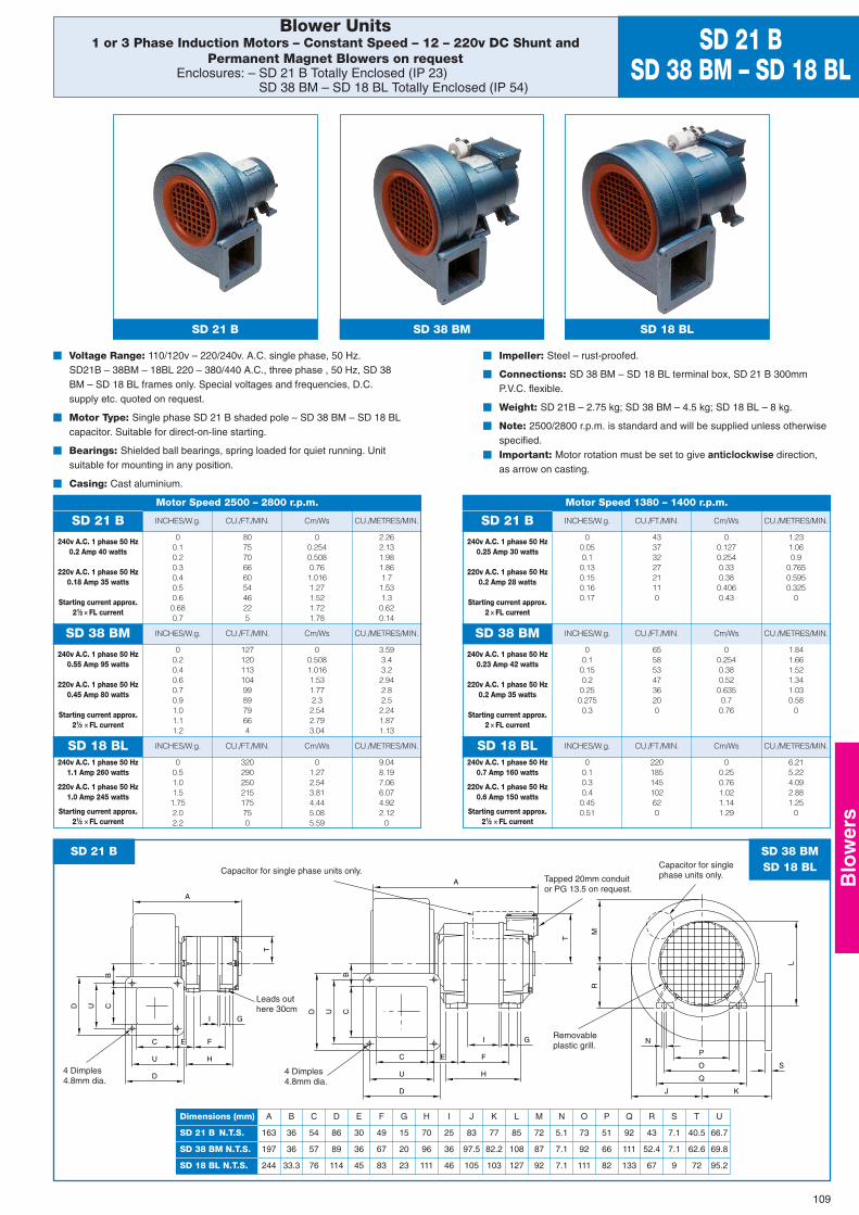
N
RM
L
S
P
O
Q
J K
T
GI
H
FE
B
D U C
D
U
C
A
B
D U C
T
G
E
I
F
H
D
U
C
A
A
163
197
244
B
36
36
33.3
C
54
57
76
D
86
89
114
E
30
36
45
F
49
67
83
G
15
20
23
H
70
96
111
I
25
36
46
J
83
97.5
105
K
77
82.2
103
L
85
108
127
M
72
87
92
N
5.1
7.1
7.1
O
73
92
111
P
51
66
82
Q
92
111
133
R
43
52.4
67
S
7.1
7.1
9
T
40.5
62.6
72
U
66.7
69.8
95.2
Dimensions (mm)
SD 21 B N.T.S.
SD 38 BM N.T.S.
SD 18 BL N.T.S.
SD 38 BMSD 18 BL
Leads outhere 30cm
Tapped 20mm conduitor PG 13.5 on request.
Capacitor for singlephase units only.
Removableplastic grill.
Capacitor for single phase units only.
4 Dimples4.8mm dia.
4 Dimples4.8mm dia.
SD 21 B
CU./METRES/MIN. CU./METRES/MIN.
CU./METRES/MIN. CU./METRES/MIN.
CU./METRES/MIN. CU./METRES/MIN.
Blower Units1 or 3 Phase Induction Motors – Constant Speed – 12 – 220v DC Shunt and
Permanent Magnet Blowers on requestEnclosures: – SD 21 B Totally Enclosed (IP 23)
SD 38 BM – SD 18 BL Totally Enclosed (IP 54)
SD 21 BSD 38 BM – SD 18 BL
� Voltage Range: 110/120v – 220/240v. A.C. single phase, 50 Hz.SD21B – 38BM – 18BL 220 – 380/440 A.C., three phase , 50 Hz, SD 38BM – SD 18 BL frames only. Special voltages and frequencies, D.C.supply etc. quoted on request.
� Motor Type: Single phase SD 21 B shaded pole – SD 38 BM – SD 18 BLcapacitor. Suitable for direct-on-line starting.
� Bearings: Shielded ball bearings, spring loaded for quiet running. Unitsuitable for mounting in any position.
� Casing: Cast aluminium.
� Impeller: Steel – rust-proofed.
� Connections: SD 38 BM – SD 18 BL terminal box, SD 21 B 300mmP.V.C. flexible.
� Weight: SD 21B – 2.75 kg; SD 38 BM – 4.5 kg; SD 18 BL – 8 kg.
� Note: 2500/2800 r.p.m. is standard and will be supplied unless otherwisespecified.
� Important: Motor rotation must be set to give anticlockwise direction,as arrow on casting.
SD 21 B SD 21 B
SD 38 BM SD 38 BM
SD 18 BL SD 18 BL
INCHES/W.g. INCHES/W.g.
INCHES/W.g. INCHES/W.g.
INCHES/W.g. INCHES/W.g.
CU./FT./MIN. CU./FT./MIN.
CU./FT./MIN. CU./FT./MIN.
CU./FT./MIN. CU./FT./MIN.
Cm/Ws Cm/Ws
Cm/Ws Cm/Ws
Cm/Ws Cm/Ws
Motor Speed 2500 – 2800 r.p.m. Motor Speed 1380 – 1400 r.p.m.
240v A.C. 1 phase 50 Hz0.2 Amp 40 watts
220v A.C. 1 phase 50 Hz0.18 Amp 35 watts
Starting current approx.21⁄2 × FL current
240v A.C. 1 phase 50 Hz0.25 Amp 30 watts
220v A.C. 1 phase 50 Hz0.2 Amp 28 watts
Starting current approx.2 × FL current
00.10.20.30.40.50.60.680.7
80757066605446225
00.2540.5080.761.0161.271.521.721.78
2.262.131.981.861.71.531.30.620.14
240v A.C. 1 phase 50 Hz0.55 Amp 95 watts
220v A.C. 1 phase 50 Hz0.45 Amp 80 watts
Starting current approx.21⁄2 × FL current
240v A.C. 1 phase 50 Hz0.23 Amp 42 watts
220v A.C. 1 phase 50 Hz0.2 Amp 35 watts
Starting current approx.2 × FL current
00.20.40.60.70.91.01.11.2
127120113104998979664
00.5081.0161.531.772.32.542.793.04
3.593.43.22.942.82.52.241.871.13
240v A.C. 1 phase 50 Hz1.1 Amp 260 watts
220v A.C. 1 phase 50 Hz1.0 Amp 245 watts
Starting current approx.21⁄2 × FL current
240v A.C. 1 phase 50 Hz0.7 Amp 160 watts
220v A.C. 1 phase 50 Hz0.6 Amp 150 watts
Starting current approx.21⁄2 × FL current
00.51.01.51.752.02.2
320290250215175750
01.272.543.814.445.085.59
9.048.197.066.074.922.12
0
00.050.10.130.150.160.17
4337322721110
00.1270.2540.330.380.4060.43
1.231.060.9
0.7650.5950.325
0
00.10.150.20.250.2750.3
6558534736200
00.2540.380.520.6350.70.76
1.841.661.521.341.030.58
0
00.10.30.40.450.51
220185145102620
00.250.761.021.141.29
6.215.224.092.881.25
0
SD 38 BM SD 18 BLSD 21 B
109
Blo
wer
s
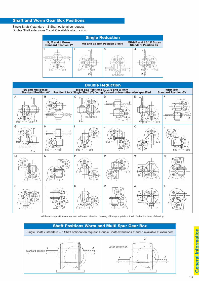
Double Reduction
Single Reduction
113
Shaft and Worm Gear Box Positions
Shaft Positions Worm and Multi Spur Gear Box
Single Shaft Y standard – Z Shaft optional on request.Double Shaft extensions Y and Z available at extra cost.
Single Shaft Y standard – Z Shaft optional on request. Double Shaft extensions Y and Z available at extra cost
S, M and L Boxes MB and LB Box Position 3 only MB/MF and LB/LF BoxesStandard Position 1Y Standard Position 3Y
SS and MM Boxes MBM Box Positions C, G, S and W only. MBM BoxStandard Position AY Position I to X Single Shaft (Y) facing forward unless otherwise specified Standard Position GY
All the above positions correspond to the end elevation drawing of the appropriate unit with feet at the base of drawing.
Standard position1Y.
XWVUTS
RQPONM
LKJIHG
FEDCB
ZY
Z
Y
ZYZY
Z
Y
ZY
Z
Y
Z
Y
A
1 2 3 4
ZY
Z
Y
Z
Y
ZY
1 2
Lower position 2Y.
ZY
ZY
Gen
eral
Info
rmat
ion
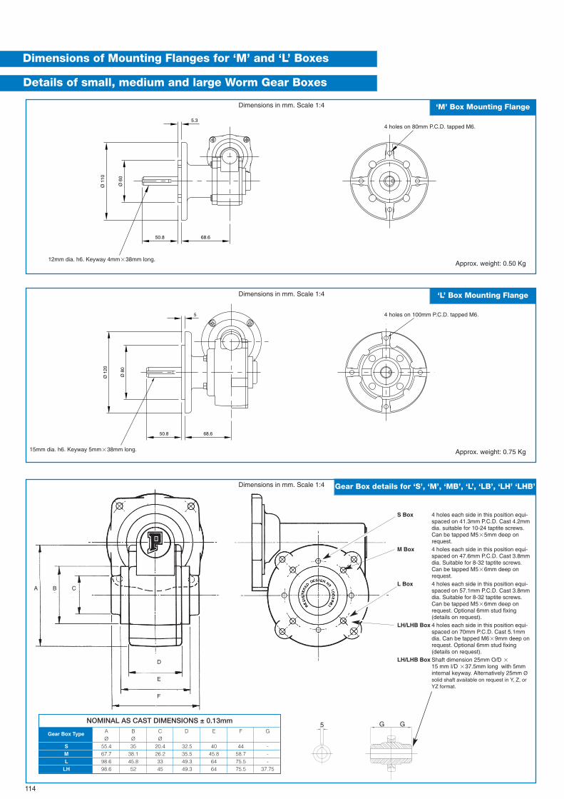
Ø 1
10
Ø 6
05.3
50.8 68.6
NOMINAL AS CAST DIMENSIONS ± 0.13mmA B C D E F GReducteur typeØ Ø Ø
S 55.4 35 20.4 32.5 40 44 -M 67.7 38.1 26.2 35.5 45.8 58.7 -L 98.6 45.8 33 49.3 64 75.5 -
LH 98.6 52 45 49.3 64 75.5 37.75
114
Dimensions of Mounting Flanges for ‘M’ and ‘L’ Boxes
Details of small, medium and large Worm Gear Boxes
Ø 1
20
Ø 8
0
5
50.8 68.6
12mm dia. h6. Keyway 4mm�38mm long.
15mm dia. h6. Keyway 5mm�38mm long.
4 holes on 80mm P.C.D. tapped M6.
4 holes on 100mm P.C.D. tapped M6.
A B C
D
E
F
5
Approx. weight: 0.50 Kg
Approx. weight: 0.75 Kg
G G
S Box 4 holes each side in this position equi-spaced on 41.3mm P.C.D. Cast 4.2mmdia. suitable for 10-24 taptite screws.Can be tapped M5�5mm deep onrequest.
M Box 4 holes each side in this position equi-spaced on 47.6mm P.C.D. Cast 3.8mmdia. Suitable for 8-32 taptite screws.Can be tapped M5�6mm deep onrequest.
L Box 4 holes each side in this position equi-spaced on 57.1mm P.C.D. Cast 3.8mmdia. Suitable for 8-32 taptite screws.Can be tapped M5�6mm deep onrequest. Optional 6mm stud fixing(details on request).
LH/LHB Box 4 holes each side in this position equi-spaced on 70mm P.C.D. Cast 5.1mmdia. Can be tapped M6�9mm deep onrequest. Optional 6mm stud fixing(details on request).
LH/LHB Box Shaft dimension 25mm O/D �15 mm I/D �37.5mm long with 5mminternal keyway. Alternatively 25mm Øsolid shaft available on request in Y, Z, orYZ format.
Gear Box Type
SML
LH
‘M’ Box Mounting Flange
‘L’ Box Mounting Flange
Gear Box details for ‘S’, ‘M’, ‘MB’, ‘L’, ‘LB’, ‘LH’ ‘LHB’
Dimensions in mm. Scale 1:4
Dimensions in mm. Scale 1:4
Dimensions in mm. Scale 1:4
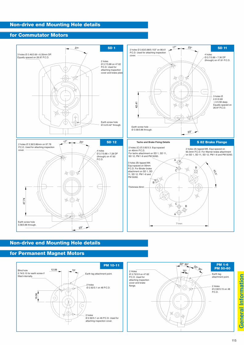
115
Non-drive end Mounting Hole details
for Commutator Motors
23°
23°17°
42.4
1
27°
C
A
B
B
BC
A
43.5°
47.7
4
23°
23°17°
15°
22° 30"
22° 30"
19.5
6
19°12.06
Non-drive end Mounting Hole details
for Permanent Magnet Motors
2 holesØ 3.7/3.88 on 47.62P.C.D. Used forattaching inspectioncover and brake plate.
Earth screw holeØ 3.2/3.42" through.
3 holes Ø 2.46/2.69�6.35mm DP.Equally spaced on 26.97 P.C.D.
2 holes Ø 3.36/3.86mm on 97.78P.C.D. Used for attaching inspectioncover.
Earth screw hole3.58/3.86 through.
Earth tag attachment point. Earth tagattachment point.
2 HolesØ 2.92/3.15 on 48P.C.D.
2 HolesØ 3.73/3.9 on 47.62P.C.D. Used forattaching inspectioncover and brakeflange.2 holes
Ø 2.92/3.1 on 48 P.C.D.
2 holesØ 2.92/3.1 on 46 P.C.D. Used forattaching inspection cover.
Blind hole2.74/3.15 for earth screw iffitted internally.
4 holesØ 3.7/3.88�7.28 DP(through) on 47.62P.C.D.
2 holes (A) tapped M5. Equi-spaced on60.3mm P.C.D. For Warner brake attachmenton SD 1, SD 11, SD 12, PM 1-6 and PM 50/60.
3 holes (B) tapped M4.Equi-spaced on 56mmP.C.D. For Binder brakeattachment on SD 1, SD11, SD 12. PM 1-6 andPM 50/60.
Thickness 8mm
71mm
2 holes (C) Ø 2.92/3.3. Equi-spacedon 46mm P.C.D.For tacho attachment on SD 1, SD 11,SD 12, PM 1-6 and PM 50/60.
2 holes Ø 3.63/3.88/0.153” on 86.61P.C.D. Used for attaching inspectioncover.
Earth screw holeØ 3.58/3.86 through.
4 holesØ.3.7/3.88�7.36 DP(through) on 47.61 P.C.D.
3 holes Ø2.51/2.69�0.5.58 deep.Equally spaced on26.97 P.C.D.
Tacho and Brake Fixing Details
SD 1 SD 11
SD 12 S 82 Brake Flange
PM 10-11 PM 1-6PM 50-60
Gen
eral
Info
rmat
ion
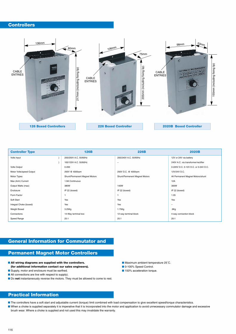
116
Controllers
General Information for Commutator and
Permanent Magnet Motor Controllers
Practical Information
126 Boxed Controllers 226 Boxed Controller 2020B Boxed Controller
Controller Type 126B 226B 2020B
Volts Input } 200/250V A.C. 50/60Hz 200/240V A.C. 50/60Hz 12V or 24V via battery
} 100/120V A.C. 50/60Hz – 240V A.C. via transformer/rectifier
Volts Output 0-200 0-220V D.C. 0-12V D.C. or 0-24V D.C.
Motor Volts/speed Output 200V @ 4000rpm 200V D.C. @ 4000rpm 12V/24V D.C.
Motor Types Shunt/Permanent Magnet Motors Shunt/Permenent Magnet Motors All Permanent Magnet Motors/shunt
Max (Arm) Current 1.9A Continuous 12A
Output Watts (max) 380W 140W 300W
Enclosure IP 22 (boxed) IP 22 (boxed) IP 22 (boxed)
Form Factor 1 1 1.05
Soft Start Yes Yes Yes
Integral Choke (boxed) Yes Yes –
Weight Boxed 3.25Kg 1.75Kg .9Kg
Connections 14-Way terminal box 12-way terminal block 4-way connection block
Speed Range 25:1 25:1 20:1
■ All wiring diagrams are supplied with the controllers.(for additional information contact our sales engineers).
■ Supply, motor and enclosure must be earthed.■ All connections are live with respect to supply).■ Do not instantaneously reverse the motors. They must be allowed to come to rest.
■ Maximum ambient temperature 25˚C.■ 0-100% Speed Control.■ 150% acceleration torque.
■ The controllers have a soft start and adjustable current (torque) limit combined with load compensation to give excellent speed/torque characteristics.■ When a choke is supplied separately it is imperative that it is incorporated into the motor and application to avoid unnecessary commutator damage and excessive
brush wear. Where a choke is supplied and not used this may invalidate the warranty.
136mm
80mm
217m
m (
incl
udin
g fix
ing
lip)
106mm
75mm
205m
m (
incl
udin
g fix
ing
lip)
CABLEENTRIES
CABLEENTRIES
CABLEENTRIES
98mm 53mm
155m
m (
incl
udin
g fix
ing
lip)
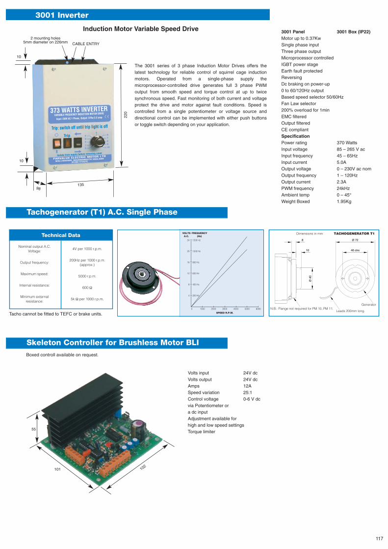
Technical Data
Tachogenerator (T1) A.C. Single Phase
Skeleton Controller for Brushless Motor BLI
10
8
Ø 4
0
Ø 72
46 ctrs
N.B.: Flange not required for PM 10, PM 11.Leads 200mm long.
Generator
Dimensions in mm TACHOGENERATOR T1
Nominal output A.C.Voltage:
Output frequency:
Maximum speed:
Internal resistance:
Minimum externalresistance:
4V per 1000 r.p.m.
200Hz per 1000 r.p.m.(approx.)
5000 r.p.m.
600
5k per 1000 r.p.m.
0 1000 2000 3000 4000 5000 6000
SPEED R.P.M.
VOLTS FREQUENCYA.C. (Hz)
24 1200 Hz
20 1000 Hz
16 800 Hz
12 600 Hz
8 400 Hz
4 200 Hz
Tacho cannot be fitted to TEFC or brake units.
3001 Inverter
The 3001 series of 3 phase Induction Motor Drives offers thelatest technology for reliable control of squirrel cage inductionmotors. Operated from a single-phase supply themicroprocessor-controlled drive generates full 3 phase PWMoutput from smooth speed and torque control at up to twicesynchronous speed. Fast monitoring of both current and voltageprotect the drive and motor against fault conditions. Speed iscontrolled from a single potentiometer or voltage source anddirectional control can be implemented with either push buttonsor toggle switch depending on your application.
Boxed controll available on request.
220
10
55
101 102
98
10
2 mounting holes5mm diameter on 226mm CABLE ENTRY
135
373 WATTS INVERTERVARIABLE FREQUENCY INDUCTION MOTOR DRIVE
Input: 230V AC 1 Phase, Output: 375w 3.5 amp
Trip: switch off until trip light is off
Trip
Isolate from supply before removing cover
PARVALUX ELECTRIC MOTOR LTD
WALLISDOWN, BOURNEMOUTH ENGLAND
01202 512575
3001 Panel 3001 Box (IP22)Motor up to 0.37KwSingle phase inputThree phase outputMicroprocessor controlledIGBT power stageEarth fault protectedReversingDc braking on power-up0 to 60/120Hz outputBased speed selector 50/60HzFan Law selector200% overload for 1minEMC filteredOutput filteredCE compliantSpecificationPower rating 370 WattsInput voltage 85 – 265 V acInput frequency 45 – 65HzInput current 5.0AOutput voltage 0 – 230V ac nomOutput frequency 1 – 120HzOutput current 2.3APWM frequency 24kHzAmbient temp 0 – 45°Weight Boxed 1.95Kg
Volts input 24V dcVolts output 24V dcAmps 12ASpeed variation 25:1Control voltage 0-6 V dcvia Potentiometer ora dc inputAdjustment available forhigh and low speed settingsTorque limiter
Induction Motor Variable Speed Drive
117
Parvalux International HQ 490 Wallisdown RoadBournemouth BH11 8PUUnited Kingdom T :: +44 120 251 2575 F :: +44 120 253 0885 E :: [email protected]
Parvalux New York 18 Blooms Corners RoadWarwick 10990United States T :: +1 845 258 7482 F :: +1 845 986 2130 E :: [email protected]
Parvalux Paris 4 rue Guynemer78280 GuyancourtFrance T :: +33 130 437 273 F :: +33 130 441 063 E :: [email protected]
Parvalux Frankfurt Egertshammer 1D-61276 AltweilnauGermany T :: +49 6083 958 870 F :: +49 6083 958 872 E :: [email protected]
Parvalux Warsaw al. Niepodleglosci 18600-608 WarszawaPoland T :: +48 22 629 7348 F :: +48 22 244 2481 E :: [email protected]
Parvalux Johannesburg 132 Leicester RoadJohannesburg 2094South Africa T :: +27 11 622 6826F :: +27 11 622 6823 E :: [email protected]
Parvalux Service Centre Unit 4, 26 Avenue Road Birmingham B6 4DYUnited Kingdom T :: +44 121 552 6581 F :: +44 121 523 0449 E :: [email protected]
www.parvalux.com
Worldwide approved distributor network
AustraliaEastland Electric Motors +61 3 9879 1798 www.au.parvalux.com
Austria & Czech Rep.Kwapil & Co +43 1278 8585 www.kwapil.com
ChinaEuro-Me +86 755 8384 2750 www.euro-me.com
ColombiaInpraindsa +57 4393 5238 www.inpraindsa.com
DenmarkParlock +45 4390 6100 www.parlock.dk
HungaryQ-Tech Engineering +36 1405 3338 www.q-tech.hu
IrelandRotate Ltd +353 1 830 5455 www.rotate.ie
IndiaMelkev Machinery +91 22 2500 8154 www.melkev.com
ItalyLog-Italia +39 3 3154 2800 www.log-italia.it
SpainErmec +34 9 3450 1600 www.ermec.com
SwedenSDT +46 4238 0800 www.sdt.se
SwitzerlandElectro-Müller +41 3 2344 1010 www.electro-mueller.ch
United KingdomRS Components +44 1536 201234 www.rswww.com