renault twingo · renault twingo vehicle user manual. a passion for performance elf, partner of...
TRANSCRIPT

Renault TWINGO Vehicle user manual

A passion for performance
ELF, partner of
RENAULT recommends ELFPartners in cutting-edge automotive technology, Elf and Renault combine their expertise on both the racetrack and the city streets. This enduring partnership gives drivers a range of lubricants perfectly suited to Renault cars. Lasting protection and optimum performance for your engine – guaranteed. Whether changing the oil or simply topping up, to find the approved ELF lubricant best suited to your vehicle, ask your Renault dealer for a recommendation or consult your vehi-cle maintenance handbook.
www.lubricants.elf.com
A brand from
2016-Elf-ENG.indd 1 18/05/2016 14:20

0.1
Translated from French. Copying or translation, in part or in full, is forbidden unless prior written permission has been obtained from the car manufacturer.
Welcome to your new vehicle
The descriptions of the models given in this handbook are based on the technical specifications at the time of writing. This hand-book covers all items of equipment (both standard and optional) available for these models but whether or not these are fitted to the vehicle depends on the version, options selected and the country where the vehicle is sold.This handbook may also contain information about items of equipment to be introduced later in the model year.
Enjoy driving your new vehicle.
This driver’s handbook contains the information necessary:– for you to familiarise yourself with your vehicle, to use it to its best advantage and to benefit fully from the all the functions and
the technical developments it incorporates.– to ensure that it always gives the best performance by following the simple, but comprehensive advice concerning regular main-
tenance.– to enable you to deal quickly with minor faults not requiring specialist attention.It is well worth taking a few minutes to read this handbook to familiarise yourself with the information and guidelines it contains about the vehicle and its functions and new features. If certain points are still unclear, our Network technicians will be only too pleased to provide you with any additional information.To help you, you will find the following symbols:
and These appear in the vehicle and indicate that you should consult the manual for detailed information and/or limits on operations with respect to your vehicle’s equipment.
anywhere in the manual indicates a hazard, danger or a safety recommendation.

0.2

0.3
Getting to know your vehicle ...............................
Driving ...................................................................
Your comfort .........................................................
Maintenance .........................................................
Practical advice ....................................................
Technical specifications ......................................
Alphabetical index ...............................................
Sections
1
C O N T E N T S
2
3
4
5
6
7

0.4

1.1
Section 1: Getting to know your vehicle
Key/radio frequency remote controls: general information, use, deadlocking . . . . . . . . . . . . . . . . . . 1.2Opening and closing the doors . . . . . . . . . . . . . . . . . . . . . . . . . . . . . . . . . . . . . . . . . . . . . . . . . . . . . 1.6Locking, unlocking the opening elements . . . . . . . . . . . . . . . . . . . . . . . . . . . . . . . . . . . . . . . . . . . . . 1.8Automatic locking when driving . . . . . . . . . . . . . . . . . . . . . . . . . . . . . . . . . . . . . . . . . . . . . . . . . . . . . 1.10Front seats. . . . . . . . . . . . . . . . . . . . . . . . . . . . . . . . . . . . . . . . . . . . . . . . . . . . . . . . . . . . . . . . . . . . . 1.11Seat belts. . . . . . . . . . . . . . . . . . . . . . . . . . . . . . . . . . . . . . . . . . . . . . . . . . . . . . . . . . . . . . . . . . . . . . 1.12Additional methods of restraint . . . . . . . . . . . . . . . . . . . . . . . . . . . . . . . . . . . . . . . . . . . . . . . . . . . . . 1.15
in addition to the front seat belts . . . . . . . . . . . . . . . . . . . . . . . . . . . . . . . . . . . . . . . . . . . . . . 1.15to the rear seat belts . . . . . . . . . . . . . . . . . . . . . . . . . . . . . . . . . . . . . . . . . . . . . . . . . . . . . . . 1.19side . . . . . . . . . . . . . . . . . . . . . . . . . . . . . . . . . . . . . . . . . . . . . . . . . . . . . . . . . . . . . . . . . . . . . 1.20
Steering wheel/Power-assisted steering . . . . . . . . . . . . . . . . . . . . . . . . . . . . . . . . . . . . . . . . . . . . . . 1.22Child safety: General information . . . . . . . . . . . . . . . . . . . . . . . . . . . . . . . . . . . . . . . . . . . . . . . . . . . 1.23
choosing a child seat mounting . . . . . . . . . . . . . . . . . . . . . . . . . . . . . . . . . . . . . . . . . . . . . . . 1.26fitting a child seat, general information . . . . . . . . . . . . . . . . . . . . . . . . . . . . . . . . . . . . . . . . . . 1.29
Child safety: attachment by seat belt or by Isofix system . . . . . . . . . . . . . . . . . . . . . . . . . . . . . . . . . 1.31Deactivating/activating the front passenger airbag . . . . . . . . . . . . . . . . . . . . . . . . . . . . . . . . 1.36
Rear view mirrors . . . . . . . . . . . . . . . . . . . . . . . . . . . . . . . . . . . . . . . . . . . . . . . . . . . . . . . . . . . . . . . 1.39Driving position . . . . . . . . . . . . . . . . . . . . . . . . . . . . . . . . . . . . . . . . . . . . . . . . . . . . . . . . . . . . . . . . . 1.40Instrument panel, on-board computer . . . . . . . . . . . . . . . . . . . . . . . . . . . . . . . . . . . . . . . . . . . . . . . . 1.44Clock and outdoor temperature . . . . . . . . . . . . . . . . . . . . . . . . . . . . . . . . . . . . . . . . . . . . . . . . . . . . . 1.56Exterior lighting and signals. . . . . . . . . . . . . . . . . . . . . . . . . . . . . . . . . . . . . . . . . . . . . . . . . . . . . . . . 1.58Audible and visual signals . . . . . . . . . . . . . . . . . . . . . . . . . . . . . . . . . . . . . . . . . . . . . . . . . . . . . . . . . 1.61Headlight beam adjustment . . . . . . . . . . . . . . . . . . . . . . . . . . . . . . . . . . . . . . . . . . . . . . . . . . . . . . . . 1.62Washers, wipers . . . . . . . . . . . . . . . . . . . . . . . . . . . . . . . . . . . . . . . . . . . . . . . . . . . . . . . . . . . . . . . . 1.64Fuel tank (filling with fuel) . . . . . . . . . . . . . . . . . . . . . . . . . . . . . . . . . . . . . . . . . . . . . . . . . . . . . . . . . 1.68

1.2
Radio frequency remote control unit A or B1 Locks all the opening elements.2 Unlocks all the opening elements.3 Ignition key, front left door and fuel
filler cap.4 Opens the tailgate only.
KEY, RADIO FREQUENCY REMOTE CONTROL: general information (1/2)
A
AdviceAvoid leaving the remote control in hot, cold or humid areas.
B
5
1
2
3
4
3
2
4
1
3C
Key CRemote control with switchblade key5 Locks/Unlocks the key insert for
remote control B. To release the insert from its housing, press button 5, it comes out automatically. Press button 5 and guide the insert back into its housing.
1.3
KEY, RADIO FREQUENCY REMOTE CONTROL: general information (2/2)
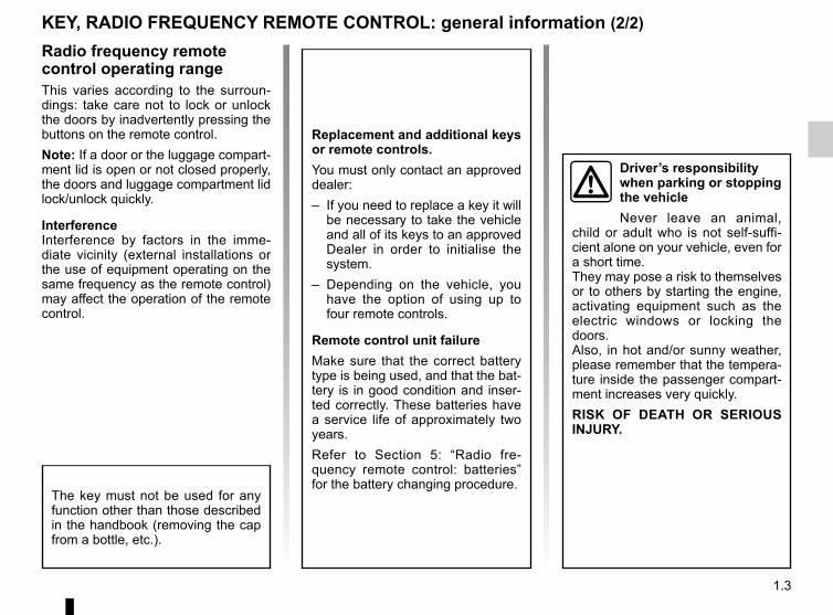
Radio frequency remote control operating rangeThis varies according to the surroun-dings: take care not to lock or unlock the doors by inadvertently pressing the buttons on the remote control.Note: If a door or the luggage compart-ment lid is open or not closed properly, the doors and luggage compartment lid lock/unlock quickly.
InterferenceInterference by factors in the imme-diate vicinity (external installations or the use of equipment operating on the same frequency as the remote control) may affect the operation of the remote control.
Replacement and additional keys or remote controls.You must only contact an approved dealer:– If you need to replace a key it will
be necessary to take the vehicle and all of its keys to an approved Dealer in order to initialise the system.
– Depending on the vehicle, you have the option of using up to four remote controls.
Remote control unit failureMake sure that the correct battery type is being used, and that the bat-tery is in good condition and inser-ted correctly. These batteries have a service life of approximately two years.Refer to Section 5: “Radio fre-quency remote control: batteries” for the battery changing procedure.
The key must not be used for any function other than those described in the handbook (removing the cap from a bottle, etc.).
Driver’s responsibility when parking or stopping the vehicleNever leave an animal,
child or adult who is not self-suffi-cient alone on your vehicle, even for a short time.They may pose a risk to themselves or to others by starting the engine, activating equipment such as the electric windows or locking the doors.Also, in hot and/or sunny weather, please remember that the tempera-ture inside the passenger compart-ment increases very quickly.RISK OF DEATH OR SERIOUS INJURY.

1.4
1
2
Unlocking the boot onlyPress and hold 3 remote control button A or B. The boot opens slightly.
RADIO FREQUENCY REMOTE CONTROL UNIT: useRemote controls A and B are used to lock or unlock the doors.They are powered by a battery which must be replaced (refer to the informa-tion on “Radio frequency remote con-trol: batteries” in Section 5).
Locking the doorsPress locking button 1.The side indicator lights and hazard warning lights flash twice to indicate that the doors have been locked.If a door or the tailgate is open or not properly shut, the doors or tailgate lock then quickly unlock and the hazard warning lights and indicator lights do not flash.
Unlocking the doorsPressing button 2 unlocks the doors and tailgate.The side indicator lights and hazard warning lights flash once to indicate that the doors have been unlocked.
BA
Note: the key buttons are inactive with the engine running, ignition on and in accessories position.
3
1
2
3
Driver’s responsibility when parking or stopping the vehicleNever leave an animal, child or adult who is not self-sufficient alone on your vehicle, even for a short time.They may pose a risk to themselves or to others by starting the engine,
activating equipment such as the electric windows or locking the doors.Also, in hot and/or sunny weather, please remember that the temperature inside the passenger compartment increases very quickly.RISK OF DEATH OR SERIOUS INJURY.

1.5
DEADLOCKING
1
Never use deadlocking if someone is still inside the vehicle.
If fitted to the vehicle, this allows the doors to be locked and prevents them from being opened with the interior handles (for example, by breaking the window and then trying to open the doors from the inside).
Press button 1 twice in quick succes-sion.The hazard warning lights and indica-tor lights flash three times to indicate locking.Special note: deadlocking is not pos-sible if the hazard warning lights or the side lights are lit.
1

1.6
Rear doorsWith the doors unlocked, slide your hand into the handle 2 and pull towards you.
Opening from the insidePull the handle 3.
Opening the doors from the outsideFront doors With the doors unlocked, place your hand under the handle 1 and pull it to-wards you.
OPENING AND CLOSING THE DOORS (1/2)
3
As a safety precaution, the doors should only be opened or closed when the vehicle is stationary.
21

1.7
Child safetyTo make it impossible for the rear doors to be opened from the inside, move lever 4 on each door and check from the inside that the doors are securely locked.
OPENING AND CLOSING THE DOORS (2/2)
Driver’s responsibility when parking or stopping the vehicleNever leave an animal,
child or adult who is not self-suffi-cient alone on your vehicle, even for a short time.They may pose a risk to themselves or to others by starting the engine, activating equipment such as the electric windows or locking the doors.Also, in hot and/or sunny weather, please remember that the tempera-ture inside the passenger compart-ment increases very quickly.RISK OF DEATH OR SERIOUS INJURY.
4
Lights-on reminder buzzerIf you have switched off the ignition and left the lights switched on, a re-minder buzzer will sound when a door is opened.
Door/tailgate open buzzerIf an opening (door or boot) is left open or improperly closed, once the vehicle reaches around 12 mph (20 km/h), a warning light is displayed together with a beep.
Special noteDepending on the vehicle, accessories (e.g. radio) stop working: – with the key removed from the igni-
tion-starter switch and when the driv-er’s side door is open;
– when the doors are locked.
Key reminder alarmIf you have left the key in the ignition, an alarm will sound when the driver’s door is opened.

1.8
Locking/unlocking from the outsideThis is done using the remote con-trol: please refer to the information on “Radio frequency remote control: gen-eral information” in Section 1.In some cases, the radio frequency remote control may not work:– if the remote control battery is worn
or flat, etc.– if appliances are operating on the
same frequency as the remote con-trol (mobile phone, etc.);
– vehicle located in a high electromag-netic radiation zone.
It is then possible:– use the radio frequency remote con-
trol key or the emergency key to unlock the front left-hand door;
– to use the interior door locking/un-locking control (refer to the following pages).
LOCKING, UNLOCKING THE DOORS (1/2)
With the ignition on, press the central locking button 2 to unlock the other doors (doors and boot).
Using the keyInsert the key into the lock 1 and lock or unlock the front left-hand door.
2
Never leave your vehicle with the key inside.
1

1.9
LOCKING, UNLOCKING THE DOORS (2/2)
Door and tailgate status indicatorWith the ignition on, the warning light integrated in switch 2 informs you of the locking status of the opening elements:– indicator light on, the doors and tail-
gate are locked,– indicator light off, the doors and tail-
gate are unlocked.When you lock the doors, the indicator light remains lit and then goes out.
Locking the opening elements without the radio frequency remote controlFor example, in the event of a dis-charged battery or the radio frequency remote control temporarily not working.With the engine off, the key removed from the ignition and the front left-hand door open, press the switch 2 for more than 5 seconds.When the door is closed, all the doors and the tailgate will be locked.
Interior locking/unlocking door controlSwitch 2 simultaneously controls the doors and the boot.If a door or the tailgate is open or not closed properly, the doors and tailgate lock/unlock quickly.If you need to transport objects with the boot open, the other opening elements can still be locked: with the engine stopped, press switch 2 for more than five seconds to lock the other opening elements.
2
Driver’s responsibilityIf you decide to keep the doors locked when you are driving, remember that it
may be more difficult for those as-sisting you to gain access to the passenger compartment in the event of an emergency.

1.10
Operating principleAfter the vehicle is started, the system automatically locks the doors when you are driving at approximately12 mph (20 km/h)The door can be unlocked:– by pressing the button 1 to unlock
the doors;– by opening a front door (vehicle sta-
tionary).Note: If a door is opened or closed, it will automatically lock again when the vehicle reaches a speed of 12 mph (20 km/h).
Activating/deactivating the functionWith the engine running, press the button 1 for approximately 5 seconds, until you hear a warning beep.
Operating faultsIf you experience an operating fault (no automatic locking, the indicator light incorporated in button 1 does not light up when trying to lock the open-ing elements, etc.), firstly check that the opening elements are properly closed. If they are properly closed, contact an authorised dealer.
RENAULT ANTI-INTRUDER DEVICE (RAID)
1
Driver’s responsibilityIf you decide to keep the doors locked when you are driving, remember that it
may be more difficult for those as-sisting you to gain access to the passenger compartment in the event of an emergency.

1.11
Heated seatsWith the ignition on, press the switch 5 for the seat desired. The indicator light in the switch lights up.The system, which has a thermostat, regulates the heating and deactivates it if necessary.
To move the seat forwards or backwardsLift handle 4 to unlock. Release the handle once the seat is in the correct position and ensure that the seat is locked.
To raise or lower the seat baseMove the lever 3 as many times as nec-essary upwards or downwards.
FRONT SEATS
34
For safety reasons, carry out any adjustments when the vehicle is not being driven.
Nothing should be placed on the floor (area in front of driver) as such objects may slide under the pedal during braking manoeuvres, thus obstructing its use.
To tilt the seatbackDepending on the vehicle, activate con-trol 1 or 2 and tilt the seatback to the desired position.
2
We would advise you not to recline the seatbacks too far to ensure that the effec-tiveness of the seat belts is
not reduced.
5
1
2

1.12
Always wear your seat belt when trav-elling in your vehicle. You must also comply with the legislation of the par-ticular country you are in.
SEAT BELTS (1/3)
1
2
Incorrectly adjusted or twisted seat belts may cause injuries in the event of an accident.
Use one seat belt per person, whether child or adult.Even pregnant women should wear a seat belt. In this case, ensure that the lap belt is not exerting too much pressure on the abdomen, but do not allow any slack.
Before starting, first adjust your driv-ing position, then ask all occupants to adjust their seat belts to ensure optimum protection.
Adjusting your driving position– Sit well back in your seat (having
first removed your coat or jacket). This is essential to ensure your back is positioned correctly;
– adjust the distance between the seat and the pedals. Your seat should be as far back as possible while still allowing you to depress the clutch pedal fully. The seatback should be adjusted so that your arms are slightly bent when you hold the steering wheel;
– adjust the height of the seat. This adjustment allows you to select the seat position which offers you the best possible view;
– adjust the position of the steering wheel.
Adjusting the seat beltsSit with your back firmly against the seatback.Shoulder strap 1 should be as close as possible to the base of the neck but not on it.Lap belt 2 should be worn flat over the thighs and against the pelvis.The belt should be worn so that it is as close as possible to your body, i.e.: avoid wearing heavy clothing or keep-ing bulky objects under the belts, etc.
Make sure that the rear bench seat is locked in position correctly so that the rear seat belts will operate effi-ciently. Refer to the information on the “Rear bench seat: functions” in Section 3.

1.13
SEAT BELTS (2/3)
ß Front seatbelt reminder warning light A
This lights up on the central display when the engine is started then, if the driver’s or front passenger’s seat belt (if this seat is occupied) is not fastened, it flashes and a beep sounds for around 2 minutes.Note: an object placed on the passen-ger seat base may activate the warning light in some cases.
LockingUnwind the belt slowly and smoothly and ensure that buckle 3 locks into catch 5 (check that it is locked by pull-ing on buckle 3).If the belt jams, allow it to return slightly before attempting to unwind it again.If your seat belt is completely jammed, pull slowly, but firmly, so that just over 3 cm unwinds. Allow it to return slightly before attempting to unwind it again.If there is still a problem, contact an ap-proved dealer.
1
5
34
5
Rear seatbelt reminder alert B
Warning light ß comes on on the central display when the engine is started, and goes off after around 30 seconds.Warning lights 6 and 7 show the status of the rear seatbelts:– red: seatbelt unfastened;– green: seatbelt fastened.If the right and/or left rear passenger seatbelt is unfastened once the vehicle has reached around 12 mph (20 km/h),
warning light ß flashes and the in-dicator for the relevant seat turns red, alongside a beep.Check that the rear passengers are wearing seat belts and that the number of seat belts shown as fastened cor-responds to the number of rear bench seat places occupied.
UnlockingPress button 4 and the seat belt will be rewound by the inertia reel. Guide the belt.
6 7AB

1.14
SEAT BELTS (3/3)
Check that the rear seat belts are positioned and operating correctly each time the rear bench seat is
moved.
Rear seat belts 8The belts are locked, unlocked and adjusted in the same way as the front belts.
The following information applies to the vehicle’s front and rear seat belts.
– No modification may be made to the component parts of the originally fitted restraint system: seat belts, seats and their mountings. For spe-cial operations (e.g. fitting child seats), contact an authorised dealer.
– Do not use devices which allow any slack in the belts (e.g. clothes pegs, clips, etc.): a seat belt which is worn too loosely may cause injury in the event of an accident.
– Never wear the shoulder strap under your arm or behind your back.– Never use the same belt for more than one person and never hold a baby or
child on your lap with your seat belt around them.– The belt should never be twisted.– Following an accident, have the seat belts checked and replaced if necessary.
Always replace your seat belts as soon as they show any signs of wear.– When positioning the rear bench seat, make sure that the seat belts and buck-
les are correctly positioned so that they can be used properly.– Make sure that the buckle is inserted into the appropriate catch.– Ensure that no objects are placed in the area around the seat belt catch as
they could prevent it from being properly secured.– Make sure the seat belt catch is properly positioned (it should not be hidden
away, crushed or flattened by people or objects).
8

1.15
METHODS OF RESTRAINT IN ADDITION TO THE FRONT SEAT BELTS (1/4)
1
– Have the entire restraint system checked following an accident.
– No operation whatso-ever is permitted on any part of the system (pretensioners, airbags, computers, wiring) and the system components must not be reused on any other vehicle, even if identical.
– To avoid incorrect triggering of the system which may cause injury, only qualified personnel from an approved Dealer may work on the pretensioner and air bag system.
– The electric trigger system may only be tested by a specially trained technician using special equipment.
– When the vehicle is scrapped, contact an approved dealer for disposal of the pretensioner and airbags gas generators.
Depending on the vehicle, they will con-sist of:– front seat belt inertia reel preten-
sioners;– chest-level load limiters;– airbags – Driver and passenger
front. These systems are designed to act in-dependently or together when the vehi-cle is subjected to a frontal impact.Depending on the severity of the impact, the system can trigger:– seat belt locking;– the seat belt inertia reel pretensioner
(which engages to correct seat belt slack);
– the airbags.
PretensionersThe pretensioners hold the seat belt against the body, holding the occupant more securely against the seat, thus in-creasing the seat belt’s efficiency.With the ignition on, following a signif-icant frontal impact and depending on the severity of the impact, the system may trigger the seat belt inertia reel pretensioner 1, which instantly retracts the seat belt.

1.16
Load limiterAbove a certain severity of impact, this mechanism is used to limit the force of the belt against the body so that it is at an acceptable level.
driver and passenger front AirbagsFitted to the driver and passenger side.The presence of this equipment is indi-cated by the word “Airbag” on the steer-ing wheel, dashboard (in area airbag A) and, depending on the vehicle, a label on the lower section of the windscreen.Each airbag system consists of:– an airbag and gas generator fitted on
the steering wheel for the driver and in the dashboard for the passenger;
– an electronic unit for system monitor-ing which controls the gas generator electrical trigger system;
– a single å warning light on the instrument panel.
METHODS OF RESTRAINT IN ADDITION TO THE FRONT SEAT BELTS (2/4)
A
The airbag system uses py-rotechnic principles. This explains why, when the airbag inflates, it will gener-
ate heat, produce smoke (this does not mean that a fire is about to start) and make a banging noise. In a situ-ation where an airbag is required, it will inflate immediately and this may cause some minor, superficial graz-ing to the skin or other problems.

1.17
METHODS OF RESTRAINT IN ADDITION TO THE FRONT SEAT BELTS (3/4)
Operating faults
This warning light 2 å will light up on the instrument panel when the igni-tion is switched on and then go out after a few seconds.If it does not light up when the ignition is switched on, or comes on when the engine is running, there is a fault in the system.Contact your approved Dealer as soon as possible. Your protection will be re-duced until this fault is rectified.
2
OperationThis system is only operational when the ignition is switched on.In a severe frontal impact, the airbags inflate rapidly, cushioning the impact of the driver's head and chest against the steering wheel and of the front pas-senger against the dashboard. The air-bags then deflate immediately so that the passengers are not in any way hin-dered from leaving the vehicle.

1.18
METHODS OF RESTRAINT IN ADDITION TO THE FRONT SEAT BELTS (4/4)
Warnings concerning the driver’s airbag– Do not modify the steering wheel or the steering wheel boss.– Do not cover the steering wheel boss under any circumstances.
– Do not attach any objects (badge, logo, clock, telephone holder, etc.) to the steering wheel boss.– The steering wheel must not be removed (except by qualified personnel from our Network).– When driving, do not sit too close to the steering wheel. Sit with your arms slightly bent (see the information on “Adjusting
your driving position” in Section 1). This will allow sufficient space for the air bag to deploy correctly and be fully effective.
Warnings concerning the passenger airbag– Do not attach or glue any objects (badge, logo, clock, telephone holder, etc.) to the dashboard on or near the airbag.– Do not place anything between the dashboard and the passenger (pet, umbrella, walking stick, parcels, etc.).– The passenger must not put his or her feet on the dashboard or seat as there is a risk that serious injuries may occur. In
general, parts of the body should be kept away from the dashboard (knees, hands, head, etc.).– The devices in addition to the front passenger seat belt should be reactivated as soon as a child seat is removed, to ensure
the protection of the passenger in the event of an impact.A REAR-FACING CHILD SEAT MUST NOT BE FITTED TO THE FRONT PASSENGER SEAT UNLESS
THE ADDITIONAL RESTRAINT SYSTEMS, I.E. THE PASSENGER AIR BAG, ARE DEACTIVATED.(refer to the information on “Child safety: deactivating/activating the front passenger airbag” in Section 1)
All of the warnings below are given so that the airbag is not obstructed in any way when it is inflated and also to prevent the risk of serious injuries caused by items which may be dislodged when it inflates.
1.19
METHODS OF RESTRAINT IN ADDITION TO THE REAR SIDE SEAT BELTSForce limiterAbove a certain severity of impact, this mechanism is used to limit the force of the belt against the body so that it is at an acceptable level.
– Have the entire restraint system checked following an accident.
– No operation whatsoever is permitted on any part of the system (air bags, electronic con-trol units, wiring) and the system components must not be reused on any other vehicle, even if iden-tical.
– Only qualified personnel from our Network may work on the air bags; otherwise the system may trigger accidentally and cause injury.

1.20
Side AirbagsThis airbag may be fitted to each of the front seats and is activated at the sides of the seats (door side) to protect the occupants in the event of a severe side impact.
SIDE PROTECTION DEVICES
Warning relating to the side airbag – Fitting seat covers: seats equipped with an airbag require covers spe-cifically designed for your vehicle. Contact an approved Dealer to find out if these covers are available. The use of any covers other than those de-
signed for your vehicle (and including those designed for another vehicle) may affect the operation of the airbags and reduce your protection.
– Do not place any accessories, objects or even pets between the seatback, the door and the internal fittings. Do not cover the seatback with any items such as clothes or accessories. This may prevent the air bag from operating correctly or cause injury when the airbag is deployed.
– No work or modification whatsoever may be carried out on the seat or internal fittings, except by qualified personnel from an approved Dealer.
Depending on the vehicle, a mark-ing on the windscreen informs you of the presence of additional means of restraint (air bags, pretensioners, etc.) in the passenger compartment.

1.21
ADDITIONAL METHODS OF RESTRAINT
The airbag is designed to complement the action of the seat belt. Both the air bags and seat belts are integral parts of the same protection system. It is therefore essential to wear seat belts at all times. If seat belts are not worn, the oc-cupants are exposed to the risk of serious injury in the event of an accident. It may also increase the risk of minor su-perficial injuries occurring when the airbag is deployed, although such minor injuries are always possible with air bags.
If the vehicle should overturn or in the event of a rear impact, however severe, the pretensioners and airbags are not always triggered. Impacts to the underside of the vehicle, e.g. from pavements, potholes or stones, can all trigger these systems.– No work or modification whatsoever may be carried out on any part of the airbag system (airbags, pretensioners, computer,
wiring harness, etc.), except by qualified Network personnel.– To ensure that the system is in good working order and to avoid accidental triggering of the system which may cause injury,
only qualified Network personnel may work on the airbag system.– As a safety precaution, have the airbag system checked if your vehicle has been involved in an accident, or is stolen or
broken into.– When selling or lending the vehicle, inform the user of these points and hand over this handbook with the vehicle.– When scrapping your vehicle, contact your approved Dealer for disposal of the gas generator(s).
All of the warnings below are given so that the airbag is not obstructed in any way when it is inflated and also to prevent the risk of serious injuries caused by items which may be dislodged when it inflates.

1.22
Power Assisted SteeringNever drive with an inadequately charged battery.
Variable power assisted steeringThe variable power assisted steering system is equipped with an electronic control system which alters the level of assistance to suit the vehicle speed.Steering is made easier when ma-noeuvring (for added comfort) while the force needed to steer increases pro-gressively as the speed rises (for en-hanced safety at high speeds).Steering wheel height
adjustmentLower the lever 1 and place the steer-ing wheel in the required position; raise the lever beyond the point of resistance to lock the steering wheel.Make sure that the steering wheel is correctly locked.
For safety reasons, only adjust the steering wheel when the vehicle is station-ary.
STEERING WHEEL/POWER-ASSISTED STEERING
1
With the engine switched off, or if there is a system fault, it is still pos-sible to turn the steering wheel. The force required will be greater.Never leave the steering wheel at
full lock while stationary.

1.23
CHILD SAFETY: General information (1/2)
Carrying childrenPlease ensure that you comply with the legislation of your country.Children, and adults, must be correctly seated and strapped in for all journeys. The children being carried in your vehi-cle are your responsibility.A child is not a miniature adult. Children are at risk of specific injuries as their muscles and bones have not yet fin-ished growing. The seat belt alone would not provide suitable protection. Use an approved child seat and ensure you use it correctly.
A collision at 30 mph (50 km/h) is the same as fall-ing a distance of 10 metres. Transporting a child without
a restraint is the equivalent of allow-ing him or her to play on a fourth-floor balcony without railings.Never travel with a child held in your arms. In the event of an accident, you will not be able to keep hold of the child, even if you yourself are wearing a seat belt.If your vehicle has been involved in a road accident, replace the child seat and have the seat belts and ISOFIX anchorage points checked.
To prevent the doors being opened, use the “Child safety” device (refer to the information on “Opening
and closing the doors” in Section 1).
Driver’s responsibility when parking or stopping the vehicleNever leave an animal,
child or adult who is not self-suffi-cient alone on your vehicle, even for a short time.They may pose a risk to themselves or to others by starting the engine, activating equipment such as the electric windows or by locking the doors.Also, in hot and/or sunny weather, please remember that the tempera-ture inside the passenger compart-ment increases very quickly.RISK OF DEATH OR SERIOUS INJURY.

1.24
CHILD SAFETY: General information (2/2)
Using a child seatThe level of protection offered by the child seat depends on its ability to re-strain your child and on its installation. Incorrect installation compromises the protection it offers the child in the event of harsh braking or an impact.Before purchasing a child seat, check that it complies with the regulations for the country you are in and that it can be fitted in your vehicle. Consult an ap-proved dealer to find out which seats are recommended for your vehicle.Before fitting a child seat, read the manual and respect its instructions. If you experience any difficulties during installation, contact the manufacturer of the equipment. Keep the instructions with the seat.
Set a good example by always fas-tening your seat belt and teaching your child:– to strap themselves in correctly;– to always get in and out of the car
at the kerb, away from busy traf-fic.
Do not use a second-hand child seat or one without an instruction manual.Check that there are no objects in the vicinity of the child seat which could impede its operation.
Never leave a child unat-tended in the vehicle.Check that your child is always strapped in and that
the belt or safety harness used is correctly set and adjusted. Avoid wearing bulky clothing which could cause the belts to slacken.Never let your child put their head or arms out of the window.Check that the child is in the correct position for the entire journey, espe-cially if asleep.

1.25
CHILD SAFETY: choosing a child seat
Rear-facing child seatsA baby’s head is, proportionally, heavier than that of an adult and its neck is very fragile. Transport the child in this po-sition for as long as possible (until the age of 2 at the very least). It supports both the head and the neck.Choose a bucket type seat for best side protection and change it as soon as the child’s head is higher than the shell.
Forward-facing child seatsThe child’s head and abdomen need to be protected as a priority. A forward-fac-ing child seat which is firmly attached to the vehicle will reduce the risk of impact to the head. Ensure your child travels in a forward-facing seat with a harness for as long as their size permits.Choose a bucket type seat for optimum side protection.
Booster cushionsFrom 15 kg or 4 years, the child can travel using a booster seat, which will enable the seat belt to be adapted to suit his/her size and shape. The boos-ter seat cushion must be fitted with guides to position the seat belt on the child’s thighs rather than the stomach. It is recommended that you use a seat-back fitted with a belt strap guide which can be adjusted in terms of height to position the seat belt in the centre of the shoulder. It must never rest on the neck or on the arm.Choose a bucket type seat for optimum side protection.

1.26
CHILD SAFETY: choosing a child seat mounting (1/3)There are two ways of attaching child seats: via the seat belt or using the ISOFIX system.
Attachment via the seat beltThe seat belt must be adjusted to ensure that it is effective in the event of harsh braking or an impact.Ensure that the strap paths indicated by the child seat manufacturer are re-spected.Always check that the seat belt is cor-rectly fastened by pulling it up, then pulling it out fully whilst pressing on the child seat.Check that the seat is correctly held by moving it from side to side and back to front: the seat should remain firmly fixed.Check that the child seat has not been installed at an angle and that it is not resting against a window.
Do not use the child seat if it may unfasten the seat belt restraining it: the base of the seat must not rest on
the buckle and/or catch of the seat belt.
The seat belt must never be twisted or the tension relieved. Never pass the shoulder strap under the
arm or behind the back.Check that the seat belt has not been damaged by sharp edges.If the seat belt does not operate nor-mally, it will not protect the child. Consult an approved dealer. Do not use this seat until the seat belt has been repaired. No modifications may be
made to the component parts of the restraint system (seat belts, ISOFIX and
seats and their mountings) originally fitted.
Attachment using the ISOFIX systemAuthorised ISOFIX child seats are ap-proved in accordance with regulation ECE-R44 in one of the three following cases:– ISOFIXuniversal 3-point forward-fac-
ing seat;– ISOFIXsemi-universal 2-point seat;– specific.For the latter two, check that your child seat can be installed by consulting the list of compatible vehicles.Attach the child seat with the ISOFIX locks, if these are provided. The ISOFIX system allows quick, easy, safe fitting.The ISOFIX system consists of 2 rings and, in some cases, a third ring.
Before using an ISOFIX child seat that you pur-chased for another vehicle, check that its installation is
authorised. Consult the list of ve-hicles which can be fitted with the seat from the equipment manufac-turer.

1.27
CHILD SAFETY: choosing a child seat mounting (2/3)
The two rings 1 are located between the seatback and the seat base of the seat and are identified by a marking. The third ring 2 or 4 is used to attach the upper strap on some child seats.
Rear seatsRemove the luggage compartment cover to pass the belt 3 between the seatback and the luggage compart-ment cover (refer to the information on the “Luggage compartment cover” in Section 3).
3
The ISOFIX anchorage points have been exclusively designed for child seats with the ISOFIX system. Never fit a dif-ferent type of child seat, seat belt or other objects to these anchorage points.Check that nothing is obstructing the anchorage points.If your vehicle has been involved in a road accident, have the ISOFIX anchorage points checked and replace your
child seat.
4
1
Fix the hook on the ring 4, identified by the symbol on the back of the seat in question and located under the boot carpet.
2

1.28
Check that the seatback of the forward-facing child seat is in contact with the seatback of the vehicle
seat. In this case, the child seat may not always rest on the seat base of the vehicle seat.
2Front passenger seat (depending on the vehicle)Attach the belt hook 3 to the ring 2.
All seatsPull the belt 3 so that the back of the child seat comes into contact with the back of the vehicle seat.
CHILD SAFETY: choosing a child seat mounting (3/3)
3
4

1.29
CHILD SAFETY: fitting a child seat, general information (1/2)Some seats are not suitable for fitting child seats. The diagram on the follow-ing page shows you how to attach a child seat.The types of child seat indicated may not be available. Before using a differ-ent child seat, check with the manufac-turer that it can be fitted.
Ensure that the child seat or the child’s feet do not prevent the front seat from locking correctly. Refer to
the information on the “Front seat” in Section 1.Check that when installing the child seat in the vehicle it is not at risk of coming loose from its base.If you have to remove the headrest, check that it is correctly stored so that it does not come loose under harsh braking or impact.Always attach the child seat to the vehicle even if it is not in use so that it does not come loose under harsh braking or impact.
In the front seatThe laws concerning children travel-ling in the front passenger seat differ in every country. Consult the legislation in force and follow the indications on the diagram on the following page.Before fitting a child seat in this seat (if authorised):– lower the seat belt as far as possible;– move the seat as far back as possi-
ble;– gently tilt the seatback away from
vertical (approximately 25°);– on equipped vehicles, raise the seat
base as far as possible.
RISK OF DEATH OR SERIOUS INJURY: Before installing a child seat on the front passenger seat, check
that the airbag has been deacti-vated (please refer to “Child safety: front passenger airbag deactivation and activation” in Section 1).
After installing the child seat, when this is possible, you can move the vehi-cle seat forward if necessary (so as to leave enough space in the rear seats for passengers or other child seats). For a rear-facing child seat, do not let it touch the dashboard or move it to the furthest forward position.Do not change other settings after in-stalling the child seat.

1.30
CHILD SAFETY: fitting a child seat, general information (2/2)In the rear side seatA carrycot can be installed across the vehicle and will take up at least two seats.Position the child with their feet nearest the door.Move the front seat as far forward as possible to install a rear-facing child seat, then move back the seat in front as far as it will go, although without al-lowing it to come into contact with the child seat.For the safety of the child in the for-ward-facing seat, do not move the seat in front back past the middle of the runner, do not tilt the seatback too far (maximum of 25°) and raise the seat as much as possible.In all situations, remove the rear head-rests (refer to the information on the “Rear headrests” in Section 3). This must be done before fitting the child seat.Check that the forward-facing child seat is resting against the back of the vehi-cle seat.
Fit the child seat in a rear seat wherever possible.
1.31
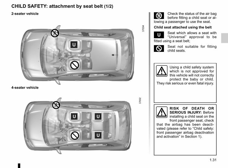
CHILD SAFETY: attachment by seat belt (1/2)
RISK OF DEATH OR SERIOUS INJURY: Before installing a child seat on the front passenger seat, check
that the airbag has been deacti-vated (please refer to “Child safety: front passenger airbag deactivation and activation” in Section 1).
Using a child safety system which is not approved for this vehicle will not correctly protect the baby or child.
They risk serious or even fatal injury.
³ Check the status of the air bag before fitting a child seat or al-
lowing a passenger to use the seat.Child seat attached using the belt
¬ Seat which allows a seat with “Universal” approval to be
fitted using a seat belt;
² Seat not suitable for fitting child seats.
2-seater vehicle
4-seater vehicle

1.32
CHILD SAFETY: attachment by seat belt (2/2)The table below summarises the information already shown on the diagram on the previous page, to ensure the regula-tions in force are respected.
2 and 4-seater vehicles: Child seat attached using the seat belt
Type of child seat Weight of the child Front passenger seat (1) (5) Rear side seats
Carrycot fitted across the vehicleGroup 0 < 10 kg X U (2)
Rear-facing shell seatGroup 0 and 0+ < 13 kg U U (3)
rear-facing seatGroup 0+ and 1 < 13 kg and 9 to 18 kg U U (3)
Forward-facing seatGroup 1 9 to 18 kg U U (4)
Booster seatGroup 2 and 3
15 to 25 kg and 22 to 36 kg U U (4)
U = Seat which allows a child seat with “Universal” approval to be installed using a seat belt; check that it can be fitted.(1) raise the seat to the maximum and position it as far back as possible, tilting the seatback slightly (approximately 25°).(2) A carrycot can be installed across the vehicle and will take up at least two seats. Place the child with its feet nearest the door.(3) Move the front seat as far forward as possible to install a rear-facing child seat, then move back the seat in front as far as it will
go, although without allowing it to come into contact with the child seat.(4) Forward-facing child seat; position the seatback of the child seat in contact with the seatback of the vehicle seat. In all situa-
tions, remove the rear headrest of the seat on which the child seat is positioned. This must be done before fitting the child seat (please refer to the section entitled “Rear headrests” in Section 3).
(5) RISK OF DEATH OR SERIOUS INJURY: before installing a child seat on the front passenger seat, check that the airbag has been deactivated (refer to “Child safety: front passenger airbag deactivation, activation” Section 1).

1.33
CHILD SAFETY: attachment using the ISOFIX system (1/3)
RISK OF DEATH OR SERIOUS INJURY: Before installing a child seat on the front passenger seat, check
that the airbag has been deacti-vated (please refer to “Child safety: front passenger airbag deactivation and activation” in Section 1).
Using a child safety system which is not approved for this vehicle will not correctly protect the baby or child.
They risk serious or even fatal injury.
³ Check the status of the air bag before fitting a child seat or al-
lowing a passenger to use the seat.
² Seat which does not allow a child seat to be fitted.
4-seater vehicle Child seat attached using the ISOFIX mounting
ü Seat which allows an ISOFIX child seat to be fitted.
±The seats ISOFIX are fitted with an anchorage point which allows a forward-facing ISOFIX child seat with “Universal” approval to be attached. The anchorage points are located in the boot for the rear seats, and on the seatbacks for the front seats.The size of the ISOFIX child seat is in-dicated by a letter:– A, B and B1: for forward-facing seats
in group 1 (9 to 18 kg);– C and D: shell seat or rear-facing
seats in group 0+ (less than 13 kg) or group 1 (9 to 18 kg);
– E: rear-facing shell seats in group 0 (less than 10 kg) or 0+ (less than 13 kg);
– F and G: carrycots in group 0 (less than 10 kg).

1.34
CHILD SAFETY: attachment using the ISOFIX system (2/3) The table below summarises the information already shown on the diagram on the previous page, to ensure the regula-tions in force are respected.
4-seater vehicle: Fitting a child seat ISOFIX.
Type of child seat Weight of the child Seat size Front passenger seat (1) (2) Rear side seats
Carrycot fitted across the vehicleGroup 0
< 10 kg F, G X IL (3)
Rear-facing shell seatGroup 0 and 0+ < 13 kg E IL IL (4)
rear-facing seatGroup 0+ and 1
< 13 kg and 9 to 18 kg
C IL X
D IL IL (4)
Forward-facing seatGroup 1 9 to 18 kg A, B, B1 IUF - IL IUF - IL (5)
Booster seatGroup 2 and 3
15 to 25 kg and 22 to 36 kg - X X
(1) RISK OF DEATH OR SERIOUS INJURY: before installing a child seat on the front passenger seat, check that the airbag has been deactivated (refer to “Child safety: front passenger airbag deactivation, activation” Section 1).

1.35
CHILD SAFETY: attachment using the ISOFIX system (3/3)X = Seat not suitable for fitting child seats ISOFIX.IUF/IL = On equipped vehicles, seat which allows an approved “Universal”/“semi-universal” or “vehicle specific” child seat to be
attached using the ISOFIX system; check that it can be fitted.(2) raise the seat to the maximum and position it as far back as possible, tilting the seatback slightly (approximately 25°).(3) A carrycot can be installed across the vehicle and will take up at least two seats. Place the child with its feet nearest the door.(4) Move the front seat as far forward as possible to install a rear-facing child seat, then move back the seat in front as far as it will
go, although without allowing it to come into contact with the child seat.(5) Forward-facing child seat; position the seatback of the child seat in contact with the seatback of the vehicle seat. In all situa-
tions, remove the rear headrest of the seat on which the child seat is positioned. This must be done before fitting the child seat (please refer to the section entitled “Rear headrests” in Section 3).

1.36
CHILD SAFETY: deactivating, activating the front passenger air bag (1/3)
Deactivating the front passenger airbag(on equipped vehicles)Before installing a child seat on the front passenger seat:– check that the child seat can be in-
stalled on this seat;– it is essential to deactivate the
airbagfor a rear-facing child seat.
12
The passenger airbag must only be deactivated or acti-vated when the vehicle is stationary.
If it is interfered with when the ve-hicle is being driven, indicator lights
å and © will come on.Switch the ignition off then on again to reset the airbag in accordance with the lock position.
To deactivate the airbag: stationary vehicle, ignition off, push and turn lock 1 to the OFF position.With the ignition on, you must check
that the warning light ] on the dis-play 2 is switched on.This light remains permanently lit to let you know that you can fit a child seat.

1.37
3
DANGERSince operation of the front passenger airbag is not compatible with the po-
sition of a rear-facing child seat, NEVER fit a rear-facing child re-straint system in a seat protected by an ACTIVATED front AIRBAG. This can lead to the DEATH of the CHILD or SERIOUS INJURY.
The markings on the dashboard and labels A on each side of passenger sun blind 3 (example: label shown above) remind you of these instructions.
A
A
CHILD SAFETY: deactivating, activating the front passenger air bag (2/3)

1.38
CHILD SAFETY: deactivating, activating the front passenger air bag (3/3)
The passenger airbag must only be deactivated or acti-vated when the vehicle is stationary.
If it is interfered with when the ve-hicle is being driven, indicator lights
å and © will come on.Switch the ignition off then on again to reset the airbag in accordance with the lock position.
12
Activating the front passenger airbagYou should reactivate the airbag as soon as you remove the child seat from the front passenger seat to ensure the protection of the front passenger in the event of an impact.
Operating faultsIt is forbidden to fit a rear-facing child seat to the front passenger seat if the airbag activation/deactivation system is faulty.Allowing any other passenger to sit in that seat is not recommended.Contact your approved dealer as soon as possible.
To reactivate the airbag : with the vehicle stoppedand the ignition off, push and turn lock 1 to the ON position.With the ignition switched on, you must
check that the warning light ] is
out and that the warning light comes on the display 2 after each start-up for around 60 seconds.The front passenger airbag is activated.

1.39
Door mirrors with manual adjustmentTo adjust the door mirror, move switch 2.
Door mirrors with electrical adjustmentWith the ignition on, turn the button 3:– position C to adjust the left-hand
door mirror;– position E to adjust the right-hand
door mirror.D is the inactive position.
Heated door mirrorsWith the engine running, mirror de-icing is activated simultaneously with rear screen de-icing/demisting.
Interior rear view mirrorIts position can be adjusted. For night driving, to avoid being dazzled by the headlights of the car behind you, flip the small lever 1 located behind the rear view mirror.
REAR VIEW MIRRORS
For safety reasons, carry out any adjustments when the vehicle is not being driven.
1 2
The driver’s door mirror may have two clearly defined zones. Zone B shows what can normally be seen in an ordinary rear view mirror. Zone A increases rear side visibility.Objects in the mirror are closer than they appear.
A B
3 CD
E
A B

1.40
DRIVING POSITION: LEFT-HAND DRIVE (1/2)
2 31 54 6 87 10 3 211 12
13
15
16
18
17
24 1920212225 23
14
9

1.41
DRIVING POSITION: LEFT-HAND DRIVE (2/2)
1 Stalk for:– direction indicator lights;– exterior lights;– front fog lights;– rear fog lights.
2 Side air vent.
3 Side window demister outlet.
4 Driver Airbag and horn location.
5 Instrument panel.
6 Stalk for:– windscreen and rear screen
wash/wipe;– trip computer and warning
system information readout.
7 Switch for:– hazard warning lights;– electric door locking.
The equipment fitted, described below, DEPENDS ON THE VERSION AND COUNTRY.
8 Centre air vent.
9 Windscreen demister outlet.
10 Multimedia/radio touchscreen.
11 Glovebox.
12 Passenger Airbag location.
13 Heating or air conditioning con-trols.
14 Token holder.
15 Main switch for:– speed limiter;– cruise control.
16 Handbrake.
17 ECO mode switch.
18 Gear lever.
19 Ignition switch.
20 Radio and/or navigation system remote control.
21 Multimedia system voice control button.
22 Steering wheel adjustment control.
23 Cruise control/speed limiter con-trol.
24 Headlight adjustment control.
25 Controls for:– activation/deactivation of the
parking distance control system;– activation/deactivation of the
Stop and Start function;– activation/deactivation of the
lane departure warning func-tion.

1.42
DRIVING POSITION: RIGHT-HAND DRIVE (1/2)
1 5 6 7 9 11 122
13
1820
24
25
1043
19 17
22
2316
2 8
14
15
21
2 1

1.43
DRIVING POSITION: RIGHT-HAND DRIVE (2/2)The equipment fitted, described below, DEPENDS ON THE VERSION AND COUNTRY.
1 Side window demister outlet.
2 Side air vent.
3 Passenger Airbag location.
4 Heating or air conditioning con-trols.
5 Multimedia/radio touchscreen.
6 Centre air vent.
7 Switch for:– hazard warning lights;– electric door locking.
8 Windscreen demister outlet.
9 Stalk:– direction indicator lights;– exterior lights;– front fog lights;– rear fog lights.
10 Instrument panel.
11 Driver Airbag and horn location.
12 Stalk for:– windscreen and rear screen
wash/wipe;– trip computer and warning
system information readout.
13 Multimedia system voice control button.
14 Radio and/or navigation system remote control.
15 Controls for:– activation/deactivation of the
parking distance control system;– activation/deactivation of the
Stop and Start function;– activation/deactivation of the
lane departure warning func-tion.
16 Ignition switch.
17 Headlight adjustment control.
18 Cruise control/speed limiter con-trols.
19 Steering wheel adjustment control.
20 Gear lever.
21 Token holder.
22 Main switch for:– speed limiter;– cruise control.
23 ECO mode switch.
24 Handbrake.
25 Glovebox.

1.44
WARNING LIGHTS (1/5)
š Side light warning light
á Main beam headlight tell-tale
k Dipped beam headlight tell-tale
g Front fog light tell-tale
Rear fog light telltale
c Left-hand direction indicator tell-tale
b Right-hand direction indica-tor tell-tale
å Airbag warning lightThis lights up when the ignition
is switched on and goes out after a few seconds.If it does not come on when the igni-tion is switched on, or comes on when the engine is running, there is a fault in the system.Contact your approved Dealer as soon as possible.
M Low fuel level warning lightThis lights up when the ignition
is switched on, alongside a beep, and goes out after a few seconds.If it comes on when driving and is ac-companied by a beep, fill up with fuel as soon as possible. There is only ap-proximately 30 miles (50 km) worth of fuel left.
A
If no lights or sounds are ap-parent, this indicates a fault in the instrument panel. This indicates that it is essential
to stop immediately (as soon as traf-fic conditions allow). Ensure that the vehicle is correctly immobilised and contact an approved Dealer.
Instrument panel A: lights up when the ignition is switched on.With the lights on, you can adjust the brightness by turning the knob 1.
Warning light © means you should drive very carefully to an authorised dealer as soon as possible. Failure to follow this rec-ommendation risks damaging your vehicle.
Warning light ® re-quires you to stop immedi-ately, for your own safety, as soon as traffic conditions
allow. Switch off the engine and do not restart it. Contact an approved Dealer.
The display of information shown below DEPENDS ON THE VEHICLE EQUIPMENT AND COUNTRY.
1

1.45
WARNING LIGHTS (2/5)
®STOP lightThis lights up when the ignition
is switched on and goes out as soon as the engine is started. It lights up at the same time as other warning lights, and is accompanied by a beep.It requires you to stop immediately, for your own safety, as soon as traffic con-ditions allow. Switch off the engine and do not restart it.Contact an approved Dealer.
À Oil pressure warning lightThis lights up when the ignition
is switched on and goes out after a few seconds.If it comes on on the road, accompa-nied by the ® warning light and a beep, stop immediately and cut the ig-nition.Check the oil level. If the level is normal, the indicator light is being lit by some-thing else. Contact an approved Dealer.
©Warning lightThis lights up when the ignition
is switched on and goes out as soon as the engine is started. It may light up in conjunction with other warning lights.You should drive very carefully to an authorised dealer as soon as possible. Failure to follow this recommendation risks damaging your vehicle.
D Handbrake on and brake cir-cuit incident warning light
This comes on when the ignition is switched on and goes out as soon as the handbrake is released.If it comes on during braking and is ac-companied by the ® warning light and a beep, it indicates that the fluid level in the circuit is low or that there is a braking system fault.Stop as soon as traffic conditions allow and contact an approved Dealer.
Ú Battery charge warning lightThis lights up when the ignition
is switched on and goes out after a few seconds.If it comes on on the road, accompa-nied by the ® warning light and a beep, this indicates an overload or dis-charge in the electrical circuit.Stop as soon as traffic conditions allow and contact an approved Dealer.
The display of information shown below DEPENDS ON THE VEHICLE EQUIPMENT AND COUNTRY.
A

1.46
x Anti-lock braking warning light
This lights up when the ignition is switched on and goes out after a few seconds.If it lights up when you are driving, it in-dicates a fault in the anti-lock braking system.Braking will then be as normal, without the ABS. Contact an approved Dealer as soon as possible.
Ô Coolant temperature warn-ing light
This comes on when the ignition is switched on.If it turns red, stop and let the engine idle for a minute or two.The temperature should lower and the warning light should return to a blue colour. If not, stop the engine. Let the engine cool down before checking the coolant.Contact an approved Dealer.
WARNING LIGHTS (3/5)
Ä Toxic Fume Filter System Warning Light
On vehicles which are equipped with it, this light comes on when the engine is started and, depending on the vehicle, when the ignition is switched off if the vehicle is in the engine standby phase (refer to the information on the 'Stop and Start Function' in section 2) then goes out.– If it lights up continuously, consult an
authorised dealer as soon as possi-ble;
– If it flashes, reduce the engine speed until the light stops flashing. Contact an approved dealer as soon as pos-sible.
Please refer to the information on “Maintenance and anti-pollution advice” in Section 2.
Warning light for electronic stability program ( ESC ) and
traction control systemThis lights up when the ignition is switched on and goes out after a few seconds.There are several reasons for the warn-ing light to come on: please refer to the information on “Dynamic driving control: ESC” and “Traction control” in Section 2.
Lane departure system warning light
Please refer to the information on “Lane departure warning” in Section 2.
Φ Speed limiter and cruise control indicator lights
See the information on the “Speed lim-iter” and “Cruise control” in Section 2.
The display of information shown below DEPENDS ON THE VEHICLE EQUIPMENT AND COUNTRY.

1.47
WARNING LIGHTS (4/5)
2 Door(s) open warning light
Engine standby warning light
Please see information about “Stop and Start function” in Section 2.
Unavailability of engine standby warning light
Please see information in the para-graph on “Stop and Start Function” in Section 2.
Mode warning light ECOThis comes on when ECO
mode is activated. Please refer to the information on “Driving advice, Eco-driving” in Section 2.
Ò Electronic fault warning lightThis lights up when the ignition
is switched on and goes out after a few seconds.If it comes on when driving, this indi-cates a fault in the injection computer.Contact your approved Dealer as soon as possible.
Š‰ Gear change indicator.This lights up to advise you to
change to a higher gear (up arrow) or lower gear (down arrow).
Tyre pressure loss warningPlease refer to the information
on the “Tyre pressure loss warning” in Section 2.
The display of information shown below DEPENDS ON THE VEHICLE EQUIPMENT AND COUNTRY.
U Variable power-assisted steering warning light
This comes on when the ignition is switched on and goes out after a few seconds.If it lights up when you are driving, this indicates a fault in the system. Consult an approved Dealer as soon as possi-ble.
A

1.48
Central display B: lights up when the ignition is switched on.
B
ß Seat belt reminder warning lightsPlease see the information on “Seat belts” in Section 1.
¹ Front passenger airbag deac-tivated warning lightPlease see the information on “Seat belts” in Section 1.
Front passenger airbag acti-vated warning lightPlease see the information on “Seat belts” in Section 1.
WARNING LIGHTS (5/5)The display of information shown below DEPENDS ON THE VEHICLE EQUIPMENT AND THE COUNTRY.

1.49
DISPLAYS AND INDICATORS
Speedometer 1 and 2(km or miles per hour)The indicator 2 is provided as an indica-tion. Check your speed according to the approved speedometer only 1.
Overspeed buzzerDepending on the vehicle, a warning beep sounds for approximately 10 sec-onds every 30 seconds, as long as the vehicle is travelling in excess of 75 mph (120 km/h).
Fuel gauge 3
Automatic gearbox display 4This indicates the gear engaged (de-pending on the vehicle). Refer to the in-formation on the “Automatic gearbox” in Section 2.
1
4
3
2

1.50
ON-BOARD COMPUTER: general information (1/2)
On-board computer 1It includes the following functions:– distance travelled;– journey settings;All these functions are described on the following pages.
Display selection keys 2 and 3Scroll through the following information upwards (key 2) or downwards (key 3) by pressing briefly and successively (the display depends on the vehicle equipment and country).a) total mileage recorder;b) trip mileage recorder;c) fuel used;d) average fuel consumption;e) Current fuel consumption;f) estimated range;
2
3
1
g) distance travelled since the last reset;
h) average speed;i) mileage before next service/oil
change;j) Reset the tyre pressurek) cruise control/speed limiter pro-
grammed speed;l) time;m) temperature.

1.51
ON-BOARD COMPUTER: general information (2/2)
Resetting the trip mileageWith “trip mileage recorder” selected on the display, press button 2 or 3 until the mileage recorder resets to zero.
Resetting the journey parameters (reset button)With one of the trip parameters selected as the display, press and hold button 2 or 3 until the display resets.
Interpreting some of the values displayed after resettingThe values showing average fuel con-sumption, range and average speed will become more stable and reliable the further you travel after pressing the reset button.For the first few miles after pressing the reset key you will notice that the range increases as you travel. This range takes into account the average fuel consumption since the last time the reset button was pressed. Therefore, the average fuel consumption may de-crease when:– the vehicle stops accelerating;– the engine reaches its operating
temperature (if the engine was cold when the reset key was pressed);
– when driving from an urban area onto the open road.
Automatic resetting of the journey parametersResetting occurs automatically when the maximum value of any of the pa-rameters is exceeded.
2
3

1.52
ON-BOARD COMPUTER: trip settings (1/4)The display of information shown below DEPENDS ON THE VEHICLE EQUIPMENT AND COUNTRY.
Examples of selections Interpreting the display selected
a) Total mileage recorder.101778 km
b) Trip mileage recorder.112.4 km
c) Trip settings.Fuel used.Fuel consumed since the last reset.
5.8 L/100
d) Average fuel consumption since the last reset.The value is displayed after having travelled at least 400 metres since the last reset.
5.8 L/100

1.53
ON-BOARD COMPUTER: trip settings (2/4)The display of information shown below DEPENDS ON THE VEHICLE EQUIPMENT AND COUNTRY.
Examples of selections Interpreting the display selected
e) Current fuel consumption.This value is displayed after a speed of approximately 20 mph (30 km/h) is reached.
7.4 L/100
f) Estimated range with remaining fuel.The value is displayed after driving 400 metres.
541 km
g) Distance travelled since last reset.522 km
h) Average speed since the last reset.The value is displayed after driving 400 metres.
123.4 km/H

1.54
ON-BOARD COMPUTER: trip settings (3/4)The display of information shown below DEPENDS ON THE VEHICLE EQUIPMENT AND COUNTRY.
Examples of selections Interpreting the display selected
i) Mileage before service or oil change.Distance remaining until the next service (displayed in miles (kilometres) or days), then when the service nears, the warning light © is displayed on the instrument panel.The vehicle requires a service as soon as possible.
Resetting: To reset the mileage before the next service/oil change, press and hold button 2 or 3 for approximately 10 seconds until the display shows the mileage before service/oil change without flashing.

1.55
The display of information shown below DEPENDS ON THE VEHICLE EQUIPMENT AND COUNTRY.
ON-BOARD COMPUTER: trip settings (4/4)
Examples of selections Interpreting the display selected
SET
j) Reset the tyre pressure.Please refer to the information on the “Tyre pressure loss warning” in Section 2.
90 km/Hk) Cruise control and speed limiter programmed speed.
Refer to the information on the “Speed limiter” and “Cruise control” in Section 2.
16:30 l) Time.Please refer to the information on the “Clock and exterior temperature” in Section 1.

1.56
Wait a few seconds, the minutes will flash: repeatedly press or press and hold button 3 or 4 to set the time.When setting is complete, the hours and minutes remain displayed continu-ously for 5 seconds: your setting is reg-istered.You may change the display.
Display ATo access the display 2 for setting the time, press button 3 or 4 on the stalk 1.Wait a few seconds; the hours and min-utes will begin to flash. You are now in setting mode, press and hold button 3 or 4 to set the hour.Once the minutes flash, repeatedly press or press and hold button 3 ou 4 to set the time.
CLOCK AND EXTERIOR TEMPERATURE (1/2)
3
4
If the power supply is cut (battery disconnected, supply wire cut, etc.), the clock must be reset.We recommend that you do not adjust these settings while driving.
12:00
2
1 1A

1.57
Display BVehicles fitted with touch-screen multimedia, navigation aid systems, telephones, etc.Refer to the separate instructions for the function to understand the special features of this equipment.
External temperature indicatorSpecial note:When the exterior temperature is - 3°C to + 3°C, the °C characters flash (sig-nalling a risk of ice on the road).
External temperature in-dicatorAs ice formation is related to climatic exposure, local
air humidity and temperature, the external temperature alone is not sufficient to detect ice.
CLOCK AND EXTERIOR TEMPERATURE (2/2)
If the power supply is cut (battery disconnected, supply wire cut, etc.), the clock must be reset.We recommend that you do not adjust these settings while driving.
B

1.58
Daytime running lights function(front lights only)If fitted to the vehicle, the daytime running lights come on automatically when the engine is started or, depend-ing on the vehicle, when the ignition is switched on.
EXTERIOR LIGHTING AND SIGNALS (1/3)
š Side lightsTurn the ring 2 until the symbol
is opposite mark 3.An indicator light on the instrument panel will come on.
1
Before driving at night, check that the electrical equipment is operating correctly and adjust the headlight beams (if your vehicle is not carrying its normal load). As a general precaution, check that the lights are not ob-scured (by dirt, mud, snow or objects being transported).
k Dipped beam headlights
Manual operationTurn the ring 2 until the symbol is oppo-site mark 3. This indicator light on the instrument panel comes on.
Automatic operation(depending on vehicle)Turn ring 2 until the AUTO symbol is op-posite mark 3: with the engine running, the dipped beam headlights switch on or off automatically depending on the brightness of the light outside, without any action on stalk 1.
When driving on the left in a left-hand drive vehicle (or vice versa), drivers must re-adjust their lights throughout their stay (see “Adjusting headlight beams” in Section 1).
31 2

1.59
EXTERIOR LIGHTING AND SIGNALS (2/3)
Switching off the lightsThere are two possibilities:– manually, move ring 2 to position 0;– automatically, if the ring 2 is in
AUTO position and if the main beam headlights are not switched on. The lights will go out automatically when the engine is switched off, the dri-ver’s door is opened or the vehicle is locked. In this case, the next time the engine is started, the lights will be switched back on according to the position of the ring 2, taking into ac-count the exterior light level, without moving the stalk 1.
Lights-on reminder buzzerA warning beep sounds when the driv-er’s door is opened to warn you that the lights are still on.
g Front fog lightsTurn the centre ring 4 on the
stalk 1 until the symbol is opposite mark 3, then release it.Operation of the fog lights depends on the exterior lighting position selected, and an indicator light will light up on the instrument panel.
Cornering lights functionWhenever the dipped beam headlights are on and under certain conditions (at speed, the steering wheel at an angle, in forward gear, the indicator lights on, etc.), when taking a corner one of the front fog lights will come on to light the inside of the bend.
1 2
á Main beam headlightsWith the engine running and
the dipped beam headlights on, push stalk 1. This indicator light on the instru-ment panel comes on.To return to the dipped headlight posi-tion, pull stalk 1 towards you again.
43

1.60
EXTERIOR LIGHTING AND SIGNALS (3/3)
Rear fog lightTurn the centre ring 4 on
the stalk until the symbol is opposite mark 3, then release it.Depending on the vehicle, the stalk re-turns to the initial position or stays in position.Operation of the fog lights depends on the exterior lighting selected, and an in-dicator light will light up on the instru-ment panel.To avoid inconveniencing other road users, remember to switch off the rear fog light when it is no longer needed.
Turning off the fog lightsThere are two possibilities:– manually, depending on the vehi-
cle, turn the ring 4 again to bring the mark 3 opposite the symbol for the fog light that you want to switch off, or bring the ring 4 into position 0. The corresponding indicator light will go out on the instrument panel;
– the lights will go out automati-cally when the engine is switched off or the vehicle is locked, and the fog lights when the driver’s door is opened.
The front and rear fog lights switch off when the exterior lights are switched off.
When driving in fog or snow, or when transporting objects which are higher than the roof, the headlights do not come on automatically.Switching on the fog lights remains the responsibility of the driver: the indicator lights on the instrument panel inform you whether the fog lights are lit (indicator light on) or not (indicator light not on).
41 3

1.61
é Hazard warning lights Press switch 2.
This switch activates all four direction indicators and the side indicator lights simultaneously. It must only be used in an emergency to warn drivers of other vehicles that you have had to stop in an area where stopping is prohibited or unexpected, or that you are obliged to drive under special conditions.Depending on the vehicle, the hazard warning lights may come on auto-matically under heavy deceleration. You can switch them off by pressing switch 2 once.
Direction indicatorsMove stalk 1 parallel to the steering wheel and in the direction you are going to turn it.
One-touch modeWhen driving, it is possible that the steering wheel may not be turned suf-ficiently to return the stalk automatically to its starting position.In this case, move the stick 1 to half-way, then release it: it will return to its initial position and the indicator light flashes three times.
HornPress steering wheel boss A.
Headlight flasherPull stalk 1 towards you to flash the headlights.
AUDIBLE AND VISUAL SIGNALS
A
12

1.62
HEADLIGHT BEAM ADJUSTMENT (1/2)
On vehicles fitted with this function, control A allows you to adjust the height of the beams according to the load.Turn control A downwards to lower the headlights and upwards to raise them.
A
Examples of positions for adjusting control A according to the load
0 Driver alone or with front passenger
1 All seats occupied
2 All seats occupied and the boot laden
3 Driver only with the boot laden
The table below gives some examples. In all cases, adjust control A according to the vehicle load so that the road can be seen and other drivers are not dazzled.

1.63
Once the adjustment has been done, make sure the bonnet is repositioned and closed properly.
HEADLIGHT BEAM ADJUSTMENT (2/2)
Temporary adjustmentOpen the bonnet (please refer to the in-formation on the “Bonnet” in Section 4) and slide it sideways to access the screw 1 and marking B.Note: Take care not to scratch the vehi-cle paintwork.For each headlight, using a screw-driver, turn the screw 1 by a quarter turn towards the - symbol to lower the beams.Return to the starting point once your trip is over: turn the screw 1 by a quar-ter turn towards the + symbol to raise the beams.
B
1
When driving on the left in a left-hand drive vehicle (or vice versa), you must adjust your lights temporarily for the duration of your trip.
For your safety, do not remove the bonnet holding straps. Risk of the bonnet falling on the road surface.

1.64
With the ignition on, move stalk 1– A park.– B intermittent wiping.
Depending on the vehicle, the wipers may stop for a few seconds between wipes. It is possible to change the time between sweeps by turning ring 2.
– C normal wiping speed.– D fast wiping speed.
Special noteWhen driving, the wiping speed slows down whenever the vehicle stops. For example: the speed will change from a fast wiping speed to normal wiping speed.As soon as the vehicle moves off, wiping will return to the speed originally selected.Any action on stalk 1 overrides and cancels automatic operation.Starting the vehicle with the stalk in position D triggers a slow continuous sweeping movement. Adjusting the stalk to position D is necessary to trig-ger a rapid continuous sweeping move-ment.
Vehicles with automatic wiper functionWith the engine running, move stalk 1– A park.– B automatic wiper function
When this position is selected, the system detects water on the wind-screen and triggers the wipers at a suitable wiping speed:
– E: minimum sensitivity– F: maximum sensitivityNB: in foggy weather or during snowfalls, the wiping is not automati-cally triggered and remains under the driver’s control.
– C normal wiping speed.– D fast wiping speed.
WINDSCREEN WASH, WIPE (1/2)
ABC
D
11
Position C is accessible with the ig-nition on. Positions B and D are ac-cessible only with the engine run-ning.
Positions B, C and D are accessible with the ignition on.
E
F
2

1.65
Before any action involving the windscreen (washing the vehicle, de-icing, clean-ing the windscreen, etc.)
return stalk 1 to position A (park).Risk of injury and/or damage.
Windscreen washerWith the ignition on, pull stalk 1 to-wards you.A brief pull will trigger a single sweep of the wipers, in addition to the wind-screen washer.A longer pull triggers, as well as the windscreen washer, continuous sweep-ing until the end of the request, then three return sweeps, then after a few seconds, a fourth.
WINDSCREEN WASH, WIPE (2/2)
ABC
D
1
When working in the engine compartment, ensure that the windscreen wiper stalk is in position A (park).
Risk of injury.
Do not try to lift the wiper blades. They cannot remain detached from the windscreen. To replace the blades, refer to Section 5: “Wiper blades”.
Efficiency of a wiper bladeCheck the condition of the wiper blades. How long they last depends on you:– it must remain clean: clean the
blade and the screen regularly with soapy water;
– do not use it when the screen is dry;
– free it from the screen when it has not been used for a long time.
In all cases, replace it as soon as it begins to lose efficiency: approx-imately once a year. Refer to the paragraph on “Wiper blades” in Section 5.
Precaution for using the wipers– In freezing or snowy weather
conditions, clear the screen before starting the wipers (risk of motor overheating);
– ensure that no objects are ob-structing the travel of the blade.

1.66
p Rear windscreen wash/wiper
With ignition on, turn the end of the stalk 1 to bring the mark 2 in line with the symbol. When the stalk is released, it returns to the rear wipe position.A short pull triggers the rear windscreen wipers.A prolonged action triggers, in addition to the rear windscreen wipers, a contin-uous sweep until the stalk is released, then two return wipes followed by a third, after a few seconds.
Y Speed-dependent timed rear screen
wiperWith the ignition on, turn the end of the stalk 1 to align the mark 2 with the symbol.Wiping frequency varies with speed.
REAR SCREEN WASHER, WIPER (1/2)
1
2
Before any action on the windscreen (washing the vehicle, de-icing, cleaning the windscreen, etc.), return
the stalk 1 to the park position.Risk of injury or damage.
Special noteIf the windscreen wipers are operat-ing or are in automatic mode, the rear screen wiper wipes intermittently when reverse gear is engaged.Depending on the vehicle, you may be able to deactivate this function via the multimedia screen. Please see the equipment instructions for further infor-mation.

1.67
REAR SCREEN WASHER, WIPER (2/2)
Do not use the wiper arm to open or close the tailgate.
Efficiency of a wiper bladeCheck the condition of the wiper blades. How long they last depends on you:– it must remain clean: clean the
blade and the screen regularly with soapy water;
– do not use it when the screen is dry;
– free it from the screen when it has not been used for a long time.
In all cases, replace it as soon as it begins to lose efficiency: approx-imately once a year. Refer to the paragraph on “Wiper blades” in Section 5.
Precaution for using the wipers– In freezing or snowy weather
conditions, clear the screen before starting the wipers (risk of motor overheating);
– ensure that no objects are ob-structing the travel of the blade.

1.68
Petrol versionIt is essential to use unleaded petrol. The octane rating (RON) must comply with the information given on the label on the cover A. Please refer to the in-formation on «Engine specifications» in Section 6.
FUEL TANK (1/2)
A
B2
1
Fuel gradeUse a high-grade fuel that complies with the legislation in force in each country and which must comply with the specifications given on the label on the cover A. Refer to the information on “Engine specifications” in Section 6.
Useful capacity of fuel tank: approximately 28 litres or 35 litres, de-pending on the vehicle.To open cover A, place your finger into recess B. When filling, use the cap holder 1 on the cover A to secure the cap 2.
After filling, check that the cap and cover are closed.
Fuel filler cap: this is spe-cific.If you have to replace it, make sure it is identical
to the original cap. Contact an ap-proved Dealer.Never place the cap near a source of heat or flame.Do not wash the filler area with a high-pressure washer.
Do not use ethanol-based fuel if your vehicle is not compatible with this fuel.Do not add additive to the
fuel –otherwise you risk damaging the engine.
Fuel types that conform to European standards with which the engines of vehicles sold in Europe are compat-ible: refer to the “Engine specifica-tions” in section 6.

1.69
FUEL TANK (2/2)
Filling with fuelWith the ignition off, insert the nozzle and insert it fully before turning it on to fill the fuel tank (risk of splashing).Keep the nozzle in this position through-out the entire filling operation.When the pump cuts out automatically at the end of the filling procedure, a maximum of two further filling attempts may be made, as there must be suffi-cient space in the fuel tank to allow for expansion.Make sure that no water enters the fuel tank during filling. The cover A and its surround must remain clean.
Petrol versionsUsing leaded petrol will damage the antipollution system and may lead to a loss of warranty.To ensure that the fuel tank is not filled with leaded petrol, the fuel tank filler neck contains a restrictor fitted with a foolproof system which only allows the nozzle for unleaded petrol to be used (at the pump).
Vehicle fitted with the Stop and Start functionTo fill up with fuel, the engine must be stopped (and not on standby): stop the engine (please refer to the information on “Starting and stop-ping the engine” in Section 2).
Persistent fuel odourIf you notice a persistent fuel odour you should:
– stop the vehicle as soon as traf-fic conditions allow and switch off the ignition;
– switch on the hazard warning lights and ask your passengers to leave the vehicle and stay clear of the traffic;
– contact an approved Dealer.
No modifications what-soever are permitted on any part of the fuel supply system (electronic units,
wiring, fuel circuit, injectors, pro-tective covers, etc.) as this may be dangerous (unless undertaken by qualified Network personnel).

1.70

2.1
Section 2: Driving(Advice on use relating to fuel economy and the environment)
Running in . . . . . . . . . . . . . . . . . . . . . . . . . . . . . . . . . . . . . . . . . . . . . . . . . . . . . . . . . . . . . . . . . . . . . 2.2Starting, stopping the engine . . . . . . . . . . . . . . . . . . . . . . . . . . . . . . . . . . . . . . . . . . . . . . . . . . . . . . . 2.3Standing start procedure . . . . . . . . . . . . . . . . . . . . . . . . . . . . . . . . . . . . . . . . . . . . . . . . . . . . . . . . . . 2.4Stop and Start Function . . . . . . . . . . . . . . . . . . . . . . . . . . . . . . . . . . . . . . . . . . . . . . . . . . . . . . . . . . . 2.5Special features of petrol versions . . . . . . . . . . . . . . . . . . . . . . . . . . . . . . . . . . . . . . . . . . . . . . . . . . 2.9Gear lever/Handbrake . . . . . . . . . . . . . . . . . . . . . . . . . . . . . . . . . . . . . . . . . . . . . . . . . . . . . . . . . . . . 2.10Driving advice, Eco-driving . . . . . . . . . . . . . . . . . . . . . . . . . . . . . . . . . . . . . . . . . . . . . . . . . . . . . . . . 2.11Maintenance and antipollution advice . . . . . . . . . . . . . . . . . . . . . . . . . . . . . . . . . . . . . . . . . . . . . . . . 2.15Environment . . . . . . . . . . . . . . . . . . . . . . . . . . . . . . . . . . . . . . . . . . . . . . . . . . . . . . . . . . . . . . . . . . . 2.16Tyre pressure loss warning . . . . . . . . . . . . . . . . . . . . . . . . . . . . . . . . . . . . . . . . . . . . . . . . . . . . . . . . 2.22Driver correction devices/aids . . . . . . . . . . . . . . . . . . . . . . . . . . . . . . . . . . . . . . . . . . . . . . . . . . . . . . 2.26Lane departure warning. . . . . . . . . . . . . . . . . . . . . . . . . . . . . . . . . . . . . . . . . . . . . . . . . . . . . . . . . . . 2.30Speed limiter . . . . . . . . . . . . . . . . . . . . . . . . . . . . . . . . . . . . . . . . . . . . . . . . . . . . . . . . . . . . . . . . . . . 2.32Cruise control . . . . . . . . . . . . . . . . . . . . . . . . . . . . . . . . . . . . . . . . . . . . . . . . . . . . . . . . . . . . . . . . . . 2.35Parking distance control . . . . . . . . . . . . . . . . . . . . . . . . . . . . . . . . . . . . . . . . . . . . . . . . . . . . . . . . . . 2.39Reversing camera . . . . . . . . . . . . . . . . . . . . . . . . . . . . . . . . . . . . . . . . . . . . . . . . . . . . . . . . . . . . . . . 2.41Automatic gearbox. . . . . . . . . . . . . . . . . . . . . . . . . . . . . . . . . . . . . . . . . . . . . . . . . . . . . . . . . . . . . . . 2.43

2.2
“On” position MThe ignition is switched on:
Start position DIf the engine fails to start at the first attempt, the key must be turned back before the starter can be activated again. Release the key as soon as the engine starts.
vehicles fitted with an automatic gearboxBefore starting, move the lever to posi-tion P.
“Stop and steering lock” position StTo lock: remove the key and turn the steering wheel until the steering column locks.To unlock: turn the key and the steering wheel slightly.
“Accessories” position AWhen the ignition is switched off, any accessories (radio, etc.) will continue to function.
RUNNING IN/STARTING, STOPPING THE ENGINE (1/2)
Running inPetrol versionFor the first 600 miles (1,000 km), do not exceed 78 mph (130 km/h) in the highest gear, or 3,000 to 3,500 rpm.You may only expect top performance from your vehicle after approximately 1,800 miles (3,000 km).Service intervals: refer to the Maintenance Document for your vehi-cle.

2.3
Stopping the engineWith the engine idling, turn the key back to the Stop position.
Starting the engineEngine warm or cold– Turn the key to the start position
without depressing the accel-erator.
– release the key as soon as the engine starts.
Special note: when starting the engine in very low exterior temper-atures (below -10°C) hold down the clutch pedal until the engine starts.
STARTING, STOPPING THE ENGINE (2/2)
Driver’s responsibility when parking or stopping the vehicleNever leave an animal,
child or adult who is not self-suffi-cient alone in your vehicle, even for a short time.They may pose a risk to themselves or to others by starting the engine, activating equipment such as the electric windows or locking the doors, for example.Also, in hot and/or sunny weather, please remember that the tempera-ture inside the passenger compart-ment increases very quickly.RISK OF DEATH OR SERIOUS INJURY.
Never switch off the igni-tion before the vehicle has stopped completely. Once the engine has stopped, the
brake servo, power-assisted steer-ing, etc. and the passive safety de-vices such as airbags and preten-sioners will no longer operate.

2.4
Activating the systemThe system is activated by:– with the engine running, the vehicle
stationary and the gear lever in posi-tion D;
– depress the brake pedal with the left foot;
– with your left foot still pressing the brake pedal, press the accelera-tor pedal fully to beyond the point of resistance with your right foot (the engine speed will automatically sta-bilise);
– within 3 seconds, release the brake pedal for a sporty vehicle start.
Conditions for non-activation of the systemCertain conditions will not enable the system to be activated:– three successive authorised stand-
ing start procedures – beyond this, the function will be disabled for ap-proximately 10 minutes;
– excessive road gradient percentage;– fault in the vehicle system (ESC,
etc.).
STANDING START PROCEDUREIf fitted on the vehicle, with the vehicle stationary, the standing start procedure (Launch Control) is a function which permits maximum acceleration.Note: This function should only be used when the mechanical components have reached their operating temperature.
Do not use this function on slippery or wet roads.Risk of loss of control of the vehicle.
Because of the accelera-tion gained, this function should only be used if traf-fic conditions permit, and
in compliance with the local driving regulations. Please ensure all the conditions are met before each use.Risk of accident or serious injury.
Heavy use of the system will reduce the service life of the mechanical components (clutch, transmission, etc.).
Use of this function accelerates wear on the tyres. Please see the information on “Tyres” in Section 5.

2.5
Conditions for engine standbyThe vehicle has set off from where it was parked;For vehicles equipped with auto-matic gearboxes:– Gearbox is in position D, M or N; and – the brake pedal is depressed (suffi-
ciently hard); and – the accelerator pedal is not de-
pressed; and – the speed is zero for around
1 second.The engine remains on standby if posi-tion P is selected, or if position N is se-lected with the handbrake engaged and the brake pedal released.
For vehicles equipped with manual gearboxes:– the gearbox is in neutral; and – the clutch pedal is released.
If the warning light flashes, this means that the clutch pedal is not sufficiently released;
and – the vehicle speed is less than ap-
proximately 7 mph (3 km/h).
For all vehicles:
Warning light on the instru-ment panel is lit when the engine is on standby.The vehicle equipment remain opera-tional while the engine is stopped.
FUNCTION STOP AND START (1/4)This system enables a reduced fuel consumption and lower greenhouse gas emissions. The system is acti-vated automatically when the vehicle is started. While driving, the system stops the engine (standby) when the vehicle is at a standstill (traffic jam, traffic lights, etc).
Keep your vehicle station-ary when the engine is on standby (shown by the
warning light on the instrument panel).
The ignition must be switched off before leav-ing the vehicle (please see the information on “Starting,
stopping the engine” in Section 2).
If the engine stalls while the system is in operation, pressing the clutch pedal right down will start it again.
If you get out of the vehicle, a beep notifies you that the engine is on standby and has not been switched off.

2.6
FUNCTION STOP AND START (2/4)
To fill up with fuel, the engine must be stopped (and not on standby): stop the engine (Please See “Starting, stopping the engine” in Section 2).
Preventing the engine from standing byIn certain situations, such as negotiat-ing a crossroads for instance, it is pos-sible to keep the engine running so as to be ready to move off quickly.For vehicles equipped with auto-matic gearboxes:Keep the vehicle stationary without pressing too hard on the brake pedal.For vehicles equipped with manual gearboxes:Keep the clutch pedal pressed right down.
Conditions for coming out of engine standbyFor vehicles equipped with auto-matic gearboxes:– Brake pedal released, position D or
M engaged;or– Brake pedal is released, position
N engaged and parking brake re-leased;
or– Parking brake is applied again, po-
sition P engaged, or position N en-gaged with parking brake applied;
or– position R is engaged;or– the accelerator pedal is pressed.For vehicles equipped with manual gearboxes:– Gearbox is in neutral and clutch
pedal is slightly depressed;or– the engine is in gear and the clutch
pedal is pressed right down.
Special note: depending on the vehi-cle, if you switch off the ignition when the engine is on standby, the warning
light Ä is displayed for a few sec-onds on the instrument panel.

2.7
– the engine temperature is too low;– the emission control system is being
regenerated;– ...
Warning light is displayed on the instrument panel. This notifies you that engine standby is not available.
FUNCTION STOP AND START (3/4)
Conditions preventing the standby of the engineCertain conditions prevent the system from using the engine standby function, including when:– reverse gear is engaged;– the bonnet is not locked;– the outdoor temperature is too low or
too high (less than around 0 °C or higher than around 35 °C);
– the battery is not sufficiently charged;– the difference between the vehicle
interior temperature and the auto-matic climate control instruction is too high;
– for vehicles with automatic gear-boxes, the gradient is steeper than approximately 5%;
– the “Clear View” function is activated (please see “Automatic Climate Control” in Section 3);
Deactivate the Stop and Start function for any opera-tion performed in the engine compartment.
Special feature of the automatic engine re-startUnder certain conditions, the engine can restart on its own in order to guar-antee your safety and comfort.This can occur especially when:– the outdoor temperature is too low or
too high (less than around 0 °C or higher than around 35 °C);
– the “Clear View” function is activated (please see “Automatic Climate Control” in Section 3);
– the battery is not sufficiently charged;– the vehicle speed is above 3 mph (5
km/h) (downhill slope, etc.); ;– repeated pressing on the brake
pedal or braking system require-ment;
– ...
Special note: for some of these conditions, automatic restarting of the engine is deactivated if a front door or the tailgate is open.

2.8
FUNCTION STOP AND START (4/4)
Deactivating, activating the functionPress switch 1 to deactivate the func-tion. Warning light 2 in the switch lights up.Pressing this again will reactivate the system. Warning light 2 in switch 1 goes out.
The system is automatically reacti-vated each time the vehicle is started (see “Starting, stopping the engine” in Section 2).
Operating faultsIf the warning light 2 integrated on the switch 1 comes on, the system is de-activated. Please consult an authorised dealer.
2
The ignition must be switched off before leav-ing the vehicle (please see the information on “Starting,
stopping the engine” in Section 2).
1
Special note: with the engine on standby, press switch 1 to automati-cally restart the engine.

2.9
SPECIAL FEATURES OF PETROL VERSIONSThe following operating conditions:– driving for long periods when the low
fuel level warning light is lit;– using leaded petrol;– using fuel or lubrication additives
which are not approved.Or operating faults such as:– faulty ignition system, running out of
fuel or disconnected spark plugs re-sulting in the engine misfiring or cut-ting out when driving;
– loss of power,as they may cause the catalytic con-verter to overheat and thus reduce its efficiency, or damage it irreparably and cause heat damage to the vehi-cle.
If you notice any of the above operating faults, have the necessary repairs car-ried out as soon as possible by an ap-proved Dealer.These faults may be avoided by regu-larly taking your vehicle to an approved Dealer at the intervals specified in the Maintenance document.
Starting problemsTo avoid damaging the catalytic con-verter, do not keep trying to start the engine (using the start button, or by pushing or towing the vehicle) without having identified and corrected the starting fault.If the fault cannot be identified, do not keep trying to start the engine, but con-tact an approved Dealer.
Do not park the vehicle or run the engine in locations where combustible sub-stances or materials such as
grass or leaves can come into con-tact with the hot exhaust system.

2.10
Gear leverSelecting reverse gearVehicle with manual gearbox: Follow the grid marked on knob 1 and, depend-ing on the vehicle, lift the ring against the knob to engage reverse gear.Vehicles with automatic gear-box: refer to the information on the “Automatic gearbox” in Section 2.The reversing lights will come on as soon as reverse gear is selected with the ignition on.
1
GEAR LEVER/HANDBRAKEHandbrakeTo release:Pull the lever 3 up slightly, press button 2 and then lower the lever to the floor.
The red warning light D on the in-strument panel will come on if you are driving with an incorrectly released handbrake.
To apply:Pull lever 3 upwards. Check that the vehicle is immobilised. The warning
light D on the instrument panel will come on.
3
2
When stationary, and de-pending on the slope and/or vehicle load, it may be nec-essary to pull up the hand-
brake at least two extra notches and engage a gear (1st or reverse gear) for vehicles with a manual gearbox or position P for vehicles with an au-tomatic gearbox.
An impact to the under-side of the vehicle while manoeuvring (e.g.: strik-ing a post, raised kerb or
other street furniture) may result in damage to the vehicle (e.g.: defor-mation of an axle).To avoid any risk of accident, have your vehicle checked by an ap-proved Dealer.
Make sure that the hand-brake is properly released when driving (red indicator light off), otherwise over-
heating, or even damage, may occur.
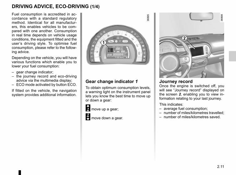
2.11
Fuel consumption is accredited in ac-cordance with a standard regulatory method. Identical for all manufactur-ers, this enables vehicles to be com-pared with one another. Consumption in real time depends on vehicle usage conditions, the equipment fitted and the user’s driving style. To optimise fuel consumption, please refer to the follow-ing advice.Depending on the vehicle, you will have various functions which enable you to lower your fuel consumption:– gear change indicator;– the journey record and eco-driving
advice via the multimedia display;– ECO mode activated by button ECO.If fitted on the vehicle, the navigation system provides additional information.
12
Journey recordOnce the engine is switched off, you will see “Journey record” displayed on the screen 2, enabling you to view in-formation relating to your last journey.This indicates: – average fuel consumption;– number of miles/kilometres travelled;– number of miles/kilometres saved.
DRIVING ADVICE, ECO-DRIVING (1/4)
Gear change indicator 1To obtain optimum consumption levels, a warning light on the instrument panel lets you know the best time to move up or down a gear:
Š move up a gear;
‰ move down a gear.

2.12
Mode ECOECO mode is a function which opti-mises fuel consumption. It acts on all elements which consume fuel (engine power, heating and/or air conditioning, etc).
Activating the functionPress the switch 3.
The warning light comes on on the instrument panel to confirm activa-tion.While driving, it is possible to leave the ECO mode temporarily in order to im-prove engine performance.To do this, press the accelerator pedal firmly and fully. ECO mode is reactivated when you take pressure off the accelerator pedal.
Disabling the functionPress the switch 3.
The warning light goes out on the instrument panel to confirm deac-tivation.
3
DRIVING ADVICE, ECO-DRIVING (2/4)An overall rating from 0 to 100 is dis-played to let you assess your eco driv-ing performance. The higher the score, the better your eco-driving perform-ance.Eco advice is given to help improve your performance.With your favourite journeys saved, you can evaluate your performance.For more information, please see the multimedia system instructions.

2.13
Driving advice and ECO drivingBehaviour– Drive carefully for the first few miles
until the engine reaches its normal operating temperature, rather than let it warm up while the vehicle is sta-tionary.
– Speed is expensive.– Sporty driving uses a lot of fuel: drive
with a light right foot.– Do not overrev the engine in the in-
termediate gears. You should always use the highest
gear possible.
Obstructions to the driverOn the driver’s side, only use mats suitable for the vehicle, attached with the
pre-fitted components, and check the fitting regularly. Do not lay one mat on top of another.There is a risk of wedging the pedals
DRIVING ADVICE, ECO-DRIVING (3/4)– Avoid sudden acceleration.– Brake as little as possible. If you an-
ticipate an obstacle or bend in ad-vance, you may then simply release the accelerator pedal.
– Do not try to maintain the same speed up a hill, accelerate no more than you would on the level. Keep your foot in the same position on the accelerator pedal.
– Double declutching and accelerating before switching off are unnecessary in modern vehicles.
– Bad weather, flooded roads:
Do not drive through floods if the water is above the lower edge of the wheel rims.

2.14
DRIVING ADVICE, ECO-DRIVING (4/4)
Advice on use– Favour the ECO mode.– Electricity is fuel; switch off all the
electrical components which are not really needed. However (safety first), keep your lights on when the visibility is bad (“see and be seen”).
– Use the air vents. Driving with the windows open at 60 mph (100 km/h) will increase fuel consumption by 4%.
– Never fill the fuel tank right to the brim to avoid overflow.
– In vehicles fitted with air condi-tioning, it is normal to observe an increase in fuel consumption (es-pecially in urban conditions) when it is used. For vehicles fitted with manual air conditioning, switch off the system when it is not required.Advice for reducing consumption and therefore helping to preserve the environment:If the vehicle has been parked in the sun, open the doors for a few mo-ments to let the hot air escape before starting the engine.
– Do not leave an empty roof rack fitted to the vehicle.
– Avoid using the car for door-to-door calls (short journeys with long waits in between) because the engine never reaches its normal operating temperature.
Tyres– An underinflated tyre increases fuel
consumption.– The use of non-recommended tyres
can increase fuel consumption.

2.15
MAINTENANCE AND ANTIPOLLUTION ADVICE Your vehicle complies with criteria for recycling and recovering vehicles at the end of their service life which will come into force in 2015.Some parts of your vehicle have there-fore been designed to facilitate future recycling.These parts are easy to remove so that they can be recovered and reproc-essed by recycling companies.By virtue of its design, moderate fuel consumption and initial settings, your vehicle also conforms to current anti-pollution regulations. The manufac-turer is actively striving to reduce pol-lutant exhaust gas emissions and to save energy. But the fuel consumption of your vehicle and the level of pollutant exhaust gas emissions are also your responsibility. Ensure that it is main-tained and used correctly.
MaintenanceIt is important to remember that fail-ure to respect anti-pollution regulations could lead to legal action being taken against the vehicle owner.
In addition, replacing engine, fuel supply system and exhaust compo-nents with parts other than those origi-nally recommended by the manufac-turer may alter your vehicle so that it no longer complies with anti-pollution regulations.Have your vehicle adjusted and checked by an authorised dealer, in ac-cordance with the instructions given in your maintenance schedule: they will have all the equipment necessary for ensuring that your vehicle is maintained to its original standard.
Engine adjustments– Spark plugs: for optimum condi-
tions of use, output and performance the specifications laid down by our Design Department must be strictly applied.
If the spark plugs have to be changed, use the make, type and gap specified for your vehicle’s engine. Contact an authorised dealer for this.
– Air filter, fuel filter: a choked ele-ment will reduce efficiency. It must be replaced.
– Ignition and idle speed: no adjust-ment is needed.
Exhaust gas monitoring systemThe exhaust gas monitoring system will detect any operating faults in the vehi-cle’s antipollution system.If this system malfunctions, toxic sub-stances may be released into the at-mosphere or damage may occur.
Ä This warning light on the in-strument panel will indicate if
there are any faults in the system:This lights up when the ignition is switched on and goes out when the engine is started.– If it lights up continuously, consult an
approved Dealer as soon as possi-ble;
– if it flashes, reduce the engine speed until the light stops flashing. Contact an authorised dealer as soon as pos-sible.

2.16
ENVIRONMENTYour vehicle has been designed with respect for the environment in mind for its entire service life: during production, use and at the end of its life.This commitment is illustrated by the of the manufacturer eco² signature.
ManufactureYour vehicle has been manufactured at a factory which complies with a policy to reduce the environmental impact on the surrounding areas (reduction of water and energy consumption, visual and noise pollution, atmospheric emis-sions and waste water; sorting and re-using waste).
EmissionsIn usage phase, your vehicle was de-signed to emit fewer greenhouse gases (CO2) and therefore consume less fuel.Our vehicles are also equipped with a particle filter system including a cata-lytic converter, an oxygen sensor and an active carbon filter (the latter pre-vents vapour from the fuel tank being released into the open air).
Please make your own contribution towards protecting the environment too– Worn parts replaced in the course of
routine vehicle maintenance (vehi-cle battery, oil filter, air filter, batter-ies, etc.) and oil containers (empty or filled with used oil) must be disposed of through specialist organisations.
– At the end of the vehicle’s service life, it should be sent to approved centres to ensure that it is recycled.
– In all cases, comply with local legis-lation.
RecyclingYour vehicle is 85% recyclable and 95% recoverable.To achieve these objectives, many of the vehicle components have been de-signed to enable them to be recycled. The materials and structures have been carefully designed to allow these components to be easily removed and reprocessed by specialist companies.In order to preserve raw material re-sources, this vehicle incorporates nu-merous parts made from recycled plas-tics or renewable materials (vegetable or animal-derived materials such as cotton or wool).
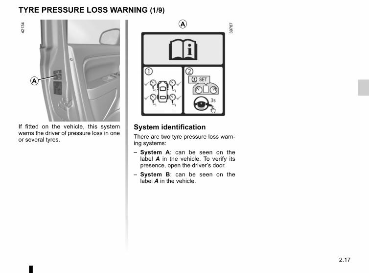
2.17
TYRE PRESSURE LOSS WARNING (1/9)
If fitted on the vehicle, this system warns the driver of pressure loss in one or several tyres.
A
System identificationThere are two tyre pressure loss warn-ing systems:– System A: can be seen on the
label A in the vehicle. To verify its presence, open the driver’s door.
– System B: can be seen on the label A in the vehicle.
A

2.18
TYRE PRESSURE LOSS WARNING (2/9)
1
SYSTEM AOperating principleThis system detects a loss of pressure in one of the tyres by measuring the wheel speed while driving.
Warning light 1 comes on to alert the driver in the event of insuffi-cient pressure (deflated wheel, punctu-red tyre, etc.).
Operating conditionsThe system should be reset with an inflation pressure equal to that given on the tyre inflation pressure label. Otherwise it risks not giving a reliable warning in the event of a significant loss of pressure. Please refer to the informa-tion on “Tyre pressures” in Section 4.In the following situations, the system risk coming into action late or not func-tioning correctly:– system not reset after reinflation or
any operation on the wheels;– system badly reset: different inflation
pressures from the recommended pressures;
– significant change in load or distribu-tion of load on one side of the vehi-cle;
– sporty driving with strong accelera-tion;
– driving on snowy or slippery surface;
– driving with snow chains;– fitting a single new tyre;– use of tyres not approved by the net-
work.– ...
This function is an addi-tional driving aid.The function does not take the place of the driver. It
cannot, therefore, under any cir-cumstances replace the vigilance or the responsibility of the driver.Check the tyre pressures, including the emergency spare wheel, once a month.
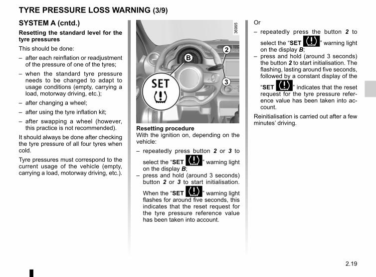
2.19
TYRE PRESSURE LOSS WARNING (3/9)
SYSTEM A (cntd.)Resetting the standard level for the tyre pressuresThis should be done:– after each reinflation or readjustment
of the pressure of one of the tyres;– when the standard tyre pressure
needs to be changed to adapt to usage conditions (empty, carrying a load, motorway driving, etc.);
– after changing a wheel;– after using the tyre inflation kit;– after swapping a wheel (however,
this practice is not recommended).It should always be done after checking the tyre pressure of all four tyres when cold.Tyre pressures must correspond to the current usage of the vehicle (empty, carrying a load, motorway driving, etc.).
2
3
Resetting procedureWith the ignition on, depending on the vehicle:– repeatedly press button 2 or 3 to
select the “SET ” warning light on the display B;
– press and hold (around 3 seconds) button 2 or 3 to start initialisation.
When the “SET ” warning light flashes for around five seconds, this indicates that the reset request for the tyre pressure reference value has been taken into account.
Or– repeatedly press the button 2 to
select the “SET ” warning light on the display B;
– press and hold (around 3 seconds) the button 2 to start initialisation. The flashing, lasting around five seconds, followed by a constant display of the
“SET ” indicates that the reset request for the tyre pressure refer-ence value has been taken into ac-count.
Reinitialisation is carried out after a few minutes’ driving.
B

2.20
System unavailable
Warning light 1 flashes for sev-eral seconds, then stays on.
TYRE PRESSURE LOSS WARNING (4/9)
The sudden loss of pressure in a tyre (burst tyre, etc.) cannot be de-tected by the system.
SYSTEM A (cntd.)Inflate tyres and reset
The 1 warning light comes on (not flashing).This indicates that at least one tyre is flat or punctured.In the event of a flat tyre, inflate the re-levant tyre.In the event of a puncture, change the tyre or consult an authorised dealer.Check and readjust the pressure of the four tyres when cold, and launch the reinitialisation of the tyre pressure refe-rence value.
Warning light 1 goes out after launching the reset of the tyre pressure reference value.System to be checked
Warning light 1 flashes for sev-eral seconds, then stays on. This warn-ing light appears along with the © warning light.They indicate a system fault. Please consult an authorised dealer.
1

2.21
TYRE PRESSURE LOSS WARNING (5/9)
SYSTEM A (cntd.)Readjustment of tyre pressuresThe tyre pressures must be adjusted when cold (please refer to the label lo-cated on the edge of the driver’s door).If tyre pressures cannot be checked when the tyres are cold, the recom-mended pressures should be increased by 0.2 to 0.3 bar (3 PSI).Never deflate a hot tyre.After each reinflation or readjustment of the tyre pressure, launch the reinitiali-sation of the tyre pressure reference value.
Replacing wheels/tyresOnly use equipment approved by the brand network, or the system risks being activated late or not operating correctly. Please see the information on “Tyres” in Section 5.After each change of wheel/tyre, read-just the tyre pressure and launch the reinitialisation of the tyre pressure ref-erence value.
Tyre repair product and inflation kitOnly use equipment approved by the brand network, or the system risks being activated late or not operating correctly. Please refer to “Tyre inflation kit” in Section 5.After using the tyre inflation kit, readjust the tyre pressure and launch the reini-tialisation of the tyre pressure reference value.

2.22
TYRE PRESSURE LOSS WARNING (6/9)
SYSTEM BOperating principleEach wheel (except for the emergency spare wheel) has a sensor in the infla-tion valve which periodically measures the tyre pressure while driving.
Warning light 1 comes on to alert the driver in the event of insuffi-cient pressure (deflated wheel, punctu-red tyre, etc.).
1
Resetting the standard level for the tyre pressuresThis should be done:– when the standard tyre pressure
needs to be changed to adapt to usage conditions (empty, carrying a load, motorway driving, etc.);
– after swapping a wheel (however this practice is not recommended);
– after changing a wheel.It should always be done after checking the tyre pressure of all four tyres when cold.Tyre pressures must correspond to the current usage of the vehicle (empty, carrying a load, motorway driving, etc.).
This function is an addi-tional driving aid.The function does not take the place of the driver. It
cannot, therefore, under any cir-cumstances replace the vigilance or the responsibility of the driver.Check the tyre pressures, including the emergency spare wheel, once a month.

2.23
TYRE PRESSURE LOSS WARNING (7/9)
SYSTEM B (cntd.)Resetting procedureWith the ignition on, depending on the
vehicle:– repeatedly press button 2 or 3 to
select the “SET ” warning light on the display B;
– press and hold (around 3 seconds) button 2 or 3 to start initialisation.
When the “SET” warning light flashes for around five seconds, this indicates that the reset request for the tyre pres-sure reference value has been taken into account.Reinitialisation is carried out after a few minutes’ driving.Note: the standard tyre pressure cannot be less than that recommended and indicated on the door frame.Or– repeatedly press the button 2 to
select the “SET ” warning light on the display B;
– press and hold (around 3 seconds) the button 2 to start initialisation. The flashing, lasting around five seconds, followed by a constant display of the
“SET ” indicates that the reset request for the tyre pressure refer-ence value has been taken into ac-count.
2
3
B
Reinitialisation is carried out after a few minutes’ driving.

2.24
TYRE PRESSURE LOSS WARNING (8/9)
SYSTEM B (cntd.)Inflate tyres
The 1 warning light comes on (not flashing).This indicates that at least one tyre is flat.Check and, if necessary, readjust the pressures of the four wheels when cold.
The warning light 1 goes off after a few minutes’ driving.
The sudden loss of pressure in a tyre (burst tyre, etc.) cannot be de-tected by the system.
Puncture
Warning light 1 comes on steady, accompanied by a beep and warning light ®.They indicate that at least one wheel is punctured or severely underinfla-ted. Replace it or contact an authorised dealer if it is punctured. Top up the tyre pressure if the wheel is deflated.
Warning light ® re-quires you to stop immedi-ately, for your own safety, as soon as traffic conditions
allow.
Check tyre sensors
The warning light 1 flashes for several seconds, then stays on, along with the warning light ©.These indicate that at least one of the sensors is defective or missing. In other cases, contact an authorised dealer.
1

2.25
SYSTEM B (cntd.)Readjustment of tyre pressuresThe tyre pressures must be adjusted when cold (please refer to the label lo-cated on the edge of the driver’s door).If tyre pressures cannot be checked when the tyres are cold, the recom-mended pressures must be increased by 0.2 to 0.3 bar (3 PSI).Never deflate a hot tyre.
TYRE PRESSURE LOSS WARNING (9/9)Replacing wheels/tyresThis system requires specific equip-ment (wheels, tyres, hubcaps, etc.). Please see the information on “Tyres” in Section 5.Contact an approved Dealer to fit new tyres and to find out about available ac-cessories compatible with the system and available from your dealer net-work: the use of any other accessory could affect the correct operation of the system or damage a sensor.
Emergency spare wheelIf the vehicle is equipped with an emer- -gency spare wheel, it will not have a sensor. When it is fitted on the vehicle,
the warning light flashes for sev-eral seconds, then stays on, together with the warning light ©.
Tyre repair product and inflation kitBecause the valves are specially desi-gned, only use equipment approved by the approved network. Please refer to “Tyre inflation kit” in Section 5.

2.26
Depending on the vehicle, this is com-posed of:– anti-lock braking system (ABS);– electronic stability control (ESC)
with understeer control, traction control and assistance with side winds;
– emergency brake assist;– hill start assistance.
Operating faults:
– © and x come on on the instrument panel: ABS, ESC and emergency brake assist are deacti-vated. Braking is always enabled;
– x, D, © and ® come on on the instrument panel: this indicates a fault in the brak-ing system.
In both cases, consult an approved Dealer.
Anti-lock braking system (ABS)Under heavy braking, the ABS prevents the wheels from locking, allowing the stopping distance to be managed and keeping control of the vehicle.Under these circumstances, the vehi-cle can be steered to avoid an obstacle whilst braking. In addition, this system can increase stopping distances, par-ticularly on roads with low surface grip (wet ground etc.).You will feel a pulsation through the brake pedal each time the system is activated. The ABS does not in any way improve the vehicle's physical per-formance relating to the road surface and road-holding. It is still essential to follow the rules of good driving practice (such as driving at a safe distance from the vehicle in front etc.).
DRIVER CORRECTION DEVICES AND AIDS (1/4)
These functions are an ad-ditional aid in the event of critical driving conditions, enabling the vehicle behav-
iour to be adapted to suit the driving conditions.The functions do not take the place of the driver. They do not increase the vehicle’s limits and should not encourage you to drive more quickly. Therefore, they can under no circumstances replace the vigi-lance or responsibility of the driver when manoeuvring the vehicle (the driver must always be ready for sudden incidents which may occur when driving).
In an emergency, apply firm and continuous pressure to the brake pedal. There is no need to pump it repeatedly. The ABS will modu-late the force applied in the braking system.
Your braking systems are partially operational. However, it is dangerous to brake suddenly and
it is essential to stop immediately, as soon as traffic conditions allow. Contact an approved dealer.

2.27
Electronic stability control (ESC) with understeer control, traction control and assistance with side windsElectronic stability control ESCThis system helps you to keep control of the vehicle in critical driving condi-tions (avoiding an obstacle, loss of grip on a bend, etc.).A sensor in the steering wheel detects the direction selected by the driver.Other sensors throughout the vehicle measure the actual direction.The system compares driver input to the actual trajectory of the vehicle and corrects the trajectory if necessary by controlling the braking of certain wheels and/or engine power. In the event that the system is engaged, indicator light
flashes on the instrument panel.
DRIVER CORRECTION DEVICES AND AIDS (2/4)Understeer controlThis system optimises the action of the ESC in the case of pronounced under-steer (loss of front axle road holding).
Assistance with side windsThis system optimises the action of the ESC and also helps to control the vehi-cle in case of variation of side winds. It helps maintain the vehicle trajectory through the use of the brakes.If the system is activated, the indicator
light may flash on the instrument panel.
Traction controlThis system helps to limit wheelspin of the drive wheels and to control the ve-hicle when pulling away accelerating or decelerating.Using the wheel sensors, the system measures and compares the speed of the drive wheels at all times and slows down their over-rotation. If a wheel is starting to slip, the system brakes au-tomatically until the drive supplied be-comes compatible with the level of grip under the wheel again.
The system also adjusts the engine speed to the grip available under the wheels, independently of the pressure exerted on the accelerator pedal.
Operating faultsWhen the system detects an operat-ing fault the warning lights © and
appear on the instrument panel. In this case, the ESC and traction con-trol system are deactivated. Consult an approved dealer.

2.28
DRIVER CORRECTION DEVICES AND AIDS (3/4) Emergency brake assistThis system supplements the ABS and helps reduce vehicle stopping dis-tances.The system allows an emergency brak-ing situation to be detected when the brake pedal is pressed. In this case, the braking assistance immediately devel-ops maximum power and may trigger ABS regulation.ABS braking is maintained as long as the brake pedal is applied.
Hazard warning lights switching onDepending on the vehicle, these may light up in the event of sudden decel-eration.
Braking anticipationDepending on the vehicle, when you rapidly release the accelerator, the system anticipates the braking ma-noeuvre in order to reduce stopping distances.When using the cruise control:– if you use the accelerator, when you
release it, the system may be trig-gered;
– if you do not use the accelerator, the system will not be triggered.
Operating faultsWhen the system detects an operating fault, the warning light © comes on on the instrument panel.Consult an approved dealer.
These functions are an ad-ditional aid in the event of critical driving conditions, enabling the vehicle behav-
iour to be adapted to suit the driving conditions.The functions do not take the place of the driver. They do not increase the vehicle’s limits and should not encourage you to drive more quickly. Therefore, they can under no circumstances replace the vigi-lance or responsibility of the driver when manoeuvring the vehicle (the driver must always be ready for sudden incidents which may occur when driving).

2.29
DRIVER CORRECTION DEVICES AND AIDS (4/4)
Hill start assistanceDepending on the gradient of the in-cline, this system assists the driver when starting on a hill. It prevents the vehicle from rolling backwards, de-pending on the slope, by automatically applying the brakes when the driver lifts his/her foot off the brake pedal to de-press the accelerator pedal.It only operates when the gear lever is in a position other than neutral (other than N or P for automatic transmis-sions) and the vehicle is completely stationary (brake pedal depressed)The system holds the vehicle for ap-proximately 2 seconds. The brakes are then gradually released (the vehicle will move according to the slope).
The hill start assistance system cannot completely prevent the vehicle from rolling backwards in all sit-
uations (extremely steep gradients etc.).In all cases, the driver may depress the brake pedal to prevent the vehi-cle from rolling backwards.The hill start assistance function should not be used for prolonged stops: use the brake pedal.This function is not designed to im-mobilise the vehicle permanently.If necessary, use the brake pedal to stop the vehicle.The driver must remain particularly vigilant when driving on slippery or low-grip surfaces.Risk of serious injury.

2.30
LANE DEPARTURE WARNING (1/2)This lane departure warning system no-tifies the driver when they accidentally cross a continuous or broken line.This function uses a camera attached to the windscreen, behind the rear-view mirror.
This function is a driving aid in the event of the accidental crossing of a continuous or broken line in the road. However, the function is not in-tended to replace the driver. The function can be disrupted under certain conditions, including:
– poor visibility (rain, snow, fog, dirty windscreen, glare of the sun, partially obs-cured road lines, etc.);
– roads with tight bends;– closely following a vehicle in the same lane;– worn road markings, difficult to distinguish or spaced very widely apart;– narrow roads;– ...
In this case, warning light on the instrument panel goes out to indicate that the function will not operate (lines not detected).Under no circumstances should this function replace the driver’s care or res-ponsibility whilst performing manoeuvres.

2.31
LANE DEPARTURE WARNING (2/2)
DeactivationPress the switch 1. The warning light 2 in the switch 1 goes out.
Operating faultsIn the event of a malfunction, the warn-ing light on the button 1 remains off,
and warning lights © and come on on the instrument panel along-side a beep. Please consult an autho-rised dealer.
When a line is crossed and the indica-tors have not been activated, the func-tion alerts the driver through warning
light on the instrument panel, and a beep.
Conditions for non-activation of alerts– Indicators activated or having been
activated less than approximately four seconds prior to departing from the lane;
– Very fast lane departure;– Driving continuously on a line;– On bends, the function allows for
slightly cutting the bend;– dirt covering the windscreen camera;– ...
ActivationPress the switch 1: the warning light 2 integrated on the switch 1 comes on.The function sounds the alarm if:– the warning light lighted integrated
on the switch 1 is on;and– the vehicle speed is greater than ap-
proximately 45 mph (70 km/h);and– lines are detected.
Warning light comes on on the instrument panel to notify the driver.
1
2

2.32
Switching onPress the side switch 1 . Indicator light 6 comes on, lit orange, and the message “LIMIT” appears on the instru-ment panel, accompanied by dashes to indicate that the speed limiter function is activated and waiting to store a lim-ited speed. To store the current speed, press switch 2 (+): the limited speed will re-place the dashes.The minimum stored speed is 20 mph (30 km/h).
Controls1 Main “On/Off” switch.2 Limit speed activation, storage and
increase switch (+).3 Decreasing the limit speed (-).4 Activation and recall of memorised
limit speed (R).5 Speed limiter function standby (with
limited speed memory) (O).
The speed limiter function helps you stay within the driving speed limit that you choose, known as the limit speed.
SPEED LIMITER (1/3)
2 3 54
6
1

2.33
Exceeding the limit speedIt is possible to exceed the limit speed at any time. To do this: press the accel-erator pedal firmly and fully (beyond the resistance point).While the speed is being exceeded, the limit speed displayed on the instrument panel flashes.Then, release the accelerator: the speed limiter function will return as soon as you reach a speed lower than the stored speed.
Limited speed cannot be maintainedIf driving up or down a steep gradient, the system is unable to maintain the limited speed: the memorised speed flashes on the instrument panel and a beep sounds at regular intervals to inform you.
Varying the limit speedThe limit speed may be changed by re-peatedly pressing:– switch 2 (+) to increase speed;– switch 3 (-) to reduce speed.
DrivingWhen a limited speed has been stored and this speed is not reached, driving is similar to driving a vehicle without the speed limiter function.Once you have reached the stored speed, no effort on the accelera-tor pedal will allow you to exceed the programmed speed except in an emergency (refer to information on “Exceeding the limit speed”).
SPEED LIMITER (2/3)
The speed limiter function is in no way linked to the brak-ing system.
2 3

2.34
SPEED LIMITER (3/3)
Recalling the limit speedIf a speed has been saved, it can be re-called by pressing switch 4 ((R)).
Putting the function on standbyThe speed limiter function is suspended when you press switch 5 (O). In this case, the limit speed remains stored and the message “MEM” accompanied by this speed appears on the instru-ment panel.
Switching off the functionThe speed limiter function is deac-tivated if you press switch 1: in this case a speed is no longer stored. The orange instrument panel warning light goes out, confirming that the func-tion is stopped.
When the speed limiter is put on standby, pressing switch 2 (+) re-activates the function without taking into account the stored speed: it is the speed at which the vehicle is moving that is taken into account.
2 3 54
1

2.35
The cruise control function helps you to maintain your driving speed at a speed that you choose, called the cruising speed.This cruising speed may be set at any speed above 20 mph (30 km/h).
This function is an addi-tional driving aid. It does not take the place of the driver.Therefore, it can under no
circumstances replace the driver’s responsibility to respect speed limits and to be vigilant (the driver must always be ready to brake).Cruise control must not be used in heavy traffic, on undulating or slip-pery roads (black ice, aquaplan-ing, gravel) and during bad weather (fog, rain, side winds etc.).There is a risk of accidents.
The cruise control function is in no way linked to the braking system.
Controls1 Main “On/Off” switch.2 Cruising speed activation, storage
and increase switch (+).3 Decreasing cruising speed (-).4 Activation with recall of saved cruis-
ing speed (R).5 Switch the function to standby (with
cruising speed saved) (O).
CRUISE CONTROL (1/4)
2 3 54
1

2.36
DrivingOnce a cruising speed is memorised and the cruise control function is active, you may lift your foot off the accelera-tor pedal.
Please note that you must keep your feet close to the pedals in order to react in an emergency.
Activating cruise controlAt a steady speed (above 18 mph (30 km/h approximately)) press switch 2 or (+): the function is activated and the current speed is saved.The cruising speed replaces the dashes and the cruise control is confirmed by the appearance of warning light 6 lit green, as well as warning light 7.
Switching onPress switch 1 side .Indicator light 7 comes on, lit green, and the message “CRUISE” appears on the instrument panel, accompanied by dashes to indicate that the cruise control function is activated and waiting to store a cruising speed.
CRUISE CONTROL (2/4)
2 3
6 7
1

2.37
CRUISE CONTROL (3/4)
Exceeding the cruising speedThe cruising speed may be exceeded at any time by depressing the accelera-tor pedal. While it is being exceeded, the cruising speed flashes on the in-strument panel.Then, release the accelerator: after a few seconds, the vehicle will automati-cally return to its set cruising speed.
Cruising speed cannot be maintainedWhen driving down a steep gradient, the system is unable to maintain the cruising speed: the stored speed will flash on the instrument panel informa-tion display to inform you of this situ-ation.
Adjusting the cruising speedThe cruising speed may be changed by pressing the following repeatedly:– switch 2 (+) to increase the speed,– switch 3 (-) to decrease the speed.
The cruise control function is in no way linked to the braking system.
2 3

2.38
Switching off the functionThe cruise control function is deacti-vated if you press switch 1: in this case a speed is no longer stored. The two in-strument panel warning lights and go out to confirm that the function is deactivated.
Returning to the cruising speedIf a speed is stored, it can be recalled, once you are sure that the road con-ditions are suitable (traffic, road sur-face, weather conditions, etc.). Press switch 4 (R) if the vehicle speed is above 20 mph (30 km/h).When the stored speed is recalled, acti-vation of the cruise control is confirmed by the illumination of the warning light.NB: if the speed previously stored is much higher than the current speed, the vehicle will accelerate more rapidly to reach this threshold.
When the cruise control function is put on standby, pressing switch 2 (+) reactivates the cruise control function without taking into account the stored speed: it is the speed at which the vehicle is moving that is taken into account.
Putting the function on standbyThe function is set to standby if you:– use the switch 5 (O);– the brake pedal;– depress the clutch pedal or the shift
into neutral if the vehicle has an au-tomatic gearbox.
In all three cases, the cruising speed re-mains stored and the message “MEM” appears on the instrument panel.Standby is confirmed when indicator light goes out.
CRUISE CONTROL (4/4)
Putting the cruise control on standby or switching it off does not cause a rapid reduction in speed: you
must brake by depressing the brake pedal.
2 3 54
1

2.39
Operating principleUltrasonic detectors, installed in the rear bumper (depending on the vehi-cle), measure the distance between the vehicle and an obstacle whilst re-versing.This measurement is indicated by beeps which become more frequent the closer you come to the obstacle, until they become a continuous beep when the vehicle is approximately 30 centi-metres from the obstacle.NB: make sure that the ultrasonic sen-sors are not obscured (by dirt, mud, snow, etc.).
PARKING DISTANCE CONTROL (1/2)
OperationWhen reverse gear is selected, most objects which are less than approxi-mately 1.20 metres from the rear of the vehicle are detected, a beep sounds and, depending on the vehicle, the dis-play 1 comes on.
This function is an additional aid that indicates the distance between the vehicle and an obstacle whilst reversing, using sound signals.Under no circumstances should it replace the driver’s care or responsibility whilst reversing.
The driver should always look out for sudden hazards during driving: always ensure that there are no moving obstacles (such as a child, animal, pram or bicycle, etc.) or small, narrow objects such as stones or posts in your path when manoeuvring.
1

2.40
Deactivating the systemPress switch 2 to deactivate the system:The indicator light built into the switch lights up to remind you that the system is deactivated.Pressing the switch again will reacti-vate the system and switch off the in-dicator light.Depending on the vehicle, you can deactivate the parking distance control from the touch-screen. Please see the equipment instructions for further infor-mation.
2
An impact to the under-side of the vehicle while manoeuvring (e.g.: stri-king a post, raised kerb or
other street furniture) may result in damage to the vehicle (e.g.: defor-mation of an axle).To avoid any risk of accident, have your vehicle checked by an appro-ved Dealer.
PARKING DISTANCE CONTROL (2/2)

2.41
REVERSING CAMERA (1/2)
2
1
Note:– ensure that the reversing camera is
not obscured (dirt, mud, snow, etc.);– depending on the vehicle, certain
settings can be adjusted from the touch screen 2. Refer to the hand-book for the equipment.
OperationWhen going into reverse gear (and up to around 5 seconds after shifting into another gear), the camera 1 placed next to the lights transmits a view of the rear surroundings of the vehicle on the touch screen 2, accompanied by a mobile and fixed gauge.This system is initially used with the aid of several gauges (mobile for trajectory and fixed for distance). When the red zone is reached, use the bumper image to stop accurately.
This function is an additio-nal aid. It cannot, therefore, under any circumstances replace the vigilance or the
responsibility of the driver.The driver should always pay at-tention to sudden incidents during driving: always ensure that there are no moving obstacles (such as a child, animal, pram, bicycle, etc.) or small, narrow objects such as stones or posts in your path when manoeuvring.

2.42
REVERSING CAMERA (2/2)
This function is an additio-nal aid. It cannot, therefore, under any circumstances replace the vigilance or the
responsibility of the driver.The driver should always pay at-tention to sudden incidents during driving: always ensure that there are no moving obstacles (such as a child, animal, pram, bicycle, etc.) or small, narrow objects such as stones or posts in your path when manoeuvring.
C
B
A
Dynamic gauge 3 (depending on the vehicle)This is shown in blue on screen 2. It in-dicates the vehicle trajectory according to the position of the steering wheel.
Static guide line 4:The fixed clearance gauge comprises coloured markers A, B and C, indicat-ing the distance behind the vehicle:– A (red) approximately 30 centi-
metres from the vehicle;– B (yellow) approximately 70 centi-
metres from the vehicle;– C (green) approximately 150 centi-
metres from the vehicle.
43
The screen shows a reverse image.The frames are a representation projected onto flat ground; this information must not be taken into account when superimposed on a vertical object or an object on the ground.Objects which appear on the edge of the screen may be deformed.In very bright light (snow, vehicle in sunshine etc.), the camera vision may be
adversely affected. If the boot is open or poorly closed, the warning light 2 ap-pears on the instrument panel and, depending on the vehicle, the camera display disappears.
2
This gauge remains fixed and indicates the vehicle trajectory if the wheels are in line with the vehicle.

2.43
AUTOMATIC TRANSMISSION (1/4)
OperationWith gear lever 1 in position P, start the engine.To move out of that position, you must depress the brake pedal (the c warn-ing light on the display 4 comes on) before pressing the unlocking button 2.With your foot on the brake pedal (warning light c in display 4 goes out), move the lever out of position P.
2
1
Selector lever 1P: parkR: reverseN: neutralD: automatic modeM: manual mode3: zone displaying gearbox mode or
gear engaged in manual modeNote: press button 2 to go from position D or N to R or P.
43
Only engage D or R when the vehi-cle is stopped, with your foot on the brake and the accelerator pedal re-leased.

2.44
AUTOMATIC TRANSMISSION (2/4)
Driving in manual modeWith the selector lever in position D, move the lever to the left. Shifting the lever repeatedly allows you to change gears manually:– To move down through the gears,
push the lever backwards;– To move up through the gears, push
the lever forwards.The gear selected is displayed on the instrument panel.
Special casesUnder certain driving conditions (e.g. engine protection, electronic stability program (ESP) operational etc.: ESC)) the automatic system may change the gear automatically.Likewise, to prevent incorrect manoeu-vres, a gear change may be refused by the automatic system: in this case the gear display flashes for a few seconds as a warning.
Driving in automatic modeSelect position D. In most traffic con-ditions, you will not have to touch the gear selector lever again: the gears will change automatically at the right time and at the most suitable engine speed because the automatic system takes into account the vehicle load and road contour and adjusts itself to the particu-lar driving style you have chosen.
Economical drivingWhen driving, always leave the lever in position D, keeping the accelerator pedal lightly depressed to ensure auto-matic gear changes at a lower engine speed.
Accelerating and overtakingDepress the accelerator pedal firmly and fully (so that it goes beyond the kickdown point).This will enable you to change down to the optimum gear within the engine range.

2.45
Special circumstances– If the road contours and bends
do not allow you to stay in auto-matic mode (e.g.: in the mountains), we recommend that you change to manual mode.This will prevent the automatic gear-box from changing gears repeatedly when climbing, and permit engine braking on long descents.
– In cold weather, to prevent the engine from stalling, wait a few mo-ments before shifting the selector lever from position P or N and en-gaging D or R.
In very cold weather, the system may prevent the gears from being shifted in manual mode until the gearbox reaches the right tempera-ture.
Parking the vehicleWhen the vehicle is stopped, move the lever to position P while keeping your foot on the brake pedal: the gearbox is in neutral and the drive wheels are me-chanically locked by the driveshaft.Apply the handbrake.
An impact to the under-side of the vehicle while manoeuvring (e.g.: strik-ing a post, raised kerb or
other street furniture) may result in damage to the vehicle (e.g.: defor-mation of an axle).To avoid any risk of accident, have your vehicle checked by an ap-proved Dealer.
AUTOMATIC TRANSMISSION (3/4)
Maintenance period Refer to the your vehicle maintenance document or consult an Approved Dealer to check whether the automatic gearbox requires scheduled mainte-nance.If it does not need to be serviced, there is no need to top up the oil.

2.46
Breakdown of a vehicle with an automatic gearboxRefer to the information on “Towing” in Section 5.When setting off, if the lever is locked in position P, even though you are de-pressing the brake pedal and pressing the unlocking button 2, the lever can still be released manually.
AUTOMATIC TRANSMISSION (4/4)
Operating faultsWhen three horizontal bars on the dis-play 3 come on accompanied by the warning light © or ®, this in-dicates a gearbox fault. Contact an au-thorised dealer as soon as possible.
To do this, unclip the base of the gear lever 5 starting on the side below the air conditioning controls. Then raise the button 6 and simultaneously press the unlock button 2 on the lever.
For safety reasons, do not switch off the ignition before the vehicle has come to a complete standstill.
5
2
3
66
3
Warning light ® re-quires you to stop immedi-ately, for your own safety, as soon as traffic conditions
allow.

3.1
Section 3: Your comfort
Air Vents . . . . . . . . . . . . . . . . . . . . . . . . . . . . . . . . . . . . . . . . . . . . . . . . . . . . . . . . . . . . . . . . . . . . . . 3.2Manual air conditioning, heating system . . . . . . . . . . . . . . . . . . . . . . . . . . . . . . . . . . . . . . . . . . . . . . 3.4Automatic climate control . . . . . . . . . . . . . . . . . . . . . . . . . . . . . . . . . . . . . . . . . . . . . . . . . . . . . . . . . 3.7Air conditioning: information and advice on use . . . . . . . . . . . . . . . . . . . . . . . . . . . . . . . . . . . . . . . . 3.11Electric windows . . . . . . . . . . . . . . . . . . . . . . . . . . . . . . . . . . . . . . . . . . . . . . . . . . . . . . . . . . . . . . . . 3.13Sunroof . . . . . . . . . . . . . . . . . . . . . . . . . . . . . . . . . . . . . . . . . . . . . . . . . . . . . . . . . . . . . . . . . . . . . . . 3.15Interior lighting . . . . . . . . . . . . . . . . . . . . . . . . . . . . . . . . . . . . . . . . . . . . . . . . . . . . . . . . . . . . . . . . . . 3.16Passenger compartment storage/fittings . . . . . . . . . . . . . . . . . . . . . . . . . . . . . . . . . . . . . . . . . . . . . . 3.17Ashtray, cigarette lighter, accessories socket . . . . . . . . . . . . . . . . . . . . . . . . . . . . . . . . . . . . . . . . . . 3.22Rear headrests . . . . . . . . . . . . . . . . . . . . . . . . . . . . . . . . . . . . . . . . . . . . . . . . . . . . . . . . . . . . . . . . . 3.23Rear bench seat . . . . . . . . . . . . . . . . . . . . . . . . . . . . . . . . . . . . . . . . . . . . . . . . . . . . . . . . . . . . . . . . 3.24Luggage compartment. . . . . . . . . . . . . . . . . . . . . . . . . . . . . . . . . . . . . . . . . . . . . . . . . . . . . . . . . . . . 3.25Luggage cover . . . . . . . . . . . . . . . . . . . . . . . . . . . . . . . . . . . . . . . . . . . . . . . . . . . . . . . . . . . . . . . . . . 3.26Rear parcel shelf . . . . . . . . . . . . . . . . . . . . . . . . . . . . . . . . . . . . . . . . . . . . . . . . . . . . . . . . . . . . . . . . 3.26Boot storage . . . . . . . . . . . . . . . . . . . . . . . . . . . . . . . . . . . . . . . . . . . . . . . . . . . . . . . . . . . . . . . . . . . 3.27Transporting objects in the luggage compartment . . . . . . . . . . . . . . . . . . . . . . . . . . . . . . . . . . . . . . 3.28Roof bars . . . . . . . . . . . . . . . . . . . . . . . . . . . . . . . . . . . . . . . . . . . . . . . . . . . . . . . . . . . . . . . . . . . . . . 3.29Spoiler . . . . . . . . . . . . . . . . . . . . . . . . . . . . . . . . . . . . . . . . . . . . . . . . . . . . . . . . . . . . . . . . . . . . . . . . 3.29Multimedia equipment . . . . . . . . . . . . . . . . . . . . . . . . . . . . . . . . . . . . . . . . . . . . . . . . . . . . . . . . . . . . 3.30

3.2
AIR VENTS, air outlets (1/2)
3
8
5 61 2
7
1 Left-hand side window demister outlet.
2 Left-hand air vent. 3 Windscreen demisting vents. 4 Centre air vents.
5 Right-hand air vent. 6 Right-hand side window demister
outlet. 7 Passenger footwell heater out-
lets. 8 Control panel
7
4

3.3
Side air ventsAir flowTo open air vent 10, press on the air vent (point 11) until it is open as far as required.
DirectionTo direct the air flow, swivel side air vent 10.
Centre air vents.DirectionMove cursors 9 to the required position.
AIR VENTS, air outlets (2/2)
10
11
Do not add anything to the vehicle’s ventilation circuit (for example, to remove bad odours).
There is a risk of damage or of fire.
9
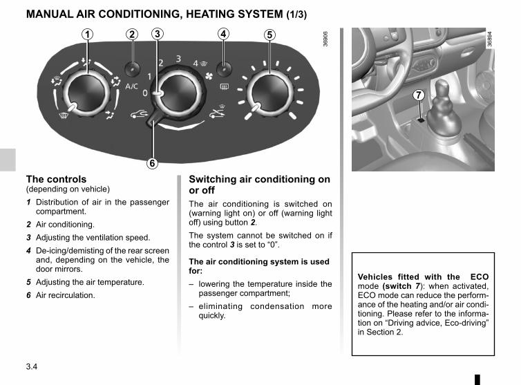
3.4
Switching air conditioning on or offThe air conditioning is switched on (warning light on) or off (warning light off) using button 2.The system cannot be switched on if the control 3 is set to “0”.
The air conditioning system is used for:– lowering the temperature inside the
passenger compartment;– eliminating condensation more
quickly.
The controls(depending on vehicle)1 Distribution of air in the passenger
compartment. 2 Air conditioning. 3 Adjusting the ventilation speed.4 De-icing/demisting of the rear screen
and, depending on the vehicle, the door mirrors.
5 Adjusting the air temperature.6 Air recirculation.
MANUAL AIR CONDITIONING, HEATING SYSTEM (1/3)
531 42
6
7
Vehicles fitted with the ECO mode (switch 7): when activated, ECO mode can reduce the perform-ance of the heating and/or air condi-tioning. Please refer to the informa-tion on “Driving advice, Eco-driving” in Section 2.

3.5
Air recirculation is for:– isolating the vehicle from the exter-
nal atmosphere (driving in polluted areas, etc.).
– to bring the passenger compartment to the desired temperature as quickly as possible.
Switching the air recirculation onPush the control 6 to the left. In these conditions, air is taken from the pas-senger compartment and is recycled, with no air being taken from outside the vehicle.
MANUAL AIR CONDITIONING, HEATING SYSTEM (2/3)
Prolonged use of air recirculation can lead to condensation forming on the side windows and windscreen, and discomfort due to the use of non-renewed air in the passenger compartment.We therefore advise you to return to normal mode (external air) as soon as the air recirculation function is no longer required, by pressing the button 6 again.
531 2 4Distribution of air in the passenger compartmentTurn the control 1 to choose the distri-bution option.
W The air flow is directed to the windscreen and the front side
window demisting vents.
i The air flow is distributed be-tween all the air vents, the
front side window demisting vents, the windscreen demisting vents and the footwells.
ó The air flow is directed mainly towards the footwells.
G The air flow is directed towards the dashboard air vents and
the front footwells.
J All the air flow is directed to the dashboard vents.
6

3.6
Note: the air conditioning is not opera-tional below 2°C.If you want to shut off the flow of air, set the control 3 to “0”. The system is de-activated: the ventilation speed is zero (vehicle stationary). You can, however, still feel a slight flow of air when the ve-hicle is moving.
Adjusting the amount of air blown into the passenger compartmentMove control 3. The further the control is positioned to the right, the greater the amount of air blown into the passenger compartment.
DemistingTo activate demisting, position con-
trols 1 and 3 to position W, and
control 6 to position . If demisting remains incomplete, press button 2 to use the air conditioning.
4
5
MANUAL AIR CONDITIONING, HEATING SYSTEM (3/3)
531 4 Adjusting the air temperatureTurn the control 5 to obtain the desired temperature. The further towards the red the slide is, the higher the tempera-ture will be.When the air conditioning system is used for long periods, it may begin to feel cold. To increase the temperature, turn the control 5 to the right.
Rear screen de-icing/demistingWith the engine running, press button 5. The integrated indicator light comes on.This function permits rapid demisting/de-icing of the rear screen and de-icing of the door mirrors (on equipped vehi-cles).To exit this function, press button 4 again.Demisting automatically stops.
2
6
Prolonged use of position “0” can lead to condensation forming on the side windows and windscreen and problems due to the use of non-re-newed air in the passenger com-partment.
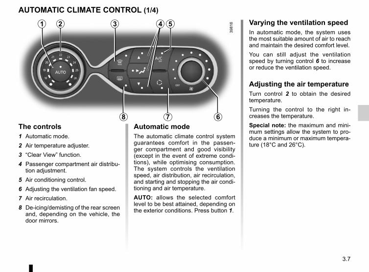
3.7
Varying the ventilation speedIn automatic mode, the system uses the most suitable amount of air to reach and maintain the desired comfort level.You can still adjust the ventilation speed by turning control 6 to increase or reduce the ventilation speed.
Adjusting the air temperatureTurn control 2 to obtain the desired temperature. Turning the control to the right in-creases the temperature.Special note: the maximum and mini-mum settings allow the system to pro-duce a minimum or maximum tempera-ture (18°C and 26°C).
The controls1 Automatic mode.2 Air temperature adjuster.3 “Clear View” function.4 Passenger compartment air distribu-
tion adjustment.5 Air conditioning control.6 Adjusting the ventilation fan speed.7 Air recirculation.8 De-icing/demisting of the rear screen
and, depending on the vehicle, the door mirrors.
AUTOMATIC CLIMATE CONTROL (1/4)
2 3 5
78 6Automatic modeThe automatic climate control system guarantees comfort in the passen-ger compartment and good visibility (except in the event of extreme condi-tions), while optimising consumption. The system controls the ventilation speed, air distribution, air recirculation, and starting and stopping the air condi-tioning and air temperature.AUTO: allows the selected comfort level to be best attained, depending on the exterior conditions. Press button 1.
1 4

3.8
Clear View functionPress button 3 – the integrated indica-tor light comes on.This function quickly demists and de-ices the windscreen, the rear screen, the front side windows, and the door mirrors (depending on the vehicle). The air conditioning and rear screen de-ic-ing functions must be activated.Press button 8 to stop the heated rear screen operating, and the integrated in-dicator goes out.To exit this function, press button 3 or 1.
AUTOMATIC CLIMATE CONTROL (2/4)
Ø The air flow is distributed be-tween all the air vents, the
front side window demisting air vents and the windscreen demisting vents.
½ The air flow is mainly directed to the dashboard air vents.
¿ The air flow is directed mainly towards the footwells.
Adjusting the distribution of air in the passenger compartmentPress one of the buttons 4. The in-tegrated warning light in the button comes on.It is possible to combine two positions simultaneously – press both buttons 4.
8
3
Some buttons have an operating tell-tale which indicates the operat-ing status.
1 4

3.9
Rear screen de-icing/demistingPress button 8 – the integrated indica-tor light comes on. This function en-ables rapid demisting or de-icing of the rear screen and de-icing of the door mirrors (on equipped vehicles).To exit this function, press button 8 again. Demisting automatically stops.
AUTOMATIC CLIMATE CONTROL (3/4)
8Switching air conditioning on or offIn automatic mode, the system switches the air conditioning system on or off, depending on the climate conditions.Press button 5 to switch off the air conditioning; the integrated indicator comes on.
5
Vehicles fitted with the ECO mode (switch 9): once activated, ECO mode can reduce the perform-ance of the automatic air condition-ing. Please refer to the information on “Eco-driving” in Section 2.
9

3.10
AUTOMATIC CLIMATE CONTROL (4/4)
7 6
Air recirculation (isolation of the passenger compartment) KThis function is managed automatically (operation is confirmed by a warning light on button 7), but you can also acti-vate it manually.
NB:– during recirculation, air is taken from
the passenger compartment and is recycled, with no air being taken from outside the vehicle;
– air recirculation allows the external atmosphere to be cut off (when driv-ing in polluted areas, etc.);
– the recirculation of air makes it pos-sible to reach the desired passenger compartment temperature quicker.
1
The demisting/de-icing will still take priority over the air recirculation.
Manual usePress button 7 – the integrated indica-tor light comes on.Prolonged use of this position may lead to odours, caused by non-renewal of air, and the formation of condensation on the windows.We therefore advise you to return to au-tomatic mode as soon as air recircula-tion is no longer needed, by pressing button 7.To exit this function, press button 7 again.
Stopping the systemTurn the control 6 to “OFF” to stop the system. To start it, turn the control 6 again, then adjust the fan speed or press the button 1.

3.11
Operating faultsAs a general rule, contact your ap-proved dealer in the event of an oper-ating fault.– Reduction in de-icing, demisting
or air conditioning performance.This may be caused by the passen-ger compartment filter cartridge be-coming clogged.
– No cold air is being produced.Check that the controls are set cor-rectly and that the fuses are sound. Otherwise, switch off the system.
Presence of water under the vehicleAfter prolonged use of the air condi-tioning system, it is normal for water to be present under the vehicle. This is caused by condensation.
AIR CONDITIONING: information and operating instructions (1/2)
Do not add anything to the vehicle’s ventilation circuit (for example, to remove bad odours).
There is a risk of damage or of fire.
Do not open the refriger-ant fluid circuit. The fluid may damage eyes or skin.
Fuel consumptionYou will normally notice an increase in fuel consumption (especially in town) when the air conditioning is operating.For vehicles fitted with air conditioning with no automatic mode, switch off the system when it is not required.
Advice for reducing consumption and helping to preserve the environmentDrive with the air vents open and the windows closed. If the vehicle has been parked in the sun, open the doors for a few moments to let the hot air escape before starting the engine.
MaintenanceRefer to the Maintenance Document for your vehicle for the inspection fre-quency.
Advice on useIn some situations (air conditioning off, air recirculation activated, ventilation speed at zero or low etc.), you may notice that condensation starts to form on the windows and windscreen.If there is condensation, use the “Clear View” function to remove it, then use the air conditioning in automatic mode to stop it forming again.
Use the air conditioning system reg-ularly, even in cold weather, running it at least once a month for approxi-mately 5 minutes.
Vehicles equipped with mode ECOOnce activated, ECO mode may reduce air conditioning perform-ance. Please refer to the informa-tion on “Driving advice, Eco-driving” in Section 2.

3.12
AIR CONDITIONING: information and operating instructions (2/2)
The refrigerant circuit may contain fluorinated greenhouse gases.Depending on the vehicle, you will find the following information on label A af-fixed inside the engine compartment.The presence and location of the infor-mation on label A depends on the ve-hicle.
Do not open the refriger-ant circuit. The fluid may damage eyes or skin.
Before performing any action in the engine com-partment, the ignition must be switched off (please see
the information on “Starting, stop-ping the engine” in Section 2).
Ñ Type of refrigerant fluid
Type of oil in the air condi-tioning circuit
Inflammable product
Consult the driver’s hand-book
Maintenance
Quantity of refrigerant fluid present in the ve-hicle.
x.xxx kg
Globa l Warming Potential (CO2 equi-valent).
GWP xxxxx
Quantity in weight and in CO2 equivalent.
CO2 eq x.xx t
A A A

3.13
ELECTRIC WINDOWS (1/2)
Press the window switch down or lift it up to lower or raise the window to the desired height.From the driver’s seat, use switch: 1 for the driver’s side; 2 for the front passenger side.From the front passenger seat, move the switch 3.
1
23
One-touch modeDepending on the vehicle, this mode works in addition to the operation of the electric windows described previously. It can be fitted to the driver’s window. Briefly press or pull the switch 1 as far as it will go: the window will wind down or up fully. Pressing the switch again stops the window moving.Note: if the driver’s window detects re-sistance when closing (e.g. tree branch, etc.), it stops and then lowers again by a few centimetres.
Avoid resting any objects against a half-open window: there is a risk that the electric window could be damaged.
These systems operate with the igni-tion on or off, until one of the front doors is opened (limited to about 3 minutes).
Driver’s responsibilityNever leave your vehicle with the key or remote con-trol in it, leaving a child,
adult who is not self-sufficient or a pet inside, even for a short while. They may pose a risk to themselves or to others by starting the engine or activating equipment (such as the gear lever or electric windows). If any part of the body becomes trapped, reverse the direction of the window immediately by pressing the relevant switch.Risk of serious injury.
Closing windows can cause serious injury.

3.14
ELECTRIC WINDOWS (2/2)
4
Manual window windersMove the handle 4 to lower or raise the window to the desired height.
Rear windowsTo half-open the window, turn handle 5 (movement A) then lock it by pushing the handle to the right.Make sure it is properly latched into po-sition when it is closed.
5
A
Operating faultsElectric windowsIn case of a fault when closing a window, the system reverts to normal mode: pull the switch concerned up as often as necessary to fully close the window (the window will close gradually), hold the switch (still on the closure side) for three seconds then lower and raise the window fully to reinitialise the system.If necessary, contact an approved Dealer.
When closing the windows, ensure that no part of the body (arm, hand, etc.) is protruding from the vehicle.
Risk of serious injury.

3.15
SUNROOF
1
– Partial opening: press the switch 1 on side \ until the desired amount of opening.
– Full opening: press the switch 1 on side \ for around 6 seconds.
– To close: press the switch 1 on side [ for around 6 seconds.
Precautions during use– check that the sunroof is properly
closed before leaving your vehicle;– clean the seal every three months
using products recommended by our Technical Department;
– Do not open the sunroof immedi-ately after it has rained or immedi-ately after washing the vehicle.
– vehicle with roof bars:Generally, it is not advisable to oper-ate the sunroof.Before using the sunroof, check the objects and/or accessories (bike racks, roof boxes, etc.) attached to the roof bars: they should be prop-erly arranged and secured and should not interfere with the opera-tion of the sunroof.Contact an authorised dealer for de-tails of possible conversions.
Operating faultsIf the roof will not close, please consult an authorised dealer.
Driver’s responsibilityNever leave your vehicle with the key in the ignition and leaving a child, an adult
who is not self-sufficient or a pet inside, even for a short while.The reason for this is that the child may endanger himself or others by starting the engine, activating equip-ment such as the window winders for example, or locking the doors.If something gets caught, immedi-ately reverse the direction of travel by pressing the switch 1 on side \.Risk of serious injury.

3.16
Unlocking and opening the doors or tailgate switches on the timed cour-tesy lights and lights.
Boot light 2It comes on when the boot is opened.
Courtesy lightPress the switch 1 for:– permanent lighting;– lighting controlled by the unlocking of
the vehicle or by opening one of the doors. This switches off after a time delay, once the doors concerned have been closed correctly;
– lighting switches off immediately.
INTERIOR LIGHTING
1
2
With the doors properly shut, lock-ing or starting the engine make the interior lights and the courtesy lights go out.

3.17
Nothing should be placed on the floor area in front of the driver as such objects may slide under the pedal
during braking manoeuvres, thus obstructing its use.
Front door storage pockets 1They can hold a 1.5-litre bottle.
PASSENGER COMPARTMENT STORAGE, FITTINGS (1/5)
1
Ensure that no hard, heavy or pointed objects are placed in the “open” storage compartments in such a
way that they may fall onto passen-gers during sudden turning, braking or in the event of an accident.
3
Dashboard storage 2Depending on the vehicle, it may be fitted with a storage compartment 3.
2
GloveboxWhen closed with a cover, lift the catch 4 to open the glovebox.The cover is fitted with storage areas.
4

3.18
Centre console storage compartment 5
PASSENGER COMPARTMENT STORAGE, FITTINGS (2/5)
When turning corners, accelerating or braking, ensure that the recepta-cle being held by the cup
holder is not dislodged.There is a risk of injury if hot liquid escapes.
Centre console storage compartment 7Depending on the vehicle, it is closed with a cover 8.
6
Cup holder 6This can be used for storing a mobile ashtray, drinks cans, etc.
7 85

3.19
PASSENGER COMPARTMENT STORAGE, FITTINGS (3/5)
9
Rear door storage compartment 9Storage compartments can hold a 1.5 litre bottle.
10
Cup holder 10This can be used for storing a mobile ashtray, cup holder, etc.
When turning corners, accelerating or braking, ensure that the recepta-cle being held by the cup
holder is not dislodged.There is a risk of injury if hot liquid escapes.
11
Rear centre console storage compartment 11
Ensure that no hard, heavy or pointed objects are placed in the “open” storage compartments in such a
way that they may fall onto passen-gers during sudden turning, braking or in the event of an accident.

3.20
PASSENGER COMPARTMENT STORAGE, FITTINGS (4/5)
12
Storage compartment under the rear bench seat 12
14
Sun visor storage 13This can be used for storing motorway tickets, cards, etc.
14
15
Front sun visorLower sun visor 14.
Vanity mirrorLift the cover 15.
When driving, ensure the courtesy mirror cover is closed. Risk of injury.
13

3.21
PASSENGER COMPARTMENT STORAGE, FITTINGS (5/5)
Driver sunglasses holder 16 Passenger grab handle 17This offers support and can be held when the vehicle is moving. Do not use it for getting into or out of the vehicle.
16 17

3.22
Accessories socket 2It is provided for connecting accessories approved by our Technical Department.
Ashtray AIt can be housed in either position 1 or 3.
Cigarette lighter 2With the ignition on, push in the ciga-rette lighter 2. It will spring back with a click when it is ready. Pull it out to use.After use, replace it without pushing it all the way in.
ASHTRAY, CIGARETTE LIGHTER, ACCESSORIES SOCKET
1
If your vehicle is not fitted with a cigar lighter and an ashtray, these can be obtained from an approved Dealer.
32
A
Connect accessories with a maximum power of 120 watts (12 V) only.When several accessory
sockets are used at the same time, the total power of the connected accessories must not exceed 180 watts.Fire hazard.

3.23
The headrest is a safety component; check that it is fitted and in the correct po-sition. The top of the head-
rest should be as close as possible to the top of the head.
To raise the headrestRaise the headrest as far as it will go, then press button A and remove the headrest.If necessary, fold the seatback down to take out the headrest (see the informa-tion on the “Rear bench seat” in Section 3).
To refit the headrestEnter the rods in their housing and push down the headrest until it locks to use it in the high position. Check that it is correctly locked.
Position for useRaise the headrest as far as possible to use it in the high position. Check that it is correctly locked.
Storage positionPress button A and lower the headrest completely.When the headrest is set at the lowest position, this is for storage only. It should not be in this position when a seat is occupied.
REAR HEAD RESTS
A

3.24
REAR BENCH SEAT
B
To fold down the seatback:– Ensure that the front seats are far
enough forward;– Lower the headrest as far as it will
go;– Place the seat belts in their guides A;– Pull the tab 1 upwards and lower the
seatback B.To raise the seatback again, proceed in the reverse order. Ensure that it is properly secured in place.Refit the seatback and click it back into place.
Increasing the luggage compartment volume (depending on the vehicle). The seatback can be positioned upright in order to increase the luggage com-partment volume: – pull the tab 1 and lower the seat-
back B;– Lift the lever 2;– lift the seatback B and click it onto
the rod 2, ensuring that it is properly locked in place.
To return to the initial position:– pull the tab 1 and lower the seat-
back B;– lower the rod 2 as far as it will go;– raise the seatback B and make sure
it properly locks in place.
For safety reasons, carry out any adjustments when the vehicle is not being driven.
When moving the rear seats, ensure that nothing obstructs the anchorage points (passenger’s arm or
leg, a pet, gravel, cloth, toys, etc.).
When refitting the seat-back, make sure it is cor-rectly locked in place.If seat covers are fitted,
make sure these do not prevent the seatback latch from locking in.Make sure that the seat belts are positioned correctly.Reposition the headrests.
1
A
212
B

3.25
Opening the doors manually from the insideIf it is impossible to unlock the tailgate, it can be done manually from inside:– access the luggage compartment by
tilting the rear bench seatback(s),– insert a pencil or similar object in
recess 5 and slide the unit as shown in the illustration;
– push the boot lid to open it.
BOOT
To openWithout remote controlWith the doors unlocked, press the button 2 and lift the boot lid 1.
With remote controlWith the doors unlocked or not, press the button 3 on the remote control A or B for 2 seconds and lift the boot lid 1.In this case, upon closing, the boot will still be unlocked: remember to lock the vehicle before leaving.
1
5
4
To closeLower the boot lid using the handle inside the boot 4 to assist you.
2
As the engine is located under the boot carpet, do not slide or store an-ything under the boot carpet.
3
A
B
3
The attaching of any carry-ing device (bike rack, lug-gage box, etc.) resting on the luggage compartment
lid is prohibited. To install a carrying device on your vehicle, contact an Approved Dealer.

3.26
Luggage cover 2(depending on vehicle)The luggage cover lifts automatically when the luggage compartment is opened.
Removal– Unclip the clips 1 from both straps at-
tached to the tailgate struts;– pull the luggage cover towards you.
RefittingTo refit the luggage cover, proceed in the reverse order to removal.
LUGGAGE COVER/REAR PARCEL SHELF
1
Rear parcel shelf 4(depending on vehicle)The parcel shelf automatically lifts when the luggage compartment is opened.
Removal– Unhook the two straps 3;– pull the shelf towards you.
RefittingTo refit the parcel shelf, proceed in the reverse order to removal.
2 4
3
Do not place any heavy or solid objects on the luggage cover. These may pose a risk to the vehicle occu-
pants if the driver has to brake sud-denly or if the vehicle is involved in an accident.

3.27
BOOT ARRANGEMENTS
Anchorage pointsAttachment points 2.
If your vehicle is not equipped with anchorage points, you can get them from an authorised dealer.
2
Hooks 1These can be used to hang bags.
As the engine is located under the boot, do not slide or store anything under the boot carpet.
1

3.28
Always position the heavi-est items directly on the floor. Use the lashing points 1 on the boot floor, if
these are fitted to the vehicle. The luggage should be loaded in such a way that no items will be thrown for-ward and strike the occupants if the driver has to brake suddenly. Fasten the rear seat belts, even if the seats are not occupied.
TRANSPORTING OBJECTS IN THE LUGGAGE COMPARTMENT
Always position the objects transported so that the largest surface is against:
– The rear bench seatback for normal loads (example A).
– The front seatbacks with the rear seatbacks folded down, as is the case for maximum loads (example B).
If you have to place objects on the folded seatback, it is necessary that you lower the headrests before folding the seat-back so that it can be folded as flat as possible against the seat.
B
A
1

3.29
Spoiler AAccessing the mounting pointsOpen the doors to access the mount-ing points 1. For information on the range of
equipment adapted to your vehi-cle, we advise you to consult an ap-proved Dealer.Refer to the manufacturer’s instruc-tions for information on how to fit and use the roof rack bar.Please keep these instructions with the rest of the vehicle documenta-tion.Maximum permissible load on roof rack: 60 kg (including the car-rying device).
Precautions during useHandling the tailgateBefore handling the tailgate, check the objects and/or accessories (bike rack, roof box, etc.) fitted to the roof bars: these must be correctly positioned and secured, so as not to hinder the opera-tion of the tailgate.
ROOF BARS/SPOILER
If the roof bars, approved by our Technical Department, are supplied with screws, only use these screws for
attaching the roof bars to the vehi-cle.
A1
For your safety, it is forbid-den to attach objects and/or accessories to the spoiler or the boot of the vehicle.
Risk of injury if the rear windscreen or the spoiler break.

3.30
The presence and location of this equip-ment depends on the vehicle version.1 Multimedia screen;2 Steering column control;3 Voice commands;4 Multimedia sockets;5 Microphone;6 Telephone holder;7 Multimedia sockets.
Using the telephoneWe remind you of the need to conform to the legislation in force concerning the use
of such equipment.
MULTIMEDIA EQUIPMENT
1 5
2
3
Refer to the equipment instructions for information on how to operate this equipment.
4
7
6

4.1
Section 4: Maintenance
Engine access flap . . . . . . . . . . . . . . . . . . . . . . . . . . . . . . . . . . . . . . . . . . . . . . . . . . . . . . . . . . . . . . 4.2Engine oil level: general information . . . . . . . . . . . . . . . . . . . . . . . . . . . . . . . . . . . . . . . . . . . . . . . . . 4.3Engine oil level: topping up/filling . . . . . . . . . . . . . . . . . . . . . . . . . . . . . . . . . . . . . . . . . . . . . . . . . . . 4.4Oil change . . . . . . . . . . . . . . . . . . . . . . . . . . . . . . . . . . . . . . . . . . . . . . . . . . . . . . . . . . . . . . . . . . . . . 4.5Bonnet . . . . . . . . . . . . . . . . . . . . . . . . . . . . . . . . . . . . . . . . . . . . . . . . . . . . . . . . . . . . . . . . . . . . . . . . 4.6Levels . . . . . . . . . . . . . . . . . . . . . . . . . . . . . . . . . . . . . . . . . . . . . . . . . . . . . . . . . . . . . . . . . . . . . . . . 4.8
engine coolant . . . . . . . . . . . . . . . . . . . . . . . . . . . . . . . . . . . . . . . . . . . . . . . . . . . . . . . . . . . . 4.8brake fluid . . . . . . . . . . . . . . . . . . . . . . . . . . . . . . . . . . . . . . . . . . . . . . . . . . . . . . . . . . . . . . . . 4.9windscreen washer reservoir . . . . . . . . . . . . . . . . . . . . . . . . . . . . . . . . . . . . . . . . . . . . . . . . . 4.10
Filters . . . . . . . . . . . . . . . . . . . . . . . . . . . . . . . . . . . . . . . . . . . . . . . . . . . . . . . . . . . . . . . . . . . . . . . . . 4.10Battery . . . . . . . . . . . . . . . . . . . . . . . . . . . . . . . . . . . . . . . . . . . . . . . . . . . . . . . . . . . . . . . . . . . . . . . . 4.11Tyre pressure. . . . . . . . . . . . . . . . . . . . . . . . . . . . . . . . . . . . . . . . . . . . . . . . . . . . . . . . . . . . . . . . . . . 4.12Bodywork maintenance . . . . . . . . . . . . . . . . . . . . . . . . . . . . . . . . . . . . . . . . . . . . . . . . . . . . . . . . . . . 4.14Interior trim maintenance . . . . . . . . . . . . . . . . . . . . . . . . . . . . . . . . . . . . . . . . . . . . . . . . . . . . . . . . . . 4.17

4.2
To access the engine:– open the tailgate;– remove the boot carpet A; – unlock the engine access flap.
ENGINE ACCESS FLAP
Unlocking the engine access flap– Unscrew the six screws 1 using a
flat-blade screwdriver or similar; – lift the flap;– place it on a clean surface.
Closing and locking the engine access flapCheck that nothing has been left in the engine compartment.– Take the flap; – place it on top of the engine;– tighten the six screws 1 using a flat-
blade screwdriver or similar;– replace the boot carpet A.
After carrying out any work in the engine compart-ment, check that nothing has been left behind (cloth,
tools, etc.).These may damage the engine or cause a fire.
Make sure the engine access flap is properly fitted before and during its clo-sure.
Make sure the engine access flap is properly locked in place.Risk of intoxication from fumes from the engine compartment.
1A
Deactivate the Stop and Start function for any opera-tion performed in the engine compartment.
The engine may be hot during operations in close proximity. Risk of injury.
As the engine is located under the boot, do not slide or store anything under the boot carpet.

4.3
Reading the oil levelThe oil level should be read with the ve-hicle on level ground, after the engine has been switched off for some time.The dipstick must be used to read the exact oil level and ensure that the maximum level is not exceeded (risk of engine damage). Refer to the following pages.
It is normal for an engine to use oil for lubrication and cooling of moving parts and it is normal to top up the level be-tween oil changes.However, contact your approved Dealer if more than 0.5 litres is being consumed every 600 miles (1,000 km) after the running in period.Oil change frequency: check the oil level from time to time and certainly before any long journey to avoid the risk of damaging your engine.
ENGINE OIL LEVEL: general information
AB
C
In order to prevent splashback, it is recommended that a funnel be used when topping up/filling with oil.
– Remove the dipstick and wipe with a clean, lint-free cloth;
– push the dipstick in as far as it will go (for vehicles equipped with a cap-type dipstick C, screw the cap in as far as it will go);
– take out the dipstick again;– read the level: it should never go
below the “min” A or above the “max” B.
Once the operation has been com-pleted, ensure that the dipstick is pushed in as far as it will go or that the “cap-type dipstick” is completely screwed in.
Deactivate the Stop and Start function for any opera-tion performed in the engine compartment.
Consult your approved Dealer at once if you notice an abnormal or repeated drop in any of the fluid levels.
Exceeding the maximum engine oil levelUnder no circumstances must the maximum fill
level B be exceeded: risk of damage to the engine and catalytic conver-ter.If the oil level exceeds the maximum level, do not start your vehicle and contact an approved Dealer.

4.4
Topping up/fillingThe vehicle must be parked on level ground and the engine should be cold (for instance, before the engine is started up for the first time in the day).– Unscrew the cap 2;– top up the level (as a guide, the ca-
pacity between the “MINI” and the “MAXI” reading on the dipstick 1 is between 0.20 and 0.24 gallons (0.9 and 1.1 litres) depending on the engine);
– wait for approximately 10 minutes to allow the oil to flow into the engine;
– check the level using the dipstick 1 (as described above).
Once the operation has been com-pleted, ensure that the dipstick is pushed in as far as it will go and that the cap is completely screwed in.
ENGINE OIL LEVEL: topping up/filling (1/2)
Do not exceed the “MAXI” level and do not forget to refit the cap 2 and the dipstick 1.
In order to prevent splashback, it is recommended that a funnel be used when topping up/filling with oil.
21
Exceeding the maximum engine oil levelUnder no circumstances must the maximum fill level
be exceeded: risk of damage to the engine and catalytic converter.If the oil level exceeds the maximum level, do not start your vehicle and contact an approved Dealer.

4.5
Engine oil gradeRefer to the Maintenance Service Booklet for your vehicle.
ENGINE OIL LEVEL: topping up, filling (2/2) OIL CHANGE
Never run the engine in an enclosed space as exhaust gases are poisonous.
Engine oil change: if you are changing the oil when the engine is hot, be careful not to scald yourself if the
oil overflows.
Filling: take care when topping up the oil that no oil drips onto engine components - risk of fire.
Remember to refit the cap securely as there is a risk of fire if oil splashes onto hot engine components.
Please note when work-ing close to the engine that it may be hot. The engine cooling fan may also start
at any moment. The warning light in the engine compartment re-minds you of this.Risk of injury.
Consult your approved dealer at once if you notice an abnormal or repeated drop in any of the fluid levels.
Deactivate the Stop and Start function for any opera-tion performed in the engine compartment.
Oil changeService interval: refer to the Maintenance Service Booklet for your vehicle.
Oil change capacityPlease refer to the maintenance docu-ment for your vehicle, or contact an au-thorised dealer. Always check the engine oil level using the dipstick, as explained previously (it should never fall below the minimum level, or be over the maximum level on the dipstick).

4.6
Depending on the vehicle, insert the ve-hicle key in the lock 4 and turn.Pull the tabs 3 as far as they will go to unlock the bonnet.
Unlocking the bonnet catchUnclip each cover 1 by holding side 2.
BONNET (1/2)
1
Opening the bonnet– Pull the bonnet forwards (move-
ment A) as far as it will go;– lift it by pulling it forwards (move-
ment B).
Please note when working close to the engine that it may be hot. The
engine cooling fan may also start at any moment. The warning light in the engine compartment reminds you of this.
Risk of injury.
A
4 3
3
For your safety, do not remove the bonnet holding straps.Risk of the bonnet falling
on the road surface.
12
2B

4.7
BONNET (2/2)
Closing the bonnetSlide the bonnet back until it closes (movement C).
Ensure that the bonnet is properly locked.Check that nothing is pre-venting the catch from lock-
ing (gravel, cloth, etc.).
In the event of even a slight impact involving the radia-tor grille or bonnet, have the bonnet lock checked by
an approved dealer as soon as pos-sible.
C
Locking the bonnet– Push the tabs 3;– depending on the vehicle, insert the
vehicle key in the lock 4 and turn;– replace the covers 1;– clip them into their housing.
4 3 11
3

4.8
Replacement intervalRefer to the Maintenance Document for your vehicle.
Frequency of checking coolant levelCheck the coolant level regularly (very severe damage is likely to be caused to the engine if it runs out of coolant).If the level needs to be topped up, only use products approved by our Technical Department which ensure:– protection against freezing;– an anti-corrosion protection for the
cooling system.
No operations should be carried out on the cooling circuit when the engine is hot.
Risk of burns.
Coolant levelWith the engine switched off and on level ground, the level when cold must be between the MINI and MAXI marks on reservoir 1.Top this level up when cold before it reaches the MINI mark.
LEVELS (1/3)
1
When working in the engine compartment, ensure that the windscreen wiper stalk is in the park position.
Risk of injury.
For your safety, do not remove the bonnet holding straps. Risk of the bonnet falling
on the road surface.
Before performing any action in the engine com-partment, the ignition must be switched off (please see
the information on “Starting, stop-ping the engine” in Section 2).

4.9
Level 2It is normal for the level to drop as the brake shoes become worn, but it must never drop lower than the “MINI" warn-ing line.If you wish to check the disc and drum wear yourself, you should obtain the document explaining the checking pro-cedure from the manufacturer’s net-work or web site.
Topping upAfter any operation on the hydraulic cir-cuit, a specialist must replace the brake fluid.Only use fluids approved by our Technical Department (and taken from a sealed container).
Replacement intervalRefer to the Maintenance Document for your vehicle.
Brake fluid levelThe level should be read with the engine switched off and on level ground.This should be checked frequently, and immediately if you notice even the slightest loss in braking efficiency.
LEVELS (2/3)
2
Please note when work-ing close to the engine that it may be hot. The engine cooling fan may also start
at any moment. The warning light in the engine compartment re-minds you of this.Risk of injury.
If there is an abnormal or repeated drop in the fluid level, please consult an authorised dealer.

4.10
FiltersThe filter elements (air filter, passenger compartment filter, etc.) should be re-placed during the maintenance opera-tions carried out on your vehicle.Replacement intervals for filter el-ements: refer to the Maintenance Document for your vehicle.
Windscreen washer reservoirTopping upEngine switched off:– open the cap 3;– pull the extending funnel upwards as
far as it will go;– fill until you can see the fluid;– push the funnel by pressing on it and
replace the cap.
LiquidScreen wash product (product with an-tifreeze in winter).
LEVELS (3/3)/FILTERS
3
When working in the engine compartment, ensure that the windscreen wiper stalk is in the park position.
Risk of injury.
No operations should be carried out on the cooling circuit when the engine is hot.
Risk of burns.
If there is an abnormal or repeated drop in the fluid level, please consult an authorised dealer.
For your safety, do not remove the bonnet holding straps. Risk of the bonnet falling
on the road surface. Please note when work-ing close to the engine that it may be hot. The engine cooling fan may also start
at any moment. The warning light in the engine compartment re-minds you of this.Risk of injury.
Before performing any action in the engine com-partment, the ignition must be switched off (please see
the information on “Starting, stop-ping the engine” in Section 2).

4.11
Replacing the battery 1As this operation is complex, we advise you to contact an approved Dealer.
This is located under the bonnet and does not need to be serviced. You should not open it or add any fluid.
Label AObserve the indications on the battery:– 2 naked flames and smoking are for-
bidden;– 3 eye protection required;– 4 keep away from children;– 5 explosive materials;– 6 refer to the handbook;– 7 corrosive materials.
BATTERY
2
Handle the battery with care as it contains sulphuric acid which must not come into contact with the eyes
or skin. If it does, wash the affec-ted area with plenty of cold water. If necessary, consult a doctor. Ensure that naked flames, red hot objects and sparks do not come into contact with the battery as there is a risk of explosion. The battery is a specific type, please ensure it is replaced with the same
type. Consult an approved dealer.
A 2 3 4
567
Please note when work-ing close to the engine that it may be hot. The engine cooling fan may also start
at any moment. The warning light in the engine compartment re-minds you of this.Risk of injury.
1
For your safety, do not remove the bonnet holding straps.Risk of the bonnet falling
on the road surface.

4.12
TYRE PRESSURE (1/2)
B: size of vehicle front tyres.C: size of vehicle rear tyres.D: recommended front pressure.E: recommended rear pressure.
A
D
E
B
C
Label AOpen the driver’s door to read it.Tyre pressures should be checked when the tyres are cold.If the tyre pressures cannot be checked when the tyres are cold, increase the pressures from 0.2 to 0.3 bar (or 3 PSI). Never deflate a hot tyre.
A
Vehicle fitted with a tyre pressure loss warning systemIf under-inflated (puncture, low pressure
etc.), the warning light on the in-strument panel comes on. See “Tyre pressure loss warning” in Section 2.
Vehicle used fully laden (Maximum Permissible All-up Weight) and towing a trailer
The maximum speed must be lim-ited to 60 mph (100 km/h) and the tyre pressure increased by 0.2 bar.Please refer to the information on “Weights” in Section 6.Risk of tyre blowouts.

4.13
TYRE PRESSURE (2/2)Tyre safety and use of snow chains: Refer to the information on “Tyres” in Section 5 for the servicing conditions and, depending on the version, the use of chains.
For your safety, please re-spect the speed limit.When they need to be re-placed, only tyres of the
same make, size, type and profile should be used on a single axle.They must: either have a load ca-pacity and speed rating at least equal to those of the original tyres, or conform to those recom-mended by an authorised dealer.Failure to heed these instructions could endanger your safety and affect your vehicle’s roadworthi-ness.Risk of loss of control of the ve-hicle.

4.14
BODYWORK MAINTENANCE (1/3)
You shouldWash your car frequently, with the engine off, with cleaning products rec-ommended by the manufacturer (never use abrasive products). Rinse thor-oughly beforehand with a jet:– spots of tree resin and industrial
grime;– mud in the wheel arches and under-
neath the body which forms damp patches;
– bird droppings, which cause a chemical reaction with the paint that rapidly discolours paintwork and may even cause the paint to peel off;
wash the vehicle immediately to remove these marks since it is im-possible to remove them by polish-ing;
– salt, particularly in the wheel arches and underneath the body after driv-ing in areas where the roads have been gritted.
Remove any plant matter (resin, leaves, etc.) from the vehicle regularly.
A well-maintained vehicle will last longer. It is therefore recommended to maintain the exterior of the vehicle reg-ularly.Your vehicle has been treated with very effective anti-corrosion products. It is nevertheless subject to various outside influences.
Corrosive agents in the atmosphere– atmospheric pollution (built-up and
industrial areas);– saline atmospheres (near the sea,
particularly in hot weather);– seasonal and damp weather condi-
tions (e.g. road salt in winter, water from road cleaners, etc.).
Minor impacts
Abrasive actionDust and sand in the air, mud, road grit thrown up by other vehicles, etc.You should take a number of minor pre-cautions in order to safeguard your ve-hicle against such risks.
Respect local regulations about wash-ing vehicles (e.g. do not wash your ve-hicle on a public highway).Observe the vehicle stopping distances when driving on gravelled surfaces to prevent paint damage.Repair, or have repaired quickly, areas where the paint has been damaged, to prevent corrosion spreading.Remember to visit the body shop pe-riodically in order to maintain your anti-corrosion warranty. Refer to the Maintenance Document.If it is necessary to clean mechani-cal components, hinges, etc., spray them with products approved by our Technical Department to protect them after they have been cleaned.
We have selected special products to care for your vehicle and you can obtain these from the manufactur-er’s accessory outlets.

4.15
BODYWORK MAINTENANCE (2/3)
Degrease or clean using high-pressure cleaning equipment or by spray-ing on products not ap-proved by our Technical Department:
– mechanical components (e.g.: engine compartment);
– underbody;– parts with hinges (e.g.: inside the
doors);– painted plastic external fittings (e.g.:
bumpers).Doing this could give rise to corrosion or operational faults.
What you should not doWash the vehicle in bright sunlight or freezing temperatures.Do not scrape off mud or dirt without pre-wetting.Allow dirt to accumulate on the exterior.Allow rust to form following minor im-pacts.Do not use solvents not approved by our Technical Department to remove stains as this could damage the paint-work.Do not drive in snow or muddy condi-tions without washing the vehicle, par-ticularly under the wheel arches and body.

4.16
Using a roller type car washReturn the windscreen wiper stalk to the Park position (refer to the informa-tion on the “Windscreen washer, wiper” in Section 1). Check the mounting of external accessories, additional lights and mirrors, and ensure that the wiper blades are secured with adhesive tape.Remove the radio aerial mast if your vehicle is fitted with this equipment. Remember to remove the tape and refit the antenna after washing.
Vehicles with a matte paint finishThis type of paint requires certain pre-cautions.
You should do the followingWash the vehicle by hand using plenty of water, using a soft cloth or a gentle sponge.
Do not do the followingUse wax-based products (polishing).Rub too hard.Wash the vehicle in a roller-type car wash.Attach stickers to the paintwork (risk of leaving marks).
Wash the vehicle using a high-pressure cleaning device.
BODYWORK MAINTENANCE (3/3)
Cleaning the headlightsAs the headlights are made of plastic “glass”, use a soft cloth or cotton wool to clean them. If this does not clean them properly, moisten the cloth with soapy water, then wipe clean with a soft damp cloth or cotton wool.Finally, carefully dry off with a soft dry cloth.Do not use cleaning products con-taining alcohol or utensils (e.g.: a scraper).

4.17
Glass instrument panel(e.g. instrument panel, clock, exterior temperature display, radio display, etc.)Use a soft cloth (or cotton wool).If this does not clean them properly, use a soft cloth (or cotton wool) slightly moistened with soapy water and then wipe clean with another soft damp cloth or cotton wool.Finally, carefully dry off with a soft dry cloth.Do not use products containing alco-hol and/or spray fluids on the area.
Seat beltsThese must be kept clean.Use products selected by our Technical Department (Approved outlets) or warm, soapy water and a sponge and wipe with a dry cloth.Detergents or dyes must not be used under any circumstances.
INTERIOR TRIM MAINTENANCE (1/2)
Textiles (seats, door trim, etc)Vacuum-clean the textiles regularly.
Liquid stainUse soapy water.Dab lightly (never rub) with a soft cloth, rinse and remove the excess.
Solid or pasty stainCarefully remove the excess solid or pasty material immediately with a spatula (working from the edges to the centre to avoid spreading the stain).Clean as for a liquid stain.
Special instructions for sweets or chewing gumPut an ice cube on the stain to solidify it, then proceed as for a solid stain.
A well-maintained vehicle will last longer. It is therefore recommended to maintain the interior of the vehicle regu-larly.A stain should always be dealt with swiftly.Whatever type of stain is on the trim, use cold (or warm) soapy water with natural soap.Detergents (washing-up liquid, pow-dered products, alcohol-based prod-ucts) should not be used.Use a soft cloth.Rinse and soak up the excess.
For further recommendations for maintaining the interior, and/or for any unsatisfactory results, please see an authorised dealer.

4.18
You should not:Position objects such as deodorants, scents etc. near air vents as this could damage your dashboard trim.
Use high-pressure cleaning equipment or sprays inside the pas-senger compartment:
without careful use, this equipment could impair the correct functioning of the electrical or electronic compo-nents in the vehicle, or have other detrimental effects.
INTERIOR TRIM MAINTENANCE (2/2)
Removal/replacing removable equipment originally fitted in the vehicleIf you need to remove equipment in order to clean the passenger com-partment (for example, mats), always ensure that they are correctly refitted and are the right way around (the driv-er’s mat should be fitted on the driver’s side, etc.) and fit them with the compo-nents supplied with the equipment (for example, the driver mat should always be fixed using the pre-fitted mounting components).With the vehicle stationary, always ensure that nothing will impede driving (anything obstructing the pedals, heel wedged by the mat etc.).

5.1
Section 5: Practical advice
Puncture . . . . . . . . . . . . . . . . . . . . . . . . . . . . . . . . . . . . . . . . . . . . . . . . . . . . . . . . . . . . . . . . . . . . . . 5.2Tyre inflation kit . . . . . . . . . . . . . . . . . . . . . . . . . . . . . . . . . . . . . . . . . . . . . . . . . . . . . . . . . . . . . . . . . 5.3Tyres (tyre and wheel safety, use in winter) . . . . . . . . . . . . . . . . . . . . . . . . . . . . . . . . . . . . . . . . . . . 5.7Headlights (changing bulbs) . . . . . . . . . . . . . . . . . . . . . . . . . . . . . . . . . . . . . . . . . . . . . . . . . . . . . . . 5.10Rear lights and side lights (replacing bulbs) . . . . . . . . . . . . . . . . . . . . . . . . . . . . . . . . . . . . . . . . . . . 5.12Interior lighting (changing bulbs) . . . . . . . . . . . . . . . . . . . . . . . . . . . . . . . . . . . . . . . . . . . . . . . . . . . . 5.15Fitting a radio . . . . . . . . . . . . . . . . . . . . . . . . . . . . . . . . . . . . . . . . . . . . . . . . . . . . . . . . . . . . . . . . . . . 5.16Fuses . . . . . . . . . . . . . . . . . . . . . . . . . . . . . . . . . . . . . . . . . . . . . . . . . . . . . . . . . . . . . . . . . . . . . . . . . 5.17Radio frequency remote control: batteries. . . . . . . . . . . . . . . . . . . . . . . . . . . . . . . . . . . . . . . . . . . . . 5.20Battery . . . . . . . . . . . . . . . . . . . . . . . . . . . . . . . . . . . . . . . . . . . . . . . . . . . . . . . . . . . . . . . . . . . . . . . . 5.22Accessories . . . . . . . . . . . . . . . . . . . . . . . . . . . . . . . . . . . . . . . . . . . . . . . . . . . . . . . . . . . . . . . . . . . . 5.25Wipers (replacing blades) . . . . . . . . . . . . . . . . . . . . . . . . . . . . . . . . . . . . . . . . . . . . . . . . . . . . . . . . . 5.26Towing . . . . . . . . . . . . . . . . . . . . . . . . . . . . . . . . . . . . . . . . . . . . . . . . . . . . . . . . . . . . . . . . . . . . . . . . 5.28Tow eye . . . . . . . . . . . . . . . . . . . . . . . . . . . . . . . . . . . . . . . . . . . . . . . . . . . . . . . . . . . . . . . . . . . . . . . 5.29Operating faults . . . . . . . . . . . . . . . . . . . . . . . . . . . . . . . . . . . . . . . . . . . . . . . . . . . . . . . . . . . . . . . . . 5.30

5.2
In case of punctureDepending on the vehicle, a tyre infla-tion kit (see the following pages) or self-repairing tyres may be available.
PUNCTURE
If the vehicle is parked on the hard shoulder, you must warn other road users of your vehicle’s presence
with a warning triangle or with other devices as per the legislation apply-ing to the country you are in.
Vehicles fitted with self-repairing tyresThese can be identified by a specific marking on the tyre sidewall A (for fur-ther information, please contact an Approved Dealer).Vehicles fitted with self-repairing tyres can still be driven in the event of a puncture as the tyre is able to seal the punctured area.
However, in some cases (e.g. 6 mm di-ameter hole, puncture on the tyre side-wall) the tyre cannot repair itself, be repaired or reinflated. In this case it should be inspected by a specialist as soon as possible.
A
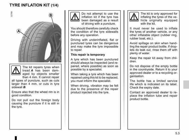
5.3
TYRE INFLATION KIT (1/4)
The kit is only approved for inflating the tyres of the ve-hicle originally equipped with the kit.
It must never be used to inflate the tyres of another vehicle, or any other inflatable object (rubber ring, rubber boat, etc.).Avoid spillage on skin when hand-ling the repair product bottle. If drop-lets do leak out, rinse them off with plenty of water.Keep the repair kit away from chil-dren.Do not dispose of the empty bottle in the countryside. Return it to your approved dealer or to a recycling or-ganisation.The bottle has a limited service life which is indicated on its label. Check the expiry date.Contact an approved dealer to re-place the inflation tube and repair product bottle.
A
B
The kit repairs tyres when tread A has been dam-aged by objects smaller than 4 mm. It cannot repair
all types of puncture, such as cuts larger than 4 mm, or cuts in tyre sidewall B.Ensure also that the wheel rim is in good condition.Do not pull out the foreign body causing the puncture if it is still in the tyre.
Do not attempt to use the inflation kit if the tyre has been damaged as a result of driving with a puncture.
You should therefore carefully check the condition of the tyre sidewalls before any operation.Driving with underinflated, flat or punctured tyres can be dangerous and may make the tyre impossible to repair.This repair is temporaryA tyre which has been punctured should always be inspected (and re-paired, where possible) as soon as possible by a specialist.When taking a tyre which has been repaired using this kit to be replaced, you must inform the specialist.When driving, vibration may be felt due to the presence of the repair product injected into the tyre.

5.4
TYRE INFLATION KIT (2/4)
In the event of a puncture, use the kit situated under the passenger footwell 1 by unscrewing the two screws 2.
With the engine running and the parking brake applied,– Connect the compressor hose 4 to
the container inlet 9;– remove the cap from the container
inflation adapter 3;– unscrew the valve cap on the rele-
vant wheel and screw on the contai-ner’s inflation adapter 3;
– disconnect any accessories pre-viously connected to the vehicle’s accessories sockets;
– the end piece 7 must be plugged in to the vehicle accessories socket;
5 63
Before using this kit, park the vehicle at a sufficient distance from traffic, switch on the hazard warning
lights, apply the handbrake, ask all passengers to leave the vehicle and keep them away from traffic.
9
If the vehicle is parked on the hard shoulder, you must warn other road users of your vehicle’s presence
with a warning triangle or with other devices as per the legislation apply-ing to the country you are in.
– press switch 5 to inflate the tyre to the recommended pressure (please refer to the information on “Tyre in-flation pressure” in Section 4);
– after a maximum of 15 minutes, stop inflating and read the pressure (on pressure gauge 6).
Note: While the container empties (approx. 30 secs), the pressure gauge 6 briefly shows pressure up to 6 bar, then the pressure drops.
– Adjust the pressure: to increase it, continue inflation with the kit; to reduce it, press button 8.
7
4
8
1
2

5.5
TYRE INFLATION KIT (3/4)
If a minimum pressure of 1.8 bar is not reached after 15 minutes, repair is not possible; do not drive the ve-hicle but contact an approved dealer.
Once the tyre is correctly inflated, remove the kit: slowly unscrew the con-tainer inflation adapter 3 to avoid any product release and store the container in plastic packaging to prevent release of the product.– Affix the driving recommendation
label (located under the container) to the dashboard where the driver can see it.
– Put the kit away.– At the end of this initial inflation op-
eration, air will still escape from the tyre. You must drive a short distance in order to seal the hole.
– Start immediately and drive at be-tween 12 and 40 mph (20 and 60 km/h) in order to distribute the product evenly in the tyre and, after driving for 2 miles (3 km), stop and check the pressure.
Nothing should be placed around the driver’s feet as such objects may slide under the pedals during
sudden braking manoeuvres and obstruct their use.
3– If the pressure is greater than 1.3 bar
but less than the recommended pressure (refer to the label affixed to the edge of the driver’s door), read-just it. Otherwise, please contact an authorised dealer: the tyre cannot be repaired.

5.6
Precautions when using the kitThe kit should not be operated for more than 15 consecutive minutes.The container must be replaced after the first use even if liquid remains inside.
TYRE INFLATION KIT (4/4)
Following repair with the kit, do not travel further than 120 miles (200 km). In addi-tion, reduce your speed and
under no circumstances exceed 48 mph (80 km/h). The sticker, which you must affix in a prominent position on the dashboard, reminds you of this.Depending on the country or local legislation, a tyre repaired with the inflation kit may need to be replaced.
Please be aware that a poorly tightened or miss-ing valve cap can make the tyres less airtight and lead
to pressure loss.Always use valve caps identical to those fitted originally and tighten them fully.

5.7
Tyre and wheel safetyThe tyres are the only contact between the vehicle and the road, so it is essen-tial to keep them in good condition. You must make sure that your tyres conform to local road traffic regulations.
When the tyre tread has been worn to the level of the warning strips, they become visible 2: it is then neces-sary to replace your tyres because the tread rubber is now only 1.6 mm deep at most, resulting in poor road hold-ing on wet roads.An overloaded vehicle, long journeys by motorway, particularly in very hot weather, or continual driving on poorly surfaced minor roads will lead to more rapid tyre wear and affect safety.
TYRES (1/3)
Incidents which occur when driving, such as striking the kerb, may damage the tyres and wheel rims, and could
also lead to misalignment of the front or rear axle geometry. In this case, have the condition of these checked by an approved dealer.
1
2
Maintaining the tyresThe tyres must be in good condition and the tread form must have sufficient depth; tyres approved by our Technical Department have wear warning strips 1 which are indicators moulded into the tread at several points.

5.8
Tyre pressuresAdhere to the tyre pressures. The tyre pressures should be checked at least once a month and additionally before any long journey (refer to the label af-fixed to the edge of the driver’s door).The pressures should be checked cold: ignore higher pressures which may be reached in hot weather or following a high speed journey.
Vehicle fitted with a tyre pressure loss warning systemIf under-inflated (puncture, low pressure
etc.), the warning light on the in-strument panel comes on. See “Tyre pressure loss warning” in Section 2.
Fitting new tyres
If the pressures cannot be checked when the tyres are cold, increase the pressures from 0.2 to 0.3 bar (or 3 PSI).Never deflate a hot tyre.
Changing wheels around
TYRES (2/3)
Please be aware that a poorly tightened or miss-ing valve cap can make the tyres less airtight and lead
to pressure loss.Always use valve caps identical to those fitted originally and tighten them fully.
Incorrect tyre pressures lead to abnormal tyre wear and unusually hot running. These are factors which
may seriously affect safety and lead to:– poor road holding,– risk of bursting or tread separa-
tion.The pressure depends on the load and the speed of use. Adjust the pressure according to the condi-tions of use (refer to the label affixed to the edge of the driver’s door). The front and rear wheels
have different dimensions. For safety reasons, it is not permitted to switch the front
wheels (tyres and/or rims) with the rear wheels.
For your safety reasons.Only tyres identical to those fitted originally or recom-mended by an approved
dealer must be used.Failure to follow these instructions could endanger your safety.This could adversely affect stabil-ity, behaviour, braking or the clear-ance between the bodywork and the tyres.Some of these effects could lead to the loss of control of the vehi-cle under certain driving condi-tions.

5.9
Snow or winter tyresIn the interests of safety (vehicle trac-tion quality), equip all four wheels of the vehicle.Warning: These tyres sometimes have a specific direction of rotation and a maximum speed index which may be lower than the maximum speed of your vehicle.Studded tyresThis type of equipment may only be used for a limited period and as laid down by local legislation. It is neces-sary to observe the speed specified by current legislation.These tyres must be fitted to all four wheels of the vehicle.
Use in winterChainsFor safety reasons, only fit chains on the rear axle.Chains must not be fitted to tyres which are larger than those originally fitted to the vehicle.
TYRES (3/3)
For your safety, please re-spect the speed limit.When they need to be re-placed, only tyres of the
same make, size, type and profile should be used on a single axle.They must have a load capacity and speed rating at least equal to those of the original tyres and correspond to the tyres recom-mended by an approved Dealer.Failure to heed these instructions could endanger your safety and affect your vehicle’s roadworthi-ness.Risk of loss of control of the ve-hicle.
16” and 17” wheels can only be fitted with chains in conjunction with spe-cific devices or equip-
ment, consult an approved Dealer.
Chains may only be fitted to tyres of the same size as those originally fitted to your vehicle.
In all cases, we would recommend that you contact an approved dealer who will be able to advise you on the choice of equipment which is most suitable for your vehicle.

5.10
For your safety, do not remove the bonnet holding straps.Risk of the bonnet falling
on the road surface.
Dipped/Main beam headlightTo change the bulb:– disconnect wiring 1;– remove cover A;– unclip the spring 3 and remove the
bulb.Bulb type: H4.It is essential to use anti-U.V. 55W bulbs so as not to damage the plastic on the headlights.Do not touch the bulb glass. Hold it by its base.When the bulb has been changed, make sure you refit the cover correctly.
FRONT HEADLIGHTS: changing bulbs (1/2)
Direction indicator lightsTurn the bulb holder 2 a quarter of a turn and take out the bulb.Bulb type: PY21W.Once the bulb has been replaced, check that it is properly secured.
A
3
2
The bulbs are under pres-sure and can break when replaced.Risk of injury.
1
Please note when work-ing close to the engine that it may be hot. The engine cooling fan may also start
at any moment. The warning light in the engine compartment re-minds you of this.Risk of injury.

5.11
Daytime running lights 4Please see an authorised dealer.
Front fog lights 5– Access the bulb holder via the un-
derneath of the vehicle;– unclip the flap;– unscrew the bulb holder.Bulb type: H16.
Any operation on (or modi-fication to) the electrical system must be performed by an approved dealer
since an incorrect connection might damage the electrical equipment (harness, components and in partic-ular the alternator). In addition, your Dealer has all the parts required for fitting these units.
FRONT HEADLIGHTS: changing bulbs (2/2)
4
5
To comply with local legislation, or as a precaution, you can obtain an emergency kit containing a set of spare bulbs and fuses from an ap-proved dealer.
Additional lightsIf you wish to fit fog lights to your ve-hicle, please see an authorised dealer.

5.12
Side lights/brake and direction indicator lights– From the boot, open the cover 1;– unscrew 2;– from outside, pull the light unit to-
wards you, pulling from the side A;
REAR AND SIDE LIGHTS: changing bulbs (1/3)
– remove the bulb holder by releasing the four clips 3;
– change the bulb;– refit the bulb holder and push the
light unit as far as it will go, until it locks into place;
– check that the light is properly locked in position;
– tighten the screw 2 and close the cover 1.
3
3
1 2
A
The bulbs are under pres-sure and can break when replaced.Risk of injury.

5.13
REAR AND SIDE LIGHTS: changing bulbs (2/3)
Number plate lights– Unclip light 9 by pressing tab 10;– remove the light cover to gain access
to the bulb.Bulb type: W5W.
10
9
High-level brake light 8Consult an approved dealer.
8
44
4 Side light and brake lightBulb type: P21/5W.
5 Direction indicator lightsBulb type: PY21W.
6 Reversing lightBulb type: P21W.
7 Fog lightBulb type: P21W.
Note: Depending on the vehicle, the re-versing and fog lights are inverted.
5 567

5.14
Side indicator lightsUnclip the indicator light 11 using a flat-blade screwdriver or similar.Turn the bulb holder a quarter of a turn and take out the bulb.Bulb type: W5W.Replace the bulb and refit the indicator light.
11
The bulbs are under pres-sure and can break when replaced.Risk of injury.
REAR AND SIDE LIGHTS: changing bulbs (3/3)

5.15
Courtesy lightUnclip the lens (using a flat-blade screwdriver or similar).Remove the bulb concerned.Bulb type 1: W5W.
INTERIOR LIGHTING: changing bulbs
The bulbs are under pres-sure and can break when replaced.Risk of injury.
Press tab 3 to release the bulb holder and access bulb 4.Bulb type: C5W festoon type bulb.
Luggage compartment lightUnclip light 2 by pressing the tabs on each side (using a flat-blade screw-driver or similar).Disconnect the light.
2
3
4
1

5.16
Radio location 1Unclip the blanking cover. The aerial, + and – supply and speaker wire connec-tions are located behind it.
Door speakers 2To install any equipment, please con-sult an authorised dealer.
FITTING A RADIO
1
2
– In all cases, it is very important to follow the manufacturer’s instruc-tions carefully.
– The specifications of the brack-ets and wires (available from our network) vary depending on the equipment level of your vehicle and the type of radio.
Consult an approved Dealer to find out the correct part number.
– No work may be carried out on the vehicle’s electrical or radio circuits, except by approved dealers: an incorrectly connected system may result in damage being caused to the electrical equipment and/or the compo-nents connected to it.

5.17
Fuses in passenger compartment AIf any electrical component does not work, check the condition of the fuses.Unclip the access flap A.
FUSES (1/3)
Fuses in engine compartment BSome functions are protected by fuses located in the engine compartment (unit B).However, because of their reduced accessibility, we advise you to have your fuses replaced by an approved Dealer.
AB
It may be necessary to use clips to remove and replace the fuses. These can be purchased at an au-thorised dealer.
Check the fuse in question and replace it, if necessary, by a fuse of the same rating.If a fuse is fitted with too high a rating, it may cause the electrical circuit to overheat (risk of fire) in the event of an item of equipment using an ex-
cessive amount of current.
To comply with current legislation, or as a precaution, you can obtain an emergency kit from your approved dealer containing a set of spare bulbs and fuses.
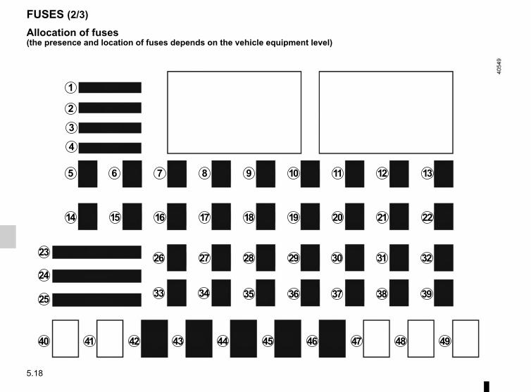
5.18
FUSES (2/3)
Allocation of fuses(the presence and location of fuses depends on the vehicle equipment level)
1
2
3
4
5 6 7 8 9 10 11 12 13
14 15 16 17 18 19 2220 21
23
25
2426 27 28 29 30 31 32
33 34 35 36 37 38 39
40 41 42 43 44 45 46 47 48 49

5.19
Number Allocation
1 “Starting” position on the ignition-starter switch
2 Power-assisted steering3 Lighting4 Airbags5 Lighting6 Instrument panel7 Alarm8 UCE energy management9 UCE energy management
10 Passenger compartment ECU
11 Direction indicator lights
12 Passenger compartment ECU
13 Passenger compartment ECU
14 Electric windows
15 ESC/steering wheel angle sensor/automatic gearbox
16 Courtesy lights/air conditioning
17 Locking/unlocking the doors/ESC
18 Rear-view mirrors
19 Brake lights
FUSES (3/3)
Number Allocation
20Headlight beam height/rear parking distance control/front camera adjustment
21 Injection
22 Reversing light/rear windscreen wiper
23 “Starting” position on the ignition-starter switch
24 «Accessory» position on the ignition switch/service relay
25 Front windscreen wiper
26 Radio/energy management
27 Daytime running lights28 Accessories socket
29 UCE energy management
30 Horn
31 Rear fog light
32 “Accessory” position on the ignition-starter switch
33 Exterior lights/Rear side lights
Number Allocation
34energy management ECU/passenger compartment ECU/headlights/daytime running lights
35 Right headlight/energy management ECU
36 Left headlight/passenger compartment ECU
37 Right-hand main beam headlight
38 Left headlight/passenger compartment ECU
39 Bicycle carrier40 Not used41 Not used42 Fog lights43 Radio amplifier
44 Automatic gearbox
45 Electric windows/one-touch windows
46 Electric door mirrors
47 Not used
48 Not used49 Not used

5.20
Replacing the batteryOpen the case at slot 1 using a flat-blade screwdriver or similar, and re-place the battery 2, observing the type and polarity shown on the back of the cover.
Note: It is not advisable to touch the electronic circuit in the key cover when replacing the battery.
RADIO FREQUENCY REMOTE CONTROL: batteries (1/2)
2
When refitting, ensure that the cover is correctly clipped on and the screw tightened.
The batteries are available from ap-proved Dealers, and their service life approximately two years.Check that there is no dye on the battery: risk of an incorrect electri-cal contact.
1
A
A B
B
1
2

5.21
Operating faultsIf the battery is too weak to ensure cor-rect operation, you can still start and lock/unlock the vehicle (please refer to the information on “Locking/unlocking the opening elements” in Section 1).
Do not throw away your used batteries; give them to an organisation responsible for collecting and recycling
batteries.
RADIO FREQUENCY REMOTE CONTROL: batteries (2/2)

5.22
BATTERY: troubleshooting (1/3)
To avoid all risk of sparks:– Ensure that any electrical consumers
(courtesy lights, etc.) are switched off before disconnecting or recon-necting the battery.
– When charging, stop the charger before connecting or disconnecting the battery.
– Do not place metal objects on the battery to avoid creating a short cir-cuit between the terminals.
– Always wait at least one minute after the engine has been switched off before disconnecting a battery.
– Make sure that you reconnect the battery terminals after refitting.
Connecting a battery chargerThe battery charger must be com-patible with a battery with nominal voltage of 12 volts.Do not disconnect the battery while the engine is running. Follow the instruc-tions given by the manufacturer of the battery charger you are using.
Special procedures may be required to charge some batteries. Contact your ap-proved dealer.
Avoid all risk of sparks which may cause an immediate explosion, and charge the battery in a well venti-lated area. Risk of serious injury.
Handle the battery with care as it contains sulphuric acid, which must not come into contact with eyes or skin. If
it does, wash the affected area with plenty of cold water.Ensure that naked flames, red hot objects and sparks do not come into contact with the battery as there is a risk of explosion.The engine may be hot when car-rying out operations in close prox-imity. In addition, the engine cooling fan can come on at any moment.Risk of injury.

5.23
34
BATTERY: troubleshooting (2/3)
Depending on the vehicle, unclip the red protective cover to access termi-nal 2 (+).Connect the positive cable B to the ter-minal 2 (+) then to the terminal 3 (+) of the battery supplying the current.Connect the negative cable A to the terminal 4 (–) of the battery supplying the current, then to the terminal 1 (–) of the discharged battery.
Starting the vehicle using the battery from another vehicleIf you have to use the battery from an-other vehicle to start, obtain suitable jump leads (with a large cross section) from an approved dealer or, if you al-ready have jump leads, ensure that they are in perfect condition.The two batteries must have an iden-tical nominal voltage of 12 volts. The battery supplying the current should have a capacity (amp-hours, Ah) which is at least the same as that of the dis-charged battery.Ensure that there is no risk of contact between the two vehicles (risk of short circuiting when the positive terminals are connected) and that the discharged battery is properly connected. Switch off your vehicle ignition.Start the engine of the vehicle supply-ing the current and run it at an interme-diate engine speed. Check that there is no con-
tact between cables A and B, and that the positive cable B is not touching any
metal parts of the vehicle supplying the current.Risk of injury and/or damage to the vehicle.
1
2
21
BA
For your safety, do not remove the bonnet holding straps. Risk of the bonnet falling on the road surface.

5.24
Start the engine. As soon as it is run-ning, disconnect the cables A and B in reverse order ( 1 - 4 - 3 - 2 ) and posi-tion the red protective cover by press-ing it down.
BATTERY: troubleshooting (3/3)
34
21
BA
Follow the instructions on the label C.
C

5.25
ACCESSORIES
Electrical and electronic accessoriesBefore installing this type of accessory (particularly for transmitters/receivers: frequency bandwidth, power level, po-sition of the aerial, etc.), make sure it is compatible with your vehicle. You can get advice from an authorised dealer.Connect accessories with a maximum power of 120 Watts only. Fire hazard. When several accessory sockets are
used at the same time, the total power of the connected accessories must not exceed 180 watts.No work may be carried out on the vehicle’s electrical or radio circuits, except by authorised dealers: an incorrectly connected system may result in damage being caused to the electrical equipment and/or the components connected to it.If the vehicle is fitted with any aftermarket electrical equipment, make sure that the installation is correctly protected by a fuse. Establish the rating and position of this fuse.
Using the diagnostic socketThe use of electronic accessories on the diagnostic socket may cause serious disturbance to the vehicle’s electronic systems. For your safety we recommend that you use only electronic accessories approved by the manufacturer, consult an Approved Dealer. Serious accident risk.
Use of transmitting/receiving devices (telephones, CB equipment etc.).Telephones and CB equipment with integrated aerials may cause interference to the electronic systems originally fitted to the vehicle: it is advisable only to use equipment with an external aerial. Furthermore, we remind you of the need to conform to the legislation in force concerning the use of such equipment.
Fitting aftermarket accessoriesIf you wish to install accessories on the vehicle: please contact an authorised dealer. Also, to ensure the correct operation of your vehicle, and to avoid any risk to your safety, we recommend that you use only accessories specifically designed for your vehicle, which are the only accessories for which the manufacturer will provide a warranty.If you are using an anti-theft device, only attach it to the brake pedal.Obstructions to the driverOn the driver’s side, only use mats suitable for the vehicle, attached with the pre-fitted components, and check the fitting regu-larly. Do not lay one mat on top of another. There is a risk of wedging the pedals.

5.26
WINDSCREEN WIPER BLADES (1/2)
2
1
3
4
Replacing windscreen wiper blades 1Ignition switched off,– Lift the wiper arm 2;– turn blade 1.– lower the tab 3 by pressing on each
side A.– push the blade forwards B to release
the hook 4.
To refitProceed in reverse order. Make sure that the blade is correctly locked in po-sition.
A
AB
– In frosty weather, make sure that the wiper blades are not stuck by ice (to avoid the risk of the motor
overheating).– Check the condition of the wiper
blades.They should be replaced as soon as they become less efficient: ap-proximately once a year.
When changing the blade, when it has been removed, do not let the wiper arm fall against the window: risk of breaking the window.
Check the condition of the wiper blades. You are responsible for their service life:– clean the blades, windscreen and
rear screen regularly with soapy water;
– do not use them when the wind-screen or rear screen are dry;
– free them from the windscreen or rear screen when they have not been used for a long time.

5.27
5
6
Rear screen wiper blade 5Ignition switched off,– Lift the wiper arm 5;– release the blade 6 by pulling it.
To refitProceed in reverse order. Make sure that the blade is correctly locked in po-sition.
WINDSCREEN WIPER BLADES (2/2)

5.28
TOWING: breakdown recovery (1/2)
Towing a vehicle with an automatic gearboxWith the engine switched off, the trans-mission is no longer lubricated. It is preferable to tow this type of vehicle on a trailer or tow it with the rear wheels off the ground.In exceptional circumstances, you may tow it with all four wheels on the ground, only in a forward gear, with the gear in neutral position N, over a maxi-mum distance of 31 miles (50 km) and not exceeding a speed of 15.5 mph (25 km/h).If the gear lever cannot be put into the N position, please consult an autho-rised dealer.
1
2
Before any towing, put the gears into neutral (neutral position for vehicles equipped with a manual gearbox or N position for vehicles equipped with an automatic gearbox).Unlock the steering column; the igni-tion key must be in “M” position (ig-nition) to enable signalling (“Stop” lights, hazard warning lights, etc.). Always switch on the lights when driving at night.Release the parking brake.It is also essential to observe the towing regulations imposed by current legisla-tion in your country. Please contact an authorised dealer.
When the engine is stopped, steering and brak-ing assistance are not op-erational.
Do not remove the key from the ignition when the vehi-cle is being towed.
3
If the lever is locked in position P, even though you are depressing the brake pedal and pressing the unlock-ing button 1, the lever can still be re-leased manually. To do this, unclip the base of the gear lever 2 starting on the side below the air conditioning controls. Then raise the button 3 and simulta-neously press the unlock button 1 on the lever.Contact an authorised dealer as soon as possible.

5.29
TOWING: breakdown recovery (2/2)
Only use the front and rear towing points 4.(never use the drive shafts or any other part of the vehicle)This towing point may only be used for towing: never use it for lifting the vehi-cle directly or indirectly.
Access to towing pointsUnclip the cover 6 by inserting a flat-blade screwdriver or similar under the cover. Screw in the tow eye 5 by hand as far as possible.Only use the tow eye 5 located under the passenger footwell alongside the inflation kit; unscrew the two screws 8.
6
5
4
Never leave tools unse-cured in the vehicle: there is a risk that they may be thrown about during brak-
ing. After use, check that the tow eye is properly stored away in its housing: there is a risk of injury.
5
8
– Use a rigid towing bar. If a rope or cable is used (where the law allows this), the vehicle being towed
must be able to brake.– A vehicle must not be towed if it is
not fit to be driven.– Avoid accelerating or braking
suddenly when towing, as this may result in damage being caused to the vehicle.
– In all cases, it is advisable not to exceed 15.5 mph (25 km/h).
– Do not push the vehicle if the steering column is locked.

5.30
OPERATING FAULTS (1/6)
Using the remote control POSSIBLE CAUSES ACTION REQUIRED
The remote control does not lock or unlock the doors.
The remote control battery is flat. Use the emergency key.
Use of appliances operating on the same frequency as the remote control (mobile phone, etc.).
Stop using the devices or use the key.
Vehicle located in a high electromagnetic radiation zone.Discharged battery.
Replace the battery or have it replaced. You can still lock/unlock and start your vehicle (refer to the information on “Locking/unlocking the doors” in Section 1 and “Starting/Stopping the engine” in Section 2).
The vehicle is started. With the engine running, the key’s locking/unlocking device is blocked. Turn off the ignition.

5.31
The starter is activated POSSIBLE CAUSES WHAT TO DO
The instrument panel indicator lights are weak or fail to light up and the starter does not turn.
Battery terminals disconnected, oxidised or incorrectly secured.
Retighten, reconnect or clean them if they are oxidised.
Battery discharged or worn. Connect another battery to the faulty bat-tery. Refer to the paragraph “Battery: trou-bleshooting” in Section 5 or replace the bat-tery if necessary.Do not push the vehicle if the steering column is locked.
The engine will not start. Starting conditions are not fulfilled. Refer to the information on “Starting/stop-ping the engine” in Section 2.
The steering column remains locked. Steering wheel locked. To unlock, move the key and steering wheel (see “Starting, stopping the engine” in Section 2).
OPERATING FAULTS (2/6)The following advice will enable you to carry out quick, temporary repairs. For safety reasons, you should always contact an approved Dealer as soon as possible.

5.32
On the road POSSIBLE CAUSES WHAT TO DO
Vibrations. Tyres not inflated to the correct pres-sure, incorrectly balanced or dam-aged.
Check the tyre pressures: if this is not the problem, have them checked by an ap-proved Dealer.
Coolant boiling in the coolant reservoir. Mechanical fault: damaged cylinder head gasket.
Stop the engine.Contact an approved Dealer.
Smoke under the bonnet. Short circuit or cooling system leak. Stop, switch off the ignition, stand away from the vehicle and contact an approved dealer.
The oil pressure warning light comes on:
while cornering or braking The level is too low. Top up the engine oil level (refer to the in-formation on “Engine oil level: topping up/filling” in Section 4).
is slow to go out or remains lit under acceleration
Loss of oil pressure. Stop the vehicle and contact an approved Dealer.
OPERATING FAULTS (3/6)

5.33
On the road POSSIBLE CAUSES WHAT TO DO
Steering becomes heavy. Assistance overheating.Fault with the electric assistance motor.Fault in the assistance system.
Drive carefully at reduced speed, be aware of the level of force in the steering wheel needed to turn the wheels. Consult an ap-proved dealer
The engine overheats. The coolant temperature indicator and the warn-ing light ® come on.
Engine cooling fan not working. Stop the vehicle, switch off the engine and contact an approved Dealer.
Coolant leaks. Check the coolant reservoir: it should con-tain fluid. If there is no coolant, consult an approved Dealer as soon as possible.
OPERATING FAULTS (4/6)
Radiator: If there is a lack of coolant, remember that it must never be topped up using cold coolant while the engine is very warm. After any procedure on the vehicle which has involved even partial draining of the cooling system, it must be refilled with a new mixture prepared in the correct proportions. Reminder: only products approved by our Technical Department may be used for this purpose.

5.34
OPERATING FAULTS (5/6)
Electrical equipment POSSIBLE CAUSES WHAT TO DOThe wipers do not work. Wiper blades stuck. Free the blades before using the wipers.
Faulty electrical circuit. Consult an approved dealer.
Fuse damaged. Replace the fuse or have it replaced; refer to the information in the “Fuses” section.
The wiper does not stop. Faulty electrical controls. Consult an approved dealer.
Direction indicators flashing more quickly.
Blown bulb. See information on “Headlights: changing bulbs” or “Rear and side lights: changing bulbs”.
The direction indicators do not work. Faulty electrical circuit or control. Consult an approved dealer.
Fuse damaged. Replace the fuse or have it replaced; refer to the information in the “Fuses” section.
The lights do not come on or go off. Faulty electrical circuit or control. Consult an approved dealer.
Fuse damaged. Replace the fuse or have it replaced; refer to the information in the “Fuses” section.

5.35
Electrical equipment POSSIBLE CAUSES WHAT TO DOTraces of condensation in the lights and headlights.
Traces of condensation may be a nat-ural phenomenon caused by varia-tions in temperature and humidity.In this case, the traces will disappear slowly once the lights are switched on.
The front seat belt reminder light comes on when the seat belts are fastened.
An object is stuck between the floor and the seat and is disrupting the op-eration of the sensor.
Remove all objects from underneath the front seats.
OPERATING FAULTS (6/6)

5.36

6.1
Section 6: Technical specifications
Vehicle identification plates . . . . . . . . . . . . . . . . . . . . . . . . . . . . . . . . . . . . . . . . . . . . . . . . . . . . . . . . 6.2Engine identification plate . . . . . . . . . . . . . . . . . . . . . . . . . . . . . . . . . . . . . . . . . . . . . . . . . . . . . . . . . 6.3Dimensions . . . . . . . . . . . . . . . . . . . . . . . . . . . . . . . . . . . . . . . . . . . . . . . . . . . . . . . . . . . . . . . . . . . . 6.4Engine specifications . . . . . . . . . . . . . . . . . . . . . . . . . . . . . . . . . . . . . . . . . . . . . . . . . . . . . . . . . . . . . 6.5Towing weights . . . . . . . . . . . . . . . . . . . . . . . . . . . . . . . . . . . . . . . . . . . . . . . . . . . . . . . . . . . . . . . . . 6.6Weights . . . . . . . . . . . . . . . . . . . . . . . . . . . . . . . . . . . . . . . . . . . . . . . . . . . . . . . . . . . . . . . . . . . . . . . 6.6Replacement parts and repairs . . . . . . . . . . . . . . . . . . . . . . . . . . . . . . . . . . . . . . . . . . . . . . . . . . . . . 6.7Service sheets . . . . . . . . . . . . . . . . . . . . . . . . . . . . . . . . . . . . . . . . . . . . . . . . . . . . . . . . . . . . . . . . . . 6.8Anticorrosion check . . . . . . . . . . . . . . . . . . . . . . . . . . . . . . . . . . . . . . . . . . . . . . . . . . . . . . . . . . . . . . 6.14

6.2
VEHICLE IDENTIFICATION PLATES
A
B
The information shown on the ve-hicle identification plate should be quoted on all correspondence or orders.The presence and location of the in-formation depends on the vehicle.
Vehicle identification plate A 1 Manufacturer name. 2 EC design number or approval
number. 3 Identification number.
Depending on the vehicle, this information is also given on marking B.
4 MMAC (Maximum permissible all-up weight).
5 MTR (Gross Train Weight) 6 MMTA (Maximum Permissible
Weight) front axle. 7 MMTA rear axle. 8 Reserved for related or additional
entries. 9 Paint reference (colour code).
A
78
9 6
432
1
5

6.3
Please quote the information on the engine plate or label A in all corre-spondence or orders.(Location varies depending on engine)
1 Engine type.
2 Engine suffix.
3 Engine number.
ENGINE IDENTIFICATION PLATES
A
A
21
3

6.4
1,875
1,544* to 1,554*
DIMENSIONS (in metres)
1,434 to 1,444 (1)1,434 to 1,442 (2)
(1) Vehicle with 15” wheels(2) Vehicle with 16” wheels* unladen
1,454 (1) to 1,4590,630 à 0,638 2,492 to 2,495 0,473 à 0,490 1,430 (2) to 1,459
3,595 to 3,623
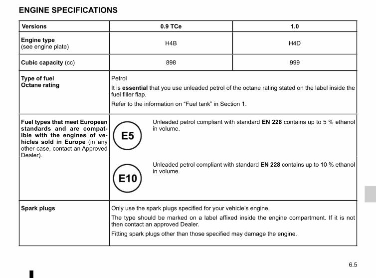
6.5
ENGINE SPECIFICATIONS
Versions 0.9 TCe 1.0
Engine type(see engine plate) H4B H4D
Cubic capacity (cc) 898 999
Type of fuelOctane rating
PetrolIt is essential that you use unleaded petrol of the octane rating stated on the label inside the fuel filler flap.Refer to the information on “Fuel tank” in Section 1.
Fuel types that meet European standards and are compat-ible with the engines of ve-hicles sold in Europe (in any other case, contact an Approved Dealer).
Unleaded petrol compliant with standard EN 228 contains up to 5 % ethanol in volume.
Unleaded petrol compliant with standard EN 228 contains up to 10 % ethanol in volume.
Spark plugs Only use the spark plugs specified for your vehicle’s engine.The type should be marked on a label affixed inside the engine compartment. If it is not then contact an approved Dealer.Fitting spark plugs other than those specified may damage the engine.

6.6
WEIGHTS (in kg)
The weights indicated for a basic vehicle without options: they vary depending on the your vehicle’s equipment. Consult your approved Dealer.
Maximum permissible all-up weight (MMAC)Maximum permissible all-up weight (MMTA)Gross Train Weight (MTR)
Weights are indicated on the vehicle identification plate (refer to the information on “Vehicle identification plates” in Section 6)
Braked Trailer Weight* Prohibited
Unbraked Trailer Weight* Prohibited
Permissible nose weight* Prohibited
Maximum permissible load on roof 60 kg (including the carrying device)

6.7
Original parts are based on strict specifications and are subject to highly-specialised tests. Therefore, they are of at least the same level of quality as the parts fitted originally.If you always fit genuine replacement parts to your vehicle, you will ensure that it performs well. Furthermore, repairs carried out within the manufacturer’s Network using original parts are guaranteed according to the conditions set out on the reverse of the repair order.
REPLACEMENT PARTS AND REPAIRS

6.8
Date: Miles (Km): Invoice number: Comments/miscellaneousType of operation: StampService □....................................... □Anti-corrosion check:OK □ Not OK* □*See specific page
Date: Miles (Km): Invoice number: Comments/miscellaneousType of operation: StampService □....................................... □Anti-corrosion check:OK □ Not OK* □*See specific page
Date: Miles (Km): Invoice number: Comments/miscellaneousType of operation: StampService □....................................... □Anti-corrosion check:OK □ Not OK* □
*See specific page
VIN: ..................................................................................
SERVICE SHEETS (1/6)

6.9
SERVICE SHEETS (2/6)
VIN: ..................................................................................
Date: Miles (Km): Invoice number: Comments/miscellaneousType of operation: StampService □....................................... □Anti-corrosion check:OK □ Not OK* □*See specific page
Date: Miles (Km): Invoice number: Comments/miscellaneousType of operation: StampService □....................................... □Anti-corrosion check:OK □ Not OK* □*See specific page
Date: Miles (Km): Invoice number: Comments/miscellaneousType of operation: StampService □....................................... □Anti-corrosion check:OK □ Not OK* □
*See specific page

6.10
SERVICE SHEETS (3/6)
VIN: ..................................................................................
Date: Miles (Km): Invoice number: Comments/miscellaneousType of operation: StampService □....................................... □Anti-corrosion check:OK □ Not OK* □*See specific page
Date: Miles (Km): Invoice number: Comments/miscellaneousType of operation: StampService □....................................... □Anti-corrosion check:OK □ Not OK* □*See specific page
Date: Miles (Km): Invoice number: Comments/miscellaneousType of operation: StampService □....................................... □Anti-corrosion check:OK □ Not OK* □
*See specific page

6.11
SERVICE SHEETS (4/6)
VIN: ..................................................................................
Date: Miles (Km): Invoice number: Comments/miscellaneousType of operation: StampService □....................................... □Anti-corrosion check:OK □ Not OK* □*See specific page
Date: Miles (Km): Invoice number: Comments/miscellaneousType of operation: StampService □....................................... □Anti-corrosion check:OK □ Not OK* □*See specific page
Date: Miles (Km): Invoice number: Comments/miscellaneousType of operation: StampService □....................................... □Anti-corrosion check:OK □ Not OK* □
*See specific page

6.12
SERVICE SHEETS (5/6)
VIN: ..................................................................................
Date: Miles (Km): Invoice number: Comments/miscellaneousType of operation: StampService □....................................... □Anti-corrosion check:OK □ Not OK* □*See specific page
Date: Miles (Km): Invoice number: Comments/miscellaneousType of operation: StampService □....................................... □Anti-corrosion check:OK □ Not OK* □*See specific page
Date: Miles (Km): Invoice number: Comments/miscellaneousType of operation: StampService □....................................... □Anti-corrosion check:OK □ Not OK* □
*See specific page

6.13
VIN: ..................................................................................
Date: Miles (Km): Invoice number: Comments/miscellaneousType of operation: StampService □....................................... □Anti-corrosion check:OK □ Not OK* □*See specific page
Date: Miles (Km): Invoice number: Comments/miscellaneousType of operation: StampService □....................................... □Anti-corrosion check:OK □ Not OK* □*See specific page
Date: Miles (Km): Invoice number: Comments/miscellaneousType of operation: StampService □....................................... □Anti-corrosion check:OK □ Not OK* □
*See specific page
SERVICE SHEETS (6/6)

6.14
ANTICORROSION CHECK (1/5)
If the continuation of the warranty is subject to repair, it is indicated below.
VIN: ..........................................................
Corrosion repair operation to be carried out:
Stamp
Date of repair:
Repair to be carried out: Stamp
Date of repair:
Repair to be carried out: Stamp
Date of repair:

6.15
ANTICORROSION CHECK (2/5)
If the continuation of the warranty is subject to repair, it is indicated below.
VIN: ..........................................................
Corrosion repair operation to be carried out:
Stamp
Date of repair:
Repair to be carried out: Stamp
Date of repair:
Repair to be carried out: Stamp
Date of repair:

6.16
ANTICORROSION CHECK (3/5)
If the continuation of the warranty is subject to repair, it is indicated below.
VIN: ..........................................................
Corrosion repair operation to be carried out:
Stamp
Date of repair:
Repair to be carried out: Stamp
Date of repair:
Repair to be carried out: Stamp
Date of repair:

6.17
ANTICORROSION CHECK (4/5)
If the continuation of the warranty is subject to repair, it is indicated below.
VIN: ..........................................................
Corrosion repair operation to be carried out:
Stamp
Date of repair:
Repair to be carried out: Stamp
Date of repair:
Repair to be carried out: Stamp
Date of repair:

6.18
ANTICORROSION CHECK (5/5)
If the continuation of the warranty is subject to repair, it is indicated below.
VIN: ..........................................................
Corrosion repair operation to be carried out:
Stamp
Date of repair:
Repair to be carried out: Stamp
Date of repair:
Repair to be carried out: Stamp
Date of repair:

7.1
ALPHABETICAL INDEX (1/5)AABS ..............................................................1.46, 2.26 → 2.29accessories........................................................................ 5.25accessories socket ............................................................ 3.22additional methods of restraint .......................................... 1.21
side protection ............................................................. 1.20to the front seat belts .......................................1.15 → 1.18to the rear seat belts .................................................... 1.19
adjusting your driving position ......................1.11 → 1.14, 3.23advice on antipollution ....................................................... 2.15air bag...........................................................1.15 → 1.21, 1.44
activating the front passenger air bags ........................ 1.38deactivating the front passenger air bags .................... 1.36
air conditioning ........................................................3.4 → 3.12air vents ...................................................................... 3.2 – 3.3anti-corrosion check ..............................................6.14 → 6.18anti-corrosion protection .................................................... 4.14anti-lock braking system: ABS ...............................2.26 → 2.29antipollution
advice .......................................................................... 2.15ashtray ............................................................................... 3.22audible and visual signals.................................................. 1.61automatic gearbox (use) ........................................2.43 → 2.46automatic gearbox selector lever...........................2.43 → 2.46
Bbattery...........................................................4.11, 5.22 → 5.24
troubleshooting ................................................5.22 → 5.24battery (remote control) .......................................... 5.20 – 5.21brake fluid ............................................................................ 4.9bulbs
changing ..........................................................5.10 → 5.15
Ccatalytic converter................................................................ 2.9central door locking .................................1.2 – 1.3, 1.8 → 1.10
changing a bulb .....................................................5.10 → 5.15changing gear ...............................................2.10, 2.43 → 2.46child restraint/seat .............................1.23 – 1.24, 1.26 → 1.36child safety.........................1.7, 1.18, 1.23 – 1.24, 1.26 → 1.36child seats..........................................1.23 – 1.24, 1.26 → 1.35children .......................................................... 1.23 – 1.24, 1.24children (safety) ................................................................... 1.7cigar lighter ........................................................................ 3.22cleaning:
inside the vehicle .............................................. 4.17 – 4.18clock ....................................................................... 1.56 – 1.57closing the doors .....................................................1.6 → 1.10control instruments ............................1.44 → 1.51, 1.56 – 1.57controls ..................................................................1.40 → 1.43courtesy light ............................................................ 3.16, 5.15cruise control ................................................1.47, 2.35 → 2.38crosswind assist ................................................................ 2.27cruise control-speed limiter....................................2.32 → 2.38crosswind assist function ................................................... 2.27
Ddashboard..............................................................1.40 → 1.43demisting
rear screen ..................................................3.4, 3.7 → 3.10windscreen ..................................................3.5, 3.7 → 3.10
dimensions .......................................................................... 6.4dipstick................................................................................. 4.3display ...................................................................1.44 → 1.49doors/tailgate ....................................................1.4, 1.6 → 1.10driver assistance....................................................2.26 → 2.42driver’s position .....................................................1.40 → 1.48driving ..........2.3, 2.9, 2.11 → 2.14, 2.26 → 2.29, 2.32 → 2.40, 2.43 → 2.46driving aids ............................................................2.26 → 2.42driving position
settings ............................................................1.12 → 1.14

7.2
ALPHABETICAL INDEX (2/5)driving recommendations ......................................2.11 → 2.14
EECO driving ...........................................................2.11 → 2.14ECO mode ......................................................................... 2.12electric beam height adjustment ............................. 1.62 – 1.63electric windows ..................................................... 3.13 – 3.14electronic stability control: ESC .............................2.26 → 2.29emergency brake assist.........................................2.26 → 2.29emergency braking ................................................2.26 → 2.29engine
access ............................................................................ 4.2technical specifications .................................................. 6.5
engine access flap ............................................................... 4.2engine coolant ..................................................................... 4.8engine oil ...................................................................4.3 → 4.5engine oil capacity ...................................................... 4.4 – 4.5engine oil level ...........................................................4.3 → 4.5engine specifications .................................................... 6.3, 6.5engine standby ..........................................................2.5 → 2.8environment ....................................................................... 2.16ESC: electronic stability control ....................1.46, 2.26 → 2.29external temperature ......................................................... 1.57
Ffaults
operating faults ................................................5.30 → 5.35filter
air filter ......................................................................... 4.10oil filter .................................................................. 4.4 – 4.5passenger compartment filter ...................................... 4.10
fitting a radio ...................................................................... 5.16fittings ....................................................................3.17 → 3.21front engine cover ....................................................... 4.6 – 4.7front passenger air bag deactivation ................................. 1.36front seat adjustment ......................................................... 1.11
front seatsadjustment ........................................................ 1.11 – 1.12
fueladvice on fuel economy ...................................2.11 → 2.14consumption ................................1.52 – 1.53, 2.11 → 2.14filling ......................................................... 1.44, 1.68 – 1.69grade ................................................................. 1.68 – 1.69
fuel consumption ...................... 1.52 – 1.53, 2.11 → 2.14, 3.11fuel economy .........................................................2.11 → 2.14fuel filler cap ........................................................... 1.68 – 1.69fuel level ................................................................... 1.44, 1.49fuel tank
capacity ........................................................................ 1.68fuel tank capacity .................................................... 1.68 – 1.69fuses ......................................................................5.17 → 5.19
Ggear lever........................................................................... 2.10glove box ........................................................................... 3.17grab handle........................................................................ 3.21
Hhandbrake.......................................................................... 2.10hands-free telephone integrated control ............................ 3.30hazard warning lights signal .............................................. 1.61headlight beam adjustment .................................... 1.62 – 1.63headrest............................................................................. 3.23heated seats ...................................................................... 1.11heated windscreen ..................................................3.7 → 3.10heating and air conditioning system ........................3.4 → 3.11heating system ........................................................3.4 → 3.12Hill Start Assist.......................................................2.26 → 2.29horn ................................................................................... 1.61horn:
flash ............................................................................. 1.61

7.3
ALPHABETICAL INDEX (3/5)Iignition switch ............................................................. 2.2 – 2.3indicators ......................................................1.61, 5.10 → 5.14indicators:
direction indicators ....................................................... 1.61instrument panel ..............................................1.49 → 1.55
instrument panel ....................................................1.44 → 1.55interior trim
maintenance ..................................................... 4.17 – 4.18Isofix ......................................................................1.26 → 1.28
Kkeys ...........................................................................1.2 → 1.4
Llane departure warning ........................................... 2.30 – 2.31levels .......................................................................4.8 → 4.10levels:
brake fluid ...................................................................... 4.9coolant ........................................................................... 4.8windscreen washer reservoir ....................................... 4.10
lighting:exterior .............................................................1.58 → 1.63instrument panel .......................................................... 1.58interior ................................................................. 3.16, 5.15
lightsadjustment ........................................................ 1.62 – 1.63changing bulbs .................................................. 5.10 – 5.11front ................................................................... 5.10 – 5.11
lights:adjusting ........................................................... 1.62 – 1.63brake lights .................................................................. 5.13dipped beam headlights ......... 1.44, 1.58, 5.10 – 5.11, 5.13direction indicators .......................... 1.44, 1.61, 5.10 – 5.11fog lights .................................................... 1.44, 1.60, 5.13hazard warning ............................................................ 1.61
main beam headlights ................................ 1.44, 1.58, 5.10reversing lights ............................................................. 5.13side lights ........................................ 1.58, 5.10 – 5.11, 5.13
load permitted on the roof.................................................... 6.6locking the doors ..............................................1.4, 1.6 → 1.10luggage compartment cover .............................................. 3.26
Mmaintenance ...................................................................... 2.15maintenance:
bodywork .........................................................4.14 → 4.16interior trim ........................................................ 4.17 – 4.18mechanical .........................................4.3, 4.11, 6.8 → 6.13
map reading lights ............................................................. 3.16methods of restraint in addition to the seat belts ...1.15 → 1.21multimedia equipment .............................................. 3.30, 5.16
Nnavigation system .............................................................. 3.30
Ooil change ................................................................... 4.4 – 4.5opening the doors ......................................................1.6 → 1.9operating faults ................................1.44 → 1.48, 5.30 → 5.35
Ppaintwork
maintenance ....................................................4.14 → 4.16parking distance control.......................................... 2.39 – 2.40power-assisted steering..................................................... 1.22pretensioners .........................................................1.15 → 1.18puncture.....................................................................5.2 → 5.6
Rradio................................................................................... 3.30

7.4
ALPHABETICAL INDEX (4/5)radio frequency remote control/key
use .......................................................................1.2 → 1.4rear bench seat.................................................................. 3.24rear lights
number plate lights ...................................................... 5.13rear seats........................................................................... 1.14
functions ...................................................................... 3.24rear view camera .................................................... 2.41 – 2.42rear view mirrors ................................................................ 1.39remote control door locking
batteries ............................................................ 5.20 – 5.21remote control door locking unit ................................1.2 → 1.4RENAULT ANTI-INTRUDER DEVICE (RAID) ................... 1.10replacement parts ................................................................ 6.7reverse gear
selecting ..................................................2.10, 2.43 → 2.46reversing sensor ..................................................... 2.39 – 2.40roof bars ............................................................................ 3.29roof rack
roof bars ....................................................................... 3.29running in ............................................................................. 2.2
Sseat belt pretensioners
front seat belt ...................................................1.15 → 1.18seat belts .............................................1.12 → 1.18, 1.21, 1.48service sheets..........................................................6.8 → 6.13side indicator lights
changing bulbs ............................................................. 5.14side protection devices ...................................................... 1.20signals and lights ...................................................1.58 → 1.63speakers
location ........................................................................ 5.16special features of petrol vehicles ....................................... 2.9speed limiter .................................................1.47, 2.32 → 2.34starting the engine .....................................2.2 – 2.3, 2.5 → 2.8
steering wheeladjustment ................................................................... 1.22
Stop & Start ......................................................1.47, 2.5 → 2.8Stop & Start function..................................................2.5 → 2.8stopping the engine ............................................................. 2.3storage compartment.............................................3.17 → 3.21storage compartments ...........................................3.17 → 3.21sun visor ............................................................................ 3.20sunroof............................................................................... 3.15switching on the vehicle ignition ................................. 2.2 – 2.3
Ttailgate ........................................................... 3.25, 3.27 – 3.28tanks and reservoirs
brake fluid ...................................................................... 4.9coolant ........................................................................... 4.8
tanks and reservoirs:windscreen washer ...................................................... 4.10
technical specifications ..............................................6.4 → 6.7telephone ........................................................................... 3.30temperature regulation ............................................3.7 → 3.12towing
breakdown ........................................................ 5.28 – 5.29towing a caravan ................................................................. 6.6towing hitch........................................................................ 5.29towing rings ....................................................................... 3.28towing weights ..................................................................... 6.6transporting children ..........................1.23 – 1.24, 1.26 → 1.36transporting objects
in the luggage compartment ........................................ 3.28on the roof ...................................................................... 6.6
trip computer and warning system...1.44 → 1.48, 1.50 → 1.55tyre inflation kit...........................................................5.3 → 5.6tyre pressure...............................2.17 → 2.25, 4.12 – 4.13, 5.8tyre pressure loss warning.....................................2.17 → 2.25tyre pressures .................................................. 4.12 – 4.13, 5.8

7.5
ALPHABETICAL INDEX (5/5)tyres ........................2.14, 2.17 → 2.25, 4.12 – 4.13, 5.7 → 5.9
Uunlocking the doors .................................................... 1.8 – 1.9
Vvariable power-assisted steering ....................................... 1.22vehicle identification plates .................................................. 6.3ventilation ................................................................3.2 → 3.12
Wwarning lights.........................................................1.44 → 1.55washing .................................................................4.14 → 4.16weights ................................................................................ 6.6wheels (safety) ..........................................................5.7 → 5.9windscreen de-icing/demisting ................................3.7 → 3.10windscreen washer ................................................1.64 → 1.67wiper blades ........................................................... 5.26 – 5.27wipers ....................................................................1.64 → 1.67
blades ............................................................... 5.26 – 5.27

7.6

A passion for performance
ELF, partner of
RENAULT recommends ELFPartners in cutting-edge automotive technology, Elf and Renault combine their expertise on both the racetrack and the city streets. This enduring partnership gives drivers a range of lubricants perfectly suited to Renault cars. Lasting protection and optimum performance for your engine – guaranteed. Whether changing the oil or simply topping up, to find the approved ELF lubricant best suited to your vehicle, ask your Renault dealer for a recommendation or consult your vehi-cle maintenance handbook.
www.lubricants.elf.com
A brand from
2016-Elf-ENG.indd 1 18/05/2016 14:20

RENAULT S.A.S. SOCIÉTÉ PAR ACTIONS SIMPLIFIÉE AU CAPITAL DE 533 941 113 € / 13-15, QUAI LE GALLO 92100 BOULOGNE-BILLANCOURT R.C.S. NANTERRE 780 129 987 — SIRET 780 129 987 03591 / TÉL. : 0810 40 50 60
NU 1035-10 – 99 91 044 60S – 04/2018 – Edition anglaise
à999104460Sñêòä FN