remote i/o systems – product overview i...connection to centum vp more than 1,500 lb/fb remote i/o...
TRANSCRIPT

1
PROCESS AUTOMATIONPROCESS AUTOMATION
COMBINE TRADITION AND FUTURECOMBINE TRADITION AND FUTUREREMOTE I/O SYSTEMS PRODUCT OVERVIEW
PROCESS AUTOMATION

PEPPERl+FUChS PROCESS AUTOMATION
BUSINESS OVERVIEW
Pepperl+Fuchs offers proven industry expertise through market-driven, customer-focused products that provide answers to the toughest application problems. We service the chemical, pharmaceutical, oil & gas, petrochemical, and other areas including waste water treatment, and power technology.
In all industrial areas, Pepperl+Fuchs is both a supplier and partner for end users, control systems manufacturers, system integrators and engineering contractors.
From our expert application analysis and global key account management, to our on-site engineering of new systems and technical support after the sale, we stand solidly behind every product we build.
ThE EXPERTS IN PROCESS AUTOMATION
Remote I/O Introduction
Remote I/O System Integration
Remote I/O System Architecture
lB Remote I/O for Safe Area,Zone 2, Div. 2, or Zone 22
FB Remote I/O for hazardous AreasZone 1, or Zone 21
Customized Solutions
Foundation Fieldbus Modular I/O
Ethernet Remote I/O
Zone 1 Accessories –Multi Function Terminal
Zone 1 Accessories –Fiber Optic PROFIBUS Repeater
P. 03
P. 04
P. 08
P. 10
P. 12
P. 14
P. 15
P. 16
P. 18
P. 19
TABlE OF CONTENT
2

3
Remote I/O is a signal conditioning system that offers significant savings in many areas compared with other methods of instrumentation. This is particularly true when upgrading existing installations and when building new systems that will continue using traditional signals for digital and analog inputs and outputs.
PEPPERl+FUChS COVERS VARIOUS STANDARDS
PROFIBUS Modbus RTU FOUNDATION fieldbus Ethernet, e. g., with Modbus TCP
A wide spectrum of single and multi channel I/O devices offer intrinsi cally safe and increased safety field connections for sensors and actuators. This ensures that engineering becomes easy and adaptable to the needs of any plant concept.
DECIDING ON REMOTE I/O
REMOTE I/O INTRODUCTION
YOUR BENEFITS OF REMOTE I/O
INTERNATIONAl SAFETY STANDARDS
Safety Integrity Level SIL2 is available for select digital and analog output modules using a bus independent hardware shut down.
Proven in use redundancy for all major DCS systems Single channel high integrity and multi channel compact I/O More channels per slave for maximum packing density and
the minimum number of cabinets The same engineering in all hazardous areas IS I/O can be mounted adjacent to non IS I/O Ethernet or RS485 bus options

4
REMOTE I/O SYSTEM INTEGRATION
System integration for Remote I/O has now become a reliable and manageable part of process automation, as is demonstrated by the installation of hundreds of thousands of modules in conjunction with control systems from all renowned DCS vendors.
FDT/DTM AND EDDlREMOTE I/O FOR All APPlICATIONS
The FDT/DTM concept is even more user-friendly than the GSD-basedPROFIBUS configuration and has been supported by Pepperl+Fuchs from the outset.
YOUR BENEFITS OF FDT/DTM AND EDDl
Complete integration in the process control system’s environment
DTM certification by an independent laboratory
Interoperability for all vendors during the product life cycle
As an alternative, DTMs and EDDL can be operated from an independent workstation to separate them from the process control system
Separate workstations ensure that there is no interaction with the control system
Software can be updated on separate workstations without affecting the main system functionality
Updates in the system environment are tested in our laboratories
EDDL meets the same criteria but, unlike DTM, does not representa piece of software but rather a text file describing the devices.
DTM and EDDL technologies can be used for all major busses.
Pepperl+Fuchs has a worldwide presence, employing approximately5,000 people. Well-trained service technicians and consultants are available in all markets.
Local service, worldwide Commissioning assistance Fast remote service using PC anywhere Telephone assistance Personal customer service at the local level Training courses tailored to your needs
INTERNATIONAl SERVICE
LB Remote I/O for Zone 2 or Class 1, Div. 2 and the safe area as well as FB Remote I/O for installation in Zone 1 are integrated into all major process control systems and PLCs.
ThE FUNCTIONAlITY IS VERIFIED IN A NUMBER OF WAYS Agreements with system vendors to ensure support during the
life cycle of the plant
Close cooperation with engineering companies
Pepperl+Fuchs supplies certified configuration software as DTM or EDD
Close cooperation with recognized, independent test laboratories e. g. BIS Prozesstechnik GmbH or Dietz Automation GmbH and IFAK System GmbH
Well-known control systems are available in our laboratories for continuous integration tests
We use tried-and-tested methods to connect to high-level process control systems and PLCs.
Standard busses like PROFIBUS or Modbus run under all regular operating systems, irrespective of changes in the Windows®* world and are unaffected by changes in system releases
Operation, monitoring, configuration, parameterization and diagnosis can be managed from the process control system’s own user interface
Complies with NE105, ensuring secure system integration, even for updates - Integration tests control updates and version changes - Remote I/Os are compatible when updating on the system side - Modern Remote I/Os tolerate system updates
External tools can be used but are not necessary
* Windows is a registered trademark of the Microsoft Corporation.
SIMPlE, SECURE SYSTEM INTEGRATION
SYSTEM PARTNERShIPS

5
PRODUCT lIFE CYClE MANAGEMENT
Pepperl+Fuchs Remote I/O systems have been in use worldwide for more than 10 years and are under continuous development. The chemical, petrochemical and pharmaceutical industries, as well as the oil and gas sector expect a plant to run reliably for at least 10 to 15 years after commissioning.
Pepperl+Fuchs, therefore, provides compatible products suitable for the life cycle of any plant
Life cycle agreements with system vendors such as ABB and others
Life cycle service agreements in projects
User support from consulting and engineering to commissioning and service
Contracts and agreements with system vendors to ensure interoperability
Continuous development of compatible units, so that products meet the latest standards and regulations
Pepperl+Fuchs is an active member of international bodies such as PNO, the FDT Group, the Fieldbus Foundation, and the HART Communication Foundation. We are also represented on the executive board of the PACTware consortium.
Remote I/O offers extensive possibilities for the remote control of connected field devices employing HART communications.
hART® COMMUNICATION
Configuring and parameterizing field devices via the bus Stretching service intervals through regular monitoring of
the relevant field device parameters Use HART secondary variables to save on measuring points Some systems offer HART communication directly from their
engineering consoles Separate, system-independent control terminal available HART communication possible without a service bus Standard configuration software can be used with EDDL or
FDT/DTM technology
YOUR BENEFITS OF hART COMMUNICATION
HART is regarded as a proven in use technology in new plants. When it comes to modernizing existing systems, installed HART®*field devices can be given an added dimension without any extra efforts.
*HART is a registered trademark of the HART® Communication Foundation

REMOTE I/O SYSTEM INTEGRATION
SYSTEM VENDOR
hONEYWEllSYSTEM VENDOR
ABB
location
Germany – chemical plant
Redundant PROFIBUS in operation since 1999
System description
12,000 measuring points connected to ABB Symphony. Now extended to over 18,000 I/O points.
Other Remote I/O systems on the site are connected to ABB Symphony and ABB Freelance AC800F.
Successful migration for ABB Contronic P installations at other locations equipped with Remote I/O.
Advantages
Complete integration employing the FDT/DTM concept
Reliable and interference-free operation
Life cycle service agreement
location
Ireland – pharmaceutical industry
PROFIBUS in operation since 2002
System description
GAMP (good automation manufacturing practice)
Frequent plant extensions using Remote I/O for Emerson DeltaV.
Other major projects in Portugal use a redundant PROFIBUS.
Advantages
Complete integration thanks to GSE and FHX files
Simple handling in the system environment
AMS integrated
HART via class 2 master
location
Germany – chemical plant
Redundant PROFIBUS in operation since 2005
System description
Honeywell has developed Remote I/O drivers to connect to Experion.
Drivers offer improved handling ability
The interpretation of the Remote I/O signals at the control level is made particularly easy.
Advantages
Integration by means of GSE files and software drivers
Simple engineering
Many more system integrations via PROFIBUS and Modbus from ABB, Allen Bradley, Bernecker+Rainer, HIMA, Hitachi, Mitsubishi,Matsushita and Schneider Electric are in use world wide.
6
SYSTEM VENDOR
EMERSON

7
SYSTEM VENDOR
YOKOGAWASYSTEM VENDOR
SIEMENSSYSTEM VENDOR
INVENSYS
location
Worldwide
RS485 standard-compliant HDLC bus available
System description
Complete integration through shared development of FBM functionality for the LB/FB Remote I/O modules
Auto-configuration of the Remote I/O
Configuration, parameterization, diagnosis and HART communication from the operator level of the process control system
Advantages
Identical behaviour for both Invensys and Pepperl+Fuchs I/O devices
Best possible use of system interfaces
More compact than comparable solutions
location
Germany – agricultural crop protection
Redundant PROFIBUS in operation since 2000
System description
Siemens S7-417H with redundant PROFIBUS DPV1.
Originally approx. 4,000 I/O channels, now expanded to over 8,000 channels with LB Remote I/O
Single-channel modules are important here in order to guarantee plant availability
Use of SIL2 shutdowns and watchdog circuits for additional bus monitoring
Advantages
Software drivers offer very convenient handling ability in the system environment by interpreting the Remote I/O signals at the control level.
Siemens PDM Asset Management Tool is approved for LB/FB Remote I/O
location
Italy, Poland
Redundant PROFIBUS in operation since 2007
System description
Connection to Centum VP
More than 1,500 LB/FB Remote I/O channels
First extensions have already been completed
HART communication can also be used with a class 2 master via the PROFIBUS or service bus
Advantages
Integration by means of a GSD file
Simple handling in the system environment
HART via class 2 master
7
Complete project list on request
haza
rdou
s Ar
ea Z
one
2/Cl
ass
I, Di
v. 2
haza
rdou
s Ar
ea, Z
one
1
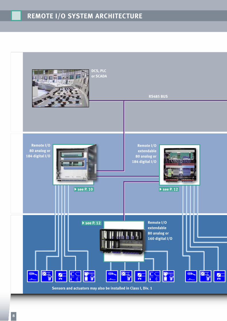
DCS, PlCor SCADA
RS485 BUS
Remote I/O 80 analog or
184 digital I/O
Remote I/Oextendable
80 analog or184 digital I/O
Cont
rol R
oom
Remote I/Oextendable80 analog or160 digital I/O
Sensors and actuators may also be installed in Class I, Div. 1
REMOTE I/O SYSTEM ARChITECTURE
see P. 10
see P. 12
see P. 12
8

Remote I/O are often installed in the safe area control room nextto the DCS or PLC. This leads to a very flexible, easily extendable interface solution.
Sensors and actuators to measure and control process values can be located in Zone 1 or even in Zone 0 or Class I, Div. 1.
CONTROl ROOM INSTAllATION
In Zone 2 or Class I, Div. 2 area explosion hazards are rare and are only present for a short period of time.
Remote I/O are often installed in Zone 2 close to the plant level. The documentation supplied offers guidance regarding permitted application and installation. This is based on the required temperature class, the expected ambient temperature and also normal operating conditions.
Sensors and actuators to measure and control process values can be located in Zone 1 or even in Zone 0 or Class I, Div. 1.
Make sure to use Zone 2, or Zone 22 or Div. 2 approved housings depending on the application.
ZONE 2 OR ClASS I, DIV. 2 INSTAllATION
In Zone 1 explosion hazards may exist occasionally.
More and more Remote I/O are installed in Zone 1 on the plant level. The documentation supplied offers guidance regardingthe permitted extensions. This is based on the required temperature class, the expected ambient temperature and also possible fault conditions.
Sensors and actuators to measure and control process values are also located in Zone 1 or even in Zone 0 or Class I, Div. 1.
Make sure to use Zone 1, or Zone 21 approved housings depending on the application.
ZONE 1 INSTAllATION
Remote I/O4 slaves per cabinet
80 analog or 184 digital I/O each
9

LB Remote I/O is mounted on a backplane that snaps onto a standard DIN rail. The backplane supplies power to the modules andprovides the internal wiring between the bus communi cation interface (ComUnits or gateways) and the I/O devices.
Two gateways can be fitted to achieve redundancy. In this caseboth connections have to be made to the fieldbus and the re dundant fieldbus connectors. The type of fieldbus used determines the model number of the gateway.
An extension cable allows the gateway to be used for a maximumof 80 analog or 184 digital input or output channels. Other backplane sizes are available.
lB REMOTE I/O
NAMUR sensors, mechanical and electronic switches
Analog output e.g., for proportional valves and solenoids
Temperature signals from 2-, 3- and 4-wire RTD
Thermocouple inputs
Analog inputs for 2- and 4-wire transmitters
Current sources
I/P converters
APPlICATIONS
User friendly plug-in modules with removable terminals
Hot swap maintenance without hot work permit
I/O-modules for NON Ex or Ex-i (IS) and Ex-e field connections
I/O modules can be mounted on the backplane in any order
Single channel modules for high integrity can be combined with multi channel I/O for maximum packing density
Decentralized installation saves wiring
SAFE AREA OR ZONE 2, DIV. 2 MEChANICS
Fiber Optic link Zone 2Long distances between the control room and Zone 2 Remote I/O can be bridged using a PROFIBUS Fiber Optic Link.
ACCESSORIES
Com Unit for:Modbus,
PROFIBUS,Ethernet
Redundant Com Unit
Extension todouble the I/O count
Fieldbus
Redundantfieldbus
Service bus option
Single- and multi-channel modules can be combined
lB REMOTE I/O FOR SAFE AREA, ZONE 2, DIV. 2, OR ZONE 22
10

11
Inputs and outputs rated for Zone 1, Zone 0 and Div. 1
INPUT/OUTPUT SIGNAlS
May be plugged in or removed from a live circuit in Zone 2 / Div. 2
Tag labels
Tagging strip
Hot swappable modules
Powersupplies
Redundantpowersupply
IS and NON IS modulescan be mounted side byside. Only requiresconnector hood to achieve50 mm spacing
Plug-inscrew and spring cage connectors.
11

ACCESSORIES
Cable to extension unitto double the I/O count
Increased safetyredundant fieldbus
Redundant power
Redundant bus coupler PROFIBUS Modbus Ethernet
Service bus
FB Remote I/O is mounted on a backplane that fits glass fiberreinforced polyester (GRP) or stainless steel enclosures. The backplane supplies power to the modules and provides the internal wiring between the bus communication interface (ComUnits or gateways) and the I/O devices.
Two gateways can be fitted to achieve redundancy. In this case both connections have to be made to the fieldbus and the redundant fieldbus terminals. The type of fieldbus used de ter mines the model number of the gateway.
An extension cable allows the gateway to be used for a maximum of 80 analog or 196 digital input or output channels. As the modules contain the same electronics as those for Zone 2 engineering is the same for all areas. Other enclosure sizes are available.
FB REMOTE I/O
NAMUR sensors, mechanical and electronic switches
Analog output e.g., for proportional valves and solenoids
Temperature signals from 2-, 3- and 4-wire RTD
Thermocouple inputs
Analog inputs for 2- and 4-wire transmitters
Current sources
I/P converters
APPlICATIONS
User friendly plug-in modules with removable terminals
Hot swap maintenance without hot work permit
I/O-modules for NON Ex or Ex-i (IS) and Ex-e field connections
I/O modules can be mounted on the backplane in any order
Single channel modules for high integrity can be combined with multi channel I/O for maximum packing density
Decentralized installation saves wiring
ZONE 1 MEChANICS
24 V DC115 V AC230 V AC
Power SupplyBus
Termination
Fiber Optic link Zone 1Long distances between the control room and Zone 1 Remote I/O can be bridged using a PROFIBUS Fiber Optic Link
FB REMOTE I/O FOR hAZARDOUS AREAS ZONE 1, OR ZONE 21
12

13
Tag labels per module
Primary bus couplerPROFIBUS Modbus Ethernet
BusTermination
Hot swappable I/O modules
Inputs and outputs rated for Zone 1 and Zone 0
INPUT/OUTPUT SIGNAlS
Single and multichannelEx-i and Ex-e modulescan be combined on the same backplane
Flanged box for easy cable entry and screens
Plug-inscrew and spring cage connectors.
FB REMOTE I/O FOR hAZARDOUS AREAS ZONE 1, OR ZONE 21
13
Increasedsafety optionsupon enquiry.

14
VisuNet Remote monitors and Panel PCs transfer data via Ethernet and does not require proprietary structures so changes of the topology of a plant can be made quickly and easily. VisuNet is approved for zones 1+21 (ATEX and IECEx) and compatible with all established PC-based distributed control systems (DCS). It can be used to control plant operations via Remote I/O. VisuNet meets even the toughest requirements on robustness, safety and functionality.
CUSTOMIZED SOlUTIONS
COMPlETE SOlUTIONS – FAST INSTAllATION TO SUIT INDIVIDUAl NEEDS
Pepperl+Fuchs products are used thoughout the world involving industrial, hazardous, and corrosive environments. Close cooperation with our customers allows our project engineers to
provide complete solutions in a variety of panels and enclosures. Customized and standard solutions are equally competetively priced and ensure the fastest possible installation on site.
CONTROl ROOM INSTAllATIONControl cabinet with process control system and space for three remote I/O sta tions with 3 x 46 slots for 240 analog signals or a combination of these. Dimensions: 800 x 2000 x 400 mm
ZONE 1/ZONE 21Customized FB Remote I/O with added valve banks, marshalling terminals and replaceable power fuses 80 analog I/O or 196 digital I/O or a combination of analogs and digitals.Dimensions: 800 x 1000 x 300 mm.
ZONE 2 / DIV. 2
Standard stainless steel housing with LB Remote I/O for 80 analog or 184 digital I/Os or a combination.Dimensions: 800 x 800 x 300 mm
ZONE 1/ZONE 22
Customized GRP FB Remote I/Owith increased safety wiring to replaceable fuses. Flanged enclosures made up of standard 544 x 272 x 212 mm boxes.
NETWORK BASED PROCESS VISUAlIZATION CERTIFICATES
Pepperl+Fuchs equipment is supplied with a wide range of certificates from ATEX to IECEx to UL and many others for gas hazardous areas Zone 0, Zone 1, Zone 2, and Div. 1, Div. 2 or dust hazards in Zone 21, Zone 22, and Class III. In addition we offer FAT (factory acceptance tests) and GAMP procedures.
Marine certificates are also available for offshore or other marine applications.
Many output modules are available with a hard wired bus independent shut-down input. This allows outputs to be disabled at the push ofa button or under the control of a safety system without having to wait for bus response times.
SIl2 FUNCTIONAl SAFETY

FOUNDATION FIElDBUS MODUlAR I/O
FOUNDATION FIElDBUS SOlUTION
CUSTOMIZED SOlUTIONS
Remote I/O are increasingly used for plant retrofits in brown field applications but also for new installations in green field plants. They even appear in conjunction with Foundation fieldbus systems to support all non Foundation fieldbus signals.
The modular I/O stations take up one just one address on the Foun dation fieldbus for up to 40 digital signals or 20 analog I/O.
The I/O boxes only load the bus with the minimum 10 – 12 mA required by the standard. The power supply taps into the standard 24 V DC available around the plant in Class I, Div 2. There is also a 230 V or 115 V bulk power supply available when required.
hART service bus
Fieldbus
hOSTWORKSTATION
FF Modular I/Oin Zone 2, Div. 2
FF Modular I/Oin Zone 1
USB/RS485
15

EThERNET REMOTE I/O
Zone 1Zone 2, Div. 2
WORK STATION
FACTORY lEVElBus cycle time< 1000 ms
Bus cycle time< 10 ms
FIElD-lEVEl
CEll-lEVElBus cycle time< 100 ms
INTERNET/INTRANETEThERNET/TCP/IP
MANAGEMENT PC/VME
EThERNET/TCP/IP
DCS/PlCModbus TCP master
PROCESS CONTROl SYSTEM MAINTENANCE
EThERNET Modbus TCP
Zone 0, Div.1
Industrial Ethernet is already widely used in the industry and is now finding its way into process instrumentation. Together with Remote I/O it can now be used on green field sites and even more so on legacy plants. In the past the communication path was based on
the field-proven RS485 hardware using PROFIBUS or Modbus protocols. Now industrial ETHERNET is moving forward. All major DCS vendors offer industrial Ethernet links with the Modbus TCP protocol.
INDUSTRIAl EThERNET REAChES ZONE 2/DIV. 2, AND ZONE 1
SYSTEM ARChITECTURE
16

MODBUS TCP ZONE 2/DIV. 2 REMOTE I/O
The system architecture shows how industrial ETHERNET stretches from the control room to the field. Remote I/O is used to adapt all kinds of traditional digital and analog signals from NAMUR and
temperature sensors, contacts, and frequency signals to solenoid or proportional valves, and positioners.
Industrial Ethernet even reaches Zone 1 hazardous areas employing increased safety cables. These make additional intrinsically safe
converters superfluous cutting costs, simplifying the installation, and even ensuring higher availability.
MODBUS TCP ZONE 1 REMOTE I/O
YOUR BENEFITS
ETHERNET Remote I/O is easily integrated into the DCS environment using the long-established Modbus TCP standard
Practically everyone is familiar with Modbus. No extensive training required to learn about how to configure the Remote I/O
Ethernet switches are directly linked to Remote I/O in hazardous areas using enhanced safety Ex-e technology rather than employing additional isolators
80 analog, 184 digital channels per slave allow a very high packing density
Mounted in Zone 2 or Div. 2 hazardous areas. Separate Zone 1 version.
Optional power, bus, and gateway redundancy
YOUR BENEFITS
Ethernet is available from all major DCS vendors
Ethernet makes use of existing network topologies. It is, therefore, often not necessary to lay new bus cables
The Ethernet backbone of DCS and PLC architectures ensures that customers are familiar with Ethernet technology
Network administrators can employ standard fault finding procedures
No new hardware training required for service engineers
RJ45Detail ofredundantEthernetconnection
17

ZONE 1 ACCESSORIES – MUlTI FUNCTION TERMINAl
APPlICATIONS
Fusing Ex-d solenoids, alarm indicators, sounders and diode decoupling of power supplies
Simple OR-Gate for Zone 1 mounting, visible separation for field devices, relay switches, and power circuits
Bus termination
Current limiter
Isolating relay
DO
DO
Example: solenoid driver loop Example: redundant power supply
Resistor module Dual diode module
Multi function terminal with plug-in base
The multi function terminal for hazardous areas offers more energy than intrinsically safe circuits. This leads to the following advantages:
Can be fitted with various type of modules including diodes, relays and other simple circuits
Hot-swap in Zone 1
ADVANTAGESPOWER hOT SWAP IN ZONE 1
Wires can be disconnected during operation once the module has been removed Maintenance
without hotwork permit
Saves timeduringservicing
Multi function terminal after having been removed from the base
Energy loops become interruptible as if theywere intrinsically safe
Simplifies engineering
Bus termination module Diode module
Fuse module Relay module
18
hOUSING TYPES
DIN-rail module GRP polyester housing Stainless steel housing
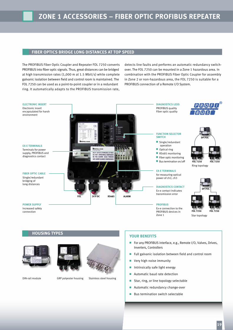
ZONE 1 ACCESSORIES – FIBER OPTIC PROFIBUS REPEATER
FOl 24 V DC RS485 AlARM
ElECTRONIC INSERT
POWER SUPPlY PROFIBUS
DIAGNOSTICS CONTACT
EX-E TERMINAlS
DIAGNOSTICS lEDS
FUNCTION SElECTOR SWITCh
For any PROFIBUS interface, e.g., Remote I/O, Valves, Drives, Inverters, Controllers
Full galvanic isolation between field and control room
Very high noise immunity
Intrinsically safe light energy
Automatic baud rate detection
Star, ring, or line topology selectable
Automatic redundancy change-over
Bus termination switch selectable
The PROFIBUS Fiber Optic Coupler and Repeater FOL 7250 converts PROFIBUS into fiber optic signals. Thus, great distances can be bridged at high transmission rates (1,000 m at 1.5 Mbit/s) while complete galvanic isolation between field and control room is maintained. The FOL 7250 can be used as a point-to-point coupler or in a redundant ring. It automatically adapts to the PROFIBUS transmission rate,
detects line faults and performs an automatic redundancy switch-over. The FOL 7250 can be mounted in a Zone 1 hazardous area. In combination with the PROFIBUS Fiber Optic Coupler for assembly in Zone 2 or non-hazardous area, the FOL 7250 is suitable for a PROFIBUS connection of a Remote I/O System.
Electronic insert encapsulated for harsh environment
Increased safetyconnection
Ex-e connection to the PROFIBUS devices in Zone 1
Ex-e contact indicatestransmission error
for measuring opticalpower of ch2, ch3
PROFIBUS qualityFiber optic quality
Single/redundant operation
Optical ring RS485 monitoring Fiber optic monitoring Bus termination on/off
EX-E TERMINAlS
FIBER OPTIC CABlE
Terminals for powersupply, PROFIBUS anddiagnostics contact
Single/redundantbridging of long distances
FIBER OPTICS BRIDGE lONG DISTANCES AT TOP SPEED
YOUR BENEFITS
Ring topologyFOl 7250 FOl 7250
DP/FOl
Star topologyFOl 7250 FOl 7250
DP/FOl
19

5 1
8
4
2
6
7
3
PROTECTING YOUR PROCESS
Subject to modifications • Copyright Pepperl+Fuchs • Printed in Germany • Part No. 197500 06/11 05
For over a half century, Pepperl+Fuchs has been continually providing new concepts for the world of process automation. Our company sets standards in quality and innovative technology. We develop, produce and distribute electronic interface modules, Human-Machine Interfaces and hazardous location protection equipment on a global scale, meeting the most deman-ding needs of industry. Resulting from our world-wide presence and our high flexibility in production and customer service, we are able to individually offer complete solutions – wherever and whenever you need us. We are the recognized experts in our technologies – Pepperl+Fuchs has earned a strong reputation by supplying the world’s largest process industry companies with the broadest line of proven components for a diverse range of applications.
www.pepperl-fuchs.com
PROCESS AUTOMATION – PROTECTING YOUR PROCESS
Southern/Eastern Europe headquartersPepperl+Fuchs s.r.l. Sulbiate (MB) · ItalyTel. +39 039 62921E-Mail: [email protected]
Northern Europe headquartersPepperl+Fuchs GB Ltd. Oldham · EnglandTel. +44 161 6336431E-Mail: [email protected]
Southern America headquartersPepperl+Fuchs Ltda.São Bernardo do Campo · SP · Brazil Tel. +55 11 4007 1448 E-Mail: [email protected]
Worldwide/German headquarters Pepperl+Fuchs GmbH Mannheim · GermanyTel. +49 621 776 2222E-Mail: [email protected]
North/Central America headquarters Pepperl+Fuchs Inc. Twinsburg · Ohio · USATel. +1 330 486 0002E-Mail: [email protected]
Western Europe & Africa headquartersPepperl+Fuchs N.V. Schoten/Antwerp · BelgiumTel. +32 3 6442500E-Mail: [email protected]
Asia Pacific headquartersPepperl+Fuchs PTE Ltd. SingaporeCompany Registration No. 199003130ETel. +65 6779 9091E-Mail: [email protected]
Middle East/India headquartersPepperl+Fuchs M.E (FZE)Dubai · UAETel. +971 4 883 8378E-mail: [email protected]
1
2
3
4
5
6
7
8