remote control system having symmetrical tone, send/receive
TRANSCRIPT
United States Patent [191 Dolikian et al.
[54] REMOTE CONTROL SYSTEM HAVING SYMMETRICAL TONE, SEND/RECEIVE SIGNALING CIRCUITS FOR RADIO
[75]
[73] [21] [22] [51] [52]
[53]
[561'
COMMUNICATIONS
Inventors: Armin V. Dolikian, Palatine; Michael D. Kotzin, Buffalo Grove; Brian J. Budnik, Schaumburg, all of Ill.
Assignee: Motorola, Inc., Schaumburg, Ill.
Appl. No.: 568,170 Filed: Jan. 4, 1984
Int. Cl.4 . ........... .. H04B 1/00; H04B 7/00
U.S. Cl. ...................................... .. 455/70; 455/36; 340/825.48; 340/825.76; 379/102
Field of Search ................... .. 455/4, 5, l4, 15, 35, 455/36, 54, 56, 58, 68, 70; 179/2 A, 2 AM, 2 DP, 2.51, 37, 84 VF, 170.4; 340/825.48, 825.73,
825.76; 370/76, 110.1, 124
References Cited
U.S. PATENT DOCUMENTS
2,401,024 5/ 1946 Sateren ............................. .. 179/2 A 3,288,932 l1/l966 Cleary et a1. 179/2 DP 3,335,227 8/ 1967 Jackel . . . . . . . . . . . . .. 179/2 A
3,383,467 5/1968 New et al. ..... .. 179/2 A 3,405,234 10/1968 West . . . . . . . . . . . . . .. 179/2 A
3,436,487 4/1969 Blane .............................. .. 179/2 DP
3,577,080 5/1971 Cannalte . 3,614,326 10/1971 Cameron . 3,647,971 3/1972 Cushman et a1. ................. .. 179/2 A 3,651,407 3/1972 Sarallo et al. . . . . . . . . . . . . .. 455/36
3,655,915 4/1972 Liberman et a1. .. 179/2 DP 3,675,513 7/1972 Flanagan et a1. .............. .. 179/2 DP 3,725,589 4/ 1973 Golden . 3,746,793 7/ 1973 Sachs et a1. .................... .. 179/2 DP 3,927,265 12/1975 Roedel et a1. 179/2 DP 3,955,051 S/ 1976 Bitzer et a1. 179/2 DP 4,122,305 10/1978 Fish et a1. ...... .. .. 179/2 A
4,122,307 lO/ 1978 Suehiro .............. .. 179/2 A 4,131,849 12/1978 Freeburg et al. . . . . . . . .. 455/58
4,184,118 1/1980 Cannalte et al. . 455/68 4,208,631 6/ 1980 Beseke et al. 455/92 4,209,131 6/ 1980 Barash et a1. . . . . . . . . .. 239/68
4,268,721 5/1981 Nielson et a1. . 179/2 DP 4,302,629 1l/ 1981 Foulkes et al. ................ .. 179/2 DP
[11] Patent Number: 4,654,881 [45] Date of Patent: Mar. 31, 1987
4,377,726 3/1983 Schiffbauer etal 4,393,277 7/1983 Besen etal 4,430,755 2/1984 Nadir etal 4,578,537 3/1986 Faggin etal. .................. .. 179/2 DP
OTHER PUBLICATIONS
“Coding Scheme Sends Data by Tone Signals”—K. Smith, Electronics, vol. 52, No. 8, pp. 68-70, Apr. 12, 1979.
Primary Examiner-Jin F. Ng Attorney, Agent, or Firm-Raymond A. Jenski; Donald B. Southard
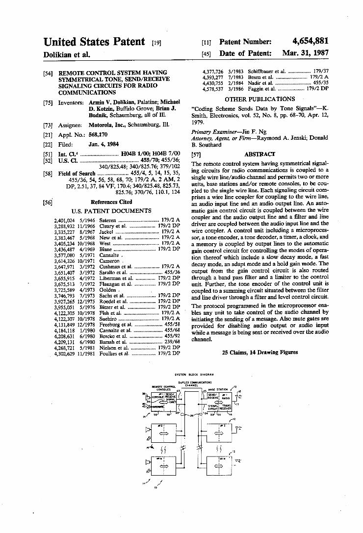
[57] ABSTRACI‘ The remote control system having symmetrical signal ing circuits for radio communications is coupled to a single wire line/audio channel and permits two or more units, base stations and/or remote consoles, to be cou pled to the single wire line. Each signaling circuit com prises a wire line coupler for coupling to the wire line, an audio input line and an audio output line. An auto matic gain control circuit is coupled between the wire coupler and the audio output line and a ?lter and line driver are coupled between the audio input line and the wire coupler. A control unit including a microproces sor, a tone encoder, a tone decoder, a timer, a clock, and a memory is coupled by output lines to the automatic gain control circuit for controlling the modes of opera tion thereof which include a’slow decay mode, a fast decay mode, an adapt mode and a hold gain mode. The output from the gain control circuit is also routed through a band pass ?lter and a limiter to the control unit. Further, the tone encoder of the control unit is coupled to a summing circuit situated between the ?lter and line driver through a ?lter and level control circuit.
The protocol programmed in the microprocessor ena bles any unit to take control of the audio channel by initiating the sending of a message. Also mute gates are provided for disabling audio output or audio input while a message is being sent or received over the audio channel.
25 Claims, 14 Drawing Figures
SYSTEM BLOCK DIAGRAM
REMOTE CONTROL CON SOLES
IIIS D EN / CONSOLEI IECKNE
| SIGNAL
DUPLEX COHMWIUTIONS CNANNEL
27
5.
'2 23 us: snnon / la
SEun/ : an RECENEI “mo

U. S. Patent Mar. 31', 1987
FIG. I
Sheet 1 of 11
‘ SYSTEM BLOCK DIAGRAM
REMOTE CONTROL CON SOLES
CHANNEL
2| SIGNAL CIRC'T
#I | SEND/ CONSOLEI RECEIVE
DUPLEX COMMUNICATIONS
4,654,881
I2 BASE STATION l8
SEND/ : # | RECEIVE | RADIO
SIGNA : TRANS. CIRCUIT IRECEIVER
\
>
U. S. Patent Mar. 31, 1987 Sheet 2 of 1 l 4,654,881
FIG‘. 2 MAJOR ELEMENTS OF SIGNALLING CIRCUIT
BASE STATION
49 WIRE LINE {56 {58 44 23 QJUPLER 55 I57 / 60
S ToJ-O- 52 GATED NoTcI-I AUDIO TO "\_/’ AGC/ T R
WIRE a AMPLIF‘ER 88 F'L E RF TRANSIs EINE - I
24 / Q54 17? FSI P75 93 5o \ T ADAPT HOLD I4” ACTIVITY 99 MUTE!
) _
“8 '°°\-- LEVEL é LOW-PASSIf97 CONTROL FILTER -
III A GAIN I GAIN 2
N OTCH J RCV A'UDIO / FILTER FROM
22 , RECEIVER l6 — )
L '04 62 MUTEZ f
672 72 64 73 \ 6 Z RE I > suARoToNE
g LIMITER BAND PASS STATION 68 FILTER FUNCTIONS
_ —<->
GT/FT <— SELECT ‘—
__ N “w
z 3 c’ 20 STATION
6 3 G1}__ 86 98 KEY ' mp; OLD SLOW/ ACTI- J3m
IO8IO9TONE 8| 92 7a 90 14 TONES 95 94 DECODE - ENCODE 69 9e
CONTROL UNIT 70
U. S. Patent Mar. 31, 1987
FIG. 3
Sheet 3 of 11
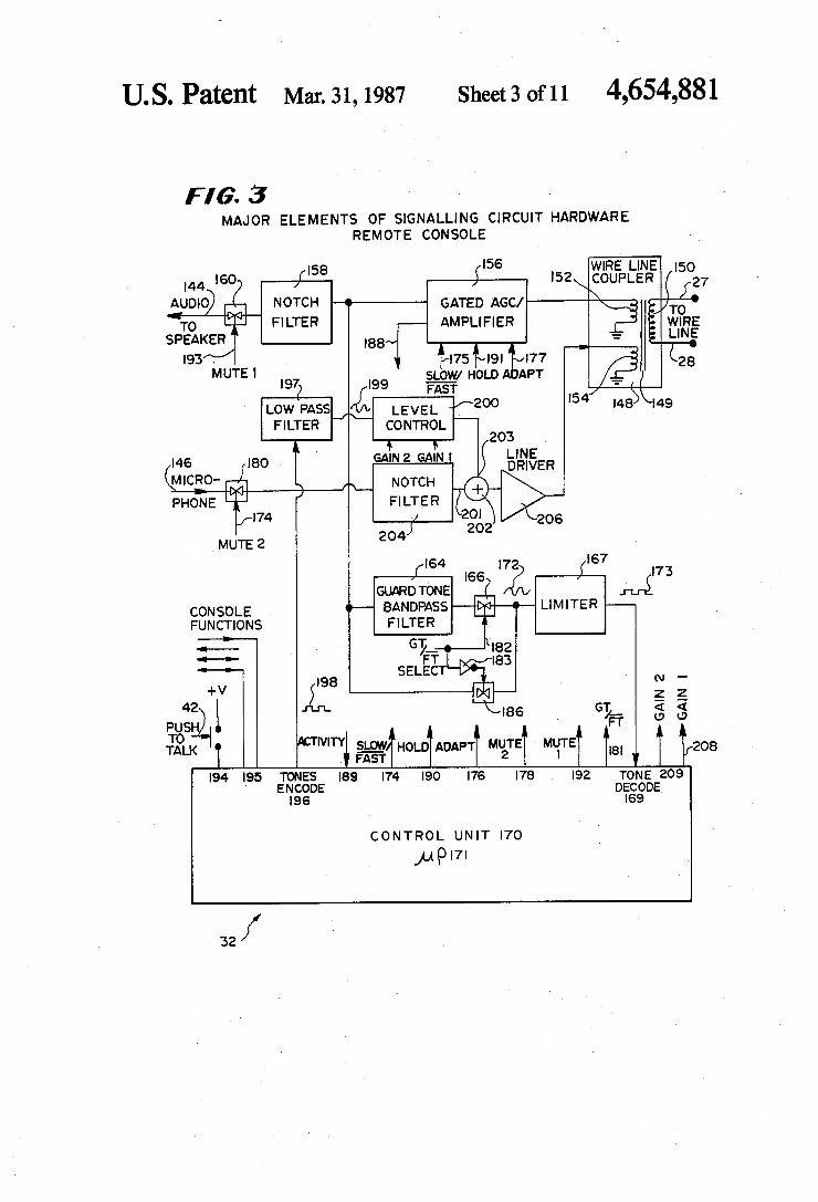
MAJOR ELEMENTS OF SIGNALLING CIRCUIT HARDWARE REMOTE CONSOLE
4,654,881
I58 '56 WIRE LINE I50 4 I60 f I l52\COUPLER 27
NoTcH -~———— GATED AGC/ \ To
FILTER AMPLIFIER ? ’ wIRE I88 = LINE
I93 . $r|75[‘~|9l?v|77 Z MuTEI 28 SLOW/ HOLD ADAPT I97) 199 ‘F?- ? I /
Low‘PAssJé LEVEL -/‘2°° '54 I485\l49 FILTER CONTROL
1} GAINZ GAIN!
NOTCH FILTER
/
204} 202
I64 I67 f '66 '72 { I73
GUDRDTONE m-é CONSOLE 0- BANDPASS LIMITER FUNCTIONS FILTER ___..>— <—_ <—> ‘—>—
W I98 2 g 42 in - - |86 GT <1 4
qléSl-jl‘l - 437- o o 2 MM" SLOW MUTE MUTE
TALK &F_A_§/THOLDTADAPTT 2 1 I8| 208 I94 I95 TONES I89 I74 I90 176 we I92 TONE 209
ENCODE DECODE I96 I69 ’
CONTROL UNIT I70
mm
32/
U. S. Patent Mar. 31, 1987 Sheet 4 of 11 4,654,881
FIG‘. 4/ coNT-RoL UNIT DETAILS»
FROM T N LIMITER OSTEST
69 19 96
TONE PRESENT ——> —_I
DIGITAL I: EE§§§RE{_’ DIGITAL TONE :: DECODED _ TONE
DECODER GTENABLE ENCODE ENCODER FT ENABLE ENABLE 1
2'0) ,_l_\ k2m
MICRO-PROGRAMMED CONTROL CONTROL SEQUENCER '1 STORE
EPROM-\ WI @ W m
20/ SEQUENCER INPUTS: AcTIvITY
TONE PRESENT(4 LINES) TONE DECODER
SEQUENCER OUTPUTS: ADAPT GT ENABLE HOLD FT ENABLE
SLOW/FAST ENCODE ENABLE MUTE I, MUTE 2
GAIN I,GAIN 2 GT/FT SELECT
ENCODE FREQ-(4 LINES) STATION ,KEY
STATION FUNCTIONS, (64 LINES)
U.S. Patent Mar.3l,1987‘ SheetS ofll 4,654,881
22I 222 F l G- 5 § 223
PRIOR ART HLGT' ‘FT LLGT+VOICE SIMPLE STATION KEY'- 40 MSEC '__|5o MSEC
'20 MSEC a‘ DRoP0uT
220!’ FIG. 6'
226 227 $228 229
PIGGY-BACK STATION KEY‘. HLGT FT HLGT FT
230 _ 23I 232 233 234
MULTIPLE FUNCTION ToNES: HLGT é??l'il?ijiw LIMIT 235 242 (NEXT COMMAND)
LINE LooP TEST: CONSOLE HLgT HLG\T I 24IJ f243 I k245
BASE: -———T TEST TONE I004 Hz AT FT LEvEL(-I3cIbm) UNTIL 6 SECONDS OR HLGT
F IG 7 SIMPLE ACKNOWLEDGE $250 ._ ' LLGT(IF KEY COMMAND) SEQUENCE CONSOLEi —— HLGT FT
_ 253
BASE’. ‘USE-K1 252
VERIFIED ACKNOWLEDGE 1/250 25, 253 SEQUENCE; ' / __£_| LLGT [
CONSOLE'-—— HLGT FT 256 252
BASE: \_—V_-_/
SOLICITED ALARM 0R STATUS‘. _ {258 VAR'ABLE DURAT'ON 850 Hz
CONSQLE'--—— HLGT FT 259 26° 26I 262 263 264
BASE‘. HLGT ?l?l?? \ A
uNSoLIcITED ALARMS . ' _ SAME AS AB0vE ExcEPT BASE SENDS AUTOMATICAAL ‘IA/RM OR STAT‘US INFO 266x 267 268 269 270
HASP —— HLGT WT,‘
CONSOLE‘. LEADING STATuS MESSAGE: r27‘ 212 213 274 OEEIGOTNALWQICE
BASE: ————- HLGT ?f , r280
TRAILING STATuS MESSAGE: ‘ 281 282 283
BASE’- -- voIcE HLGT?l?]
OPTION
U. S. Patent Mar. 31, 1987 Sheet 6 ofll 4,654,881
F I6‘. 8
FuNcT|0N TONES USED=
W8? ‘2%??8?“ USE F0 2175 Hz HIGH LEVEL/LOW LEVEL GUARD TONE
F1 2050 Hz STANDARD FUNCTION TONE
F2 I950 Hz " " " ‘
F3 ' I850 Hz " " j "
F4 I750 Hz " " "/DATA TONE 000
F5 I650 Hz " " "/DA'TA TONE 00|
F6 I550 Hz " " "/ DATA TONE 0|0
F7 I450 Hz " ) " "/ DATA TONE on
F8 1350 Hz " " "/ DATA TONE I00
F9 ‘1250 Hz " " "/DATA TONE |0|I
FIO n50 Hz " " "/ DATA TONE no
Fll I050 Hz " " "/ DATA TONE Ill
H2 950 Hz " " "IREPEAT T0NE/Acc TONE
H3 850 Hz " " "/wA|T TONE
FM 750 Hz " " "
F15 650 Hz " " "
US. Patent Mar.3l, 1987 Sheet7ofll 4,654,881
FIG. 9 EQUIVALENT cmcun' 3;‘
THRESHOLD COMPARATOR
" FAST ATTACK THRESHOLD
T° 3231 COMPARATORPZdb)
OUTPUT
4823 PHONE LINE 24
30' _ (AUDIO m) 21302
FIG. 10 3 43 356 T 4
coHsoLg HIGH LEvEL FT ‘ A ‘AIL: VQ'CE LLGT GUARD TONE m ’ Y Y Y Y END OF T To: m: '
BASE STATION ‘imb’z’?kgw v12?‘ | PTT ' I - I
350 ' TEND OF ACK HI GH 35'- l ~ 360 l
GATE l - f ,
L°W ADAPT . . DROPPED
HIGH 352 I I , OUT
GATE 2 | I I Low SLOW/FAST. . ' --—
HIGH I
Low ACTIVITY , 353 l T5 .
l
I GATE 4 '
Lowl HOLD 7, T2 1-4 T6

U. S. Patent Mar. 31, 1987
FIG. ",4
SENDER OF MESSAGE:
Sheet 8 of 11 4,654,881
ALL OTHER NODES:
SEND MESSAGE
STEP IA
> SEND HLGT
FOR STEP 2A I20 M SEC
STEP 3A
SEND NEXT FUNCTION TONE
FOR 40 M SEC
HLGT DETECTED ‘
STEP 2B
STEP 1B
ENABLE HLGT DECODER
L——-_.
H LGT DECODED ?
DISABLE HLGT DECODER
ENABLE FUNCTION TONE DECODER
STEP 3B
STEP 4B
FUNCTII TONE REQ '
? YES YES
STEP 6B
CANCEL MESSAGE
LOOK UP COMMAND LIST GO TO
STEP 78 FOR THIS TONE
STEP 8B
US. Patent Mar.3l,1987_ Sheet9ofll 4,654,881
, I FIG’ [,3 STEP IOB
DISABLE
_STEP 9B FUNCTION
RE- PRIME “3N5 TIMER FoR DECVDER
l (FIG. IIA) FUNCTION
(6 WINDOW
STEP 5A STEP IIB
STEP 6A ENABLE 1 STEP I2B YES
FUWNOCTION 3%? NE DECODER TONE TURN ON.
—— - WAIT TONE
.l . NO STEP 8A STEP ‘M I ‘
STEP I38 EXECUTE COMMANDS
YES Assoc. WITH _ V TONES
STEP 9A STEP IOA v I RECEIVED
M ESSAGE RETRIGGER -
ERRoR TIME OUT STEP 14B RE-TRY wmDow
! STEP NA |
US. Patent Mar.3l, 1987_ Sheet 10 0f11 4,654,881
F16‘. nc {STEP I78 ERROR; SHUTOFFWAIT TONE,RECOVER AND RESTART
[fgTEhFmm/a) ' STEP I88
IS m TONE ON 1*
STEP BA \ EETFEP ‘9B INDICATE | ACC_ succEss Tom; , 55'” 4° '|*_ SEC
To’ RECVD' ACKNOW EDGE USER mus
l l .
(FIG. IIA) STEP 208 IS
THIS A "KEY'COMMAND
'? l .
YE STEP |7A _ 5
RETURN ENABLE STEP 2IB I TO ' LOW-LEVEL ENABLE
356'“ GUARENBONE LOW-LEVEL (F16. IIA) VOICE AUDIO I GugeRgogggE
so avxaswsm STEP 2a STEP To RECEIVE laA (FIG. HA)
I
STEP ISA
REMOVE um
(FIGJIA) AND MUTE BEGIN Aumo l
‘______l V v
U. S. Patent Mar. 31, 1987 Sheet 11 0111 4,654,881 ’ 1
F I G. I ID
NOTE‘- HIGH PRIORITY STEP 24B MESSAGE COULD BE ENABLE SENT HERE usms THE oEcooER’S’ HIGH LEVEL HLGT DECoDER GUARD TONE cAPTuRE FOR IOOMSEC FEATURE. SIMPLY SEND ' MESSAGE ANY TIME AFTER T, LLGT |S DROPPED. STEP 25B
HLGT ‘YES - DECODED
? N0 STEP 27B
STEP - FALSE YES ALARM RESUME’
LLGT 1
NA 7 E FTBLE STEP 28B
DECODER
STEP 29a
TRA3§MTTE¥ER STEP 3'8
éyFlauA-y PROCESS NEW COMMAND)
. 1
DE-KEY TRANSMITTER STEP 329
GO TO" BEGIN (FIG. HA)

4,654,881 1
REMOTE CONTROL SYSTEM HAVING SYMMETRICAL TONE, SEND/RECEIVE SIGNALING CIRCUITS FOR RADIO
COMMUNICATIONS
CROSS REFERENCE TO RELATED APPLICATIONS
This application is related to U.S. patent application Ser. No. 412,628 ?led on Aug. 30, 1982 and entitled: MULTIPLE SIMULTANEOUS TONE DECODER, U.S. patent application Ser. No. 448,457 ?led on Dec. 10, 1982 and entitled: GUARD TONE CAPTURE METHOD and U.S. patent application Ser. No. 487,490 ?led on Apr. 22, 1983 and entitled: PAGING UNI VERSAL REMOTE CONTROL ENCODER.
BACKGROUND OF THE INVENTION
1. Field of the Invention The present invention relates to a tone and voice
shared remote control system for radio communications and more particularly to a symmetrical signaling circuit in each unit of the remote control system for controlling the operation of one or more additional units of the system, all of which are coupled to a single audio chan nel. The invention also relates to an automatic gain control circuit utilized in each signaling circuit.
2. Description of the Prior Art Heretofore, various remote control systems for en
abling a remote console to control a base station cou pled to a transmitter and receiver have been proposed. Examples of several of these systems are disclosed in the following U.S. patents:
U.S. Pat. No. PATENTEE
3,577,080 Cannalte 4,184,118 Cannalte etal 4,208,631 Beseke et al
The system for remote control of a base station dis closed in U.S. Pat. No. 3,577,080 utilizes tone controls which are supplied over wire lines. A variety of differ ent tone controls can be generated and transmitted over the wire lines to control various functions of the base station. This system is limited by the fact that signaling is initiated strictly from the remote control console (point of control) for commanding the execution of functions at the base station. The base station feedback reporting system disclosed
in U.S. Pat. No. 4,184,118 is an improvement over the previous remote control system and includes a tone control system that allows for acknowledgement from the base station of the function command received from the remote console. In this way system reliability is improved by indicating functional line interconnection and communication by the remote console with the base station.
U.S. Pat. No. 4,208,631 discloses a digital pulsed DC remote control system. This system utilizes digital pulsed DC signaling to select a radio channel of a base station transmitter for transmission of a message and does not utilize tones as does the system of the present invention. There has also been proposed in U.S. Pat. No.
4,209,131 a computer-controlled irrigation system where remote sensors and ?uid delivery systems are
20
25
30
35
45
50
55
60
65
2 controlled by a central control station having a com puter and interface circuits.
In the systems disclosed in the patents referred to above, the number of tone command functions is greatly limited. Furthermore, function commands are restricted to tone transmission from the control point to the base station and not vice versa. -
Still further, the protocol in these prior systems for data transfer is not expandable and incapable of trans ferring great amounts of data information between the remote consoles and base stations. Moreover, in the systems disclosed in the Cannalte
patents, the signaling times are ?xed. In particular, the windows for function tones can be opened for ?xed periods of time to receive one or more function tones. This situation fosters low reliability due to falsing from noise signals or voice signals. Additionally, there exists no method in these prior systems for a remote console to determine the latched state of a base station without initiating a function change to a given known state.
Furthermore, in these prior systems there is no mech anism for a base station to initiate an unsolicited data transmission or an interrupt alarm signal or a status signal to a remote console.
Also, in the prior systems, multiple remote consoles and multiple base stations cannot be accomodated or coupled to a common audio channel or wire line while still maintaining uniform positive system integrity, knowledge of system state by all remote consoles and base stations and inherent muting of data sequences on parallel control positions. As will be described in greater detail hereinafter, the
remote control system having voice shared, tone, sym metrical, signaling circuits for radio communications of the present invention differs from the previously pro posed systems by including one or more remote con soles and/or one or more base stations coupled to a single common wire line/audio channel. Each base station and remote console having a symmetrical signal ing circuit with a plurality of modes of operation that provide inherent self-diagnostic capability and potential interface to external sources of digital data. ' Moreover, in the systems of the present invention,
gated sequential tone signaling is time multiplexed and compatible with the audio information to be transferred between units, whether they be base stations and/or remote consoles.
In addition, priority or preference in initiation of signaling over the audio channel or wire line is possible by any remote console or base station. All other units of base stations or remote consoles are responsive to this initiation of signaling in a well de?ned and predeter mined manner by the alteration of internal status states within the control unit of each signaling circuit and possibly by the participating in the data exchange by acknowledge or reply from a receiving signaling cir cuit.
Still further, the signaling protocol utilized is highly structured to permit a high degree of ?exibility and expansion in data interchanges while necessitating mini .mum degradation in basic system performance such as by the introduction of any delay or interference of nor mal voice transmission.
SUMMARY OF THE INVENTION
According to the invention there is provided a method for sending and receiving signals in a remote . control system having symmetrical signaling circuits
4,654,881 3
for radio communications, comprising the steps of: cou pling at least two units to an audio channel; monitoring in each unit the receipt of a high level guard tone; blocking audio inputs or outputs to or from said unit when a high level guard tone has been picked up from the audio channel; decoding the high level guard tone; decoding any commands encoded in function tones following the high level guard tone; and executing the commands.
Also, according to the invention there is provided a voice shared, tone, remote control system having sv etrical signaling circuits for radio counica
_ tions comprising: an audio channel, ?rst and second units coupled to said audio channel, each unit having means for sending a tone encoded signal, means for receiving a tone encoded signal; means for controlling the sending and receiving of signals; and means for acknowledging receipt of a signal.
Further, according to the invention there is provided a signaling circuit adapted to be coupled to an audio channel, to an audio output line, and to an audio input line and comprising: means for sensing a guard tone signal on the audio channel and for capturing the guard tone signal, means for blocking any audio output or audio input on the audio input or audio output line until the guard tone and subsequent function tone or tones are decoded, means for decoding the guard tone and any subsequent function tones, and means responsive to
" it the decoded function tones for coupling a voice signal following the function tones to the audio output line or for causing some other command to be executed.
Still further, according to the invention there is pro vided for use in a remote control system for radio com munications, a voice shared, tone send/receive signal ing circuit comprising audio channel coupling means for sending signals to and receiving signals from an audio channel coupled thereto, signal coupling means for coupling an output of said audio channel coupling
> . means to an audio output line, audio signal transmission means having an input adapted to be coupled to an .audio input line and an output coupled to said audio
channel coupling means, and control in for ing rived signals, for encoding transmitted s for controlling the send and receive signal transsions
into and out of said :uzr: g circuit, said control »:-r.r:~~ being coupled to the output of said signal couplin means and to said audio signal transmission means, and being operable to decipher coded signals associated with analog voice signals received by said audio chan nel coupling means and for supplying an encoded signal to said audio signal transmission means to be added to an audio signal supplied to said audio channel coupling means.
And still further, according to the invention there is provided in an automatic gain control circuit compris ing an operational ampli?er, the improvement compris ing: a voltage controlled resistor coupled between a minus input and the output of said operational plifier, a fixed resistor coupled between a si it‘. source d said
' us input of said 1:; plifier, d a plus input of d amplifier being coupled to a reference voltage VB.
‘With the remote control system of the present inven tion and the j. in; n: si 51v 1 I: g circuits utilized therein base stations and remote consoles all have equiv alent signaling capability. In this respect a base station can “KEY” other base stations or remote consoles and vice versa. The units of the system inherently stay in synchronization since all messages and acknowledge
llIlr i ll.
20
25
30
35
45
55
65
4 ments are monitored and decoded by all parallel con nected nodes consisting of one or more remote consoles and/or one or more base stations. The signaling circuits are programmed to receive
reverse alarm reports, unsolicited status reports and wait-for-free-channel reports as well as polled opera tion. Full cross muting of audio input and output lines to and from each signaling circuit is available during sig naling and during unsolicited alarms. ' Each unit, base station or remote console is capable of
positive, independent select/deselect of a parallel unit preventing loss of a unit by accidentally disabling it. This is useful for transmitter steering and for micro wave backbone systems. Audio and function tones are automatically muted during signaling of the other thereby eliminating annoying tones on the audio chan nel. Many signaling functions are proable via a
plurality of function tones which can be decoded into binary words. The protocol for operating the signaling circuits via a
microprocessor in each signaling circuit permits up ward compatible signaling using standard TRC func tion tones. However, messages are of free format and variable length allowing for fast response to KEY com
ds, yet for slower response for lower priority data commands. An extended message sequence is possible without
prolonging system key-up. The protocol provides for dual stage acknowledge
for indication of message receipt and of function suc cessfully completed. The protocol can handle beginning or trailing status
messages in any direction and constant update of cur rent station parameters, such as the current transmitting channel while maintaining data tone muting. Also, ad vanced diagnostic capability is provided whereby entire station status can be called up by and received by a console for system diagnosis. Moreover, the function tone decode windows pro
vided are adaptable for various message length to ‘ ' e falsing from noise or voice, yet allowing ‘11.1..
length Sim/1. .
BF DESCRIPTION OF THE DRAGS
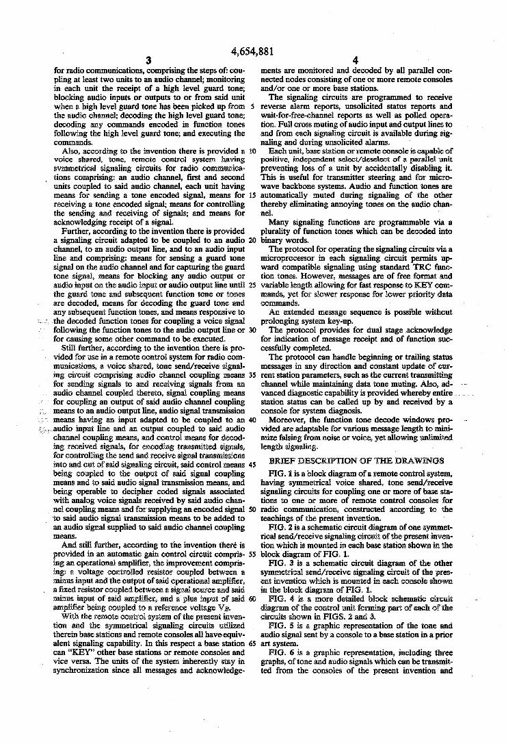
FIG. 1 is a block diagram of a remote control system, having symmetrical voice shared, tone send/receive signaling circuits for coupling one or more of base sta tions to one or more of remote control consoles for radio communication, constructed according to th teachings of the present invention. ' FIG. 2 is a schematic circuit diagram of one s -
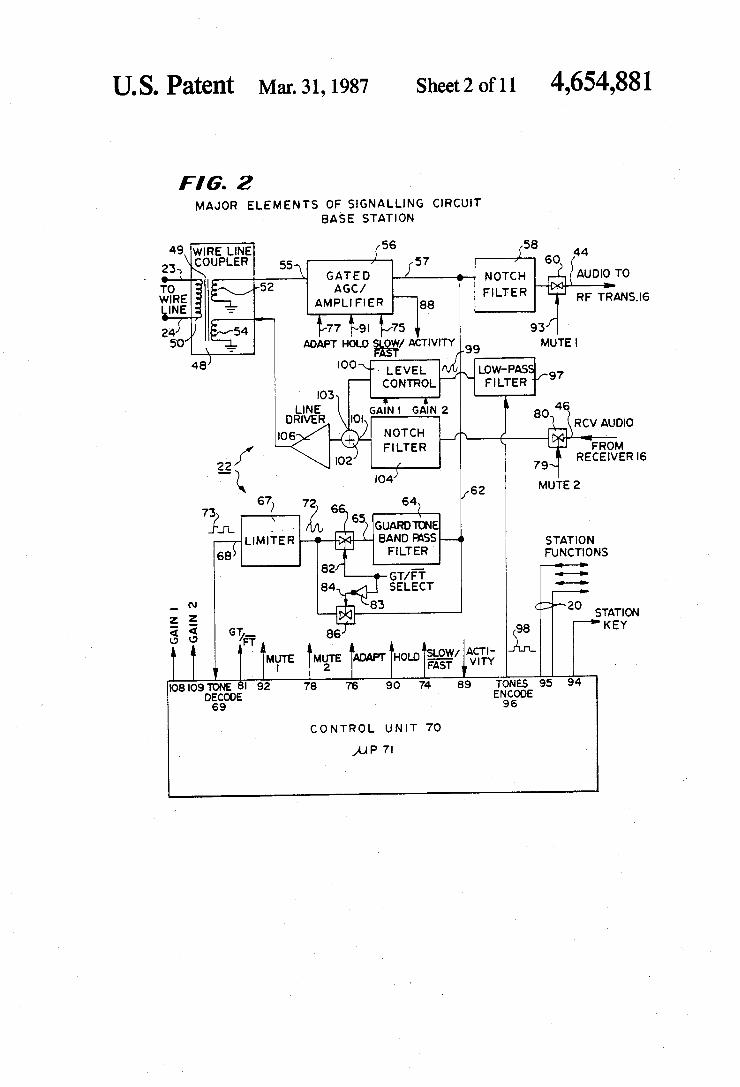
rical send/receive signaling circuit of the present inven tion which is mounted in each base station shown in the block diagram of FIG. 1. FIG. 3 is a schematic circuit diagram of the other
setrical send/receive signaling circuit of the pres ent invention which is mounted in each cole shown in the block diagram of FIG. 1. FIG. 4 is a more detailed block n. in circuit
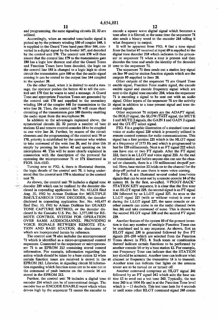
diagr of the control unit Urn. Jig part of each of the circuits shown in FIGS. 2 and 3. FIG. 5 is a graphic representation of the tone and
audio signal sent by a console to a base station in a prior art system. FIG. 6 is a graphic representation, including three
graphs, of tone and audio signals which can be transmit ted from the consoles of the present invention and

5 shows in the third graph, a command signal from a console overriding a test tone being emitted by a base station. FIG. 7 is a graphic representation, including six
graphs, of command signals emitted by a console rela tive to signals sent from the base station for six different modes of operation of the system of the present inven tion. FIG. 8 is a table of the Function Tones that can be
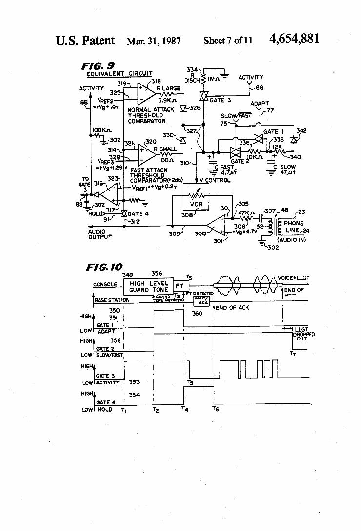
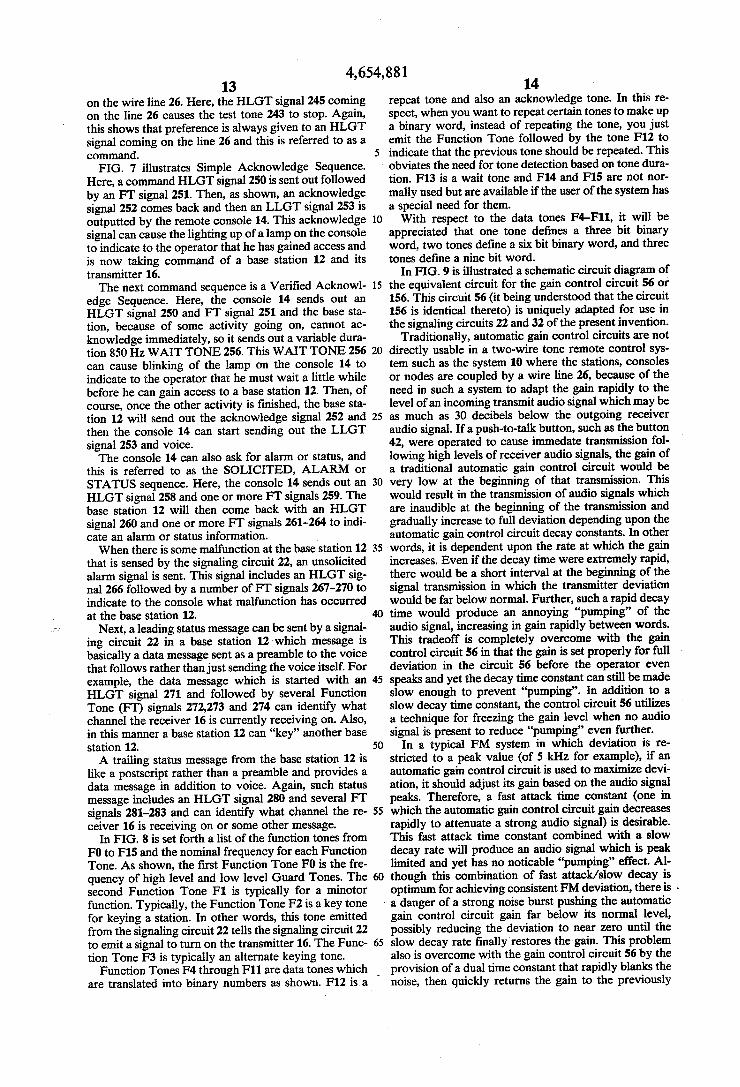
utilized by the system of the present invention. FIG. 9 is a schematic circuit diagram of the automatic
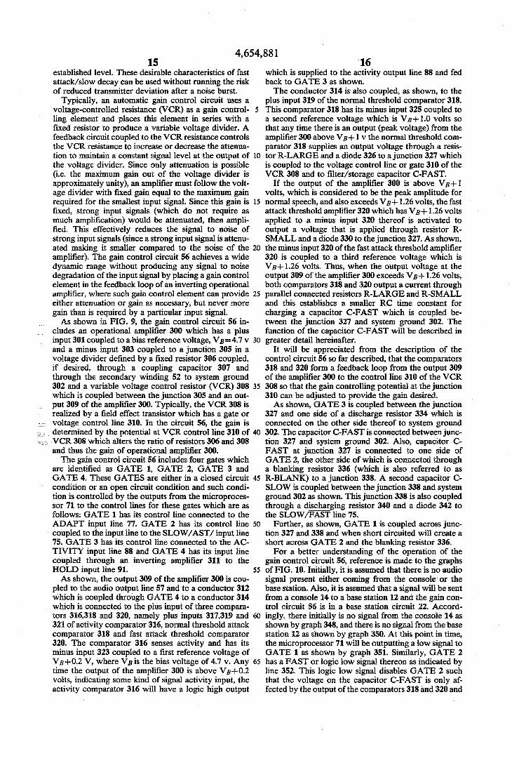
gain control circuit utilized in each of the circuits shown in FIGS. 2 and 3. FIG. 10 is a group of ?ve graphs showing the various
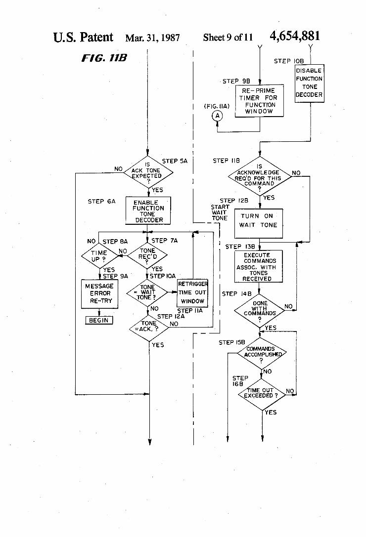
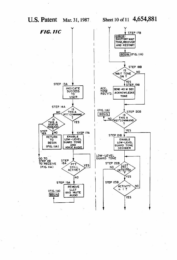
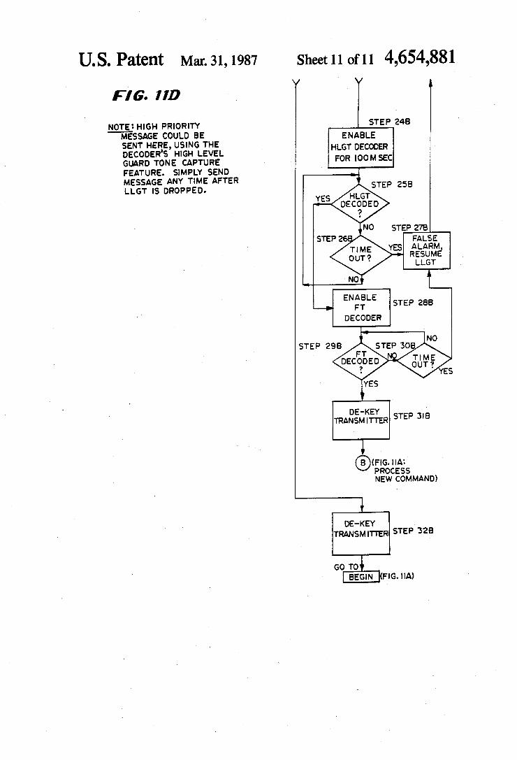
signal levels at different points and times in the auto matic gain control circuit shown in FIG. 9. FIGS. 11A-11D‘together comprise a flow chart of
the protocols followed by the microprocessor of the control unit for either sending a message or for receiv ing a message from any other console or base station with the ?ow chart or protocol on the left-hand side setting forth the steps followed for sending a message and the flow chart or protocol on the right-hand side showing the steps followed for receiving a message.
DESCRIPTION OF THE PREFERRED EMBODIMENTS
Referring now to FIG. 1, there is illustrated therein a block diagram of the remote control system for radio communications constructed according to the teachings of the present invention. The remote control system is generally identi?ed by reference numeral 10 as shown. The system 10 includes one or more base stations 12, three of which are shown numbered 1, 2 and N and/or one or more remote control consoles 14 three of which are shown and numbered 1, 2 and M. Each of the base stations 12 includes conventional
radio transmitter and receiver circuitry generally identi ?ed by the reference numeral 16. This radio transmitter and receiving circuitry 16 includes an output/input 17 coupled to an antenna 18 and is coupled by multiple lines 20 in the base station 12 to a voice-shared, tone send/receive signaling circuit 22. The signaling circuit 22 is coupled by two conductors
23, 24 to a conventional wire line, or audio channel 26. The wire line 26 is a standard audio communications channel, typically a standard telephone line or so-called “twisted pair” or its equivalent. Other possible channels such as a microwave link, ?ber-optic link or a radio relay link can be used in place of the wire line 26. Such wire line 26 must be capable of passing electrical signals over a nominal frequency band width of from 300 Hz to 3000 Hz in a full duplex fashion. The function of the wire line 26 is to electrically connect each base station 12 to all the other base stations 12 and consoles 14 cou pled to the wire line 26. Other possible audio channels, such as a 4-wire duplex channel, can be utilized for electrically connecting the stations 12 and consoles 14 in parallel. As shown, the wire line 26 is connected to a pair of
input/ output lines 27 and 28 coupled to each console 14. More speci?cally, the lines 27 and 28 are coupled to a symmetrical, voice-shared, tone send/receive signaling circuit 32 in each console 14. Such signaling circuit 32 is symmetrical and substantially identical to the signaling circuit 22. The signaling circuit 32 is coupled by a plu rality of lines 34 to console hardware and associated circuitry 36. This console hardware and associated cir
4,654,881‘
20
25
35
40
45
55
60
65
6 cuitry 36 interfaces the signaling circuit 32 with a speaker 38, a microphone 40, a microphone activating push button switch 42 and other devices such as control lights. The base stations 12 including the radio transmitter
and receiver 16 is typically situated at a point of high elevation such as on a hill, mountain or the top of a building to provide effective transmission of signals radiated from an elevated height. However, it is gener ally not desired to have an operator at the site of the transmitter and therefore, the operation of the transmit ter/receiver 16 is controlled from a remote control console 14 located, for example, in a police station. The system 10 of the present invention is particularly
adapted for coupling more than one base station 12 to more than one remote control console 14 over a con ventional audio channel, such as telephone wire line 26 utilizing tone control signals which are shared by the audio/voice signals on the wire line 26. In this respect, coded tones and audio/voice signals are carried by the wire line 26 from a base station to a remote control console or vice versa. In particular, the wire line 26 couples a remote control console 14 to a base station 12 when the console 14 wishes to communicate, via that base station’s transmitter/receiver 16, with a mobile unit, such as a policecar or another system such as uti lized by the state police or the sheriff’s police. The system 10 of thepresent invention is able to
provide multiple coupling of base stations 12 and con soles 14 as shown in FIG. 1 by utilizing symmetrical send/receive signaling circuits 22 and 32 and by reason of the programming of microprocessors in the signaling circuits 22 and 32 which in conjunction with operator manual activation, enable communication between one console 14 and a selected other console 14 or base sta tion 12. Additionally, the symmetrical signaling circuits 22 and 32 together with the programmed microproces sor in each circuit 22 or 32 enables an operator of a particular console 14 to gain control of the communica tion channel-wire line 26 for transmitting information,
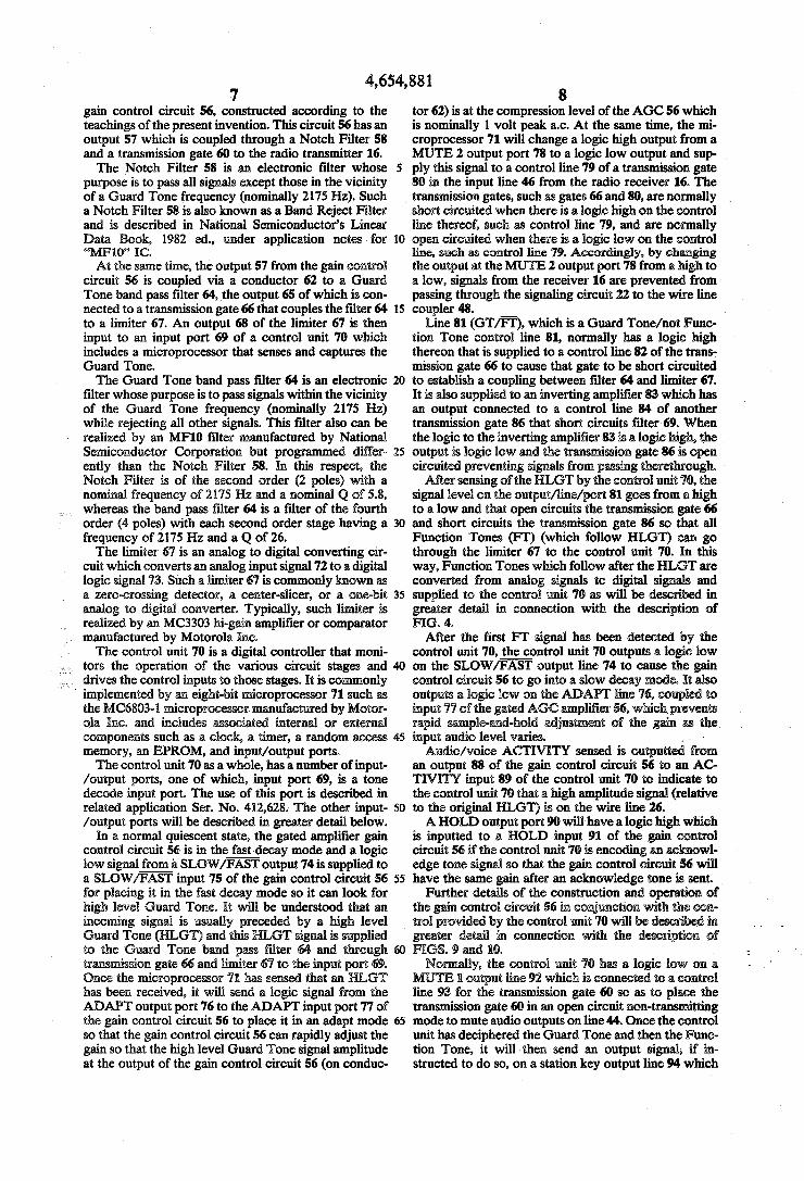
. including coded signals and/or audio/voice signals. Referring now to FIG. 2, there is illustrated therein,
a schematic circuit diagram of the signaling circuit 22 showing the major hardware elements thereof. Here, it will be seen that audio output signals to the radio trans mitter/receiver 16 are supplied on an output line 44 and signals that are picked up from the antenna 18 and am pli?ed by the receiver 16 are inputted to the circuit 22 on an input line 46.
It is to be understood that the sending of signals takes preference over the receiving of signals. In this respect, signals sent from a console 14 will include coded tone signals and audio/voice signals and will be received at the input lines 23, 24 and supplied to a wire line coupler 48. The coupler 48 includes a transformer 49 having a primary input winding 50, a secondary output winding 52 and a secondary input winding 54 by which signals received from the transmitter 16 are supplied to the wire line 26 as will be described in greater detail herein after. The wire line coupler 48 is a standard coupling trans
former 49 commonly used to interface a balanced 600 ohm wire line 26 to an unbalanced signal. A signal received from a console and supplied to the
primary winding 50 is picked up by the secondary wind ing 52 which functions as a monitor of the wire line 26 for signals thereon and supplies that signal to an input 55 of a gated automatic gain control ampli?er, or simply
4,654,881 7
gain control circuit 56, constructed according to the teachings of the present invention. This circuit 56 has an output 57 which is coupled through a Notch Filter 58 and a transmission gate 60 to the radio transmitter 16. The Notch Filter 58 is an electronic ?lter whose
purpose is to pass all signals except those in the vicinity of a Guard Tone frequency (nominally 2175 Hz). Such a Notch Filter 58 is also known as a Band Reject Filter and is described in National Semiconductor's Linear Data Book, 1982 ed., under application notes for 6‘ll/11:10” 1C. At the same time, the output 57 from the gain control
circuit 56 is coupled via a conductor 62 to a Guard Tone band pass ?lter 64, the output 65 of which is con nected to a transmission gate 66 that couples the ?lter 64 to a limiter 67. An output 68 of the limiter 67 is then input to an input port 69 of a control unit 70 which includes a microprocessor that senses and captures the Guard Tone. The Guard Tone band pass ?lter 64 is an electronic
?lter whose purpose is to pass signals within the vicinity of the Guard Tone frequency (nominally 2175 Hz) while rejecting all other signals. This ?lter also can be realized by an MF10 ?lter manufactured by National Semiconductor Corporation but programmed differ ently than the Notch Filter 58. In this respect, the Notch Filter is of the second order (2 poles) with a nominal frequency of 2175 Hz and a nominal Q of 5.8,
/ whereas the band pass ?lter 64 is a ?lter of the fourth order (4 poles) with each second order stage having a frequency of 2175 Hz and a Q of 26. The limiter 67 is an analog to digital converting cir
cuit which converts an analog input signal 72 to a digital logic signal 73. Such a limiter 67 is commonly known as a zero-crossing detector, a center-slicer, or a one=bit analog to digital converter. Typically, such limiter is realized by an MC3303 hi-gain ampli?er or comparator manufactured by Motorola Inc. The control unit 70 is a digital controller that moni
tors the operation of the various circuit stages and w‘ l ' drives the control inputs to those stages. It is coonly
implemented by an eight=bit microprocessor 71 such as the MC6803=1 microprocessor. manufactured by Motor= ola Inc. and includes associated internal or external components such as a clock, a timer, a random ss memory, an EPROM, and input/output ports. The control unit 70 as a whole, has a number of input
/output ports, one of which, input port 69, is a tone decode input port. The use of this port is described in related application Ser. No. 412,628. The other input /output ports will be described in greater detail below.
In a normal quiescent state, the gated ampli?er gain control circuit 56 is in the fast decay mode and a logic low signal from a SLOW/FAST output 74 is supplied to a SLOW/FAST input 75 of the gain control circuit 56 for placing it in the fast decay mode so it can look for high level Guard Tone. It will be understood t an incoming signal is usually preceded by a high level Guard Tone (HLGT) and this HLGT signal is supplied to the Guard Tone band pass ?lter 64 and through transmission gate 66 and in ter 67 to the input port 69. Once the microprocessor ‘71 has sensed that an HLGT has been received, it will send a logic signal from the ADAPT output port 76 to the ADAPT input port 77 of the gain control circuit 56 to place it in an adapt mode so that the gain control circuit 56 can rapidly adjust the gain so that the high level Guard Tone signal amplitude at the output of the gain control circuit 56 (on conduc
5
25
30
35
40
45
65
8 tor 62) is at the compression level of the AGC 56 which is nominally 1 volt peak a.c. At the same time, the mi croprocessor 71 will change a logic high output from a MUTE 2 output port 78 to a logic low output and sup ply this signal to a control line 79 of a transmission gate 80 in the input line 46 from the radio receiver 16. The transmission gates, such as gates 66 and 80, are normally short circuited when there is a logic high on the control line thereof, such as control line 79, and are normally open circuited when there is a logic low on the control line, such as control line 79. Accordingly, by changing the output at the MUTE 2 output port 78 from a high to a low, signals from the receiver 16 are prevented from passing through the signaling circuit 22 to the wire line coupler 48. ___
Line 81 (GT/Fl‘), which is a Guard Tone/not Func tion Tone control line 81, normally has a logic high thereon that is supplied to a control line 82 of the trans: mission gate 66 to cause that gate to .be short circuited to'establish a coupling between ?lter 64 and limiter 67. It is also supplied to an inverting ampli?er 83 which has an output connected to a control line 84 of another transmission gate 86 that short circuits ?lter 69. When the logic to the inverting ampli?er 83 is a logic high, the _ output is logic low and the transmission gate 86 is open circuited preventing signals from passing therethrough.
After sensing of the HLGT by the control unit 70, the signal level on the output/line/port 81 goes from a high to a low and that open circuits the transmission gate 66 and short circuits the transmission gate 86 so that all Function Tones (FT) (which follow HLGT) can go through the limiter 67 to the control unit 70. In this way, Function Tones which follow after the HLGT are converted from analog signals to digital si 1|? A; _ supplied to the control unit 70 as will be descri in greater detail in connection with the description of FIG. 4.
After the ?rst FT signal has been detected by the control unit 70, the control unit 70 outputs a logic low on the SLOW/FAST output line 74 to cause the gain control circuit 56 to go into a slow decay mode. It also outputs a logic low on the ADAPT line 76, coupled to input 77 of the gated AGC :=_ ru: 56, which prevents rapid ple-and=hold adjustment of the g as the input audio level varies. _ . '
Audio/voice ACTIVITY is outpu from an output 88 of the gain control circuit 56 to an AC TIVITY input 89 of the control unit 70 to indicate to the control unit 70 that a high amplitude signal (relative to the original HLGT) is on the wire line 26. A HOLD output port 90 will have a logic high which
is inputted to a HOLD input 91 of the gain control circuit 56 if the control unit 70 is encoding an acknowl edge tone signal so that the gain control circuit 56 will have the same gain after an acknowledge tone is sent. _
Further details of the construction and operation of the gain control circuit 56 in conjunction with the con- . trol provided by the control unit 70 will be 'w-i in greater de in connection with the description of FIGS. 9 d 10.
Normally, the control t '70 has a logic low on a MUTE ll output line 92 which is connected to a control line 93 for the transmission gate 60 so as to place the transmission gate 60 in an open circuit non=transmitting mode to mute audio outputs on line 44. Once the control unit has deciphered the Guard Tone and then the Func tion Tone, it will then send an output signal, if in structed to do so, on a station key output line 94 which

4,654,881 activates the transmitter to transmit a signal. At the same time, or a short predetermined time period there after, the logic signal level on the MUTE 1 output 92 is changed from a low to a high to place the transmission gate 60 in a closed circuit condition. Then, the audio/ voice signal received by the gain control circuit 56 is passed through the Notch Filter 58, which ?lters out the Guard Tone signals, and through the transmission gate 60 to the radio frequency transmitter 16. Depending upon the Function Tones received and
decoded by the control unit 70, various station func tions as well as keying of the station/transmitter 16 can be effected by the microprocessor 71. In this respect, a plurality of input/ output lines 95 are provided by which inputs from the transmitter/receiver 16 can be supplied to the microprocessor 71 for effecting certain opera tions.
In this respect, when a signal such as an audio/ voice signal from a mobile unit is picked up by the antenna 18 and supplied to the receiver 16, the receiver 16 supplies signals on the station function lines 95 t0 the control unit 70 to tell it that a signal is coming in from a mobile unit or other unit. The control unit 70 will then generate certain tone codes, as will be described in greater detail hereinafter in connection with the description of FIG. 4, which are outputted on a tone encode output line 96 to a low pass ?lter 97 which ?lters digital tone function signal 98 to produce ?ltered analog signal 99. The low pass ?lter 97 is an electronic ?lter that passes
all frequency components below a predetermined cut off frequency while rejecting those above that fre quency. Typically, this ?lter is a ?ve pole Tschebyshev ?lter with its nominal cut-off frequency at 2700 Hz. The analog signal 99 from the low pass ?lter 97 is
then supplied to a level control circuit 100 which is a programmable attenuator that is controlled by two control inputs GAIN 1 and GAIN 2. Based on the logic levels at these two inputs, GAIN 1 and GAIN 2, the level control circuit 100 assumes a GAIN as predeter mined by the circuit design. Table 1 below, shows how this is achieved:
TABLE 1 GAIN 1 GAIN 2 SETS GAIN 2:
LOW LOW —30 DB for low-level Guard Tone HIGH LOW — 10 DB for Function Tone LOW HIGH 0 DB for high-level Guard Tone HIGH HIGH unde?ned (not used)
The gain levels shown in Table l above are relative to the peak audio/voice levels that are present at an audio input 101 to an audio mixer stage 102. The mixer stage 102 is also coupled to the output of the level control circuit 100 and simply mixes (algebraically adds) the attenuated coded tones received at an input 103 from the level control circuit 100 and audio signals received at the input 101 from a Notch Filter 104. While the encoded tones are being supplied to the
?lter 97 and the level control circuit 100, the signal from the MUTE 2 output port 78 to the control line 79 is still a logic low to maintain the transmission gate 80 open circuited. Once the encoded signals have been output ted from the control unit 70, the signal level from the MUTE 2 output port 78 is changed to a logic high to close circuit the transmission gate 80 and allow the audio/voice signal on the input line 46 to pass through the transmission gate 80 to the Notch Filter 104, which is substantially identical to the Notch Filter 58. The Notch Filter 104 ?lters out audio energy in the vicinity
20
25
30
35
45
50
55
65
10 of the Guard Tone frequency and supplies a ?ltered audio signal to the input 101 of the mixer stage 102. The output from the mixer stage 102 is then supplied to a line driver 106 which drives winding 54 of wire line coupler 48 to place the encoded tone/audio signal onto the wire line 26. As shown in FIG. 2, the attenuation by the level
control circuit 100 is controlled by the logic levels on the two inputs GAIN 1 and GAIN 2, which logic inputs are supplied from GAIN 1 output port 108 and GAIN 2 output port 109 of the control unit 70.
It will be understood that when the transmission gate 80 is short circuited to receive audio signal from the receiver 16, a control signal to the control line 93 from the MUTE 1 output port 92 will be a logic low and is supplied to the transmission gate 60 to prevent any signals from being sent to the transmitter 16.
Also, the gain control circuit 56 will be in a fast decay mode at this point in time (since the base station is not in a “Line Push-to-Talk” mode). However, if a remote console 14 should output a coded signal, in other words, an HLGT signal, this HLGT signal will be received and modi?ed by the gain control circuit 56 and inputted to the tone decode input port 69 of the control unit 70. Once the control unit 70 receives such an HLGT signal, it will immediately change the logic signal supplied from the MUTE 2 output port 78 to the control line 79 of the transmission gate 80 to open circuit that transmis sion gate and interrupt the audio transmission from the receiver 16 to the wire line 26. In this way, priority of control of the symmetrical, voice-shared, tone, send /receive signaling circuit 22 is controlled by a sender of a signal from one of the consoles 14 or base stations 12. FIG. 3 is a schematic circuit diagram of the symmet
rical, voice-shared, tone, send/receive signaling circuit 32. This circuit 32 is called a symmetrical circuit be cause it is symmetrical to the signaling circuit 22 and vice versa. For all intents and purposes, the circuit 32 is identical to the circuit 22 and the circuit elements of the circuit 32 are identi?ed by reference numerals which are identical to the reference numerals used in FIG. 2 except with the number 100 added to each of them. Accordingly, in the circuit 32, an audio output line 144, similar to the audio output line 44 shown in FIG. 2, supplies an audio signal to the speaker 38 (instead of to antenna 18 as does the line 44).
Then, instead of having an input line 46 from a re ceiver, the circuit 32 has an input line 146 from the microphone 40. The ‘other circuit elements are identical such as, for example, the wire line coupler 148 is identi cal to the coupler 48, the gain control circuit 156 is identical to the gain control circuit 56, etc. The only other difference between the circuit 32 and
the circuit 22 is that the plurality of input/output lines 195, substantially identical to the input/output 95 in the circuit 22, are console function lines instead of station function lines. Also, instead of a station keying line 94 which outputs a signal to the transmitter 16, the circuit 32 has a microphone enable input line 194 which is operated by the push button switch 42 to tell the control unit 170 to initiate signaling tones to cause a base station 12 to “key” and then cause the transmission gate 180 to be short circuited. Again, all the circuit elements of the circuit 32 are identical to, or as stated previously, sym metrical to, the circuit elements in the circuit 22. This simpli?es construction of the base stations 12 and the remote consoles 14 since, except for some connections
4,654,881 11
and programming, the same signaling circuits 22, 32 are utilized.
Accordingly, when an encoded tone/audio signal is picked up by the primary winding 150 of coupler 148, it is supplied to the Guard Tone band pass ?lter 164, con verted to a digital signal by the limiter 167, and decoded by the control unit 170. The control unit 170 will then ensure that the control line 179 to the transmission gate 180 has a logic low thereon and after the Guard Tones and Function Tones have been decoded, the logic on the control line 193 is changed to a logic high to close circuit the transmission gate 160 so that the audio signal coming in can be routed to the output line 144 coupled to the speaker 38. On the other hand, when it is desired to send a mes
sage, the operator pushes the button 42 to tell the con trol unit 170 that he wants to send a message. A Guard Tone and appropriate Function Tones are generated by the control unit 170 and supplied to the secondary winding 154 of the coupler 148 for transmission to the wire line 26. Then, the control unit 70 will cause short circuiting of the transmission gate 180 thereby enabling the audio input from the microphone 90.
In addition to the advantages explained above, the symmetrical circuits 22, 32 permit a number of base stations 12 and remote control consoles 14 to be coupled to one wire line 26. Further, by reason of the circuit elements and the programming of the control unit 70 or 170, priority is established by the operator who wishes to take command of the wire line 26, and he does this simply by pressing his button 42 and speaking on his microphone 40. This will be more clearly explained in connection with the description of the protocol for operating the microprocessor 71 or 171 illustrated in FIGS. 11A-11D. ,
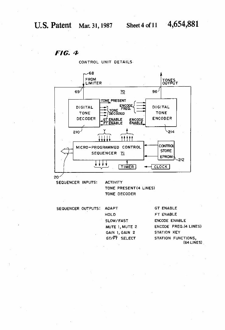
Turning now to FIG. 4, there is illustrated therein, the logic details of the control unit 70, it being under— stood that the control unit 170 is identical to the control unit 70. As shown, the control unit 70 includes a digital tone
7 ‘decoder 210 which can be realized by the decoder dis closed in copending application Ser. No. 412,628 ?led Aug. 30, 1982 by Arman Dolikian for: MULTIPLE SIMULTANEOUS TONE DECODER, the decoder disclosed in copending application Ser. No. 448,457 ?led Dec. 10, 1982 by Arman Dolikian for: GUARD TONE CAPTURE METHOD, or the decoder dis closed in the Cannalte US. Pat. No. 3,577,080 for RE MOTE CONTROL SYSTEM FOR OPERATION OVER SAME AUDIOCHANNEL PROVIDING VOICE SIGNALS BETWEEN REMOTE STA
20
25
35
40
45
50
TION AND BASE STATION, the disclosures ofv which are incorporated herein by reference. The control unit 70 also includes the microprocessor
71 which is identi?ed as a micro-programmed control sequencer. Connected to the sequencer or microproces sor 71 is an EPROM 212 containing stored control information. For example, information regarding the action which should be taken by a base station 12 when certain function tones are received is stored in the EPROM 212. Likewise, in signaling circuit 32 informa tion regarding which function tones are to be sent out at the command of push buttons on the console 16 are stored in the EPROM 212.
Further, the control unit 70 includes a digital tone encoder 214 which can be of conventional design. The encoder has an ENCODE ENABLE input which when driven high by the sequencer 71 causes the encoder to
65
12 encode a square wave digital signal which becomes a tone after it is ?ltered, at the same time the sequencer 71 also sends a binary word to the encoder 214 telling it what frequency to output.
It will be apparent from FIG. 4 that a tone signal from the limiter 67 received at input 69 is supplied to the digital tone decoder 210 which indicates to the proces sor or sequencer 71 when a tone is present and then decodes the tone and sends the identity of the decoded tone to the sequencer 71. The sequencer 71 then sends out a station key signal
on line 99 and/or station function signals which are the outputs 95 supplied to lines 20. Other outputs of the sequencer 71 are Guard Tone
enable signal, Function Tone enable signal, the encode enable signal and encode frequency signal which are sent to the digital tone encoder 214, when the sequencer 71 is encoding a signal to be sent out with an audio signal. Other inputs of the sequencer 71 are the activity signal in addition to a tone present signal and tone de coded signals.
Other sequencer 71 outputs are the ADAPT signal, the HOLD signal, the SLOW/FAST signal, the MUTE 1 and MUTE 2 signals, the GAIN 1 and GAIN 2 signals and the GT/? select signal. FIG. 5 is a graphic illustration of a standard tone and
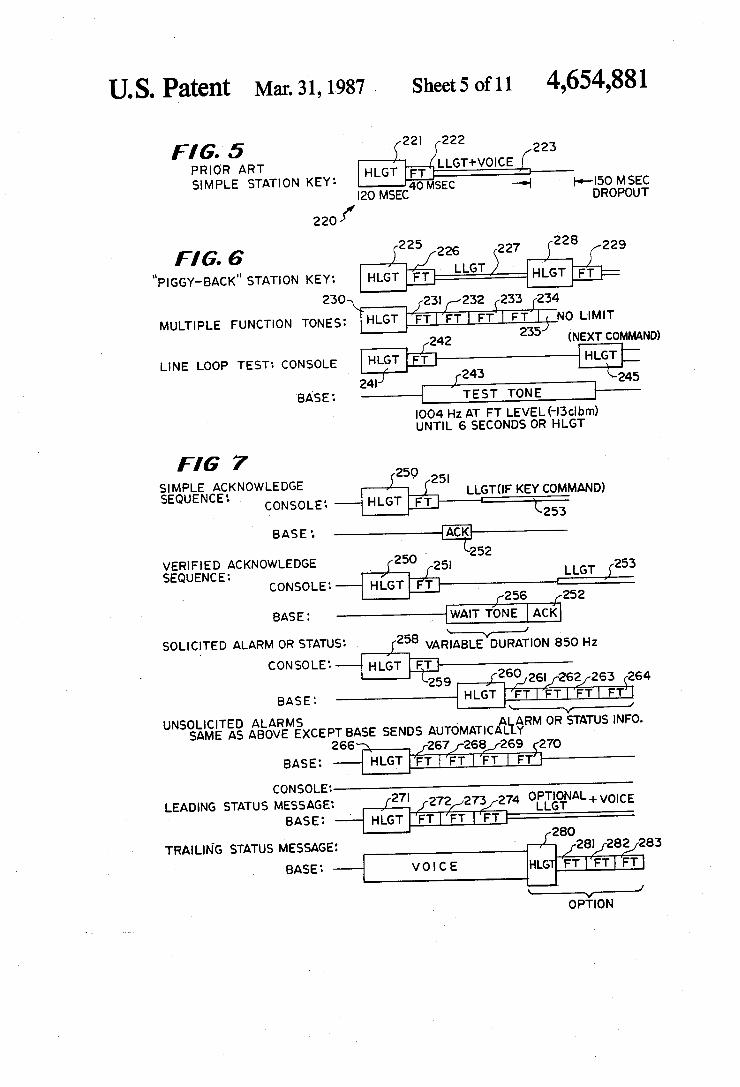
voice or audio signal 220 which is presently utilized in remote control systems for radio communications. This signal has a ?rst portion 221 which is the HLGT signal at a frequency of 2175 Hz and which is programmed to last for 120 milliseconds. Next is an FT signal 222 which can have one or two FT signals. After the F1‘ signal 222, there is an LLGT and voice signal 223. At the end of transmission and before anyone else can use the chan nel or channels, there is a 150 millisecond dropoff per iod. Here, base station 12 holds on to the channel for the drop-off period in case there is more voice coming.
In FIG. 6, are illustrated several coded tone/voice signals that can be sent out by a remote console 14 of the system 10. In the ?rst, so-called, '-FPIGGY-BACK” STATION KEY sequence, it is clear that the ?rst tone is an HLGT signal 225, the second signal is an FT signal 226 followed by an LLGT signal 227. As soon as the LLGT signal 227 (with or without voice) is over or during the LLGT signal 227, the same console or an= other console can come in on the audio channel (wire line 26) and take command of same. This is shown by the second HLGT signal 228 and the second FT signal 229. Another feature of the system 10 of the present inven
tion is that any number of multiple Function Tones can be combined and in any sequence. As shown, ?rst an HLGT signal 230 is generated followed by ?ve FT signals 231-235 which are selected from the Function Tones shown in FIG. 8. Such tones or combination thereof indicate certain functions to be performed by another console 14 or by a base station 12. For example, one Frequency Tone can indicate that the STATION key should be actuated. Another tone can indicate what channel or frequency the transmitter 16 is to transmit. Another tone can indicate that lights on the antenna tower are to be turned on or turned off. Another command comprises an HLGT signal 241
followed by an FT signal 242 which asks the base sta tion 12 to send out a test tone 243. Typically, the test tone 243 is at 1004 Hz and is at the Function Tone level which is -— 13 decibels. This test tone lasts for 6 seconds or until some other HLGT command signal 245 comes
4,654,881 13
on the wire line 26. Here, the HLGT signal 245 coming on the line 26 causes the test tone 243 to stop. Again, this shows that preference is always given to an HLGT signal coming on the line 26 and this is referred to as a command. FIG. 7 illustrates Simple Acknowledge Sequence.
Here, a command HLGT signal 250 is sent out followed by an FT signal 251. Then, as shown, an acknowledge signal 252 comes back and then an LLGT signal 253 is outputted by the remote console 14. This acknowledge signal can cause the lighting up of a lamp on the console to indicate to the operator that he has gained access and is now taking command of a base station 12 and its transmitter 16. The next command sequence is a Veri?ed Acknowl
edge Sequence. Here, the console 14 sends out an HLGT signal 250 and FT signal 251 and the base sta tion, because of some activity going on, cannot ac knowledge immediately, so it sends out a variable dura tion 850 Hz WAIT TONE 256. This WAIT TONE 256 can cause blinking of the lamp on the console 14 to indicate to the operator that he must wait a little while before he can gain access to a base station 12. Then, of course, once the other activity is ?nished, the base sta tion 12 will send out the acknowledge signal 252 and then the console 14 can start sending out the LLGT signal 253 and voice. The console 14 can also ask for alarm or status, and
this is referred to as the SOLICITED, ALARM or STATUS sequence. Here, the console 14 sends out an HLGT signal 258 and one or more FT signals 259. The base station 12 will then come back with an HLGT signal 260 and one or more FT signals 261~264 to indi cate an alarm or status information. When there is some malfunction at the base station 12
that is sensed by the signaling circuit 22, an unsolicited alarm signal is sent. This signal includes an HLGT sig nal 266 followed by a number of FT signals 267-270 to indicate to the console what malfunction has occurred at the base station 12.
Next, a leading status message can be sent by a signal ing circuit 22 in a base station 12 which message is basically a data message sent as a preamble to the voice that follows rather than just sending the voice itself. For example, the data message which is started with an HLGT signal 271 and followed by several Function Tone (FT) signals 272,273 and 274 can identify what channel the receiver 16 is currently receiving on. Also, in this manner a base station 12 can “key” another base station 12. A trailing status message from the base station 12 is
like a postscript rather than a preamble and provides a data message in addition to voice. Again, such status message includes an HLGT signal 280 and several FT signals 281-283 and can identify what channel the re ceiver 16 is receiving on or some other message.
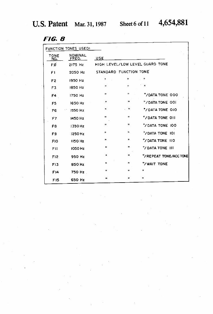
In FIG. 8 is set forth a list of the function tones from F0 to F15 and the nominal frequency for each Function Tone. As shown, the ?rst Function Tone F0 is the fre quency of high level and low level Guard Tones. The second Function Tone F1 is typically for a minotor function. Typically, the Function Tone F2 is a key tone for keying a station. In other words, this tone emitted from the signaling circuit 22 tells the signaling circuit 22 to emit a signal to turn on the transmitter 16. The Func tion Tone F3 is typically an alternate keying tone.
20
25
30
35
45
65
Function Tones F4 through F11 are data tones which _ are translated into binary numbers as shown. F12 is a
14 repeat tone and also an acknowledge tone. In this re spect, when you want to repeat certain tones to make up a binary word, instead of repeating the tone, you just emit the Function Tone followed by the tone F12 to indicate that the previous tone should be repeated. This obviates the need for tone detection based on tone dura tion. F13 is a wait tone and F14 and F15 are not nor mally used but are available if the user of the system has a special need for them. With respect to the data tones F4-F11, it will be
appreciated that one tone de?nes a three bit binary word, two tones de?ne a six bit binary word, and three tones de?ne a nine bit word.
In FIG. 9 is illustrated a schematic circuit diagram of the equivalent circuit for the gain control circuit 56 or 156. This circuit 56 (it being understood that the circuit 156 is identical thereto) is uniquely adapted for use in the signaling circuits 22 and 32 of the present invention.
Traditionally, automatic gain control circuits are not directly usable in a two-wire tone remote control sys tem such as the system 10 where the stations, consoles or nodes are coupled by a wire line 26, because of the need in such a system to adapt the gain rapidly to the level of an incoming transmit audio signal which may be as much as 30 decibels below the outgoing receiver audio signal. If a push-to-talk button, such as the button 42, were operated to cause immedate transmission fol lowing high levels of receiver audio signals, the gain of a traditional automatic gain control circuit would be very low at the beginning of that transmission. This would result in the transmission of audio signals which are inaudible at the beginning of the transmission and gradually increase to full deviation depending upon the automatic gain control circuit decay constants. In other words, it is dependent upon the rate at which the gain increases. Even if the decay time were extremely rapid, there would be a short interval at the beginning of the signal transmission in which the transmitter deviation would be far below normal. Further, such a rapid decay time would produce an annoying “pumping” of the audio signal, increasing in gain rapidly between words. This tradeoff is completely overcome with the gain control circuit 56 in that the gain is set properly for full deviation in the circuit 56 before the operator even speaks and yet the decay time constant can still be made slow enough to prevent “pumping”. In addition to a slow decay time constant, the control circuit 56 utilizes a technique for freezing the gain level when no audio signal is present to reduce “pumping” even further.
In a typical FM system in which deviation is re stricted to a peak value (of 5 kHz for example), if an automatic gain control circuit is used to maximize devi ation, it should adjust its gain based on the audio signal peaks. Therefore, a fast attack time constant (one in which the automatic gain control circuit gain decreases rapidly to attenuate a strong audio signal) is desirable. This fast attack time constant combined with a slow decay rate will produce an audio signal which is peak limited and yet has no noticable “pumping” effect. Al though this combination of fast attack/slow decay is optimum for achieving consistent FM deviation, there is ~ a danger of a strong noise burst pushing the automatic gain control circuit gain far below its normal level, possibly reducing the deviation to near zero until the slow decay rate ?nally restores the gain. This problem also is overcome with the gain control circuit 56 by the provision of a dual time constant that rapidly blanks the noise, then quickly returns the gain to the previously
4,654,881 15
established level. These desirable characteristics of fast attack/slow decay can be used without running the risk of reduced transmitter deviation after a noise burst.
Typically, an automatic gain control circuit uses a voltage-controlled resistance (VCR) as a gain control ling element and places this element in series with a ?xed resistor to produce a variable voltage divider. A feedback circuit coupled to the VCR resistance controls the VCR resistance to increase or decrease the attenua tion to maintain a constant signal level at the output of the voltage divider. Since only attenuation is possible (i.e. the maximum gain out of the voltage divider is approximately unity), an ampli?er must follow the volt age divider with ?xed gain equal to the maximum gain required for the smallest input signal. Since this gain is ?xed, strong input signals (which do not require as much ampli?cation) would be attenuated, then ampli ?ed. This effectively reduces the signal to noise of strong input signals (since a strong input signal is attenu ated making it smaller compared to the noise of the ampli?er). The gain control circuit 56 achieves a wide dynamic range without producing any signal to noise degradation of the input signal by placing a gain control element in the feedback loop of an inverting operational ampli?er, where such gain control element can provide either attenuation or gain as necessary, but never more gain than is required by a particular input signal. As shown in FIG. 9, the gain control circuit 56 in
cludes an operational ampli?er 300 which has a plus input 301 coupled to a bias reference voltage, 'VB=4.7 v and a minus input 303 coupled to a junction 305 in a voltage divider de?ned by a ?xed resistor 306 coupled, if desired, through a coupling capacitor 307 and through the secondary winding 52 to system ground 302 and a variable voltage control resistor (VCR) 308 which is coupled between the junction 305 and an out put 309 of the ampli?er 300. Typically, the VCR 308 is realized by a ?eld effect transistor which has a gate or voltage control line 310. In the circuit 56, the gain is determined by the potential at VCR control line 310 of VCR 308 which alters the ratio of resistors 306 and 308 and thus the gain of operational ampli?er 300. The gain control circuit 56 includes four gates which
are identi?ed as GATE 1, GATE 2, GATE 3 and GATE 4. These GATES are either in a closed circuit condition or an open circuit condition and such condi tion is controlled by the outputs from the microproces sor 71 to the control lines for these gates which are as follows: GATE 1 has its control line connected to the ADAPT input line '77. GATE 2 has its control line coupled to the input line to the SLOW/AST/ input line 75. GATE 3 has itscontrol line connected to the AC TIVITY input line 88 and GATE 4 has its input line coupled through an inverting ampli?er 311 to the HOLD input line 91. As shown, the output 309 of the ampli?er 300 is cou
pled to the audio output line 57 and to a conductor 312 which is coupled through GATE 4 to a conductor 314 which is connected to the plus input of three compara tors 316,318 and 320, namely plus inputs 317,319 and 321 of activity comparator 316, normal threshold attack comparator 318 and fast attack threshold comparator 320. The comparator 316 senses activity and has its minus input 323 coupled to a ?rst reference voltage of VB+0.2 V, where V]; is the bias voltage of 4.7 v. Any time the output of the ampli?er 300 is above V13+0.2 volts, indicating some kind of signal activity input, the activity comparator 316 will have a logic high output
20
25
45
55
60
65
‘16 which is supplied to the activity output line 88 and fed back to GATE 3 as shown. The conductor 314 is‘ also coupled, as shown, to the
plus input 319 of the normal threshold comparator 318. This comparator 318 has its minus input 325 coupled to a second reference voltage which is VB+l.0 volts so that any time there is an output (peak voltage) from the ampli?er 300 above Vg-i-l v the normal threshold com parator 318 supplies an output voltage through a resis tor R-LARGE and a diode 326 to a junction 327 which is coupled to the voltage control line or gate 310 of the VCR 308 and to ?lter/storage capacitor C-FAST.
If the output of the ampli?er 300 is above VB+1 volts, which is considered to be the peak amplitude for normal speech, and also exceeds VB+ 1.26 volts, the fast attack threshold ampli?er 320 which has V 5+ 1.26 volts applied to a minus input 320 thereof is activated to output a voltage that is applied through resistor R SMALL and a diode 330 to the junction 327. As shown, the minus input 320 of the fast attack threshold ampli?er 320 is coupled to a third reference voltage which is VB+ 1.26 volts. Thus, when the output voltage at the output 309 of the ampli?er 300 exceeds VB+ 1.26 volts, both comparators 318 and 320 output a current through parallel connected resistors R-LARGE and R-SMALL and this establishes a smaller RC time constant for charging a capacitor C-FAST which is coupled be tween the junction 327 and system ground 302. The function of the capacitor C-FAST will be described in greater detail hereinafter.
It will be appreciated from the description of the control circuit 56 so far described, that the comparators 318 and 320 form a feedback loop from the output 309 of the ampli?er 300 to the control line 310 of the VCR 308 so that the gain controlling potential at the junction 310 can be adjusted to provide the gain desired. As shown, GATE 3 is coupled between the junction
327 and one side of a discharge resistor 334 which is connected on the other side thereof to system ground 302. The capacitor C-FAST is connected between junc tion 327 and system ground 302. Also, capacitor C FAST at junction 327 is connected to one side of GATE 2, the other side of which is connected through a blanking resistor 336 (which is also referred to as R-BLANK) to a junction 338. A second capacitor C SLOW is coupled between the junction 338 and system ground 302 as shown. This junction 338 is also coupled through a discharging resistor 340 and a diode 342 to the SLOW/FAST line 75.
Further, as shown, GATE 1 is coupled across junc tion 327 and 338 and when short circuited will create a short across GATE 2 and the blanking resistor 336. For a better understanding of the operation of the
gain control circuit 56, reference is made to the graphs of FIG. 10. Initially, it is assumed that there is no audio signal present either coming from the console'or the base station. Also, it is assumed that a signal will be sent from a console 14 to a base station 12 and the gain con trol circuit 56 is in a base station circuit 22. Accord ingly, there initially is no signal from the console 14 as shown by graph 348, and there is no signal from the base station 12 as shown by graph 350. At this point in time, the microprocessor 71 will be outputting a low signal to GATE 1 as shown by graph 351. Similarly, GATE 2 has a FAST or logic low signal thereon as indicated by line 352. This logic low signal disables GATE 2 such that the voltage on the capacitor C-FAST is only af fected by the output of the comparators 318 and 320 and