relative dynamics estimation of non-cooperative … (sr) rule, a novel ... missions such as assembly...
TRANSCRIPT

Chinese Journal of Aeronautics, (2016), 29(2): 479–491
Chinese Society of Aeronautics and Astronautics& Beihang University
Chinese Journal of Aeronautics
Relative dynamics estimation of non-cooperative
spacecraft with unknown orbit elements and inertial
tensor
* Corresponding author. Tel.: +86 10 68756947.
E-mail address: [email protected] (H. Yu).
Peer review under responsibility of Editorial Committee of CJA.
Production and hosting by Elsevier
http://dx.doi.org/10.1016/j.cja.2016.01.0131000-9361 � 2016 Chinese Society of Aeronautics and Astronautics. Published by Elsevier Ltd.This is an open access article under the CC BY-NC-ND license (http://creativecommons.org/licenses/by-nc-nd/4.0/).
Yu Han a,b,*, Zhang Xiujie c, Liu Lingyu a, Wang Shuo b, Song Shenmin b
aBeijing Institute of Astronautical Systems Engineering, Beijing 100076, ChinabCenter for Control Theory and Guidance Technology, Harbin Institute of Technology, Harbin 150001, ChinacAcademy of Fundamental and Interdisciplinary Science, Harbin Institute of Technology, Harbin 150001, China
Received 27 March 2015; revised 31 August 2015; accepted 27 January 2016Available online 24 February 2016
KEYWORDS
Cubature Kalman filter;
MAP estimator;
Non-cooperative spacecraft;
Relative motion;
Stereo vision
Abstract The state estimation for relative motion with respect to non-cooperative spacecraft in ren-
dezvous and docking (RVD) is a challenging problem. In this paper, a completely non-cooperative
case is considered, which means that both orbit elements and inertial tensor of target spacecraft are
unknown. By formulating the equations of relative translational dynamics in the orbital plane of
chaser spacecraft, the issue of unknown orbit elements is solved. And for the problem for unknown
inertial tensor, we propose a novel robust estimator named interaction cubature Kalman filter
(InCKF) to handle it. The novel filter consists of multiple concurrent CKFs interlacing with a max-
imum a posteriori (MAP) estimator. The initial estimations provided by the multiple CKFs are used
in a Bayesian framework to form description of posteriori probability about inertial tensor and the
MAP estimator is applied to giving the optimal estimation. By exploiting special property of
spherical-radial (SR) rule, a novel method with respect to approximating the likelihood probability
of inertial tensor is presented. In addition, the issue about vision sensor’s location inconformity with
center mass of chaser spacecraft is also considered. The performance of this filter is demonstrated by
the estimation problem of RVD at the final phase. And the simulation results show that the perfor-
mance of InCKF is better than that of extended Kalman filter (EKF) and the estimation accuracy of
pose and attitude is relatively high even in the completely non-cooperative case.� 2016 Chinese Society of Aeronautics and Astronautics. Published by Elsevier Ltd. This is an open access
article under the CC BY-NC-ND license (http://creativecommons.org/licenses/by-nc-nd/4.0/).
1. Introduction
Estimation of relative motion between spacecraft has attracted
extensive attention in the last few years.1 Especially, it is veryimportant in the rendezvous and docking (RVD) research.2
RVD is a key technology, which is required for many space
480 H. Yu et al.
missions such as assembly in orbit, re-supply of orbital plat-forms, repair of spacecraft in orbit, etc.3 The RVD missionswhich have been implemented so far include orbital express4,
engineering test satellite (ETS)-VII5 and automated transfervehicle (ATV).6 However, most of them are treated as cooper-ative space missions. Namely, relative estimation algorithm
depends on information exchange between spacecraft or sometype of beacon preassembled in target spacecraft.7,8
In fact, many RVD missions are involved with non-
cooperative spacecraft, such as enemy satellite, major in-orbit satellites, etc. In these missions, the estimation of relativemotion turns to be more complicated, as there is a little infor-mation about pose and configuration of the target spacecraft.
And grappling and anchoring to non-cooperative objects isregarded as the top technical challenge in the demonstrationmission of NASA flagship technology.9 In Ref.10, non-
cooperative spacecraft is defined as, ‘‘non-cooperative space-craft means that there is no communication system or anyother active sensor, and thus its orientation cannot be deter-
mined by electronic inquiry or signal emission”.There is little literature that deals with the problem of
relative motion estimation about non-cooperative target.
Vision-based estimation of relative motion could be a kindof available solutions for the problem of RVD missions atthe final phase. Specially, stereovision technique is widely usedin the motion estimation.11–15 In general, the geometrical char-
acteristic of spacecraft is recognized by vision sensors samplinga sequence of images, such as solar panel, antenna boom, pay-load attach fitting, nozzle of apogee motor. In Ref.11, it took
four natural features placed on the target satellite to determinerelative pose in real time. However, its effectiveness for non-cooperative target is limited, as it supposes that the positions
of feature points on target satellite are previously known. Xuet al.12 proposed a method in which solar panel of spacecraftis identified by Hough transform and provided closed-form
expressions about position and attitude of spacecraft. Morerecently, Liu et al.13 developed a novel algorithm which isbased on information fusion of multi-feature to estimate thepose of non-cooperative satellite. And it takes the contour
and nozzle of target satellite as the multi-feature. In additionto the above-mentioned feature-based algorithms, there isanother way to determine pose information. In Ref.14, the rel-
ative motion was estimated using a distinctive approach whichis named algorithm of mode-based pose refinement. Neverthe-less, it needs to take advantage of a prior knowledge of target
3D model and its initial pose estimation. Zhou et al.15 appliedextended Kalman filter (EKF) to estimate the relative states.However, it is not referred to the situation that vision sensor’slocation does not coincide with the spacecraft’s center of mass
(c. m.). If the above situation is concerned, a novel kinematiccoupling between the rotation and translation will exist.16
And considerable errors in a rendezvous problem will take
place if this perturbation is ignored.The equations of translational relative dynamics between
spacecraft are always resolved in the frame of target spacecraft
(e. g., Clohessy–Wiltshire (C–W) equations). However, it is notsuitable for non-cooperative applications since the orbit ele-ments of target spacecraft are unknown. In addition, the iner-
tial tensor of target spacecraft is also unknown. The mainpurpose of this paper is to design a robust filtering schemefor estimating relative motion status with respect to non-cooperative scenarios that both orbit elements and inertial
tensor of target spacecraft are unknown. And the issue aboutunknown inertial tensor is the major consideration in thispaper. Actually, this issue can be regarded as a combined
estimation problem. In other words, it means that both statevariables of system and unknown inertia tensor are estimatedsimultaneously at the given observations. One approach for
combined estimation is to take the scale of unknown inertiatensor as state augmentation.17,18 However, it just takes theprincipal moments of inertia into account and does not directly
give the value of inertial tensor. Besides, the increase of dimen-sion of the state vector is likely to cause the estimation incon-sistency particularly in the nonlinear dynamic system. Anotherapproach is to design an interactive filter, which is either to
estimate the state from the unknown parameters or to estimatethe unknown parameters from state.19 Nevertheless, thescheme in Ref.19 is open-loop and it takes iterated extended
Kalman filter (IEKF) which is of low precision and inconsis-tency for a high-dimensional nonlinear system to estimatestate. In this paper, we take the same idea to deal with the
problem of the unknown inertia tensor by designing an exter-nal estimator interlaced with cubature Kalman filter (CKF). Itis proved that CKF is optimal when embedded in the Bayesian
filter and its precision and consistency with respect to a high-dimensional nonlinear system are better than those of conven-tional nonlinear filters,20 such as EKF, unscented Kalmanfilter, quadrature Kalman filter, etc. Furthermore, we propose
a novel method to estimate the probability density of inertiatensor. As for the issue about the unknown orbit elements oftarget spacecraft, we take equations resolved in the frame of
chaser spacecraft to describe the translational relative dynam-ics between spacecraft. And the case that vision sensor’slocation does not coincide with chaser spacecraft’s c. m. is also
considered.The rest of this paper is organized as follows: Section 2 pre-
sents the model of relative dynamics; Section 3 states the problem
of RVD for non-cooperative target; Section 4 presents thealgorithm of InCKF; Section 5 gives the numerical simulationresults and demonstrates the performance of InCKF for poseestimation; Conclusion remarks are drawn in Section 6.
2. Mathematical formulation
Presuppose that two spacecraft are in orbit around the earth.
One is the chaser spacecraft with respect to a reference satelliteon an eccentric orbit and the other is the target spacecraft in acircular orbit. It is assumed that the chaser spacecraft is
equipped with two cameras to capture images of N featurepoints on the target spacecraft. And the positions of featurepoints on the target spacecraft are unknown. The relative
orbital motion of the two spacecrafts is illustrated in Fig. 1.In Fig. 1, the following coordinate systems are concerned:
FI, the Earth-centered inertial reference frame, whose originalOI is located in the center of the Earth, with the fact that its XI
is pointed to the vernal equinox, its ZI is directed along therotational axis of the Earth, and YI complies with the right-handed rule; FC, a local-vertical and local-horizontal Cartesian
reference frame fastened to the chaser spacecraft c. m., with XC
being a unit vector directed from the center of the Earth to c.m., ZC towards the direction of chaser spacecraft motion in the
chaser’s orbital plane, and YC completing the dextral triad; FT,a Cartesian right-hand body-fixed reference frame with its

Fig. 1 Relative motion of chaser and target.
Relative dynamics estimation of non-cooperative spacecraft with unknown orbit elements and inertial tensor 481
original OT riveting to the target spacecraft’s c. m. In the fol-lowing article, we premise that the orbital reference frame FC
accords with the body-fixed frame of the chaser spacecraft.
RT and RC are the distance from the target and chaser to theEarth, respectively. And the vector between the c. m. of chaserand target, resolved in FC, is denoted by q = [x, y, z]T.
2.1. Relative translational dynamics
It is considered that the target spacecraft is non-cooperativeand the orbit angular velocity of the target spacecraft is
unknown. So the conservative relative translational dynamicswhich projects onto the orbital plane of target spacecraft isinvalid. Thus, we formulate equations in the orbital plane of
chaser spacecraft to present the relative motion at the finalphase of rendezvous and docking as
€xþ 2ny _z� n2yxþ _nyz ¼ 2uxR3C
� fx
€y ¼ � uy
R3C
� fy
€z� 2ny _x� n2yz� _nyx ¼ � uzR3C
� fz
8>>><>>>:
ð1Þ
where f= [fx, fy, fz]T is the force of the chaser spacecraft in
unit mass; u is the gravitational constant; n= [0, ny, 0]T is
the orbit angular velocity of the chaser spacecraft, resolved
in FC, and ny ¼ _hC , _ny ¼ €hC; distance RC is given as
RC ¼ aCð1� e2CÞð1þ eC cos hCÞ ð2Þ
And hC is the true anomaly of the chaser spacecraft
_hC ¼ nCð1þ eC cos hCÞ2
ð1� e2CÞ32
ð3Þ
€hC ¼ �2n2CeCð1þ eC cos hCÞ3 sin hCð1� e2CÞ3
ð4Þ
where nC ¼ffiffiffiffiffiffiffiffiffiffiu=a3C
pis the mean orbital angular velocity, aC the
semi-major axe, and eC the eccentricity of the chaserspacecraft.
However Eq. (1) just only refers to the relationship of the c.
m. of the two spacecraft, which will lead to considerable errorsabout relative translation when the point is not located in thec. m. of the spacecraft.16 Suppose that PC is a location of the
vision sensor in the chaser spacecraft. Then PC is a vectordirected from PC to the origin of the reference frame FC. Pi
is an arbitrary feature point in the target spacecraft and Pi is
its corresponding vector directed from the origin of the coordi-
nate system FT to the point Pi. According to vector addition, itis obvious that the following relationship holds:
Pi ¼ qi � PC � q0 ð5Þwhere q0 is a vector from the chaser’s c. m. to the target’s c. m.;
qi denotes the relative position vector between the vision sen-sor’s location and the feature point with the direction fromPC to Pi. It is straightforward to deduce the first and second
time derivatives of Pi and qi in FC,
_Pi ¼ �w� Pi ð6Þ
€Pi ¼ w� ðw� PiÞ � _w� Pi ð7ÞEqs. (6) and (7) imply that rotation-translation coupling is
able to affect the relative translation. In Ref.16, it is treatedas a kinematic perturbation. This perturbation effect alwaysexists and it is an inherent part of the spacecraft relativemotion nothing to do with external disturbation. Specifically,
it is more dominant than orbital perturbations at the finalphase of RVD. Furthermore, because the target is non-cooperative and the equations of relative translational
dynamics need to project onto the reference frame FC, thetime derivatives of relative position vector are different fromthose given in Ref.16.
2.2. Relative rotational dynamics
Although quaternion is the most popular approach to repre-sent rigid-body attitude, its four components increase the
inconsistent probability of the system to be considered. TheModified Rodrigues parameter is just composed of three partsand it is the minimum parameters to describe the attitude of
rigid-body. Suppose r = [r1, r2, r3]T to be a Modified Rodri-
gues parameter21 which denotes the reference frame FC relativeto FT and then the attitude matrix is given by
RCTðrÞ ¼ I� 4ð1� rTrÞð1þ rTrÞ2 ½r�� þ 8
ð1þ rTrÞ2 ½r��2 ð8Þ
where RCT(r) is able to transform a vector from frame FT to
frame FC. The kinematic equation by the Modified Rodriguesparameters can be shown by
_r ¼ 1
4½ð1� rTrÞIþ 2½r�� þ 2rrT�w ð9Þ
where w expresses the angular velocity of frame FC to frameFT, consequently
w ¼ wIC � wIT ð10Þwhere wIC and wIT are the angular velocities of the chaser and
target spacecraft relative to the frame FI, respectively. The firsttime derivative of Eq. (10) in the frame FI leads to
dw
dt
����I
¼ dwIC
dt
����I
� dwIT
dt
����I
ð11Þ
And according to Coriolis’ theorem, it can be directlyobtained that
dw
dt
����I
¼ dw
dt
����C
þ wIC � w ð12Þ

482 H. Yu et al.
In combination with Eqs. (11) and (12), it easily gets
dw
dt
����C
¼ dwIC
dt
����I
� dwIT
dt
����I
� wIC � w ð13Þ
SincedwIC
dt
����I
¼ dwIC
dt
����C
and dwIT
dt
��I¼ dwIT
dt
��T, Eq. (13) can be
written as
dw
dt
����C
� �C
¼ dwIC
dt
����C
� �C
� RCT
dwIT
dt
����T
� �T
� wCIC � wC ð14Þ
Assume that H and N are the total momentum and externaltorque of a rigid-body, respectively, then for the chaser
spacecraft,
dHC
dt¼ IC
dwIC
dt
����C
þ wIC � ICwIC ¼ NC ð15Þ
and for the target spacecraft,
dHT
dt¼ IT
dwIT
dt
����T
þ wIT � ITwIT ¼ NT ð16Þ
where IC and IT are the inertia tensor of the chaser and targetspacecraft, respectively. Notably, since the target is non-
cooperative, IT is unknown. And this is a major considerationto settle in this paper. Furthermore, it is considered that thetarget is just disturbed by environmental torque (e. g., the
gravity gradient torque) without control moment. Conse-quently, NT is able to be considered as a zero-mean whiteGaussian process noise with covariance QT. Since H = Iw
and combining with Eqs. (14)–(16), the relative rotational
dynamic is described by
dw
dt
����C
� �C
¼ I�1C NC � wC
IC � ICwCIC
� �� RCTI
�1T NT � wT
IT � ITwTIT
� �� wCIC � wC ð17Þ
Furthermore, wIT is unknown for a non-cooperative targetand then Eq. (17) can be written as
dw
dt
����C
� �C
¼ I�1C NC �wC
IC � ICwCIC
� ��RCTI
�1T NT �RT
CTðwCIC �wCÞ� ITR
TCT wC
IC�wC� �� �
�wCIC �wC
ð18Þ
3. Rendezvous and docking for non-cooperative target3.1. Problem statement
In this paper, we aim to estimate the relative states of non-cooperative target at the final phase of RVD. A set of pointswhich are acquired by stereo vision are the main external datasource, then the state vector x is
x ¼ ½qT0 ; _q
T0 ; r
T;wT;PT1 ;P
T2 ; . . . ;P
TN;
_PT1 ;
_PT2 ; . . . ;
_PTN�
T 2 R12þ6N
ð19Þwhere Pi is the vector of feature point in Eq. (5) and its corre-
sponding image coordinates are assumed to be processed byspeeded-up robust features (SURF) descriptor which is distinc-tive and robust.22 Then, consider a nonlinear continuous-time
dynamical system with additive noise described by
_x ¼ fðxÞ þ v ð20Þ
where v is zero-mean white Gaussian process noise with covari-
ance Q; f(x) is a nonlinear vector-valued function and its expli-cit form is referred to Eqs. (1), (6), (7), (9) and (18). Due to thefact that the nonlinear dynamical system is continuous, Eq.
(20) is not suitable for computer to calculate its numericalsolutions. Fortunately, a method is given by Crassidis to dis-cretize the continuous-time system and a more detail descrip-tion of the method can be found in Ref.23.
3.2. Observation model
Suppose that a stereo vision system is assembled at the chaser
spacecraft (see Fig. 2). It consists of a pair of completely par-allel cameras with focal length f. And the left one which islocated at the point PC is the center of the system, keeping a
baseline distance B away from the right one. Moreover, it isassumed that the reference of the vision system consists withthe body-fixed frame of the chaser spacecraft. Then, anarbitrary feature point Pi on the target spacecraft satisfies
qi ¼ RCTPi þ q0 þ PC ð21Þwhere qi = [qix, qiy, qiz]
T is a vector of line sight between theleft camera and the feature point Pi. Project the vector qi ontothe image plane and the relationship between R3 and R2 is
described by
xiL ¼ fqix
qiz
xiR ¼ fðqix � BÞ
qiz
yiL ¼ yiR ¼ fqiy
qiz
8>>>>>><>>>>>>:
ð22Þ
where xiL and yiL constitute a coordinate of the point Pi onimage plane of the left camera; xiR and yiR constitute a coor-dinate of the point Pi on image plane of the right camera. Con-sequently, the observation model can be written as
zik ¼ hiðxkÞ þ nik i ¼ 1; 2; � � � ;N ð23Þwhere nik is a zero-mean white Gaussian measurement noisewith covariance R; zik is an observation vector which is cap-tured by vision sensors; hi(xk) is defined as hi(xk) = [xiR, yiR,
xiL, yiL]T.
Eqs. (20) and (23) jointly constitute the system model to beprocessed in this paper. It is notable that the vector of feature
point is regarded as a part of the state vector. Accordingly,there is no need to know the precise position of feature point
Fig. 2 Stereo vision system.
Relative dynamics estimation of non-cooperative spacecraft with unknown orbit elements and inertial tensor 483
in the reference frame FT. Furthermore, it is not required tocapture all the feature points of the target spacecraft. Namely,it means that the proposed algorithm is suitable for the severe
conditions of light (e. g., shadow and occlusion).
4. Estimation methodology
4.1. Dealing with unknown inertia tensor
In this section, the InCKF is introduced to deal with theunknown inertia tensor of target spacecraft. This novel filterwe proposed is presented in our previous work24, and here
we employ it to estimate the states of relative navigation atthe final phase of RVD. Furthermore, algorithm of the InCKFis extended in comparison with Ref.24. The InCKF consists of
multiple CKFs and a maximum a posteriori (MAP) calculator.The output of CKFs is taken as the input of MAP calculatorto identify which hypothesis about inertia tensor is the bestin the present moment. And then, the output of MAP calcula-
tor about inertia tensor is treated as a reference input of CKFs.Consequently, the InCKF we proposed is a closed-loop struc-ture. Details of the InCKF are as follows.
The multiple CKFs of the novel approach work concur-rently and each is calculated to approximate
xkðIT jÞ � Efxk N1:k;j IT jg ð24ÞwhereNk ¼ ½zT1k; zT2k; . . . ; zTNk�T is the observation vector at time k
and xkðIT jÞ the estimation of CKF with a hypothetical inertial
tensor IT_ j. The details of inertia estimation are derived in thefollowing text. It takes Bayes’ rule to estimate the inertial tensorIT_ j in this paper. And its posterior probability can be written as
pðIT jjN1:kÞ / pðN1:kjIT jÞpðIT ¼ IT jÞ ð25Þwhere p(N1:k|IT_ j) is the likelihood of measurements for a per-iod of time conditioned on the inertial tensor IT_ j; p(IT = IT_ j)
is the prior probability about inertial tensor. Recalling multi-plication rule, it can be directly obtained that
pðN1:kjIT jÞ ¼ pðN1jIT jÞYki¼2
pðNijIT j;N1:i�1Þ ð26ÞAnd the factor p(Ni|IT_ j, N1:i�1) can be expanded by
pðNijIT j;N1:i�1Þ¼RR
pðNijxiÞpðxijxi�1; IT jÞpðxi�1jN1:i�1Þdxidxi�1
¼ R pðNijxiÞpðxijN1:i�1; IT jÞdxi
¼EfpðNijxiÞjN1:i�1; IT jgð27Þ
where p(xi|xi�1, IT_ j) is the density function of transitionprobability and it is evaluated by states Eq. (20).
In Ref.24, we proposed two methods to approximate the
likelihood probability which are based on second-order Stir-ling’s interpolation (SI2)25 and unscented transformation(UT)26, respectively. In this section, another method based
on spherical-radial rule is proposed to estimate the likelihoodprobability of inertial tensor.
4.2. Approximation based on third-degree spherical-radial rule
Third-degree spherical-radial (SR) rule20: consider a multi-
dimensional integral of Gaussian weight IN ðfÞ ¼RRn fðxÞ
N ðx; x;PÞdx, and then the approximation of IN ðfÞ by thethird-degree spherical-radial rule isR
Rn fðxÞN ðx; x;PÞdx ¼ RRn fðSnd þ xÞN ðx; 0; IÞdx
�X2nd¼1
wfðSnd þ xÞ ð28Þ
where S is the square-root of covariance matrix P; w ¼ 1
2ndenotes weighted factor; nd is dth column of the cubature-
point set {nd}. And the form of {nd} is
fndg¼ffiffiffin
p1
0
..
.
0
266664
377775;
0
1
..
.
0
266664
377775; � � � ;
0
0
..
.
1
266664
377775;
�1
0
..
.
0
266664
377775;
0
�1
..
.
0
266664
377775; � � � ;
0
0
..
.
�1
266664
377775
8>>>><>>>>:
9>>>>=>>>>;ð29Þ
Using third-degree spherical-radial rule, the factor p(Ni|IT_ j,N1:i�1) of right hand side in Eq. (26) can be approximated by
pðNijN1:i�1; IT jÞ ¼ RR pðNijxiÞpðxijxi�1; IT jÞpðxi�1jN1:i�1Þdxidxi�1
¼ R pðNijxiÞpðxijIT j;N1:i�1Þdxi
¼ R pðNijxiÞN ðxi; x�i ðIT jÞ;P�
i Þdxi
¼ R pðNijS�i nd þ x�
i ðIT jÞÞN ðxi; 0; IÞdxi
�X2nd¼1
wp NijS�i nd þ x�
i ðIT jÞ� �
ð30Þwhere S�
i is the square-root of the predicated covariance P�i at
time i. And then, Eq. (26) can be approximated by
pðN1:k jIT jÞ �Yki¼1
X2nd¼1
wpðNi jS�i nd þ x�
i ðIT jÞÞ !
¼Yki¼1
X2nd¼1
wYNm¼1
pðzmi �hmðS�i nd þ x�
i ðIT jÞÞÞ ! !
¼Yki¼1
X2nd¼1
wYNm¼1
1ffiffiffiffiffiffiffiffij2pRj
p exp�
zmi�hm S�indþx�
iIT jð Þð Þð ÞTR�1 zmi�hm S�
indþx�
iIT jð Þð Þð Þ
2
� �0B@
1CA
0B@
1CA
¼Yki¼1
1ffiffiffiffiffiffiffiffiffiffiffiffiffiffij2pRjN
q X2nd¼1
w exp
�XNm¼1
zmi�hm S�indþx�
iIT jð Þð Þð ÞTR�1 zmi�hm S�
indþx�
iIT jð Þð Þð Þ
2
0BBB@
1CCCA
0BBBBBBBBBBB@
1CCCCCCCCCCCA
0BBBBBBBBBBBB@
1CCCCCCCCCCCCA
ð31Þ
Let MSR :¼�PN
m¼1 zmi�hmðS�i ndþx�
i ðIT jÞÞ� �T
R�1 zmi�hmðS�i ndþx�
i ðIT jÞÞ� �
2;
exp(�) is also approximated by the second order Taylor expan-
sion, then
pðN1:kjIT jÞ �Yki¼1
1ffiffiffiffiffiffiffiffiffiffiffiffiffiffij2pRjN
q X2nd¼1
w 1þMSR þM2SR
2
� � !ð32Þ
Let
pSRðN1:kjIT jÞ :¼Yki¼1
1ffiffiffiffiffiffiffiffiffiffiffiffiffiffij2pRjN
q X2nd¼1
w 1þMSR þM2SR
2
� � !
ð33Þ

484 H. Yu et al.
Take logarithm of Eq. (33), which yields
ln pSRðN1:kjIT jÞ ¼ lnYki¼1
1ffiffiffiffiffiffiffiffiffiffiffiffiffiffij2pRjN
q X2nd¼1
w 1þMSR þM2SR
2
� � !0B@
1CA
¼Xki¼1
ln1ffiffiffiffiffiffiffiffiffiffiffiffiffiffi
j2pRjNq X2n
d¼1
w 1þMSR þM2SR
2
� � !
ð34ÞAnd finally, we take MAP to estimate the most probable
inertial tensor
IMAP ¼ arg maxIT j2IT
ln pð�ÞðN1:kjIT jÞ þ ln pðIT ¼ IT jÞ ð35Þ
where ln pð�ÞðN1:kjIT kÞ denotes Eq. (34). In addition, if the pre-
cision of the prior probability P(IT) is rough, it can be modified
by posterior estimation, that is
IMAP ¼ arg maxIT j2IT
ln pð�ÞðN1:kjIT jÞ þ ln pð�ÞðIMAPjN1:kÞ ð36Þ
where
pð�ÞðIMAPjN1:kÞ ¼ pð�ÞðN1:kjIMAPÞpðIT ¼ IMAPÞ ð37Þand pð�ÞðN1:kjIMAPÞ denotes Eq. (33). Based on the above dis-
cussions, the algorithm of InCKF based on spherical-radial
rule is summarized as follows.
Algorithm 1: Main Framework of InCKF Algorithm
1: Initialization: x0 ¼ 0, IMAP ¼ I, k = 0;
2: While time k < finish time do
3: Sample IT_ j from p(IT), j= 1, 2, . . .NI;
4: Let IT 0 :¼ IMAP;
6: for j= 0, 1, . . .NI do
7: Implement CKF using an assumptive inertial tensor IT_ j to
acquire ½x�k ðIT jÞ and xkðIT jÞ;8: Compute ln pðN1:kjIT kÞusing Eq. (34);
9: end for
10: Compute the most probable inertial tensor IMAP using
Eq. (36);
11: Set the prior probability pðITÞ ¼ pð�ÞðIMAPjN1:kÞ by Eq. (37);12: Set the algorithm’s output as xk ðIMAPÞ;13: k= k+ 1;
14: end while
Table 1 Parameters of chaser spacecraft.
Parameter Value
Eccentric
orbit
parameter
aC ¼ 9000 km, eC = 0.2, XC ¼ 45, iC ¼ 30,xC ¼ 30, hCð0Þ ¼ 0
Inertia
moment IC ¼500 0 00 550 00 0 600
24
35 kg �m2
Vision
systemf ¼ 12 mm, B ¼ 1 m, PC ¼ ½1:5; 1:5; 0�T m,
resolution : 2352� 1728 pixels;7:4 lm� 7:4 lmsize
5. Simulation
In this section, two numerical examples are conducted for eval-uating the performance of the proposed estimator. Both of thetwo examples refer to the situation about the final phase of
RVD. The first example compares the system model whichconsiders translation-rotation coupling with the uncouplemodel. In this example, the inertial tensor of target spacecraft
is known and the relative states are estimated by CKF. Thesecond example is the major consideration, in which the iner-tial tensor of target spacecraft is unknown. And the motivation
behind this example is to elucidate that the proposed estimatoris more robust than EKF to deal with the relative estimationabout unknown inertial tensor. The parameters of chaserspacecraft are shown in Table 1. The vision parameters used
here are obtained from the Falcon 4M30 camera.
In the following examples, we suppose that the locations ofthe feature points on the target spacecraft are subject to uni-form distribution,
Pi � Uð�1:5 m;1:5 mÞ ð38Þ
5.1. Example I
In the first simulation example, the inertial tensor of target
spacecraft is known and its value is the same with that ofchaser spacecraft. The initial states are set as follows:
q0ð0Þ ¼ ½25; 25; 50�T m ð39Þ
_q0ð0Þ ¼ ½�0:3889;�0:4392;�0:8264�T m=s ð40Þ
rð0Þ ¼ ½0; 0; 0� ð41Þ
wð0Þ ¼ ½0:1nð0Þ; 0:1nð0Þ; 2nð0Þ� ð42Þwhere q0(0) is the initial relative position between chaser andtarget spacecraft, _q0ð0Þ the initial relative velocity, r(0) the ini-tial relative attitude, w(0) the initial relative angular velocity
and n(0) can be obtained from Eq. (3). In addition, the initialstates about the feature points in the couple model are given by
_Pið0Þ ¼ �wð0Þ � Pi ð43Þ
€Pið0Þ ¼ wð0Þ � ðwð0Þ � PiÞ � _wð0Þ � Pi ð44ÞAnd the estimation error eFP of the feature point locations
is defined as
eFPi ¼ffiffiffiffiffiffiffiffiffiffiffiffiffiffiffiffiffiffiffiffiffiffiffiffiffiffiffiffiffiffiffiffiffiffiffiffiffiffiffiffiffiffiffiffiffiffiffiffiffiffiffiffiffiffiffiffiffiffiffiffiffiffiffiffiffiffiffiffiffiffiffiffiffiffiffiffiffiffiffiðPix � PixÞ2 þ ðPiy � PiyÞ2 þ ðPiz � PizÞ2
qi¼ 1;2; . . . ;N
eFP¼XNi¼1
eFPi
8>><>>:
ð45Þ
The comparisons of states’ estimation between couplemodel and uncouple model are shown in Figs. 3–7. Firstly inFigs. 3–6, though the state estimation of uncouple model at
the initial phase is more fluctuant than that of couple model,their final results are close. It implies that couple model is ableto estimate the relative states with the same accuracy as uncou-
ple model. And it means that CKF can elegantly handle highlynonlinear systems and it is still consistent with respect to ahigher dimensional system. Secondly, the biggest advantage
of couple model is shown in Fig. 7. It is obvious that couplemodel could reach much more accuracy than uncouple model

Fig. 3 Position estimation errors.
Fig. 4 Velocity estimation errors.
Relative dynamics estimation of non-cooperative spacecraft with unknown orbit elements and inertial tensor 485
about position of feature points. The result of uncouple modelis consistent with its initial error for the reason that its states
do not refer to the dynamics of the feature points. And thestructure recovery of target spacecraft is affected by the esti-mation precision of the feature points. From the above analy-
sis, we can see that the couple model is more suitable thanuncouple model to estimate relative sates at the final phaseof RVD with respect to non-cooperative target.
5.2. Example II
In this example, InCKF is compared with EKF about relativeestimation of unknown inertial tensor. It is supposed that the
posteriori probability about inertial tensor of target spacecraftis subject to uniform distribution
IT � Uð450 kg �m2; 600 kg �m2Þ ð46Þ
Fig. 5 Attitude estimation errors.
Fig. 6 Angular velocity estimation errors.
Fig. 7 Position of estimation errors of feature points.
486 H. Yu et al.
In each loop of the InCKF, it randomly takes five samples
from the uniform distribution as hypotheses inertial tensor.And EKF randomly takes one sample as the target inertial ten-sor during the whole estimation process. Initial relative posi-
tion q0(0) is set as
q0ð0Þ ¼ ½12:5; 12:5; 25�Tm ð47Þ
And the true inertial tensor of the target spacecraft and theother parameters is the same as those of example I.
Figs. 8–11 show the norm of relative states estimation
errors for this example and Figs. 12–15 show the estimationerrors. In addition, the norm of inertial tensor estimation

Fig. 8 Norm value of relative position estimation errors.
Fig. 9 Norm value of relative velocity estimation errors.
Fig. 10 Norm value of relative attitude estimation errors.
Relative dynamics estimation of non-cooperative spacecraft with unknown orbit elements and inertial tensor 487

Fig. 11 Norm value of relative angular velocity estimation errors.
Fig. 12 Relative position estimation errors.
488 H. Yu et al.
errors is shown in Fig. 16. In Figs. 9–11, the numerical stabilityof EKF with a random sampling is better than that of InCKF.
However its estimation accuracy is worse than that of InCKFin Figs. 13 and 14. The difference between consecutive estima-tion results of EKF is small in Figs. 13 and 15, hence its cor-
responding norm values seem to be constant as comparedwith that of the InCKF. This is because that the EKF selectsrandom sampling only once for the unknown inertial tensor
in the whole estimation process, not like the multiple samplingin the InCKF, whose fluctuation of estimation results aboutrelative velocity and relative angular velocity is small. It isimplied that the uncertainty of inertial tensor effects on the
estimation results is small in the case of a suitable samplingerror. However, in Figs. 8, 10, 12 and 14, there is some
saltation at the end of the estimation process. Especially, theresults of EKF are jumped in Figs. 8 and 10 which could climb
up to 0.48 m and 0.35� in a flash, respectively. And it has thetrend of divergence. This is extremely dangerous for theRVD missions and it even could result in spacecraft collision.
The reason for stability decline is the increase of system dimen-sion. It cannot yield stabilized estimation for all states in thecase of high-dimension system. Besides, the nonlinearity at
that time is also the reason for this issue. And it implies thatthe original EKF without any improvement cannot managethe problem of estimation about unknown inertial tensor. Itsrobustness is worse than that of the InCKF.
Furthermore, it is found that the three kinds of algorithmsabout InCKF have the same trend and similar accuracy. In
Fig. 14 Relative attitude estimation errors.
Fig. 13 Relative velocity estimation errors.
Relative dynamics estimation of non-cooperative spacecraft with unknown orbit elements and inertial tensor 489
Figs. 8–15, the accuracies of the InCKF based on Stirling’sinterpolation and spherical-radial are a little better than those
of the InCKF based on unscented transformation, and theirerrors are extremely small which are limited within the levelof 10�3 in Figs. 13 and 15. This is because that the main body
of InCKF algorithm is still the CKF and the states about rel-ative position, relative velocity, relative attitude and relativeangular velocity are estimated by the CKF. Their accuracy is
very close and the slight difference is caused by the estimationresults about inertial tensor. In Fig. 16, the inertial tensorerrors of EKF are constant for it randomly samples only once.
Although the inertial tensor estimation of InCKF based onStirling’s interpolation is far better than that of the InCKF
based on spherical-radial and unscented transformation, theestimation results with respect to system states are similar. Itis implied that the errors of inertial tensor within limits have
little effect on the estimation about relative position, relativevelocity, relative attitude and relative angular velocity. Andthe results depend largely on the nonlinear filter. In conclusion,
the proposed InCKF can deal with the problems of estimationabout unknown inertial tensor effectively and achieve fairlyhigh precision.
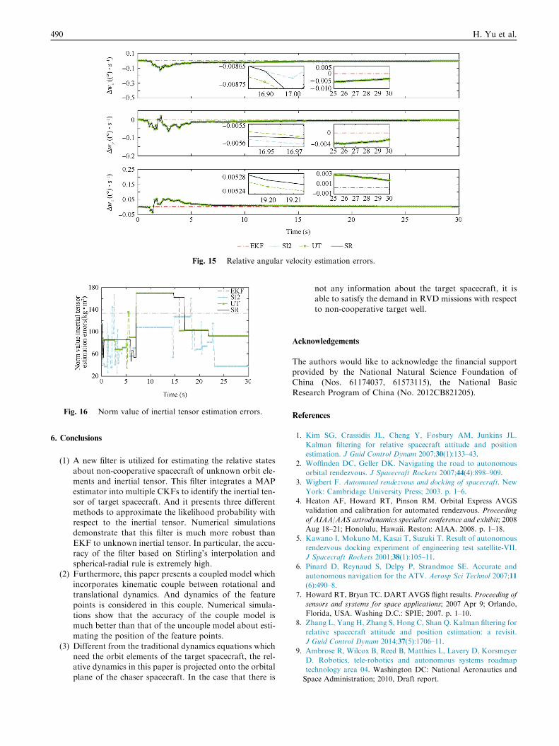
Fig. 15 Relative angular velocity estimation errors.
Fig. 16 Norm value of inertial tensor estimation errors.
490 H. Yu et al.
6. Conclusions
(1) A new filter is utilized for estimating the relative statesabout non-cooperative spacecraft of unknown orbit ele-
ments and inertial tensor. This filter integrates a MAPestimator into multiple CKFs to identify the inertial ten-sor of target spacecraft. And it presents three different
methods to approximate the likelihood probability withrespect to the inertial tensor. Numerical simulationsdemonstrate that this filter is much more robust than
EKF to unknown inertial tensor. In particular, the accu-racy of the filter based on Stirling’s interpolation andspherical-radial rule is extremely high.
(2) Furthermore, this paper presents a coupled model which
incorporates kinematic couple between rotational andtranslational dynamics. And dynamics of the featurepoints is considered in this couple. Numerical simula-
tions show that the accuracy of the couple model ismuch better than that of the uncouple model about esti-mating the position of the feature points.
(3) Different from the traditional dynamics equations whichneed the orbit elements of the target spacecraft, the rel-ative dynamics in this paper is projected onto the orbital
plane of the chaser spacecraft. In the case that there is
not any information about the target spacecraft, it isable to satisfy the demand in RVD missions with respectto non-cooperative target well.
Acknowledgements
The authors would like to acknowledge the financial supportprovided by the National Natural Science Foundation ofChina (Nos. 61174037, 61573115), the National Basic
Research Program of China (No. 2012CB821205).
References
1. Kim SG, Crassidis JL, Cheng Y, Fosbury AM, Junkins JL.
Kalman filtering for relative spacecraft attitude and position
estimation. J Guid Control Dynam 2007;30(1):133–43.
2. Woffinden DC, Geller DK. Navigating the road to autonomous
orbital rendezvous. J Spacecraft Rockets 2007;44(4):898–909.
3. Wigbert F. Automated rendezvous and docking of spacecraft. New
York: Cambridage University Press; 2003. p. 1–6.
4. Heaton AF, Howard RT, Pinson RM. Orbital Express AVGS
validation and calibration for automated rendezvous. Proceeding
of AIAA/AAS astrodynamics specialist conference and exhibit; 2008
Aug 18–21; Honolulu, Hawaii. Reston: AIAA. 2008. p. 1–18.
5. Kawano I, Mokuno M, Kasai T, Suzuki T. Result of autonomous
rendezvous docking experiment of engineering test satellite-VII.
J Spacecraft Rockets 2001;38(1):105–11.
6. Pinard D, Reynaud S, Delpy P, Strandmoe SE. Accurate and
autonomous navigation for the ATV. Aerosp Sci Technol 2007;11
(6):490–8.
7. Howard RT, Bryan TC. DART AVGS flight results. Proceeding of
sensors and systems for space applications; 2007 Apr 9; Orlando,
Florida, USA. Washing D.C.: SPIE; 2007. p. 1–10.
8. Zhang L, Yang H, Zhang S, Hong C, Shan Q. Kalman filtering for
relative spacecraft attitude and position estimation: a revisit.
J Guid Control Dynam 2014;37(5):1706–11.
9. Ambrose R, Wilcox B, Reed B, Matthies L, Lavery D, Korsmeyer
D. Robotics, tele-robotics and autonomous systems roadmap
technology area 04. Washington DC: National Aeronautics and
Space Administration; 2010, Draft report.

Relative dynamics estimation of non-cooperative spacecraft with unknown orbit elements and inertial tensor 491
10. Lanzerotti LJ. Assessment of options for extending the life of the
hubble space telescope. Washington D.C.: National Academies
Press; 2005, Final report.
11. Fasano G, Grassi M, Accardo D. A stereo-vision based system for
autonomous navigation of an in-orbit servicing platform. Pro-
ceeding of AIAA infotech at aerospace conference; 2009 Apr 6–9;
Seattle, Washington D.C.,USA. Reston: AIAA; 2009. p. 1–10.
12. Xu W, Liang B, Li C, Xu Y. Autonomous rendezvous and robotic
capturing of non-cooperative target in space. Robotica 2010;28
(5):705–18.
13. Liu H, Wang Z, Wang B, Li Z. Pose determination of non-
cooperative spacecraft based on multi-feature information fusion.
Proceeding of IEEE International Conference on Robotics and
Biomimetics; 2013 Dec 12–14; Shenzhen, China. Piscataway, NJ:
IEEE Press; 2013. p. 1538–43.
14. Kelsey JM, Byrne J, Cosgrove M, Seereeram S, Mehra RK.
Vision-based relative pose estimation for autonomous rendezvous
and docking. Proceeding of IEEE Aerospace Conference; Big Sky,
MT. Piscataway, NJ: IEEE Prsss; 2006. p. 1–20.
15. Zhou J, Bai B, Yu X. A new method of relative position and
attitude determination for non-cooperative target. J Astronaut
2011;32(3):516–21 Chinese.
16. Segal S, Gurfil P. Effect of kinematic rotation-translation coupling
on relative spacecraft translational dynamics. J Guid Control
Dynam 2009;32(3):1045–50.
17. Aghili F, Parsa K. Motion and parameter estimation of space
objects using laser-vision data. J Guid Control Dynam 2009;32
(2):537–49.
18. Zhang L, Zhang S, Yang H, Hong C, Shan Q. Relative attitude
and position estimation for a tumbling spacecraft. Aerosp Sci
Technol 2015;42:97–105.
19. Segal S, Carmi A, Gurfil P. Stereovision-based estimation of
relative dynamics between noncooperative satellites: theory and
experiments. IEEE Trans Control Syst Technol 2014;22(2):568–84.
20. Arasaratnam I, Haykin S. Cubature Kalman filters. IEEE Trans
Autom Control 2009;54(6):1254–69.
21. Christopher DK, Hanspeter S. Nonsingular attitude filtering using
modifiedRodrigues parameters. J Astronaut Sci 2010;57(4):777–91.
22. Bay H, Ess A, Tuytelaars T, van Gool L. Speeded-up robust
features (SURF). Comput Vis Image Underst 2008;110(3):346–59.
23. Crassidis JL, Junkins JL. Optimal estimation of dynamic sys-
tems. Boca Raton: Chapman & Hall/CRC; 2004. p. 270–82.
24. Yu H, Song S, Wang S. Interaction cubature Kalman filter and its
application. Control and Decision 2015;30 (9):1660–6 (Chinese).
25. Nrgaard M, Poulsen NK, Ravn O. New developments in
state estimation for nonlinear systems. Automatica 2000;36(11):
1627–38.
26. Julier SJ, Uhlmann JK. Unscented filtering and nonlinear estima-
tion. Proc IEEE 2004;92(3):401–22.
Yu Han received his Ph.D. degree in control science and engineering
from Harbin Institute of Technology in 2015. Currently, he is an
engineer at Beijing Institute of Astronautical Systems Engineering. His
main research interests include vision-aided inertial navigation, non-
linear filter and effectiveness evaluation.
Zhang Xiujie received her M.S. degree in intelligence engineering from
Chiba University, Chiba, Japan, in 2006. She received the Ph.D. degree
in control theory and application from Harbin Institute of Technol-
ogy, Harbin, China, in 2013. Her current research interests include
evolutionary computation, nonlinear filter and their applications.
Liu Lingyu received his Ph.D. degree in navigation guidance and
control from Beihang University in 2012. Currently, he is an engineer
at Beijing Institute of Astronautical Systems Engineering. His main
research interests include simulation technology and flight simulation.
Wang Shuo received his M.S. degree in control science and engineering
from Heilongjiang University in 2011. Currently, he is a Ph.D. student
at Harbin Institute of Technology. His main research interests include
vision navigation, nonlinear filter and data fusion.
Song Shenmin received his Ph.D. degree in control theory and appli-
cation from Harbin Institute of Technology in 1996. He carried out
postdoctoral research at Tokyo University from 2000 to 2002. He is
currently a professor at the School of Astronautics, Harbin Institute of
Technology. His main research interests include spacecraft guidance
and control, intelligent control, and nonlinear theory and application.