electromagnetic driven selfpiercing riveting of metal ... · electromagnetic driven selfpiercing...
TRANSCRIPT
Electromagnetic driven selfpiercing riveting
of metal & composite sheets
Charlotte Beerwald
Poynting GmbH, Dortmund, Germany
Final Seminar, 24th February 2016, BWI, Ghent, Belgium

Final Seminar, 24th February 2016
Belgium Welding Institute, Ghent
Company Profile
Since 13 years POYNTING company is equipment manufacturer for diverse applications of
Pulsed Power Technologies
We bring new technologies into industrial application and
support research centres with specific equipment developments
Fields of activity and products:
High Voltage Power Supplies
average power from 3kW to several 100 kW,
output voltage from 1kV to 100kV,
repetition rates from 1Hz to several kHz
Pulse Generators
modules as well as turn-key systems
optimised for the application (adjusted to the “load”)
Engineering Services and Simulation
Pulse Modulator for ESS, Lund
with integrated
High Voltage Power Supply
225 kW, 6 kV

Final Seminar, 24th February 2016
Belgium Welding Institute, Ghent
Characteristics of EMF Pulse Generators
Selected pulse generators with different specifications
Poynting / model type SMU1500 / SMU2000
ultra small design
Maximum charging energy
(at charging voltage)
1.5 kJ / 2 kJ
(6.2kV / 8kV)
Short circuit frequency
(shorted without coil) 65 kHz
Maximum permitted
discharge current 60-100 kA
SSG-3020
diff. working chambers
30 kJ
(20 kV)
100 kHz
800 kA
SMU COMPACT __TH
thyristor switched ex.
9kJ to 48 kJ
(< 8 kV)
> 30 kHz
up to 50 kHz
up to 1.280 kA
9 kJ x no. of modules
(15 kV)
>50 kHz
150 kA x no. of modules
SMU MODULAR 0915
(properties per module)
SMU MODULAR series:
Modules (optional 6kJ or 9kJ each) of any number
can be connected in serial control chain collecting
the power by parallel connection of the HV output
SMU COMPACT series:
Compact machine design, which has to be
configured in optimum accordance to the
forming task

Final Seminar, 24th February 2016
Belgium Welding Institute, Ghent
Electromagnetic Forming Process
Compression Coil
Workpiece (tubular)
Capacitor Bank
High Current Switch
CompressionExpansion
Flat Forming
Electromagnetic Forming (EMF) is a High Velocity Forming Process using the energy density of a pulsed
magnetic field to form or to accelerate workpieces of good electrical conductivity.
Process Typesresulting of the coil-workpiece arrangement
C
Li
Ri
EMF is used for joining, forming, and cutting of thin-walled tubes
and sheets, but joining by compression of tubular parts is actually
the most important application in series production.
Final Seminar, 24th February 2016
Belgium Welding Institute, Ghent
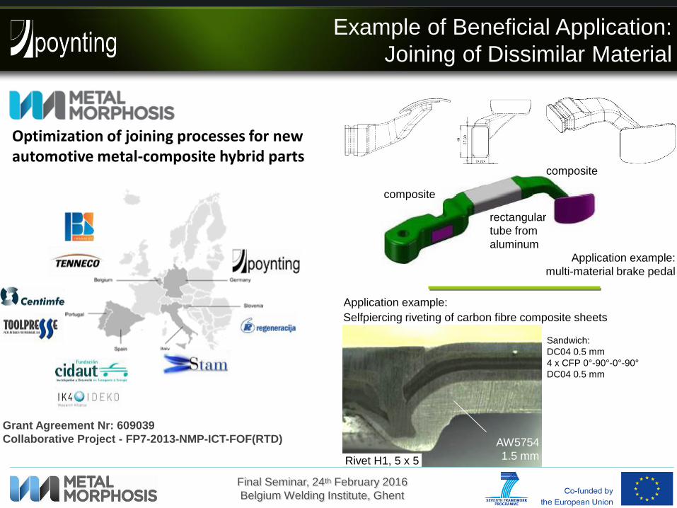
Example of Beneficial Application:
Joining of Dissimilar Material
Grant Agreement Nr: 609039
Collaborative Project - FP7-2013-NMP-ICT-FOF(RTD)
Optimization of joining processes for new automotive metal-composite hybrid parts
composite
composite
rectangular
tube from
aluminum
Selfpiercing riveting of carbon fibre composite sheets
Rivet H1, 5 x 5
AW5754
1.5 mm
Sandwich:
DC04 0.5 mm
4 x CFP 0°-90°-0°-90°
DC04 0.5 mm
Application example:
Application example:
multi-material brake pedal
Final Seminar, 24th February 2016
Belgium Welding Institute, Ghent
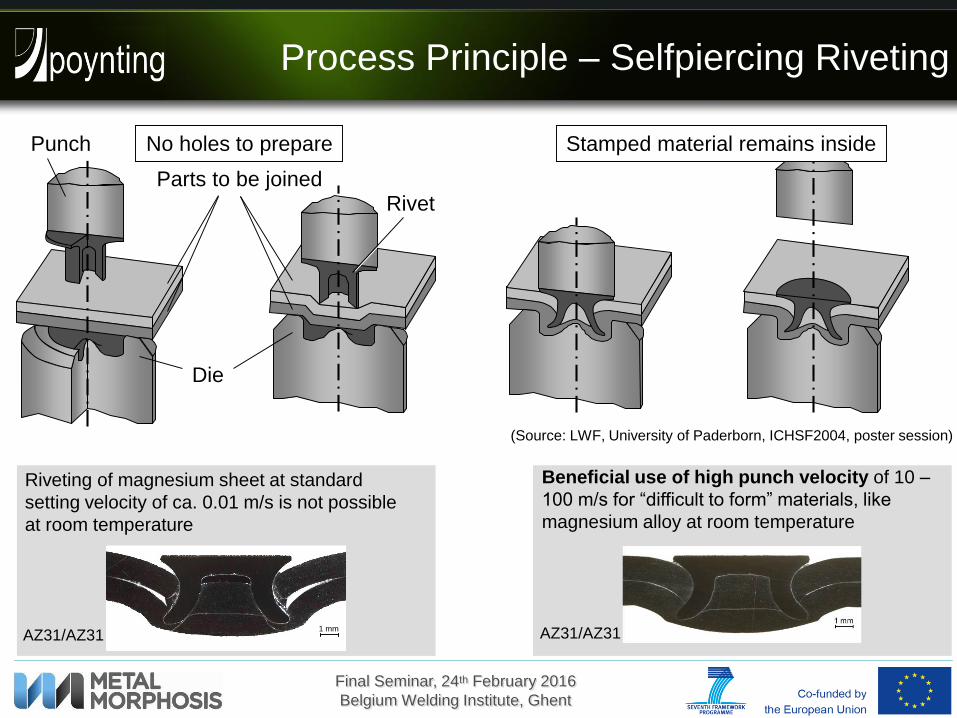
Process Principle – Selfpiercing Riveting
Rivet
Punch
Parts to be joined
Die
Riveting of magnesium sheet at standard
setting velocity of ca. 0.01 m/s is not possible
at room temperature
1 mm1 mmAZ31/AZ31
Beneficial use of high punch velocity of 10 –
100 m/s for “difficult to form” materials, like
magnesium alloy at room temperature
(Source: LWF, University of Paderborn, ICHSF2004, poster session)
AZ31/AZ31
No holes to prepare Stamped material remains inside

Final Seminar, 24th February 2016
Belgium Welding Institute, Ghent
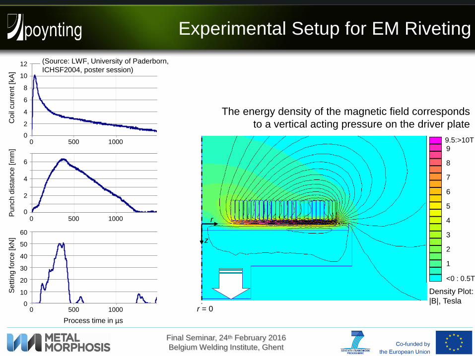
Experimental Setup for EM Riveting
Coil
winding
Mass
Flat coil I
Flat coil II
(optional)
Driver
plate
Punch
Sheets to
be joined
Rivet
DieSheets to
be joined
Punch
Flat coil
Driver
plate

Final Seminar, 24th February 2016
Belgium Welding Institute, Ghent
Experimental Setup for EM Riveting
Coil
winding
Mass
Flat coil I
Flat coil II
(optional)
Driver
plate
Punch
Sheets to
be joined
C
Li Ri
The energy density of the magnetic field corresponds
to a vertical acting pressure on the driver plate
r = 0
r
z
9.5:>10T
8
5
1
<0 : 0.5T
Density Plot:
|B|, Tesla
2
3
4
6
7
9
Final Seminar, 24th February 2016
Belgium Welding Institute, Ghent
Experimental Setup for EM Riveting
The energy density of the magnetic field corresponds
to a vertical acting pressure on the driver plate
0
10
20
30
40
50
60
0 500 1000 1500 2000
Zeit [ms]
Kra
ft [k
N]
Process time in µs
0 500 1000
Sett
ing
forc
e [kN
]
0
10
20
30
40
50
60
0
2
4
6
8
10
12
0 500 1000 1500 2000
Zeit [ms]
Str
om [k
A]
0 500 1000
Coil
curr
ent [k
A]
0
2
4
6
8
10
12
0
1
2
3
4
5
6
7
0 500 1000 1500 2000
Zeit [ms]
Stem
pelw
eg [m
m]
0 500 1000
Pu
nch
dis
tan
ce
[m
m]
0
2
4
6
r = 0
r
z
9.5:>10T
8
5
1
<0 : 0.5T
Density Plot:
|B|, Tesla
2
3
4
6
7
9
(Source: LWF, University of Paderborn,
ICHSF2004, poster session)

Final Seminar, 24th February 2016
Belgium Welding Institute, Ghent
Parameter Variation – Pulse Shape
flat coil: F85-20/30
upper sheet: AC150, 1.2mm
lower sheet: AW5754, 1.5mm
rivet: Rivset® H1 5x5 (d x l)
energy: 650 J (SMU modular)
Variation of pulse shape and discharge energy efficiency
discharge circuit properties can be changed either by capacitance of energy storage or by change of coil inductance
required pulse shape shall correspond to the weight of the punch
F85-06/12
F85-16/30
F85-20/30
weight of punch: ~ 310 g

Final Seminar, 24th February 2016
Belgium Welding Institute, Ghent
Parameter Variation – Rivet and Die
C-FRK n x h
Ø k
Ø n
h
C-SKR n x h
Ø k
Ø n
h
LWF-1 Boellhoff - C Boellhoff - B Boellhoff - A
Aluminium Alloy thickness
AW 5754 H22 1.5 mm 2.0 mm
AC 150 T4 1.2 mm
AW 6082 T6 1.5 mm 2.0 mm
Joining Task: Riveting of CFRP Sheet to Aluminium Sheet
CFRP Samples (Ideko): thickness 1.5 mm – 1.7 mmthree biaxial carbon fabrics
Rivets from different types:head diameter
Ø k: 7.8 mmshaft diameter
Ø n: 5.3 mm
different shaft length different hardness (H0,
H1, H2)
Riveting Dies:
Rivets and dies have been provided by
RIVSET®

Final Seminar, 24th February 2016
Belgium Welding Institute, Ghent
Quality Evaluation by Shear Test
Fz
Fz
60
46
10
5
23
0
13
8
Fz
Fz
Dimensions for thickness 1.5 < t ≤ 3
Sample geometry and test configuration according to EN ISO 14273 (spot welding)
Fz
Fz
Final Seminar, 24th February 2016
Belgium Welding Institute, Ghent
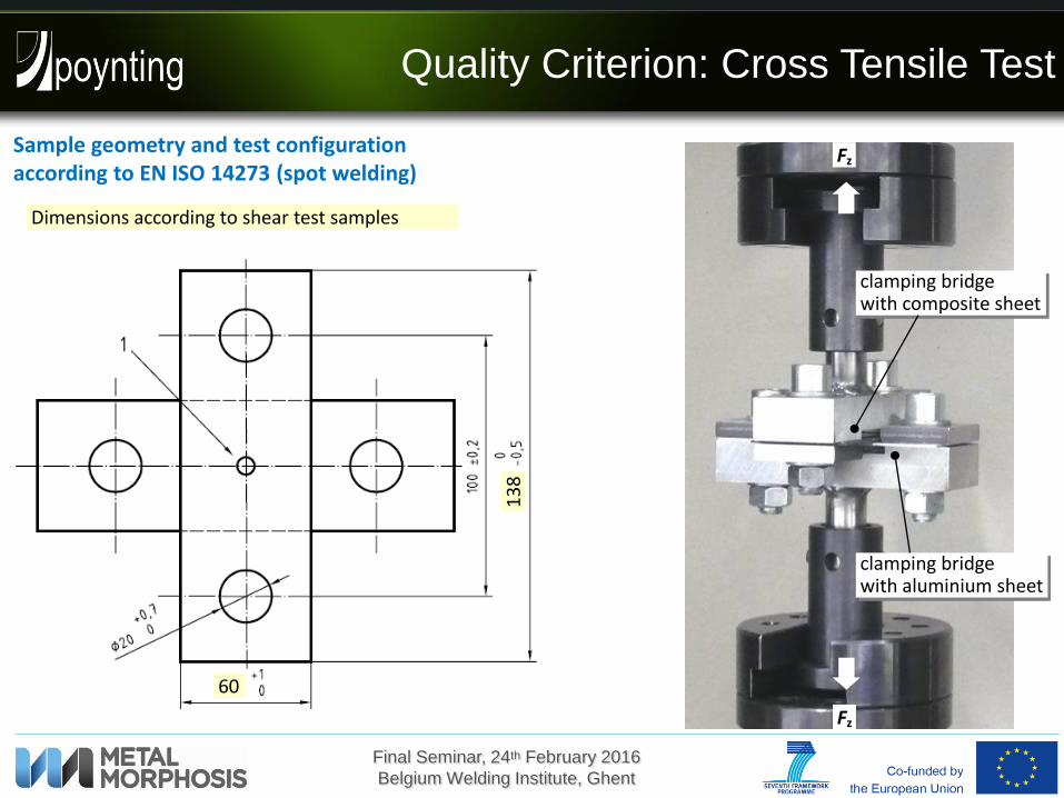
Quality Criterion: Cross Tensile Test
Dimensions according to shear test samples
60
13
8
Fz
Fz
clamping bridge with aluminium sheet
clamping bridge with composite sheet
Sample geometry and test configuration according to EN ISO 14273 (spot welding)

Final Seminar, 24th February 2016
Belgium Welding Institute, Ghent
Visual Check of Rivet Setting Quality
EMR043
Rivet: RIVSET® SKR 5 x 5 H2
Die side sheet: AW5754; 2.0 mm
Punch side sheet: CFRP (Ideko) 1,7 mm
Pulse Energy: 580 J
Cover sheet: -- none --
Die: LWF-1
EMR053
Rivet: RIVSET® FRK 5 x 5 H0
Die side sheet: AW5754; 1.5 mm
Punch side sheet: CFRP (Ideko) 1,6 mm
Pulse Energy: 500 J
Cover sheet: -- none --
Die: LWF-1
EMR059
Rivet: RIVSET® SKR 5 x 5 H2
Die side sheet: AW5754; 2.0 mm
Punch side sheet: CFRP (Ideko) 1,6 mm
Pulse Energy: 550 J
Cover sheet: -- none --
Die: LWF-1

Final Seminar, 24th February 2016
Belgium Welding Institute, Ghent
Quality Tests on Flat Head Rivets
Rivet stucks in punch-sided sheet, ripped out of the die-sided sheet
Tensile tests with rivet type FKR show better results than the direct SRK rivet
Shear test
rivet SRK 5x5 H2 (580J)
rivet FKR 5x5 H0
CFRP 0/90, emr082 (550J) CFRP ±45, emr081 (550J)
CFRP 1.6mm – AW5754 2.0mm, Die „LWF-1“
rivet SRK 5x5 H2 (580J, emr044)
rivet FKR 5x5 H0, different fibre orientation
CFRP 0/90, emr075 (550J)
CFRP ±45, emr070 (550J)
change of die shape „C“:
CFRP 0/90, emr100 (650J)
CFRP ±45, emr095 (650J)
Final Seminar, 24th February 2016
Belgium Welding Institute, Ghent
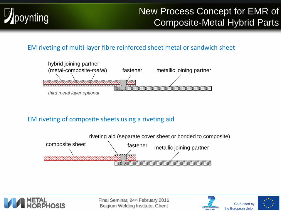
New Process Concept for EMR of
Composite-Metal Hybrid Parts
EM riveting of multi-layer fibre reinforced sheet metal or sandwich sheet
EM riveting of composite sheets using a riveting aid
metallic joining partner
hybrid joining partner
(metal-composite-metal)
third metal layer optional
fastener
riveting aid (separate cover sheet or bonded to composite)
metallic joining partnercomposite sheet fastener
Final Seminar, 24th February 2016
Belgium Welding Institute, Ghent
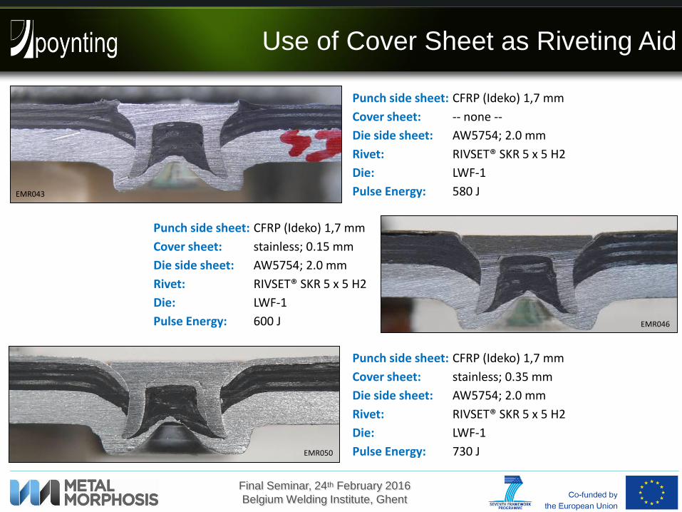
Use of Cover Sheet as Riveting Aid
EMR043
EMR046
Rivet: RIVSET® SKR 5 x 5 H2
Die side sheet: AW5754; 2.0 mm
Punch side sheet: CFRP (Ideko) 1,7 mm
Pulse Energy: 600 J
Cover sheet: stainless; 0.15 mm
Die: LWF-1
EMR050
Rivet: RIVSET® SKR 5 x 5 H2
Die side sheet: AW5754; 2.0 mm
Punch side sheet: CFRP (Ideko) 1,7 mm
Pulse Energy: 580 J
Cover sheet: -- none --
Die: LWF-1
Rivet: RIVSET® SKR 5 x 5 H2
Die side sheet: AW5754; 2.0 mm
Punch side sheet: CFRP (Ideko) 1,7 mm
Pulse Energy: 730 J
Cover sheet: stainless; 0.35 mm
Die: LWF-1

Final Seminar, 24th February 2016
Belgium Welding Institute, Ghent
Evaluation by Shear Test Results
EMR078
Rivet stucks in die-sided sheet,but rivet “head” punched the composite
Type of failure 1:
Force at first failure:
2130 N
2516 N
2720 N
Influence of cover sheet
Final Seminar, 24th February 2016
Belgium Welding Institute, Ghent
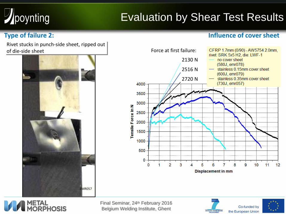
Evaluation by Shear Test Results
Type of failure 2:
Force at first failure:
2130 N
2516 N
2720 N
EMR057
Rivet stucks in punch-side sheet, ripped out of die-side sheet
Influence of cover sheet

Final Seminar, 24th February 2016
Belgium Welding Institute, Ghent
Evaluation by Shear Test Results
Type of failure 1: Influence of cover sheetRivet stucks in die-side sheet, composite failed along complete drawing length
EMR080
die-side sheet: AW6082 T6, 2.0 mmCover sheet: stainless, 0.35 mm

Final Seminar, 24th February 2016
Belgium Welding Institute, Ghent
Improvement by Higher Strength of
Die Side Sheet (Aluminium Alloy)
CFRP 1.6mm – AW5754 2.0mm, rivet SRK 5x5 H2
no cover sheet (580J, emr044)
stainless 0.15mm cover sheet (600J, emr047)
stainless 0.35mm cover sheet (730J, emr051)
CFRP 1.6mm – AW6082 2.0mm, rivet SRK 5x5 H2
stainless 0.35mm cover sheet (750J, emr069)
Rivet stucks in punch-sided sheet, ripped out of the die-sided sheet
The higher strength of die side sheet caused higher cross tension strength
BUT
Principle correlation between shear strength and cross tension strength

Final Seminar, 24th February 2016
Belgium Welding Institute, Ghent
Improvement by Shape of Die
& Rivet Length
EMR115
Rivet: RIVSET® SKR 5 x 6 H2
Die side sheet: AW5754; 2.0 mm
Punch side sheet: CFRP (Ideko) 1,8 mm
Pulse Energy: 950 J
Cover sheet: stainless; 0.35 mm
Die: „C“ (sphere)
EMR050
Rivet: RIVSET® SKR 5 x 5 H2
Die side sheet: AW5754; 2.0 mm
Punch side sheet: CFRP (Ideko) 1,7 mm
Pulse Energy: 730 J
Cover sheet: stainless; 0.35 mm
Die: LWF-1
Final Seminar, 24th February 2016
Belgium Welding Institute, Ghent
Improvement by Shape of Die
& Rivet Length
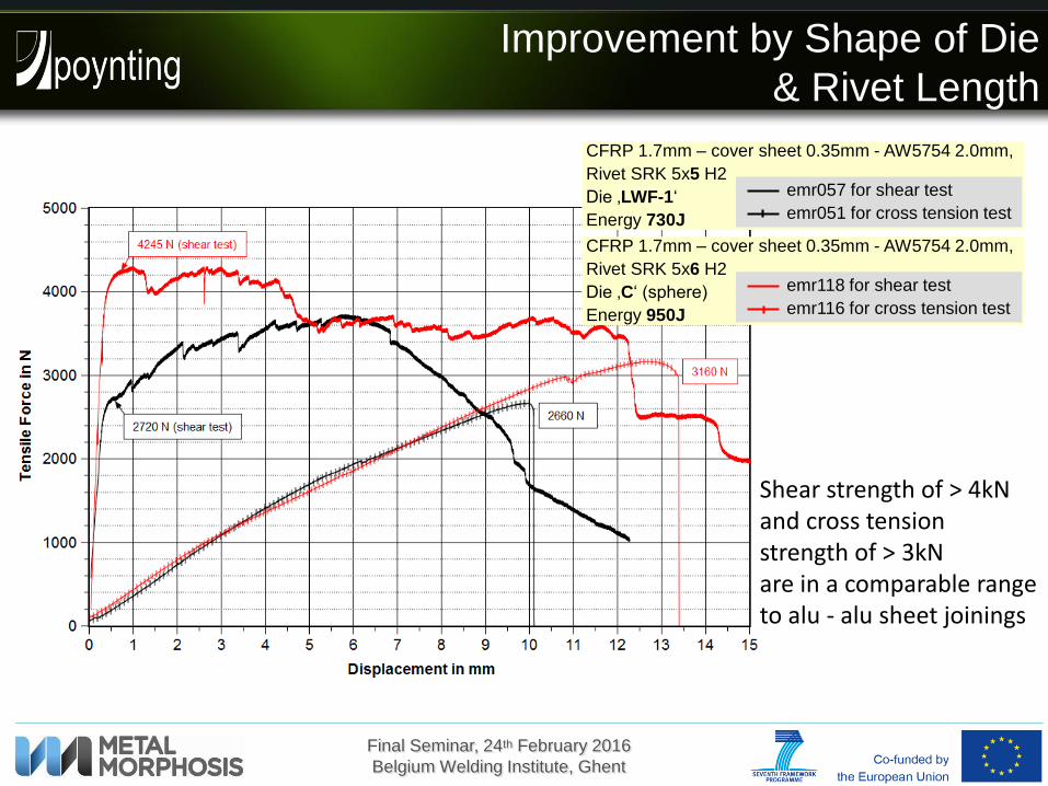
CFRP 1.7mm – cover sheet 0.35mm - AW5754 2.0mm,
Rivet SRK 5x5 H2
Die ‚LWF-1‘
Energy 730J
emr057 for shear test
emr051 for cross tension test
CFRP 1.7mm – cover sheet 0.35mm - AW5754 2.0mm,
Rivet SRK 5x6 H2
Die ‚C‘ (sphere)
Energy 950J
emr118 for shear test
emr116 for cross tension test
Shear strength of > 4kN and cross tension strength of > 3kN are in a comparable range to alu - alu sheet joinings
Final Seminar, 24th February 2016
Belgium Welding Institute, Ghent
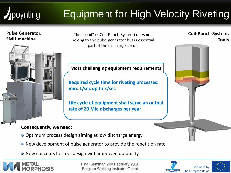
Equipment for High Velocity Riveting
Pulse Generator,SMU machine
The “Load” (= Coil-Punch-System) does not belong to the pulse generator but is essential
part of the discharge circuit
Coil-Punch-System, Tools
Required cycle time for riveting processes:min. 1/sec up to 3/sec
Life cycle of equipment shall serve an output rate of 20 Mio discharges per year
Most challenging equipment requirements
Optimum process design aiming at low discharge energy
New development of pulse generator to provide the repetition rate
New concepts for tool design with improved durability
Consequently, we need:
Final Seminar, 24th February 2016
Belgium Welding Institute, Ghent
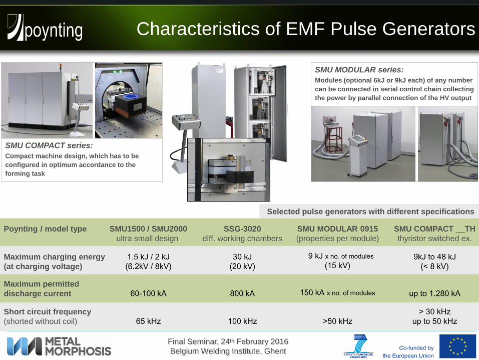
Characteristics of EMF Pulse Generators
Selected pulse generators with different specifications
Poynting / model type SMU1500 / SMU2000
ultra small design
Maximum charging energy
(at charging voltage)
1.5 kJ / 2 kJ
(6.2kV / 8kV)
Short circuit frequency
(shorted without coil) 65 kHz
Maximum permitted
discharge current 60-100 kA
SSG-3020
diff. working chambers
30 kJ
(20 kV)
100 kHz
800 kA
SMU COMPACT __TH
thyristor switched ex.
9kJ to 48 kJ
(< 8 kV)
> 30 kHz
up to 50 kHz
up to 1.280 kA
9 kJ x no. of modules
(15 kV)
>50 kHz
150 kA x no. of modules
SMU MODULAR 0915
(properties per module)
SMU MODULAR series:
Modules (optional 6kJ or 9kJ each) of any number
can be connected in serial control chain collecting
the power by parallel connection of the HV output
SMU COMPACT series:
Compact machine design, which has to be
configured in optimum accordance to the
forming task
Final Seminar, 24th February 2016
Belgium Welding Institute, Ghent
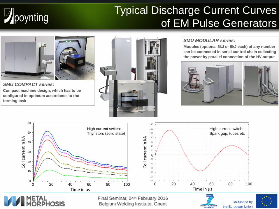
Typical Discharge Current Curves
of EM Pulse Generators
SMU MODULAR series:
Modules (optional 6kJ or 9kJ each) of any number
can be connected in serial control chain collecting
the power by parallel connection of the HV output
SMU COMPACT series:
Compact machine design, which has to be
configured in optimum accordance to the
forming task
Co
il cu
rren
t in
kA
Time in µs0 20 40 60 80 100
Time in µs
Co
il cu
rren
t in
kA
Time in µs0 20 40 60 80 100
0
High current switch:
Thyristors (solid state)
High current switch:
Spark gap, tubes etc

Final Seminar, 24th February 2016
Belgium Welding Institute, Ghent
New Design of High Repetition Pulse Generator:
SMU COMPACT 0208 TH – HR60
Pulse Energizing andEnergy Recovery
1 sec (cycle time)
High repetition rate of 1 Hz by new circuit design with energy recovery
Riveting process
CL
≈ 31% energy recovery

Final Seminar, 24th February 2016
Belgium Welding Institute, Ghent
New Design of EMR Pulse Generator:
SMU COMPACT 0208 TH – HR60
1 sec (cycle time)
High repetition rate of 1 Hz by new circuit design with energy recovery
Riveting process
Capacitor bank and tool system
Cooled test coil
• excellent pulse to pulse accuracy
• 8h durability testing @ 1Hzsuccessful component test
• water-cooled test coil, nevertheless recognized temperature problem at the load
High repetition pulse generatorMax. energy: 1.8 kJ @ 7.75 kV
High current switches: ThyristorsLong life pulse capacitors
Final Seminar, 24th February 2016
Belgium Welding Institute, Ghent
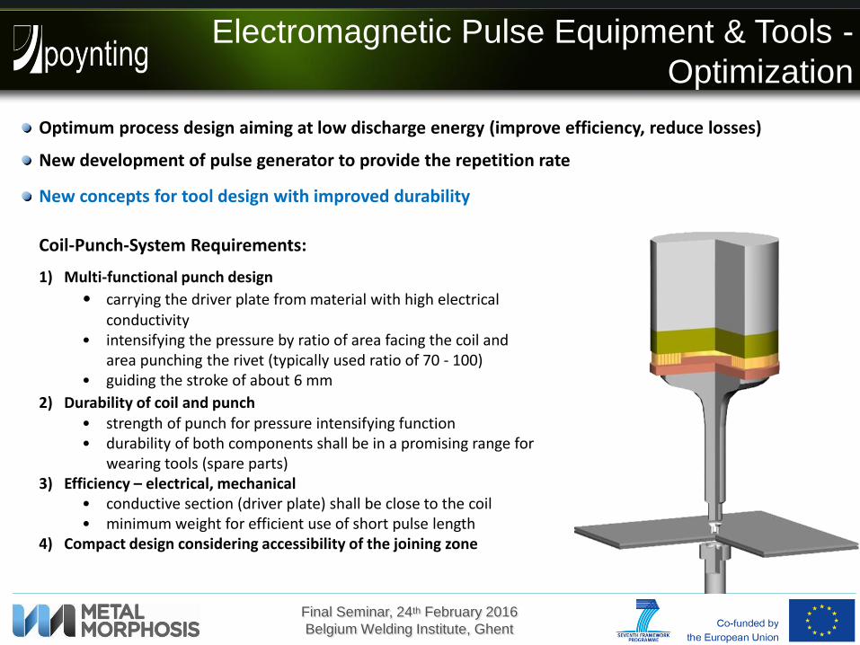
1) Multi-functional punch design
• carrying the driver plate from material with high electrical conductivity
• intensifying the pressure by ratio of area facing the coil and area punching the rivet (typically used ratio of 70 - 100)
• guiding the stroke of about 6 mm
2) Durability of coil and punch• strength of punch for pressure intensifying function• durability of both components shall be in a promising range for
wearing tools (spare parts)3) Efficiency – electrical, mechanical
• conductive section (driver plate) shall be close to the coil • minimum weight for efficient use of short pulse length
4) Compact design considering accessibility of the joining zone
Electromagnetic Pulse Equipment & Tools -
Optimization
Optimum process design aiming at low discharge energy (improve efficiency, reduce losses)
New development of pulse generator to provide the repetition rate
New concepts for tool design with improved durability
Coil-Punch-System Requirements:

Final Seminar, 24th February 2016
Belgium Welding Institute, Ghent
performed at DMRC,Paderborn, Germany
Punch 1,light version:298 g small diameter Ø 8
high pressure area(rivet side)
Manually optimised design (target weight: 150 g)
high strength steel shaftand disc
aluminium driver plate
large diameter Ø 88low pressure area (coil side) aluminium
driver plate
high strength steel shaft
titanium structure
r
z
Topology optimization for SLM manufacturing
Optimization of Punch for EMR
result of third optimization loop
Final Seminar, 24th February 2016
Belgium Welding Institute, Ghent
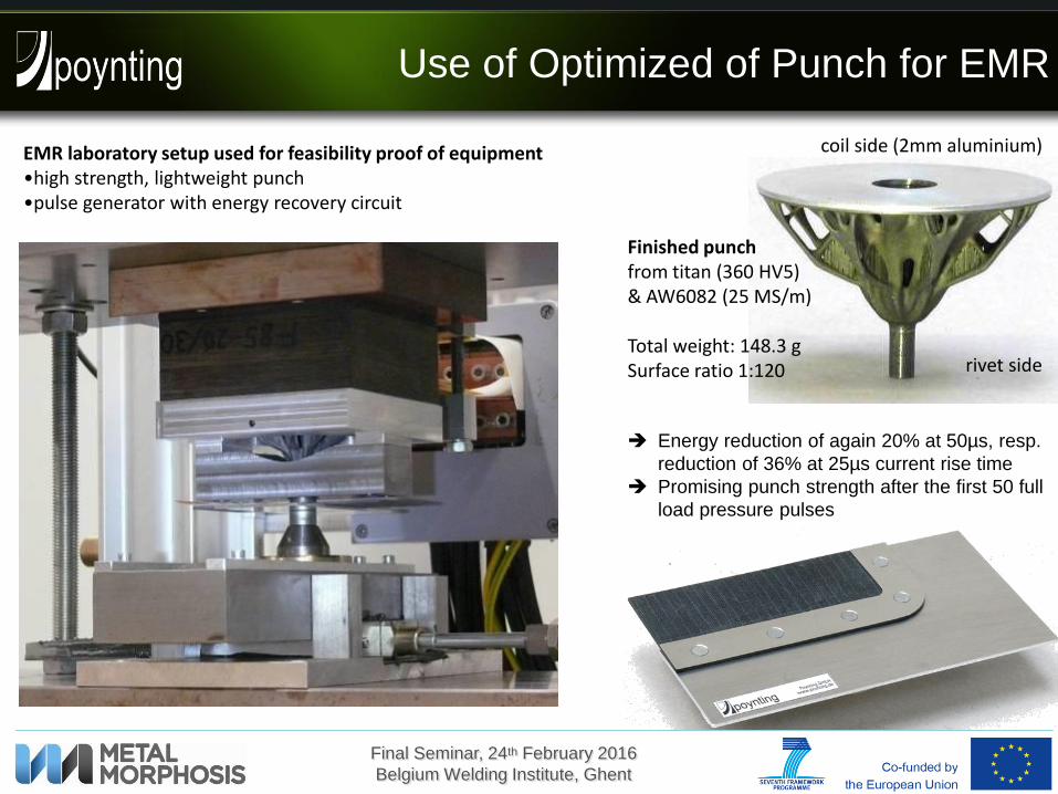
Use of Optimized of Punch for EMR
EMR laboratory setup used for feasibility proof of equipment•high strength, lightweight punch•pulse generator with energy recovery circuit
Energy reduction of again 20% at 50µs, resp.
reduction of 36% at 25µs current rise time
Promising punch strength after the first 50 full
load pressure pulses
Finished punchfrom titan (360 HV5)& AW6082 (25 MS/m)
Total weight: 148.3 gSurface ratio 1:120
coil side (2mm aluminium)
rivet side
Final Seminar, 24th February 2016
Belgium Welding Institute, Ghent
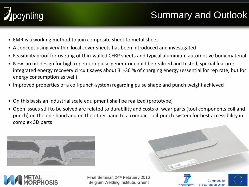
Summary and Outlook
• EMR is a working method to join composite sheet to metal sheet
• A concept using very thin local cover sheets has been introduced and investigated
• Feasibility proof for riveting of thin-walled CFRP sheets and typical aluminium automotive body material
• New circuit design for high repetition pulse generator could be realized and tested, special feature: integrated energy recovery circuit saves about 31-36 % of charging energy (essential for rep rate, but for energy consumption as well)
• Improved properties of a coil-punch-system regarding pulse shape and punch weight achieved
• On this basis an industrial scale equipment shall be realized (prototype)
• Open issues still to be solved are related to durability and costs of wear parts (tool components coil and punch) on the one hand and on the other hand to a compact coil-punch-system for best accessibility in complex 3D parts