reducing radon levels in homes - a canadian guide for
TRANSCRIPT

Reducing Radon Levels in Existing Homes: A Canadian Guide for Professional Contractors

Health Canada is the federal department responsible for helping the people of Canada maintain and improve their health. We assess the safety of drugs and many consumer products, help improve the safety of food, and provide information to Canadians to help them make healthy decisions. We provide health services to First Nations people and to Inuit communities. We work with the provinces to ensure our health care system serves the needs of Canadians.
Published by authority of the Minister of Health.
Reducing Radon Levels in Existing Homes: A Canadian Guide for Professional Contractorsis available on Internet at the following address: www.hc-sc.gc.ca/ewh-semt/pubs/radiation/radon_contractors-entrepreneurs/index-eng.php
Également disponible en français sous le titre : Réduire les concentrations de radon dans les maisons existantes : guide canadien à l’usage des entrepreneurs professionnels
This publication can be made available on request in a variety of alternative formats.
For further information or to obtain additional copies, please contact: Publications Health Canada Ottawa, Ontario K1A 0K9 Tel.: 613-954-5995 Fax: 613-941-5366 E-Mail: [email protected]
© Her Majesty the Queen in Right of Canada, represented by the Minister of Health, 2010
This publication may be reproduced without permission provided the source is fully acknowledged.
Cat. : H128-1/11-653E-PDFISBN : 978-1-100-18472-2

iReducing Radon Levels in Existing Homes: A Canadian Guide for Professional Contractors
Chapter 1: An Overview of Radon
Notice
The following guide has been written to provide professional building contractors with information on radon mitigation techniques for existing houses in contact with soil. The guide is based on the best information currently available, and has been reviewed by a committee comprising stakeholders from the housing industry. This guide is not a substitute for building regulations currently in effect. It is the contractor’s responsibility to ensure that they comply with the applicable health, safety and building code standards. The author (Health Canada) is not responsible for any damage, injury, or costs as a result of using this publication.
Acknowledgements
Health Canada would like to thank Arthur Scott for development of the original document; and extends sincere gratitude to the dedicated people who assisted in the development of the guide by providing ideas, comments, and suggested changes.
Working Group Coordinator Isabelle Vézina, Health Canada
Working Group Members
• Valois Bérubé, Société d’habitation du Québec
• Henri Bouchard, Corporation des Maîtres mécaniciens en tuyauterie du Québec
• Jean-Claude Dessau, Ministère de la Santé et des Services Sociaux du Québec
• Don Fugler, Patrick Gautreau and Wendy Pollard, Canada Mortgage and Housing Corporation
• Stéphane Hallé, École de technologie supérieure
• Jean-Marc Leclerc et Patrick Poulin, Institut national de santé publique du Québec
• Marc-Olivier Boudreau, Mathieu Brossard, Marielou Verge and Jeff Whyte, Health Canada
Special thanks for their valuable comments to our international collaborators: William J. Angell and Jack Bartholomew Jr. and to the Kitigan Zibi Community for sharing their photos.

iiReducing Radon Levels in Existing Homes: A Canadian Guide for Professional Contractors
Table of ContentsChapter 1 – An Overview of Radon . . . . . . . . . . . . . . . . . . . . . . . . . . . . . . . . . . . . . . .1
1.1 What is Radon? . . . . . . . . . . . . . . . . . . . . . . . . . . . . . . . . . . . . . . . . . . . . . . . . . . . . . . . . . . . . . . . . .1
1.2 Why is it a Health Hazard? . . . . . . . . . . . . . . . . . . . . . . . . . . . . . . . . . . . . . . . . . . . . . . . . . . . . . . . .2
1.3 Radon Guideline . . . . . . . . . . . . . . . . . . . . . . . . . . . . . . . . . . . . . . . . . . . . . . . . . . . . . . . . . . . . . . . .2
Chapter 2 – Confirming the Radon Test was Carried Out Properly . . . . . . . . . . . . . . .4
2.1 Introduction . . . . . . . . . . . . . . . . . . . . . . . . . . . . . . . . . . . . . . . . . . . . . . . . . . . . . . . . . . . . . . . . . . . .4
2.2 Health Canada Testing Guidance . . . . . . . . . . . . . . . . . . . . . . . . . . . . . . . . . . . . . . . . . . . . . . . . . . .5
Long-Term Measurements . . . . . . . . . . . . . . . . . . . . . . . . . . . . . . . . . . . . . . . . . . . . . . . . . . . . . .5
Short-Term Measurements . . . . . . . . . . . . . . . . . . . . . . . . . . . . . . . . . . . . . . . . . . . . . . . . . . . . . .5
Chapter 3 – An Overview of Radon Reduction Systems . . . . . . . . . . . . . . . . . . . . . . . .7
3.1 How Does Radon Enter a Home? . . . . . . . . . . . . . . . . . . . . . . . . . . . . . . . . . . . . . . . . . . . . . . . . . .7
3.2 Principles of Reducing Radon Entry . . . . . . . . . . . . . . . . . . . . . . . . . . . . . . . . . . . . . . . . . . . . . . . .7
3.3 Selection of Mitigation Methods . . . . . . . . . . . . . . . . . . . . . . . . . . . . . . . . . . . . . . . . . . . . . . . . . . .8
3.4 Masonry Foundations . . . . . . . . . . . . . . . . . . . . . . . . . . . . . . . . . . . . . . . . . . . . . . . . . . . . . . . . . . . .8
3.5 Hollow Concrete Block Foundations . . . . . . . . . . . . . . . . . . . . . . . . . . . . . . . . . . . . . . . . . . . . . . . .9
3.6 Poured Concrete Foundations . . . . . . . . . . . . . . . . . . . . . . . . . . . . . . . . . . . . . . . . . . . . . . . . . . . .10
3.7 Slab-on-Grade Foundations . . . . . . . . . . . . . . . . . . . . . . . . . . . . . . . . . . . . . . . . . . . . . . . . . . . . .11
3.8 Seasonal Effects . . . . . . . . . . . . . . . . . . . . . . . . . . . . . . . . . . . . . . . . . . . . . . . . . . . . . . . . . . . . . . . .12
3.9 Summary of Mitigation Options . . . . . . . . . . . . . . . . . . . . . . . . . . . . . . . . . . . . . . . . . . . . . . . . . .13
Chapter 4 – Mitigation by Sub-Slab Depressurisation . . . . . . . . . . . . . . . . . . . . . . .15
4.1 Introduction . . . . . . . . . . . . . . . . . . . . . . . . . . . . . . . . . . . . . . . . . . . . . . . . . . . . . . . . . . . . . . . . . . .15
4.2 Feasibility Test . . . . . . . . . . . . . . . . . . . . . . . . . . . . . . . . . . . . . . . . . . . . . . . . . . . . . . . . . . . . . . . . .15
Feasibility Test Example . . . . . . . . . . . . . . . . . . . . . . . . . . . . . . . . . . . . . . . . . . . . . . . . . . . . . . . .18
4.3 System Design . . . . . . . . . . . . . . . . . . . . . . . . . . . . . . . . . . . . . . . . . . . . . . . . . . . . . . . . . . . . . . . . .19
General . . . . . . . . . . . . . . . . . . . . . . . . . . . . . . . . . . . . . . . . . . . . . . . . . . . . . . . . . . . . . . . . . . . . .19
Building Pressure Differences . . . . . . . . . . . . . . . . . . . . . . . . . . . . . . . . . . . . . . . . . . . . . . . . . . .19
Fan Flow Estimate . . . . . . . . . . . . . . . . . . . . . . . . . . . . . . . . . . . . . . . . . . . . . . . . . . . . . . . . . . . .20

iiiReducing Radon Levels in Existing Homes: A Canadian Guide for Professional Contractors
Estimate of System Pressure Drops . . . . . . . . . . . . . . . . . . . . . . . . . . . . . . . . . . . . . . . . . . . . . .24
Summary . . . . . . . . . . . . . . . . . . . . . . . . . . . . . . . . . . . . . . . . . . . . . . . . . . . . . . . . . . . . . . . . . . . .25
Fan Selection . . . . . . . . . . . . . . . . . . . . . . . . . . . . . . . . . . . . . . . . . . . . . . . . . . . . . . . . . . . . . . . .25
Measurements in other seasons . . . . . . . . . . . . . . . . . . . . . . . . . . . . . . . . . . . . . . . . . . . . . . . . .26
Sub-slab system installation examples . . . . . . . . . . . . . . . . . . . . . . . . . . . . . . . . . . . . . . . . . . . .28
Chapter 5 – Mitigation of Exposed Soil . . . . . . . . . . . . . . . . . . . . . . . . . . . . . . . . . . .29
5.1 Introduction . . . . . . . . . . . . . . . . . . . . . . . . . . . . . . . . . . . . . . . . . . . . . . . . . . . . . . . . . . . . . . . . . . .29
5.2 Sub-membrane Depressurisation . . . . . . . . . . . . . . . . . . . . . . . . . . . . . . . . . . . . . . . . . . . . . . . . .29
5.3 Sizing the System Fan for Sub-membrane Depressurization . . . . . . . . . . . . . . . . . . . . . . . . . . .31
Chapter 6 – Mitigation by Sump and Drainage System Depressurization . . . . . . . . . 32
6.1 Introduction . . . . . . . . . . . . . . . . . . . . . . . . . . . . . . . . . . . . . . . . . . . . . . . . . . . . . . . . . . . . . . . . . . .32
6.2 Closing a Sump System . . . . . . . . . . . . . . . . . . . . . . . . . . . . . . . . . . . . . . . . . . . . . . . . . . . . . . . . .32
Floor Drains . . . . . . . . . . . . . . . . . . . . . . . . . . . . . . . . . . . . . . . . . . . . . . . . . . . . . . . . . . . . . . . . .33
Sizing the sump system fan . . . . . . . . . . . . . . . . . . . . . . . . . . . . . . . . . . . . . . . . . . . . . . . . . . . .33
Sub-slab depressurisation and sumps . . . . . . . . . . . . . . . . . . . . . . . . . . . . . . . . . . . . . . . . . . . .34
6.3 Using Perimeter Foundation Drains . . . . . . . . . . . . . . . . . . . . . . . . . . . . . . . . . . . . . . . . . . . . . . .34
Sizing the system fan . . . . . . . . . . . . . . . . . . . . . . . . . . . . . . . . . . . . . . . . . . . . . . . . . . . . . . . . .35
Exterior fan installation . . . . . . . . . . . . . . . . . . . . . . . . . . . . . . . . . . . . . . . . . . . . . . . . . . . . . . . .35
Chapter 7 – Mitigation by Ventilation Methods . . . . . . . . . . . . . . . . . . . . . . . . . . . . . 37
7.1 Introduction . . . . . . . . . . . . . . . . . . . . . . . . . . . . . . . . . . . . . . . . . . . . . . . . . . . . . . . . . . . . . . . . . . .37
7.2 Exhaust Solutions . . . . . . . . . . . . . . . . . . . . . . . . . . . . . . . . . . . . . . . . . . . . . . . . . . . . . . . . . . . . . .38
7.3 Forced Air Heating . . . . . . . . . . . . . . . . . . . . . . . . . . . . . . . . . . . . . . . . . . . . . . . . . . . . . . . . . . . . .39
7.4 Supply Solutions . . . . . . . . . . . . . . . . . . . . . . . . . . . . . . . . . . . . . . . . . . . . . . . . . . . . . . . . . . . . . . .39
7.5 Heat Recovery Ventilators . . . . . . . . . . . . . . . . . . . . . . . . . . . . . . . . . . . . . . . . . . . . . . . . . . . . . . . .39
7.6 Sizing the Ventilation Fan . . . . . . . . . . . . . . . . . . . . . . . . . . . . . . . . . . . . . . . . . . . . . . . . . . . . . . . .40
7.7 Installation . . . . . . . . . . . . . . . . . . . . . . . . . . . . . . . . . . . . . . . . . . . . . . . . . . . . . . . . . . . . . . . . . . . .40
Chapter 8 – Mitigation by Closing Entry Routes . . . . . . . . . . . . . . . . . . . . . . . . . . . .41
8.1 Background . . . . . . . . . . . . . . . . . . . . . . . . . . . . . . . . . . . . . . . . . . . . . . . . . . . . . . . . . . . . . . . . . . .41
8.2 Difficulties . . . . . . . . . . . . . . . . . . . . . . . . . . . . . . . . . . . . . . . . . . . . . . . . . . . . . . . . . . . . . . . . . . . .42
8.3 Closing Entry Routes as part of Sub-slab Depressurisation . . . . . . . . . . . . . . . . . . . . . . . . . . . .42

ivReducing Radon Levels in Existing Homes: A Canadian Guide for Professional Contractors
Chapter 9 – Fan and Piping Installation . . . . . . . . . . . . . . . . . . . . . . . . . . . . . . . . . .44
9.1 Introduction . . . . . . . . . . . . . . . . . . . . . . . . . . . . . . . . . . . . . . . . . . . . . . . . . . . . . . . . . . . . . . . . . . .44
9.2 Exhaust discharge location . . . . . . . . . . . . . . . . . . . . . . . . . . . . . . . . . . . . . . . . . . . . . . . . . . . . . . .44
9.3 Fan Location . . . . . . . . . . . . . . . . . . . . . . . . . . . . . . . . . . . . . . . . . . . . . . . . . . . . . . . . . . . . . . . . . .46
9.4 Electrical Installation . . . . . . . . . . . . . . . . . . . . . . . . . . . . . . . . . . . . . . . . . . . . . . . . . . . . . . . . . . . .47
9.5 Fan Monitoring . . . . . . . . . . . . . . . . . . . . . . . . . . . . . . . . . . . . . . . . . . . . . . . . . . . . . . . . . . . . . . . .47
9.6 Piping . . . . . . . . . . . . . . . . . . . . . . . . . . . . . . . . . . . . . . . . . . . . . . . . . . . . . . . . . . . . . . . . . . . . . . . .47
9.7 Labelling. . . . . . . . . . . . . . . . . . . . . . . . . . . . . . . . . . . . . . . . . . . . . . . . . . . . . . . . . . . . . . . . . . . . . .48
9.8 Managing Condensation . . . . . . . . . . . . . . . . . . . . . . . . . . . . . . . . . . . . . . . . . . . . . . . . . . . . . . . .48
Chapter 10 – Combining Mitigation Systems . . . . . . . . . . . . . . . . . . . . . . . . . . . . . .49
10.1 General . . . . . . . . . . . . . . . . . . . . . . . . . . . . . . . . . . . . . . . . . . . . . . . . . . . . . . . . . . . . . . . . . . . . . . .49
10.2 Block Wall Ventilation . . . . . . . . . . . . . . . . . . . . . . . . . . . . . . . . . . . . . . . . . . . . . . . . . . . . . . . . . . .49
Chapter 11 – Building Codes and Radon Mitigation . . . . . . . . . . . . . . . . . . . . . . . . . 51
11.1 General . . . . . . . . . . . . . . . . . . . . . . . . . . . . . . . . . . . . . . . . . . . . . . . . . . . . . . . . . . . . . . . . . . . . . . .51
11.2 Examples . . . . . . . . . . . . . . . . . . . . . . . . . . . . . . . . . . . . . . . . . . . . . . . . . . . . . . . . . . . . . . . . . . . . .51
Plumbing Code . . . . . . . . . . . . . . . . . . . . . . . . . . . . . . . . . . . . . . . . . . . . . . . . . . . . . . . . . . . . . .51
Fire Code . . . . . . . . . . . . . . . . . . . . . . . . . . . . . . . . . . . . . . . . . . . . . . . . . . . . . . . . . . . . . . . . . . . .51
Chapter 12 – Combustion Appliance Backdrafting . . . . . . . . . . . . . . . . . . . . . . . . . . 52
12.1 Carbon Monoxide . . . . . . . . . . . . . . . . . . . . . . . . . . . . . . . . . . . . . . . . . . . . . . . . . . . . . . . . . . . . . .52
12.2 Combustion Appliances . . . . . . . . . . . . . . . . . . . . . . . . . . . . . . . . . . . . . . . . . . . . . . . . . . . . . . . . .52
12.3 Testing . . . . . . . . . . . . . . . . . . . . . . . . . . . . . . . . . . . . . . . . . . . . . . . . . . . . . . . . . . . . . . . . . . . . . . .53
12.4 CO detector . . . . . . . . . . . . . . . . . . . . . . . . . . . . . . . . . . . . . . . . . . . . . . . . . . . . . . . . . . . . . . . . . . .53
Chapter 13 – Post Installation Testing . . . . . . . . . . . . . . . . . . . . . . . . . . . . . . . . . . . 54
13.1 System Mechanical Checks . . . . . . . . . . . . . . . . . . . . . . . . . . . . . . . . . . . . . . . . . . . . . . . . . . . . . .54
13.2 Short term Radon Test . . . . . . . . . . . . . . . . . . . . . . . . . . . . . . . . . . . . . . . . . . . . . . . . . . . . . . . . . . .54
13.3 Long- term Radon Test . . . . . . . . . . . . . . . . . . . . . . . . . . . . . . . . . . . . . . . . . . . . . . . . . . . . . . . . . .55
Digital Radon Monitors . . . . . . . . . . . . . . . . . . . . . . . . . . . . . . . . . . . . . . . . . . . . . . . . . . . . . . . .55
13.4 Future Radon Testing . . . . . . . . . . . . . . . . . . . . . . . . . . . . . . . . . . . . . . . . . . . . . . . . . . . . . . . . . . .55

vReducing Radon Levels in Existing Homes: A Canadian Guide for Professional Contractors
Chapter 14 – General Safety Precautions . . . . . . . . . . . . . . . . . . . . . . . . . . . . . . . . .56
14.1 Health and Safety Plan . . . . . . . . . . . . . . . . . . . . . . . . . . . . . . . . . . . . . . . . . . . . . . . . . . . . . . . . . .56
Asbestos . . . . . . . . . . . . . . . . . . . . . . . . . . . . . . . . . . . . . . . . . . . . . . . . . . . . . . . . . . . . . . . . . . . . .56
Crawlspace/Attic Hazards . . . . . . . . . . . . . . . . . . . . . . . . . . . . . . . . . . . . . . . . . . . . . . . . . . . . . . .56
Molds . . . . . . . . . . . . . . . . . . . . . . . . . . . . . . . . . . . . . . . . . . . . . . . . . . . . . . . . . . . . . . . . . . . . . . .56
Histoplasmosis . . . . . . . . . . . . . . . . . . . . . . . . . . . . . . . . . . . . . . . . . . . . . . . . . . . . . . . . . . . . . . . .57
Blastomycosis . . . . . . . . . . . . . . . . . . . . . . . . . . . . . . . . . . . . . . . . . . . . . . . . . . . . . . . . . . . . . . . . .57
Hantavirus . . . . . . . . . . . . . . . . . . . . . . . . . . . . . . . . . . . . . . . . . . . . . . . . . . . . . . . . . . . . . . . . . . .57
14.2 Radiation Exposure . . . . . . . . . . . . . . . . . . . . . . . . . . . . . . . . . . . . . . . . . . . . . . . . . . . . . . . . . . . . .58
Additional Reference Material . . . . . . . . . . . . . . . . . . . . . . . . . . . . . . . . . . . . . . . . .59
Glossary . . . . . . . . . . . . . . . . . . . . . . . . . . . . . . . . . . . . . . . . . . . . . . . . . . . . . . . . . .60
List of FiguresFigure 1 – Radon Movement . . . . . . . . . . . . . . . . . . . . . . . . . . . . . . . . . . . . . . . . . . . . . . . . . . . . . . . . . . .1
Figure 2 – Example of Radon Concentration Variability . . . . . . . . . . . . . . . . . . . . . . . . . . . . . . . . . . . . . .4
Figure 3 – Radon Entry Routes for a Masonry Basement or Cellar Foundation. . . . . . . . . . . . . . . . . . .8
Figure 4 – Radon Entry Routes for a Hollow Concrete Block Foundation . . . . . . . . . . . . . . . . . . . . . .10
Figure 5 – Radon Entry Routes for a Poured Concrete Foundation . . . . . . . . . . . . . . . . . . . . . . . . . . .11
Figure 6 – Radon Entry Routes for a Slab on Grade Foundation . . . . . . . . . . . . . . . . . . . . . . . . . . . . .12
Figure 7 – Sub-Slab Communication Test . . . . . . . . . . . . . . . . . . . . . . . . . . . . . . . . . . . . . . . . . . . . . . . .15
Figure 8 – Test Hole Layout Example . . . . . . . . . . . . . . . . . . . . . . . . . . . . . . . . . . . . . . . . . . . . . . . . . . . .18
Figure 9 – Exhaust Pipe Connection Details . . . . . . . . . . . . . . . . . . . . . . . . . . . . . . . . . . . . . . . . . . . . . .24
Figure 10 – Fan Selection Graphical Solution . . . . . . . . . . . . . . . . . . . . . . . . . . . . . . . . . . . . . . . . . . . . .26
Figure 11 – Membrane and Wall Attachment . . . . . . . . . . . . . . . . . . . . . . . . . . . . . . . . . . . . . . . . . . . . .30
Figure 12 – Sump Exhaust . . . . . . . . . . . . . . . . . . . . . . . . . . . . . . . . . . . . . . . . . . . . . . . . . . . . . . . . . . . .33
Figure 13 – Weeping tile Exhaust . . . . . . . . . . . . . . . . . . . . . . . . . . . . . . . . . . . . . . . . . . . . . . . . . . . . . . .35
Figure 14 – Crawlspace Exhaust . . . . . . . . . . . . . . . . . . . . . . . . . . . . . . . . . . . . . . . . . . . . . . . . . . . . . . . .38
Figure 15 – Change in Radon Concentration after Mitigation . . . . . . . . . . . . . . . . . . . . . . . . . . . . . . .55

viReducing Radon Levels in Existing Homes: A Canadian Guide for Professional Contractors
List of TablesTable 1 – Mitigation Options – Masonry and Hollow Block Foundations . . . . . . . . . . . . . . . . . . . . . .13
Table 2 – Mitigation Options – Poured Concrete and Slab-on-grade Foundations . . . . . . . . . . . . . . .14
Table 3 – Building Exterior-Interior Pressure Differences (Stack Effect) . . . . . . . . . . . . . . . . . . . . . . . .20
Table 4 – Example of House and Sub-slab Differential Pressures . . . . . . . . . . . . . . . . . . . . . . . . . . . . .21
Table 5 – Design Suction Temperature Adjustment Factors . . . . . . . . . . . . . . . . . . . . . . . . . . . . . . . . . .22
Table 6 – Piping Pressure Drop Calculations . . . . . . . . . . . . . . . . . . . . . . . . . . . . . . . . . . . . . . . . . . . . . .25
Table 7 – Example of Combustion Exhaust Vent Requirements . . . . . . . . . . . . . . . . . . . . . . . . . . . . . . .46
Table 8 – Recommended Piping Gradients . . . . . . . . . . . . . . . . . . . . . . . . . . . . . . . . . . . . . . . . . . . . . . .48
Table 9 – Canadian NORM Guideline Radon Exposure Limits. . . . . . . . . . . . . . . . . . . . . . . . . . . . . . .58
Table 10 – Glossary of Terms . . . . . . . . . . . . . . . . . . . . . . . . . . . . . . . . . . . . . . . . . . . . . . . . . . . . . . . . . . .60
Calculation ExamplesExample 1 - Feasibility Test . . . . . . . . . . . . . . . . . . . . . . . . . . . . . . . . . . . . . . . . . . . . . . . . . . . . . . . . . . .18
Example 2 - Building Pressure Differences . . . . . . . . . . . . . . . . . . . . . . . . . . . . . . . . . . . . . . . . . . . . . .19
Example 3 - Fan Calculation . . . . . . . . . . . . . . . . . . . . . . . . . . . . . . . . . . . . . . . . . . . . . . . . . . . . . . . . . . .22
Example 4 - Cavity Suction . . . . . . . . . . . . . . . . . . . . . . . . . . . . . . . . . . . . . . . . . . . . . . . . . . . . . . . . . . . .23
Example 5 - Piping Pressure Drop . . . . . . . . . . . . . . . . . . . . . . . . . . . . . . . . . . . . . . . . . . . . . . . . . . . . .24
Example 6 - Seasonal Correction . . . . . . . . . . . . . . . . . . . . . . . . . . . . . . . . . . . . . . . . . . . . . . . . . . . . . . .27
List of Photographs usedPhoto 1 – Feasibility Test Installation . . . . . . . . . . . . . . . . . . . . . . . . . . . . . . . . . . . . . . . . . . . . . . . . . . . .18
Photo 2 – Attic Fan Installation . . . . . . . . . . . . . . . . . . . . . . . . . . . . . . . . . . . . . . . . . . . . . . . . . . . . . . . .28
Photo 3 – Basement Fan Installation . . . . . . . . . . . . . . . . . . . . . . . . . . . . . . . . . . . . . . . . . . . . . . . . . . . .28
Photo 4 – Two Suction Point System . . . . . . . . . . . . . . . . . . . . . . . . . . . . . . . . . . . . . . . . . . . . . . . . . . . .28
Photo 5 – Sealing the Penetration Through the Membrane . . . . . . . . . . . . . . . . . . . . . . . . . . . . . . . . .29
Photo 6 – Membrane and Wall Attachment . . . . . . . . . . . . . . . . . . . . . . . . . . . . . . . . . . . . . . . . . . . . . .30
Photo 7 – Use of Chemical Smoke . . . . . . . . . . . . . . . . . . . . . . . . . . . . . . . . . . . . . . . . . . . . . . . . . . . . .31
Photo 8 – Sealed Crack in Concrete Slab . . . . . . . . . . . . . . . . . . . . . . . . . . . . . . . . . . . . . . . . . . . . . . . .43
Photo 9 – Examples of sub-slab depressurization system with a roof exhaust stack a) Ice build-up on a un-insulated system b) Insulated system with fan in the attic . . . . .45
Photo 10 – Example of a ground level exhaust discharge . . . . . . . . . . . . . . . . . . . . . . . . . . . . . . . . . . .45
Photo 11 – Two devices used to insure the functionality of the soil depressurization system: a pitot tube and an audible alarm . . . . . . . . . . . . . . . . . . . . . . . . . . . . . . . . . . . . . .47
1Reducing Radon Levels in Existing Homes: A Canadian Guide for Professional Contractors
Chapter 1: An Overview of Radon
Chapter 1: An Overview of Radon1.1 What is Radon?
The natural radioactive element uranium is present everywhere in rocks and soil. The radioactive decay of uranium produces radium, which in turn decays to radon, a radioactive colourless and odourless inert gas. As it is a gas, it can move easily through bedrock and soil and escape into the outdoor air or seep into a home or building. All soil contains uranium, so radon is present in all types of soil. Radon that moves from the ground into the outdoor air is rapidly diluted to low concentrations and is not a health concern.
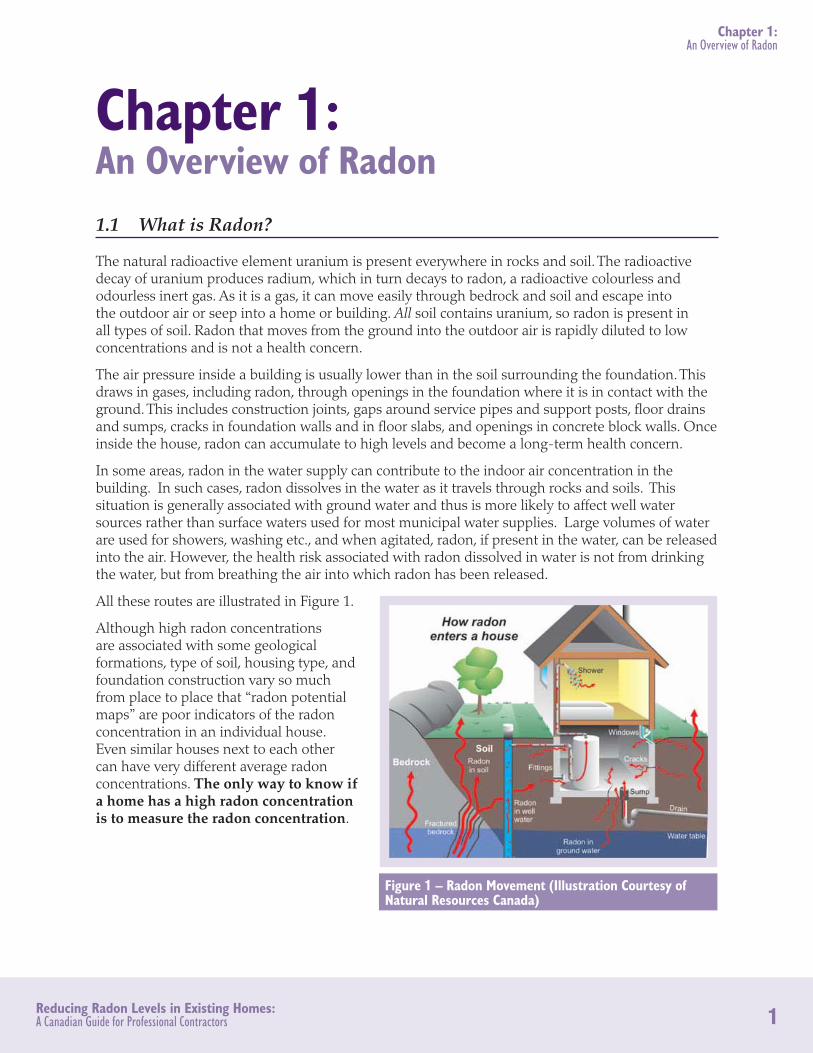
The air pressure inside a building is usually lower than in the soil surrounding the foundation. This draws in gases, including radon, through openings in the foundation where it is in contact with the ground. This includes construction joints, gaps around service pipes and support posts, floor drains and sumps, cracks in foundation walls and in floor slabs, and openings in concrete block walls. Once inside the house, radon can accumulate to high levels and become a long-term health concern.
In some areas, radon in the water supply can contribute to the indoor air concentration in the building. In such cases, radon dissolves in the water as it travels through rocks and soils. This situation is generally associated with ground water and thus is more likely to affect well water sources rather than surface waters used for most municipal water supplies. Large volumes of water are used for showers, washing etc., and when agitated, radon, if present in the water, can be released into the air. However, the health risk associated with radon dissolved in water is not from drinking the water, but from breathing the air into which radon has been released.
All these routes are illustrated in Figure 1.
Although high radon concentrations are associated with some geological formations, type of soil, housing type, and foundation construction vary so much from place to place that “radon potential maps” are poor indicators of the radon concentration in an individual house. Even similar houses next to each other can have very different average radon concentrations. The only way to know if a home has a high radon concentration is to measure the radon concentration.
Figure 1 – Radon Movement (Illustration Courtesy of Natural Resources Canada)

2Reducing Radon Levels in Existing Homes: A Canadian Guide for Professional Contractors
Chapter 1: An Overview of Radon
1.2 Why is it a Health Hazard?
The only known health risk associated with exposure to radon is an increased risk of developing lung cancer. The risk of developing lung cancer depends on:
1. the average radon concentration in the building
2. the length of time a person is exposed
3. their smoking habits
Health Canada estimates a non-smoker exposed to elevated levels of radon over a lifetime has a 1 in 20 chance of developing lung cancer. The combined effects of radon exposure and smoking tobacco significantly increase the risk of lung cancer. If a smoker is exposed to the same level of radon over a lifetime, the risk increases to a 1 in 3 chance.
When a radon atom decays, it emits an alpha particle and produces new elements, called “radon daughters” or “radon progeny”. Two of these progeny, polonium-218 and polonium-214 decay rapidly and also emit alpha particles. When alpha particles hit an object, such as a cell, their energies are transferred to that object, resulting in damage. Human skin is thick enough that the alpha particles cannot penetrate to more vulnerable tissues beneath, but if you breathe in radon or its progeny, the alpha particles they emit can damage unprotected and sensitive bronchial and lung tissues, which can then lead to lung cancer.
Originally, the estimate of lung cancer risk from radon exposure was based on exposures to high concentrations found in uranium mines, and the risk from lower concentrations typically found in homes was uncertain. However, recent residential studies have confirmed that even exposure to the lower radon concentrations found in homes carries a lung cancer risk. The time between exposure and the onset of the disease is usually many years (the average age of onset for lung cancer is age 60). Unlike smoking, besides lung cancer, exposure to radon does not cause other diseases or respiratory conditions nor does it result produce symptoms such as coughing or headaches.
1.3 Radon Guideline
Beginning in 2005, Health Canada collaborated with the Federal Provincial Territorial Radiation Protection Committee (FPTRPC) to review the health risk from exposure to radon. The risk assessment was based on new scientific information and was the subject of a broad public consultation. Using the risk assessment and feedback obtained from the public consultation, the Government of Canada updated its guideline for exposure to radon in indoor air in 2007. This updated guideline provides advice that is more broadly applicable and more protective than the previous FPTRPC guideline.
The current Government of Canada guideline for exposure to radon in indoor air is:
• Remedial measures should be undertaken in a dwelling whenever the average annual radon concentration exceeds 200 Bq/m³ in the normal occupancy area.
• The higher the radon concentration, the sooner remedial measures should be undertaken.

3Reducing Radon Levels in Existing Homes: A Canadian Guide for Professional Contractors
Chapter 1: An Overview of Radon
• When remedial action is taken, the radon level should be reduced to a level or concentration as low as practicable.
• The construction of new dwellings should employ techniques that will minimize radon entry and facilitate post-construction radon removal should this subsequently prove necessary.
For more information about radon and the Guideline, visit the Health Canada Website: www .healthcanada .gc .ca/radon or call 1-800-O-Canada .
4Reducing Radon Levels in Existing Homes: A Canadian Guide for Professional Contractors
Chapter 2: Confirming the Radon Test was Carried Out Properly
Chapter 2: Confirming the Radon Test was Carried Out Properly 2.1 Introduction
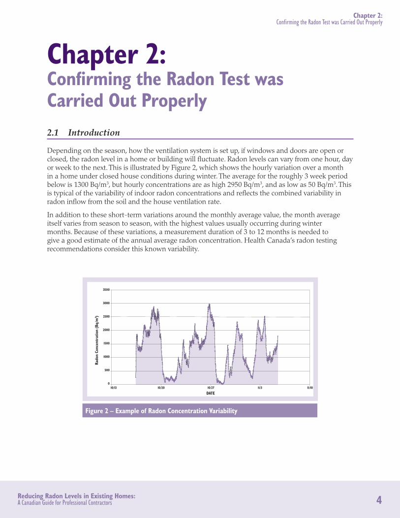
Depending on the season, how the ventilation system is set up, if windows and doors are open or closed, the radon level in a home or building will fluctuate. Radon levels can vary from one hour, day or week to the next. This is illustrated by Figure 2, which shows the hourly variation over a month in a home under closed house conditions during winter. The average for the roughly 3 week period below is 1300 Bq/m3, but hourly concentrations are as high 2950 Bq/m3, and as low as 50 Bq/m3. This is typical of the variability of indoor radon concentrations and reflects the combined variability in radon inflow from the soil and the house ventilation rate.
In addition to these short-term variations around the monthly average value, the month average itself varies from season to season, with the highest values usually occurring during winter months. Because of these variations, a measurement duration of 3 to 12 months is needed to give a good estimate of the annual average radon concentration. Health Canada’s radon testing recommendations consider this known variability.
3500
3000
2500
2000
1500
1000
500
010/13 10/20 10/27 11/3 11/10
Rado
n Co
ncen
trat
ion
(Bq/
m3 )
DATE
Figure 2 – Example of Radon Concentration Variability
5Reducing Radon Levels in Existing Homes: A Canadian Guide for Professional Contractors
Chapter 2: Confirming the Radon Test was Carried Out Properly
2.2 Health Canada Testing Guidance
Long-Term MeasurementsHealth Canada recommends long-term radon testing to determine if the radon concentration exceeds the Health Canada Guideline level of 200 Bq/m3. A test duration of at least 3 months is recommended, and 12 months is optimum. Health Canada does not recommend any test that has duration of less than 1 month.
The long-term radon detectors most commonly used in Canada are:
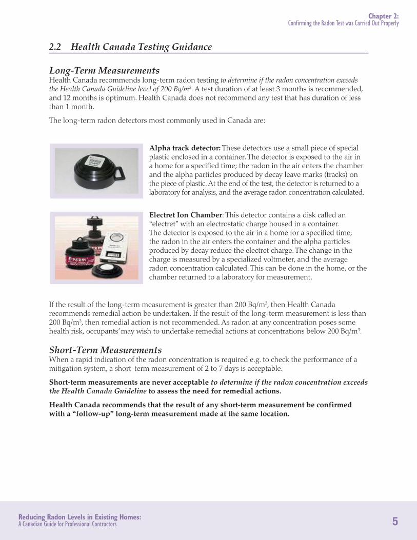
Alpha track detector: These detectors use a small piece of special plastic enclosed in a container. The detector is exposed to the air in a home for a specified time; the radon in the air enters the chamber and the alpha particles produced by decay leave marks (tracks) on the piece of plastic. At the end of the test, the detector is returned to a laboratory for analysis, and the average radon concentration calculated.
Electret Ion Chamber: This detector contains a disk called an “electret” with an electrostatic charge housed in a container. The detector is exposed to the air in a home for a specified time; the radon in the air enters the container and the alpha particles produced by decay reduce the electret charge. The change in the charge is measured by a specialized voltmeter, and the average radon concentration calculated. This can be done in the home, or the chamber returned to a laboratory for measurement.
If the result of the long-term measurement is greater than 200 Bq/m3, then Health Canada recommends remedial action be undertaken. If the result of the long-term measurement is less than 200 Bq/m3, then remedial action is not recommended. As radon at any concentration poses some health risk, occupants’ may wish to undertake remedial actions at concentrations below 200 Bq/m3.
Short-Term MeasurementsWhen a rapid indication of the radon concentration is required e.g. to check the performance of a mitigation system, a short-term measurement of 2 to 7 days is acceptable.
Short-term measurements are never acceptable to determine if the radon concentration exceeds the Health Canada Guideline to assess the need for remedial actions.
Health Canada recommends that the result of any short-term measurement be confirmed with a “follow-up” long-term measurement made at the same location.

6Reducing Radon Levels in Existing Homes: A Canadian Guide for Professional Contractors
Chapter 2: Confirming the Radon Test was Carried Out Properly
In summary, here are a few questions to assess the quality of a radon measurement:
1. Was the measurement taken over a time period representative of the annual exposure of the occupants (from 3 to 12 months)? A short-term measurement can overestimate or underestimate the occupants’ annual exposure.
2. Did the measurement take place during the heating season between October and April? If not, the result could underestimate occupants’ annual exposure.
3. Was the device location in accordance with the recommendations in Health Canada Guide for Radon Measurements in Residential Dwellings (Homes)? If not, the result may not be representative of the occupants’ exposure.
4. Was the measurement taken recently? The measurement may not be representative if renovations affecting ventilation or occupancy have been performed since the measurement was first made.
5. Is the measurement provider certified by one of the two following independent organizations currently recognized by Health Canada?:
a. National Environmental Health Association (NEHA)
b. National Radon Safety Board (NRSB)
For more information on radon measurement, consult the “Guide for Radon measurement in Residential Dwellings (Homes)” available on the
Health Canada Website: www .hc-sc .gc .ca/ewh-semt/pubs/radiation/
radon_homes-maisons/index-eng .php or call 1-800-O-Canada .
7Reducing Radon Levels in Existing Homes: A Canadian Guide for Professional Contractors
Chapter 3: An Overview of Radon Reduction Systems
Chapter 3: An Overview of Radon Reduction Systems 3.1 How Does Radon Enter a Home?
Radon enters a dwelling as a small component of the soil gas (mainly air low in oxygen) that fills the pores between soil grains. The radon concentration in soil gas depends on the concentration of uranium and/or radium in the soil underneath and around the home. The air pressure in a building is usually lower than the pressure in the soil, and this pressure difference draws soil gas containing radon into the building through every opening in the foundation that connects to the soil.
The rate at which soil gas containing radon enters a building (radon supply rate = Bq/h) depends on:
• the resistance of the ground to gas movement, which is affected by bedrock type, soil type and structure, soil moisture, and freezing;
• the radon concentration in the soil gas;
• the house foundation design and construction;
• the pressure differences between the house and the soil.
The radon concentration in the house depends on the radon supply rate and the rate at which diluting outdoor air enters the house (ventilation rate = m3/h).
3.2 Principles of Reducing Radon Entry
The amount of radon that enters a building can be reduced by decreasing the flow of soil gas through the foundation by:
• eliminating openings to the soil through the foundation;
• decreasing the pressure in the soil beneath the building or beneath a membrane so that soil gas no longer flows from the soil into the building.
If the flow of soil gas through the foundation cannot be reduced, the concentration in the living space of a building can still be reduced by:
• changing the internal air circulation patterns to intercept air containing radon before it enters the living space, and diverting it to the outdoors;
• increasing the ventilation rate in the living space or adjacent spaces to dilute the radon.
In some areas, radon is brought into the building dissolved in well water. Radon in water can be removed either by carbon adsorption or preferably by water aeration. Commercial radon aeration units are available. This document does not cover radon in water mitigation.

8Reducing Radon Levels in Existing Homes: A Canadian Guide for Professional Contractors
Chapter 3: An Overview of Radon Reduction Systems
3.3 Selection of Mitigation Methods
The mitigation method chosen is influenced by the reduction in radon concentration required, the building type, and the costs associated with the method, including the running (energy) costs and the cosmetic aspects of the installation. The degree of access to critical foundation areas will influence how easily the mitigation can be completed, and in turn, the cost. How the basement or foundation area is used by a homeowner can affect their expectations of the installation appearance and the cost. A membrane installation acceptable in an unused crawlspace may not be durable enough for a cellar regularly accessed for laundry and storage. An installation that is acceptable in an unfinished laundry room will require additional finishing work to be acceptable in a finished basement area.
Although it is possible to prevent soil gas and radon entry by reconstructing the entire foundation with poured concrete walls and a floor incorporating anti-radon measures, most owners would not be willing to spend a large amount of money to replace the foundation simply to reduce radon concentrations. Fortunately, this is not necessary, as there are lower cost effective mitigation methods for most types of existing foundations. The features and problems associated with the main foundation types are illustrated and discussed below. The mitigation methods listed in Table 1 and Table 2 at the end of this chapter are those that can be applied at a moderate cost in each foundation type. Each method is discussed in detail in later chapters.
3.4 Masonry Foundations
Foundations with masonry, brick or fieldstone foundation walls present a particular challenge for radon mitigation. They are common in old houses, where the construction methods and standards were different from those used today. The foundation floor can range from bare soil, stone, brick, concrete pavers, or wood panels, to a partial concrete slab poured directly on top of the soil. There are many potential radon entry routes in the floor. The foundation floor area may be subdivided by the footings of internal masonry walls, and each part may need to be treated separately.
The foundation walls may never have had an exterior waterproofing layer installed, or the layer may have cracked or separated from the wall over time. The mortar that fills the multiple joints between the masonry is often cracked or deteriorated, providing many potential soil gas and radon entry routes through the wall. These radon entry routes are illustrated in Figure 3 below.
Figure 3 - Radon Entry Routes for a Masonry Basement or Cellar Foundation

9Reducing Radon Levels in Existing Homes: A Canadian Guide for Professional Contractors
Chapter 3: An Overview of Radon Reduction Systems
Depending on the house layout, there may be areas of exposed soil plus a concrete slab to provide a base for combustion or laundry appliances, and this may require a combination of sub-slab and sub-membrane depressurisation methods. In some cases, both the open soil floor and the foundation walls may need to be covered with a continuous membrane to control radon entry through both surfaces by sub-membrane depressurization.
The combination of multiple potential entry routes, plus poor access, can make forced mechanical basement ventilation attractive as a radon reduction measure, provided airflows from the basement to the living areas can be reduced. Access to the basement is needed to maintain the ventilation system. Closing air paths through the floor, and forced air ductwork and furnace seams may be difficult, particularly if access to sub-floor areas is restricted. Suggested mitigation methods for masonry foundations are summarised in Table 1 at the end of this chapter.
3.5 Hollow Concrete Block Foundations
Basement, cellar and crawlspace foundations with hollow concrete block walls can present a challenge for radon mitigation. They are common in older houses built before mass delivery of concrete became readily available, and in rural areas a long distance from concrete batching plants. Although floor openings are the major soil gas and entry routes, wall openings may supply enough radon to create an elevated radon concentration even after radon entry via the floor is prevented.
The exterior waterproofing layer on the wall may have cracked or deteriorated with time, and is often incomplete at the base of the wall where the blocks rest on the footing. In these cases, there also may be water leakage problems. The blocks themselves are porous, and the mortar does not always completely fill the joints between the blocks, so any opening in the exterior waterproofing layer provides an opening in the outer skin of the wall for soil gas and radon to enter the block cavities.
All the cavities in a hollow concrete block wall are interconnected, so once soil gas and radon enters, it can move freely through the wall interior and enter the house through the pores, cracks and openings in the inner skin of the wall, or through open block cavities at the top of the wall. The point(s) of entry into the house through the inner skin of the walls are often remote from the point of entry from the soil into the wall cavity. Interior block walls have no waterproofing layer, so soil gas and radon can readily enter the wall cavity below the slab where the blocks are in contact with soil. The block cavities at the top of these walls are often left open.
The foundation floor can range from bare soil to concrete pavers, wood panels, a partial concrete slab poured directly on top of the soil, or a complete concrete slab. Where the concrete slab covers the entire floor, possible entry routes are the shrinkage crack where the slab meets the foundation wall, random cracks and joints, plus deliberate openings produced beneath basement baths, showers and toilets, at service entries, plus penetrations by teleposts and interior block or wood wall framing.
Some houses have both a concrete slab plus an area with exposed soil, particularly if the house has been extended. This situation may require a combination of sub-slab and sub-membrane depressurisation methods. In some cases, the block wall cavities will need to be ventilated to achieve low radon concentrations.
Many houses, especially in rural areas, have a ground water management system with a drain tile around the exterior perimeter footing connected to a sump basin inside the basement. The drain

10Reducing Radon Levels in Existing Homes: A Canadian Guide for Professional Contractors
Chapter 3: An Overview of Radon Reduction Systems
provides a direct and easy path for soil gas and radon to enter the basement. These routes of soil gas and radon entry are illustrated in Figure 4.
Closure of the sump with exhaust to the outdoors should be among the first actions considered. In some homes, there may be untrapped floor drains leading to dry wells in the soil, which can also provide a direct and easy path for the entry of soil gas and radon. In these situations, installing water traps or mechanical flapper or duckbill trap seals in the open drains should be among the first actions considered.
The multiple potential entry routes can make forced mechanical basement ventilation attractive as a radon reduction measure, provided airflows from the basement to the living areas can be reduced. Closing air paths through the floor, and forced air ductwork and furnace seams may be difficult. Suggested mitigation methods for concrete block foundations are summarised in Table 1 at the end of this chapter.
3.6 Poured Concrete Foundations
Poured concrete foundation walls are common in modern houses in urban/suburban areas. Most walls are cast in one continuous pour without joints, which makes them air and water tight. Exceptions are cracks caused by settlement, “cold joints” produced when the pour is interrupted, and openings around form ties. These faults are readily visible, and can be closed by standard waterproofing methods.
The most common foundation floor is a full concrete slab, usually cast in one continuous pour when the walls are in place. The slab may have been poured directly on top of the soil, but a sub-slab layer of porous fill is common. Some older houses may have a slab plus an area with exposed soil, particularly if the house has been extended. Where the concrete slab covers the entire floor, possible entry routes are the shrinkage crack where the slab meets the foundation wall, random cracks and joints, plus deliberate openings produced beneath basement baths, showers and toilets, at gaps around service pipes entries, plus penetrations by teleposts and interior wood wall framing. These routes of soil gas and radon entry are illustrated in Figure 5.
Some houses may have a ground water management system with a drain tile around the exterior perimeter footing connected to a sump basin inside the basement. There may be untrapped floor
Figure 4 – Radon Entry Routes for a Hollow Concrete Block Foundation

11Reducing Radon Levels in Existing Homes: A Canadian Guide for Professional Contractors
Chapter 3: An Overview of Radon Reduction Systems
drains leading to dry wells in the soil. These drains provide a direct and easy path for soil gas and radon to enter the basement. Closure of the sump with exhaust to the outdoors should be among the first actions considered. Installing water traps, or mechanical flapper or duckbill trap seals in the floor drains should also be among the first actions considered. Suggested mitigation methods for poured concrete foundations are summarised in Table 2 at the end of this chapter.
3.7 Slab-on-Grade Foundations
Slab-on-grade foundations are found in areas where soil conditions such as near-surface bedrock or high water table are unfavourable for deep foundations. There is no ground water management system associated with these foundations.
There are two common foundation designs. One uses a monolithic concrete slab, thickened and reinforced at the perimeter to support the exterior walls, poured over a layer of fill. Possible soil gas and radon entry routes into the house through the slab include random cracks plus the deliberate openings produced beneath baths, showers and toilets, and at plumbing service entries.
The other design uses a shallow exterior perimeter foundation wall to support the exterior walls, and a concrete slab poured inside the wall over a layer of fill. In addition to the slab openings listed above, this gives a joint where the slab meets the perimeter foundation wall. If the foundation wall is hollow concrete block, the block cavities may be a connection from the soil to the house.
Buildings with forced air heating and cooling systems can have all the distribution ductwork installed above the slab, or have some or all of the ductwork present beneath the slab with either a downdraft or up-draft air handler. When the air handler is on, above-slab ductwork that leaks air to outside the conditioned envelope can cause interior depressurization and increase radon entry through all openings in the slab.
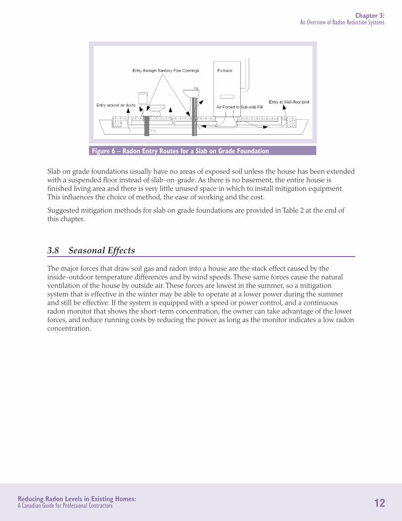
If there is sub-slab return air ductwork, leaky joints will draw soil air and radon from the sub-slab space into the house. If there is sub-slab supply ducting, leakage will cause non-uniform pressurization into the sub-slab space, which may force additional radon into the house via slab openings near the perimeter. When the air handler is off, the sub-slab ducts still provide entry routes via joints in the ductwork, and via openings in the slab where the ducts pass through. These entry routes are illustrated in Figure 6.
Figure 5 – Radon Entry Routes for a Poured Concrete Foundation
12Reducing Radon Levels in Existing Homes: A Canadian Guide for Professional Contractors
Chapter 3: An Overview of Radon Reduction Systems
Slab on grade foundations usually have no areas of exposed soil unless the house has been extended with a suspended floor instead of slab-on-grade. As there is no basement, the entire house is finished living area and there is very little unused space in which to install mitigation equipment. This influences the choice of method, the ease of working and the cost.
Suggested mitigation methods for slab on grade foundations are provided in Table 2 at the end of this chapter.
3.8 Seasonal Effects
The major forces that draw soil gas and radon into a house are the stack effect caused by the inside-outdoor temperature differences and by wind speeds. These same forces cause the natural ventilation of the house by outside air. These forces are lowest in the summer, so a mitigation system that is effective in the winter may be able to operate at a lower power during the summer and still be effective. If the system is equipped with a speed or power control, and a continuous radon monitor that shows the short-term concentration, the owner can take advantage of the lower forces, and reduce running costs by reducing the power as long as the monitor indicates a low radon concentration.
Figure 6 – Radon Entry Routes for a Slab on Grade Foundation

13Reducing Radon Levels in Existing Homes: A Canadian Guide for Professional Contractors
Chapter 3: An Overview of Radon Reduction Systems
3.9 Summary of Mitigation Options
Table 1 – Mitigation Options – Masonry and Hollow Block Foundations
Foundation Type Masonry Hollow Concrete Block
Foundation Floor Exposed soil/pavers Concrete slab Exposed soil/
pavers Concrete slab
Mitigation Options
Close large openings to soil in any accessible parts of foundation walls/floor.
Trap floor drains that lead to soil. Cover soil water drain sump and exhaust it to outside. Isolate foundation area from living area.
Exhaust foundation area air to outside.*
Isolate foundation area from living area.
Install Heat Recovery Ventilator to supply fresh air to living area, and exhaust foundation area air to outside*.
Cover accessible area of exposed soil/pavers with plastic membrane, exhaust from beneath to outside*.
Exhaust from beneath concrete slab to outside*. Close block wall openings to house and exhaust wall cavities to outside*.
* CAUTION Back-drafting of combustion appliances possible. e.g. Wood stove. oil/gas furnace, oil/gas water heater.

14Reducing Radon Levels in Existing Homes: A Canadian Guide for Professional Contractors
Chapter 3: An Overview of Radon Reduction Systems
Table 2 – Mitigation Options – Poured Concrete and Slab-on-grade Foundations
Foundation Type Poured Concrete Slab-on-grade
Foundation Floor Exposed soil/pavers Concrete slab
Exposed soil (building extension)
Concrete slab
Mitigation Options
Close large openings to soil in any accessible parts of foundation walls/floor.
Trap floor drains that lead to soil. Cover soil water drain sump and exhaust it to outside. Isolate foundation area from living area.
Exhaust foundation area air to outside.* Isolate foundation area from living area.
Install Heat Recovery Ventilator to supply fresh air to living area, and exhaust foundation area air to outside*.
Install Heat Recovery Ventilator to supply fresh air to living area, and exhaust from bathroom or furnace area to outside*.
Cover accessible area of exposed soil/pavers with plastic membrane, exhaust from beneath to outside*.
Exhaust from beneath concrete slab to outside*.
* CAUTION Back-drafting of combustion appliances possible. e.g. Wood stove. oil/gas furnace, oil/gas water heater.

15Reducing Radon Levels in Existing Homes: A Canadian Guide for Professional Contractors
Chapter 4: Mitigation by Sub-Slab Depressurisation
Chapter 4: Mitigation by Sub-Slab Depressurisation
4.1 Introduction
In most poured concrete basement houses, the major connections to the soil are through the shrinkage crack where the concrete floor meets the wall, and cracks and service entries in the floor. Soil gas and radon is drawn into the building through these openings. If the pressure in the sub-slab fill is lower than the pressure in the building, airflow will be from the building to the sub-slab fill through these openings, preventing soil gas from entering. If conditions are favourable, a single electric fan drawing on the sub-slab fill can reverse flows over the entire floor slab. The high success rate makes this the “gold standard” of currently available mitigation methods.
4.2 Feasibility Test
A “Pressure Field Extension Test” (or Communication Test) is used to estimate the number of suction points and fan size needed for an effective system. A vacuum cleaner generates a suction field beneath the slab at a proposed suction point, and the extent and size of the suction field is measured with a micro-manometer reading to 0.1 Pa from small test holes drilled near the edge of the slab, and at other locations distant from the suction point location. A convenient and simple temporary high suction fan is a 1.5 kW commercial vacuum cleaner. A choke or bypass in the hose is recommended so that the suction can be adjusted.
Before starting the test, it is important to identify the likely routes of sub-slab plumbing piping to avoid hitting a pipe. It is helpful to identify the internal footing layout, and the location of holes and cracks in the floor. Figure 7 shows the test layout concept.
Figure 7 – Sub-Slab Communication Test

16Reducing Radon Levels in Existing Homes: A Canadian Guide for Professional Contractors
Chapter 4: Mitigation by Sub-Slab Depressurisation
A test exhaust hole large enough to fit the vacuum cleaner hose nozzle (typically ~40 mm diameter) is drilled through the slab into the sub-slab fill at the center of the proposed position of the sub-slab exhaust pipe. If the fill visible through the hole is a large gravel or clear crushed stone, there is a good chance that suction will extend for some distance from the fan, and only one exhaust point will be needed. This also means that the fan will easily pull air from the house through all floor joints, cracks and openings to the gravel fill, and if these connections are left unclosed a larger fan will be needed and the operating cost will be higher. If the fill is comprised of sand or clay, or the slab is poured directly on the ground, the fan suction may only reach a short distance from the fan, and a larger suction pit, or two or more exhaust points may be needed.
WARNINGOnce the drill breaks through the slab, probe the fill to a depth of 15-20 cm to be sure that drilling deeper will not hit a plumbing pipe.
A permanent sub-slab system typically has an excavated suction pit cavity ~25 cm radius, ~15 cm deep, so that the test exhaust hole is drilled to ~15 cm below the slab. A small monitoring hole (8-10 mm diameter to install the pressure sensor, P1 in Figure 7) is drilled ~25 cm from the test exhaust hole and to ~15 cm below the slab. The edge of the suction pit cavity will be at or beyond this point. If the vacuum cleaner suction is adjusted so the suction at the test hole is comparable to the suction a permanent fan can produce, then the suction near the slab edge will be similar to that produced by a permanent fan.
Small test holes (8-10 mm diameter to install the pressure sensor, P2 in Figure 7) are drilled through the slab in the corners of the foundation at 20 to 40 cm from the exterior walls of the building to avoid the footings. In carpeted areas, corners can be peeled back with needle nosed pliers to access the floor slab. Each hole is temporarily plugged with putty after it is drilled, and all holes are closed with a quickset cement plug when the tests are complete.
When all holes are drilled, the vacuum cleaner is connected to the test exhaust hole, and the suction adjusted so that the suction at the monitoring hole (P1) is no greater than that produced by a fan (-100Pa to -250 Pa). The pressure at each test hole is measured with the vacuum cleaner on and off. If there is a pressure change at each test hole, the proposed suction point location for the sub-slab system is feasible. If there is no pressure change at some holes, look for air leaks through the floor near or between the suction point and the test hole, and seal temporarily to close them (putty or rope caulk or duct tape is useful). If this does not give a pressure change, drill more test holes to determine if suction is blocked by internal footings interrupting the sub-slab fill. If there are no footings, the fill under the slab may have high resistance to air movement.
Internal footings are located beneath internal load bearing walls. If the pressure change is high in test holes on the vacuum cleaner side of the footing, and low or zero on the other side, then the footing divides the sub-slab space into two or more sections, and more than one suction point may be needed to cover the floor slab. If this is the case, the tests are repeated with exhaust test holes at additional proposed suction point locations.

17Reducing Radon Levels in Existing Homes: A Canadian Guide for Professional Contractors
Chapter 4: Mitigation by Sub-Slab Depressurisation
If the sub-slab fill is not gravel or clear crushed stone, the fill is likely to have a high resistance to airflow, and there may be no pressure change at distant test holes. In this case, additional test holes are drilled at intervals closer to the test exhaust location, until a hole is found with a measurable pressure change. The distance to this hole is an indication of the effective radius of the suction point. A large suction pit will increase that radius, but additional suction points should be planned at about twice the effective radius apart, and the test repeated at each proposed location in turn to confirm that together they will provide coverage of the entire foundation area.
In soils and fills with high resistance, suction points near a wall often give a suction field that reaches further along the wall than from a suction point located near the centre of the slab. The soil near the footings is disturbed during construction, and often has a lower resistance to airflow than the undisturbed soil beneath the centre of the slab. There is often a small gap between the top of the footing and the lower surface of the slab, which allows the suction to spread along the foot of the wall. The wall/floor joint is a major entry route, and suction in this area is important to reduce radon entry.

18Reducing Radon Levels in Existing Homes: A Canadian Guide for Professional Contractors
Chapter 4: Mitigation by Sub-Slab Depressurisation
Example 1: Feasibility Test
Figure 8 below shows exhaust and test hole locations in a house with a partially finished basement. The family room and bedroom have walls and ceiling covered with plasterboard, the floors are carpeted, and the bathroom floor is tiled. The utility room is unfinished. There is no sump for groundwater control, and the floor drain connects to the sewer.
As there are no direct connections from the house to the soil, a sub-slab exhaust system alone may reduce radon concentrations. There are probably slab openings around the sewer connections beneath the bath and toilet. Performance of the system will be better if these openings are closed when the permanent system is installed.
The preferred location for the exhaust point and fan based on cost and appearance is in the unfinished utility room, either at locations A or B, depending on the ease of the pipe run to the outside. The first test hole is drilled at C. If pressure change is present there, the next test holes are drilled at D, E and F. If a pressure change can be measured at all these holes, then a single suction point system in the utility room is feasible.
If there is no pressure change at D, E and F, then the internal walls may have footings that effectively partition the sub-slab fill into two or three compartments. This would be confirmed by no or small pressure changes at test holes G and H. The test is then repeated with suction applied at locations G and H to see if suction at these locations would extend to locations D, E, and F at the other ends of the room. If desired, a drywall chase could be constructed around the suction pipes at H and/or G to preserve the appearance of these rooms.
.
Photo 1 – Feasibility Test
Test hole (P2)
Monitoring hole (P1)
Test exhaust hole
Industrial Vaccum Cleaner
Figure 8 - Test Hole Layout Example

19Reducing Radon Levels in Existing Homes: A Canadian Guide for Professional Contractors
Chapter 4: Mitigation by Sub-Slab Depressurisation
4.3 System Design
General In most moderate size houses with granular fill beneath the floor slab, and no large air leaks into the sub-slab fill from the house or outdoors, a 40 to 60 watt “radon fan” will be large enough to produce the needed flows and pressures to effectively reverse the flow of soil gas from in to out of the house. However, if the house footprint is large, there are inaccessible openings in the floor slab, the soil highly porous, the sub-slab fill divided by footings, or the fill has high resistance to air movement; a higher power “radon fan” with larger flow or suction capacity may be needed. The following sections provide the background information necessary to carry out the additional tests needed to calculate the size and type of fan needed. Not all installations will need a full system design as shown in this example; experience can indicate which fans will be satisfactory in an area after making just a few sub-slab pressure measurements.
Building Pressure DifferencesThe pressure in a building is lower than the pressure outdoors due to the temperature difference between inside and outside, and wind pressures. The temperature difference (stack effect) is the major driving force. The difference between the pressure at ground level outside the house, and the stack effect pressure just above the floor slab for Canadian conditions is shown in Table 3 Building Exterior-Interior Pressure Differences (Stack Effect). When there is no wind, this is the total driving force to move soil gas into the building. Part of the pressure difference drives the soil gas through the soil to the sub-slab space, and the remaining pressure difference drives the soil gas into the house through cracks and openings in the slab. Wind pressures acting on the building and soil, and operation of systems like kitchen or bathroom exhaust fans and clothes dryers will increase the pressure difference.
Example 2: Building Pressure Differences
From Table 3, in a 2-storey house in winter, the total outside-inside pressure difference may be -8 Pa, made up of a pressure difference across the soil of -7 Pa, and a pressure difference across the slab of -1 Pa, caused by the resistance of the slab openings to the flow of soil gas from soil into the house.
If the fan draws more soil gas from beneath the slab than the house drew, the sub-slab pressure will then be lower than the house pressure, reversing the flow. The lower the natural pressure difference across the slab, the larger are the slab openings, and hence correspondingly higher fan flows will be needed to reverse the flow.

20Reducing Radon Levels in Existing Homes: A Canadian Guide for Professional Contractors
Chapter 4: Mitigation by Sub-Slab Depressurisation
aTable 3 – Building Exterior-Interior Pressure Differences (Stack Effect)
Maximum Pressure Difference Across Below-Grade Building Envelope (Pa)
House Type Mild Winter Moderate Winter Severe Winter
Slab on grade (no chimney) 1 2 3
Slab on grade (chimney) 3 4 5
1 or 2 Storey (no chimney) 4 5 6
1 or 2 Storey (chimney) 8 9 10
3 Storey (no chimney) 7 8 9
3 Storey (chimney) 13 14 15
Data from CMHC Estimating the Concentrations of Soil Gas Pollutants in Housing 1997
The pressure differences are the highest when the indoor-outdoor temperature differences are the greatest i.e. mid-winter. The across-slab pressure difference at that time is the highest, and the sub-slab system must be designed to reduce the difference to at least zero. The suction needed to do this is the Design Suction. The Design Suction can only be estimated directly from the across-slab pressure difference measurement in mid-winter. The effect of seasonal weather (exterior temperature) on pressures for a two-storey house located in a severe winter area is illustrated in Table 4. The natural across-slab pressure difference in winter is 1 Pa. In contrast, the across-slab pressure difference in spring or fall is only 0.4 Pa, 40% of the maximum value in winter. To estimate the Design Suction, the measured natural pressure difference has to be adjusted to take into account the difference between the outdoor temperature at the time of measurement and the minimum outdoor temperature. Suggested temperature adjustment factors are given in Table 5.
Fan Flow EstimateThe Design Suction will be produced by a permanent “radon fan”, but the vacuum cleaner will not produce the same airflows and sub-slab pressure drops. This section illustrates the calculations to estimate the required permanent fan airflow and the size and model of fan needed.
EquipmentA flow measurement device is required to measure the airflow through the vacuum cleaner nozzle. It can be an orifice with a pressure gauge to measure the pressure drop, or a straight section of pipe with an opening for a pitot tube or hot-wire anemometer probe.
A choke or bypass in the hose, downstream of the airflow measurement device is recommended so that measurements can be made at two flow rates.
NOTE: Debris in the air from under the slab can plug a pitot tube and damage sensitive measuring devices. An orifice is unaffected by debris.
The pressure in the suction nozzle during a measurement can be many kPa lower than atmospheric, and some measuring devices may need an air density correction applied to their reading. The nozzle calibration should be checked against a standard flow device in free air.

21Reducing Radon Levels in Existing Homes: A Canadian Guide for Professional Contractors
Chapter 4: Mitigation by Sub-Slab Depressurisation
ProcedureWhen a satisfactory suction point location has been identified by the feasibility test, the sub-slab pressure change is measured relative to the house at the monitoring hole (P1, Figure 7) and at the hole that had the lowest pressure change (P2, Figure 7) during the feasibility test. The flow measurement device is attached to the vacuum cleaner nozzle, the vacuum cleaner is turned on, and the flow out of the sub-slab space is measured = “Q (L/s)”. At the same time, the pressure relative to the house is again measured at P1, and P2.
The Design Suction is estimated from the change in pressure difference measured at P2.
The permanent fan flow needed to give the Design Suction is estimated from the measured vacuum cleaner flow rate multiplied by the ratio of the Design Suction to the pressure change measured at the hole with the lowest observed drop.
NOTE: This assumes flow near the slab edge and fan flow are linearly related. The relationship can be checked for the slab if P2 is measured at two different flow rates.
Table 4 – Example of House and Sub-slab Differential Pressures
Example Two Storey House Differential Pressures (Pa)
SeasonLocation
A B C Across-slab (B-C)
Severe Winter 0 -9.0 -10.0 +1.0
Mild Winter 0 -7.2 -8.0 +0.8
Spring/Fall (estimated) 0 -3.6 -4.0 +0.40
Summer (estimated) 0 0 0 0
Data from CMHC Estimating the Concentrations of Soil Gas Pollutants in Housing 1997

22Reducing Radon Levels in Existing Homes: A Canadian Guide for Professional Contractors
Chapter 4: Mitigation by Sub-Slab Depressurisation
Table 5 – Design Suction Temperature Adjustment Factors
Suggested Adjustment Factor for Design Suction versus Exterior Temperature
Exterior Temperature during Test Winter Climate Zone
Mild Moderate Severe
>0 °C 2.0 2.2 2.5
0 to -10 °C 1.4 1.5 1.6
-10 to -20 °C 1.0 1.0 1.2
< -20 °C 1.0 1.0 1.0
Example 3 - Fan Calculation
Design Suction:
Measurements are made in mid winter in a two-storey house in a severe winter area. The pressure differential across the floor slab near the slab edge at P2 is +3.3 Pa, relative to inside the house. To neutralise this pressure, the exhaust fan must produce an equal suction at P2.
The Design Suction is therefore -3.3 Pa relative to the house. The Design Airflow is the airflow required to produce this suction.
Design Airflow Calculation:
Observed vacuum cleaner flow rate Q = 16.7 L/s
Pressure differential at P2 with vacuum cleaner on = +1.2 Pa relative to house – a change of -2.1 Pa.
To reduce the sub-slab pressure from 3.3 Pa to zero, the permanent fan airflow (Design Airflow) must be higher than the vacuum cleaner test airflow of 16.7 L/s.
Design Airflow = (Design Suction/Pressure change measured at P2) x Vacuum Cleaner Flow
(Q) = (3.3 Pa/2.1 Pa) x 16.7 L/s = 1.6 x 16.7 L/s = 26.7 L/s.
This is the airflow the system must produce to give a sub-slab suction of 3.3 Pa at the slab edge.
Estimate of System Pressure Drops
Sub-Slab Material Pressure Drop
When a sub-slab depressurisation fan is in operation, most of the pressure drop in the sub-slab fill is near the suction pipe entry, where the flow velocities are highest. To reduce this, a suction pit cavity roughly 50 cm in diameter, and 15 cm deep is excavated in the fill and soil beneath where the suction pipe penetrates the slab. If the fill is large stone or gravel, and the soil porous, the pit need not be as large, but if there is no fill, and the soil is sand or clay, the pit should be as large and as deep as feasible.
The suction in the cavity needed to give the Design Airflow is the Cavity Suction, estimated from the suction produced by the vacuum cleaner at the monitoring hole P1, multiplied by the square of the ratio of the Design Airflow and test flow (Q).

23Reducing Radon Levels in Existing Homes: A Canadian Guide for Professional Contractors
Chapter 4: Mitigation by Sub-Slab Depressurisation
NOTE: Pressure drop normally depends on the square of the flow rate. The relationship can be checked if the pressure at P1 is measured at two different flow rates.
Example 4 - Cavity Suction
Measured pressures (relative to inside the house) at cavity radius P1 with vacuum cleaner off/on = +3.3 (off); -11.6 Pa (on). Pressure change = -11.6 Pa – 3.3 Pa = -14.9 Pa. This is sub-slab suction at the monitoring hole P1 location (= planned cavity edge) at vacuum cleaner flow of 16.7 L/s.
Estimated suction at cavity edge at Design Airflow 26.7 L/s = Suction at the monitoring hole P1 x (Design Airflow/Q)2
= -14.9 Pa x (26.7 L/s/16.7 L/s)2 = -38 Pa.
The fan must be able to produce this suction in the cavity to give the Design Airflow through the sub-slab fill, and the Design Suction at the slab edge.
Often a 20-30 cm diameter opening is cut in the slab to ease excavation of the sub-slab fill and soil. In this case, the cavity is filled with 25 mm clear stone to the lower side of the slab to support the exhaust pipe and concrete used to close the opening. Alternatively, an inverted pipe “T” is placed in the cavity to support the pipe, and the cavity filled with 25 mm clear stone to support the concrete used to close the hole. A sheet of plastic is placed over the stone to keep the concrete out of the stone voids. If the fill and soil is small stones and gravel, the material can be loosened by a probe, and removed with the vacuum cleaner through a small hole comparable to the pipe diameter. In this case, the pipe can be supported on the floor slab by a coupling or reducer, and the gap filled with caulk. These details are illustrated in Figure 9.
Piping System Pressure DropThe pressure drop in the sub-slab fill is not the only pressure drop that the fan must overcome. The piping to and from the fan also contributes a resistance to airflow. The pressure drop in the piping system is estimated from the air velocity through the system, the number of elbows, and the length of the piping.
The Dynamic Head (Vp) is the pressure required to produce an air velocity in a pipe, and is given by Vp = 0.6 V2, where Vp is in Pa, and the velocity V is in m/s.
Approximate pressure drops in piping are:
• in a “T” 1 Vp • in a 45° elbow 0.5 Vp • in a 90° elbow 1 Vp • frictional drop in PVC pipe is 1 Vp per 4 m. • drop through the coarse stone filling the cavity is estimated as 2 Vp.

24Reducing Radon Levels in Existing Homes: A Canadian Guide for Professional Contractors
Chapter 4: Mitigation by Sub-Slab Depressurisation
Figure 9 – Exhaust Pipe Connection Details
Example 5: Piping Pressure Drop Calculations All piping in the system is 100 mm diameter PVC. There is a 100 mm “T” in the sub-slab cavity, 1 m of pipe to the fan including two 45° elbows, and 11 m of exhaust pipe from the fan including two 90° elbows and two 45° elbows. At a flow of 26.7 L/s, the velocity through the system is 3.4 m/s, with a dynamic head (Vp) of 7.0 Pa.
Table 6 shows the estimated pressure drops in the piping for the various components.

25Reducing Radon Levels in Existing Homes: A Canadian Guide for Professional Contractors
Chapter 4: Mitigation by Sub-Slab Depressurisation
Table 6 – Piping Pressure Drop Calculations
Piping Pressure Drop Estimates
ComponentUnits Dynamic Head (Vp)
Component Loss Coefficient Actual Dynamic Head LossCavity Fill 2 2.01 x Tee 1 1x1 =1.02 x 45° elbow 0.5 2x0.5 = 1.01 m pipe 0.25/m 1x0.25 = 0.25
Total Loss in pipe to fan 4 .25 Vp2 x 45° elbow 0.5 2x0.5 =1.02 x 90° elbow 1 2x1 = 2.011 m pipe 0.25/m 11x0.25 = 2.75Discharge to atmosphere via rodent grille
3 1x3 = 3.0
Total Loss in Pipe from Fan 8 .75 VpTotal Dynamic Head Loss in system 13 VpTotal piping Pressure Drop at 26 .7 L/s, (Vp = 7 Pa) 13 Vp = 13 x 7 Pa = 91 Pa
SummaryTo produce the Design Flow of 26.7 L/s, the pressure difference across the fan must equal the pressure drops in the sub-slab material resistance, the piping resistance, and the pressure drop between the inside of the house and outside. The fan draws air from inside the house, but discharges to the outside, and has to overcome the house /outside difference. The total system pressure drop from basement slab edge to atmospheric discharge is the sum of all the system pressure differences. At a flow of 26.7 L/s, these are: 38 Pa from sub-slab fill resistance (from Example Sub-slab Pressure Drop Calculation) plus 91 Pa from piping resistance (from Table 6) for a flow related total of 129 Pa. There is also the constant severe winter indoor-outdoor pressure difference of 10 Pa (see Table 3). The total system pressure drop from slab edge to atmospheric discharge at a flow of 26.7 L/s is therefore estimated at 139 Pa. The pressure difference at any other flow rate “F (L/s)” can be estimated as = 129 x (F/26.7)2 +10 Pa.
Fan SelectionThe fan Design Point is 26.7 L/s at 139 Pa. The fan manufacturers provide tables of pressure across fan versus flow rate, but it is rare that the design point will coincide with a tabulated value. A graphical solution is the easiest way to select a fan. The values of fan pressure versus flow rate given in the table are plotted on a graph, and the system pressure difference versus flow rate is plotted on the same graph. Where the two lines intersect is the flow rate and pressure that the fan will produce in the system – the Operating Point.
Figure 10 shows an example of a graphical solution.
The pressure versus flow curves of two radon mitigation fans are shown, plus the system pressure versus flow curve (in green) as calculated above. Fan 1 (in blue) is one of the smaller capacity fans on the market @37 L/s free flow; fan 2 (in red) is a medium capacity fan @57 L/s free flow. Note that the

26Reducing Radon Levels in Existing Homes: A Canadian Guide for Professional Contractors
Chapter 4: Mitigation by Sub-Slab Depressurisation
fan curves cross at approximately 250 Pa. At higher pressure differences, fan 1 moves more air than fan 2, and so a choice between fans cannot be made solely from the free airflow values.
The fan and system curves intersect at 31.5 L/s, 190 Pa for fan 1, and at 34 L/s, 230 Pa for fan 2. Both these operating points are well above the design point, so either fan would be effective, but the smaller fan is preferred (fan 1). It will be quieter, use less electricity, and still has a 10% flow margin in excess of the design point to allow for measurement uncertainties.
Only a few installations will need a full system design as shown in this example; experience can indicate which fans will be satisfactory after making just a few sub-slab pressure measurements.
0
10
20
30
40
50
60
0 50 100 150 200 250 300 350 400
FLO
W R
ATE
(L/
s)
PRESSURE DIFFERENTIAL (Pa)
FAN SELECTION CHART
OPERATING POINT FAN 2 34 L/s 230 Pa
OPERATING POINT FAN 1 31.5 L/s 190 Pa
DESIGN POINT 26.7 L/s 139 Pa
Fan 1 Pressure vs Flow Curve
Sub slab exhaust systemFlow vs Pressure Curve
Fan 2 Pressure vs Flow Curve
Measurements in other seasonsIn the examples above, the measurements were made in mid-winter, when the measured pressure differences were the highest, and could be used directly to estimate the Design Suction and Flow. The following example shows how to use Table 5 to adjust measurements made in other seasons.
Figure 10 – Fan Selection Graphical Solution

27Reducing Radon Levels in Existing Homes: A Canadian Guide for Professional Contractors
Chapter 4: Mitigation by Sub-Slab Depressurisation
Example 6 - Seasonal Correction Measurements are made in the late fall in a house located in a severe winter area. The outdoor temperature is 2°C. The natural pressure differential measured across the floor slab at P2 is +1.3 Pa, relative to inside the house. Table 5 suggests that during severe winter weather, the natural pressure differential will be 2.5 times higher, 2.5 x 1.3 Pa = 3.3 Pa. The Design Suction is therefore = -3.3 Pa relative to the house.
Observed vacuum cleaner flow rate Q = 16.7 L/s. Pressure differential at P2 with the vacuum cleaner on = -0.8 Pa relative to house – a reduction in sub-slab pressure of 2.1 Pa.
To give a suction of -3.3 Pa, the permanent fan airflow must be 1.6 = (-3.3 Pa/-2.1 Pa) times higher than the vacuum cleaner airflow of 16.7 L/s.
Design Airflow = (Design Suction/Pressure change measured at the hole with the lowest observed drop) x Q = 1.6 x 16.7 L/s = 26.7 L/s.
The Design Suction and Airflow values are the same as those in the previous example, and the calculation of fan size is the same.

28Reducing Radon Levels in Existing Homes: A Canadian Guide for Professional Contractors
Chapter 4: Mitigation by Sub-Slab Depressurisation
Sub-slab system installation examples
Photo 2 – Attic Fan Installation
Photo 3 – Basement Fan Installation
Photo 4 – Two Suction Point System

29Reducing Radon Levels in Existing Homes: A Canadian Guide for Professional Contractors
Chapter 5: Mitigation of Exposed Soil
Chapter 5: Mitigation of Exposed Soil
5.1 Introduction
Older houses often have areas of exposed soil inside the foundation, particularly if the house has been extended. The soil provides an entry route for radon and soil gas. The distance from the soil to the building floor above can range from >2 m in basements/cellars to <30 cm in extensions.
There are two approaches to reducing the radon concentration directly above the soil; ventilation, where the airflow through the space is increased to dilute the radon that enters, or reducing the radon entry rate by placing a cover over the soil and exhausting the soil gas and radon from beneath it before they enter the house. Ventilation is discussed in Chapter 7, while the next section deals with covering the soil and exhausting the airspace between the soil and cover.
5.2 Sub-membrane Depressurisation
A durable and airtight cover for soil is a concrete slab. A slab poured over exposed soil with porous fill beneath, plus a standard sub-slab depressurisation system will be an effective soil gas collector. However, concrete is expensive, and difficult to install in areas where access and headroom is limited. An alternative to concrete is a flexible membrane. This can be manoeuvred into areas where headroom is low and spread over the soil. Perforated piping or porous material is placed on the soil to ensure the fan suction is distributed to the edges of the membrane and acts as the gas collector. The membrane is attached to the foundation walls. Seams where sheets overlap, the wall perimeter, penetrations, and tears are all sealed to reduce the amount of air drawn from the house. The piping is brought out through the membrane and connected to a fan to discharge the collected soil gas and radon outdoors. Special attention is needed to seal around the pipe where it penetrates the membrane.
The membrane material must be strong enough to withstand the traffic during installation without damage, and be available in large sheets to limit the number of joints or overlaps needed. (Any damage during installation must be repaired immediately). Depending on the expected traffic, suitable membranes range from:
• 0.08 mm two ply laminated high density polyethylene;
• laminated high density polyethylene reinforced with a polyester or fibreglass scrim;
Photo 5 – Sealing the penetration through the membrane

30Reducing Radon Levels in Existing Homes: A Canadian Guide for Professional Contractors
Chapter 5: Mitigation of Exposed Soil
• polyolefin reinforced with nonwoven textile;
• up to 1 mm polypropylene or EPDM sheets as used in roofing.
Joining tape is available for all of these, and pipe and corner flashings are available for polypropylene and EPDM. The thicker sheeting and protective mats should be installed when crawlspaces are used for storage or frequent entry is required for maintenance of utilities.
Although the soil surface is often uneven enough that air can flow beneath the membrane, the suction field can be made more uniform by using permeable matting, beds of large clean aggregate, or additional perforated piping under the membrane. This piping does not have to conform to any particular diameter or wall thickness. The crush strength is important only if the area has foot traffic or is used for storage.
The membrane is run about 100 to 300 mm up each wall, caulked to the wall, and secured in place with decay and insect resistant battens fixed with masonry fasteners. Caulking and construction adhesives may be used to fix the membrane in place during installation, but it is important to know the compatibility of adhesives with the membrane material and their tolerance to dirt on the wall surface. Many do not form a strong enough bond between old concrete and membrane materials (particularly polyethylene) to be a reliable long-term attachment method. It is important that there be some slack in the material at the edges, as the suction will pull the membrane down snug to the floor against any restraints. Figure 11 and Picture 6 illustrates how the membrane is installed and attached to the wall.
If there are no supports or service piping in the space, the membrane can be installed in one piece with the exhaust pipe brought out via a cut opening sealed with a pipe flashing. If there are supports or pipes in the space, the membrane must be slit to pass around these items and it may be more convenient to install it in several pieces. The seams should be lapped at least 300 mm and caulked with an adhesive caulk. A collar is cut from the material to fit around each penetration and attached and caulked to the penetration. The membrane is then caulked to the collar. If water is likely to collect on the membrane, it shall be fitted with trapped drains at the lowest part of the locations that are likely to become wet.
Figure 11 – Membrane and Wall Attachment Photo 6 – Membrane and Wall Attachment

31Reducing Radon Levels in Existing Homes: A Canadian Guide for Professional Contractors
Chapter 5: Mitigation of Exposed Soil
Typically, the membrane is two pieces of material cut to size and shape (including allowance for overlaps) outside the house, folded, and brought into the crawlspace. It is unfolded there, and placed over a perforated exhaust pipe run in a perimeter loop, around building support footers and a sanitary stack. It is first attached to the walls, and then all overlaps, patches and collars are caulked. The system exhaust pipe is brought out through a hole cut in the membrane. Thorough sealing of this penetration through the membrane is critical; a leak here will reduce the effectiveness of the installation. One technique is to use two vinyl roof soil stack flashings, one under the membrane and one above the membrane, caulked to form an airtight seal.
If soil is exposed in several sections of the foundation, a separate membrane is required for each section. The exhausts can be combined so that one fan deals with all sections (photo 5).
5.3 Sizing the System Fan for Sub-membrane Depressurization
The criterion for best performance is that the pressure beneath the membrane is less than the pressure in the space above the membrane. This ensures that the airflow through every joint and opening is from the house to beneath the membrane. Leaks are common at irregularities in the wall, wrinkles across seams, and folds in the sheet at corners - all of which provide channels to bypass the caulking.
The leakage area of the membrane is very dependent on the quality of the seal to the wall, and a leak survey should be carried out before sizing the permanent fan. The vacuum cleaner is attached to the exhaust pipe, and the membrane is depressurised. (Pressurising beneath lightweight membranes is not recommended, as it may lead to the membrane ballooning – and opening caulked joints). Some leaks can be heard, others can be found by observing the movement of chemical smoke (photo 7). Additional caulk or caulked patches will close the leaks.
Only a few installations will need a full system design, as experience can indicate which fans will be satisfactory after making just a few pressure measurements on the membrane. If fan selection is needed, the vacuum cleaner can be attached to the exhaust pipe, and the flow rate and pressures beneath the membrane measured, preferably at two different flow rates. The required flows and fan size can be calculated from these values, using the methods illustrated in Chapter 4.
Photo 7 – Use of chemical smoke

32Reducing Radon Levels in Existing Homes: A Canadian Guide for Professional Contractors
Chapter 6: Mitigation by Sump and Drainage System Depressurization
Chapter 6: Mitigation by Sump and Drainage System Depressurization 6.1 Introduction
A groundwater drain system (weeping tile) is installed around basements to prevent soil water pooling against the walls and leaking into the basement. The weeping tile is a perforated pipe around the exterior of the foundation at footing level. Depending on the locality, basement window wells and roof downspouts may also be connected to the weeping tile. The collected water may drain to a sump basin inside the building where a sump pump discharges the water on the site surface away from the house, or directly to a storm drain sewer.
The weeping tile acts not only as a water collection system, but is also an efficient collector of soil gas while the soil is not saturated with water. In cold climates, the soil is unsaturated for most of the winter. If the tile connects to a sump basin inside the house, this is an easy entry route for soil gas and radon. There may be other radon supply routes into the house, but low radon concentrations are rarely achievable until this route is closed.
6.2 Closing a Sump System
Any action to close this entry route must prevent soil gas and radon from entering the house, while still allowing water to enter the sump and be pumped away. A cover over the sump pit, sealed to the concrete floor slab, with airtight seals around the sump pump wiring and discharge pipe will close the direct route into the house. However, this action by itself will not prevent soil gas and radon from entering via other connections to the soil.
Attaching an exhaust fan to depressurize a covered sump basin will collect soil gas from the weeping tile system, and draw air from the sub-slab aggregate through the side openings in the sump basin. Depending on the construction details, this may be enough to act as an effective sub-slab depressurisation system. Similarly, a sub-slab depressurisation system with a suction point near a covered sump will also collect soil gas from the weeping tile via these connections.
Depressurising the sump basin reduces the pressure in the exterior weeping tile, and lowers the pressure in the exterior soil, reducing the soil gas entry rate to the building. This can be important in the case of concrete block basement walls where there are often entry routes into the wall from the soil at the footing level. An example of a sump depressurisation installation is shown in Figure 12. Sump pit covers are typically made of durable plastic or other rot-resistant rigid material, designed to permit airtight sealing and to support the weight of a 70 kg person standing on the cover. Penetrations of sump covers for electrical wiring or for a water discharge pipe should be designed to permit airtight sealing around them using rubber grommets or silicone caulk. The cover should

33Reducing Radon Levels in Existing Homes: A Canadian Guide for Professional Contractors
Chapter 6: Mitigation by Sump and Drainage System Depressurization
be sealed to the concrete floor slab using silicone or other non-permanent type caulking materials or mechanically fastened with an airtight compression gasket. Covers should incorporate a view port or allow access to permit observations of conditions within the sump pit. A submersible sump pump can be installed, with unions on the water discharge pipe above and below the cover to ease removal. In addition, either the sump pump or its discharge pipe should incorporate a check valve to keep outside air from flowing through the pump when the basin is dry. If exhaust piping is connected to the sump cover, the piping should include rubber couplings to ease removal of the cover for sump pump maintenance.
A sump cover can be fabricated, but there are commercially available plastic “radon sump covers“, and complete “radon sump basins”, with these connections built into the sump lid and liner. It will generally be cost-effective to install one of these units.
Floor DrainsIf a basement floor drain is connected to the sump, a mechanical trap seal device or water trap should be installed to prevent house air from entering the sump via the drain. If the basement floor is graded so that an open sump pit acts as the floor drain system, and the sump cover can be made flush with the floor slab or lower, it should include a water trap or a mechanical airflow control drain. If the cover is above the floor slab, a drain with a water trap or other airflow control device should be installed in the concrete floor and connected to the sump pit.
Figure 12 – Sump Exhaust
Sizing the sump system fanThe size of fan needed to give satisfactory results is estimated by placing a temporary cover over the sump and exhausting with the vacuum cleaner while measuring pressure drop in the sump and the exhaust flow (preferably at two different flows). At the same time, the pressure drop in the sub-slab space is measured through small holes drilled through the slab at points near and remote from the sump. The ratio of these pressure drops shows how well the openings in and around the sump connect to the sub-slab space, and indicates the resistance of the sub-slab fill to air movement. If the

34Reducing Radon Levels in Existing Homes: A Canadian Guide for Professional Contractors
Chapter 6: Mitigation by Sump and Drainage System Depressurization
airflow from the tile is low, and the connection to the sub-slab fill is good, ventilating the sump can also provide sub-slab depressurisation and further reduce radon entry. The size of fan needed to give a satisfactory sub-slab pressure drop can be calculated using the same methods shown in Chapter 4.
If the test shows a large flow from the sump at a small pressure drop, air may be coming from downspouts or window wells drained to the weeping tile. This can be confirmed by visual inspection, or by pouring water down suspected connections to see if it appears in the sump. If there are surface connections, sump depressurisation will draw cold air down in the winter with a danger of freezing the ground. To prevent this, downspouts should be re-routed to discharge at ground level away from the house and the connections closed. Window well drains can not be closed without a risk of basement flooding. It may be possible to attach a mechanical trap to the window well drainpipe, some units will remain closed against up to ~250 Pa suction, but still open to allow water to drain. Covering the drain openings with filter cloth and sand will reduce airflows but still allow water to drain.
Sub-slab depressurisation and sumpsIf the sump basin is covered and sealed, a sub-slab depressurisation system can still reduce radon entry into the house. The feasibility study (see Chapter 4) should be carried out with a temporary cover over the sump sealed to the floor. In many cases, the best location for the suction point will be near the sump.
6.3 Using Perimeter Foundation Drains
Even if the weeping tile is not brought into a sump, but rather discharges by gravity to the surface on a sloping site, it can still be used as part of a soil gas and radon reduction system. A fan attached directly to the weeping tile lowers the pressure in the soil near the major entry routes, and diverts soil gas from entering the building. This is important in the case of concrete block walls where there are often radon entry routes into the wall at the footing level. In houses with high radon concentrations, a sub-slab depressurisation system may still be needed.
This installation is worth considering if it is known for certain that the tile forms a complete loop around the foundation. Houses on sloping sites often have the drainpipe in a “U” shape, without drain tile against the shallow side foundation. If the house has an attached garage or a single storey extension, there may be no drain against the garage wall, giving an “L” shaped drain. The smaller the fraction of the basement perimeter covered by the drain system, the lower the chances of success will be.
An example of an exterior foundation drain (weeping tile) exhaust installation is shown in Figure 13. An alternative solution is an aboveground fan in a protective enclosure with a long exhaust
NOTE: if there are mechanical airflow control drains feeding into the sump, a sump suction of more than ~250 Pa may break the trap seal. This sets an upper limit on the permanent fan size.

35Reducing Radon Levels in Existing Homes: A Canadian Guide for Professional Contractors
Chapter 7: Mitigation by Ventilation Methods
pipe to roof level. The water discharge pipe(s) must be trapped to prevent surface air from entering the system and reducing the suction. In cold climates, the system will be dry for most of the winter, so a “U” water trap may dry out. If a water trap is used, it must be large and located below the frost line so that water in the trap does not freeze and block the drain at spring run-off when it is most needed. As an alternative, there are commercial “flapper” or duckbill traps, which allow water to leave the drain tile but prevent air from entering. The best place for the trap is close to the tile, as this should be below the frost line.
Sizing the system fanThe size of fan needed to give satisfactory results can be estimated by connecting the vacuum cleaner to the weeping tile discharge pipe, measuring pressure drop and the exhaust flow (preferably at two different flows), and simultaneously measuring the pressure drop in the sub-slab space through small holes drilled through the basement slab near the walls. The ratio of these pressure drops shows how well the weeping tile suction reaches to the sub-slab space. The size of the external fan needed to give a satisfactory internal sub-slab pressure drop can be calculated in the same way as in Chapter 4. If the pressure decrease inside the house is too small to measure, a short-term radon measurement with a temporary fan in operation can provide a direct indication of the system’s performance.
Figure 13 – Weeping tile Exhaust

36Reducing Radon Levels in Existing Homes: A Canadian Guide for Professional Contractors
Chapter 6: Mitigation by Sump and Drainage System Depressurization
Exterior fan installationThe air drawn from the soil is moist, and the moisture will condense on any cold surface. Plans must be made to deal with the litres of water that will be produced each day. As excavation will be required to reach the weeping tile, in cold areas the fan can be placed underground in a pit to prevent freezing in the fan and the condensate bypass drain. The exhaust air can be discharged via a short vertical pipe with an elbow at right angles to the building wall, or via an insulated pipe to roof level. If an aboveground fan is preferred, it should be placed in an insulated enclosure for weather protection.
An interior fan power indicator, or an electrical pressure switch connected to a light or alarm should be installed to warn that the fan is not operating. A tube connected to a manometer inside the building is not recommended, as water vapour may freeze in the tube and give false indications.

37Reducing Radon Levels in Existing Homes: A Canadian Guide for Professional Contractors
Chapter 7: Mitigation by Ventilation Methods
Chapter 7: Mitigation by Ventilation Methods 7.1 Introduction
In houses with inaccessible crawlspaces or uninhabited fieldstone cellars with exposed soil, prevention of radon entry by applying a membrane over the soil and other routes of entry may be impractical. In cold climates, these sub floor spaces are rarely ventilated to outdoors, and high radon concentrations in the space are drawn by the stack effect through openings in the floor separating the space from the living area. If there are many floor openings, the floor is no barrier to air movement, and the sub floor space is essentially part of the living area. If floor openings can be closed, e.g. with sprayed foam, air and radon movement into the living area can be decreased. Generally, not all of these openings can be closed, but forced ventilation of the sub-floor space can reduce the radon concentration in the space, or decrease the pressure in the subfloor space relative to the living space and hence reduce radon movement into the living area. The reduction in living space radon concentration achievable with ventilation depends greatly on the air tightness of the floor. The smaller the natural airflows from the sub-floor space into the living area, the better the result will be.
In general, ventilation methods can be simple to install, but will be most successful in houses that have low natural ventilation rates. Many older houses have natural ventilation rates in cold weather that are comparable to the flow rate from a small fan (25-100 L/s), and in these houses “reasonable” additional ventilation can only reduce living area radon concentrations to roughly 50% of the initial value. Houses built in the past 30 years, or that have been “weatherised” to reduce leakage, are more airtight, and hence have lower natural ventilation rates. Ventilation methods are most effective in homes that are relatively airtight, and are “under-ventilated” as shown by indoor air quality problems such as excessive moisture.
When a fan exhausts the sub floor crawlspace or cellar, the pressure is decreased, and the radon supply rate from the soil increases. The increase in ventilation rate due to the extra air drawn into the sub floor space from outside or from the house may reduce the radon concentration there. If the fan is sized to make the crawlspace pressure lower than that in the living area above, air will flow through the previous entry points from the living area to the subfloor space. This will decrease the flow of high radon air from the sub floor space, and increase the ventilation rate in the living area. The combination of reduced radon supply and additional ventilation decreases radon concentrations in the living area.
If the pressure in the sub floor space is increased by a supply fan, the rate at which radon enters the space from the soil decreases, and the increased ventilation rate will further reduce the radon concentration. However, the increased pressure drives larger airflows from the sub-slab space into the living area, so the reduction in living area radon concentration is uncertain.

38Reducing Radon Levels in Existing Homes: A Canadian Guide for Professional Contractors
Chapter 7: Mitigation by Ventilation Methods
7.2 Exhaust Solutions
If there are large natural air circulation flows between the sub floor space or cellar and the living area, the house is effectively just one room, and the effect of exhausting the sub floor space will be largely to reduce concentrations by dilution from the increased flow of outdoor air, which has a low radon concentration. In older houses, the floor is made of single boards covered by other boards. The multiple gaps in this construction provide many openings for air to circulate between sub floor space and living area. If the ventilation system is to control airflow direction, the floor must be an effective air barrier. This requires reducing the openings between the sub-floor space and the living area. If access to the underside of the floor is not a problem, openings can be closed with expanding foam or other air sealing techniques. Pressurising the living area with a large fan or blower door in conjunction with chemical smoke tracing will help reveal the openings.
Exhaust ventilation removes air from the sub floor space, which is replaced by air drawn from the soil, the living area and outdoors. In cold climates, a flow of outdoor air directly into the space is unappealing because the cold air will either need heating, or insulation will be needed around water services to prevent freezing and under the floor for comfort. During the warmer months, high humidity outdoor air would increase humidity levels in the crawlspace and may contribute to wood rot. Generally, there are no sub floor space vents to outdoors, but any openings should be closed to reduce outside air entry. Most of the air drawn by the fan will come from the living area, reducing the amount of radon entering the living area from the sub floor space.
Air drawn from the living area is replaced by outdoor air, so the living area concentration is further reduced by dilution. This air enters through many locations in the building shell and is tempered by mixing with the warm living area air, thus no special heating arrangements are needed as long as the heating system has sufficient capacity to deal with the increased load. Some air entry locations may produce uncomfortable drafts. Figure 14 illustrates these air flow patterns in a typical crawlspace house with hot water heating. The floor in these houses has relatively few openings, so ventilation has a reasonable chance of success.
As the radon system fan removes air from the house, after the radon mitigation installation has been completed, a combustion appliance back draft test should be done in accordance with Canadian Standard CAN/CGSB-51.71-2005 “Depressurization Test”. If back-drafting is a possibility, it should be brought to the attention of the owner, and the fan should not be activated until the back-drafting condition has been corrected. If there are natural draft combustion appliances in the crawl space, exhaust ventilation is not recommended.
Figure 14 – Crawlspace Exhaust

39Reducing Radon Levels in Existing Homes: A Canadian Guide for Professional Contractors
Chapter 7: Mitigation by Ventilation Methods
7.3 Forced Air Heating
Houses with forced air heating and cooling usually have the supply and return ducts run beneath the floor, and air leakage into the return ducts pulls air from the crawlspace, reduces the pressure in the crawlspace, and delivers crawlspace air to all parts of the building. When the air handler blower runs for most of the time, the building is effectively one big room. Under these conditions, the main effect of a crawlspace exhaust fan will be to reduce the living area concentration by dilution. Sealing seams, joints and holes in the ductwork in addition to reducing floor leakage will improve the effectiveness of the radon ventilation system by increasing the isolation of the crawlspace. Increasing the size of the crawlspace exhaust fan to overcome duct leakage is undesirable, as it will increase the impact on energy bills, noise, and the potential for freezing in the crawlspace from cold outdoor air.
7.4 Supply Solutions
In cold climates, forced supply of outdoor air into a sub floor space is unattractive because the cold air will either need heating, or insulation will be needed around water services to prevent freezing, and under the floor for comfort. A forced supply of indoor or outdoor air into the sub floor space will reduce concentrations there by pressurisation and dilution, but unless the floor is significantly more airtight than the sub floor walls, this will also increase the flow of sub floor air into the living area. The net reduction in living area radon concentration may be small, or concentrations may even increase.
An alternative is forced air supply into the living space, which will increase the pressure there, reduce the entry of sub floor air, and also reduce the living area radon concentration by dilution. If the fan is connected to the heating system return air duct, no special heating arrangements may be needed as long as the heating system has sufficient capacity. The overall house envelope tightness and the configuration of the insulation and presence of an air barrier will be a factor in whether pressurization is a feasible method.
Besides the increased heating costs associated with large airflows, there are practical limits to the size of fan that can be used. Increased pressure in the house will reduce the stack effect depressurisation at the basement floor level, and the radon supply from the soil, but will Increase the pressure differentials across the building shell in the upper part of the building. This may force moist living area air into insulation, leading to freezing and moisture damage when the ice melts. Many older houses are not airtight enough for a moderate size fan to produce enough pressure to eliminate the stack effect in cold weather, so dilution will be the major effect, and this is rarely sufficient to reduce the radon concentration below 200 Bq/m3.
In general, the risk of structure damage from whole building pressurisation is high, and the reductions in radon concentration achieved in practice are low. This technique should not be considered as a primary mitigation method in cold climate areas.
7.5 Heat Recovery Ventilators
For every litre of air removed from a building by an exhaust fan, an equal volume of outdoor air is drawn in through openings in the building shell to replace it. In cold weather, this can cause noticeable drafts. A heat recovery ventilator (HRV) provides both supply and exhaust fans in a convenient package, and uses the outgoing air to warm the incoming air, recovering 70 to 80% of the heat energy present in the exiting air. (This efficiency is only achieved if the supply and exhaust air ducts to the outdoors are well insulated to prevent them gaining heat from the house. When

40Reducing Radon Levels in Existing Homes: A Canadian Guide for Professional Contractors
Chapter 7: Mitigation by Ventilation Methods
outdoor temperatures are below freezing, the units need to run a defrost cycle, which also reduces their efficiency.) The supply and exhaust flows are intended to be the same. Equal flows add to the ventilation rate without changing the building pressure differentials. There is no net pressure change in the house, but the separated supply and exhaust flows mean the unit can be used to modify the internal house air circulation patterns.
Most HRV designs with plate heat exchangers have good isolation between the inlet and outlet streams, so these HRV’s can be used to exhaust crawlspace air with a moderate radon concentration, and still deliver essentially radon-free warmed replacement air into the living space. Even if the natural internal air circulation in the house is high enough that the only effect of the HRV is dilution ventilation, the ability to supply the replacement air at a known location at above outdoor temperature is a comfort asset. Continued effectiveness of the HRV depends on on-going, regular maintenance by the homeowner.
7.6 Sizing the Ventilation Fan
A commercial test package (blower door) includes a variable speed reversible fan mounted in an adjustable frame that will fit into a range of door and window frames, plus flow and pressure meters. The fan flow-rate is measured with exterior doors and windows closed over a range of inside-outdoor pressure differentials up to 50 Pa. An associated calculator gives the equivalent leakage area of the house shell, and estimates the building wintertime natural ventilation rate.
Doubling the wintertime ventilation rate with an HRV without changing the outside-inside pressure differential will halve the radon concentration in the house, if there is no modification of internal circulation patterns. In older houses, the natural wintertime ventilation rate may be in the 100 L/s range, comparable to the flow from a small radon fan, or maximum capacity of many domestic HRV’s. In these older houses, dilution is expected to be able to reduce average radon concentrations to only about 50% of the initial value. Houses built recently may have lower natural ventilation rates, and larger radon reductions from ventilation methods are possible.
7.7 Installation
Any air intake should be located to comply with local regulations, but be at least 30 cm above grade or snow line, and away from vehicle exhaust locations and shrubbery to prevent pollutants or odours from being drawn into the house.
HRV intake and exhaust locations should be located to comply with local regulations, but a separation of 1.8 m is suggested to prevent air from the discharge being drawn back into the house. Commercial co-axial intake/discharge vents are not recommended.
HRV or ventilation fan inlets and outlets should be protected with a vermin screen.
The HRV installer must ensure that the supply and exhaust flows are equal within the manufacturer’s specification. The condensate discharge line must be led to a trapped drain, not discharged through a simple floor opening.
To maintain the performance of the ventilation system the fan and HRV maintenance should be carried out at least annually, or on the manufacturer’s schedule. An air intake blocked by debris, leaves or snow can result in the building interior pressure decreasing, and may decrease the draft of a natural draft chimney and also increase the radon entry rate.

41Reducing Radon Levels in Existing Homes: A Canadian Guide for Professional Contractors
Chapter 8: Mitigation by Closing Entry Routes
Chapter 8: Mitigation by Closing Entry Routes 8.1 Background
The major limit on the radon concentration in buildings is the resistance of the soil to air movement. To illustrate, if a house with exposed soil in the basement (so there is no foundation resistance to soil gas entry) has an average radon concentration of 400 Bq/m3, then the average radon supply rate is about 80,000 Bq per hour.1 This amount of radon is contained in approximately 1 m3 of soil gas. A pressure differential of 10 Pa (comparable to the wintertime inside-outside pressure differential) gives a flow rate of 1 m3/h through a 1 cm2 opening. Clearly, if soil gas is to be excluded by using passive barriers and closing entry routes, the resistance of the foundation to gas flow must be greater than that of the soil. This implies total openings in the foundation through to the soil must be less than 1 cm2 in area.
Conventional building construction leads to much larger foundation openings. To illustrate, in a house with poured concrete basement walls, there is a shrinkage gap where the floor meets the wall, which totals about ~100 cm2. The gaps around the sanitary and water pipes and house supports can add up to ~100 cm2 and penetrating shrinkage cracks in the concrete floor itself can add another ~ 100 cm2 for a total of ~300 cm2. A ground water control drainpipe into a sump is a ~100 cm2 opening. Failure to seal 1% of just one of these entry points will render the entire effort ineffective.
NOTE: In new construction, the effective size of all these openings can be greatly reduced by designs that include built-in seals and airtight membranes.
In houses with concrete block basement walls, besides all the floor entry routes, soil gas can also enter the exterior face of the wall through gaps or cracks in the exterior waterproofing coating. Even if the cavities in top course of the wall are closed, the porosity of the blocks and the multiple mortar joints still allows soil gas to move from the interior cavities through the inner face of the wall into the house. It is unlikely that openings in the wall can be closed from the interior to a standard high enough to achieve a large reduction in radon concentration.
Sealing entry points is not regarded as a standalone technique for radon mitigation.
1 The natural ventilation rate of a typical 2-storey house averages about 200 m3/h, so on average;
radon supply = radon loss by ventilation = 200 m3/h x 400 Bq/m3 = 80,000 Bq/h.

42Reducing Radon Levels in Existing Homes: A Canadian Guide for Professional Contractors
Chapter 8: Mitigation by Closing Entry Routes
8.2 Difficulties
Modern caulks and sealants are airtight, so it should be a matter of course to transform ordinary foundations into radon resistant ones by caulking all the openings. The first practical difficulty is accessing the openings, which requires that all basement surfaces be available for visual inspection and subsequent sealant application. Entry points can be confirmed by using a large fan or blower door to significantly depressurise the basement, and using chemical smoke to see the airflows from openings. An infrared thermometer or camera can also be used to locate entry routes by the local cooling produced by the entry of cool soil gas.
The second practical difficulty is ensuring an effective bond between the sealant and the concrete. When the wall was poured, the surface layer of the concrete mix was in contact with the form, and is composed of cement paste and the smallest aggregate particles. The thickness of this layer is 3 to 5 mm, depending on the mix and concrete placement practices. Most concrete mixtures have 1-2% volume of air in the cement paste as 0.5 to 1 mm diameter bubbles to increase the fluidity, and these bubbles may link to form channels in the surface layer. Water released while the concrete sets bleeds to the surface, and drains down between the form and the bulk concrete, producing additional vertical channels in the surface layer. These channels provide a bypass to any seal that is applied to a vertical concrete surface. Either the 3-5 mm layer must be removed, to expose solid concrete, or the seal must have a large contact width (a few cm) to bridge the channels.
Basement walls and floors are often painted, or have accumulated a layer of dirt over the years. To ensure that the sealant will adhere, this layer must be removed to expose clean concrete. The surface cement layers on the wall and the floor in the joint area can be removed with a needle gun or cleaned by sandblasting or power wire brushing. The contact width of the sealant on the wall should be at least 2 cm to bridge subsurface channels. Floor and wall cracks can be ground open, and filled with a flowable sealant.
The high standard of dust control needed for the grinding; the toxic fumes released by many caulks; and the removal and restoration of interior trim needed to access all surfaces in finished areas dictate that sealing entry routes will rarely be a cost-effective mitigation measure compared to active soil depressurisation methods. The early emphasis on a sealing approach to reduce radon entry has been replaced by closing entry routes to improve and guarantee the performance of fan-driven mitigation systems.
8.3 Closing Entry Routes as part of Sub-slab Depressurisation
When a sub-slab depressurisation system is in operation, the floor openings that allowed soil gas to enter the house now allow house air to enter the sub-slab space. If there are 200 cm2 of floor slab openings, and the fan produces a 2 Pa sub-slab depressurisation, it will draw up to 40 m3/hour of house air (11 L/s). If the openings can be reduced to 20 cm2 by filling floor cracks with cement grout, and placing a simple bead of caulking over most of the wall floor joint, the air flow from the house will be reduced to 4 m3/hour (~1 L/s). The lower flow from the building will reduce the ventilation energy penalty; the fan will use less electricity and will make less noise. All accessible floor openings should be filled or caulked as part of the sub-slab depressurisation system installation process.

43Reducing Radon Levels in Existing Homes: A Canadian Guide for Professional Contractors
Chapter 8: Mitigation by Closing Entry Routes
Photo 8 – Sealed Crack in Concrete Slab
The differential pressure between the sub-slab space and the house air will be highest near the suction point. All air leaks should be considered important, but closing those nearest the suction point will have the greatest effect in reducing airflow from the house.

44Reducing Radon Levels in Existing Homes: A Canadian Guide for Professional Contractors
Chapter 9: Fan and Piping Installation
Chapter 9: Fan and Piping Installation 9.1 Introduction
The US EPA and most United States radon mitigators recommend that the depressurization fan be installed outside the conditioned space and that the radon mitigation system should discharge above the roof. An outdoor fan ensures that any leakage in the interior ducting will be inward, so that exhaust air containing high radon concentrations is not forced into the house. A roof discharge means that the radon discharged to the outdoors will generally not re-enter the building due to infiltration. Conversely, it is clear that a fan and ducting located outside the building envelope will cool, leading to condensation and possibly icing, and that ice can fall down a vertical duct and damage the fan.
To avoid this, many mitigators in cold areas keep the system as warm as possible by either installing the ducting and fan in quasi-conditioned spaces (attached garages, etc.); insulating both fan and ducting, or running the suction pipe through the interior of the house to a fan located in the attic space with an insulated pipe discharging through the roof. There is little Canadian experience so far on the relative costs of these measures or their effectiveness at reducing moisture and icing problems.
The EPA does not recommend depressurization fans located inside conditioned spaces with venting outside near grade, yet this solution (as used by millions of gas appliances, for instance) would avoid most of the condensation and icing problems. This combination has not been used extensively in radon mitigation, so the significance of radon re-infiltration into the house and the extent of problems associated with icing on walls are not well known to-date.
Until Canadian mitigators have enough experience with roof-vented or sidewall vented installations, it is difficult to say which is preferable in our colder climates.
9.2 Exhaust discharge location
US radon mitigation standards require the radon discharge to be above roof level. As running a pipe up through an occupied building is expensive and disruptive, many retrofit systems in the Southern U.S. have an uninsulated exterior fan with an exterior vertical discharge pipe running outside the building wall to above the eaves. Uninsulated exterior fans and exterior pipes are not a satisfactory arrangement in cold weather areas. The dew point of the exhaust air from a sub-slab system is ~8 °C, so when the exterior temperature is <8°C, moisture in the discharge air condenses in the pipe. The air from a sub-slab system at flow rate of 25 L/s can produce more than 44 L/day of condensation. Although a vertically mounted fan will allow small amounts of water to pass through it without damage, a fan at the base of an external exhaust pipe needs a condensation bypass drain to extend the fan life.

45Reducing Radon Levels in Existing Homes: A Canadian Guide for Professional Contractors
Chapter 9: Fan and Piping Installation
Once temperatures fall below freezing, frost or ice will form in or at the top of the pipe, and may temporarily block it, or fall down the pipe during a thaw and damage the fan. Photo 9a) shows a sub-slab depressurisation system with a roof exhaust stack in a cold weather region with an example of ice build-up at the top. The condensate drain may freeze. Condensation and icing may take place in the fan itself, reducing the performance and life of the fan. For these reasons, un-insulated external fans and exhaust piping are not recommended in cold weather areas.
If the building is suitable, an internal suction pipe with a fan in the attic space discharging into a short exhaust pipe passing vertically through the roof can be used. The discharge must be located with snow and frost accumulation in mind. The fan and piping in the attic must be insulated to prevent freezing (photo 9b).
Condensation problems can be reduced if the exhaust is discharged from a short pipe near ground level at right angles to the wall; similar to the exhausts from fan powered combustion appliances. US experimental work (Henschel 1995) found that ground level exhaust using SF6 tracer gas as a surrogate for radon gave an estimated average radon concentration in the building < 0.3% of the concentration in the system exhaust, so ground level exhaust is not an obstacle to achieving
low radon levels. A major advantage in cold weather areas is that the exposed discharge pipe is short and horizontal, reducing condensation and frost problems. A rodent screen at the end of the pipe is recommended. A vent cap, as used on some powered furnace exhausts is not recommended as it provides a cold surface for ice to form on in winter, obstructing the flow.
Local building codes limit combustion appliance discharge locations; examples include at least 30 cm above grade or snow line; 1.83 m from a fresh air intake, etc. as shown in Table 7. Similar location criteria are suggested for radon exhausts.
Examples of sub-slab depressurization system with a roof exhaust stack a) Ice build-up on a un-insulated system b) Insulated system with fan in the attic
Photo 10 - Example of a ground level exhaust discharge
Photo a) Photo b)

46Reducing Radon Levels in Existing Homes: A Canadian Guide for Professional Contractors
Chapter 9: Fan and Piping Installation
VENT TERMINAL CLEARANCES CSA-B149 .1 Natural Gas and Propane Installation Code
Clearance above grade, veranda, porch, deck, or balcony 30 cm
Clearance under veranda, porch, deck, or balcony 30 cm Only if veranda, porch, deck, or balcony is fully open on a minimum of two sides.
Clearance to window or door that may be opened 30 cm
Clearance to permanently closed window 30 cm
Clearance to outside corner 30 cm
Clearance to inside corner 30 cm
Clearance above paved sidewalk or paved driveway located on public property
2.13 m A vent shall not terminate directly above a sidewalk or paved driveway that is located between two single family dwellings and serves both dwellings.
Clearance to non-mechanical air supply inlet to building or the combustion air inlet to any other appliance
30 cm
Clearance to a mechanical air supply inlet 1.83 m
9.3 Fan Location
In the early days of radon mitigation, prior to development of the US mitigation Standards, the fans used were not airtight, and leaked some of the exhaust air from their casings. A variety of ducting materials was also used and not all joints were airtight. As a result, best practice was to place the fan and discharge piping outside the building envelope. The interior piping was then under negative pressure, so neither fan nor duct leakage would enter the building. Fans located outside the building envelope are required by US mitigation standards.
In-line centrifugal fans specifically designed for radon mitigation are now available. Some airtight fan designs are available with sealed joints; some have the casing joints and electrical connections located on the suction side of the fan, so leakage from the fan is not a concern. Plastic plumbing pipe is now used routinely for the suction and exhaust ducting, with airtight solvent welded joints in the piping and airtight rubber plumbing couplers to the fan.
As properly installed fans and ducting will not leak soil air and radon into the building, the fan no longer needs to be located outside the building envelope, but can be mounted inside the building. If this is combined with a grade level discharge, almost the entire system can be inside the thermal envelope. In cold climates, this eliminates concerns about condensation or frost in the fan or piping, as only a short length of discharge pipe outside the house will be exposed to colder temperatures.
A fan should be installed so that the flow is vertical, so that any condensation in the system will drain through the fan, rather than pooling in the casing. To reduce vibration and noise transfer to the building, it should be connected to the piping with airtight rubber plumbing couplers that hold the fan 1 cm from the pipe. If the supply and discharge pipes are firmly mounted, the fan can simply be attached to the pipes by the couplers without other support. If it is attached to a wall, a masonry or concrete wall will give lower noise than an internal framed wall.
Table 7 – Example of Combustion Exhaust Vent Requirements

47Reducing Radon Levels in Existing Homes: A Canadian Guide for Professional Contractors
Chapter 9: Fan and Piping Installation
If the selected fan is not airtight, it must be mounted outside the building envelope. In cold areas, an outside fan is at risk from premature failure due to moisture in the exhaust air condensing, and freezing in the fan. To prevent this, a fan mounted on the exterior of a building should be placed inside an enclosure (commercially available enclosures are available) for cold weather protection. A condensation by-pass should be installed to collect and divert condensation in the discharge pipe around the fan. To prevent the condensate from freezing, the discharge should be led to the soil through an insulated pipe, or in very cold areas, back into the fan suction pipe. The suction pipe inside the house must be sloped so that condensate passing through the fan can drain back to the sub-slab fill with no low spots where condensate can accumulate.
9.4 Electrical Installation
All wiring should comply with the relevant electrical codes, and electrical components should be CSA or UL listed or equivalent. Good practice dictates that the fan disconnect switch or plug should be within eyesight of the fan. An exterior fan should be hardwired to an internal junction box, with external wiring in conduit. No fan wiring should be run inside the suction or discharge piping or inside HVAC ducts.
9.5 Fan Monitoring
Each fan-powered system should have a method to monitor fan performance. Examples include fan suction indicators such as manometers, gauges, switched electrical pressure sensors with warning light, and electrical power or amperage gauges.
An alternative, particularly with indoor fans, is to provide a continuous radon monitor in the living area, which will monitor the system performance.
9.6 Piping
The preferred piping is solvent welded 100 mm Schedule 40 PVC or ABS. This is used for domestic drain, waste and vent plumbing, and the pipe, fixtures, and the skills to install the piping are readily available. A lighter Schedule 20 pipe is available, and is satisfactory where the pipe is unlikely to be damaged. The Plumbing Code can be used as a guide to installation. Systems can use 75 mm pipe in
Photo 11 - Two devices used to insure the functionality of the soil depressurization system: a pitot tube and an audible alarm

48Reducing Radon Levels in Existing Homes: A Canadian Guide for Professional Contractors
Chapter 9: Fan and Piping Installation
tight spaces, but the pressure drops and air noise will be higher. The fan sizing procedure illustrated in Chapter 4 can be adapted for different pipe sizes by calculating the air velocity and Vp for each section of pipe.
The piping should not block doorways, windows and/or access to switches, controls, electrical boxes or equipment requiring maintenance. Pipe should not block access to areas requiring maintenance or inspection, except where airtight removable couplings are provided for pipe removal and replacement.
9.7 Labelling
An information label should be placed on the system piping in a prominent location indicating that it is part of a radon mitigation system. Similar labels should be placed on the service panel circuit breaker, fan disconnect switch, and sump pit covers. A label warning that the membrane is part of a radon mitigation system should be placed at the entrance to any space where sub-membrane depressurisation is in use.
9.8 Managing Condensation
The soil around a house contains water, and the soil gas drawn into a mitigation system contains water vapour. The house air drawn into the system also contains water vapour. The dew point of the soil air collected by a sub-slab system is around 8 °C. Depending on flow rate and soil moisture, a sub-slab depressurisation system exhausts 4 to 10 litres of water per day as vapour; this will condense to water on any surface cooler than ~8°C. If any part of the system is exposed to temperatures <8°C, condensation from that part must be expected and designed for. If a section is exposed to temperatures below 0°C, freezing in that part must also be expected and designed for. Where the exterior exhaust pipe system is only a 10 – 15 cm horizontal stub, a slight grade to the outside in the stub will drain any condensation to the outlet.
Where there is an exterior fan and piping, condensation must be expected and managed. A condensate bypass diverts water condensed in the discharge piping around the fan, and drains it either to the soil or to the suction side of the fan. All piping should be sloped from the fan back to the slab penetration to allow condensation to drain away to the suction pit. There must be no low spots in the piping, or water will accumulate there, and reduce or block the flow. As the condensation drains against the airflow, the piping slope should increase with air velocity in the pipe to prevent noisy “slugs” of water building up in horizontal runs. Suggested pipe gradients are shown in Table 8.
Pipe SizeRecommended Gradient
@10 L/s @25 L/s @ 50 L/s
75 mm 1/50 1/30 1/8
100 mm 1/100 1/50 1/30
Data from RadonAway 2005
Table 8 – Recommended Piping Gradients

49Reducing Radon Levels in Existing Homes: A Canadian Guide for Professional Contractors
Chapter 10: Combining Mitigation Systems
Chapter 10:
Combining Mitigation Systems 10.1 General
In the case of houses that have been extended, there may be both a basement section with a poured concrete slab and a section of exposed soil beneath the extension. Although a sub-slab depressurisation system will reduce the radon supply into the basement section, a sub membrane depressurisation system may have to be installed over the exposed soil to achieve low radon concentrations. Similarly, in a house with a sump basin connected to the soil, it may be necessary to use sump depressurisation in addition to a sub-slab depressurisation system. If the suction piping systems can be combined economically, just one fan can be used. However, depending on the building layout, it may be more effective and easier to install a fan for each system.
Using the fan sizing procedures suggested in Chapter 4, one can estimate the design values of flow and suction needed for good performance from each system. Where the design suction values are similar, there is no difficulty in joining the two systems to one fan – the fan is sized to give the higher design suction at the total design flows.
If one system gives large flows at low suction, and the other requires high suction e.g. a sub membrane system and a sub-slab system with poor sub-slab communication, then it is not as easy to achieve both design values simultaneously with one fan. The flows can be controlled by reducing the suction or throttling the lower resistance piping branch. The rule is that the design high suction is provided at the sub-slab system branch, and the branch to the (low resistance) sub membrane system is throttled by using smaller pipes to give the membrane design flow. The fan is selected to give the high design suction at the combined system flows.
10.2 Block Wall Ventilation
An extreme case of a combined mitigation system is in houses with block basement walls where a sub-slab depressurisation system with good pressure extension beneath the slab has not reduced the radon concentration to acceptable levels. Faults in the exterior waterproofing layer can allow soil gas to enter the wall cavity and ultimately the house through pores and openings in the interior face of the wall. In addition, adjacent slabs such as driveway, attached garages, patios, etc can cap radon flow from the soil and increase the radon concentration in the soil gas that enters through the wall. It is difficult to close all these openings (see Chapter 3).
Exhaust ventilation of the wall cavity will draw in air, and dilute the radon concentration in the wall, so even if the airflows from the wall into the building are unchanged, the amount of radon carried into the house will be reduced. Soil gas flows are about ~1 m3/h, so if all this enters through the walls, mixing this with, and exhausting 10-20 m3/h of air from the walls, will reduce the radon supply from the walls to 5-10% of the original value. Note that this is wall ventilation; the airflow from the wall relative to the leakage area is generally too low to produce a measurable depressurisation.

50Reducing Radon Levels in Existing Homes: A Canadian Guide for Professional Contractors
Chapter 10: Combining Mitigation Systems
To be effective, the leakage area of the wall should be reduced by closing the cavities in the top course of blocks with grout or expanding foam, and applying waterproofing paint to close block pores and cracks. If there are many openings in the wall, all the ventilation air will enter the wall close to the exhaust point, and will not mix with the high radon air in the wall cavities. The exhaust points are best placed near the foot of the wall, as most soil gas entry routes are at the junction of lowest course of blocks and the footing. As the locations of the entry points are unknown, the longest walls should have two exhaust points.
The wall ventilation system can be combined with the sub-slab system, using throttling through smaller pipes to control the flow from the wall. A typical sub-slab fan has an operating suction of ~100 Pa, which will produce an airflow of about 15 m3/h through a 25 mm pipe. This is close to the suggested wall ventilation airflow. If there are 6 separate exhaust pipes to treat all four basement walls, the additional flow will be about 25 L/s, so, a sub-slab depressurisation system fan in a concrete block basement should be sized to have that extra capacity over design.

51Reducing Radon Levels in Existing Homes: A Canadian Guide for Professional Contractors
Chapter 11: Building Codes and Radon Mitigation
Chapter 11: Building Codes and Radon Mitigation 11.1 General
In general, radon mitigation work will not be expensive enough to require a building permit, or a review by the Building Inspector. The permanent wiring required for the installation of a radon fan will require an Electrical Inspection. Local regulations may influence the choice of mitigation system, as well as the implementation. It is important to review proposed system details with the local authorities before planning work, and it is mandatory to acquire all relevant permits.
11.2 Examples
Plumbing CodeIn older houses, ground water from the weeping tile may drain to the sewer via a connection to a basement floor drain. Radon can enter the house via the ground water drainpipe. If the code has changed since the home was built, and no longer allows the weeping tile to drain to the sewer, it may not be possible to get approval to reconstruct the floor drain to place a water trap on the ground water drainpipe, and a mechanical trap will be needed. The floor drain can be closed with a commercial radon ball trap or a mechanical trap to prevent air movement from the drain into the house, while allowing water into the drain. However, local code may not allow mechanical traps in floor drains other than sewer back-up valves.
Similarly, a floor drain connected to a dry well can be a route of entry if there is no “P-trap” or the trap has dried out. If mechanical traps are allowed, a commercial radon ball trap or a mechanical trap seal will effectively close the drain against radon entry. If these are not permitted, a “self priming trap” may be required to ensure the trap is kept full of water.
Fire CodeSpray-on coatings are an attractive method of producing airtight membranes, particularly in areas with limited access. Fire codes may require some membrane materials to be covered with a fire-resistant material, effectively eliminating them from use in limited access areas. Similarly, extensive use of expanding foam to close openings in unfinished areas may lead to fire protection requirements.
If system piping has to pass through a fire-rated wall (e.g. garage/house wall), the fire code may require metal piping, rather than plastic pipe with fire-stop collars.
The fire code may specify locations of through-wall vents for combustion appliances. The discharge from radon mitigation systems should be located similarly.
52Reducing Radon Levels in Existing Homes: A Canadian Guide for Professional Contractors
Chapter 12: Combustion Appliance Backdrafting
Chapter 12: Combustion Appliance Backdrafting 12.1 Carbon Monoxide
Carbon monoxide (CO) is a colourless and odourless gas, which forms whenever you burn fuel like propane, natural gas, gasoline, oil, coal and wood. When you breathe in carbon monoxide, it builds up quickly and combines with the blood to produce “carboxyhemoglobin” (COHb), which reduces the ability of blood to carry oxygen. . Interruption of the normal supply of oxygen puts the functions of the heart, brain and other vital organs of the body at risk. At low levels, symptoms include headaches, tiredness, shortness of breath and impaired motor functions. These symptoms sometimes feel like the flu. At high levels, or if people are exposed to low levels for long periods of time, they can experience dizziness, chest pain, tiredness, poor vision and difficulty thinking. At very high levels, carbon monoxide can cause convulsions, coma and even death.
When properly installed and maintained, natural gas, propane and oil burning equipment produces little CO. However, if anything disrupts the exhaust flow or causes a shortage of oxygen to the burner, CO concentrations in the combustion gases quickly rise to high levels. The combustion gases from wood, coal and charcoal always contain high levels of CO.
12.2 Combustion Appliances
Some modern furnaces and hot water heaters use a small fan to force the combustion gases through a vent to outdoors, but older appliances rely on natural draft chimneys or flues to vent the gases out of the house. When the gases in the flue are hot, the density is lower than the house air, and pressure at the flue base is lower than the house pressure (stack effect). The lower pressure (suction) draws the gases safely up the flue to the outdoors. While the appliance is off, the flue cools and both the pressure difference and the flow fall to a low value. When the appliance starts again, the volume of combustion gases may be larger than the cool flue can exhaust, and they will spill out into the house until the flue heats up.
Any appliance that pulls air out of a house will reduce the air pressure in the house. These include bathroom fans, range hoods, clothes dryers, woodstoves, and fireplaces as well as combustion furnaces and water heaters. Downdraft cooker grill fans often exhaust 100 to 200 L/s. Even attic exhaust fans can lower house pressure via ceiling leakage. Lower house air pressure decreases the flue suction, which increases the spillage time, or can even reverse the flow, forcing combustion gases into the house (backdrafting). Most radon mitigation systems use an exhaust fan, and much of the air exhausted may come from the house. This continual exhaust airflow plus the exhaust from other appliances may lead to frequent combustion gas spillage, or even reverse the flow through the stack (backdrafting), and increase CO concentration in the house.

53Reducing Radon Levels in Existing Homes: A Canadian Guide for Professional Contractors
Chapter 12: Combustion Appliance Backdrafting
Wood stoves present a large potential CO source. As the fire dies down, the stack temperature and suction decrease, but the CO concentration in the exhaust gas increases. In these circumstances, spillage or backdrafting is likely, which can lead to dangerous CO concentrations in the house. Some modern wood stoves have a fan on the flue to avoid this problem.
12.3 Testing
After a radon mitigation installation has been completed, a combustion appliance backdraft test should be done in accordance with Canadian Standard CAN/CGSB-51.71-2005 “Depressurization Test”. This standard provides a method for testing whether the depressurization of a dwelling unit by air-moving devices is sufficient to affect the ability of vented fuel-burning appliances and their venting systems to exhaust some or all of their combustion products to the outdoors. It also contains a list of depressurization limits for specified fuel-burning appliances and their venting systems. These limits are used to assess whether the level of depressurization measured is likely to result in the spillage of combustion products within the dwelling unit. If backdrafting is observed, this potentially hazardous situation should be brought to the attention of the owner, and the mitigation system should not be activated until the backdrafting condition has been corrected.
12.4 CO detector
Even when the test shows backdrafting is not a problem, the situation could still change. A wood stove may be installed, an appliance exhaust fan may fail, the flue may be blocked, or the mitigation system may be opened for repairs giving high exhaust rates. All of these things could lead to an increase in the short term CO concentration, and high concentrations for an hour or so can be fatal. For this reason, a continuously operating CO detector is recommended as part of any radon mitigation system that uses fan driven exhaust.

54Reducing Radon Levels in Existing Homes: A Canadian Guide for Professional Contractors
Chapter 13: Post Installation Testing
Chapter 13: Post Installation Testing 13.1 System Mechanical Checks
When the mitigation system is first activated, the Contractor should verify the integrity of seals and joints, check for loose connections and vibration noises, and rectify any omissions or defects found. The contractor should place a label on the system listing when it was activated, and the suggested retest intervals. The suction and flow in the piping should be measured and noted on the label, for comparison when the system fan is serviced.
13.2 Short term Radon Test
An effective fan-driven radon mitigation system will reduce the rate of radon entry into the building immediately after it is switched on, but the radon already in the house will take some time to decrease, as shown in Figure 15 below. In this example, the concentration in the basement was ~2450 Bq/m3 when the fan began operating at 1 pm on the 17th. The radon concentration started to fall immediately, but it took until about mid-day on the 18th for the concentration to reach and stabilise at the post mitigation level of ~40 Bq/m3.
It is recommended that a short-term test be carried out by the Contractor after a system is activated to demonstrate that it is working effectively. The test should be started at least 24 hours after the fan is turned on to allow the house ventilation to remove the radon. The average radon concentration then will be indicative of the system performance. Interpretation of the results will be easier if the measurement location is the same as the pre-mitigation measurements. This test duration can be as short as 2 to 7 days. If concentrations are low, (<100 Bq/m3), the system is effective, and a long-term measurement can be started to confirm the effectiveness. If concentrations are over 200 Bq/m3, the system is not working as designed, and additional remedial actions may be required.
13.3 Long- term Radon Test
The Health Canada recommendations for radon mitigation are based on the long-term radon concentration in the normal occupancy area of the lowest lived-in level of the home. Similarly, the true effectiveness of the mitigation system is based on the long-term radon concentration measurement made in this same location.
The Contractor should arrange for a long-term post-mitigation measurement to be made during winter by the homeowner or an independent tester. (This is to avoid any appearance of conflict of interest by the Contractor). The measurement should be made in the same location as the pre-mitigation measurement. Interpretation of the results will be easier if the post mitigation measurement is made in the same location as the original long-term test, with the same exposure

55Reducing Radon Levels in Existing Homes: A Canadian Guide for Professional Contractors
Chapter 13: Post Installation Testing
duration and the same type of detector. Acceptable types of long-term detectors are discussed in Chapter 2.
Digital Radon MonitorsLow cost digital radon monitors are available, and display either the concentration averaged over the previous 7 days, or the average concentration since the unit was powered-up or since the memory was last cleared. Digital radon monitors can be used for both a short-term (7 day) system check and the long-term test. As the radon level can be read by the homeowner, a unit in the living area can provide continual assurance that the mitigation system is keeping the radon level low.
NOTE These units have not yet been evaluated (approved) by the US Certification organizations, National Environmental Health Association (NEHA) and the National Radon Safety Board (NRSB).The main reason for this is that at this time there is no ‘digital device’ category within either organization that fits these units. The category that most closely fits these devices is continuous radon monitor, but because these digital devices only show the average concentration, and do not have an hour-by-hour radon concentration retrieval capability, they do not satisfy the definition of a continuous radon monitor. As they are not yet approved, they are not recommended by Health Canada.
13.4 Future Radon Testing
An effective mitigation system will keep radon concentrations low provided there are no changes in the soil, building or system. To verify continued performance, an additional long-term radon measurement should be made within two years of the system activation, and at five-year intervals thereafter.
If the building has a change of use, is altered or extended, a long-term test should be carried out in the normal occupancy area of the lowest lived in level of the home.
0
500
1000
1500
2000
2500
3000
17 17.5 18 18.5 19 19.5 20 20.5 21
Rado
n Co
ncen
trat
ion
Bq/
m3
DAY
Fan Turned ON
Figure 15 – Change in Radon Concentration after Mitigation

56Reducing Radon Levels in Existing Homes: A Canadian Guide for Professional Contractors
Chapter 14: General Safety Precautions
Chapter 14: General Safety Precautions 14.1 Health and Safety Plan
The employer should have a Health and Safety Plan for their mitigation workers. The Plan should include general site safety, safe use of equipment, use of protective equipment, and safe work in spaces with limited headroom (crawlspaces). The Plan should be reviewed with employees every year, and the review acknowledged by employee signature.
AsbestosAsbestos is in many products and so dust control is important. Some older houses may have hot water pipes or air heating ducts insulated with asbestos. The vermiculite insulation in ceilings and attics can be a large potential exposure source to asbestos. Some flooring tiles and the adhesive mastic may also contain asbestos. Holes should not be made in such floors unless it is done in a manner consistent with asbestos management plans.
If the presence of friable asbestos is suspected, and may be disturbed by the proposed work, work should not be started until an accredited person determines the work will comply with asbestos regulations.
Crawlspace/Attic HazardsCrawlspaces and attics are warmer than outdoors, dark, and generally left undisturbed by the house owner. These are favourable conditions for colonisation by insects, rodents, birds, and bats. If the owner has noticed this, there may be poison baits in the space. The droppings from these animals are often disease vectors, and precautions should be taken whenever crawlspaces or attics are entered. If there are large amounts of droppings, dead mice, nests etc. removal should be carried out by a specialist team before radon mitigation work is started.
If there are signs of rodent entry, the entry routes should be identified and closed before a membrane is installed. Rodents may damage the membrane.
Crawlspaces with poor access often have construction debris left in them. Nails, metal and glass fragments may be hidden in the debris.
Ventilation in basements, cellars and crawlspaces may be poor. Additional ventilation should be provided when using sealants and caulks, as many types give off toxic vapours.
MoldsMost crawlspaces have polyethylene sheets placed over the interior soil as a “vapour barrier”, sometimes covered with a layer of sand. The damp environment beneath the sheets encourages the growth of soil molds. House air movement into the crawlspace can cause condensation on wood framing, and mold growth. If water enters the crawl space, either by leakage from outside, condensation, or plumbing leaks, it will pool on top of the polyethylene, and the damp areas may grow mold. Organic debris such as wood or packing materials can also act as mold sources.

57Reducing Radon Levels in Existing Homes: A Canadian Guide for Professional Contractors
Chapter 14: General Safety Precautions
Some molds are toxic, and many can act as allergens. Contact should be avoided, wear disposable protective clothing, gloves and N95 respirators. Thoroughly wash hands with soap and water after removing the gloves.
If there are large amounts of mold, removal should be carried out by a specialist team before radon mitigation work is started.
HistoplasmosisHistoplasmosis is a fungus found in areas where there are accumulated droppings from birds, chickens and bats. According to the Canadian Lung Association, it is found in the St. Lawrence River valleys and Central Canada. Cats, rats, skunks, opossums, foxes, and other animals can get histoplasmosis and their droppings may be infectious. If there are animal droppings in the crawlspace, precautions should be taken to avoid inhalation or contact. Wear disposable protective clothing, gloves and N95 respirators, wash hands thoroughly with soap and water after removing the gloves.
Blastomycosis Blastomycosis is a fungus found in acidic soil in Northern Ontario, Manitoba, Saskatchewan, Quebec and in regions close to the Great Lakes and the Mississippi River. The fungus can be a source of infection for humans, dogs, cats and other animals. Anyone who is in close contact with soil containing rotten organic matter can be infected. If there is rotten organic matter in the crawlspace, precautions should be taken to avoid inhalation or contact. Wear disposable protective clothing, gloves and N95 respirators, wash hands thoroughly with soap and water after removing the gloves.
Hantavirus Hantavirus infection is a rare but serious illness. All of the cases to date have been in rural settings in western Canada. There have been several deaths. The host of this virus is the deer mouse, which frequently invades older buildings. The virus spreads to people when they contact deer mouse saliva, urine or feces. Guidance is available from local environmental authorities on developing a Hantavirus control program.
Small amounts of droppings in crawlspaces and cellars should be spray soaked thoroughly with a 1:10 solution of sodium hypochlorite (household bleach) to kill the virus. The material should be placed in a plastic bag and sealed for disposal. Wear disposable protective clothing, gloves and N95 respirators, and place in plastic bags and seal for disposal. Thoroughly wash hands with soap and water after removing the gloves. If there are large amounts of droppings etc, removal should be carried out by a specialist team before radon mitigation work is started.
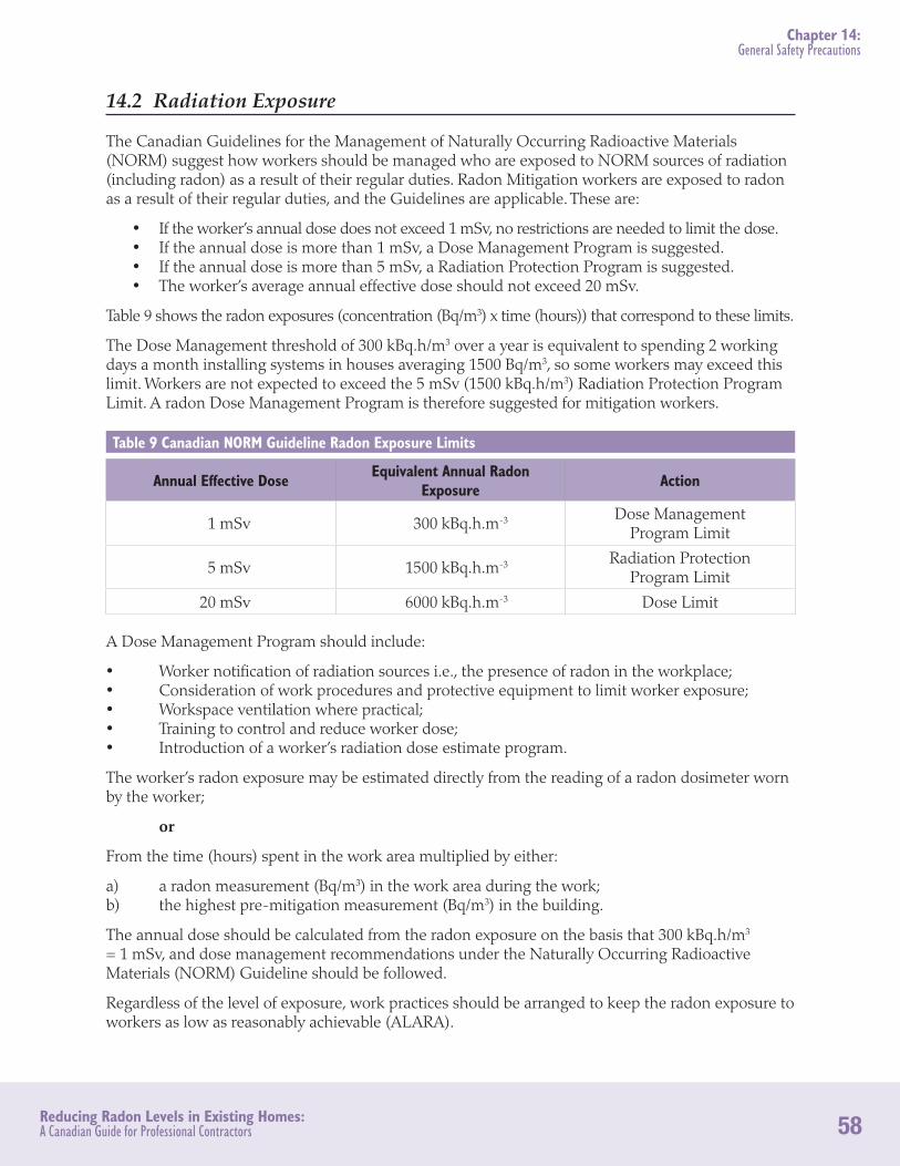
58Reducing Radon Levels in Existing Homes: A Canadian Guide for Professional Contractors
Chapter 14: General Safety Precautions
14.2 Radiation Exposure
The Canadian Guidelines for the Management of Naturally Occurring Radioactive Materials (NORM) suggest how workers should be managed who are exposed to NORM sources of radiation (including radon) as a result of their regular duties. Radon Mitigation workers are exposed to radon as a result of their regular duties, and the Guidelines are applicable. These are:
• If the worker’s annual dose does not exceed 1 mSv, no restrictions are needed to limit the dose. • If the annual dose is more than 1 mSv, a Dose Management Program is suggested. • If the annual dose is more than 5 mSv, a Radiation Protection Program is suggested. • The worker’s average annual effective dose should not exceed 20 mSv.
Table 9 shows the radon exposures (concentration (Bq/m3) x time (hours)) that correspond to these limits.
The Dose Management threshold of 300 kBq.h/m3 over a year is equivalent to spending 2 working days a month installing systems in houses averaging 1500 Bq/m3, so some workers may exceed this limit. Workers are not expected to exceed the 5 mSv (1500 kBq.h/m3) Radiation Protection Program Limit. A radon Dose Management Program is therefore suggested for mitigation workers.
Table 9 Canadian NORM Guideline Radon Exposure Limits
Annual Effective Dose Equivalent Annual Radon Exposure Action
1 mSv 300 kBq.h.m-3 Dose Management Program Limit
5 mSv 1500 kBq.h.m-3 Radiation Protection Program Limit
20 mSv 6000 kBq.h.m-3 Dose Limit
A Dose Management Program should include:
• Worker notification of radiation sources i.e., the presence of radon in the workplace;• Consideration of work procedures and protective equipment to limit worker exposure;• Workspace ventilation where practical;• Training to control and reduce worker dose;• Introduction of a worker’s radiation dose estimate program.
The worker’s radon exposure may be estimated directly from the reading of a radon dosimeter worn by the worker;
or
From the time (hours) spent in the work area multiplied by either:
a) a radon measurement (Bq/m3) in the work area during the work;b) the highest pre-mitigation measurement (Bq/m3) in the building.
The annual dose should be calculated from the radon exposure on the basis that 300 kBq.h/m3 = 1 mSv, and dose management recommendations under the Naturally Occurring Radioactive Materials (NORM) Guideline should be followed.
Regardless of the level of exposure, work practices should be arranged to keep the radon exposure to workers as low as reasonably achievable (ALARA).

59Reducing Radon Levels in Existing Homes: A Canadian Guide for Professional Contractors
ADDITIONAL REFERENCE MATERIAL
Additional Reference MaterialCanadian Guidelines for the Management of Naturally Occurring Radioactive Materials (NORM). (www.hc-sc.gc.ca/ewh-semt/alt_formats/hecs-sesc/pdf/pubs/contaminants/norm-mrn/00ehd245.pdf)
CMHC Research Highlight: Assessment of Natural Ventilation for Canadian Residential Buildings. Technical Series 08-100. (www.cmhc-schl.gc.ca/odpub/pdf/65903.pdf)
CMHC Research Highlight: Fixing Houses with High Radon - A Canadian Demonstration. Technical Series 08-105. (www.cmhc-schl.gc.ca/odpub/pdf/66063.pdf)
CMHC Research Highlight: Testing Oil-fired Appliance Depressurization Spillage. Technical Series 07-109. (www.cmhc-schl.gc.ca/odpub/pdf/65365.pdf)
CMHC Research Highlight: Laboratory depressurization test for residential gas appliances. Technical Series 05-111. (www.cmhc-schl.gc.ca/odpub/pdf/64806.pdf)
CMHC Research Highlight: Laboratory Depressurization Test for Residential Gas Appliances —Part 2. Technical Series 08-103. (www.cmhc-schl.gc.ca/odpub/pdf/65961.pdf)
Health Canada: Guide for Radon Measurements in Residential Dwellings (Homes). (www.hc-sc.gc.ca/ewh-semt/pubs/radiation/radon_homes-maisons/index-eng.php)
Heath Canada: RADON: IS IT IN YOUR HOME? [Online]. (www.hc-sc.gc.ca/ewh-semt/pubs/radiation/radon_brochure/index-eng.php)
Henschel D. B., Re-Entrainment and Dispersion of Exhausts from Indoor Radon Reduction Systems: Analysis of Tracer Gas Data. Indoor Air 1995, 5: 270 – 284.

60Reducing Radon Levels in Existing Homes: A Canadian Guide for Professional Contractors
GLOSSARY
Glossary Table 10 – Glossary of Terms
Air handler Part of the heating or cooling system that contains the air circulation blower.
Backdrafting Combustion products flow out of a natural draught stack into the house due to low house pressure.
Cavity Suction The suction required in the suction pit to produce the Design Suction at the slab edge.
Design Airflow The airflow from the suction pit required to produce the Design Suction.
Design Point The airflow and suction the fan must produce in the installed system.
Design Suction The suction needed in the fill at the slab edge to reduce the winter-time across-slab pressure difference to at least zero.
Dry Well A pit in the soil filled with coarse stone or gravel connected to a drain. It provides temporary water storage while the water drains away through the soil.
Dynamic Head (Vp) The pressure difference required to produce a given air velocity through a pipe or fitting.
Fire-rated wall A wall designed to resist a fire for a specified time.
Operating Point The airflow and suction the fan actually produces in the installed system.
Pitot tube A sensor tube to estimate air velocity from the pressure difference between two ports.
Radon fan In-line centrifugal fan designed for radon mitigation
Stack effect The difference in pressure between the top and bottom of an enclosure caused by the inside/outside temperature difference.
Suction pipe The part of a sub-slab exhaust system that is under suction.
Suction pit The cavity dug out from fill and soil beneath the floor slab. The sub-slab exhaust pipe draws air from this pit.
Suction point The actual location of the through-slab exhaust pipe.
Telepost An adjustable height metal post used to support the floor beams above.
Weeping tile A perforated drainpipe at footing level around the exterior perimeter of a house. Part of the ground water management system.
Window wells An excavation to allow light into below-grade windows.