radon solutions in homes
TRANSCRIPT

This Good Repair Guide offers guidance to builders and homeowners installing radon sump systems in homes. It covers the installation of both active (fan-assisted) and passive sump systems. Advice is also given on system maintenance and what to do if the system fails to adequately reduce radon levels.
This Good Repair Guide is Part 3 in a 3-Part set and replaces the guidance given in BRE Report BR 227. Part 1 covers underfloor ventilation and Part 2 covers positive house ventilation.
This guide is split into three sections: • introduction to radon and sump systems• guidance on installing sump systems, including
worksheets • maintaining systems and what to do if a sump
system does not reduce radon levels sufficiently.
BACKGROUNDRadonRadon is a naturally occurring radioactive gas that is present in all buildings. Prolonged exposure to high levels causes lung cancer. The Health Protection Agency (HPA) recommends that householders with concentrations above the action level (200 Bq m-3) should reduce their radon concentrations as far as they can and ideally to below the target level (100 Bq m-3).
Where can sump systems be used?These systems can be used on any building where:• there is a capping over the ground, such as a concrete
groundbearing slab• there is concrete capping to the soil beneath a
suspended timber floor• a standby sump was provided during construction (in
newer homes); see pages 2 and 6.
RADON SOLUTIONS IN HOMESRadon sump systems
Chris Scivyer
GOOD REPAIR GUIDE GRG 37 Part 3
Figure 1: Generic sump systems
Externally constructed sump with low-level exhaust
Internally constructed sump with high-level exhaust
Externally constructed sump with high-level exhaust
Externally constructed sump with low-level exhaust to a timber fl oor with concrete capping to the soil below

2 RADON SOLUTIONS IN HOMES: RADON SUMP SYSTEMS – GRG 37 PART 3
Internally constructed sumpFigure 4 provides detailed instructions for internally constructed sumps. The main benefit of internally constructed sumps is that the sump can be more centrally placed within the building. Unfortunately, this creates more disruption for the householder and it may be difficult to conveniently site the sump.
Prefabricated sumpsThe main benefit of prefabricated sumps is the ease of establishing a manifold of suction points. However, they will require more excavation and reinstatement of the floor afterwards (Figure 5).
Care should be taken when breaking out to avoid damaging steel reinforcement or concealed services such as electricity cables or water pipes.
Important tips• Avoid locating the sump near to an open-flued
appliance such as an open fire, gas fire or boiler that draws air from a room. It is very important that the sump does not draw flue gases into the room.
• To minimise noise the fan should be placed away from frequently occupied rooms, eg living rooms and bedrooms.
Newbuild properties (built since the early 1990s)It is important to check whether properties have been constructed with a standby sump (Figure 6). Properties with solid concrete floors, built since the early 1990s or so in areas of the country where radon risk is greatest, are likely to have been built with preventive measures.
Original drawings of the property may indicate the position of the sump. Alternatively, the presence of a sump would be indicated by a short length of 110 mm (4 inch) diameter pipe capped off close to the outside of the building. If a sump exists, it can be activated by adding a fan to the pipe.
Number of sumps requiredA single sump is generally sufficient for a typical dwelling. For most houses, a single sump and fan will have an influence over an area of 250 m2 (a radius of approximately 9 m around the sump). If the subsoil is particularly permeable a sump may be effective as much as 15 m from the sump. However, obstructions below the floor slab may reduce effectiveness.
Occasionally, larger or older houses may need more than one sump. An additional sump can be attached to the original fan by extending the pipework to include the second sump so that both sumps are powered by one fan. Alternatively, a second, separate sump system could be installed to target the specific problem area.
Sump systems are inappropriate for timber floors laid over bare earth unless additional work is carried out first to cap off the soil. In this case, refer to Parts 1 and 2 of this Good Repair Guide[1, 2].
What is a sump?A sump is simply an underfloor space or cavity into which a pipe is inserted and used to extract radon. The cavity prevents obstruction of the pipe with loose fill from the underfloor space.
How does a sump work?Radon gas does not drain into the sump but is drawn through the underfloor fill to the sump by the suction (pressure difference) created by an electric fan or the stack effect (warm air rising) and wind action on a passive sump pipe.
Active sump systemsAn open space of about the size of a bucket (volume approximately 10 L) is excavated beneath the ground floor, fitted with pipework and an electric fan. Active sump systems are the most effective at reducing indoor radon concentrations, particularly those with the highest radon concentrations.
Passive sumpsPassive sumps rely on the natural stack effect and wind action to extract radon from the ground, instead of using an electric fan. The absence of running costs makes the installation of passive sumps attractive, but they are much less effective in reducing radon than active sumps.
There are four generic positions for sumps and associated pipework (Figure 1).
Specifi cations for installing active sump systemsFigures 2–4 are technical worksheets for installing active sump systems, both with low- and high-level exhausts.
GUIDANCE ON INSTALLING SUMP SYSTEMSConstructionSumps can be constructed internally or externally.
Externally constructed mini sumpFigures 2 and 3 provide detailed instructions for externally constructed sumps. The main stages of sump construction are: 1. Break out or core drill a 120 mm (4½ inch) diameter
hole through the external wall just below the floor slab. 2. Excavate about a bucketful of material (volume
approximately 10 L) from under the floor slab. 3. Attach a pipe to link the sump to an electric fan in
order to exhaust radon outdoors.
A good seal must be made where the pipe runs through the wall (see Step 3 in Figures 2 and 3 and the ‘Sealing’ section on page 7).

3 RADON SOLUTIONS IN HOMES: RADON SUMP SYSTEMS – GRG 37 PART 3
2
4
8
3
9
1 5
7
2
8
4
9
1
7
5
6
3
6
Check that the ground fl oor construction is solid concrete or suspended timber with concrete capping to the soil below. For most houses a single sump and fan will have an infl uence over an area of 250 m2 (a radius of approximately 9 m around the sump). If the subsoil is particularly permeable a sump may be effective as much as 15 m from the sump. Find a location away from drains where there are no doors, windows or ventilation grilles.
1 Break out or core drill a 120 mm diameter hole through the external wall just below the fl oor slab.
2 Excavate about a bucketful of material (volume approximately 10 L) from under the fl oor slab to form a sump.
3 Install a short piece of 110 mm diameter pipe to tilt down 2.5° into the sump and seal it to the wall to minimise suction of air from within the wall or outdoors.
4 If the fan is to be mounted vertically (as in the lower diagram) then once the pipe has set in the wall attach an 87.5° short radius bend and short length of vertical pipe.
5 Attach an in-line centrifugal duct fan to the pipe from the sump using a rubber reducer coupling. (Typical fan fl ow rate 177 m3/h at a pressure difference of 200 Pa, 70 W power consumption.)
6 Support the fan from a bracket fi xed back to the building.
7 Wire the fan back to a fused spur inside the house.
8 If accessible, seal the joint between the fl oor and wall adjacent to the sump to minimise suction of air from the room.
9 Some fans require weather protection – a wooden box with a vent grille in front of the fan outlet can be used.
Figure 2: Worksheet for two examples of generic externally constructed mini sump systems with low-level exhausts

4 RADON SOLUTIONS IN HOMES: RADON SUMP SYSTEMS – GRG 37 PART 3
1
9
3
2
11
6
8
7
10
5
4
Check that the ground fl oor construction is solid concrete or suspended timber with concrete capping to the soil below. For most houses a single sump and fan will have an infl uence over an area of 250 m2 (a radius of approximately 9 m around the sump). If the subsoil is particularly permeable a sump may be effective as much as 15 m from the sump. Find a location away from drains where there are no doors, windows or ventilation grilles.
1 Break out or core drill a 120 mm diameter hole through the external wall just below the fl oor slab.
2 Excavate about a bucketful of material (volume approximately 10 L) from under the fl oor slab to form a sump.
3 Install a short piece of 110 mm diameter pipe to tilt down 2.5° into the sump and seal it to the wall to minimise suction of air from within the wall or outdoors.
4 Once the pipe has set in the wall attach an 87.5° short radius bend and short length of vertical pipe.
5 Attach an in-line centrifugal duct fan to the pipe from the sump using a rubber reducer coupling. (Typical fan fl ow rate 177 m3/h at a pressure difference of 200 Pa, 70 W power consumption.)
6 Support the fan from a bracket fi xed back to the building.
7 Install another rubber reducer coupling to the top of the fan with further pipework to just above the eaves level. The pipework can be cranked out around the fan and the eaves using bends in order to keep the pipework close to the wall.
8 Include a condensate drain just above the fan to prevent moisture running down the stack pipe and damaging the fan.
9 Wire the fan back to a fused spur inside the house.
10 Some fans require weather protection – a wooden box with a vent grille in front of the fan outlet can be used.
11 If accessible seal the joint between the fl oor and wall adjacent to the sump to minimise suction of air from the room.
Figure 3: Worksheet for generic externally constructed mini sump system with high-level exhaust
Detail for a suspended timber fl oor with oversite concrete

5 RADON SOLUTIONS IN HOMES: RADON SUMP SYSTEMS – GRG 37 PART 3
5
6
3
4
1
2
Check that the ground fl oor construction is solid concrete or suspended timber with concrete capping to the soil below. For most houses a single sump and fan will have an infl uence over an area of 250 m2 (a radius of approximately 9 m around the sump). If the subsoil is particularly permeable a sump may be effective as much as 15 m from the sump. Find a location away from drains, perhaps in the corner of a room or within a storey-height cupboard in a bungalow.
1 Break out or core drill a 120 mm diameter hole through the fl oor slab close to a wall, and excavate about a bucketful of material (volume approximately 10 L) from under the fl oor slab to form a sump.
2 Install a short piece of 110 mm diameter pipe into the sump to seal it to the concrete fl oor slab to minimise suction of air from the house into the sump.
3 Continue the pipe run into the roof space and attach an in-line centrifugal duct fan to the pipe from the sump using a rubber reducer coupling. (Typical fan fl ow rate 177 m3/h at a pressure difference of 200 Pa, 70 W power consumption.)
4 Support the fan from a bracket fi xed back to the building.
5 Install another rubber reducer coupling to the top of the fan with further pipework taken through the roof. The pipe needs to be sealed where it penetrates the roof covering and to terminate with a mushroom cowl approximately 600 mm above the roof.
6 Wire the fan back to a fused spur inside the house.
Figure 4: Worksheet for generic internally constructed mini sump system with high-level exhaust

6 RADON SOLUTIONS IN HOMES: RADON SUMP SYSTEMS – GRG 37 PART 3
Pipework requiredPVC-U pipe of 110 mm (4 inch) diameter and fittings that are used for domestic soil and vent pipes can be used. The fan connections are typically 150 mm in diameter, so a 150 mm to 110 mm reducer will be required to join the pipe to the fan.
Pipework must be thoroughly sealed where it exits the sump. For an internally constructed sump this means sealing around the pipe where it penetrates the floor slab. Pipework to an externally constructed mini sump must be sealed where it passes through the wall.
For cavity walls, the pipe must be well sealed where it passes through the inner leaf of the wall to prevent air being drawn from the cavity instead of the sump.
A condensate drain should be provided and located above the fan on an external vertical stack pipe (Figure 7).
FansIn-line or other duct-mounted centrifugal fans that have an airtight casing are most commonly used for radon sump systems (Figures 8 and 9). These are compact, quiet, widely available and easy to fit. There is no technical reason why other types of fan with similar air-flow performance should not be used. Fans should have a flow rate of around 175 m3/h and achieve a pressure difference of 200 Pa, and a power consumption of about 70 W. Lower wattage fans may be used where radon concentrations are only just above the recommended action level, to reduce the radon to below the target level.
Figure 5: Prefabricated sump installed internally awaiting reinstatement of concrete floor
Figure 6: Typical capped-off standby sump provided during house construction
Figure 7: Condensate drain fitted above a fan
Figure 8: Typical 150 mm centrifugal in-line duct fan
Figure 9: Another example of an in-line duct fan

7 RADON SOLUTIONS IN HOMES: RADON SUMP SYSTEMS – GRG 37 PART 3
Positive pressurisation of sumpsSo far this guide has described extraction sump systems where the fan sucks from the sump. These are generally successful and extraction mode is usually the first choice of most installers.
Occasionally, a fan extracting from a system does not reduce radon concentrations adequately. A simple remedy is to reverse the fan and blow air in, to pressurise the sump. It is important to measure radon concentrations again to ensure sufficient reduction.
Pressurisation of the sump tends to work effectively where the ground is naturally very permeable or where there has been past mining activity. Pressurisation using a fan dilutes the concentration of radon under the floor, whilst also achieving a sufficient pressure to counter the impact of the natural stack effect of the house that draws radon-laden air in. If it is known that the ground under the floor slab is very permeable it may be preferable to install a positive pressurisation sump system rather than an extraction system.
Sealing It is important to seal around the pipework where it exits the sump to ensure that all suction is applied beneath the building. This is particularly important with cavity walls to avoid extracting fresh air from the cavity rather than radon-laden air from under the building. This can be achieved using a gun-applied bathroom sealant or similar.
Exhaust outletsA high-level exhaust above the level of the eaves on the roof of the property is best for dissipating radon well away from the building (Figures 11 and 12).
High-level exhaust exits are often fitted with a cowl:• cowls are used to prevent rainwater reaching the fan• air flow out of the cowl can sometimes result in noise
nuisance. Cowls are generally required for systems where the exhaust outlet is immediately above a fan located in a roof space and is not protected by a condensate drain
• a cowl may not be required if a condensate drain (see ‘Pipework required’ section) is fitted above the fan to collect condensation from the stack pipe.
A low-level exhaust sump system can be used where the exhaust exit is sited appropriately so that there is no possibility of re-entry of exhaust gases into the building. Generally a low-level exhaust should be:• located at least 1.5 m or more from the nearest
opening into the house such as doors, windows, vents• located at least 1.5 m away from other buildings or
regularly used spaces such as patios • directed to discharge away from the building.
The majority of sump systems installed in the UK have a low-level exhaust because they are easier to install and are visually unobtrusive. Fans are often boxed in to disguise them (Figures 13–16).
Fans exposed to the weather should be suitably weather protected to level IP54 as classified in BS EN 60529:1992[3]. The fan manufacturer specification should confirm whether a fan complies with this requirement. Fans that do not meet this level of protection should be protected in a waterproof housing.
Fans should be wired in accordance with BS 7671:2008 as amended[4] and satisfy Approved Document P of the Building Regulations 2010 (England and Wales)[5]. The works required for sump systems are usually limited to providing an additional fused spur to an existing ring or radial circuit.
Important tips• Most sump fans are described as non-stalling.
However, some fan manufacturers recommend that a hole be drilled in the bottom of the fan casing or in the pipework between the fan and sump to prevent the fan from stalling due to a lack of air movement through impermeable soil. Check with the fan manufacturer as to their recommendations on sizing the hole. The hole should be no more than 5 mm diameter to avoid seriously compromising the suction created by the fan.
• It is important to locate an internal sump system fan close to the exhaust outlet to ensure all internal pipework is under suction This precaution limits the chance of radon-laden air entering the property in case of damage to the pipe.
• Fans and pipework located within occupied areas of a house can be boxed in to hide them (Figure 10).
• The fan must be switched on permanently, ie running day and night.
• If the installation work is in a kitchen, bathroom or shower room, the works will require notification to Building Control.
Figure 10: Fan and pipework boxed in within a garage

8 RADON SOLUTIONS IN HOMES: RADON SUMP SYSTEMS – GRG 37 PART 3
Figure 11: Externally constructed mini sump system with high-level exhaust
Figure 12: Externally constructed sump system with high-level exhaust
Figure 13: Modified meter cabinet housing a small centrifugal in-line sump fan, exhausting at low level
Figure 14: Centrifugal in-line radon sump fan in a box made of concrete paving slabs, exhausting at low level
Figure 15: Centrifugal in-line radon sump fan in a weatherproof wooden box, exhausting at low level
Figure 16: Sump fan located in an underground box, with just a vent cowl visible above the ground

9 RADON SOLUTIONS IN HOMES: RADON SUMP SYSTEMS – GRG 37 PART 3
The benefits are that several homeowners can share a system, reducing installation and running costs for individual homeowners. One downside of this approach is that homeowners will need a formal agreement that covers arrangements for paying for electricity, checking that the system is working and undertaking any maintenance required.
Suspended ground fl oors (over bare earth)It was stated earlier that sump systems cannot be used in properties with suspended floors over bare earth unless the ground below is capped first. Typically, the bare earth is capped with either concrete or a polyethylene sheet covered with concrete or gravel, laid over the sump and extract pipework. It is crucial that: • the polyethylene sheet is well sealed to the walls; this
is often difficult to carry out because of limited access• every separate underfloor space is capped; this can
prove particularly difficult with floors supported on sleeper walls.
The work involved in installing the capping is both disruptive and time consuming. Consequently, this approach is only used as a last resort.
Passive sump systemsSo far within this guide, the sump systems described have been fan assisted or ‘active’. This is because they are the most effective method for reducing radon in buildings.
Sumps without a fan are passive and are not as effective as those with a fan, but are suitable for radon concentrations that are slightly above the action level (around 200–300 Bq m-3) The main advantages are: • no running costs for passive sumps • silent running.
If the sump does not reduce radon levels sufficiently, a fan can be added later. Ensure that a space for a fan is allowed for at the planning stage.
How they workAn internal passive sump system uses the natural stack effect of the building (chimney or warm air rising effect within the pipe) together with the wind effect over the pipe exit to extract radon. These are the same effects that draw radon into the building. Stack effect is greater in winter because of the temperature difference between inside and outside, ie the house is heated and it is cold outside.
An external passive sump system relies upon the wind effect over the pipe exit and heat from the sun on the pipe to generate some stack effect in the pipe to extract radon. The effectiveness of passive stack systems can be enhanced by fitting a rotating chimney cowl to the pipe outlet.
After a sump system has been installed, a radon measurement should be made to ensure that the radon levels have been reduced sufficiently.
Noise reductionIn most cases sump systems run relatively quietly, but sometimes noise is a problem. Noise is often due to air movement and not the fan. To minimise noise, consider the following: • too many bends in pipework should be avoided –
keep the pipework as straight as possible• position the exhaust outlet away from doors or
windows – particularly bedroom windows, which may be left open at night
• insulation material could be placed around a fan that is mounted in a weathertight box
• ensure that internal fans are either supported on vibration mounts or connected within the pipe line on rubber couplings
• pipework should be supported by solid constructed walls, not lightweight partitions or dry-lined walls
• further advice is available in BRE Good Building Guide 26[6].
Communal sump systems A sump system can influence the reduction of radon in several homes, eg in blocks of flats or in homes joined together, semi-detached and terraced.
As previously mentioned, a sump system typically influences the reduction of radon in underfloor areas of approximately 250 m2. With a well-positioned sump at the junction between two semi-detached or terraced homes the sump system can reduce the radon concentration in more than one home.
In most party walls masonry joints below ground are rarely fully filled and are actually quite leaky. Consequently, communal or shared sump systems have been successfully used for reducing radon levels in several situations such as: • semi-detached and terraced houses• blocks of flats and apartments• separate houses with sumps manifolded to one fan
(Figure 17).
Figure 17: Communal sump system comprising a sump installed in each house and connected to a single fan and exhaust
10 RADON SOLUTIONS IN HOMES: RADON SUMP SYSTEMS – GRG 37 PART 3
radon measurement to ensure effectiveness. Shorter measurements (7–14 days) are not normally used and may lead to false indications because of the large ‘day-to-day’ fluctuations of radon concentrations.
The radon measurement should be repeated:• at intervals of 5–10 years • if there is a change of occupants• after changes to buildings such as adding an extension
or conservatory, installing new double-glazed windows or upgrading the insulation.
What to do if the sump system does not workTable 1 lists reasons why sump systems may not work and suggests further works to rectify the situation.
MAINTAINING SYSTEMSLong-term system inspection and maintenanceSystems should be checked to ensure that they continue to work effectively. A visual inspection of the system should be carried out annually.
Fans are ‘sealed for life’ so do not require lubrication. Check with manufacturers for fan life expectancy. BRE is aware of sump fans still working after 20 years’ continuous running.
Indications that the fan is workingAir movement should be detected around the exhaust from a low-level system, or the condensate drain in high-level systems. In addition, when standing close to the fan you should hear it running. One way to check is to listen with the fan switched on and again with it switched off. In most cases when a fan fails it stops and there is no noise. On the other hand a fan that is noisier than usual may suggest wear and tear and may need replacing.
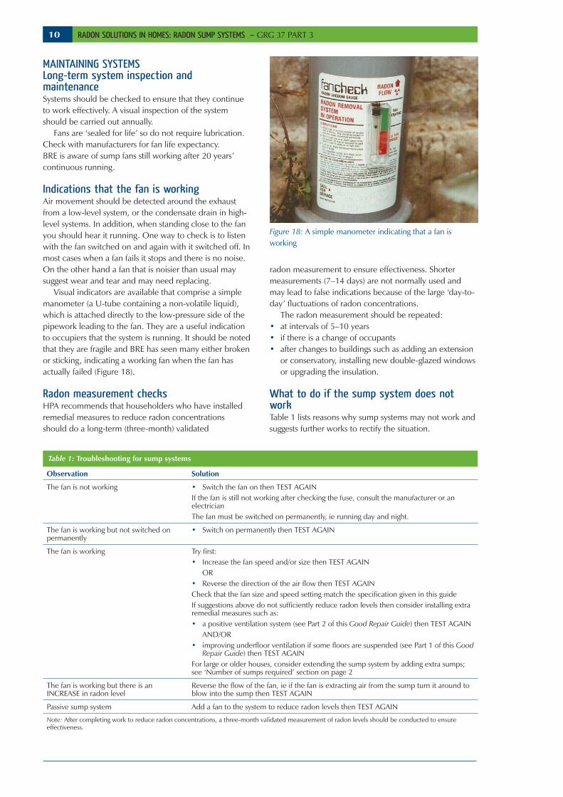
Visual indicators are available that comprise a simple manometer (a U-tube containing a non-volatile liquid), which is attached directly to the low-pressure side of the pipework leading to the fan. They are a useful indication to occupiers that the system is running. It should be noted that they are fragile and BRE has seen many either broken or sticking, indicating a working fan when the fan has actually failed (Figure 18).
Radon measurement checksHPA recommends that householders who have installed remedial measures to reduce radon concentrations should do a long-term (three-month) validated
Figure 18: A simple manometer indicating that a fan is working
Observation Solution
The fan is not working • Switch the fan on then TEST AGAINIf the fan is still not working after checking the fuse, consult the manufacturer or an electricianThe fan must be switched on permanently, ie running day and night.
The fan is working but not switched on permanently
• Switch on permanently then TEST AGAIN
The fan is working Try first:• Increase the fan speed and/or size then TEST AGAIN
OR• Reverse the direction of the air flow then TEST AGAINCheck that the fan size and speed setting match the specification given in this guideIf suggestions above do not sufficiently reduce radon levels then consider installing extra remedial measures such as:• a positive ventilation system (see Part 2 of this Good Repair Guide) then TEST AGAIN
AND/OR• improving underfloor ventilation if some floors are suspended (see Part 1 of this Good
Repair Guide) then TEST AGAINFor large or older houses, consider extending the sump system by adding extra sumps; see ‘Number of sumps required’ section on page 2
The fan is working but there is an INCREASE in radon level
Reverse the flow of the fan, ie if the fan is extracting air from the sump turn it around to blow into the sump then TEST AGAIN
Passive sump system Add a fan to the system to reduce radon levels then TEST AGAIN
Note: After completing work to reduce radon concentrations, a three-month validated measurement of radon levels should be conducted to ensure effectiveness.
Table 1: Troubleshooting for sump systems
11 RADON SOLUTIONS IN HOMES: RADON SUMP SYSTEMS – GRG 37 PART 3
FURTHER INFORMATIONAdvice on radon risk and testing is available from the Health Protection Agency, Chilton, Didcot, Oxfordshire OX11 ORQ. Tel: 01235 822622. www.ukradon.org.
REFERENCES[1] Scivyer C. Radon solutions in homes: improving underfloor ventilation. BRE GR 37/1. Bracknell, IHS BRE Press, 2012.[2] Scivyer C. Radon solutions in homes: positive ventilation systems. BRE GR 37/2. Bracknell, IHS BRE Press, 2013.[3] BSI. Specification for degrees of protection provided by enclosures (IP code). BS EN 60529:1992. London, BSI, 1992.[4] BSI. Requirements for electrical installations: IET wiring regulations. BS 7671:2008 incorporating Amendment No. 1:2011. Stevenage, Institution of Engineering and Technology (IET), 2011.[5] Department for Communities and Local Government (DCLG). The Building Regulations 2010. Approved Document P: Electrical safety: dwellings (2006 edn incorporating 2010 amendments). London, DCLG, 2010.[6] BRE. Minimising noise from domestic fan systems and fan-assisted radon mitigation systems. BRE GG 26. Bracknell, IHS BRE Press, 1996.
Diagnostics for specialistsA manometer can be used to measure the pressure difference between the sump and the room above or between outdoors and inside the extract pipe to diagnose problems. • Most successful sumps operate with a pressure
difference of 50–200 Pa or more.• If the pressure is less than about 20 Pa, this might
indicate short circuiting of air into the sump due to a poor seal around the extract pipe where it exits the floor or through the wall. It could also indicate permeable ground.
• If the pressure difference exceeds 200 Pa, this could be an indication that there is little air moving through the system, suggesting that the soil beneath the building is highly impermeable.
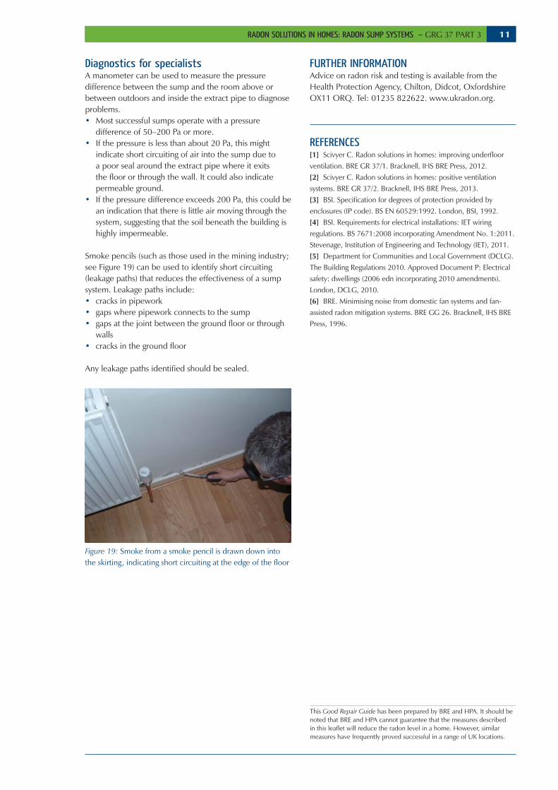
Smoke pencils (such as those used in the mining industry; see Figure 19) can be used to identify short circuiting (leakage paths) that reduces the effectiveness of a sump system. Leakage paths include: • cracks in pipework• gaps where pipework connects to the sump• gaps at the joint between the ground floor or through
walls • cracks in the ground floor
Any leakage paths identified should be sealed.
Figure 19: Smoke from a smoke pencil is drawn down into the skirting, indicating short circuiting at the edge of the floor
This Good Repair Guide has been prepared by BRE and HPA. It should be noted that BRE and HPA cannot guarantee that the measures described in this leaflet will reduce the radon level in a home. However, similar measures have frequently proved successful in a range of UK locations.

12
BRE is the UK’s leading centre of expertise on the built environment, construction, energy use in buildings, fire prevention and control, and risk management. BRE is a part of the BRE Group, a world leading research, consultancy, training, testing and certification organisation, delivering sustainability and innovation across the built environment and beyond. The BRE Group is wholly owned by the BRE Trust, a registered charity aiming to advance knowledge, innovation and communication in all matters concerning the built environment for the benefit of all. All BRE Group profits are passed to the BRE Trust to promote its charitable objectives.BRE is committed to providing impartial and authoritative information on all aspects of the built environment. We make every effort to ensure the accuracy and quality of information and guidance when it is published. However, we can take no responsibility for the subsequent use of this information, nor for any errors or omissions it may contain.BRE, Garston, Watford WD25 9XXTel: 01923 664000, Email: [email protected], www.bre.co.uk
Good Repair Guides are accessible guides to the defects most commonly encountered in buildings and offer sound advice on putting them right. They are highly illustrated to make the problems and solutions easy to identify and understand. Digests, Information Papers, Good Building Guides and Good Repair Guides are available on subscription in hard copy and online through BRE Connect. For more details call 01344 328038. BRE publications are available from www.brebookshop.com, orIHS BRE Press, Willoughby Road, Bracknell RG12 8FBTel: 01344 328038, Fax: 01344 328005, Email: [email protected] to copy any part of this publication should be made to:IHS BRE Press, Garston, Watford WD25 9XXTel: 01923 664761 Email: [email protected] www.brebookshop.com
GR 37, Part 3© BRE 2013
February 2013ISBN 978-1-84806-302-0 (Part 3)
ISBN 978-1-84806-303-7 (3-Part set)
RADON SOLUTIONS IN HOMES: RADON SUMP SYSTEMS – GRG 37 PART 3
The preparation and publication of this Good Repair Guide was funded by BRE Trust and the Health Protection Agency.
The author would like to acknowledge the assistance of Airtech Environmental Systems, JR Board, Stephen Hunter, Radon Centres Ltd and Glencoe Radon Gas Centres for supplying photographs for this guide.
Acknowledgements
Other radon publications from BRERadon protection for new domestic extensions and conservatories with solid concrete ground floorsGood Building Guide 73
Get practical guidance on providing radon protection to new domestic extensions and conservatories and understand why it is necessary. This Good Building Guide will also help house owners and builders in radon-affected areas to determine whether protection is needed and the level of protection that is required.
Radon protection for new dwellingsAvoiding problems and getting it right!Good Building Guide 74
Find out how to install radon-protectiion measures in new dwellings successfully. This Good Building Guide will help designers, site managers, building control authorities and site operatives to ensure that radon-protection measures work.
Radon protection for new large buildingsGood Building Guide 75
Find out how to install radon-protection measures within large buildings successfully, eg laying a radon-proof barrier across a large floor area, how many sumps to install and how to construct the sump and pipework. In addition to the requirements of building regulations, a building used as a workplace has to meet the requirements of the Ionising Radiations Regulations 1999.
Radon: Guidance on protective measures for new buildingsBRE Report BR 211, 2007 edition
Get practical guidance for reducing the concentration of radon in new buildings, extensions, conversions and refurbishment projects. This guide will help architects, designers, builders and installers to specify and install successful protective measures to reduce the risk of exposure to radon. The guide contains updated maps of England and Wales for identifying areas where radon protective measures should be installed.
All titles are available in print and pdf format. Good Building Guides 73–75 are available individually or as a set of three.
Order now @ www.brebookshop.com or phone the IHS Sales Team on +44 (0) 1344 328038.