reading and writing rfid data with simatic s7-1200 … · applications & tools answers for...
TRANSCRIPT

Applications & Tools
Answers for industry.
Cover
Reading and Writing RFID Data with SIMATIC S7-1200 and SIMATIC RF160C via PROFIBUS DP SIMATIC RF160C, STEP 7 V11
Application Description December 2012

2 Reading from and Writing to Transponders with an S7-1200 CPU and RF160C
V1.0, Entry ID: 63969277
Cop
yrig
ht
Sie
men
s A
G 2
012
All
right
s re
serv
ed
Siemens Industry Online Support This entry is taken from Siemens Industry Online Support. The following link takes you directly to the download page of this document: http://support.automation.siemens.com/WW/view/en/63929277 Caution The functions and solutions described in this entry predominantly confine themselves to the realization of the automation task. Please also take into account that corresponding protective measures have to be taken in the context of Industrial Security when connecting your equipment to other parts of the plant, the enterprise network or the Internet. For more information, please refer to Entry ID 50203404. http://support.automation.siemens.com/WW/view/en/50203404 Please also actively use our Technical Forum in Siemens Industry Online Support regarding this subject. Share your questions, suggestions or problems and discuss them with our strong forum community: http://www.siemens.com/forum-applications

Reading from and Writing to Transponders with an S7-1200 CPU and RF160C V1.0, Entry ID: 63969277 3
Cop
yrig
ht
Sie
men
s A
G 2
012
All
right
s re
serv
ed
s
SIMATIC Reading from and Writing to Transponders with an S7-1200 CPU and RF160C Application Description
Task 1
Solution 2
Function Mechanisms of this Application
3 Installation and Commissioning
4 Operation of the Application
5
References 6
History 7

Warranty and Liability
4 Reading from and Writing to Transponders with an S7-1200 CPU and RF160C
V1.0, Entry ID: 63969277
Cop
yrig
ht
Sie
men
s A
G 2
012
All
right
s re
serv
ed
Warranty and Liability
Note The Application Examples are not binding and do not claim to be complete regarding the circuits shown, equipping and any eventuality. The Application Examples do not represent customer-specific solutions. They are only intended to provide support for typical applications. You are responsible for ensuring that the described products are used correctly. These Application Examples do not relieve you of the responsibility to use safe practices in application, installation, operation and maintenance. When using these Application Examples, you recognize that we cannot be made liable for any damage/claims beyond the liability clause described. We reserve the right to make changes to these Application Examples at any time without prior notice. If there are any deviations between the recommendations provided in these Application Examples and other Siemens publications – e.g. Catalogs – the contents of the other documents have priority.
We do not accept any liability for the information contained in this document.
Any claims against us – based on whatever legal reason – resulting from the use of the examples, information, programs, engineering and performance data etc., described in this Application Example shall be excluded. Such an exclusion shall not apply in the case of mandatory liability, e.g. under the German Product Liability Act (“Produkthaftungsgesetz”), in case of intent, gross negligence, or injury of life, body or health, guarantee for the quality of a product, fraudulent concealment of a deficiency or breach of a condition which goes to the root of the contract (“wesentliche Vertragspflichten”). The damages for a breach of a substantial contractual obligation are, however, limited to the foreseeable damage, typical for the type of contract, except in the event of intent or gross negligence or injury to life, body or health. The above provisions do not imply a change of the burden of proof to your detriment. Any form of duplication or distribution of these Application Examples or excerpts hereof is prohibited without the expressed consent of Siemens Industry Sector.

Table of Contents
Reading from and Writing to Transponders with an S7-1200 CPU and RF160C V1.0, Entry ID: 63969277 5
Cop
yrig
ht
Sie
men
s A
G 2
012
All
right
s re
serv
ed
Table of Contents Warranty and Liability..............................................................................................4 1 Task.................................................................................................................6 2 Solution...........................................................................................................8
2.1 Overview...........................................................................................8 2.2 Description of the core functionality....................................................9 2.3 Hardware and software components used .......................................12 2.4 Performance data............................................................................13
3 Function Mechanisms of this Application...................................................14 3.1 Functionality of the application example...........................................14 3.1.1 Reset the RF160C communication module ......................................14 3.1.2 Read RFID data from transponder ...................................................15 3.1.3 Write RFID data to transponder .......................................................16 3.2 Description of the STEP 7 V11 project .............................................17 3.2.1 Overview.........................................................................................17 3.2.2 Startup program (OB100) ................................................................17 3.2.3 Standard user program (OB1)..........................................................18 3.2.4 FB RF160C_RW parameters ...........................................................19 3.2.5 Call example: FB RF160C_RW (FB160) in OB1...............................20 3.2.6 Global data block: RF_PARAMETER (DB1).....................................21 3.2.7 Configuration and project engineering of the SIMATIC Panel ...........22 3.3 Error and status display ...................................................................25 3.3.1 Error messages of the FB RF160C_RW (FB160) function block
and the function blocks of the library ................................................25 3.3.2 Error messages of the RF160C or connected readers......................25
4 Installation and Commissioning..................................................................26 4.1 Hardware configuration....................................................................26 4.1.1 Hardware configuration of the S7 station..........................................27 4.1.2 Hardware configuration of the RF160C communication module .......27 4.2 Installation of the standard software.................................................27 4.3 Installation of the STEP 7 V11 project ..............................................28 4.4 Configuration of the PG/PC..............................................................28 4.5 Configuration of the S7 station.........................................................29 4.6 Parameterization of the RF160C communication module .................31 4.7 Downloading the STEP 7 V11 project to the S7 CPU.......................33
5 Operation of the Application........................................................................34 5.1 Starting the HMI simulation..............................................................34 5.2 Watch table .....................................................................................35 5.3 Resetting the RF160C communication module.................................36 5.4 Reading RFID data from the transponder.........................................37 5.5 Writing RFID data to the transponder ...............................................38 5.6 Error while reading RFID data..........................................................39
6 References....................................................................................................41 6.1 Bibliography.....................................................................................41 6.2 Internet links....................................................................................41
7 History ..........................................................................................................41

1 Task
6 Reading from and Writing to Transponders with an S7-1200 CPU and RF160C
V1.0, Entry ID: 63969277
Cop
yrig
ht
Sie
men
s A
G 2
012
All
right
s re
serv
ed
1 Task Introduction
For incoming goods, stock keeping, production logistics and distribution, RFID (Radio Frequency Identification) provides complete tracking and documentation of all received, stored and shipped goods. For this purpose, a small data medium – referred to as a transponder – that stores all essential information is attached to each product, package or pallet. A read/write device is used to read from and write to the transponder. The figure below shows an example of such a situation. Figure 1-1
Overview of the automation task To ensure complete tracking and documentation or to benefit from the use of RFID technology even during production, the connection to automation systems via communication modules and convenient function blocks is required in many cases. Figure 1-2 Automation station
RFID
REA
DER
S7-1
200
stat
ion
Automation station
ID:1 ID:2
Com
mun
icat
ion
mod
ule
Function blocks in the automation
system

1 Task
Reading from and Writing to Transponders with an S7-1200 CPU and RF160C V1.0, Entry ID: 63969277 7
Cop
yrig
ht
Sie
men
s A
G 2
012
All
right
s re
serv
ed
Requirements The aim of this application is to cover the following requirements: An RF160C communication module is to be used to connect an RF300 reader
to an S7-1200 CPU via PROFIBUS DP. The intention is to show how easily the function blocks of the
RF160C_S71200_V11_Library library can be used for this task. The following RFID functions are to be implemented in the user program:
– Reset RF160C communication module (RF160C_RESET) – Read RFID data from transponders (RF160C_READ) – Write RFID data to transponder (RF160C_WRITE) – Turn integrated antenna of RF310R reader on/off (RF160C_ANT_300)
Integration of simple functions to monitor the implemented processes Error handling Operating option via a panel
A SIMATIC RF310R reader with a SIMATIC S7-1214C CPU is to be used to implement the application.
2 Solution 2.1 Overview
8 Reading from and Writing to Transponders with an S7-1200 CPU and RF160C
V1.0, Entry ID: 63969277
Cop
yrig
ht
Sie
men
s A
G 2
012
All
right
s re
serv
ed
2 Solution 2.1 Overview
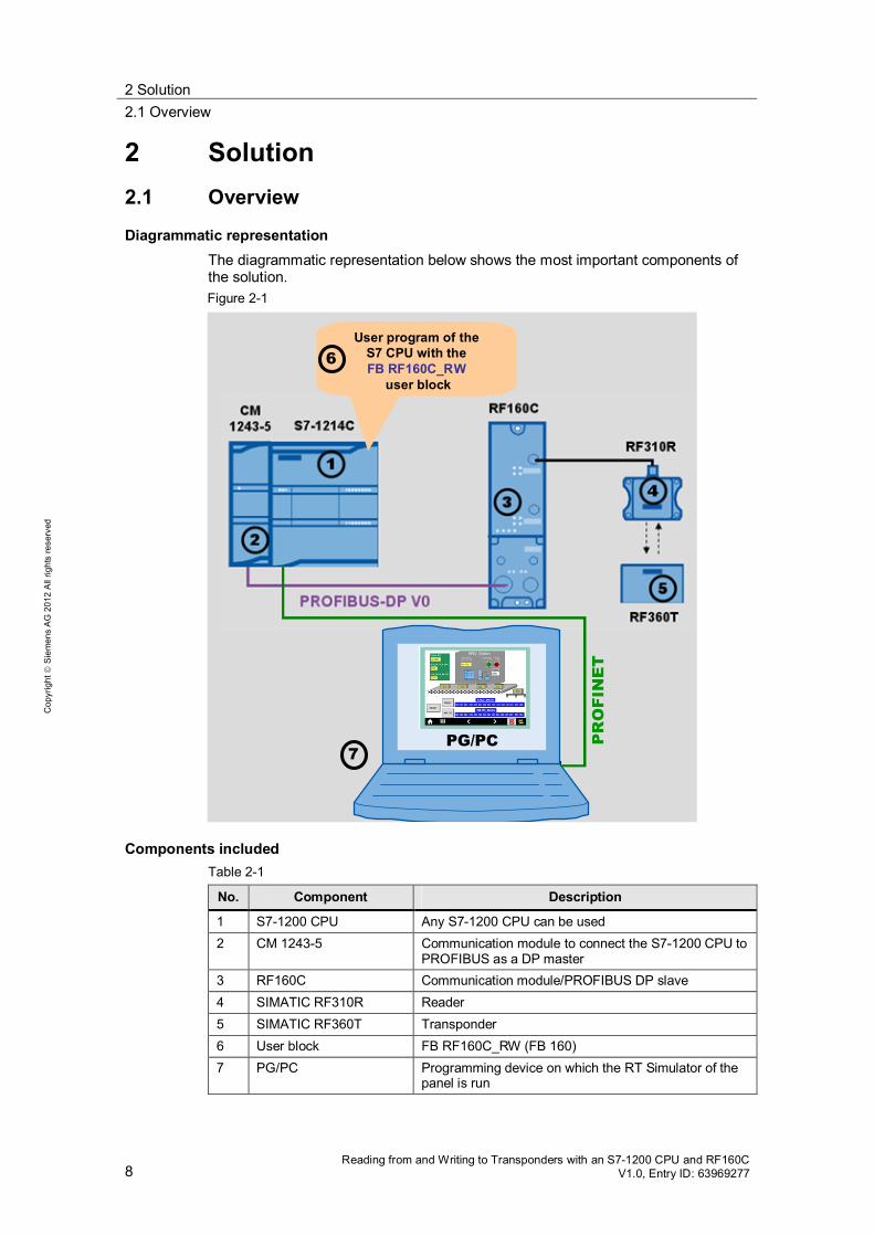
Diagrammatic representation The diagrammatic representation below shows the most important components of the solution. Figure 2-1
User program of theS7 CPU with theFB RF160C_RW
user block
6
PG/PC7
PR
OFI
NE
T
Components included Table 2-1
No. Component Description
1 S7-1200 CPU Any S7-1200 CPU can be used 2 CM 1243-5 Communication module to connect the S7-1200 CPU to
PROFIBUS as a DP master 3 RF160C Communication module/PROFIBUS DP slave 4 SIMATIC RF310R Reader 5 SIMATIC RF360T Transponder 6 User block FB RF160C_RW (FB 160) 7 PG/PC Programming device on which the RT Simulator of the
panel is run

2 Solution 2.2 Description of the core functionality
Reading from and Writing to Transponders with an S7-1200 CPU and RF160C V1.0, Entry ID: 63969277 9
Cop
yrig
ht
Sie
men
s A
G 2
012
All
right
s re
serv
ed
Configuration The RF310R is connected to the S7-1200 via PROFIBUS DP using the RF160C communication module to which the RF310R is connected via its RS422 interface. The FB RF160C_RW (FB160) user block has been created with the function blocks from the RF160C_S71200_V11_Library library. The interconnection of the RFID functions, monitoring functions and error handling are implemented in this block.
2.2 Description of the core functionality
Functions implemented The following functions are implemented in the application example: Reset the RF160C communication module during startup of the S7-12001. Turn on the integrated antenna of the RF310R reader before starting a read or
write job. Read RFID data when a transponder is in the reader’s field. Write RFID data when a transponder is in the reader’s field. Turn off the integrated antenna of the RF310R reader when a job has
completed successfully or with an error. Time monitoring of the read, write function.
Note For a more detailed description of these functions, please refer to chapter 3 and the following chapters.
Explanations of the difference between job and function Read job: Call of the RF160C_READ function block of the library Write job: Call of the RF160C_WRITE function block of the library Reset job Call of the RF160C_RESET function block of the library Read function: The entire process for reading RFID data, including turning the integrated antenna of the reader on and off, read job and monitoring function. Write function: The entire process for writing RFID data, including turning the integrated antenna of the reader on and off, write job and monitoring function. Reset function: The entire process for resetting the RF160C communication module, including RESET job and turning off the integrated antenna of the reader.
1 This function is also used to reset a read or write job or for error recovery.

2 Solution 2.2 Description of the core functionality
10 Reading from and Writing to Transponders with an S7-1200 CPU and RF160C
V1.0, Entry ID: 63969277
Cop
yrig
ht
Sie
men
s A
G 2
012
All
right
s re
serv
ed
Description of the user interface on the SIMATIC Panel The application is operated using a configured SIMATIC KTP 1000 TouchPanel run in simulation mode directly on the programming device. The following figure and table describe the tags of the user interface. Alternatively, you can monitor or modify these tags using a watch table in STEP 7. Figure 2-2 User interface of the panel used
1
2
3
4 5
7
89
10
11
6
12
Table 2-2
No. Element Description
1 Timer IN Input field: This timer monitors whether a transponder is in the reader’s field. Period: Preset to 10 s.
2 LEN_DATA_R Input field: Length of the RFID data that is read from the transponder (1..1000 bytes).
3 LEN_DATA_W Input field: Length of the RFID data that is written to the transponder (1..1000 bytes).
4 Timer (s) Output field: Elapsed time of the timer in seconds.
5 Presence Presence bit On: Transponder in the reader’s field Off: No transponder in the reader’s field

2 Solution 2.2 Description of the core functionality
Reading from and Writing to Transponders with an S7-1200 CPU and RF160C V1.0, Entry ID: 63969277 11
Cop
yrig
ht
Sie
men
s A
G 2
012
All
right
s re
serv
ed
No. Element Description
6 Error Error bit On: Error Off: No error
7 Status Output field: Status display (see chapter 3.3)
8 RESET Button: Enables reset of the RF160C communication module.
9 READ Button: Enables the read function.
10 WRITE Button: Enables the write function.
11 READ_DATA Output fields: Display of the data read from the transponder (max. 15 bytes).
12 WRITE_DATA Input fields: Input of data to be written to the transponder (max. 15 bytes).
Scope This application does not include the basics of SIMATIC RF160C. For more information, refer to document \3\. SIMATIC RF310R. For more information, refer to document \4\. the LAD/ FBD/ STL/ SCL programming languages. SIMATIC HMI HMI devices Basic Panels \5\.
Basic knowledge of these topics is required.
Validity of the application All S7-1200 CPUs from the SIMATIC product range STEP 7 V11, SP2 WINCC V11, SP2 Readers of the RFID families RF200/300/600, MOBY D/U (RS422 interface)
Advantages of this solution This application example already includes the above-described functions on a fully implemented basis can be easily customized for extensions already includes the parameterization of the RF160C communication module can be commissioned quickly.

2 Solution 2.3 Hardware and software components used
12 Reading from and Writing to Transponders with an S7-1200 CPU and RF160C
V1.0, Entry ID: 63969277
Cop
yrig
ht
Sie
men
s A
G 2
012
All
right
s re
serv
ed
Typical main areas of application The RF160C communication module has been specifically designed for a wide range of applications in industrial automation and logistics. Main areas of application for the RF160C and this application: Machine building industry, automation systems, conveyor systems Auxiliary assembly lines in the automotive industry/suppliers Small assembly lines
2.3 Hardware and software components used
The application was created with the following components:
Hardware components Table 2-3
Component Qty. Order no. Note
PM1207 power supply
1 6EP1332-1SH71
CPU 1214C DC/DC/DC
1 6ES7214-1AE30-0XB0 Alternatively, another S7-1200 CPU from the SIMATIC product range can also be used.
CM 1243-5 communication module
1 6GK7 243-5DX30-0XE0
RF160C 1 6GT2002-0EF00 ECOFAST connection block
1 6ES7194-3AA00-0AA0
M12 connection block, 7/8"
1 6ES7194-3AA00-0BA0
RF310R 1 6GT2801-1AB10 Alternatively, another reader with RS422 interface can also be used.
RF360T n 6GT2800-4AC00 Alternatively, another transponder can also be used.
M12 cable plug 1 6GT2891-0LH50 (5 m) or 6GT2891-0LN10 (10 m)
Standard software components Table 2-4
Component Qty. Order no.
STEP 7 Professional V11, SP2 1 6ES7822-1AA01-0YA5 WinCC Professional V11, SP2 1 6AV2103-0DA01-0AA5

2 Solution 2.4 Performance data
Reading from and Writing to Transponders with an S7-1200 CPU and RF160C V1.0, Entry ID: 63969277 13
Cop
yrig
ht
Sie
men
s A
G 2
012
All
right
s re
serv
ed
Sample files and projects The following list contains all files and projects that are used in this example. Table 2-5
Component Note
63969277_RF160C_RW_CODE_V1_0.zip This zip file contains the STEP 7 project.
63969277_RF160C_RW_DOKU_V1_0_de.pdf This document.
2.4 Performance data
The following section gives you an overview of the size of the blocks of the STEP 7 project in the S7 CPU’s main memory.
Blocks used and resource requirements The size of all blocks in the S7 CPU’s main memory is 19264 bytes. They are composed as follows. Figure 2-3
Libraryelements
3 Function Mechanisms of this Application 3.1 Functionality of the application example
14 Reading from and Writing to Transponders with an S7-1200 CPU and RF160C
V1.0, Entry ID: 63969277
Cop
yrig
ht
Sie
men
s A
G 2
012
All
right
s re
serv
ed
3 Function Mechanisms of this Application 3.1 Functionality of the application example
3.1.1 Reset the RF160C communication module
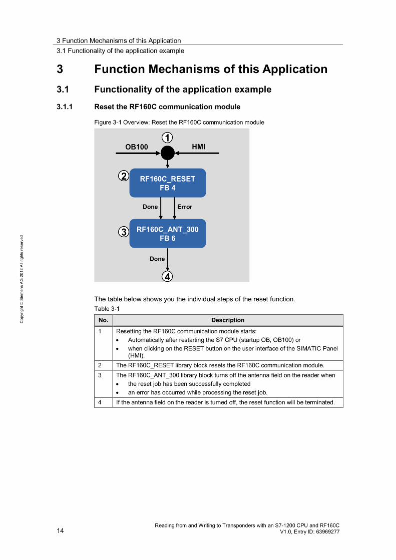
Figure 3-1 Overview: Reset the RF160C communication module
1
2
Done
RF160C_RESETFB 4
HMI
RF160C_ANT_300FB 6
3
4
Done Error
OB100
The table below shows you the individual steps of the reset function. Table 3-1
No. Description
1 Resetting the RF160C communication module starts: Automatically after restarting the S7 CPU (startup OB, OB100) or when clicking on the RESET button on the user interface of the SIMATIC Panel
(HMI). 2 The RF160C_RESET library block resets the RF160C communication module. 3 The RF160C_ANT_300 library block turns off the antenna field on the reader when
the reset job has been successfully completed an error has occurred while processing the reset job.
4 If the antenna field on the reader is turned off, the reset function will be terminated.

3 Function Mechanisms of this Application 3.1 Functionality of the application example
Reading from and Writing to Transponders with an S7-1200 CPU and RF160C V1.0, Entry ID: 63969277 15
Cop
yrig
ht
Sie
men
s A
G 2
012
All
right
s re
serv
ed
3.1.2 Read RFID data from transponder
Figure 3-2 Overview: Read RFID data from transponder
1
2
Done
Transponderdetected
RF160C_ANT_300FB 6
HMI
TONR10s
RF160C_READFB 2
3
4
Done Error
5
Notransponder
detected
RF160C_ANT_300FB 6
The table below shows you the individual steps of the read function (Read RFID data from transponder). Table 3-2
No. Description
1 Use the READ button on the user interface of the SIMATIC Panel (HMI) to start the read function.
2 The RF160C_ANT_300 library block turns on the antenna field on the reader. 3 The TONR watchdog timer monitors whether a transponder is in the reader’s field. It
is preset to 10 s. 4 If a transponder is detected in the reader’s field within 10 s, the RF160C_READ
library block will read the RFID data from the transponder. 5 The RF160C_ANT_300 library block turns off the antenna field on the reader when
the read job has been successfully completed an error has occurred while processing the read job no transponder was detected in the reader’s field within 10 s.
Turning off the antenna field terminates the read function.

3 Function Mechanisms of this Application 3.1 Functionality of the application example
16 Reading from and Writing to Transponders with an S7-1200 CPU and RF160C
V1.0, Entry ID: 63969277
Cop
yrig
ht
Sie
men
s A
G 2
012
All
right
s re
serv
ed
3.1.3 Write RFID data to transponder
Figure 3-3 Overview: Write RFID data to transponder
1
2
Done
Transponderdetected
RF160C_ANT_300FB 6
HMI
TONR10s
RF160C_WRITEFB 3
3
4
Done Error
5
Notransponder
detected
RF160C_ANT_300FB 6
The table below shows you the individual steps of the write function (Write RFID data to transponder). Table 3-3
No. Description
1 Use the WRITE button on the user interface of the SIMATIC Panel (HMI) to start the write function.
2 The RF160C_ANT_300 library block turns on the antenna field on the reader. 3 A TONR watchdog timer monitors whether a transponder is in the reader’s field. It is
preset to 10 s. 4 If a transponder is detected in the reader’s field within 10 s, the RF160C_WRITE
library block will write the RFID data to the transponder. 5 The RF160C_ANT_300 library block turns off the antenna field on the reader when
the write job has been successfully completed an error has occurred while processing the write job no transponder was detected in the reader’s field within 10 s.
Turning off the antenna field terminates the write function.

3 Function Mechanisms of this Application 3.2 Description of the STEP 7 V11 project
Reading from and Writing to Transponders with an S7-1200 CPU and RF160C V1.0, Entry ID: 63969277 17
Cop
yrig
ht
Sie
men
s A
G 2
012
All
right
s re
serv
ed
3.2 Description of the STEP 7 V11 project
3.2.1 Overview
Introduction The STEP 7 V11 project contains the user program for the S7 CPU:
– Startup program (OB100) – Standard user program (OB1)
Configuration and project engineering of the SIMATIC Panel.
Diagrammatic representation The figure below shows the program structure of the entire STEP 7 project. Figure 3-4
RF160C_RW
FB160
Userblocks
OB1RF160C_READ
FB2
RF160C_WRITE
FB3
Libraryblocks
TONR monitoringCALL
HMIDB
RF_PARAMETER
CALL
Systemfunctions
OB100Start_up
RF160C_ANT_300
FB6
RF160C_RESET
FB1
functionRF160C_READ
FB2
RF160C_WRITE
FB3
RF160C_ANT_300
FB6
RF160C_RESET
FB4
3.2.2 Startup program (OB100)
After startup of the RF160C, it must be reset. Reset is performed automatically after restarting the S7 CPU. In the startup OB, OB100, the RF_PARAMETER.Start_up variable is set to the value 1. Therefore, the RF160C_RESET block is called with input EXECUTE = Start_up when called for the first time in OB1. Then the RF_PARAMETER.Start_up variable is reset to the value 0 in OB1.
3 Function Mechanisms of this Application 3.2 Description of the STEP 7 V11 project
18 Reading from and Writing to Transponders with an S7-1200 CPU and RF160C
V1.0, Entry ID: 63969277
Cop
yrig
ht
Sie
men
s A
G 2
012
All
right
s re
serv
ed
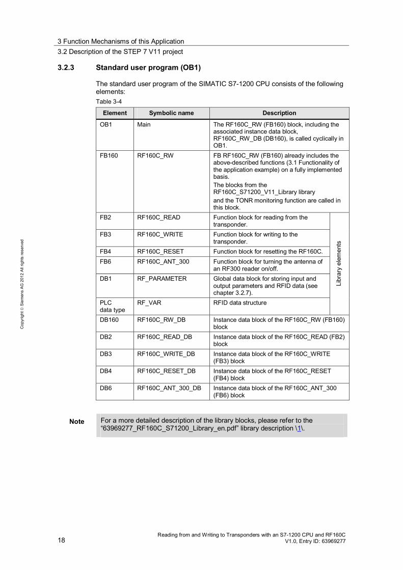
3.2.3 Standard user program (OB1)
The standard user program of the SIMATIC S7-1200 CPU consists of the following elements: Table 3-4
Element Symbolic name Description
OB1 Main The RF160C_RW (FB160) block, including the associated instance data block, RF160C_RW_DB (DB160), is called cyclically in OB1.
FB160 RF160C_RW FB RF160C_RW (FB160) already includes the above-described functions (3.1 Functionality of the application example) on a fully implemented basis. The blocks from the RF160C_S71200_V11_Library library and the TONR monitoring function are called in this block.
FB2 RF160C_READ Function block for reading from the transponder.
FB3 RF160C_WRITE Function block for writing to the transponder.
FB4 RF160C_RESET Function block for resetting the RF160C. FB6 RF160C_ANT_300 Function block for turning the antenna of
an RF300 reader on/off. DB1 RF_PARAMETER Global data block for storing input and
output parameters and RFID data (see chapter 3.2.7).
PLC data type
RF_VAR RFID data structure
Libr
ary
elem
ents
DB160 RF160C_RW_DB Instance data block of the RF160C_RW (FB160) block
DB2 RF160C_READ_DB Instance data block of the RF160C_READ (FB2) block
DB3 RF160C_WRITE_DB Instance data block of the RF160C_WRITE (FB3) block
DB4 RF160C_RESET_DB Instance data block of the RF160C_RESET (FB4) block
DB6 RF160C_ANT_300_DB Instance data block of the RF160C_ANT_300 (FB6) block
Note For a more detailed description of the library blocks, please refer to the “63969277_RF160C_S71200_Library_en.pdf” library description \1\.

3 Function Mechanisms of this Application 3.2 Description of the STEP 7 V11 project
Reading from and Writing to Transponders with an S7-1200 CPU and RF160C V1.0, Entry ID: 63969277 19
Cop
yrig
ht
Sie
men
s A
G 2
012
All
right
s re
serv
ed
3.2.4 FB RF160C_RW parameters
The following figure and table show the call interface of the FB RF160C_RW (FB160) user block. Figure 3-5
INPUT
IN/OUT
OUTPUT
Table 3-5
Symbol Data type Explanation
EN BOOL Enable input. Relevant only in FBD and LAD representation.
ID INT Start address of the input and output ranges of the RF160C.
Channel 1Channel 2
GSD_IO INT Size of the input and output range of the entire RF160C
as selected in the GSD file2.
RESET BOOL Enables reset of the RF160C
Reacts to a positive edge READ BOOL Enables the read function
Reacts to a positive edge WRITE BOOL Enables the write function
2 Input in words and corresponds to the value of the GSD setting in HW Config. GSD_IO defines the maximum data that can be transferred in one block run.

3 Function Mechanisms of this Application 3.2 Description of the STEP 7 V11 project
20 Reading from and Writing to Transponders with an S7-1200 CPU and RF160C
V1.0, Entry ID: 63969277
Cop
yrig
ht
Sie
men
s A
G 2
012
All
right
s re
serv
ed
Symbol Data type Explanation Reacts to a positive edge
ERROR BOOL TRUE if an error occurs when executing the routine. FALSE if a new command is started. Default value: FALSE
STATUS WORD Status if ERROR=TRUE (see chapter 3.3 Error and status display) Takes on the value DW#16#00 as soon as a new command is started.
ENO BOOL Enable output. Relevant only in FBD and LAD representation.
3.2.5 Call example: FB RF160C_RW (FB160) in OB1
The RF160C_RW function block is called cyclically in OB1. The figure below shows a call example. The input and output parameters are stored in the global data block, RF_PARAMETER. Figure 3-6
3 Function Mechanisms of this Application 3.2 Description of the STEP 7 V11 project
Reading from and Writing to Transponders with an S7-1200 CPU and RF160C V1.0, Entry ID: 63969277 21
Cop
yrig
ht
Sie
men
s A
G 2
012
All
right
s re
serv
ed
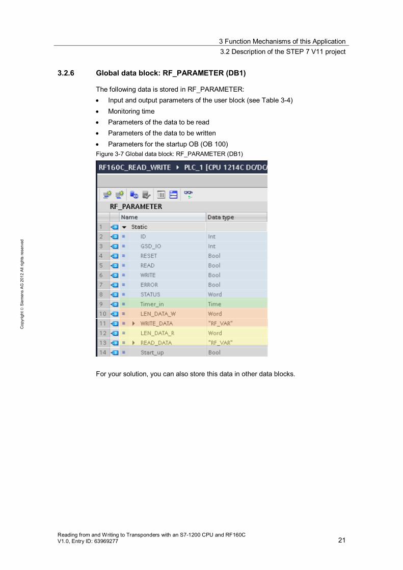
3.2.6 Global data block: RF_PARAMETER (DB1)
The following data is stored in RF_PARAMETER: Input and output parameters of the user block (see Table 3-4) Monitoring time Parameters of the data to be read Parameters of the data to be written Parameters for the startup OB (OB 100)
Figure 3-7 Global data block: RF_PARAMETER (DB1)
For your solution, you can also store this data in other data blocks.

3 Function Mechanisms of this Application 3.2 Description of the STEP 7 V11 project
22 Reading from and Writing to Transponders with an S7-1200 CPU and RF160C
V1.0, Entry ID: 63969277
Cop
yrig
ht
Sie
men
s A
G 2
012
All
right
s re
serv
ed
3.2.7 Configuration and project engineering of the SIMATIC Panel
Overview The application is operated using a configured SIMATIC KTP 1000 TouchPanel. The following table shows the screens of the SIMATIC Panel.
Table 3-6
Name/description Note
Start screen This screen appears automatically after starting the HMI simulator. RFID_Application:
Open Factory_Overview Support:
Open support information
Change language
Overview Factory_Overview This screen provides an overview of the automation task.
Open start screen
Open support information
Open RFID_Station
Change language
3 Function Mechanisms of this Application 3.2 Description of the STEP 7 V11 project
Reading from and Writing to Transponders with an S7-1200 CPU and RF160C V1.0, Entry ID: 63969277 23
Cop
yrig
ht
Sie
men
s A
G 2
012
All
right
s re
serv
ed
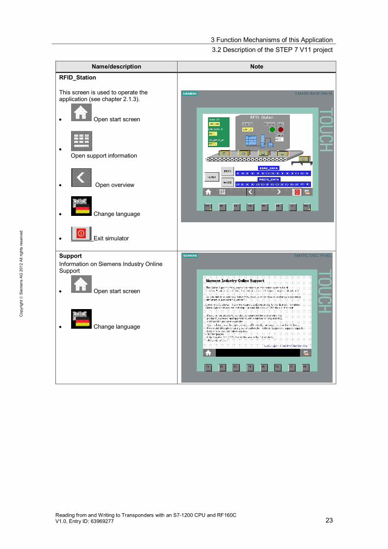
Name/description Note
RFID_Station This screen is used to operate the application (see chapter 2.1.3).
Open start screen
Open support information
Open overview
Change language
Exit simulator
Support Information on Siemens Industry Online Support
Open start screen
Change language

3 Function Mechanisms of this Application 3.2 Description of the STEP 7 V11 project
24 Reading from and Writing to Transponders with an S7-1200 CPU and RF160C
V1.0, Entry ID: 63969277
Cop
yrig
ht
Sie
men
s A
G 2
012
All
right
s re
serv
ed
Human machine interface The data for visualization is stored in the variables of the RF_PARAMETER (DB1) data block (see Figure 3-7). These variables are integrated into WinCC Professional V11 SP2 and form the HMI. The following tags are used in the RFID_Station screen: Table 3-7
HMI tag RF_PARAMETER variable
TIMER IN RF_PARAMETER.Timer_in LEN_DATA_R RF_PARAMETER.LEN_DATA_R LEN_DATA_W RF_PARAMETER.LEN_DATA_W Error RF_PARAMETER.ERROR Status RF_PARAMETER.STATUS RESET RF_PARAMETER.RESET READ RF_PARAMETER.READ WRITE RF_PARAMETER.WRITE READ_DATA RF_PARAMETER.READ_DATA[1..15] WRITE_DATA RF_PARAMETER.WRITE_DATA[1..15]

3 Function Mechanisms of this Application 3.3 Error and status display
Reading from and Writing to Transponders with an S7-1200 CPU and RF160C V1.0, Entry ID: 63969277 25
Cop
yrig
ht
Sie
men
s A
G 2
012
All
right
s re
serv
ed
3.3 Error and status display
For error diagnostics, the RF160C_RW (FB160) function block has a STATUS output. Read the STATUS output of the function block to be provided with information on error messages of the RF160C_RW (FB160) function block and the function
blocks of the library error messages of the RF160C or connected readers.
3.3.1 Error messages of the FB RF160C_RW (FB160) function block and the function blocks of the library
Table 3-8
STATUS Meaning Remedy
16#8101 The length of the data block (LEN_DATA) is outside the range of the “Data” variable in the RF_VAR data structure.
Adjust the length of the “Data” RF_VAR variable (“63969277_RF160C_S71200_Library_en.pdf”, chapter 3.5) \1\ or enter a LEN_DATA within the valid range (1..1000).
16#8102 The previous job has not yet been completed.
Wait until BUSY=FALSE Restart process
Libr
ary
16#8103 No transponder in the field. Appli-cation
16#W#80xy 16#W#87xy 16#W#85xy
Error messages of the extended instructions DPRD_DAT and DPWR_DAT.
Online help in STEP 7
16#25xy Error messages of the GetErrorID instruction.
Online help in STEP 7 Syst
em
func
tions
16#0500 After startup of the RF160C, no RESET is performed (see also \3\, chapter 6.4.2)
Start reset function
RF1
60C
3.3.2 Error messages of the RF160C or connected readers
The reported errors (STATUS, 16#xx00) can be generated either directly by the RF160C or they are provided by the connected reader and transferred by the RF160C. In the first case, the ERR_LED of the RF160C indicates an error; in the other case, the ERR_LED of the reader is activated. For a more detailed overview of these errors, please refer to the following manual: “SIMATIC Sensors RF160C with FC44” (see \3\, chapter 6.4.2).
4 Installation and Commissioning 4.1 Hardware configuration
26 Reading from and Writing to Transponders with an S7-1200 CPU and RF160C
V1.0, Entry ID: 63969277
Cop
yrig
ht
Sie
men
s A
G 2
012
All
right
s re
serv
ed
4 Installation and Commissioning
4.1 Hardware configuration
For the necessary hardware components, please refer to chapter 2.3 (Hardware and software components used).
NOTICE Follow the installation guidelines for S7-1200 (\6\) and RF160C (\3\). Refer to the relevant manuals.
NOTICE Before you switch on the power supply, complete and check the installation!
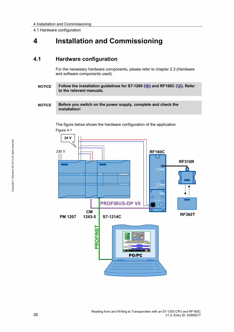
The figure below shows the hardware configuration of the application. Figure 4-1
PROFIBUS-DP V0
RF310R
RF360T
RF160C
S7-1214CCM
1243-5PM 1207
230 V
24 V
PRO
FIN
ET
PG/PC
4 Installation and Commissioning 4.2 Installation of the standard software
Reading from and Writing to Transponders with an S7-1200 CPU and RF160C V1.0, Entry ID: 63969277 27
Cop
yrig
ht
Sie
men
s A
G 2
012
All
right
s re
serv
ed
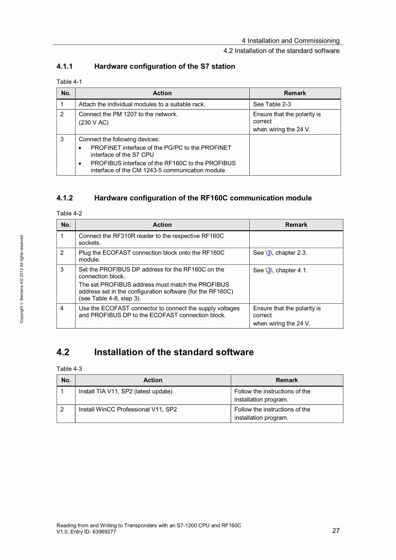
4.1.1 Hardware configuration of the S7 station
Table 4-1
No. Action Remark
1 Attach the individual modules to a suitable rack. See Table 2-3 2 Connect the PM 1207 to the network.
(230 V AC) Ensure that the polarity is correct when wiring the 24 V.
3 Connect the following devices: PROFINET interface of the PG/PC to the PROFINET
interface of the S7 CPU PROFIBUS interface of the RF160C to the PROFIBUS
interface of the CM 1243-5 communication module
4.1.2 Hardware configuration of the RF160C communication module
Table 4-2
No. Action Remark
1 Connect the RF310R reader to the respective RF160C sockets.
2 Plug the ECOFAST connection block onto the RF160C module.
See \3\, chapter 2.3.
3 Set the PROFIBUS DP address for the RF160C on the connection block. The set PROFIBUS address must match the PROFIBUS address set in the configuration software (for the RF160C) (see Table 4-8, step 3).
See \3\, chapter 4.1.
4 Use the ECOFAST connector to connect the supply voltages and PROFIBUS DP to the ECOFAST connection block.
Ensure that the polarity is correct when wiring the 24 V.
4.2 Installation of the standard software Table 4-3
No. Action Remark
1 Install TIA V11, SP2 (latest update) Follow the instructions of the installation program.
2 Install WinCC Professional V11, SP2 Follow the instructions of the installation program.
4 Installation and Commissioning 4.3 Installation of the STEP 7 V11 project
28 Reading from and Writing to Transponders with an S7-1200 CPU and RF160C
V1.0, Entry ID: 63969277
Cop
yrig
ht
Sie
men
s A
G 2
012
All
right
s re
serv
ed
4.3 Installation of the STEP 7 V11 project
The following table lists the steps necessary to install the STEP 7 V11 project. Table 4-4
No. Procedure
1 The STEP 7 V11 project is available on the HTML page from which you downloaded this document. Save the 63969277_RF160C_RW_CODE_V1_0.zip project to your hard drive.
2 Unzip the project. 3 In TIA Portal V11, open the STEP 7 V11 project.
“Project > Open > Browse” 4 The project is now available to you.
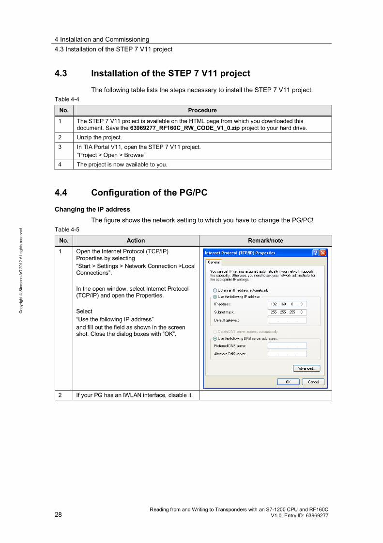
4.4 Configuration of the PG/PC
Changing the IP address The figure shows the network setting to which you have to change the PG/PC!
Table 4-5
No. Action Remark/note
1 Open the Internet Protocol (TCP/IP) Properties by selecting “Start > Settings > Network Connection >Local Connections”. In the open window, select Internet Protocol (TCP/IP) and open the Properties. Select “Use the following IP address” and fill out the field as shown in the screen shot. Close the dialog boxes with “OK”.
2 If your PG has an IWLAN interface, disable it.

4 Installation and Commissioning 4.5 Configuration of the S7 station
Reading from and Writing to Transponders with an S7-1200 CPU and RF160C V1.0, Entry ID: 63969277 29
Cop
yrig
ht
Sie
men
s A
G 2
012
All
right
s re
serv
ed
4.5 Configuration of the S7 station
Note It is not necessary to make the following settings in the application example, as they are already included in the project. This chapter is for information only.
Changing the IP address of the CPU Before the STEP 7 project can be downloaded to the CPU, you have to change the IP address of the S7-1200 CPU via which the project is downloaded to the CPU.
Table 4-6
No. Action
1 In TIA Portal, open the Device configuration of the PLC_1 [CPU 1214C DC/DC/DC] station.
2 In the Device view, double-click on the PROFINET interface of the CPU.
The “Properties > Ethernet addresses” window opens.
4 Installation and Commissioning 4.5 Configuration of the S7 station
30 Reading from and Writing to Transponders with an S7-1200 CPU and RF160C
V1.0, Entry ID: 63969277
Cop
yrig
ht
Sie
men
s A
G 2
012
All
right
s re
serv
ed
No. Action
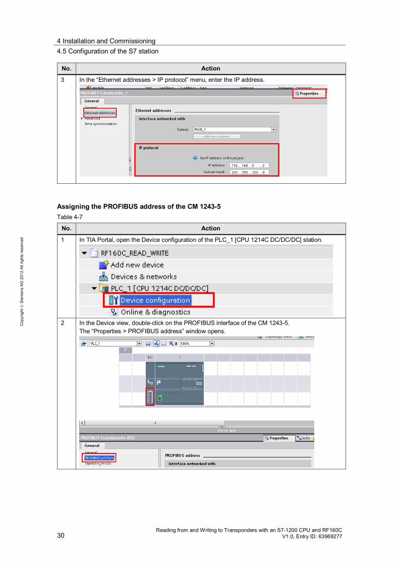
3 In the “Ethernet addresses > IP protocol” menu, enter the IP address.
Assigning the PROFIBUS address of the CM 1243-5 Table 4-7
No. Action
1 In TIA Portal, open the Device configuration of the PLC_1 [CPU 1214C DC/DC/DC] station.
2 In the Device view, double-click on the PROFIBUS interface of the CM 1243-5.
The “Properties > PROFIBUS address” window opens.

4 Installation and Commissioning 4.6 Parameterization of the RF160C communication module
Reading from and Writing to Transponders with an S7-1200 CPU and RF160C V1.0, Entry ID: 63969277 31
Cop
yrig
ht
Sie
men
s A
G 2
012
All
right
s re
serv
ed
No. Action
3 In the “PROFIBUS address > Parameters” menu, enter the PROFIBUS address.
4.6 Parameterization of the RF160C communication module
Before you start parameterizing the RF160C, install the SIEM818A.GSD GSD file, “http://www.automation.siemens.com/mcms/topics/en/comdec/downloads > GSD Files > PROFIBUS > IDENT > RF160C”, if the RF160C is not yet listed in the hardware catalog.
Note It is not necessary to make the following settings in the application example, as they are already included in the project. This chapter is for information only.
Table 4-8
No. Action
1 In TIA Portal, open the Device configuration of the PLC_1 [CPU 1214C DC/DC/DC] station in the Network view.

4 Installation and Commissioning 4.6 Parameterization of the RF160C communication module
32 Reading from and Writing to Transponders with an S7-1200 CPU and RF160C
V1.0, Entry ID: 63969277
Cop
yrig
ht
Sie
men
s A
G 2
012
All
right
s re
serv
ed
No. Action
2 Double-click on the RF160C communication module. The Properties window of the RF160C opens.
3 In the “Properties > PROFIBUS address” menu, enter the PROFIBUS address of the RF160C.
This address must match the PROFIBUS DP address set on the connection block of the RF160C (see Table 4-2).
4 Set the DP interrupt mode of the RF160C to DPV0.

4 Installation and Commissioning 4.7 Downloading the STEP 7 V11 project to the S7 CPU
Reading from and Writing to Transponders with an S7-1200 CPU and RF160C V1.0, Entry ID: 63969277 33
Cop
yrig
ht
Sie
men
s A
G 2
012
All
right
s re
serv
ed
No. Action
5 In the “Device-specific parameters” menu, set the additional parameters the identification systems require (see \3\, chapter 5.2).
4.7 Downloading the STEP 7 V11 project to the S7 CPU
Prerequisite: The STEP 7 V11 project has already been installed and unzipped (see
Installation of the STEP 7 V11 project). The PG/PC is connected to the S7-1200 CPU via the PROFINET interface
(see Configuration of the PG/PC and Configuration of the S7 station). The settings necessary for the RF160C have already been made (see
Parameterization of the RF160C communication module). Procedure: Start TIA Portal Open the Project view Open the “RF160C_READ_WRITE” project In the Project tree:
– Select “PLC_1 [CPU 1214C DC/DC/DC]” – Right-click and select:
“Download to device > all”
5 Operation of the Application 5.1 Starting the HMI simulation
34 Reading from and Writing to Transponders with an S7-1200 CPU and RF160C
V1.0, Entry ID: 63969277
Cop
yrig
ht
Sie
men
s A
G 2
012
All
right
s re
serv
ed
5 Operation of the Application Introduction
This chapter shows you how to operate the above-described functions of this application. The application is operated using a configured SIMATIC KTP 1000 TouchPanel run in simulation mode directly on the programming device. Alternatively, you can operate the application using a watch table.
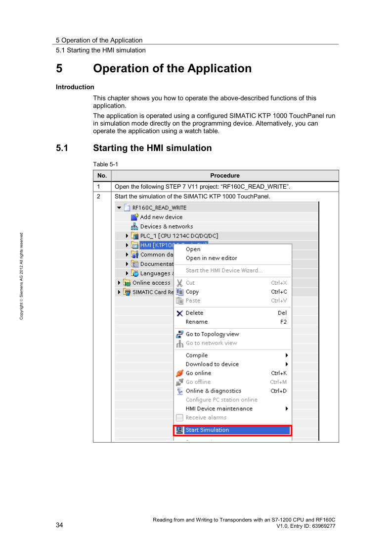
5.1 Starting the HMI simulation Table 5-1
No. Procedure
1 Open the following STEP 7 V11 project: “RF160C_READ_WRITE”. 2 Start the simulation of the SIMATIC KTP 1000 TouchPanel.

5 Operation of the Application 5.2 Watch table
Reading from and Writing to Transponders with an S7-1200 CPU and RF160C V1.0, Entry ID: 63969277 35
Cop
yrig
ht
Sie
men
s A
G 2
012
All
right
s re
serv
ed
No. Procedure
3 Open the “RFID_Station” operating screen “Start screen > RFID_Application > right arrow key”.
5.2 Watch table
Alternatively, you can use the “Watch_Table_RF160C_RW” table to monitor or modify the variables of DB RF_PARAMETER (DB1). Figure 5-1 Watch_Table_RF160C_RW watch table
Open the table as follows:
Open the Project tree Open “PLC_1 [CPU1214C DC/DC/DC]” Open “Watch and force tables” Open the “Watch_Table_RF160C_RW” table Select “Go online” Select “Monitor all”
5 Operation of the Application 5.3 Resetting the RF160C communication module
36 Reading from and Writing to Transponders with an S7-1200 CPU and RF160C
V1.0, Entry ID: 63969277
Cop
yrig
ht
Sie
men
s A
G 2
012
All
right
s re
serv
ed
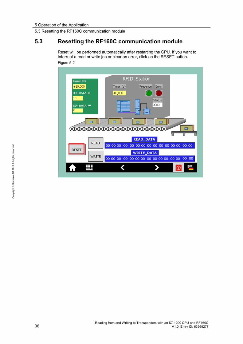
5.3 Resetting the RF160C communication module
Reset will be performed automatically after restarting the CPU. If you want to interrupt a read or write job or clear an error, click on the RESET button. Figure 5-2

5 Operation of the Application 5.4 Reading RFID data from the transponder
Reading from and Writing to Transponders with an S7-1200 CPU and RF160C V1.0, Entry ID: 63969277 37
Cop
yrig
ht
Sie
men
s A
G 2
012
All
right
s re
serv
ed
5.4 Reading RFID data from the transponder
The table below lists instructions for reading RFID data from the transponder. Table 5-2
No. Procedure
1 In the input fields, enter the values relevant to reading the RFID data.
2 Click on the READ button.
3 The read RFID data is available to you in the READ_DATA area.

5 Operation of the Application 5.5 Writing RFID data to the transponder
38 Reading from and Writing to Transponders with an S7-1200 CPU and RF160C
V1.0, Entry ID: 63969277
Cop
yrig
ht
Sie
men
s A
G 2
012
All
right
s re
serv
ed
5.5 Writing RFID data to the transponder
The table below lists instructions for writing RFID data to the transponder. Table 5-3
No. Procedure
1 In the input fields, enter the values relevant to writing the RFID data.
2 Click on the WRITE button.
5 Operation of the Application 5.6 Error while reading RFID data
Reading from and Writing to Transponders with an S7-1200 CPU and RF160C V1.0, Entry ID: 63969277 39
Cop
yrig
ht
Sie
men
s A
G 2
012
All
right
s re
serv
ed
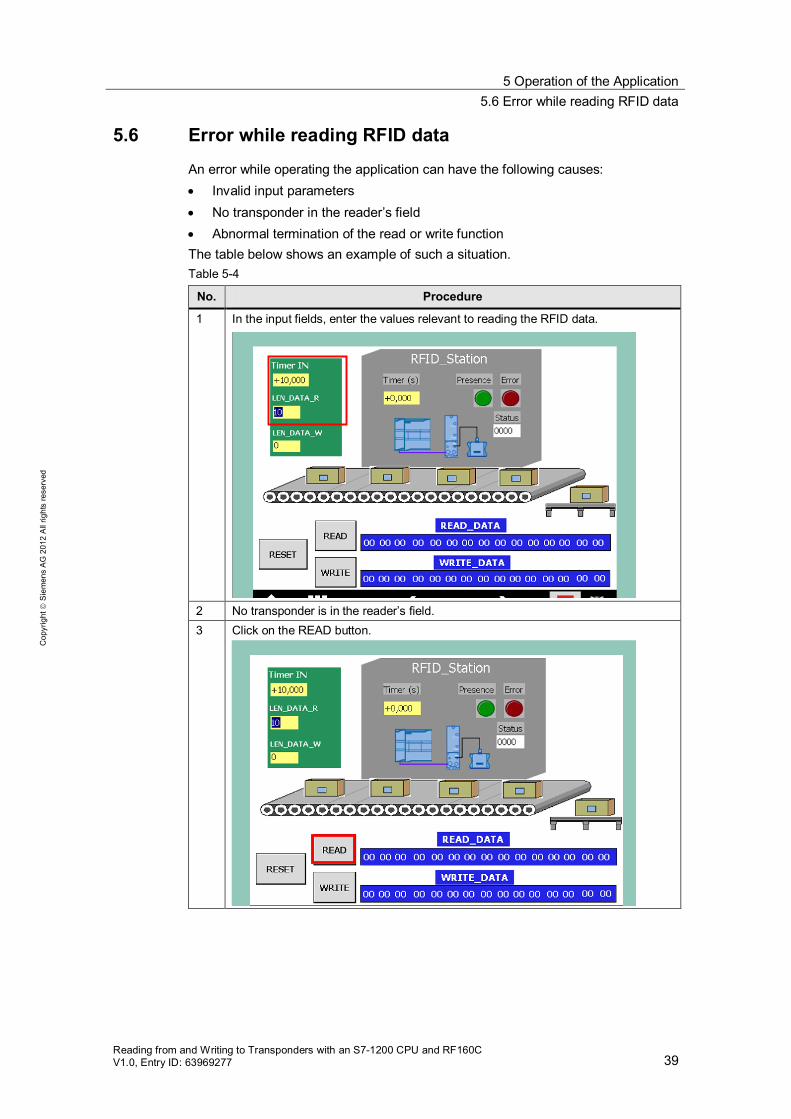
5.6 Error while reading RFID data
An error while operating the application can have the following causes: Invalid input parameters No transponder in the reader’s field Abnormal termination of the read or write function
The table below shows an example of such a situation. Table 5-4
No. Procedure
1 In the input fields, enter the values relevant to reading the RFID data.
2 No transponder is in the reader’s field. 3 Click on the READ button.

5 Operation of the Application 5.6 Error while reading RFID data
40 Reading from and Writing to Transponders with an S7-1200 CPU and RF160C
V1.0, Entry ID: 63969277
Cop
yrig
ht
Sie
men
s A
G 2
012
All
right
s re
serv
ed
No. Procedure
4 An error has occurred: Error_LED: ON Status: 8103 -> No transponder in the reader’s field
5 Place a transponder in the reader’s field and once again click on the READ button.
The error has been cleared.
6 The read RFID data is available to you in the READ_DATA area.
6 References
Reading from and Writing to Transponders with an S7-1200 CPU and RF160C V1.0, Entry ID: 63969277 41
Cop
yrig
ht
Sie
men
s A
G 2
012
All
right
s re
serv
ed
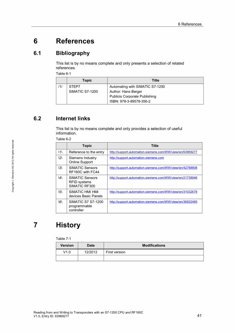
6 References 6.1 Bibliography
This list is by no means complete and only presents a selection of related references. Table 6-1
Topic Title
/1/ STEP7 SIMATIC S7-1200
Automating with SIMATIC S7-1200 Author: Hans Berger Publicis Corporate Publishing ISBN: 978-3-89578-356-2
6.2 Internet links
This list is by no means complete and only provides a selection of useful information. Table 6-2
Topic Title
\1\ Reference to the entry http://support.automation.siemens.com/WW/view/en/63969277
\2\ Siemens Industry Online Support
http://support.automation.siemens.com
\3\ SIMATIC Sensors RF160C with FC44
http://support.automation.siemens.com/WW/view/en/42788808
\4\ SIMATIC Sensors RFID systems SIMATIC RF300
http://support.automation.siemens.com/WW/view/en/21738946
\5\ SIMATIC HMI HMI devices Basic Panels
http://support.automation.siemens.com/WW/view/en/31032678
\6\ SIMATIC S7 S7-1200 programmable controller
http://support.automation.siemens.com/WW/view/en/36932465
7 History Table 7-1
Version Date Modifications
V1.0 12/2012 First version