minor connectors -...
TRANSCRIPT

!
DR. LUMA NASSRAT
ASSISSTANT LECTURER, DEPARTMENT OF PROSTHODONTICSCOLLEGE OF DENTISTRY
TIKRIT UNIVERSITY
PG. !0
RPD LEC.8 | PROSTHODONTICS | 24-12-2018
Minor Connectors3RD GRADE
LEC. 8
Minor Connectors
Definition:
• Any rigid component that links between the major connector or base of RPD
and other components of the prosthesis.
• Or: The portion of a PD framework that supports the clasp and the occlusal
rest.
Rigidity is an important characteristic of all minor connectors as it aids in force
distribution. So, any bending or deformation will lead to concentration of forces.
Function:
1. Primary function is to join units of the prosthesis and denture base to the
major connector.
2. Transfer functional stresses to abutment teeth.
3. Transfer the effect of the retainers, rests & stabilizing components to the
prosthesis.
4. Distribute stresses on the edentulous ridge to the ridge & remaining teeth.
Types of minor connectors:
There are four categories of minor connectors. They may be
described as follows:
1. Minor connectors that join clasp assemblies to major Connectors.
2. Minor connectors that join indirect retainers or auxiliary rests to major
connectors.
3. Minor connectors that join denture bases to major connectors.
4. Minor connectors that serve as approach arms for vertical projection/bar-type
clasps.
PG. !1HTPP://CDEN.TU.EDU.IQ

1. Minor Connector joining Clasp Assemblies to Major Connector:
They must be rigid, because they support the active components of the
removable partial denture, the retentive clasps. They also support the rests,
which prevent vertical movement of a prosthesis toward the underlying tissues.
As a result, minor connectors must have sufficient bulk to ensure rigidity, yet
they must be positioned so they do not irritate the oral tissues.
Most minor connectors that support clasp assemblies are located on
proximal surfaces of teeth adjacent to edentulous areas. These minor
connectors should be broad buccolingually, but thin mesiodistally. The resultant
shape makes it easier to place a prosthetic tooth in a natural position.
In many instances, a clasp assembly must be positioned on a tooth that
is not adjacent to an edentulous space. When this occurs, a minor connector
should be positioned in the associated lingual embrasure. This results in a
sufficient bulk of metal without encroaching on the tongue space. Hence, the
minor connector may be rigid yet unobtrusive.
A minor connector should never be positioned on the convex lingual
surface of a tooth where its bulk will be evident.
! !
PG. !2HTPP://CDEN.TU.EDU.IQ

2. Minor Connector joining Indirect Retainers or Auxiliary Rests to
Major Connectors:
They should form right angles with the corresponding major
connectors, but junctions should be gently curved to prevent
stress concentration. As previously noted, minor connectors
should be positioned in lingual embrasures to disguise their bulk
and promote patient comfort.
!
3. Minor Connector joining Denture Base to Major Connectors:
Described as follows:
1. Open construction.
2. Mesh construction.
3. Bead, wire, or nailhead components on a metal base.
These minor connectors must be strong enough to anchor a denture base to
the removable partial denture framework. They must be rigid enough to resist
fracture and displacement. In addition, these components must provide
minimal interference with the arrangement of artificial teeth.
In the maxillary arch, a distal extension base must extend the entire length
of the ridge and should cover the tuberosity. Consequently, the minor
connector should be extended as far posteriorly as is practical. In many
PG. !3HTPP://CDEN.TU.EDU.IQ

instances, the minor connector may extend beyond the most prominent portion
of the tuberosity. In other cases, the minor connector must be terminated
anterior to this area.
In the mandibular arch, a distal extension base must cover the retromolar
pad. Therefore, the minor connector should extend two-thirds the length of the
edentulous ridge. This provides adequate support and retention for the
associated resin base.
1.Open Construction
Open construction consists of longitudinal and transverse struts that form a
ladder-like network. Placement of the longitudinal and transverse struts is a critical
factor in prosthetic tooth arrangement.
In the mandibular arch, one longitudinal strut should be positioned buccal to
the crest of the ridge and the other lingual to the ridge crest. In the maxillary arch,
one longitudinal strut should be positioned buccal to the ridge crest. The border of
the major connector generally will act as the second longitudinal strut. Positioning of
a longitudinal strut along the crest of the ridge must be avoided. This not only
interferes with the placement of artificial teeth, but also predisposes the denture
base to fracture.
Transverse struts also must be positioned to facilitate the placement of
artificial teeth. When there is adequate room for the placement of teeth, the number
of cross struts is not critical. When vertical space is minimal, improperly placed struts
may create difficulties in tooth placement. Ideally, transverse struts should be
designed to pass between the necks of the artificial teeth. This aids in tooth
arrangement and often results in improved esthetics.
During the framework fabrication process, those areas of a master cast that are
to feature open retention must be relieved using an appropriate thickness of wax.
PG. !4HTPP://CDEN.TU.EDU.IQ
Relief provides space between the completed minor connector and the tissues of the
residual ridge. The space permits an acrylic resin to encircle the longitudinal and
transverse struts, thereby providing retention for the denture base.
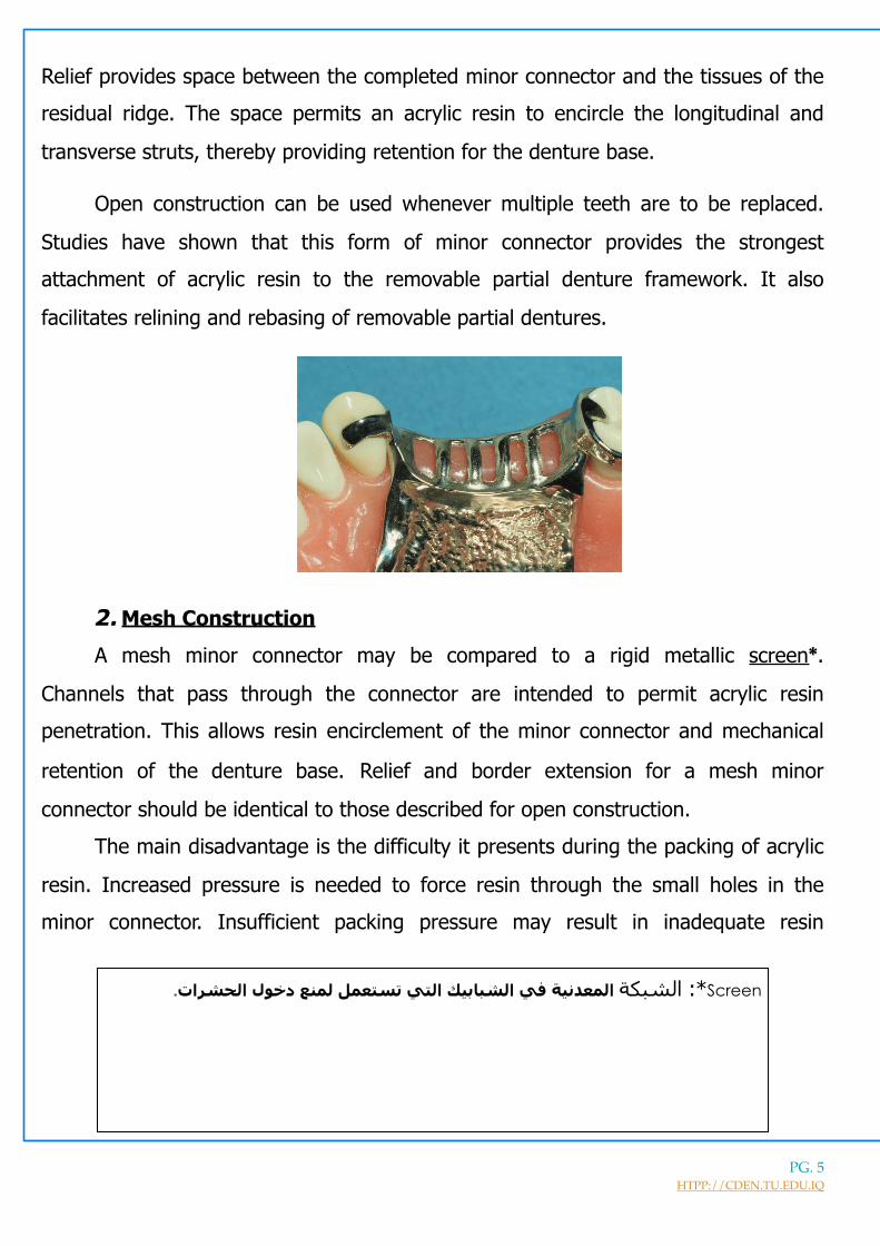
Open construction can be used whenever multiple teeth are to be replaced.
Studies have shown that this form of minor connector provides the strongest
attachment of acrylic resin to the removable partial denture framework. It also
facilitates relining and rebasing of removable partial dentures.
!
2.Mesh Construction
A mesh minor connector may be compared to a rigid metallic screen*.
Channels that pass through the connector are intended to permit acrylic resin
penetration. This allows resin encirclement of the minor connector and mechanical
retention of the denture base. Relief and border extension for a mesh minor
connector should be identical to those described for open construction.
The main disadvantage is the difficulty it presents during the packing of acrylic
resin. Increased pressure is needed to force resin through the small holes in the
minor connector. Insufficient packing pressure may result in inadequate resin
PG. !5HTPP://CDEN.TU.EDU.IQ
Screen*: الشبكة المعدنیة في الشبابیك التي تستعمل لمنع دخول الحشرات.

penetration and a weak attachment to the framework. Studies have shown that the
smaller the openings in this minor connector, the weaker the attachment.
Mesh construction also may interfere with the arrangement of prosthetic teeth.
Mesh must cover the entire ridge crest and cannot be limited to those areas between
the necks of artificial teeth. As a result, the ridge lap areas of artificial teeth may
require significant reduction to facilitate proper arrangement. When restorative space
is minimal, this reduction may be significant and may result in compromised
esthetics.
Mesh construction may be used whenever multiple teeth are to be
replaced. Nevertheless, open construction is preferred.
!
➢ Tissue Stoppers (Cast Stops):
When providing relief under the RPD framework, there is a difference between
tooth-supported RPD and distal extension RPD, as in the latter the minor
connector is supported from one end so it may bend under load and acrylic
packing and processing. To prevent this a small area the free end of the minor
connector should contact the master cast. This area that resembles a small
square metal projection is termed as tissue stopper or cast stops. Formed
by removing a (2×2 mm.) of relief wax.
PG. !6HTPP://CDEN.TU.EDU.IQ

! !
! !
!
3.Beads and nail heads:
They are often used in conjunction with metal denture bases. The metal bases
are cast to fit directly against the underlying soft tissues. Hence, no relief is provided
PG. !7HTPP://CDEN.TU.EDU.IQ

beneath these minor connectors. Resin is attached to the free surface of such bases,
and retention is gained by encompassment of surface projections.
Projections may be created by placing resin beads on the appropriate segments
of the wax pattern, investing the completed pattern, eliminating the pattern materials
via heat application, and casting the framework. Nailheads may be produced in a
similar manner. Projections also may be added by casting or soldering irregular wire
forms to a metal base.
The primary advantage of a metal base is related to improved hygiene and
enhanced thermal stimulation. Disadvantages include difficulty in adjusting and
relining cast metal bases. Furthermore, the attachment of resin is relatively weak.
Bead, nailhead, and wire construction should be limited to short-
span, tooth-supported applications in patients with well-healed ridges.
! !
Attachment of minor connectors to major connectors: A minor connector that supports an acrylic resin denture base must be joined
to the major connector with sufficient bulk to avoid fracture. In addition, each acrylic
resin denture base must join the major connector in a smooth, even fashion. Any
irregularity or “step” between the two surfaces will irritate the tongue or the soft
tissues of the ridge. Consequently, the interfacial geometry and material properties
must be considered.
PG. !8HTPP://CDEN.TU.EDU.IQ

Currently, acrylic resin is used to construct the overwhelming majority of
denture bases. Because acrylic resin gains its strength with increasing bulk, it should
not be finished to a thin edge. If this is attempted, the material may chip or fracture.
This can create unhygienic and potentially irritating conditions.
To prevent the acrylic resin from becoming too thin, the design of the resin-
metal interface must be considered. Ideally, a butt joint should be provided so the
acrylic resin can blend evenly with the major connector. Because acrylic resin is
processed completely around open minor connectors and mesh minor connectors,
resin-metal interfaces must be created on both the internal and external surfaces of
the associated major connectors. For metal base minor connectors, acrylic resin is
processed only on the external surface. Therefore, resin-metal joints should be
created only at the external surfaces.
These interfaces are referred to as finish lines. If they are located on
the outer surfaces of major connectors, they are called external finish
lines. If they are positioned on the inner or tissue surfaces, they are
termed internal finish lines.
✓ Internal finishing line: Formed as a result of relief wax placed on edentulous
ridges of a master cast prior to duplication, wax will form an elevated area on
the refractory cast, the margins create internal finishing lines in the metal
frame. They should be sharp and well defined.
! !
external finishing line internal finishing line External finishing line
PG. !9HTPP://CDEN.TU.EDU.IQ

! (tissue-side of the denture metallic framework)
External finishing line:
Must be sharp and should be slightly undercut to help lock the acrylic resin to the
major connector. The internal angle formed at the junction of the major and minor
connectors should be less than 90 degrees.
An external finish line is formed by the placement and carving of wax during
framework fabrication. It should originate at the lingual extent of the rest seat and
continue down the lingual aspect of the minor connector. The external finish line
should be well defined along its entire length.
The contour of the external finish line should be consistent with the contours of
the major connector. Transition from the external finish line to a denture base should
be smooth and flowing.
When viewed from an occlusal perspective, the external finish line should follow
an arc established by the lingual surfaces of the remaining teeth. This permits the
development of contours that are not irritating to the patient.
4. Minor Connectors that Serve as approach arm for vertical projection /
bar –type clasp:
Approach arms for vertical projection/bar-type clasps are the only minor
connectors that are not required to be rigid. These components support direct
retainers (clasps) and therefore must exhibit some degree of flexibility.
PG. !10HTPP://CDEN.TU.EDU.IQ

A minor connector of this type approaches the tooth from an apical
direction rather than from an occlusal direction. The approach arm should
display a smooth, even taper from its origin to its terminus. It must not cross a
soft tissue undercut, and for this reason its use is contraindicated in some
instances.
! !
REFERENCES: Stewart's Clinical Removable Partial Prosthodontics. CH.2
PG. !11HTPP://CDEN.TU.EDU.IQ