re 92 064/11 - gerex · data sheet for variable pump a4vso ... nominal pressure 350 bar peak...
TRANSCRIPT

Linear Motion andAssembly Technologies ServicePneumaticsHydraulics
Electric Drives and Controls
Power controlLR2, LR3, LR2N and LR3N
Data sheet
for variable pump A4VSO Series 1 and 3Size 40 to 1000Nominal pressure 350 barPeak pressure 400 baropen circuit operation
RE 92 064/11.07 1/68Replaces: 05.98
Features– Power control with hyperbolic characteristic
– The power control varies the pump displacement, dependent on output pressure in such a manner, that a specified drive power at constant speed cannot be exceeded
– Power settings from min. to max. with one spring
– Supplementary functions in a modular system, eg.:
• hydraulic remote control
• pressure control
• flow control
• hydraulic stroke limiter
• mechanical stroke limiter
• hydraulic two-point control
• electric control of pilot pressure
Further information:
Variable pump A4VSO Size 40 to 1000 RE 92 050
ContentsOrdering code – Standard program LR2 and LR3 2
Ordering code – Standard program LR2N and LR3N 3
LR2 Power control, with hyperbolic characteristic 4
LR3 with remote control of power characteristic 11
LR.D with pressure control 15
LR.G with remote pressure control 17
LR.F with flow control 21
LR.H with hydraulic stroke limiter 24
LR.M with mechanical stroke limiter Vg max 30
LR.Z Hydraulic two-point control 34
LR.Y Electric two-point control 39
LR.S with Load-Sensing valve 42
LR.N Hydraulic stroke control, pilot pressure dependent 45
LR.NT with electric control of pilot pressure 51
Example of control combination LR2GN 58
Example of control combination LR2GNT 63
Installation notes 67
General notes 68

2/68 Bosch Rexroth AG LR2, LR3, LR2N and LR3N | RE 92 064/11.07
Ordering code – Standard program A4VSO LR2 and LR3
A4VS O LR / –01 02 03 04 05 06 07 08 09 10 11 12 13 14 15 16
01 Fluid (Details see RE 92050)
Axial piston unit
02 Swash plate design, variable A4VS
Type of operation
03 Pump, open circuit (see RE 92050) O
Size 40 71 125 180 250 355 500 750 1000
04 Displacement Vg max [cm3] 40 71 125 180 250 355 500 750 1000
Control devices
05 Power control with hyperbolic characteristic, initial position Vgmax LR
06
Setting of power characteristic
mechanically adjustable 2 2
hydraulic remote control 3 3
07
Pressure control
without pressure control (no code letter)
with pressure control D D
with remote pressure control G G
08
Flow control /stroke limiter
without flow control /stroke limiter(no code letter)
with flow control F – – – F1)
with hydraulic stroke limiter, inverse proportional
H H
with hydraulic two-point control Z Z
with electr. unloading valve for easy start Y Y
with load sensing a. rem. press. control. – S – – – S2)
09
Mechanical stroke limiter
without mechanical stroke limiter(no code letter)
with mechanical stroke limiter M – – – M
1) for a dynamic control we recommend to use the LR.S option2) cannot be combined with pressure control D or G
available in preparation – not available preferred program

RE 92 064/11.07 | LR2, LR3, LR2N and LR3N Bosch Rexroth AG 3/68
Ordering code – Standard program A4VSO LR2N and LR3N
A4VS O LR N / –01 02 03 04 05 06 07 08 09 10 11 12 13 14 15 16
Control devices
05 Power control with hyperbolic characteristic, initial position Vgmin, pilot pressure dependent LR
06
Setting of power characteristic 40 71 125 180 250 355 500 750 1000
mechanically adjustable 2 N 2
hydraulic remote control 3 N 3
07
Pressure control
without press. control (no code letter)
with pressure control D N D
with remote pressure control G N G
08 Hydraulic stroke limiter, proportional N
09
Electric control of pilot pressure
without electr. control of pilot press.(no code letter)
N
with electr. control. (DBEP 6) N T T3)3) only available for clockwise rotation; for operation on HF-fluid please observe RE 29164 (Proportional pressure relief valve type DBEP)
Series 40 71 125 180 250 355 500 750 1000
10of A4VSO – – – – – – – 10
– – 30
11 Direction of rotation
12 Seals
13 Shaft end For details see:RE92050 – A4VSO14 Mounting flange
15 Port for service lines
16 Through drive
available in preparation – not available preferred program
4/68 Bosch Rexroth AG LR2, LR3, LR2N and LR3N | RE 92 064/11.07
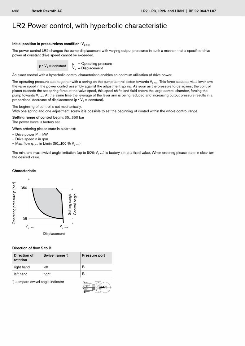
LR2 Power control, with hyperbolic characteristic
Initial position in pressureless condition: Vg max
The power control LR2 changes the pump displacement with varying output pressures in such a manner, that a specified drive power at constant drive speed cannot be exceeded.
p • Vg = constantpVg
= Operating pressure= Displacement
An exact control with a hyperbolic control characteristic enables an optimum utilisation of drive power.
The operating pressure acts together with a spring on the pump control piston towards Vg max. This force actuates via a lever arm the valve spool in the power control assembly against the adjustment spring. As soon as the pressure force against the control piston exceeds the set spring force at the valve spool, this spool shifts and fluid enters the large control chamber, forcing the pump towards Vg min. At the same time the leverage of the lever arm is being reduced and increasing output pressure results in a proportional decrease of displacement (p • Vg = constant).
The beginning of control is set mechanically.With one spring and one adjustment screw it is possible to set the beginning of control within the whole control range.
Setting range of control begin: 35...350 barThe power curve is factory set.
When ordering please state in clear text:
– Drive power P in kW – Drive speed n in rpm– Max. flow qv max in L/min (50...100 % Vg max)
The min. and max. swivel angle limitation (up to 50% Vg max) is factory set at a fixed value. When ordering please state in clear text the desired value.
Characteristic
350
35
Vg min Vg max
Set
ting
rang
eC
ontr
ol b
egin
Ope
ratin
g pr
essu
re p
[ba
r]
Displacement
Direction of flow S to B
Direction of rotation
Swivel range 1) Pressure port
right hand left B
left hand right B
1) compare swivel angle indicator
15°
0° 1
5°
rightleft

RE 92 064/11.07 | LR2, LR3, LR2N and LR3N Bosch Rexroth AG 5/68
LR2 Power control, with hyperbolic characteristicPower characteristics in kW
Size 40 Size 71at 1500 rpm1 at 1500 rpm
Size 125 Size 180at 1500 rpm at 1500 rpm
Size 250 Size 355at 1500 rpm at 1500 rpm
350
300
250
200
150
100
50
00 10 20 30 40 50 60
350
300
250
200
150
100
50
00 20 40 60 80 100 107
350
300
250
200
150
100
50
00 50 100 150 187
350
300
250
200
150
100
50
00 50 100 150 200 250 270
350
300
250
200
150
100
50
00 100 200 300 375
350
300
250
200
150
100
50
00 100 200 300 400 500 532
30
Ope
ratin
g pr
essu
re p
[ba
r]
30
22
15
117,5
18,5
5,5
Ope
ratin
g pr
essu
re p
[ba
r]
Ope
ratin
g pr
essu
re p
[ba
r]
9075
Ope
ratin
g pr
essu
re p
[ba
r]
Ope
ratin
g pr
essu
re p
[ba
r]
Flow qv [L/min]
Ope
ratin
g pr
essu
re p
[ba
r]
Flow qv [L/min]
Flow qv [L/min]
Flow qv [L/min]
Flow qv [L/min]
Flow qv [L/min]
3022
1511
18,5
5545
37
302215
18,5
554537
3022
90
110
554537
75
132
30
90
110
554537
75
132
200160
90110
554537
75
132
200160
250

6/68 Bosch Rexroth AG LR2, LR3, LR2N and LR3N | RE 92 064/11.07
LR2 Power control, with hyperbolic characteristicPower characteristics in kW
Size 500 Size 500 High-Speed-Version HA4VSOat 1000 rpm at 1500 rpm
Size 750 Size 1000at 1000 rpm at 1000 rpm
350
300
250
200
150
100
50
00 100 200 300 400 500
350
300
250
200
150
100
50
00 200 400 600 750
350
300
250
200
150
100
50
00 200 400 600 800 1000
Ope
ratin
g pr
essu
re p
[ba
r]
Ope
ratin
g pr
essu
re p
[ba
r]O
pera
ting
pres
sure
p [
bar]
Flow qv [L/min]
Fow qv [L/min] Flow qv [L/min]
90
110
5537
75
132
200160
250
90110
75
132
220160
250
290
180
90 11075
132
200160
250
315
355
400450
500
350
300
250
200
150
100
50
00 200 400 600 750
Ope
ratin
g pr
essu
re p
[ba
r]
Flow qv [L/min]
90110
5575
132
200160
250
315
355

RE 92 064/11.07 | LR2, LR3, LR2N and LR3N Bosch Rexroth AG 7/68
Schematics LR2
Size 40 and 71 Size 125 to 355A4VSO LR2, Series 1 A4VSO LR2, Series 3
1
R(L)TU S MS K1 K2
MBBB1
Rkv
2
R(L)TU S MS K1 K2M1 M2
MBB
1
B1
3
Rkv
2
Size 500 to 1000A4VSO LR2, Series 3
R(L)TU S MS K1 K2
MBBB1
1
M2M1P
2
PortsRkv External control fluid return (Size 40 to 355)
M1, M2 Gauging ports control chamber press. (Size 125 to 1000)
P Control pressure port (Size 500 to 1000)
Subassemblies1 A4VSO with hydraulic control device
(see RE 92050)
2 Power control valvel
3 Sandwich plate (Size 125 to 355)
Mounting optionN, Y, H or Z
Mounting optionD or G
8/68 Bosch Rexroth AG LR2, LR3, LR2N and LR3N | RE 92 064/11.07
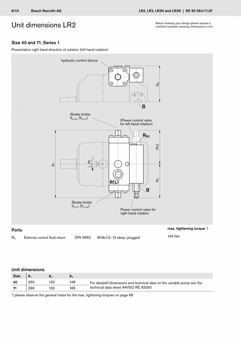
Unit dimensions LR2
Size 40 and 71, Series 1Presentation right hand direction of rotation (left hand rotation)
L(R
)
15
15
0 Einschraubloch M33
B
R(L)
B
Rkv
A1
A2
(A2)
A3
(Power control valve for left hand rotation)
Power control valve for right hand rotation
Ports max. tightening torque 1)
Rkv External control fluid return DIN 3852 M18x1,5; 12 deep; plugged 140 Nm
Unit dimensions Size A1 A2 A3
40 260 132 148 For detailed dimensions and technical data on the variable pump see the technical data sheet A4VSO RE 9205071 296 132 165
1) please observe the general notes for the max. tightening torques on page 68
Before finalising your design please request a certified installation drawing. Dimensions in mm
hydraulic control device
Stroke limiterVg max (Vg min)
Stroke limiter Vg min (Vg max)

RE 92 064/11.07 | LR2, LR3, LR2N and LR3N Bosch Rexroth AG 9/68
Unit dimensions LR2
Size 125 to 355, Series 3 Presentation right hand direction of rotation (left hand rotation)
A3
L(R
)
15
15
0 Einschraubloch M33
M1(M2)
M2(M1)
R(L)
Rkv
B
B
A1
Ports max.tightening torque 1)
Rkv external control fluid return DIN 3852 M18x1,5; 12 deep; plugged 140 Nm
M1; M2 Gauging port control chamber pressure
DIN 3852 M14x1,5; 12 deep plugged (Size 125 a. 180)M18x1,5; 12 deep; plugged (Size 250 u. 355)
80 Nm140 Nm
Unit dimensions Size A1 A3
125 354 195
For detailed unit dimensions and technical data on the variable pump see technical data sheet A4VSO RE 92050
180 354 195
250 424 238
355 424 238
1) please observe the general notes for the max. tightening torques on page 68
(Power control valvefor left hand rotation)
Power control valve for right hand rotation
Hydraulic control device Sandwich plate
Before finalising your design please request a certified installation drawing. Dimensions in mm
Stroke limiterVg max (Vg min)
Stroke limiterVg min (Vg max)

10/68 Bosch Rexroth AG LR2, LR3, LR2N and LR3N | RE 92 064/11.07
Unit dimensions LR2
Size 500 to 1000, Series 3Presentation right hand direction of rotation (left hand rotation)
R(L)
M2(M1)
P
B
M1(M2)
A3
A1
L(R
)
1515
0 Einschraubloch M33
Ports max. tightening torque 1)
M1; M2 Gauging port control chamber pressure DIN 3852 M18x1,5; 12 deep; plugged 140 Nm
P Control pressure port DIN 3852 M22x1,5; 14 deep; plugged 210 Nm
Unit dimensions Size A1 A3
500 510 285For detailed unit dimensions and technical data on the variable pump see technical data sheet A4VSO RE 92050
750 582 322
1000 622 350
1) please observe the general notes for the max. tightening torques on page 68
(Power control valve for left hand rotation)
Power control valve for right hand rotation
hydraulic control device
Before finalising your design please request a certified installation drawing. Dimensions in mm.
Stroke limiter Vg max (Vg min)
Stroke limiter Vg min (Vg max)

RE 92 064/11.07 | LR2, LR3, LR2N and LR3N Bosch Rexroth AG 11/68
LR3 with remote control of power characteristic
Initial position in pressureless condition: Vg max
The power control LR3 can be remotely adjusted by applying an external pilot pressure (pp) at port XLR to the spring chamber of the power control valve.
The beginning of control can be changed in proportion to the applied pilot pressure.
The pilot pressure port XLR may not be plugged.
Maximum external pilot pressure 100 bar
Total range for beginning of control setting: 50... 350 bar
The basic power control curve is factory set, with a pilot pressure signal pp in XLR = 0 bar.
When ordering please state in clear text:
– Drive speed n in rpm– Drive power P in kW with pilot pressure pp in XLR = 0 bar Max. flow qv max in L/min (50...100 % Vg max)
Otherwise the LR3 and the LR2 controls feature the same properties.The min. and max. swivel angle limitations (up to 50% Vg max) are factory set. When ordering please state the required values in clear text.
Characteristic
Displacement
350
50
Vg min Vg max
Ope
ratin
g pr
ess.
p [
bar]
Set
ting
rang
eC
ontr
ol b
egin
Pilo
t pre
ss. i
n X
LR p
pilo
t
Power P
Direction of flow S to B
Power increase through pilot pressure in port XLR
Power increase / pilot pressure (kW/bar)
Size 40 71 125 180 250 355 500 750 1000
n*=1000rpm 0,53 0,78 1,15 1,66 1,83 2,46 5,30 7,5 9,2
n*=1200rpm 0,64 0,94 1,38 1,99 2,19 2,95 6,40 9,0 11,0
n*=1500rpm 0,80 1,18 1,72 2,47 2,74 3,69 8,00 11,25 –
n*=1800rpm 0,96 1,41 2,07 2,98 3,29 4,42 9,60 – –
* Please observe speed limits and perm. flows acc. to RE 92050
Direction of rotation
Swivel range 1) Pressure port
right hand left B
left hand right B
1) Compare swivel angle indicator
15°
0° 1
5°
rightleft

12/68 Bosch Rexroth AG LR2, LR3, LR2N and LR3N | RE 92 064/11.07
Schematics LR3
Size 40 and 71 Size 125 to 355A4VSO LR3, Series 1 A4VSO LR3, Series 3
1
2
R(L)TU S MS K1 K2
MBBB1
Rkv
XLR
R(L)TU S MS K1 K2M1 M2
MBB
1
B1
2
3
RkvXLR
Size 500 to 1000A4VSO LR3, Series 3
R(L)TU S MS K1 K2
MBBB1
1
M2
XLR
M1P
2
PortsXLR Pilot pressure port for remote power control
Rkv External control fluid return (Size 40 to 355)
P Control pressure port (Size 500 to 1000)
M1, M2 Gauging port control chamber pressure (Size 125 to 1000)
Subassemblies1 A4VSO with hydraulic control device
(see RE 92050)
2 Power control valve
3 Sandwich plate (Size 125 to 355)

RE 92 064/11.07 | LR2, LR3, LR2N and LR3N Bosch Rexroth AG 13/68
Unit dimensions LR3
Size 40 and 71, Series 1 Size 125 to 355, Series 3Right hand direction of rotation (left hand) Right hand direction of rotation (left hand)
21
B
XLR
(XLR)
XLR
L(R
)
1515
0A1
A2
(A2)
A5
A3
A4
R(L)
Rkv
XLR
M1(M2)
R(L)
Rkv
B
21
3
XLR
M2(M1)
(XLR)
L(R
)
15
15
0 Einschraubloch M33
A3
A2
(A2)
A1
A4
A5
Subassemblies see page12
Ports max. tightening torque 1)
XLR Pilot pressure port for remote power control
DIN 3852 M14x1,5; 12 deep 80 Nm
Rkv External control fluid return DIN 3852 M18x1,5; 12 deep; plugged 40 Nm
M1; M2 Gauging port control chamber press. DIN 3852 M14x1,5; 12 deep; plugged (Size 125 a. 180)M18x1,5; 12 deep; plugged (Size 250 a. 355)
80 Nm40 Nm
Unit dimensions Size A1 A2 A3 A4 A5
40 260 133 148 106 219
For detailed unit dimensions and technical data on the variable pump see technical data sheet A4VSO RE 92050
71 296 133 165 117 246
125/180 354 133 195 147 315
250/355 424 133 238 183 3771) please observe the general notes for the max. tightening torques on page 68
(Power control valve for left hand rotation)
Power control valve for right hand rotation
(Power control valve for left hand rotation)
Power control valve for right hand rotation
to pump mounting face to pump mounting face
Before finalising your design please request a certified installation drawing. Dimensions in mm.
Stroke limiter Vg max (Vg min)
Stroke limiter Vg min (Vg max)
Stroke limiter Vg max (Vg min)
Stroke limiter Vg min (Vg max)

14/68 Bosch Rexroth AG LR2, LR3, LR2N and LR3N | RE 92 064/11.07
Unit dimensions LR3
Size 500 to 1000, Series 3Right hand direction of rotation (left hand)
A4
R(L)
B
2
1
XLR
(XLR)
XLR
M1(M2)
M2(M1)
A1
A5
L(R
)
15
15
0 Einschraubloch M33
A3
A2
(A2)
Ports max. tightening torque 1)
XLR Pilot pressure port forremote power control
DIN 3852 M14x1,5; 12 deep 80 Nm
M1; M2 Gauging port control chamber pressure
DIN 3852 M18x1,5; 12 deep; plugged 140 Nm
Unit dimensions Size A1 A2 A3 A4 A5
500 510 125 285 207 468For detailed unit dimensions and technical data on the variable pump see technical data sheet A4VSO RE 92050
750 582 125 322 237 502
1000 622 125 350 260 566
1) please observe the general notes for the max. tightening torques on page 68
(Power control valve for left hand rotation)
Power control valve for right hand rotation
Subassemblies1 A4VSO with hydraulic control device
(see RE 92050)
2 Power control valve
3 Sandwich plate (Size 125 to 355)
to pump mounting face
Before finalising your design please request a certified installation drawing. Dimensions in mm.
Stroke limiter Vg max (Vg min)
Stroke limiter Vg min (Vg max)

RE 92 064/11.07 | LR2, LR3, LR2N and LR3N Bosch Rexroth AG 15/68
LR.D with pressure control
Initial position in pressureless condition: Vg max
The pressure control overrides the power control, i.e. below the set pressure control level the unit follows the power control function.
As soon as the pump output pressure reaches the pressure control level, the pump turns into the pressure control mode and delivers only the amount of fluid as required to maintain this pressure.
Setting range of the pressure control 20...350 barThis pressure is set as standard to 350 bar.
If another setting is required please state in clear text when ordering.
Characteristic
Displacement
350
20
Vg min Vg max
Ope
ratin
g pr
ess.
p [
bar]
Set
ting
rang
epr
essu
re c
ontr
ol
Direction of flow S to B
Direction of rotation
Swivel range 1) Pressure port
right hand left B
left hand right B
1) Compare swivel angle indicator
15°
0° 1
5°
rightleft

16/68 Bosch Rexroth AG LR2, LR3, LR2N and LR3N | RE 92 064/11.07
Schematics LR.D
Size 40 and 71 Size 125 to 355Example: A4VSO LR2D Example: A4VSO LR2D
1.1
4
R(L)TU S MS K1 K2
MBBB1
2
1
4
R(L)TU S MS K1 K2M1 M2
MBBB1
2
3
Size 500 to 1000Example: A4VSO LR2D
1
R(L)TU S MS K2K1
M2MBBB1
2
4
M1P
X X
PortsM1, M2 Gauging port control chamber pressure
(Size 125 to 1000)
P Control pressure port (Size 500 to 1000)
Unit dimensions LR.D see page 19
Subassemblies1 A4VSO with hydraulic control device
(see RE 92050)
2 Power control valve
3 Sandwich plate (Size 125 to 355)
4 Pressure control valve

RE 92 064/11.07 | LR2, LR3, LR2N and LR3N Bosch Rexroth AG 17/68
LR.G with remote pressure control
Initial position in pressureless condition: Vg max
In order to enable a remote setting of the pressure control an external relief valve (item 5) can be piped to port XD. This relief valve does not belong to the standard supply of the LR2G- or LR3G-control, if desired however it can be mounted depending on the pump version.As soon as the pressure control level (relief valve setting plus pressure differential over the pressure control valve spool) is rea-ched the pump turns into the pressure control mode.
The pressure differential over the pressure control valve spool (item 4) is set as standard to 20 bar, this results in a pilot oil flow of approx. 1.5 L/min. out of port XD If another setting is desired (recommended range 20...50 bar), please state the desired value in clear text.
As separate pressure relief valve we recommend:– DBD 6 (hydraulic) to RE 25402.– DBETR–SO 437 (electric) to RE 29166
The max. line lenght should not exceed 2 m.
Notes for the remote pressure control settings :The overall level of the pressure control setting is a result of the separate relief valve setting plus the differential pressure Dp at the pressure control valve spool-Example: external pressure relief valve 330 bar
Differential pressure at pressure control valve 20 bar
results in pressure control of 330 + 20 = 350 bar
Please observe the following in control combinations with hydraulic stroke limiting (LR.GH or LR.GN):
With a pressure control setting below the pressure level of the external control pressure supply pcontr. all pumps up to size 355 will remain against the Vg min-mechanical stroke limiter and the sizes 500 to 1000 may experience oscillations
Characteristic
350
20
Vg min Vg max
Displacement
Ope
ratin
g pr
ess.
p [
bar]
Set
ting
rang
eex
tern
al p
ress
ure
relie
f val
ve
Dp Control valve
Direction of flow S to B
Direction of rotation
Swivel range 1) Pressure port
right hand left B
left hand right B
1) compare swivel angle indicator
15°
0° 1
5°
rightleft

18/68 Bosch Rexroth AG LR2, LR3, LR2N and LR3N | RE 92 064/11.07
Schematics LR.G
Size 40 and 71 Size 125 to 355Example: A4VSO LR2G Example: A4VSO LR2G
1
R(L)TU S MS K1 K2
MBBB1
2XD
4
5
1
4
R(L)TU S MS K1 K2M1 M2
MBBB1
2
3
XD
5
Size 500 to 1000Example: A4VSO LR2G
1
R(L)TU S MS K2K1
M2MBBB1
M1P
5
2
4X XX
XD
PortsXD Pilot pressure port remote pressure control
M1, M2 Gauging port control chamber pressure (Size 125 to 1000)
P Control pressure port (Size 500 to 1000)
Subassemblies1 A4VSO with hydraulic control device
(see RE 92050)
2 Power control valve
3 Sandwich plate (Size 125 to 355)
4 Pressure control valve
5 Pressure relief valve (not in scope of supply)

RE 92 064/11.07 | LR2, LR3, LR2N and LR3N Bosch Rexroth AG 19/68
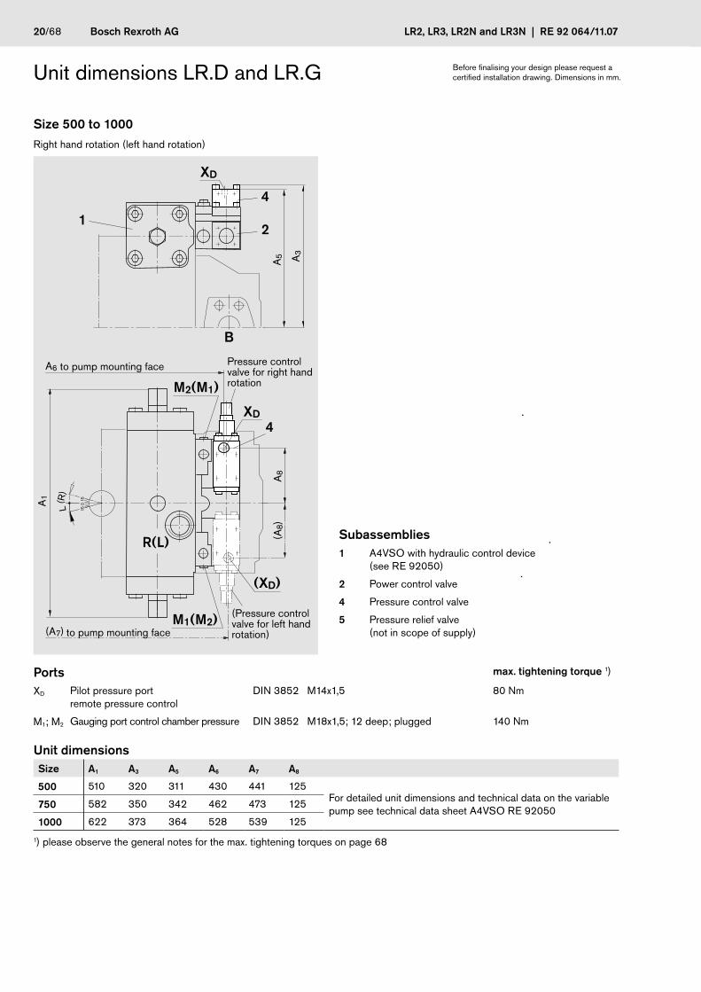
Unit dimensions LR.D and LR.G
Size 40 and 71 Size 125 to 355Right hand rotation (left hand) Right hand rotation (left hand)
2 4
B
1
R(L) XD
XD
L(R
)
1515
0A1
A7
(A8)
A2
(A2)
A5 A
3
A6
A4
Subassemblies see page 18
Ports max. tightening torque 1)
XD Pilot pressure portremote pressure control
DIN 3852 M14x1,5; 12 deep; plugged at LR.D 80 Nm
M1; M2 Gauging port control chamber press. DIN 3852 M14x1,5; 12 deep; plugged (Size 125 a. 180)M18x1,5; 12 deep; plugged (Size 250 a 355)
80 Nm140 Nm
Unit dimensions Size A1 A2 A3 A4 A5 A6 A7 A8
40 260 132 148 295 130 269 37 7For detailed unit dimensions and technical data on the variable pump see technical data sheet A4VSO RE 92050
71 296 132 159 322 141 296 37 7
125/180 354 132 195 391 171 365 37 7
250/355 424 132 238 453 207 427 37 7
1) please observe the general notes for the max. tightening torques on page 68
to pump mounting face
to pump mounting face
R(L)
B
2 4
1
3
B
XD
XD
M1(M2)
M2(M1)
L(R
)
15
15
0 Einschraubloch M33
A2
(A2)
A7
(A8)
A1
A3
A5
A6
A4
to pump mounting face
(XD at left hand rotation)
to pump mounting face
(XD at left hand rotation)
(Valve mounting for left hand rotation)
Valve mounting for right hand rotation
(Valve mounting for left hand rotation)
Valve mounting for right hand rotation
Before finalising your design please request a certified installation drawing. Dimensions in mm.
20/68 Bosch Rexroth AG LR2, LR3, LR2N and LR3N | RE 92 064/11.07
Unit dimensions LR.D and LR.G
Size 500 to 1000Right hand rotation (left hand rotation)
R(L)
M2(M1)
M1(M2)
B
4
21
4
XD
XD
(XD)
A1
A6
L(R
)
15
15
0 Einschraubloch M33
A5
A8
(A8)
A3
(A7)
Ports max. tightening torque 1)
XD Pilot pressure portremote pressure control
DIN 3852 M14x1,5 80 Nm
M1; M2 Gauging port control chamber pressure DIN 3852 M18x1,5; 12 deep; plugged 140 Nm
Unit dimensions Size A1 A3 A5 A6 A7 A8
500 510 320 311 430 441 125For detailed unit dimensions and technical data on the variable pump see technical data sheet A4VSO RE 92050
750 582 350 342 462 473 125
1000 622 373 364 528 539 125
1) please observe the general notes for the max. tightening torques on page 68
to pump mounting face
Subassemblies1 A4VSO with hydraulic control device
(see RE 92050)
2 Power control valve
4 Pressure control valve
5 Pressure relief valve (not in scope of supply)to pump mounting face
Pressure control valve for right hand rotation
(Pressure control valve for left hand rotation)
Before finalising your design please request a certified installation drawing. Dimensions in mm.
RE 92 064/11.07 | LR2, LR3, LR2N and LR3N Bosch Rexroth AG 21/68
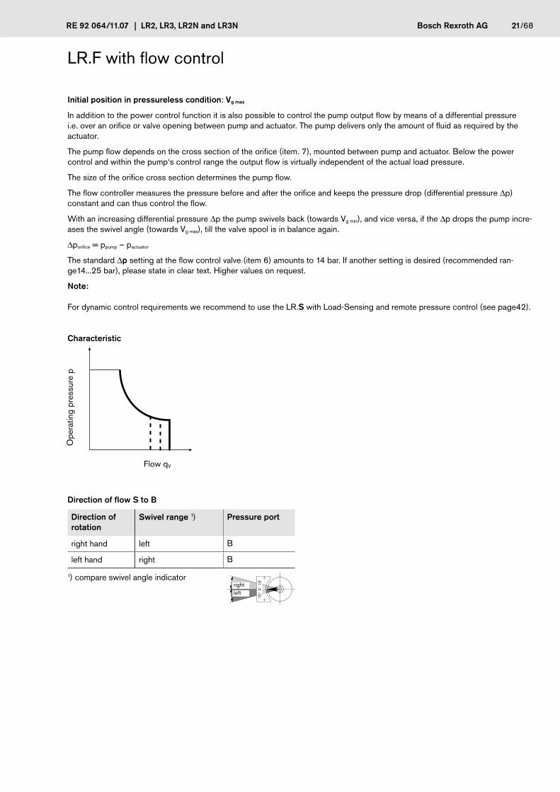
LR.F with flow control
Initial position in pressureless condition: Vg max
In addition to the power control function it is also possible to control the pump output flow by means of a differential pressure i.e. over an orifice or valve opening between pump and actuator. The pump delivers only the amount of fluid as required by the actuator.
The pump flow depends on the cross section of the orifice (item. 7), mounted between pump and actuator. Below the power control and within the pump‘s control range the output flow is virtually independent of the actual load pressure.
The size of the orifice cross section determines the pump flow.
The flow controller measures the pressure before and after the orifice and keeps the pressure drop (differential pressure Dp) constant and can thus control the flow.
With an increasing differential pressure Dp the pump swivels back (towards Vg min), and vice versa, if the Dp drops the pump incre-ases the swivel angle (towards Vg max), till the valve spool is in balance again.
Dporifice = ppump – pactuator
The standard Dp setting at the flow control valve (item 6) amounts to 14 bar. If another setting is desired (recommended ran-ge14...25 bar), please state in clear text. Higher values on request.
Note:
For dynamic control requirements we recommend to use the LR.S with Load-Sensing and remote pressure control (see page42).
Characteristic
Ope
ratin
g pr
essu
re p
Flow qV
Direction of flow S to B
Direction of rotation
Swivel range 1) Pressure port
right hand left B
left hand right B
1) compare swivel angle indicator
15°
0° 1
5°
rightleft

22/68 Bosch Rexroth AG LR2, LR3, LR2N and LR3N | RE 92 064/11.07
Schematics LR.F
Size 40 and 71 Size 125 to 355Example: A4VSO LR2F Example A4VSO LR2F
R(L)TU S MS K1 K2
MBB1
XF
1
2
6
7B
M2
MB
B
B1
1
3
2
6
XF
R(L)TU S MS K1M1 K2
7
PortsXF Pilot pressure port flow control
M1, M2 Gauging port control chamber pressure (Size 125 to 355)
Subassemblies1 A4VSO with hydraulic control device
(see RE 92050)
2 Power control valvel
3 Sandwich plate (Size 125 to 355)
6 Flow control valve
7 External orifice (not in scope of supply)
RE 92 064/11.07 | LR2, LR3, LR2N and LR3N Bosch Rexroth AG 23/68
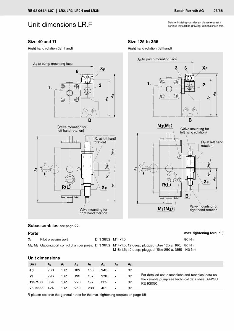
Unit dimensions LR.F
Size 40 and 71 Size 125 to 355Right hand rotation (left hand) Right hand rotation (lefthand)
2
6
B
1
R(L)
XF
XF
L(R
)
1515
0A1
A7
A2
(A2)
A5
(A8)
A3
A6
Subassemblies see page 22
Ports max. tightening torque 1)
XF Pilot pressure port DIN 3852 M14x1,5 80 Nm
M1; M2 Gauging port control chamber press. DIN 3852 M14x1,5; 12 deep; plugged (Size 125 a. 180)M18x1,5; 12 deep; plugged (Size 250 a. 355)
80 Nm140 Nm
Unit dimensions Size A1 A2 A3 A5 A6 A7 A8
40 260 132 182 156 243 7 37For detailed unit dimensions and technical data on the variable pump see technical data sheet A4VSO RE 92050
71 296 132 193 167 270 7 37
125/180 354 132 223 197 339 7 37
250/355 424 132 259 233 401 7 37
1) please observe the general notes for the max. tightening torques on page 68
(XF at left hand rotation)
Valve mounting for right hand rotation
(Valve mounting for left hand rotation)
to pump mounting face
Before finalising your design please request a certified installation drawing. Dimensions in mm.
6
M1(M2)
M2(M1)
R(L)
B
21
3
B
XF
XF
L(R
)
15
15
0 Einschraubloch M33
A1
A5 A
3
A6
A7
A2
(A8)
to pump mounting face
(XF at left hand rotation)
Valve mounting for right hand rotation
(Valve mounting for left hand rotation)
24/68 Bosch Rexroth AG LR2, LR3, LR2N and LR3N | RE 92 064/11.07
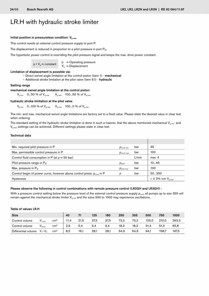
LR.H with hydraulic stroke limiter
Initial position in pressureless condition: Vg max
This control needs an external control pressure supply to port P.
The displacement is reduced in proportion to a pilot pressure in port PSt.
The hyperbolic power control is overriding the pilot pressure signal and keeps the max. drive power constant.
p • Vg = constantpVg
= Operating pressure= Displacement
Limitation of displacement is possible via: – Direct swivel angle limitation at the control piston (item 1) - mechanical – Additional stroke limitation at the pilot valve (item 6.1) - hydraulic
Setting range
mechanical swivel angle limitation at the control piston: Vg min 0...50 % of Vg max Vg max 100...50 % of Vg max
hydraulic stroke limitation at the pilot valve:
Vg min 0...100 % of Vg max Vg max 100...0 % of Vg max
The min. and max. mechanical swivel angle limitations are factory set to a fixed value. Please state the desired value in clear text when ordering.
The standard setting of the hydraulic stroke limitation is done in such a manner, that the above mentioned mechanical Vg min- and Vg max settings can be achieved. Different settings please state in clear text.
Technical data
Min. required pilot pressure in P pcontr min bar 35
Max. permissible control pressure in P pcontr max bar 100
Control fluid consumption in P (at p = 50 bar) L/min max. 4
Pilot pressure range in PSt ppilot bar 10...45
Max. pressure in PSt ppilot max bar 100
Control begin of power curve, however above control press. pcontr in P p bar 50...350
Hysteresis ≤ ± 2% von Vg max
Please observe the following in control combinations with remote pressure control (LR2GH and LR3GH) :
With a pressure control setting below the pressure level of the external control pressure supply pcontr all pumps up to size 355 will remain against the mechanical stroke limiter Vg min and the sizes 500 to 1000 may experience oscillations.
Table of values LR.H
Size 40 71 125 180 250 355 500 750 1000
Control volume V1max cm3 11,4 21,5 37,5 37,5 73,2 73,2 125,0 210,0 263,3
Control volume V2max cm3 2,9 5,4 9,4 9,4 18,3 18,3 31,4 51,3 65,8
Differential volume V1–V2 cm3 8,5 16,1 28,1 28,1 54,9 54,9 94,1 158,7 197,5

RE 92 064/11.07 | LR2, LR3, LR2N and LR3N Bosch Rexroth AG 25/68
LR.H with hydraulic stroke limiter
Characteristic
Vg min Vg max
Ope
ratin
g pr
essu
re p
Displacement
Direction of flow S to B
Direction of rotation
Swivel range 1) Pressure port
right hand left B
left hand right B
1) Compare swivel angle indicator
15°
0° 1
5°
rightleft
45
10
Vg / Vg max
Displacement
Pilo
t pre
ssur
e p S
t [ba
r]

26/68 Bosch Rexroth AG LR2, LR3, LR2N and LR3N | RE 92 064/11.07
Schematics LR.H
Size 40 and 71 Size 125 to 355Example: A4VSO LR2H Example A4VSO LR2H
R(L)TU S MS K1 K2
MBBB1
PSt
P
MSt
1
2
6.2
6.17.1
7.2
R(L)TU S MS K1M1 M2
MBBB1
PStP
MSt
7.2
1
6.2
2
6.1 7.1
3
K2
Size 500 to 1000Example: A4VSO LR2H
R(L)TU S MS K2K1
M2MBBB1 M1
P
PSt
6.1
7.2
1
2
Vgmin Vgmax
6.2
7.1
MSt
PortsP Control pressure port
PSt Pilot pressure port
MSt Gauging port pilot control pressure (plugged)
M1, M2 Gauging port control chamber pressure (Size 125 to 1000)
Subassemblies1 A4VSO with hydraulic control device
(see RE 92050)
2 Power control valve
3 Sandwich plate (Size 125 to 355)
6.1 Pilot valve-stroke limiter
6.2 Pressure control valve for stroke limiter
7.1 Check valve (for size 40 and 71 external, integrated in sizes 125 to 1000 )
7.2 Integrated check valve

RE 92 064/11.07 | LR2, LR3, LR2N and LR3N Bosch Rexroth AG 27/68
Unit dimensions LR.H
Size 40 and 71Right hand rotation (left hand)
2
6.1 7.1 6.2
B
1
R(L)
P
PSt
PSt
MSt
P
L(R
)
1515
0A1 A
10
A6
A2
(A2)
A8
A3
A7
A9
(A6)
A5A4
Ports max. tightening torque1)
P Control pressure port DIN 3853 S8 Form W 50 Nm
PSt Pilot pressure port DIN 3852 M14x1,5; 12 deep 80 Nm
MSt Gauging port pilot control pressure DIN 3853 S8 Form W plugged 50 Nm
Unit dimensions Size A1 A2 A3 A4 A5 A6 A7 A8 A9 A10
40 260 132 254 144 34 83 198 163 15 35 For detailed unit dimensions and technical data on the variable pump see technical data sheet A4VSO RE 9205071 296 132 268 166 39 83 215 178 15 35
1) please observe the general notes for the max. tightening torques on page 68
Valve mounting for left hand rotation item 2, 6.2 and 7.1 each rotated 180°
Subassemblies1 A4VSO with hydraulic control device
(see RE 92050)
2 Power control valve
6.1 Pilot valve-stroke limiter
6.2 Pressure control valve for stroke limiter
7.1 Check valveto pump mounting face
Before finalising your design please request a certified installation drawing. Dimensions in mm.
(P at left hand rotation)

28/68 Bosch Rexroth AG LR2, LR3, LR2N and LR3N | RE 92 064/11.07
Unit dimensions LR.H
Size 125 to 355Right hand rotation (left hand)
6.2
M1(M2)
M2(M1)
R(L)
B
2
1 7.1
3
B
P
PSt
MSt
6.1PSt
P
L(R
)
15
15
0 Einschraubloch M33
A10
A1
A7
A4 A5
A3
A8
A9
(A6)
A6
Ports max. tightening torque 1)
P Control pressure port DIN 3852 M18x1,5; 12 deep 140 Nm
PSt Pilot pressure port DIN 3852 M14x1,5; 12 deep 80 Nm
MSt Gauging port pilot control press. DIN 3853 S8 Form W closed 50 Nm
M1; M2 Gauging port control chamber press. DIN 3852 M14x1,5; 12 deep; plugged (Size 125 a. 180)M18x1,5; 12 deep; plugged (Size 250 a. 355)
80 Nm140 Nm
Unit dimensions Size A1 A3 A4 A5 A6 A7 A8 A9 A10
125/180 354 304 203 112 88 192 214 15 35 For detailed unit dimensions and technical data on the variable pump see technical data sheetA4VSO RE 92050250/355 424 352 248 129 88 228 261 15 35
1) please observe the general notes for the max. tightening torques on page 68
Valve mounting for left hand rotation item 2, 6.2 and 7.1 each rotated 180°
Subassemblies1 A4VSO with hydraulic control device
(see RE 92050)
2 Power control valve
3 Sandwich plate
6.1 Pilot valve-stroke limiter
6.2 Pressure control valve for stroke limiter
7.1 Integrated check valve in sandwich plateto pump mounting face
(P at left hand rotation)
Before finalising your design please request a certified installation drawing Dimensions in mm.

RE 92 064/11.07 | LR2, LR3, LR2N and LR3N Bosch Rexroth AG 29/68
Unit dimensions LR.H
Size 500 to 1000Right hand rotation (left hand)
2
6.2P
PSt
R(L)
M2(M1)
M1(M2)
P
B
1
MSt
PSt
6.1 7.2
A3
A1 A
6
A4 A5
A10
L(R
)
1515
0 Einschraubloch M33
A8
A7
(A6)
A9
Ports max. tightening torque 1)
P Control pressure port DIN 3852 M22x1,5; 14 deep 210 Nm
PSt Pilot pressure port DIN 3852 M14x1,5; 12 deep 80 Nm
MSt Gauging port pilot control pressure DIN 3853 S8 Form W closed 50 Nm
M1; M2 Gauging port control chamber pressure DIN 3852 M18x1,5; 12 deep; plugged 140 Nm
Unit dimensions Size A1 A3 A4 A5 A6 A7 A8 A9 A10
500 510 397 279 185 47 202 306 15 35 For detailed unit dimensions and technical data on the variable pump see technical data sheet A4VSO RE 92050
750 582 435 301 196 47 232 345 15 35
1000 622 463 360 202 47 255 372 15 35
1) please observe the general notes for the max. tightening torques on page 68
Subassemblies1 A4VSO with hydraulic control device
(see RE 92050)
2 Power control valve
6.1 Pilot valve-stroke limiter
6.2 Pressure control valve for stroke limiter
7.2 Integrated check valve in item 2to pump mounting face
Before finalising your design please request a certified installation drawing. Dimensions in mm.
(P at left hand rotation)
(Valve mounting item 2 and 6.2 for left hand rotation)
Valve mounting item 2 and 6.2 for right hand rotation

30/68 Bosch Rexroth AG LR2, LR3, LR2N and LR3N | RE 92 064/11.07
LR.M with mechanical stroke limiter Vg max
Initial position in pressureless condition: Vg max
In addition to the power control function it is also possible to limit the max. displacement Vg max steplessly through adjustment of a screw spindle. The setting must be done in a pressureless condition.
Adjustment data of stroke limiter Vg max
Setting range: 100% Vg max ...0% Vg max
(can go up to 104% of nominal displacement value)
Standard setting: Nominal-Vg max
Size 40 71 125 180 250 355
Vg-change/revolution cm3 4,3 6,3 9,1 13,1 14,4 20,6
Total adjustment stroke s mm 14,2 17,1 20,7 20,7 25,9 25,9
Right hand rotation (with view on screw spindle)–increase of displacement
Left hand rotation (with view on screw spindle)–decrease of displacement
Characteristic
Vg min Vg max
Ope
ratin
g pr
essu
re p
Displacement
Direction of flow S to B
Pump direction of rotation
Swivel range 1) Pressure port
right hand left B
left hand right B
1) Compare swivel angle indicator
15°
0° 1
5°
rightleft

RE 92 064/11.07 | LR2, LR3, LR2N and LR3N Bosch Rexroth AG 31/68
Schematics LR.M
Size 40 and 71 Size 125 to 355Example: A4VSO LR2M Example: A4VSO LR2M
R(L)TU S MS K1 K2
1
MBBB1
2
8
RKV
R(L)TU S MS K1M1 M2K2
MBBB1
RKV
1
2
3
8
PortsRkV External control fluid return
M1, M2 Gauging port control chamber pressure (Size 125 to 355)
Subassemblies1 A4VSO with hydraulic control device
(see RE 92050)
2 Power control valve
3 Sandwich plate (Size 125 to 355)
8 mechanical stroke limiter Vg max

32/68 Bosch Rexroth AG LR2, LR3, LR2N and LR3N | RE 92 064/11.07
Unit dimensions LR.M
Size 40 and 71Example: left hand rotation
2
B
1
R(L)
RkV
R 15
0
A2
A4
A3
A5
A1
8
Mechanical stroke limiter Vg max
Key AS 5x5x12 DIN 6885
For right hand rotation the Vg max - mechanical stroke limiter and Vg min - swivel angle limitation exchanged positions,see presentation size125 to 355 page 33.
Subassemblies see page 31
Ports max. tightening torque 1)
RkV External control fluid return DIN 3852 M18x1,5; 12 deep; plugged 140 Nm
Unit dimensions Size A1 A2 A3 A4 A5
40 130 132 148 144 172For detailed unit dimensions and technical data on the variable pump see technical data sheet A4VSO RE 9205071 148 132 159 166 188
1) please observe the general notes for the max. tightening torques on page 68
Swivel angle limitation Vg min
18
123
ø16f7
5 h9
18
M6; 12 deep
to pump mounting face
Before finalising your design please request a certified installation drawing Dimensions in mm.

RE 92 064/11.07 | LR2, LR3, LR2N and LR3N Bosch Rexroth AG 33/68
Unit dimensions LR.M
Size 125 to 355Example: right hand rotation
A4
M1
M2
R(L)
B
2
1
3
B
RkV
8
L 15 0
Einschraubloch M33
A2
A1
A5
A3
Mechanical stroke limiter Vg max
Key AS 5x5x12 DIN 6885
For left hand rotation the Vg max - mechanical stroke limiter and Vg min - swivel angle limitation exchanged positions,see presentation size 40 and 71 page 32.
Subassemblies see page 31
Ports max. tightening torque 1)
RkV External control fluid return DIN 3852 M18x1,5; 12 deep; plugged 140 Nm
M1; M2 Gauging port control chamber press. DIN 3852 M14x1,5; 12 deep; plugged (Size 125 a. 180)M18x1,5; 12 deep; plugged (Size 250 a. 355)
80 Nm140 Nm
Unit dimensions Size A1 A2 A3 A4 A5
125/180 177 132 195 203 213 For detailed unit dimensions and technical data on the variable pump see technical data sheet A4VSO RE 92050250/355 212 132 238 248 243
1) please observe the general notes for the max. tightening torques on page 68
18
123
ø16f7
5 h9
18
M6; 12 deep
to pump mounting face
Before finalising your design please request a certified installation drawing. Dimensions in mm.
Swivel angle limitation Vg min

34/68 Bosch Rexroth AG LR2, LR3, LR2N and LR3N | RE 92 064/11.07
LR.Z Hydraulic two-point control can be used as easy start option, external pilot pressure required
Initial position in pressureless condition and with RkV port unloaded: Vgmax
The LR2(3)Z is a simple 2-point displacement adjustment with overriding power control.
Pressurizing port Rkv brings the control device towards the adjustable Vgmin-stop. Unloading the port Rkv to tank enables the pump to perform the LR2(3)-control functions.
For the power and pressure pressure control functions port Rkv must be unloaded to tank (by customer).
This feature enables a pump to be started against a reduced starting torque.
Recommended pilot pressure at port Rkv:
pp =Output press. pHD
however at least 20 bar.2
The Vg min-stop will be factory set (between 0...50% Vg max). Please state desired value in clear text when ordering.
For prolonged periods in standby we recommend to use LR.G with external unloading of pilot pressure.
Direction of flow S to B
Pump direction of rotation
Swivel range 1) Pressure port
right hand left B
left hand right B
1) Compare swivel angle indicator
15°
0° 1
5°
rightleft

RE 92 064/11.07 | LR2, LR3, LR2N and LR3N Bosch Rexroth AG 35/68
Schematics LR.Z
Size 40 and 71 Size 125 to 355
Example: A4VSO LR2Z Example: A4VSO LR2Z
as easy start option with external pilot pressure supply as easy start option with external pilot pressure supply
1
R(L)TU S MS K1 K2
MBBB1
6
2
RkV
RkV
R(L)TU S MS K1M1 M2K2
MBBB1
RkV
3
1
2
Size 125 to 355 Size 500 to 1000Example: A4VSO LR2DZ Example: A4VSO LR2Z
with adapter plate RkV with pressure control as easy start option with external pilot pressure supply
R(L)TU S MS K1M1 M2K2
MBBB1
RkV
1
2
6
3
1
R(L)TU S MS K2K1
M2MBBB1
M1P
2
RkV
PortsRkV External control fluid return
M1, M2 Gauging port control chamber pressure (Size 125 to 1000)
P Control pressure port (Size 500 to 1000)
Subassemblies1 A4VSO with hydraulic control device
(see RE 92050)
2 Power control valve
3 Sandwich plate (Size 125 to 355)
6 Adapter plate RkV for LR.DZ and LR.GZ(Size 40 to 355)
for LR.DZand LR.GZ not in scope of
supply
not in scope of supply
not in scope of supply

36/68 Bosch Rexroth AG LR2, LR3, LR2N and LR3N | RE 92 064/11.07
Unit dimension LR.Z
Size 40 and 71Right hand rotation (left hand)
A4
(A4)
1
R(L)
6
RkV
B
RkV RkV
RkV
2
L(R
)
1515
0
A2
A5
A6
A3
A1
A9 A
10
A8
A7
(A7)
Subassemblies see page 35
Ports max. tightening torque 1)
RkV External control fluid return DIN 3852 M18x1,5; 12 deep 140 Nm
Unit dimensions Size A1 A2 A3 A4 A5 A6 A7 A8 A9 A10
40 260 132 149 80 209 114 63 219 152 168 For detailed unit dimensions and technical data on the variable pump see technical data sheet A4VSO RE 9205071 296 132 159 80 236 125 63 246 163 184
1) please observe the general notes for the max. tightening torques on page 68
LR.Z LR.DZ and LR.GZ
Power control valve mounting for right hand rotation
(Power control valve mounting for left hand rotation)
to pump mounting face
Before finalising your design please request a certified installation drawing. Dimensions in mm.
(RkV on left hand rotation)

RE 92 064/11.07 | LR2, LR3, LR2N and LR3N Bosch Rexroth AG 37/68
Unit dimension LR.Z
Size 125 to 355Right hand rotation (left hand)
A3
L(R
)
15
15
0 Einschraubloch M33
2
A7
(A7)
A4
(A4)
A9 A
10
RkV RkV
A6
1
3
M1(M2)
M2(M1)
R(L)
RkV
B
B
RkV
6
A1
A5
A8
Subassemblies see page 35
Ports max. tightening torque 1)
RkV External control fluid return DIN 3852 M18x1,5; 12 deep 140 Nm
M1; M2 Gauging port control chamber press. DIN 3852 M14x1,5; 12 deep; plugged (Size 125 a. 180)M18x1,5; 12 deep; plugged (Size 250 a. 355)
80 Nm140 Nm
Unit dimensions Size A1 A3 A4 A5 A6 A7 A8 A9 A10
125/180 354 195 80 305 155 63 315 193 209 For detailed unit dimensions and technical data on the variable pump see technical data sheet A4VSO RE 92050250/355 424 238 80 367 191 63 377 229 250
1) please observe the general notes for the max. tightening torques on page 68
LR.Z LR.DZ and LR.GZ
to pump mounting face
Before finalising your design please request a certified installation drawing. Dimensions in mm..
(RkV on left hand rotation)

38/68 Bosch Rexroth AG LR2, LR3, LR2N and LR3N | RE 92 064/11.07
Unit dimensions LR.Z
Size 500 to 1000Right hand rotation (left hand)
2
RkV
6R(L)
M2(M1)
M1(M2)
P
B
RkV
1
A3
A1
A6
A5
A4
L(R
)
1515
0 Einschraubloch M33
(A4)
Subassemblies see page 35
Ports max. tightening torque 1)
RkV External control fluid return DIN 3852 M18x1,5; 12 deep 140 Nm
M1; M2 Gauging port control chamber press.DIN 3852 M18x1,5; 12 deep; plugged 140 Nm
Unit dimensions Size A1 A3 A4 A5 A6
500 510 285 94 433 277For detailed unit dimensions and technical data on the variable pump see technical dat sheet A4VSO RE 92050
750 582 322 94 465 307
1000 622 350 94 532 330
1) please observe the general notes for the max. tightening torques on page 68
Power control valve mounting for right hand rotation
(Power control valve mounting for left hand rotation)
Before finalising your design please request a certified installation drawing. Dimensions in mm.
(RkV on left hand rotation)

RE 92 064/11.07 | LR2, LR3, LR2N and LR3N Bosch Rexroth AG 39/68
LR.Y Electric two-point control with internal supply of pilot pressure
Initial position in pressureless condition and solenoid energized: Vgmax
The LR2(3)Y is an electric two-position displacement adjustment with overriding power control and internal pilot pressure supply, i.e. the necessary pilot pressure is taken out of the pump pressure side.
Valve function:
a) Solenoid de-energized = easy start, pump swivels back towards Vgmin -stop as soon as an operating pressure of approx. 4...10 bar is reachedb) Solenoid energized = pump operates in power control mode
Direction of flow S to B
Pump direction of rotation
Swivel range 1) Pressure port
right hand left B
left hand right B
1) Compare swivel angle indicator
15°
0° 1
5°
rightleft

40/68 Bosch Rexroth AG LR2, LR3, LR2N and LR3N | RE 92 064/11.07
Schematics LR.Y
Size 40 and 71 Size 125 to 355 Example: A4VSO LR2Y Example: A4VSO LR2Y
MBBB1
1
R(L)TU S MS K1 K2
7
2
6
R(L)TU S MS K1M1 M2K2
1
2
3
67
MBBB1
PortsM1, M2 Gauging port control chamber pressure (size 125 to 355)
Subassemblies1 A4VSO with hydraulic control device (see RE 92050)
2 Power control valve
3 Sandwich plate (size 125 to 355)
6 3/2-directional poppet valve see RE 22058 (for size 40 to 355)
Type Solenoid
M-3SEW6U3X/420MG24N9K4 Solenoid with junction box (Hirschmann) to DIN EN 175 301-803 cable joint M16x1,5 for cable dia. 4,5...10 mmprotection IP65
7 sandwich plate
shown in energized position
shown in energized position
RE 92 064/11.07 | LR2, LR3, LR2N and LR3N Bosch Rexroth AG 41/68
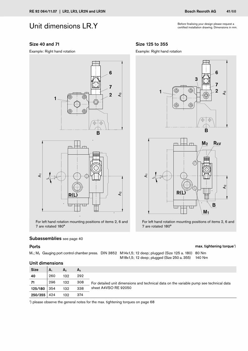
Unit dimensions LR.Y
Size 40 and 71 Size 125 to 355Example: Right hand rotation Example: Right hand rotation
B
1
R(L)
2
7
6
L 150
A2
A3
A1
M1
M2
R(L)
B
27
6
1
3
B
RkV
L 15
0 Einschraubloch M33
A2
A1
A3
For left hand rotation mounting positions of items 2, 6 and 7 are rotated 180°
For left hand rotation mounting positions of items 2, 6 and 7 are rotated 180°
Subassemblies see page 40
Ports max. tightening torque1)
M1; M2 Gauging port control chamber press. DIN 3852 M14x1,5; 12 deep; plugged (Size 125 a. 180)M18x1,5; 12 deep; plugged (Size 250 a. 355)
80 Nm140 Nm
Unit dimensions Size A1 A2 A3
40 260 132 292
For detailed unit dimensions and technical data on the variable pump see technical data sheet A4VSO RE 92050
71 296 132 308
125/180 354 132 338
250/355 424 132 374
1) please observe the general notes for the max. tightening torques on page 68
Before finalising your design please request a certified installation drawing. Dimensions in mm.
42/68 Bosch Rexroth AG LR2, LR3, LR2N and LR3N | RE 92 064/11.07
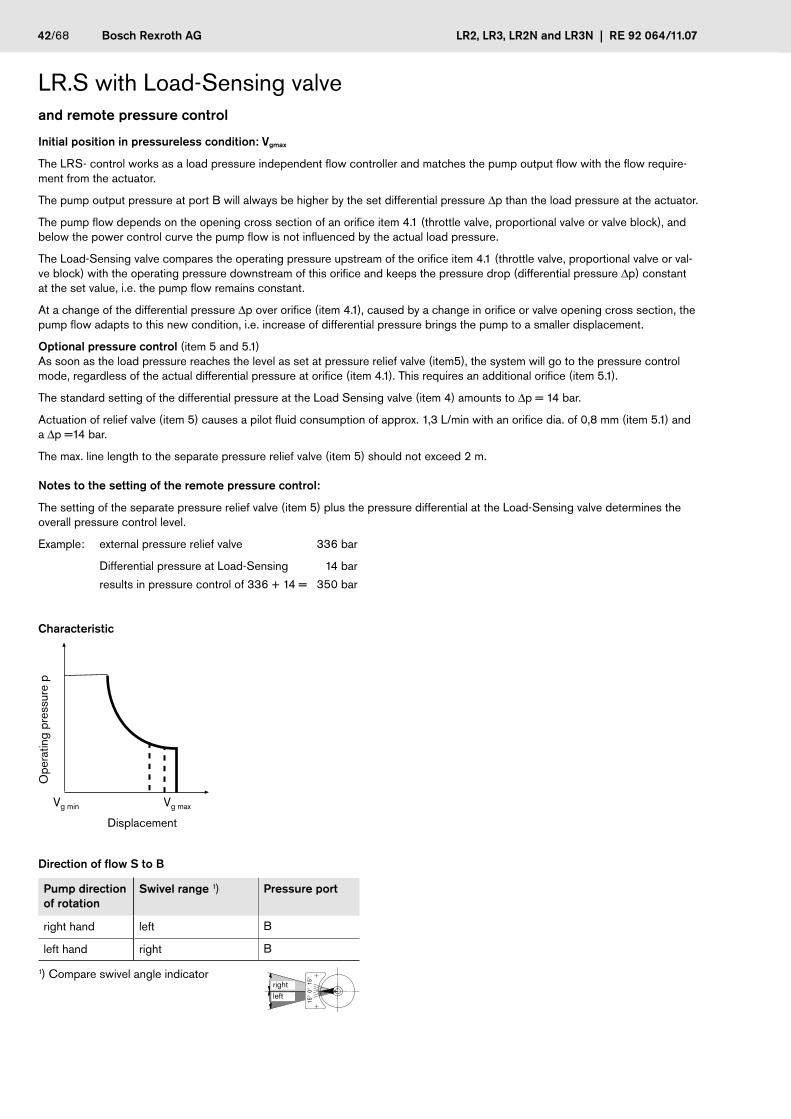
LR.S with Load-Sensing valve and remote pressure control
Initial position in pressureless condition: Vgmax
The LRS- control works as a load pressure independent flow controller and matches the pump output flow with the flow require-ment from the actuator.
The pump output pressure at port B will always be higher by the set differential pressure Dp than the load pressure at the actuator.
The pump flow depends on the opening cross section of an orifice item 4.1 (throttle valve, proportional valve or valve block), and below the power control curve the pump flow is not influenced by the actual load pressure.
The Load-Sensing valve compares the operating pressure upstream of the orifice item 4.1 (throttle valve, proportional valve or val-ve block) with the operating pressure downstream of this orifice and keeps the pressure drop (differential pressure Dp) constant at the set value, i.e. the pump flow remains constant.
At a change of the differential pressure Dp over orifice (item 4.1), caused by a change in orifice or valve opening cross section, the pump flow adapts to this new condition, i.e. increase of differential pressure brings the pump to a smaller displacement.
Optional pressure control (item 5 and 5.1)As soon as the load pressure reaches the level as set at pressure relief valve (item5), the system will go to the pressure control mode, regardless of the actual differential pressure at orifice (item 4.1). This requires an additional orifice (item 5.1).
The standard setting of the differential pressure at the Load Sensing valve (item 4) amounts to Dp = 14 bar.
Actuation of relief valve (item 5) causes a pilot fluid consumption of approx. 1,3 L/min with an orifice dia. of 0,8 mm (item 5.1) and a Dp =14 bar.
The max. line length to the separate pressure relief valve (item 5) should not exceed 2 m.
Notes to the setting of the remote pressure control:
The setting of the separate pressure relief valve (item 5) plus the pressure differential at the Load-Sensing valve determines the overall pressure control level.
Example: external pressure relief valve 336 bar
Differential pressure at Load-Sensing 14 bar
results in pressure control of 336 + 14 = 350 bar
Characteristic
Vg min Vg max
Ope
ratin
g pr
essu
re p
Displacement
Direction of flow S to B
Pump direction of rotation
Swivel range 1) Pressure port
right hand left B
left hand right B
1) Compare swivel angle indicator
15°
0° 1
5°
rightleft

RE 92 064/11.07 | LR2, LR3, LR2N and LR3N Bosch Rexroth AG 43/68
Schematics LR.S
Size 40 and 71 Size 125 to 355Example: A4VSO LR2S Example: A4VSO LR2S
R(L)TS MS
MBB1 B
1
4
2
X
5
4.1
5.1
U K1 K2
R(L)TS MS K1 K2M1 M2
MBB1
X
B
1
4
2
3
55.1
4.1
U
PortsX Pilot pressure control
M1, M2 Gauging port control chamber pressure (Size 125 to 355)
Subassemblies1 A4VSO with hydraulic control device
(see RE 92050)
2 Power control valve
3 Sandwich plate (Size 125 to 355)
4 Load-Sensing valve
4.1 Orifice for load sensing (not in scope of supply)
5 Pressure relief valve optional (not in scope of supply)
Recommended:DBD 6 (hydraulic) to RE 25402 or DBETR-SO 437 (electric) to RE 29166
5.1 Orifice for remote pressure control optional(not in scope of supply)Recommended: 0,8 - 1mmdepending on the load sensing control the pressure increase can amount to 14 bar
44/68 Bosch Rexroth AG LR2, LR3, LR2N and LR3N | RE 92 064/11.07
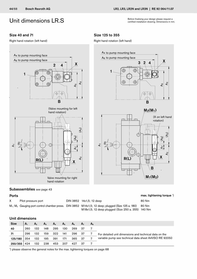
Unit dimensions LR.S
Size 40 and 71 Size 125 to 355Right hand rotation (left hand) Right hand rotation (left hand)
2 4
B
1
R(L) X
X
L(R
)
1515
0A1
A7
(A8)
A2
(A2)
A5 A
3
A6
A4
M1(M2)
M2(M1)
R(L)
B
2 4
1
3
B
X
X
L(R
)
15
15
0 Einschraubloch M33
A2
(A2)
A7
(A8)
A1
A3
A5
A6
A4
Subassemblies see page 43
Ports max. tightening torque 1)
X Pilot pressure port DIN 3852 14x1,5; 12 deep 80 Nm
M1; M2 Gauging port control chamber press. DIN 3852 M14x1,5; 12 deep; plugged (Size 125 a. 180)M18x1,5; 12 deep plugged (Size 250 a. 355)
80 Nm140 Nm
Unit dimensions Size A1 A2 A3 A4 A5 A6 A7 A8
40 260 132 148 295 130 269 37 7
For detailed unit dimensions and technical data on the variable pump see technical data sheet A4VSO RE 92050
71 296 132 159 322 141 296 37 7
125/180 354 132 195 391 171 365 37 7
250/355 424 132 238 453 207 427 37 7
1) please observe the general notes for the max. tightening torques on page 68
to pump mounting face
to pump mounting face
to pump mounting face
to pump mounting face
Valve mounting for right hand rotation
(Valve mounting for left hand rotation)
(X on left hand rotation)
Before finalising your design please request a certified installation drawing. Dimensions in mm.

RE 92 064/11.07 | LR2, LR3, LR2N and LR3N Bosch Rexroth AG 45/68
LR.N Hydraulic stroke control, pilot pressure dependent
Initial position in pressureless condition: Vg min
The hydraulic stroke control needs an external control pressure supply to port P
The displacement is increased proportional to an external pilot pressure signal in port PSt.
The hyperbolic power control is overriding the pilot pressure signal and will keep the pre-determined drive power constant.
p • Vg = constantpVg
= Operating pressure= Displacement
Limitation of displacement is possible via: – Direct swivel angle limitation at the control piston (item 1) - mechanical – Additional stroke limitation at the pilot valve (item 6.1) - hydraulic
Setting range
mechanical swivel angle limitation at the control piston: Vg min 0...50 % of Vg max Vg max 100...50 % of Vg max
hydraulic stroke limitation at the pilot valve:
Vg min 0...100 % of Vg max Vg max 100...0 % of Vg max
The min. and max. mechanical swivel angle limitations are factory set to a fixed value. Please state the desired value in clear text when ordering.
The standard setting of the hydraulic stroke limitation is done in such a manner, that the above mentioned mechanical Vg min- and Vg max settings can be achieved. Different settings please state in clear text.
Technical data
Min. required control pressure in P pcontr min bar 35
Min. required control pressure in P with boosted inlet S of max. 20 bar pcontr min bar 50
Max. permissible control pressure in P pcontr max bar 100
Control fluid consumption in P (at p = 50 bar) L/min max. 4
Pilot pressure range ppilot bar 10...45
Beginning of power control curve, however must be above control press. pcontr p bar 50...350
Hysteresis ≤ ± 2% von Vgmax
Please observe the following in control combinations with remote pressure control (LR2GN and LR3GN):
With a pressure control setting below the pressure level of the external control pressure supply pcontr in P all pumps up to size 355 will remain against the mechanical stroke limiter Vg min and the sizes 500 to 1000 may experience oscillations.
Table of values LR.N
Size 40 71 125 180 250 355 500 750 1000
Control volume V1max cm3 11,4 21,5 37,5 37,5 73,2 73,2 125,0 210,0 263,3
Control volume V2max cm3 2,9 5,4 12,7 12,7 24,9 24,9 40,1 72,6 88,0
Differential volume V1–V2 cm3 8,5 16,1 24,8 24,8 48,3 48,3 84,9 137,4 175,3
Control fluid required for de-stroking at
Control pressure pcontr = 50 bar; Operating pressur p < 50 bar; Beginnig of power control p > 50 bar
L/min 5,16* 6,44* 7,44* 7,44* 9,66* 9,66* 10,13* 11,00* 10,50*
at de-stroking time s 0,10 0,15 0,20 0,20 0,30 0,30 0,50 0,75 1,00
* Note that the control pressure supply needs an additional 4 L/min flow to compensate for the flow losses in the pilot circuit

46/68 Bosch Rexroth AG LR2, LR3, LR2N and LR3N | RE 92 064/11.07
LR.Nhydraulicstrokecontrol,pilotpressuredependent
Initial position in pressureless condition: Vg min
Characteristics
Displacement
Vg min Vg max
Ope
ratin
gpr
essu
rep
DisplacementP
ilotp
ress
ure
p pilo
t[ba
r]
45
10
Vg /Vg max
Direction of flow S to B
Pump direction of rotation
Swivel range 1) Pressure port
righthand left B
lefthand right B
1)Compareswivelangleindicator
15°
0° 1
5°
rightleft

RE 92 064/11.07 | LR2, LR3, LR2N and LR3N Bosch Rexroth AG 47/68
Schematics LR.N
Size 40 and 71 Size 125 to 355Example: A4VSO LR2N Example: A4VSO LR2N
MBBB1
1
R(L)TU S MS K1 K2
PSt
MSt
P
6.1
7.1
7.2
2
6.2
R(L)TU S MS K1M1 M2K2
MBBB1
1
6.2
3
2
7.1
MSt
PSt
P6.1
7.2
Size 500 to 1000Example: A4VSO LR2N
7.1
R(L)TU S MS K2K1
M2M1P
MBBB1
PSt
6.2
7.2
1
2
MSt
6.1
MSt
PortsP Control pressure port
PSt Pilot pressure port
MSt Gauging port pilot control pressure (closed)
M1, M2 Gauging port control chamber press. (Size 125 to 1000)
Subassemblies1 Pump with hydraulic control device
A4VSO (see RE 92050)
2 Power control valve
3 Sandwich plate (Size 125 to 355)
6.1 Pilot valve
6.2 Control valve
7.1 Check valve (integrated in sizes 125 to 1000)
7.2 Integrated check valve
shown in actuated position, i.e. P is pressurized
shown in actuated position, i.e. P is pressurized
shown in actuated position, i.e. P is pres-surized

48/68 Bosch Rexroth AG LR2, LR3, LR2N and LR3N | RE 92 064/11.07
Unit dimensions LR.N
Size 40 and 71Right hand rotation (left hand)
2
6.1 7.1 6.2
B
1
R(L)
P
PSt
PSt
MSt
P
L(R
)
1515
0A1 A
10
A6
A2
(A2)
A8
A3
A7
A9
(A6)
A5A4
Ports max. tightening torque 1)
P Control pressure port DIN 3853 S8 Form W 50 Nm
PSt Pilot pressure port DIN 3852 M14x1,5; 12 deep 80 Nm
MSt Gauging port pilot control pressure DIN 3853 S8 Form W; closed 50 Nm
Unit dimensions Size A1 A2 A3 A4 A5 A6 A7 A8 A9 A10
40 260 132 248 144 34 83 198 163 15 35 For detailed unit dimensions and technical data on the variable pump see technical data sheet A4VSO RE 9205071 296 132 264 166 39 83 215 180 15 35
1) please observe the general notes for the max. tightening torques on page 68
to pump mounting face
Subassemblies1 A4VSO with hydraulic control device
(see RE 92050)
2 Power control valve
6.1 Pilot valve
6.2 Control valve
7.1 check valve
Valve mounting position for left hand rotation item 2, 6.2 and 7.1 rotated by 180°
(P on left hand rotation)
Before finalising your design please request a certified installation drawing. Dimensions in mm.

RE 92 064/11.07 | LR2, LR3, LR2N and LR3N Bosch Rexroth AG 49/68
Unit dimensions LR.N
Size 125 to 355Right hand rotation (left hand)
M2(M1)
R(L)
B
1
3P
PSt
P
MSt
6.1PSt
6.2
2
7.1
M1(M2)
B
L(R
)
15
15
0 Einschraubloch M33A10
A1
A7
A4 A5
A3
A8
A9
(A6)
A6
Ports max. tightening torque 1)
P Control pressure port DIN 3852 M18x1,5; 12 deep 140 Nm
PSt Pilot pressure port DIN 3852 M14x1,5; 12 deep 80 Nm
MSt Gauging port pilot control pressure DIN 3853 S8 Form W closed 50 Nm
M1; M2 Gauging port control chamber pressure DIN 3852 M14x1,5; 12 deep; plugged (Size 125 a. 180)M18x1,5; 12 deep; plugged (Size 250 a. 355)
80 Nm140 Nm
Unit dimensions Size A1 A3 A4 A5 A6 A7 A8 A9 A10
125/180 354 298 203 112 88 192 214 15 35 For detailed unit dimensions and technical data on the variable pump see technical data sheet A4VSO RE 92050250/355 424 346 248 129 88 228 261 15 35
1) please observe the general notes for the max. tightening torques on page 68
to pump mounting face
Subassemblies1 A4VSO with hydraulic control device
(see RE 92050)
2 Power control valve
6.1 Pilot valve
6.2 Pilot control valve
7.1 Integrated check valve in sandwich plate
Valve mounting position for left hand rotation item 2, 6.2 and 7.1 rotated by 180°
(P on left hand rotation)
Before finalising your design please request a certified installation drawing. Dimensions in mm.

50/68 Bosch Rexroth AG LR2, LR3, LR2N and LR3N | RE 92 064/11.07
Unit dimensions LR.N
Size 500 to 1000Right hand rotation (left hand)
R(L)
P
B
1
PSt
6.2
6.1PSt
2
P
7.2
M2(M1)
M1(M2) MSt
A3
A1 A
6
A4 A5
A10
L(R
)
1515
0 Einschraubloch M33
A8
A7
(A6)
A9
Ports max. tightening torque 1)
P Control pressure port DIN 3852 M22x1,5; 14 deep 210 Nm
PSt Pilot pressure port DIN 3852 M14x1,5; 12 deep 80 Nm
MSt Gauging port pilot control pressure DIN 3853 S8 Form W; closed 50 Nm
M1; M2 Gauging port control chamber pressure DIN 3852 M18x1,5; 12 deep; plugged 140 Nm
Unit dimensions Size A1 A3 A4 A5 A6 A7 A8 A9 A10
500 510 392 279 185 47 202 306 15 35 For detailed unit dimensions and technical data on the variable pump see technical data sheet A4VSO RE 92050
750 582 430 301 195 47 232 345 15 35
1000 622 456 360 203 47 255 372 15 35
1) please observe the general notes for the max. tightening torques on page 68
Subassemblies1 A4VSO with hydraulic control device
(see RE 92050)
2 Power control valve
6.1 Pilot valve
6.2 Pilot control valve
7.2 Integrated check valve in item 2
to pump mounting face
Before finalising your design please request a certified installation drawing. Dimensions in mm.
(P on left hand rota-tion)
(Valve mounting of item 2 and 6.2 for left hand rotation)
Valve mounting of item 2 and 6.2 for right hand rotation

RE 92 064/11.07 | LR2, LR3, LR2N and LR3N Bosch Rexroth AG 51/68
LR.NT with hydr. stroke control and electric control of pilot pressure
Initial position in pressureless condition: Vg min
Only available in right hand rotation.
This control needs an external control pressure supply to port P
The proportional relief valve DBEP6 (to RE 29164) supplies a pilot pressure signal to the pilot pressure chamber at PSt proportio-nal to the valve solenoid current.The solenoid current controls and limits the pilot pressure.
Control through an electric command value. Current control through pulse width modulation.
Analogue or digital amplifiers can be used to drive the solenoids eg. proportional amplifier VT 3000 with 170 Hz (see RE 29935). Please order separately.
For the selection of electronics and operating fluids, description of functions and emergency overrides and further technical data please observe RE 29164.
Technical data – electric
Operating voltage 24 V
Nominal solenoid current 700 mA
Control current
Beginning of control at Vg0 and 10 bar pilot pressure 300 mA
End of control at Vgmax and 45 bar pilot pressure 700 mA
Nominal resistance at 20°C (R20) 19,5 W
Max. duty cycle 100 % (S1)
Solenoid plug Solenoid with cable box (Hirschmann) DIN EN 175 301-803with cable junction M16x1,5 for cable dia. 4,5...10 mm
Protection to DIN/EN 60529 IP 65
Emergency override yes, siehe RE 29164
Coil operating temperature to 150 °C
Technical data – hydraulic
Control pressure (in P) pmin bar 50
pmax bar 100
Hysteresis ≤ ± 4 % of Vgmax
Repeatability ≤ 2% von Vgmax
When calculating the required flow in port P it is necessary to consider the pilot flow losses in the proportional valve (eg. 4 L/min. at p = 50 bar).

52/68 Bosch Rexroth AG LR2, LR3, LR2N and LR3N | RE 92 064/11.07
LR.NT hydr. stroke control and electric control of pilot pressure
Initial position in pressureless condition: Vg min
Characteristic
0
Vg
Vgmax [%]
700
500
400
600
25 50 75 100
300
20
10
4540
30
Pilo
t pre
ssur
e p p
ilot [
bar]
Am
pera
ge I
[mA
]
Displacement
only available in right hand rotation
Direction of flow S to B
Pump direction of rotation
Swivel range 1) Pressure port
right hand left B
1) Compare swivel angle indicator
15°
0° 1
5°
rightleft

RE 92 064/11.07 | LR2, LR3, LR2N and LR3N Bosch Rexroth AG 53/68
Schematics LR.NT
Size 40 and 71 Size 125 to 355Example: A4VSO LR2NT Example: A4VSO LR2NT
MBBB1
1
R(L)TU S MS K1 K2
PSt
MSt
6.1P
2
9
7.1
6.2
7.2
R(L)TU S MS K1M1 M2K2
MBBB1
1
6.2
6.1
3
2
MSt
PSt
P
7.1
9
7.2
PortsP Control pressure port
PSt Gauging port pilot pressure
Mst Gauging port pilot control pressure
M1, M2 Gauging port control chamber pressure (Size 125 to 355)
Subassemblies1 A4VSO with hydraulic control device (see RE 92050)
2 Power control valve
3 Sandwich plate (only on size 125 to 355)
6.1 Pilot valve
6.2 Pilot control valve (shown in actuated position, i.e. P is pressurized)
7.1 Sandwich plate for mounting of proportional valve with check valve
7.2 Check valve, integrated in item 1
9 Proportional-pressure relief valve
DBEP6 B06-1X/45AG24NZ4M-382 with meter-in orifice dia. 1,0 mm
Solenoid with cable box (Hirschmann) to DIN EN 175 301-803 protection class IP 65 cable junction box M16x1,5 for cable dia. 4,5...10 mm
Size 500 to 1000 see page 54

54/68 Bosch Rexroth AG LR2, LR3, LR2N and LR3N | RE 92 064/11.07
Schematics LR.NT
Size 500 to 1000Example: A4VSO LR2NT
R(L)TU S MS K2K1
M2
M1P
MBBB1
PSt
6.2
6.1
1
2
9.2
9.1
MSt
7.1
7.2
PortsP Control pressure port
PSt Gauging port pilot pressure
MSt Gauging port pilot control pressure
M1, M2 Gauging port control chamber pressure
Subassemblies1 A4VSO with hydraulic control device (see RE 92050)
2 Power control valve
6.1 Pilot valve
6.2 Pilot control valve (shown in actuated position i.e. P is pressurized)
7.1, 7.2 Check valve integrated in power control valve (item 2)
9.1 Proportional pressure relief valve
DBEP6 A06-1X/45AG24NZ4M-382 with meter-in orifice dia. 1,0 mm
Solenoid with cable box (Hirschmann) to DIN EN 175 301-803 protection class IP 65 cable junction box M16x1,5 for cable dia. 4,5...10 mm
9.2 Sandwich plate for mounting of proportional valve
Size 40 to 355 see page 53

RE 92 064/11.07 | LR2, LR3, LR2N and LR3N Bosch Rexroth AG 55/68
Unit dimensions LR.NT
Size 40 and 71Right hand rotation
A8
A4
B
1
R(L)
PSt
7.1
6.2
6.1P
2
MSt
P
9
L 150A1
A2
A10
A6
A3
A7
A9
A5
Ports max. tightening torque 1)
P Control pressure port DIN 3852 M18x1,5; 12 deep 140 Nm
PSt Gauging port pilot pressure DIN 3853 S8 Form W; closed 50 Nm
MSt Gauging port pilot control pressure DIN 3853 S8 Form W; closed 50 Nm
Unit dimensions Size A1 A2 A3 A4 A5 A6 A7 A8 A9 A10
40 260 132 248 144 297 173 256 151 219 88 For detailed unit dimensions and technical data on the variable pump see technical data sheet A4VSO RE 9205071 296 132 264 166 324 173 267 162 246 88
1) please observe the general notes for the max. tightening torques on page 68
to pump mounting face
to pump mounting face
to pump mounting face
Subassemblies see page 53
Before finalising your design please request a certified installation drawing. Dimensions in mm.

56/68 Bosch Rexroth AG LR2, LR3, LR2N and LR3N | RE 92 064/11.07
Unit dimensions LR.NT
Size 125 to 355Right hand rotation
PSt
MSt P
M1
M2
R(L)
B
2
1 7.1
6.23 P96.1
L 15 0
Einschraubloch M33
A1
A3
A8
A5
A9
A7
A10
A4
Ports max. tightening torque 1)
P Control pressure port DIN 3852 M18x1,5; 12 deep 140 Nm
PSt Gauging port pilot pressure DIN 3853 S8 Form W; closed 50 Nm
MSt Gauging port pilot control pressure DIN 3853 S8 Form W; closed 50 Nm
M1; M2 Gauging port control chamber press. DIN 3852 M14x1,5; 12 deep; plugged (Size125 a. 180)M18x1,5; 12 deep; plugged (Size 250 a. 355)
80 Nm140 Nm
Unit dimensions Size A1 A3 A4 A5 A7 A8 A9 A10
125/180 354 298 203 393 297 192 315 88For detailed unit dimensions and technical data on the variable pump see technical data sheet A4VSO RE 92050250/355 424 346 248 455 333 228 377 88
1) please observe the general notes for the max. tightening torques on page 68
to pump mounting face
to pump mounting face
to pump mounting face
Before finalising your design please request a certified installation drawing. Dimensions in mm.
Subassemblies see page 53
RE 92 064/11.07 | LR2, LR3, LR2N and LR3N Bosch Rexroth AG 57/68
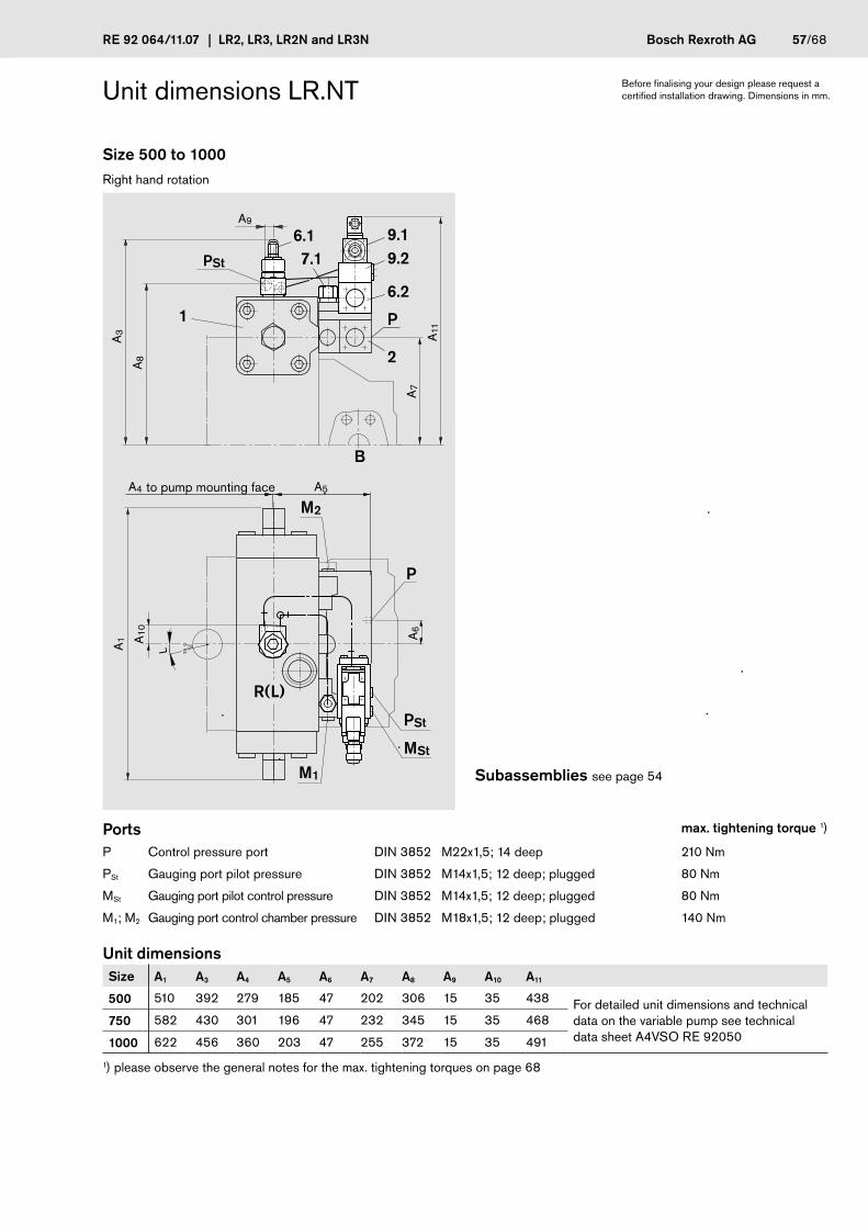
Unit dimensions LR.NT
Size 500 to 1000Right hand rotation
2
P
PSt
A9
R(L)
M2
M1
P
B
1
MSt
PSt
6.2
9.19.2
6.17.1
A3
A1 A
6
A4 A5
A10
L 150 Einschraubloch M33
A8
A7
A11
Ports max. tightening torque 1)
P Control pressure port DIN 3852 M22x1,5; 14 deep 210 Nm
PSt Gauging port pilot pressure DIN 3852 M14x1,5; 12 deep; plugged 80 Nm
MSt Gauging port pilot control pressure DIN 3852 M14x1,5; 12 deep; plugged 80 Nm
M1; M2 Gauging port control chamber pressure DIN 3852 M18x1,5; 12 deep; plugged 140 Nm
Unit dimensions Size A1 A3 A4 A5 A6 A7 A8 A9 A10 A11
500 510 392 279 185 47 202 306 15 35 438 For detailed unit dimensions and technical data on the variable pump see technical data sheet A4VSO RE 92050
750 582 430 301 196 47 232 345 15 35 468
1000 622 456 360 203 47 255 372 15 35 491
1) please observe the general notes for the max. tightening torques on page 68
to pump mounting face
Before finalising your design please request a certified installation drawing. Dimensions in mm.
Subassemblies see page 54

58/68 Bosch Rexroth AG LR2, LR3, LR2N and LR3N | RE 92 064/11.07
Example of control combination LR2GN Hyperbolic power control with hydraulic stroke control and remote pressure control
Initial position in pressureless condition: Vg min
For a description and the technical data in each case see:
– hyperbolic power control LR2 see page 4
– remote pressure control G see page 17
– hydraulic stroke control N see page 45
This control needs an external control pressure supply to port P.
With control combinations LR2GN and LR3GN please note the following:
With a pressure control setting below the pressure level of the external control pressure supply pcontr in P all pumps up to size 355 will remain against the mechanical stroke limiter Vg min and the sizes 500 to 1000 may experience oscillations.
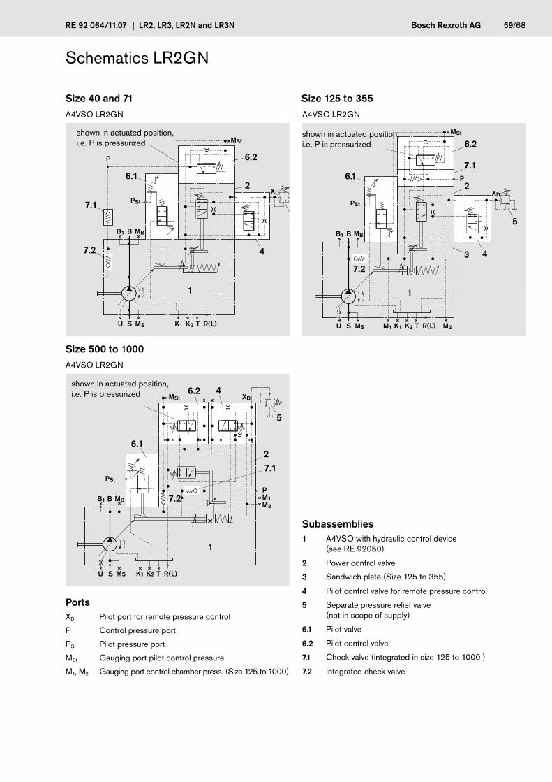
RE 92 064/11.07 | LR2, LR3, LR2N and LR3N Bosch Rexroth AG 59/68
Schematics LR2GN
Size 40 and 71 Size 125 to 355A4VSO LR2GN A4VSO LR2GN
MBBB1
1
R(L)TU S MS K1 K2
PSt
MSt
P
6.1
XD
5
4
2
6.2
7.1
7.2
R(L)TU S MS K1M1 M2K2
MBBB1
1
3
MSt
PSt
P
XD
6.2
2
5
4
7.2
7.16.1
Size 500 to 1000A4VSO LR2GN
R(L)TU S MS K2K1
M2
M1P
MBBB1
PSt
6.2
6.1
7.2
1
2
MSt XD4
5
7.1
PortsXD Pilot port for remote pressure control
P Control pressure port
PSt Pilot pressure port
MSt Gauging port pilot control pressure
M1, M2 Gauging port control chamber press. (Size 125 to 1000)
shown in actuated position, i.e. P is pressurized
shown in actuated position, i.e. P is pressurized
Subassemblies1 A4VSO with hydraulic control device
(see RE 92050)
2 Power control valve
3 Sandwich plate (Size 125 to 355)
4 Pilot control valve for remote pressure control
5 Separate pressure relief valve (not in scope of supply)
6.1 Pilot valve
6.2 Pilot control valve
7.1 Check valve (integrated in size 125 to 1000 )
7.2 Integrated check valve
shown in actuated position, i.e. P is pressurized

60/68 Bosch Rexroth AG LR2, LR3, LR2N and LR3N | RE 92 064/11.07
Unit dimensions LR2GN
Size 40 and 71Right hand rotation (left hand)
B
1
R(L)
P
PSt
PSt
MSt
XD
XD
4
6.1 7.1 6.2
2
P
L(R
)
1515
0A1
A7
(A8)
A14
A11
A2
(A2)
A9
A13
A3
A5
A12
A10
(A11
)
A6
A15
A4
Ports max. tightening torque 1)
XD Pilot pressure portfor remote pressure control
DIN 3852 M14x1,5; 12 deep 80 Nm
P Control pressure port DIN 3853 S8 Form W 50 Nm
PSt Pilot pressure port DIN 3852 M14x1,5; 12 deep 80 Nm
MSt Gauging port pilot control pressure DIN 3853 S8 Form W; closed 50 Nm
Unit dimensions Size A1 A2 A3 A4 A5 A6 A7 A8 A9 A10 A11 A12 A13 A14 A15
40 260 132 248 295 130 269 37 7 144 34 83 15 163 35 198 For detailed unit dimensions and technical data on the variable pump see technical data sheet A4VSO RE 9205071 296 132 258 322 146 296 37 7 166 39 83 15 180 35 215
1) please observe the general notes for the max. tightening torques on page 68
to pump mounting face
Subassemblies1 A4VSO with hydraulic control device
(see RE 92050)
2 Power control valve
4 Pilot control valve for remote pressure control
5 Separate pressure relief valve (not in scope of supply)
6.1 Pilot valve
6.2 Pilot control valve
7.1 Check valve
(XD on left hand rotation)
to pump mounting faceto pump mounting face
Valve mounting position for left hand rotation item 2, 4, 6.2 and 7.1 with piping rotated by 180°
Before finalising your design please request a certified installation drawing. Dimensions in mm.

RE 92 064/11.07 | LR2, LR3, LR2N and LR3N Bosch Rexroth AG 61/68
Unit dimensions LR2GN
Size 125 to 355Right hand rotation (left hand)
6.2
M1(M2)
M2(M1)
R(L)
B
2
1
4
3
B
P
PSt
PMSt
6.1PSt
XD
XD
7.1
L(R
)
15
15
0 Einschraubloch M33
A15
A1
A9 A10
A3
A13
A14
(A11
)A
11
A7
(A8)
A12
A5
A6
A4
Ports max. tightening torque 1)
XD Pilot port for remote pressure control
DIN 3852 M14x1,5; 12 deep 80 Nm
P Control pressure port DIN 3852 M18x1,5; 12 deep 140 Nm
PSt Pilot pressure port DIN 3852 M14x1,5; 12 deep 80 Nm
MSt Gauging port pilot control pressure DIN 3853 S8 Form W; closed 50 Nm
M1; M2 Gauging port control chamber press. DIN 3852 M14x1,5; 12 deep; plugged (Size 125 a. 180)M18x1,5; 12 deep; plugged (Size 250 a. 355)
80 Nm140 Nm
Unit dimensions Size A1 A3 A4 A5 A6 A7 A8 A9 A10 A11 A12 A13 A14 A15
125/180 354 299 391 171 365 37 7 203 112 88 192 214 15 35 For detailed unit dimensions and technical data on the variable pump see technical data sheet A4VSO RE 92050250/355 424 346 453 207 427 37 7 248 129 88 228 261 15 35
1) please observe the general notes for the max. tightening torques on page 68
to pump mounting faceto pump mounting face
to pump mounting face
Subassemblies1 A4VSO with hydraulic control device
(see RE 92050)
2 Power control valve
3 Sandwich plate
4 Pilot control valve for remote pressure control
5 Separate pressure relief valve (not in scope of supply)
6.1 Pilot valve
6.2 Pilot control valve
7.1 Integrated check valve
Valve mounting position for left hand rotation item 2, 6.2 and 7.1 rotated by 180°
Before finalising your design please request a certified installation drawing. Dimensions in mm.
(XD on left hand rotation)

62/68 Bosch Rexroth AG LR2, LR3, LR2N and LR3N | RE 92 064/11.07
Unit dimensions LR2GN
Size 500 to 1000Right hand rotation (left hand)
R(L)
M2(M1)
M1(M2)
P
XD
B
1
MSt
PSt
MSt
XD
6.2P
6.1PSt
4
6.2
2
7.1
A3
A1 A
11
A9 A10
A15
L(R
)
1515
0 Einschraubloch M33
A13
A12
A5
(A11
)A
8(A
8)
A14
A6
(A7)
Ports max. tightening torque 1)
XD Pilot pressure port forremote pressure control
DIN 3852 M14x1,5; 12 deep 80 Nm
P Control pressure port DIN 3852 M22x1,5; 14 deep 210 Nm
PSt Pilot pressure port DIN 3852 M14x1,5; 12 deep 80 Nm
MSt Gauging port pilot control pressure DIN 3853 S8 Form W; closed 50 Nm
M1; M2 Gauging port control chamber pressure DIN 3852 M18x1,5; 12 deep; plugged 140 Nm
Unit dimensions Size A1 A3 A5 A6 A7 A8 A9 A10 A11 A12 A13 A14 A15
500 510 392 311 430 441 125 279 186 47 202 306 15 35 For detailed unit dimensions and technical data on the variable pump see technical data sheet A4VSO RE 92050
750 582 430 342 462 473 125 301 195 47 232 345 15 35
1000 622 456 364 528 539 125 360 203 47 255 372 15 35
1) please observe the general notes for the max. tightening torques on page 68
to pump mounting face
to pump mounting face
Subassemblies1 A4VSO with hydraulic control device
(see RE 92050)
2 Power control valve
4 Pilot control valve for remote pressure control
5 Separate pressure relief valve (not in scope of supply)
6.1 Pilot valve
6.2 Pilot control valve
7.1 Integrated check valve
Valve mounting position for left hand rotation item 2, 4 and 6.2 rotated by 180° (mirror view around pump axis)
(XD on left hand rotation)
Before finalising your design please request a certified installation drawing. Dimensions in mm.
to pump mounting face

RE 92 064/11.07 | LR2, LR3, LR2N and LR3N Bosch Rexroth AG 63/68
Example of control combination LR2GNT Hyperbolic-power control with hydraulic stroke control, electric control of pilot pressure and remote pressure control
Initial position in pressureless condition: Vg min
Only available in right hand rotation.
For the description and technical data see previous pages:
– hyperbolic power control LR2 page 4
– remote pressure control G page 17
– hydraulic stroke control N page 45
– electric pilot pressure control T page 51
This control needs an external control pressure supply to port P.
With control combinations LR2GNT and LR3GNT please note the following:
With a pressure control setting below the pressure level of the external control pressure supply pcontr in P all pumps up to size 355 will remain against the mechanical stroke limiter Vg min and the sizes 500 to 1000 may experience oscillations.

64/68 Bosch Rexroth AG LR2, LR3, LR2N and LR3N | RE 92 064/11.07
Schematics LR2GNT
Size 125 to 355 Size 500 to 1000A4VSO LR2GNT, right hand rotation A4VSO LR2GNT, right hand rotation
7.2
R(L)TU S MS K1M1 M2K2
MBBB1
1
6.2
6.1
3
2
7.1
MSt
PSt
P
XD
9.1
54
R(L)TU S MS K2K1
M2M1P
MBBB1
PSt
46.1
1
2
MSt XD
9.19.2
56.2
7.2
7.1
PortsXD Pilot pressure port for remote pressure control
P Control pressure port
PSt Gauging port pilot pressure
M1, M2 Gauging port control chamber pressure
MSt Gauging port pilot control pressure
Subassemblies1 A4VSO with hydraulic control device (see RE 92050)
2 Power control valve
3 Sandwich plate (Size 125 to 355)
4 Pilot control valve for remote pressure control
5 Separate pressure relief valve (not in scope of supply)
6.1 Pilot valve
6.2 Pilot control valve
7.1 Sandwich plate for mounting of proportional valve with check valve (Size 125 to 355)Check valve, integrated in item 2 (Size 500 to 1000)
7.2 Check valve, integrated in item 1 (Size 125 to 355)Check valve, integrated in item 2 (Size 500 to 1000)
9.1 Proportional pressure relief valve
DBEP6 B06-1X/45AG24NZ4M-382 (Size 125 to 355) DBEP6 A06-1X/45AG24NZ4M-382 (Size 500 to 1000)with meter-in orifice dia. 1,0 mm
Solenoid with cable box(Hirschmann) to DIN EN 175 301-803 protection class IP 65 cable junction M16x1,5 for cable dia. 4,5...10 mm
9.2 Sandwich plate for mounting of proportional valve (Size 500 to 1000)
Size 40 and 71 available on request.
shown in actuated position i.e. P is pressurized
shown in actuated position i.e. P is pressurized

RE 92 064/11.07 | LR2, LR3, LR2N and LR3N Bosch Rexroth AG 65/68
Unit dimensions LR2GNT
Size 40 and 71 Size 125 to 355available on request Right hand rotation
P
PSt
MSt
M1
M2
R(L)
B
2
1
4
7.1
6.23 P9.1
6.1
XD
XD
L 15
0 Einschraubloch M33
A1
A3
A5
A6
A4
A12
A2
A11
A9 A10A
7
Subassemblies see page 64
Ports max. tightening torque 1)
XD Pilot pressure portremote pressure control
DIN 3852 M14x1,5; 12 deep 80 Nm
P Control pressure port DIN 3852 M18x1,5; 12 deep 140 Nm
PSt Gauging port pilot pressure DIN 3853 S8 Form W; closed 50 Nm
MSt Gauging port pilot control pressure DIN 3853 S8 Form W; closed 50 Nm
M1; M2 Gauging port control chamber press. DIN 3852 M14x1,5; 12 deep; plugged (Size 125 a. 180)M18x1,5; 12 deep; plugged (Size 250 a. 355)
80 Nm140 Nm
Unit dimensions Size A1 A2 A3 A4 A5 A6 A7 A8 A9 A10 A11 A12
125/180 354 297 194 393 171 365 37 7 203 112 88 192 For detailed unit dimensions and technical data on the variable pump see technical dat sheet A4VSO RE 92050250/355 424 333 346 455 207 427 37 7 248 129 88 228
1) please observe the general notes for the max. tightening torques on page 68
to pump mounting face
to pump mounting face
to pump mounting face
Before finalising your design please request a certified installation drawing. Dimensions in mm.

66/68 Bosch Rexroth AG LR2, LR3, LR2N and LR3N | RE 92 064/11.07
Unit dimensions LR2GNT
Size 500 to 1000Right hand rotation
2
P
R(L)
M2
M1
P
B
MSt
PSt
6.2
9.19.27.1
XD
4
9
1
6.1
A3
A1 A
11
A9 A10
A6
L 150
A12
A5
A8
A2
XD
Ports max. tightening torque 1)
XD Pilot pressure port forremote pressure control
DIN 3852 M14x1,5; 12 deep 80 Nm
P Control pressure port DIN 3852 M22x1,5; 14 deep 210 Nm
PSt Gauging port pilot pressure DIN 3852 M14x1,5; 12 deep; plugged 80 Nm
MSt Gauging port pilot control pressure DIN 3852 M14x1,5; 12 deep plugged 80 Nm
M1; M2 Gauging port control chamber pressure DIN 3852 M18x1,5; 12 deep; plugged 140 Nm
Unit dimensions Size A1 A2 A3 A5 A6 A7 A8 A9 A10 A11 A12
500 510 438 392 311 430 441 125 279 185 47 202For detailed unit dimensions and technical data on the variable pump see technical data sheet A4VSO RE 92050
750 582 468 430 342 462 473 125 301 196 47 232
1000 622 491 456 364 528 539 125 360 203 47 255
1) please observe the general notes for the max. tightening torques on page 68
to pump mounting face
to pump mounting face Subassemblies see page 64
Before finalising your design please request a certified installation drawing. Dimensions in mm.

RE 92 064/11.07 | LR2, LR3, LR2N and LR3N Bosch Rexroth AG 67/68
Installation notesFor mounting of pumps with control version LR.Y and LR.NT and combinations thereof inside the reservoir please consult us.

68/68 Bosch Rexroth AG LR2, LR3, LR2N and LR3N | RE 92 064/11.07
Bosch Rexroth AG HydraulicsProduct Segment Axial Piston UnitsPlant HorbAn den Kelterwiesen 14 72160 Horb, Germany Phone +49 (0) 74 51 92-0 Facsimile +49 (0) 74 51 82 [email protected] www.boschrexroth.com/axial-piston-pumps
© This document, as well as the data, specifications and other information set forth in it, are the exclusive property of Bosch Rexroth AG. It may not be reproduced or given to third parties without its consent.
The data specified above only serve to describe the product. No statements concerning a certain condition or suitability for a certain application can be derived from our information. The information given does not release the user from the obligation of own judgment and verification. It must be remembered that our products are subject to a natural process of wear and aging.
Subject to change.
General notes– The control devices LR2, LR3 and LR.N together with the pump A4VSO were designed for operation in open loop circuits.
– Systems design, installation and commissioning require trained technicians or tradesmen.
– All hydraulic ports and connections for control functions can only be used for the fastening of hydraulic lines.
– Tightening torques: The tightening torques mentioned in this data sheet are maximum values and must not be exceeded (Maximum values for thread). Manufacturers information concerning the maximum permitted tightening torques of the various fittings is to be observed! For DIN 13 mounting bolts, we recommend that tightening torques be checked on a case by case basis in accordance with VDI 2230 published 2003.
– During and shortly after operation of a pump the housing and especially the solenoids can be extremely hot, avoid being burned. Wear protective clothing.
– All data, information and instructions mentioned in this data sheet must be adhered to.