rc30x0f installation kit - research concepts · 2.5 inclinometer data sheet ... b-2.4 azimuth brake...
TRANSCRIPT
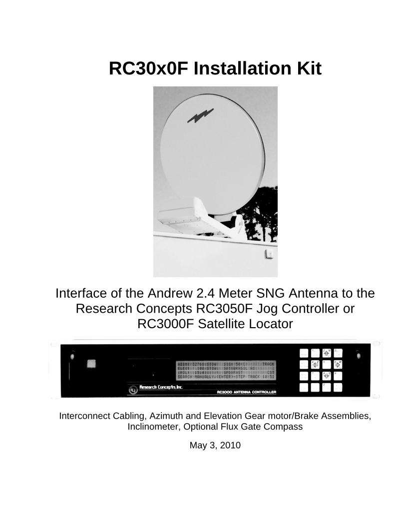
RC30x0F Installation Kit
Interface of the Andrew 2.4 Meter SNG Antenna to the
Research Concepts RC3050F Jog Controller or RC3000F Satellite Locator
Interconnect Cabling, Azimuth and Elevation Gear motor/Brake Assemblies,
Inclinometer, Optional Flux Gate Compass
May 3, 2010
RC30x0F Installation Kit Azimuth and Elevation Motor/Brake 2
RC30X0F INSTALLATION KIT .................................................................................................1
1.0 INTRODUCTION.................................................................................................................5
1.1 RC30x0F Kit .......................................................................................................................................................................5
2.0 INCLINOMETER ENCLOSURE..........................................................................................6
2.1 Inclinometer Installation....................................................................................................................................................6
THE FOLLOWING TABLE DOCUMENTS INCLINOMETER CONNECTIONS … ....................6 2.1.1 Inclinometer Enclosure Mounting Kit ...........................................................................................................................7
HERE ARE THE CONTENTS OF THAT KIT … ........................................................................7
2.2 Inclinometer Mounting Diagram ......................................................................................................................................8
2.4 Inclinometer Enclosure (RCI p/n FP-RC3KINCLAN2) Bill of Materials...................................................................12
2.5 Inclinometer Data Sheet...................................................................................................................................................13
3.0 FLUX GATE COMPASS ...............................................................................................14
3.1 Flux Gate Compass Installation ......................................................................................................................................14 3.1.1 Installation Overview..................................................................................................................................................14
THE FLUX GATE INSTALLATION PROCEDURE IS DETAILED IN THIS SECTION. ...........17 3.1.4 Drill Templates ...........................................................................................................................................................20
3.2 Flux Gate Assembly Bill of Materials .............................................................................................................................22 3.2.1 Pipe Strap Conduit Clamp Assembly..........................................................................................................................23
4.0 ANTENNA WIRING HARNESS........................................................................................24
4.1 Convoluted Tubing Installation.......................................................................................................................................24
HERE ARE THE CONTENTS OF THAT KIT … ......................................................................25
4.2 Polarization Motor Wiring Harness Installation and Limit Switch Modification......................................................25
POLARIZATION MOTOR........................................................................................................25 4.2.1 Photo of Polarization Motor Detailing Wiring Harness Installation ...........................................................................27
4.3 Wiring Harness Schematic Diagrams .............................................................................................................................28
4.4 Contact Arrangement for Wiring Harness Connectors ................................................................................................31
4.5 Connector and Cable Schedule for Wiring Harness......................................................................................................32
RC30x0F Installation Kit Azimuth and Elevation Motor/Brake 3 5.0 CONTROLLER SOFTWARE SETUP ...............................................................................33
5.1 Antenna Mount Characteristics ......................................................................................................................................33
5.2 RC3050F Software Setup .................................................................................................................................................34 5.2.1 Deactivate Software Limits.........................................................................................................................................34 5.2.2 Move Mount to the Azimuth Stow Position ...............................................................................................................34 5.2.3 Define Azimuth Stow (Reference) Position................................................................................................................34 5.2.4 Define Elevation Inclinometer Reference Position.....................................................................................................35 5.2.5 Define Elevation Resolver Reference Position ...........................................................................................................35 5.2.6 Determine Electronic Inclinometer Scale Factor ........................................................................................................36 5.2.7 Define Elevation Up Software Limit ..........................................................................................................................36 5.2.8 Define Elevation Down Software Limit .....................................................................................................................36 5.2.9 Define Elevation Sync Software Limit .......................................................................................................................37 5.2.10 Define Elevation STOW Software Limit ..................................................................................................................37 5.2.11 Define Polarization Reference Position ....................................................................................................................37 5.2.12 Confirm Operation of the Polarization CW and CCW Limit Switches ....................................................................37 5.2.13 Confirm Azimuth CW Limit Switch Operation........................................................................................................38 5.2.14 Confirm Azimuth CCW Limit Switch Operation .....................................................................................................38 5.2.15 Activate Software Limits ..........................................................................................................................................38 5.2.16 Confirm Software Limits ..........................................................................................................................................38
5.3 RC3000F Software Setup .................................................................................................................................................39
APPENDIX A INSTALLATION KIT HARDWARE ..................................................................43
A-1 RC30x0 Installation Kit Hardware Bill of Materials (RCI p/n FP-RC3KFHDKIT1) ..............................................43
APPENDIX B AZIMUTH AND ELEVATION MOTOR/BRAKE ...............................................45
B-1 Azimuth and Elevation Motor/Brake Installation ........................................................................................................45 B-1.1 Attaching the Motor/Brake Assemblies to the Gear Reducers...................................................................................45 B-1.2 Routing and Securing the Motor/Brake Cables to the Pedestal .................................................................................46 B.1.3 Azimuth and Elevation Motor/Brake Cable Routing Diagram ..................................................................................47 B-1.4 Azimuth Motor/Brake Installation Kit .......................................................................................................................48 B-1.5 Elevation Motor/Brake Installation Kit......................................................................................................................49
B-2 Azimuth and Elevation Motor/Brake Unit Assembly Procedures...............................................................................50 B-2.1 Azimuth Motor Drawing............................................................................................................................................55 B-2.2 Elevation Motor Drawing ..........................................................................................................................................56 B-2.3 Azimuth and Elevation Motor/Brake Detail ..............................................................................................................57 B-2.4 Azimuth Brake Cable Detail ......................................................................................................................................58 B-2.5 Elevation Brake Cable Detail.....................................................................................................................................59
B-3 Azimuth and Elevation Motor/Brake Unit Disassembly Procedures ..........................................................................60
B.4 Azimuth and Elevation Motor/Brake Unit Test Procedures ........................................................................................61
AZIMUTH/ELEVATION MOTOR/BRAKE TEST FIXTURE .....................................................61 B-4.1 Test Procedure ...........................................................................................................................................................62 2.4.2 Test the Azimuth Motor/Brake Assembly ..................................................................................................................62 B-4.3 Test the Elevation Motor/Brake Assembly ................................................................................................................63 B-4.4 Troubleshooting .........................................................................................................................................................63
B-5 Azimuth Motor/Brake Unit Bill of Materials ................................................................................................................65

RC30x0F Installation Kit Azimuth and Elevation Motor/Brake 4 BILL OF MATERIALS – RCI P/N FB-3KFAZMB1 ..................................................................65
B-6 Elevation Motor/Brake Unit Bill of Materials...............................................................................................................66
REVISION HISTORY ...............................................................................................................69
RC30x0F Installation Kit Azimuth and Elevation Motor/Brake 5
1.0 Introduction The Research Concepts RC3000 controller has been fitted to the Andrew 2.4 meter cable drive SNG (satellite news gathering) mount. Two versions of the controller are available. The RC3050F is a jog controller. The RC3000F is an antenna controller with satellite location features. The RC3000F has interfaces for an optional GPS receiver and/or an optional flux gate compass.
The Andrew 2.4 meter antenna configured for interface to an RC3000F or RC3050F antenna controller has the following features …
DC azimuth, elevation, and polarization motors.
Azimuth and elevation DC brakes.
Resolver based position sensing.
An inclinometer for true elevation position sensing.
Azimuth and polarization CW and CCW limit switches.
A single elevation ‘sync’ switch.**
**This switch is active for a small range of elevation angles that are approximately four degrees above the elevation stow position. Elevation stow, down, and up limits are derived from the resolvers. The sync switch is monitored as the antenna deploys. The resolver position where the sync switch activates is compared to a value specified by the user that is stored in the controller’s non-volatile memory. This allows the controller to detect if the resolver shaft coupling has slipped.
1.1 RC30x0F Kit
The RC30x0F controller is supplied as part of a kit that includes …
Controller – Antenna Mount interconnect cabling.
Azimuth motor/brake assembly.
Elevation motor/brake assembly.
Inclinometer enclosure.
Installation Hardware.
Flux Gate compass kit (not available for the RC3050F, optional for the RC3000)
RC30x0F Installation Kit Flux Gate Compass 6
2.0 Inclinometer Enclosure
2.1 Inclinometer Installation
The RC30x0F supports an inclinometer that senses the actual antenna elevation pointing angle regardless of platform tilt.
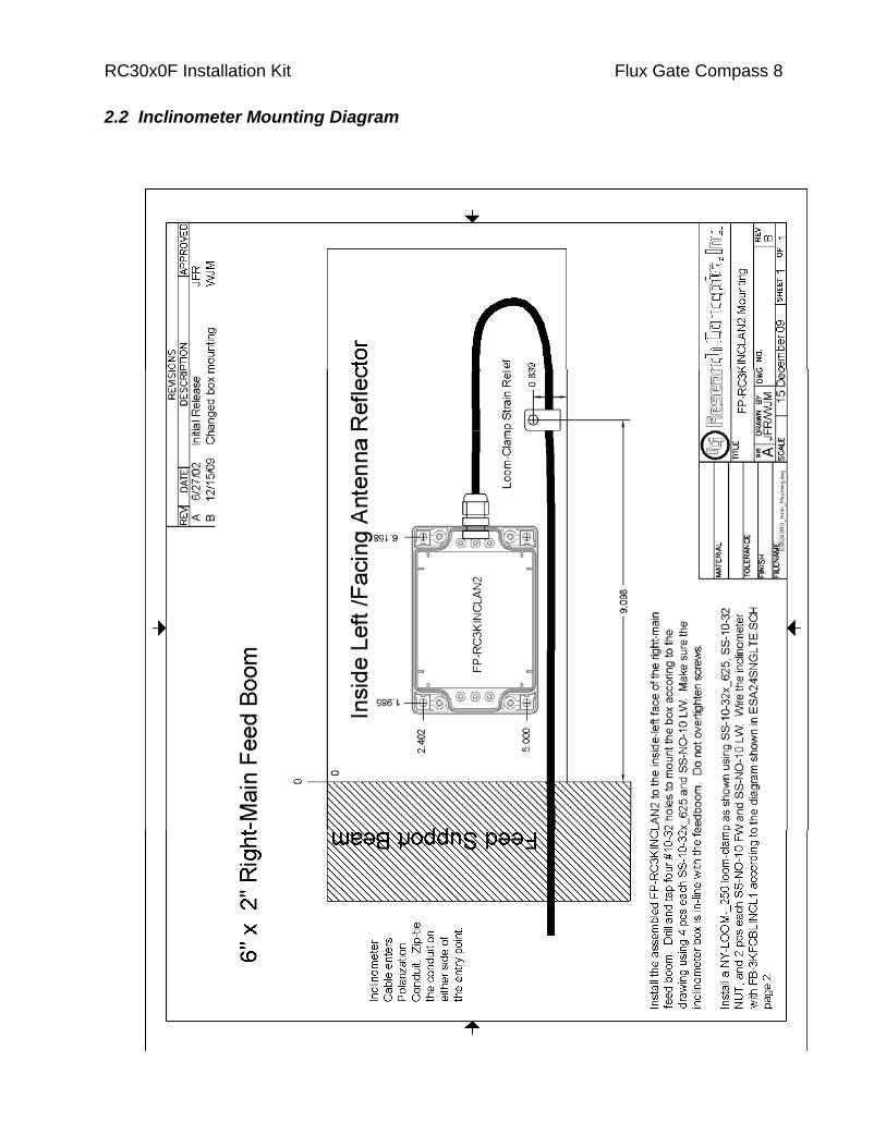
The inclinometer assembly (RCI p/n FP-RC3KINCLAN2) is housed in a NEMA rated enclosure which is installed near the end of the right feed boom inside the plastic cover that protects the RF components and feed assembly. In this context ‘right’ is as seen by an observer standing behind the reflector looking ‘through’ the reflector. The inclinometer is supplied with the interface cable (RCI p/n FB-3KFCBLINCL1) attached.
To install the inclinometer the cable must be disconnected. To remove the cable, remove the cover from the inclinometer box and disconnect the cable conductors from the terminal strip. The terminal strip has spring loaded clamps that secure the wires. To remove a wire from the terminal strip use a small, straight bladed screwdriver in the opening in the top of the terminal strip to depress each wire clamp. Loosen the collar on the liquid tight strain relief to detach the cable from the enclosure.
The mounting hole pattern and installation instructions are documented on the diagram of section 3.2. Mounting hardware is included as part of the Inclinometer Enclosure Mounting Kit described in section 3.1.1.
The inclinometer cable and polarization motor drive, resolver, and limit switch cables are enclosed in 1” convoluted tubing and routed through the right feed boom. All cables should be routed through the feedboom at the same time. After the cables are routed through the feed boom the inclinometer cable can be re-attached. A schematic diagram of the inclinometer interconnect cable is included in section 5.3 - Wiring Harness Schematic Diagrams. The following table documents the connections between the interface cable and the inclinometer.
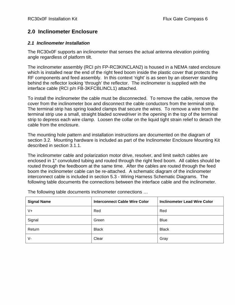
The following table documents inclinometer connections …
Signal Name Interconnect Cable Wire Color Inclinometer Lead Wire Color
V+ Red Red
Signal Green Blue
Return Black Black
V- Clear Gray

RC30x0F Installation Kit Flux Gate Compass 7
2.1.1 Inclinometer Enclosure Mounting Kit
The RC30x0F Installation Kit includes the hardware to attach the inclinometer enclosure to the right feed boom and to secure the inclinometer interconnect cable to the feed boom. These materials are contained in the Inclinometer Enclosure Mounting Kit (RCI p/n FB-3KFHDKIT4).
Here are the contents of that kit …
Quan RCI P/N Description
5 SS-10-32X_625 #10-32X5/8" Socket Head Screw, stainless steel. Used to secure the inclinometer box (quan 4), and to secure the loom clamp for the inclinometer cable (quan 1).
6 SS-NO-10 LW #10 Lock Washer, stainless steel. Used to secure the inclinometer enclosure (quan 4), and the inclinometer cable loom clamp (quan 2).
2 SS-NO-10 FW #10 Flat Washer, stainless steel, used to secure the inclinometer cable loom clamp.
5 SS-10-32 NUT #10 Nut, stainless steel. Used to secure the inclinometer enclosure (quan 4) and the inclinometer cable loom clamp (quan 1).
1 NY-_25 UV LOOM Loom Clamp, 1/4”, nylon. Used to secure the inclinometer cable at the end of the feed boom.
1 A copy of this list.
Manufacturer’s part numbers for these items are included in the bill of materials for the FP-RC3KFHDKIT described in Appendix A.
RC30x0F Installation Kit Flux Gate Compass 8
2.2 Inclinometer Mounting Diagram
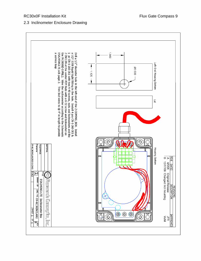
RC30x0F Installation Kit Flux Gate Compass 9 2.3 Inclinometer Enclosure Drawing

RC30x0F Installation Kit Flux Gate Compass 10

RC30x0F Installation Kit Flux Gate Compass 11
RC30x0F Installation Kit Flux Gate Compass 12
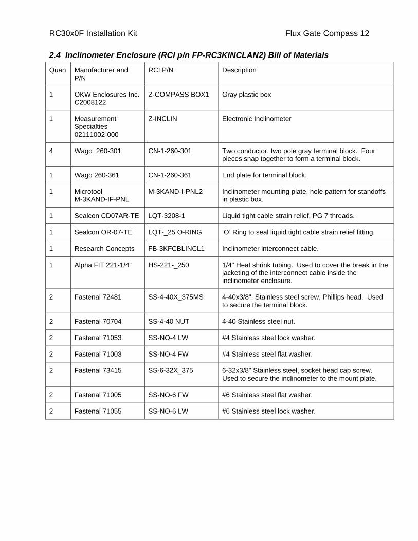
2.4 Inclinometer Enclosure (RCI p/n FP-RC3KINCLAN2) Bill of Materials
Quan Manufacturer and P/N
RCI P/N Description
1 OKW Enclosures Inc. C2008122
Z-COMPASS BOX1 Gray plastic box
1 Measurement Specialties 02111002-000
Z-INCLIN Electronic Inclinometer
4 Wago 260-301 CN-1-260-301 Two conductor, two pole gray terminal block. Four pieces snap together to form a terminal block.
1 Wago 260-361 CN-1-260-361 End plate for terminal block.
1 Microtool M-3KAND-IF-PNL
M-3KAND-I-PNL2 Inclinometer mounting plate, hole pattern for standoffs in plastic box.
1 Sealcon CD07AR-TE LQT-3208-1 Liquid tight cable strain relief, PG 7 threads.
1 Sealcon OR-07-TE LQT-_25 O-RING ‘O’ Ring to seal liquid tight cable strain relief fitting.
1 Research Concepts FB-3KFCBLINCL1 Inclinometer interconnect cable.
1 Alpha FIT 221-1/4” HS-221-_250 1/4" Heat shrink tubing. Used to cover the break in the jacketing of the interconnect cable inside the inclinometer enclosure.
2 Fastenal 72481 SS-4-40X_375MS 4-40x3/8", Stainless steel screw, Phillips head. Used to secure the terminal block.
2 Fastenal 70704 SS-4-40 NUT 4-40 Stainless steel nut.
2 Fastenal 71053 SS-NO-4 LW #4 Stainless steel lock washer.
2 Fastenal 71003 SS-NO-4 FW #4 Stainless steel flat washer.
2 Fastenal 73415 SS-6-32X_375 6-32x3/8" Stainless steel, socket head cap screw. Used to secure the inclinometer to the mount plate.
2 Fastenal 71005 SS-NO-6 FW #6 Stainless steel flat washer.
2 Fastenal 71055 SS-NO-6 LW #6 Stainless steel lock washer.
RC30x0F Installation Kit Flux Gate Compass 13
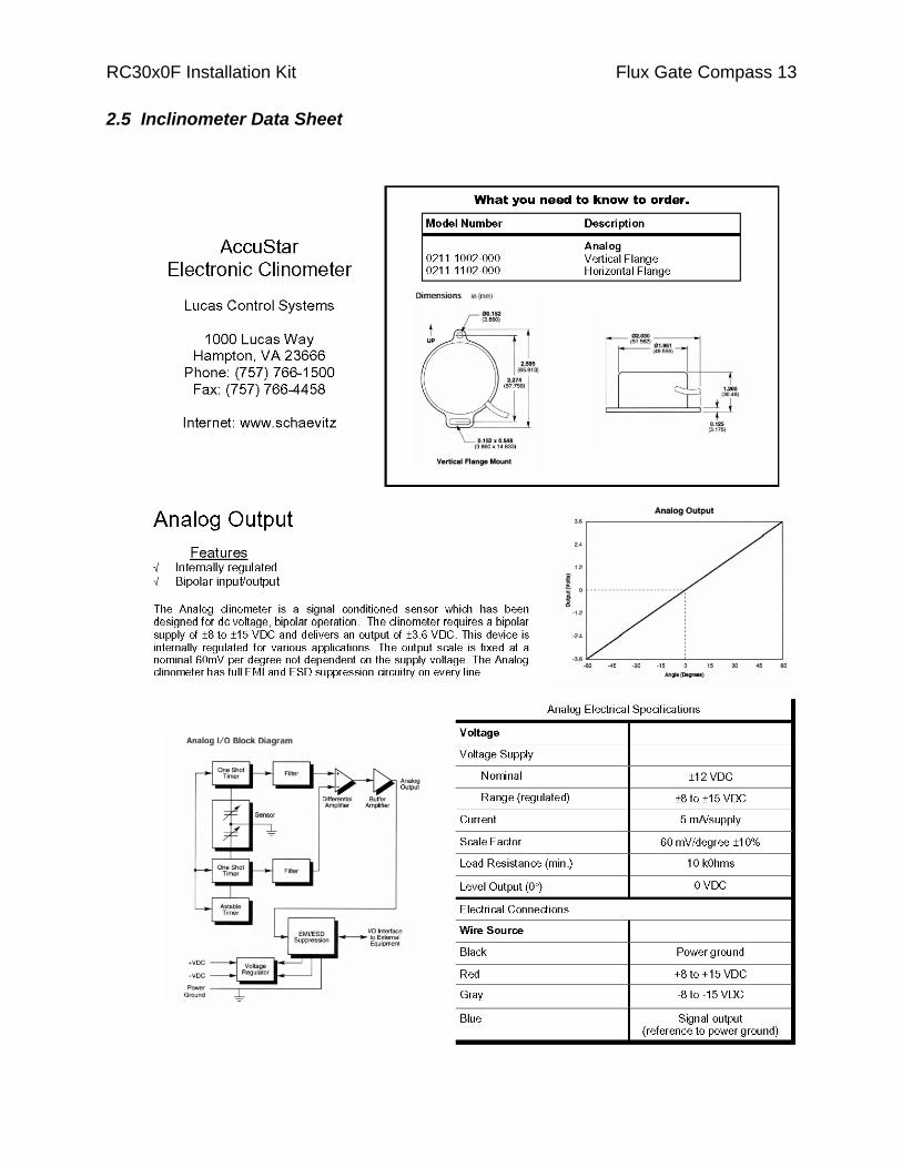
2.5 Inclinometer Data Sheet
RC30x0F Installation Kit
3.0 Flux Gate Compass This section documents the installation and construction of the optional (RC3000F only) flux gate compass assembly. The Research Concepts (RCI) part number for the flux gate compass kit is FP-RC3KFGCBLAN. The flux gate kit consists of flux gate compass assembly (RCI p/n RC3KFG5) an installation kit (RCI p/n FB-3KFANDKIT1) and conduit kit (RCI p/n FB-3KFANDCDT1) .
On the Andrew 2.4 meter antenna, the compass is installed inside the back structure of the antenna near the top of the reflector. When the antenna is deployed, the RC3000F obtains the heading of the vehicle. Mounting the compass in this manner enhances the accuracy of the measurement. When the antenna is deployed the separation between the compass and ferrous metals in the vehicle (and other vehicles in the vicinity) is increased. Ferrous metal causes distortion of the earth’s magnetic field, which degrades the accuracy of the heading measurement.
Section 4.1 describes the flux gate compass installation. Section 4.2 provides a bill of materials for the flux gate kit.
3.1 Flux Gate Compass Installation
The flux gate compass kit includes all necessary cabling and connectors. The compass is supplied with all cabling attached. As supplied from the factory the flux gate can be connected to the RC3000F antenna controller (the flux gate is tested in this configuration before the unit is shipped). An overview of the installation procedure is presented in section 4.1.1. A drawing of the flux gate compass kit is included in section 4.1.2. Section 4.1.3 includes step by step installation instructions. Section 4.1.4 provides a drill template for the holes that must be drilled in the antenna back structure.
3.1.1 Installation Overview
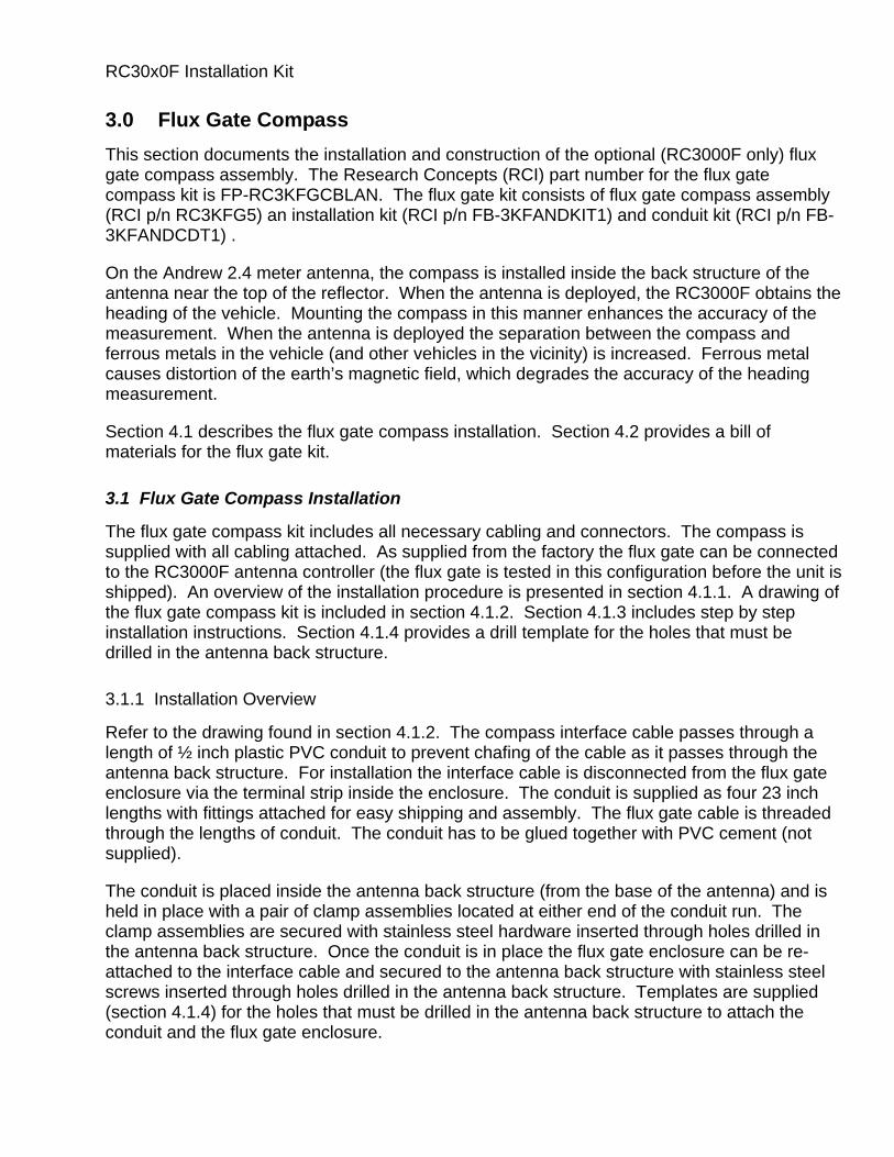
Refer to the drawing found in section 4.1.2. The compass interface cable passes through a length of ½ inch plastic PVC conduit to prevent chafing of the cable as it passes through the antenna back structure. For installation the interface cable is disconnected from the flux gate enclosure via the terminal strip inside the enclosure. The conduit is supplied as four 23 inch lengths with fittings attached for easy shipping and assembly. The flux gate cable is threaded through the lengths of conduit. The conduit has to be glued together with PVC cement (not supplied).
The conduit is placed inside the antenna back structure (from the base of the antenna) and is held in place with a pair of clamp assemblies located at either end of the conduit run. The clamp assemblies are secured with stainless steel hardware inserted through holes drilled in the antenna back structure. Once the conduit is in place the flux gate enclosure can be re-attached to the interface cable and secured to the antenna back structure with stainless steel screws inserted through holes drilled in the antenna back structure. Templates are supplied (section 4.1.4) for the holes that must be drilled in the antenna back structure to attach the conduit and the flux gate enclosure.

RC30x0F Installation Kit The interface cable is secured to the side of the antenna back structure (with a cable tie and stainless steel hardware - a hole must be drilled) and at the elevation resolver bracket (with a cable tie).
Flux Gate Compass 16
3.1.2 Flux Gate Assembly
RC30x0F Installation Kit

RC30x0F Installation Kit Flux Gate Compass 17
3.1.3 Detailed Flux Gate Installation Instructions
The flux gate installation procedure is detailed in this section.
1. The flux gate compass cable must be disconnected from the terminal strip inside the flux gate enclosure. i) Remove the cover from the flux gate enclosure. Unscrew the 4 inner screws only. Do not remove the 4 outer 10-32 screws. These screws need to stay mounted to the lid for installation on the antenna back support. ii) Disconnect the wires from the terminal strip. The terminal strip has spring loaded clamps securing the wires. Place a small straight bladed screwdriver in the opening in the top of the terminal strip and depress the spring clamp to remove each wire. iii) Loosen the collar on the liquid tight strain relief to detach the cable from the enclosure.
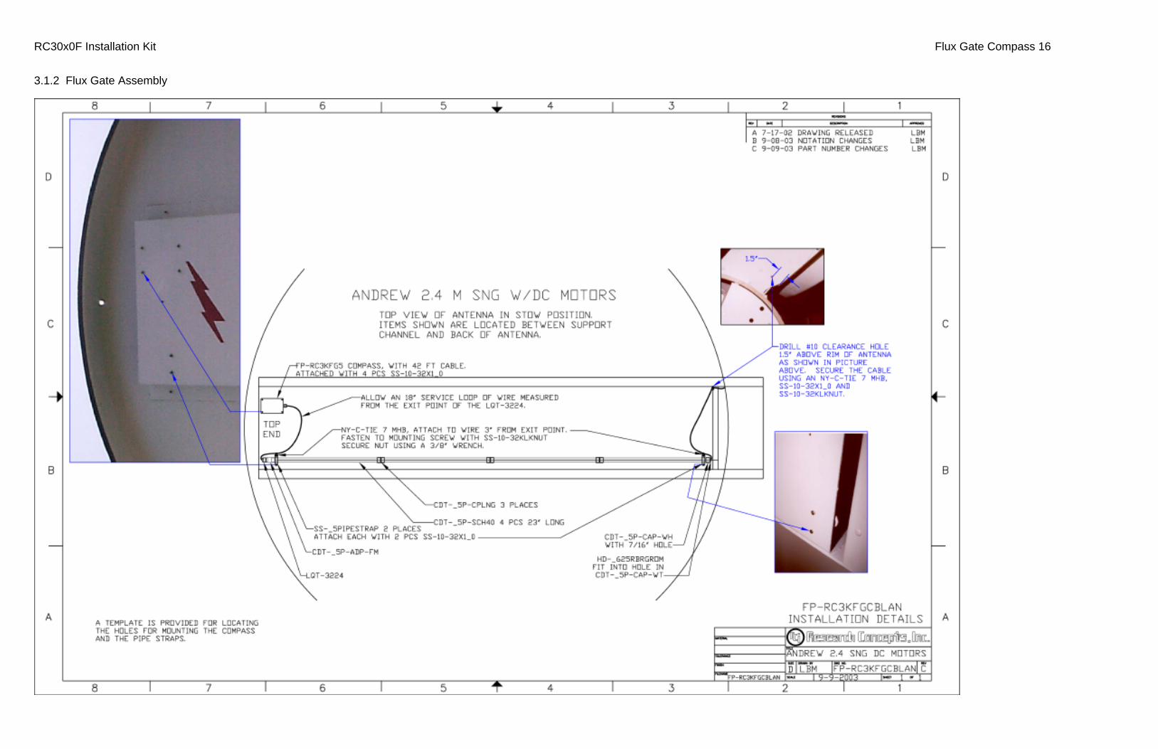
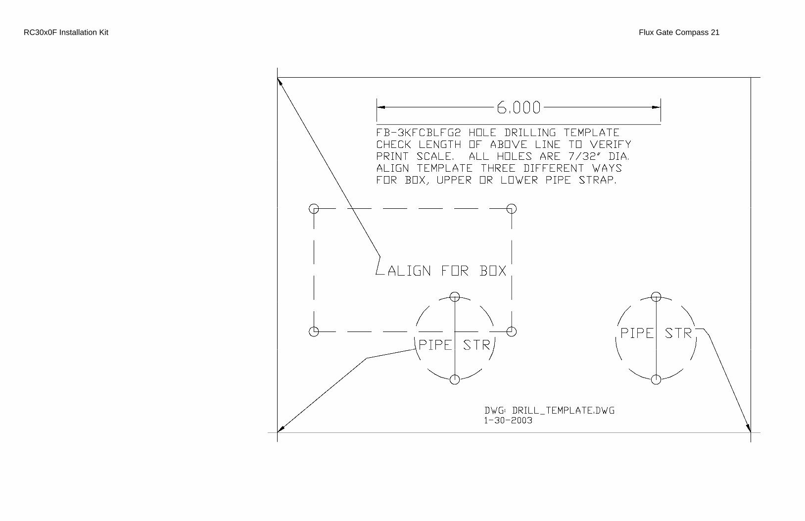
2. Use the drill template provided in section 4.1.4 to drill 3 sets of 7/32 inch diameter holes in the antenna backstructure. These holes will be used to mount the flux gate enclosure along with the upper and lower cable conduit clamps. Note that the drill template includes a set of marks 6 inches apart. Measure the separation of the marks to insure that the size of the drill template has not been reduced or expanded in the document production process. Also included in section 4.1.4 is a drawing that depicts the placement of the template on the antenna backstructure.
3. Drill a hole 7/32 inch in diameter 1.5 inches above the lip of the antenna (assuming that the antenna is stowed) on the right hand side of the antenna backstructure (as viewed from behind the antenna) near the elevation drive capstan. The location of this hole is depicted in the photo in the 2 o’clock position of the Flux Gate Assembly drawing found in section 4.1.2. This hole will be used to retain a cable clamp.
4. Verify that there is an 18 inch length of cable protruding from the liquid tight cable strain relief (LQT-3224 on the Flux Gate Assembly drawing). If necessary, loosen the collar of the strain relief and adjust the cable length. Be sure to re-tighten the collar if the collar is loosened. Securely fasten a strain relief wire tie (wire tie with a mounting hole for a #10 stud, NY-C-TIE 7 MHB) to the cable at a point 3 inches away from where the cable exits the liquid tight strain relief.
5. Assemble the conduit using PVC cement (not supplied). Avoid getting cement on the cable.
6. Tug gently on the cable at the grommet end of the conduit assembly. This will remove any excess cable from inside the conduit. Excess cable in the conduit assembly could eventually work its way out of the conduit and possible protrude from the antenna backstructure. This could lead to damage of the cable if the antenna is located atop a vehicle. Securely fasten a strain relief wire tie (wire tie with a mounting hole for a #10 stud, NY-C-TIE 7 MHB) to the cable at a point 3 inches away from where the cable exits the grommet.


RC30x0F Installation Kit Flux Gate Compass 19
7. From the base of the antenna. Insert the end of the conduit with the liquid tight strain relief (with 18 inches of cable protruding) into the antenna back structure. Secure the conduit assembly to the back structure using a pair of SS-_PIPESTRAP clamp assemblies attached with 1 inch, #10, stainless steel screws (SS-10-32X1_0) and lock washers (SS-NO-10 LW). Secure the clamp at the lower end of the conduit assembly first.
8. Reconnect the wires to the terminal strip inside the flux gate enclosure. The proper wire colors are depicted on the connector legend found on the plate the terminal strip is mounted to. Use a small, straight blade screwdriver to depress the clamp in terminal strip and insert the wire taking care to avoid clamping the wire on the insulation. Tighten the collar of the flux gate enclosure’s liquid tight strain relief to secure the interface cable. Replace the enclosure cover.
9. After the lid has been attached to the flux gate box base, unscrew the four 10-32 x 2 machine screws w/lock washers. Snap two cover plates (provided with the flux gate compass) over the screw holes. Position the enclosure under the four mounting holes. Verify that the Compass Reference indicator on the ‘top’ of the flux gate enclosure is pointing towards the reflector and that the cable strain relief in the enclosure is oriented so that it points to the base of the antenna. Secure the flux gate enclosure to the back structure using four 20-32 x 2 machine screws already removed. These screws will first slide through a ¾ spacer, then a ¾ coupling nut inside the box. The coupling nut will draw tight in the enclosure to hold the box to the back structure.
10. In this step the strain relief cable ties attached to the cable in steps 4 and 6 of this procedure are fastened to the screws that hold the conduit clamp assemblies (SS-_PIPESTRAP) in place. The ties are secured with #10 Keps style lock nuts (a nut with star washer attached, SS-10-32-KLKNUT) to the portion of the conduit clamp mounting screw that protrudes into the cavity formed by the antenna back structure and the reflector. The strain relief cable ties are attached to the ‘inner’ conduit clamp mounting screws farthest away from the outer edge of the antenna back structure. Use a 3/8 inch box wrench to tighten the Keps lock nut.
11. In this step a strain relief cable tie will be secured to the antenna back structure using hardware secured to the hole drilled in step 3 of this procedure. Loosely attach a strain relief cable tie to the interface cable below the lower conduit clamp assembly attachment point. Insert a #10 screw into the mounting hole and place the strain relief cable tie over the threaded portion of the screw inside the cavity formed by the back structure. Hold the strain relief cable tie in position with one hand and slide the cable through the loosely bound cable tie to remove all slack in the cable between the lower conduit clamp and the loosely bound cable tie. When the slack is removed, tighten the cable tie around the interface cable and secure to the side of the back structure using a one inch, #10, stainless steel screw (SS-10-32X1_0), a lock washer (SS-NO-10 LW), and a Keps style lock nut (SS-10-32-KLKNUT).
12. Secure the flux gate interface cable to the resolver bracket using a cable tie.

RC30x0F Installation Kit Flux Gate Compass 20 3.1.4 Drill Templates
RC30x0F Installation Kit Flux Gate Compass 21
RC30x0F Installation Kit Flux Gate Compass 22
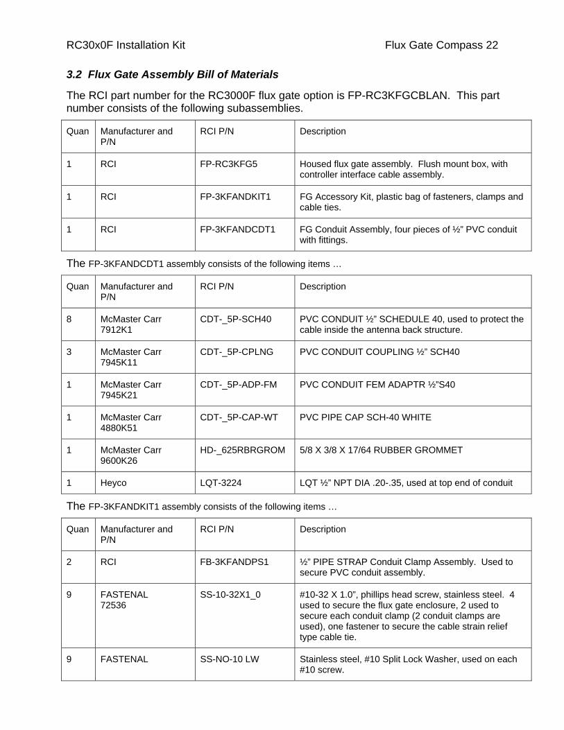
3.2 Flux Gate Assembly Bill of Materials
The RCI part number for the RC3000F flux gate option is FP-RC3KFGCBLAN. This part number consists of the following subassemblies.
Quan Manufacturer and P/N
RCI P/N Description
1 RCI FP-RC3KFG5 Housed flux gate assembly. Flush mount box, with controller interface cable assembly.
1 RCI FP-3KFANDKIT1 FG Accessory Kit, plastic bag of fasteners, clamps and cable ties.
1 RCI FP-3KFANDCDT1 FG Conduit Assembly, four pieces of ½” PVC conduit with fittings.
The FP-3KFANDCDT1 assembly consists of the following items …
Quan Manufacturer and P/N
RCI P/N Description
8 McMaster Carr 7912K1
CDT-_5P-SCH40 PVC CONDUIT ½” SCHEDULE 40, used to protect the cable inside the antenna back structure.
3 McMaster Carr 7945K11
CDT-_5P-CPLNG PVC CONDUIT COUPLING ½” SCH40
1 McMaster Carr 7945K21
CDT-_5P-ADP-FM PVC CONDUIT FEM ADAPTR ½”S40
1 McMaster Carr 4880K51
CDT-_5P-CAP-WT PVC PIPE CAP SCH-40 WHITE
1 McMaster Carr 9600K26
HD-_625RBRGROM 5/8 X 3/8 X 17/64 RUBBER GROMMET
1 Heyco LQT-3224 LQT ½” NPT DIA .20-.35, used at top end of conduit
The FP-3KFANDKIT1 assembly consists of the following items …
Quan Manufacturer and P/N
RCI P/N Description
2 RCI FB-3KFANDPS1 ½” PIPE STRAP Conduit Clamp Assembly. Used to secure PVC conduit assembly.
9 FASTENAL 72536
SS-10-32X1_0 #10-32 X 1.0”, phillips head screw, stainless steel. 4 used to secure the flux gate enclosure, 2 used to secure each conduit clamp (2 conduit clamps are used), one fastener to secure the cable strain relief type cable tie.
9 FASTENAL SS-NO-10 LW Stainless steel, #10 Split Lock Washer, used on each #10 screw.
RC30x0F Installation Kit Flux Gate Compass 23
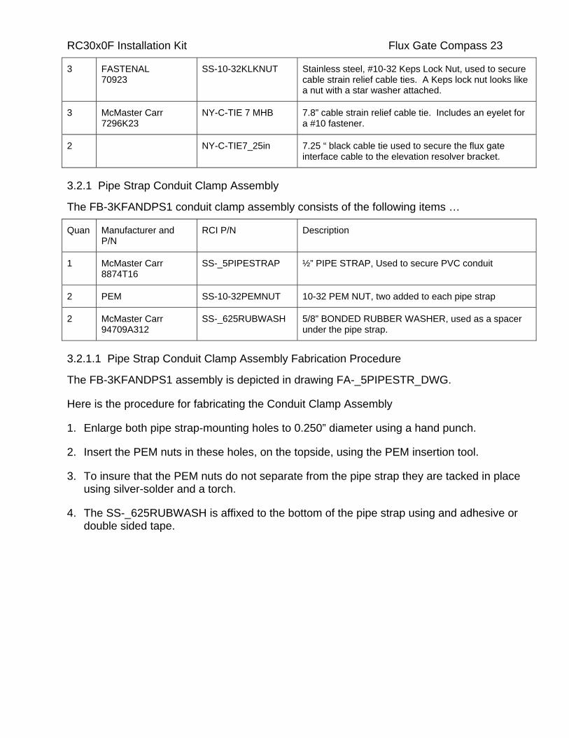
3 FASTENAL 70923
SS-10-32KLKNUT Stainless steel, #10-32 Keps Lock Nut, used to secure cable strain relief cable ties. A Keps lock nut looks like a nut with a star washer attached.
3 McMaster Carr 7296K23
NY-C-TIE 7 MHB 7.8” cable strain relief cable tie. Includes an eyelet for a #10 fastener.
2 NY-C-TIE7_25in 7.25 “ black cable tie used to secure the flux gate interface cable to the elevation resolver bracket.
3.2.1 Pipe Strap Conduit Clamp Assembly
The FB-3KFANDPS1 conduit clamp assembly consists of the following items …
Quan Manufacturer and P/N
RCI P/N Description
1 McMaster Carr 8874T16
SS-_5PIPESTRAP ½” PIPE STRAP, Used to secure PVC conduit
2 PEM SS-10-32PEMNUT 10-32 PEM NUT, two added to each pipe strap
2 McMaster Carr 94709A312
SS-_625RUBWASH 5/8” BONDED RUBBER WASHER, used as a spacer under the pipe strap.
3.2.1.1 Pipe Strap Conduit Clamp Assembly Fabrication Procedure
The FB-3KFANDPS1 assembly is depicted in drawing FA-_5PIPESTR_DWG.
Here is the procedure for fabricating the Conduit Clamp Assembly
1. Enlarge both pipe strap-mounting holes to 0.250” diameter using a hand punch.
2. Insert the PEM nuts in these holes, on the topside, using the PEM insertion tool.
3. To insure that the PEM nuts do not separate from the pipe strap they are tacked in place using silver-solder and a torch.
4. The SS-_625RUBWASH is affixed to the bottom of the pipe strap using and adhesive or double sided tape.

RC30x0F Installation Kit Antenna Wiring Harness 24
4.0 Antenna Wiring Harness RC30x0F controllers interface to the antenna via ten flexible cables. The cables interface to the following antenna components …
• Az/El/Pol Resolvers (3 cables)
• Inclinometer (1 cable)
• Az/El Motor/Brake Assemblies (2 cables)
• Pol Motor (1 cable)
• Azimuth CW/CCW Limit switch (1 cable)
• Polarization CW/CCW Limit switch (1 cable)
• Elevation Sync switch (1 cable)
If the optional flux gate compass is included for the RC3000 controller, the compass is installed near the top of the antenna back structure. The interconnect cable for the flux gate compass is attached to the compass. Installation of the flux gate compass is documented in section 4. of this document.
This section contains …
• Installation instructions for the 1.5” convoluted tubing that protects the wiring harness where the harness exits mount along with a bill of materials for the convoluted tubing installation kit (section 5.1).
• Installation instructions for the polarization motor wiring harness and a modification to the pol limit switch wiring harness (section 5.2).
• Schematic diagrams for the wiring harness (section 5.3).
• Contact arrangements for the connectors in the wiring harness (section 5.4).
• Connector and cable schedule for the wiring harness. This lists manufacturer’s part numbers for the connectors and cabling used in the wiring harness (section 5.5)
4.1 Convoluted Tubing Installation
1.5” convoluted tubing is employed to protect the controller to mount interconnect cables as the cables pass through the pedestal at the azimuth pivot point. 1” convoluted tubing is employed for the wiring that runs through the feed boom.
The original Andrew 2.4 meter SNG mount was powered by AC motors. That mount utilized a single piece of 1” convoluted tubing (approximately 130” long) that ran through the feed boom and pedestal. The az/el motor/brake and pol motor interface cables were not placed in the convoluted tubing.

RC30x0F Installation Kit Antenna Wiring Harness 25 For the Andrew 2.4 meter mount powered by DC motors, 1” convoluted tubing (90” length) is used in the feedboom and 1.5” convoluted tubing (48” length) is used to protect the wiring harness as the cables exit the mount pedestal. Note that the required length of 1.5” convoluted tubing is included with this kit while 1” convoluted tubing is not included. Andrew drawing 301135 describes the 1” convoluted tubing.
The 1” and 1.5” convoluted tubing are joined at the cable tie point above the azimuth pivot point. There should be 4” of overlap between the 1” and 1.5” split convoluted tubing centered on the cable tie point. Use a 20” cable tie to secure both lengths of convoluted tubing to the tie point. Use 10 7.25” cable ties to secure the 1.5” convoluted tubing around the wiring harness.
All of the interconnect cables should pass through the 1.5” convoluted tubing. The polarization motor drive, resolver, and limit switch cables should pass the 1” convoluted tubing. All other cables should exit the bundle at the end of the 1.5” convoluted tubing near the splice with the 1” convoluted tubing.
The RC30x0F Installation Kit includes the 1.5” convoluted tubing and the hardware required to install the convoluted tubing. These materials are contained in the Interconnect Cabling Installation Kit (RCI p/n FB-3KFHDKIT1).
Here are the contents of that kit …
Quan RCI P/N Description
48” CDT-492.150 1 1/2" Convoluted Tubing. Place on the wiring harness where the wiring harness exits the pedestal. Overlap 4” with the 1” convoluted tubing coming from the feed boom.
1 NY-C-TIE_5X20 Cable Tie, 20 inch, black. Used to secure the 1 ½” convoluted tubing and the 1” convoluted tubing together at the cable tie point in the pedestal enclosure.
10 NY-C-TIE 7_25” Cable Tie, 7.25 inch, black. Used to secure the 1 ½” convoluted tubing.
1 A copy of this list.
Manufacturer’s part numbers for these items are included in the bill of materials for the FP-RC3KFHDKIT described in Appendix A.
4.2 Polarization Motor Wiring Harness Installation and Limit Switch Modification
Polarization Motor
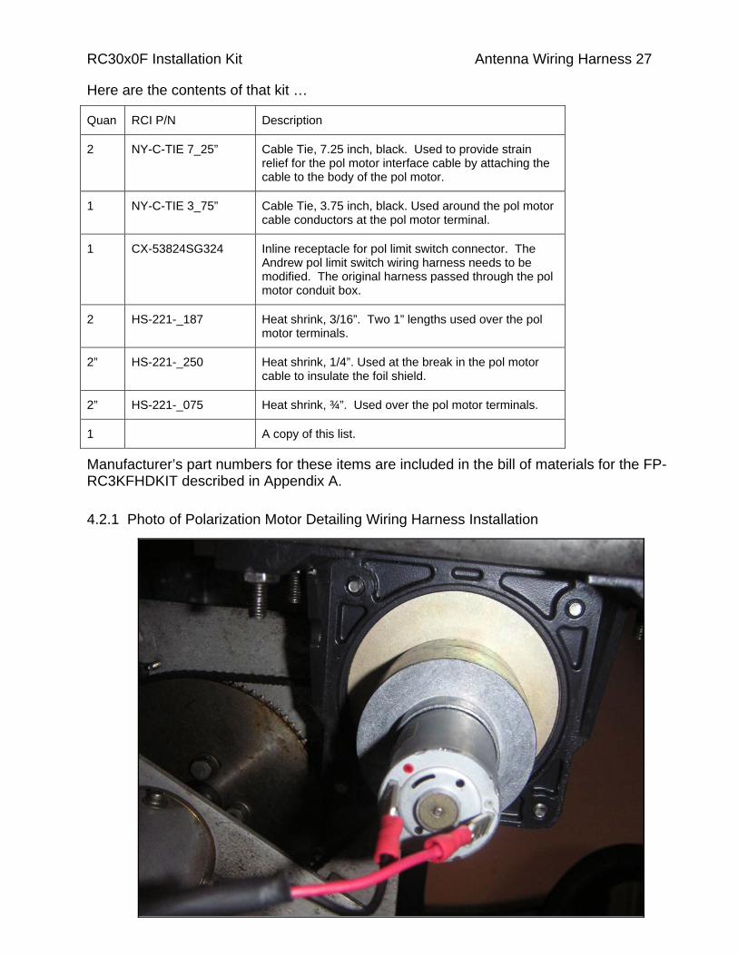
The polarization motor is equipped with solder terminals labeled ‘+’ and ‘-‘. The FB-3KFCBLPOLM2 cable assembly has a pigtail on one end and a ConXall connector that interfaces to the polarization motor interconnect cable on the other end. A photo of the installed cable assembly is included in section 5.2.1.
RC30x0F Installation Kit Antenna Wiring Harness 26
Here is the installation procedure for the FB-3KFCBLPOLM2 cable assembly …
1. The motor end of the cable assembly should be a pigtail formed by removing the cable jacket, shield, and drain wire. Strip ¼” of insulation on each conductor and tin the bare wire. Place the ¼” heatshrink over break in the cable jacket material.
2. Thread ¾” heatshrink over the cable assembly.
3. Crimp CN-159-2187 onto both wires install black wire onto red tab.
4. Use a 3.75” cable tie to secure the motor conductors together near the motor terminals.
5. Place the ¾” heat shrink over the motor terminals.
6. Use a 7.25” cable tie over the ¾” heat shrink to secure the motor drive conductors to the body of the motor to provide strain relief.
7. Loop the motor wire towards the end of the motor opposite the shaft and place a second 7.25” cable tie over the cable jacketing material and around the body of the motor.
Limit Switch Modification
The original Andrew 2.4 meter SNG mount equipped with AC motor employed a polarization motor that had an attached conduit box. The conduit box had a bulkhead type receptacle for the pol limit switch interface cable. The pol limit switch wiring harness exited the conduit box via a liquid tight strain relief.
The DC polarization motor used with the RC3000F does not include a conduit box. To use the original pol limit switch wiring harness with a DC motor the limit switch wiring harness needs to be fitted with an inline cable receptacle with a backshell to block moisture. An inline cable receptacle is included with this kit. The connections for the inline cable receptacle are identical to those of the bulkhead receptacle and are detailed in wiring harness schematic diagram for the pol motor found in section 5.3.
The Andrew pol limit switch wiring harness needs to be modified. The original harness passed through the pol motor conduit box.
The RC30x0F Installation Kit includes the hardware required to connect the FB-3KFCBLPOLM2 cable to the polarization motor and the inline receptacle that has to be fitted to the polarization limit switch wiring harness. These materials are contained in the Polarization Installation Kit (RCI p/n FB-3KFHDKIT5).
RC30x0F Installation Kit Antenna Wiring Harness 27
Here are the contents of that kit …
Quan RCI P/N Description
2 NY-C-TIE 7_25” Cable Tie, 7.25 inch, black. Used to provide strain relief for the pol motor interface cable by attaching the cable to the body of the pol motor.
1 NY-C-TIE 3_75” Cable Tie, 3.75 inch, black. Used around the pol motor cable conductors at the pol motor terminal.
1 CX-53824SG324 Inline receptacle for pol limit switch connector. The Andrew pol limit switch wiring harness needs to be modified. The original harness passed through the pol motor conduit box.
2 HS-221-_187 Heat shrink, 3/16”. Two 1” lengths used over the pol motor terminals.
2” HS-221-_250 Heat shrink, 1/4”. Used at the break in the pol motor cable to insulate the foil shield.
2” HS-221-_075 Heat shrink, ¾”. Used over the pol motor terminals.
1 A copy of this list.
4.2.1 Photo of Polarization Motor Detailing Wiring Harness Installation
Manufacturer’s part numbers for these items are included in the bill of materials for the FP-RC3KFHDKIT described in Appendix A.
Wiring Harness Schematic Diagrams (page 1 of 3) RC3000F Installation Kit Antenna Wiring Harness 28
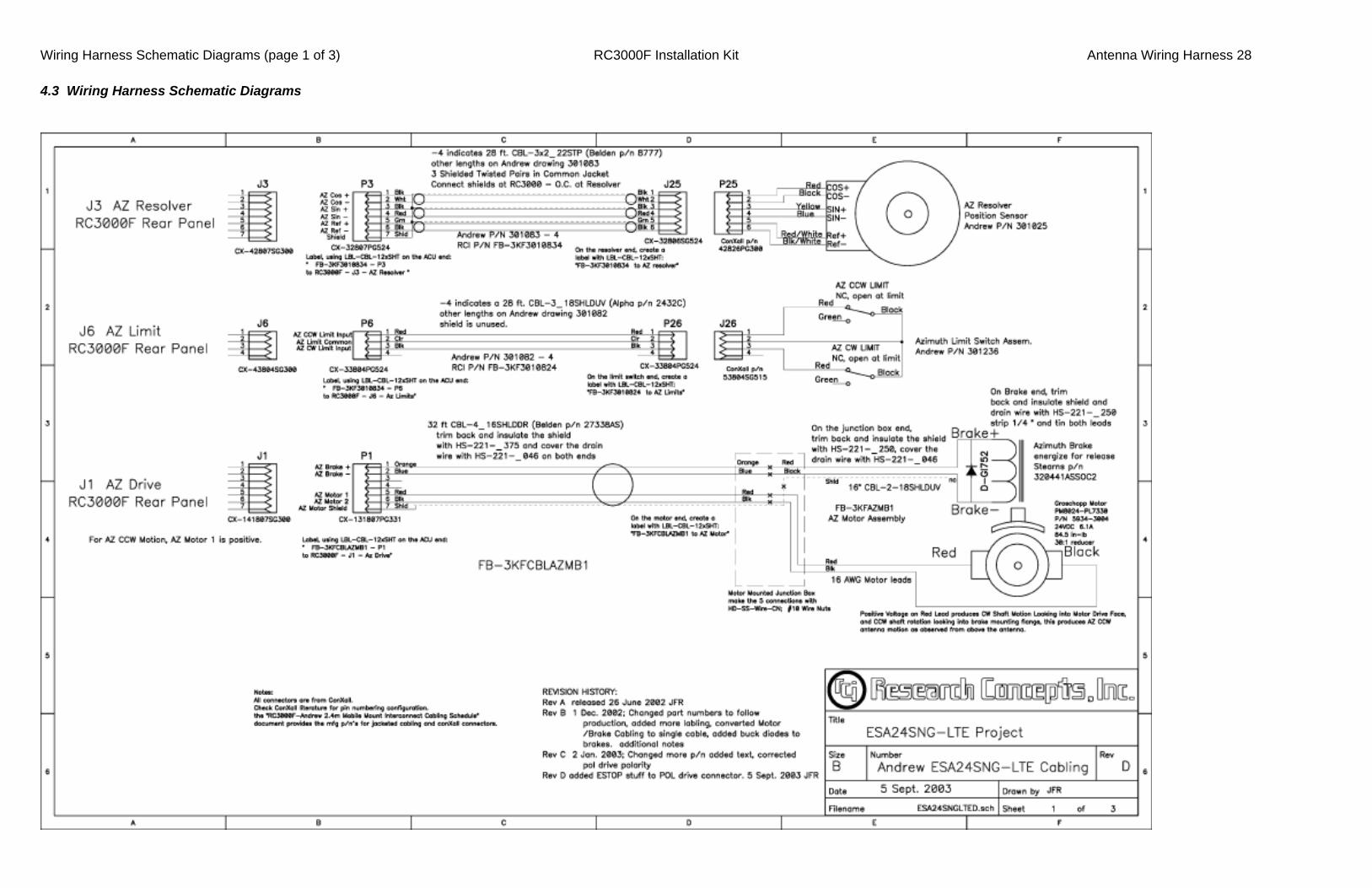
4.3 Wiring Harness Schematic Diagrams

Wiring Harness Schematic Diagrams (page 2 of 3) RC3000F Installation Kit Antenna Wiring Harness 29
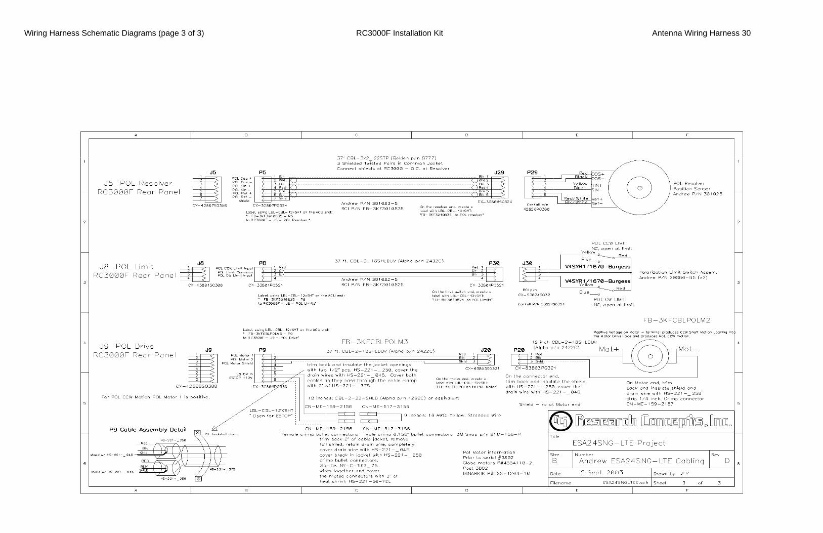
(page 3 of 3) RC3000F Installation Kit Antenna Wiring Harness 30 Wiring Harness Schematic Diagrams
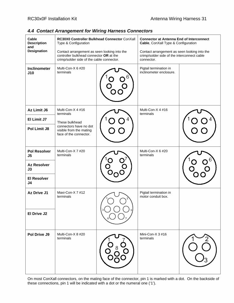
Cable Description and Designation
RC30X0 Controller Bulkhead Connector ConXall Type & Configuration
Contact arrangement as seen looking into the controller bulkhead connector OR at the crimp/solder side of the cable connector.
Connector at Antenna End of Interconnect Cable, ConXall Type & Configuration
Contact arrangement as seen looking into the crimp/solder side of the interconnect cable connector.
Inclinometer J10
Multi-Con-X 6 #20 terminals
Pigtail termination in inclinometer enclosure.
Az Limit J6
El Limit J7
Pol Limit J8
Multi-Con-X 4 #16 terminals
These bulkhead connectors have no dot visible from the mating face of the connector.
Multi-Con-X 4 #16 terminals
Pol Resolver J5
Az Resolver J3
El Resolver J4
Multi-Con-X 7 #20 terminals
Multi-Con-X 6 #20 terminals
Az Drive J1
El Drive J2
Maxi-Con-X 7 #12 terminals
Pigtail termination in motor conduit box.
Pol Drive J9 Multi-Con-X 8 #20 terminals
Mini-Con-X 3 #16 terminals
On most ConXall connectors, on the mating face of the connector, pin 1 is marked with a dot. On the backside of these connections, pin 1 will be indicated with a dot or the numeral one (‘1’).
4.4 Contact Arrangement for Wiring Harness Connectors
RC30x0F Installation Kit Antenna Wiring Harness 31

Note [1] – RCI p/n FP-RC3KFHDKIT1 includes installation hardware for the cable harness, az/el motor brake assemblies, and the inclinometer enclosure. Packaged as five kits labeled … Interconnect Cabling RCI p/n FB-3KFHDKIT1, Azimuth Motor RCI p/n FB-3KFHDKIT2, Elevation Motor RCI p/n FB-3KFHDKIT3, Inclinometer RCI p/n FB-3KFHDKIT4, and Polarization RCI p/n FB-3KFHDKIT5.
Cable Description and Designation
See Note [1]
RC30X0 Controller Bulkhead Connector, ConXall Type & Configuration, ConXall p/n, RCI p/n, (S) solder, (C) crimp
Interconnect Cable Controller Mating Connector, ConXall Type, ConXall p/n, RCI p/n, (S) solder, (C) crimp
RCI Cable Assembly p/n, Andrew Drawing Reference (25’ cables), Cable Type and Length, RCI Cable p/n
Interconnect Cable Antenna Termination, ConXall Type & Configuration, ConXall p/n, RCI p/n, (S) solder, (C) crimp
Notes …
RCI p/n in bold type, other vendor’s p/n’s italicized, (C) indicates a crimp style connector, (S) indicates a solder style connector.
Inclinometer J10 Multi-Con-X 6 #20 terminals 4282-6SG-300 CX-42826SG300 (S) 4280-6SG-300 CX-42806SG300 (C)
Multi-Con-X 3282-6PG-521 CX-32826PG521 (S) 3280-6PG-521 CX-32806PG521 (C)
FB-3KFCBLINCL1, None, Alpha 2404C, 4x22 shielded w/drain 37’, CBL-4_22SHLDUV
Pigtail termination in inclinometer enclosure.
Inclinometer enclosure RCI p/n FP-RC3KINCLAN2.
Az Limit J6
El Limit J7
FB-3KF3010824, 301082-4, Belden 8770 3x18 shielded w/drain 28’, CBL-3_18SHLDUV
Pol Limit J8
Multi-Con-X 4 #16 terminals 4382-4SG-300 CX-43824SG300 (S) 4380-4SG-300 CX-43804SG300 (C)
Multi-Con-X 3382-4PG-524 CX-33824PG524 (S) 3380-4PG-524 CX-33804PG524 (C) FB-3KF3010825, 301082-5, Belden 8770 37’
Same as other end of cable. Azimuth limit switches – Andrew drawing 301236. Elevation limit switches - Andrew drawing 301384. Pol limit switch described on Andrew drawing 20860.
Modify pol limit switch wiring harness. For the AC motors the harness ran through the pol motor conduit box. For DC Motors add an inline receptacle. . RCI p/n CX-53824SG32 (S) (Multi-Con-X 5 382 4SG 324)
Pol Resolver J5 FB-3KF3010835, 301083-5, Belden 8777, 3x22 twisted, shielded pairs w/ individual drain. 37’
Az Resolver J3
El Resolver J4
Multi-Con-X 7 #20 terminals 4282-7SG-300 CX-42827SG300 (S) 4280-7SG-300 CX-42807SG300 (C)
Multi-Con-X 3282-7PG-524 CX-32827PG524 (S) 3280-7PG-524 CX-32807PG524 (C)
FB-3KF3010834, 301083-4, Belden 8777 28’, CBL-3x2_22 STP1
Multi-Con-X 6 #20 terminals 3282-6SG-524 CX-32826SG524 (S) 3280-6SG-524 CX-32806SG524 (C)
Resolver – Andrew drawing 301025.
Az Drive J1 FB-3KFCBLAZMB1, None, Belden 27338AS, 4x16 shielded w/drain, 32’, CBL-4_16SHLDDR
El Drive J2
Maxi-Con-X 7 #12 terminals 14182-7SG-300 CX-141827SG300 (S) 14180-7SG-300 CX-141807SG300 (C)
Maxi-Con-X 13182-7PG-331 CX-131827PG331 (S) 13180-7PG-331 CX-131807PG331 (C)
FB-3KFCBLELMB1, None, Belden 27338AS 32’
Pigtail termination in motor conduit box. The interface cable connections to the motor, brake coil, and brake cable drain wire are made with set screw wire nuts (Ideal #10, RCI p/n CN-IDEAL-10)
Azimuth Integrated Motor/Brake Assembly – RCI p/n FB-3KFAZMB1. Elevation Integrated Motor/Brake Assembly – RCI p/n FB-3KFELMB1. Alpha 2422C, 2x18 shielded w/drain, RCI p/n CBL-2_18SHLDUV is routed from the brake assembly to the motor conduit box. A GI 752 diode (D-GIS752) is placed across each brake coil. The brake coil is non-polarized.
Pol Drive J9 Multi-Con-X 8 #20 terminals 4282-8SG-300 CX-42828SG300 (S) 4280-8SG-300 CX-42808SG300 (C)
Multi-Con-X 3282-8PG-521 CX-32828PG521 (S) 3280-8PG-521 CX-32808PG521 (C)
FB-3KFCBLPOLM1, 300829-17, Belden 2422C, 2x18 shielded w/drain 37’, CBL-2_18SHLDUV
Mini-Con-X 3 #16 terminals 6382-3SG-321 CX-63823SG321 (S) 6380-3SG-321 CX-63803SG321 (C)
The controller interconnect cable interfaces to a RCI p/n FB-3KFCBLPOLM2, which consists of a ConXall inline cable receptacle and 12” Alpha 2422C cable. Connector type Mini-Con-X 8382-3PG-321 (solder) RCI p/n CX-83823PG321 or Mini-Con-X 8380-3PG-321 (crimp) RCI p/n CX-83803PG321. Pol motor described on Andrew drawing 303025.
RC30x0F Installation Kit Antenna Wiring Harness 32
4.5 Connector and Cable Schedule for Wiring Harness
RC30x0F Installation Kit Controller Software Setup 33
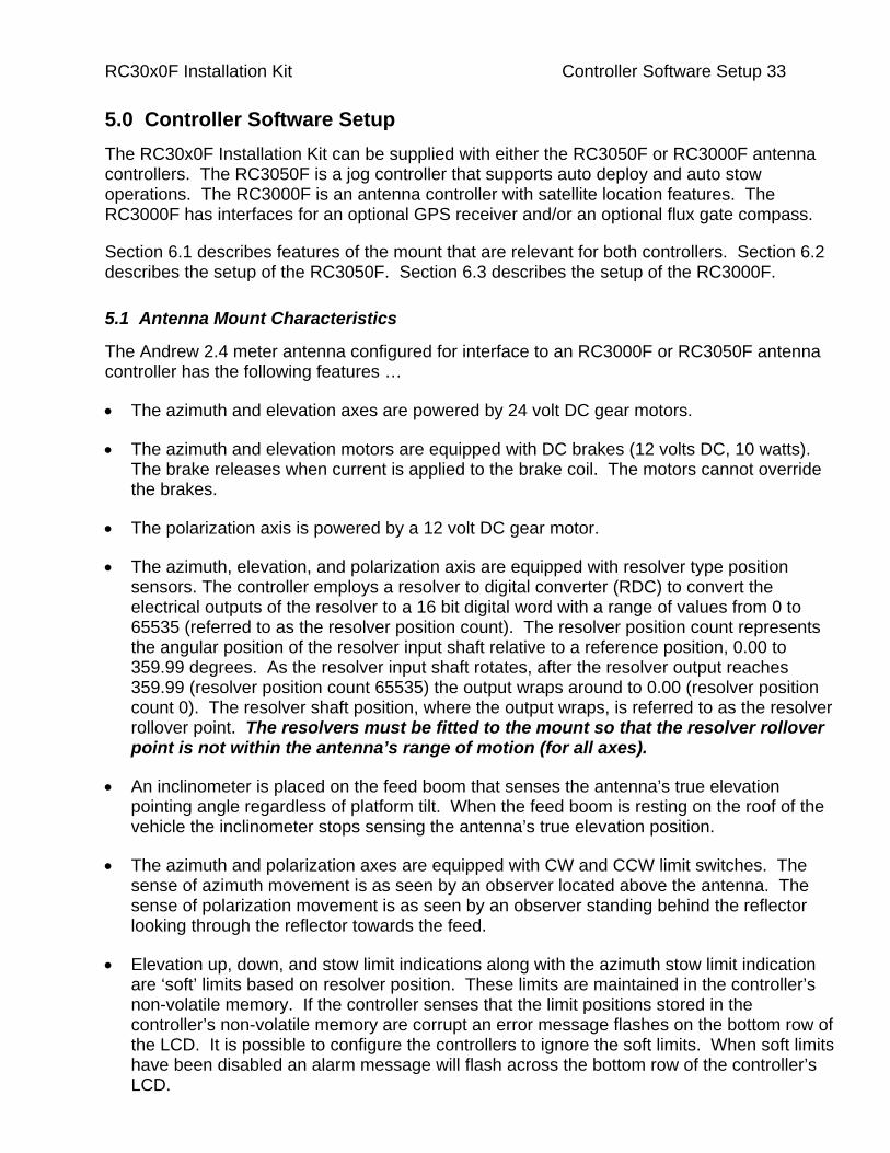
5.0 Controller Software Setup The RC30x0F Installation Kit can be supplied with either the RC3050F or RC3000F antenna controllers. The RC3050F is a jog controller that supports auto deploy and auto stow operations. The RC3000F is an antenna controller with satellite location features. The RC3000F has interfaces for an optional GPS receiver and/or an optional flux gate compass.
Section 6.1 describes features of the mount that are relevant for both controllers. Section 6.2 describes the setup of the RC3050F. Section 6.3 describes the setup of the RC3000F.
5.1 Antenna Mount Characteristics
The Andrew 2.4 meter antenna configured for interface to an RC3000F or RC3050F antenna controller has the following features …
• The azimuth and elevation axes are powered by 24 volt DC gear motors.
• The azimuth and elevation motors are equipped with DC brakes (12 volts DC, 10 watts). The brake releases when current is applied to the brake coil. The motors cannot override the brakes.
• The polarization axis is powered by a 12 volt DC gear motor.
• The azimuth, elevation, and polarization axis are equipped with resolver type position sensors. The controller employs a resolver to digital converter (RDC) to convert the electrical outputs of the resolver to a 16 bit digital word with a range of values from 0 to 65535 (referred to as the resolver position count). The resolver position count represents the angular position of the resolver input shaft relative to a reference position, 0.00 to 359.99 degrees. As the resolver input shaft rotates, after the resolver output reaches 359.99 (resolver position count 65535) the output wraps around to 0.00 (resolver position count 0). The resolver shaft position, where the output wraps, is referred to as the resolver rollover point. The resolvers must be fitted to the mount so that the resolver rollover point is not within the antenna’s range of motion (for all axes).
• An inclinometer is placed on the feed boom that senses the antenna’s true elevation pointing angle regardless of platform tilt. When the feed boom is resting on the roof of the vehicle the inclinometer stops sensing the antenna’s true elevation position.
• The azimuth and polarization axes are equipped with CW and CCW limit switches. The sense of azimuth movement is as seen by an observer located above the antenna. The sense of polarization movement is as seen by an observer standing behind the reflector looking through the reflector towards the feed.
• Elevation up, down, and stow limit indications along with the azimuth stow limit indication are ‘soft’ limits based on resolver position. These limits are maintained in the controller’s non-volatile memory. If the controller senses that the limit positions stored in the controller’s non-volatile memory are corrupt an error message flashes on the bottom row of the LCD. It is possible to configure the controllers to ignore the soft limits. When soft limits have been disabled an alarm message will flash across the bottom row of the controller’s LCD.
RC30x0F Installation Kit Controller Software Setup 34
• The mount is equipped with a single elevation ‘sync’ switch. This switch is active for a small range of elevation angles that are approximately four degrees above the elevation stow position. Elevation stow, down, and up limits are derived from the resolvers. The sync switch is monitored as the antenna deploys. The resolver position where the sync switch activates is compared to a value specified by the user that is stored in the controller’s non-volatile memory. This allows the controller to detect slippage in the resolver input shaft coupling and other resolver related faults. When the controller detects an ‘elevation sync’ error an error message flashes on the bottom row of the controller’s LCD.
5.2 RC3050F Software Setup
At the present time (January, 2003), an Operator’s Manual specific to the RC3050F has not been created. An appendix (A) has been created that documents the differences between the standard RC3050 controller and the RC3050F controller.
Section 2.3 of the appendix describes the RC3050F software setup procedure. That section of the manual has been expanded and included below (sections 6.2.1 through 6.2.16). Sections 3.2 and 3.3 of the appendix document the new screens implemented for the RC3050F. Refer to those sections of the appendix when performing the software setup procedure documented below.
The software setup procedure should be performed with the platform that the antenna is mounted on horizontal.
5.2.1 Deactivate Software Limits
In the POLARIZATION LIMIT screen (section 3.3.6 of the RC3050F appendix). Press the F/S key to deactivate software limits. “LIMITS INACTIVE!” will flash on the bottom row of the LCD.
5.2.2 Move Mount to the Azimuth Stow Position
Go to the controller’s MANUAL mode (section 3.2.1 of the standard RC3050 manual). Use the El Up/Down and Az CW/CCW keys to jog the mount. Insure that the elevation angle is high enough so that the feed boom clears all obstructions. Move the mount to exact center of azimuth travel. This azimuth position is referred to as the azimuth stow position or the azimuth reference position.. When the antenna is at the azimuth stow position the antenna can be moved below the elevation down limit to the elevation stow limit.
5.2.3 Define Azimuth Stow (Reference) Position
In this step the azimuth stow (or reference) position is set. Once the reference position is set, the displayed azimuth angle will be 0.0 when the antenna is at the azimuth stow position.
Verify that mount is at the azimuth stow position. Go the controller’s AZIM REF maintenance screen (section 3.3.2 of the RC3050F Appendix). The absolute resolver position is displayed in parens on the bottom row of the LCD. Note that the azimuth resolver must be adjusted so that the resolver rollover point does not occur within the mount’s range of azimuth travel. For most installations, when the antenna is at the azimuth stow (or reference) position, the absolute resolver position should be 180.0 +/- 10 degrees.

RC30x0F Installation Kit Controller Software Setup 35 To set the azimuth stow (or reference) position when the AZIM REF mode is active, press the UP key followed by the DOWN key to establish the current position as the azimuth stow (or reference) position.
Verify that the azimuth reference position has been set by going to MANUAL mode confirming that the displayed azimuth position is 0.0.
5.2.4 Define Elevation Inclinometer Reference Position
In this step the inclinometer reference position is set. The reference position is set by positioning the antenna so that the antenna back structure is vertical. With the back structure vertical, the antenna’s RF pointing angle is 22.3 degrees.
From MANUAL mode raise reflector to the (back structure) vertical position. Go the EL VOLTS maintenance screen. Press the UP key followed by the DOWN key to establish the current inclinometer position as the inclinometer reference position.
To verify that the reference position has been set, go the controller’s MANUAL mode and confirm that the displayed elevation position is 22.3 +/- 0.2 degrees.
5.2.5 Define Elevation Resolver Reference Position
In this step the elevation resolver reference position is set. This step is performed with the antenna back structure vertical (the antenna back structure was set to vertical in the previous step).
The elevation resolver reference position is set from the EL REF maintenance screen (see section 3.3.2 of the RC3050F Appendix). When this screen is active the absolute elevation resolver position is displayed in parens on the bottom row of the LCD. Note that the elevation resolver must be adjusted so that the resolver rollover point does not occur within the mount’s range of elevation travel. When the antenna back structure is vertical the absolute resolver position should nominally be 180.0 degrees (absolute elevation resolver positions of 110 to 270 degrees should work, however).
To set the elevation resolver reference, from the EL REF screen, hit the Up key followed by the Down key.
When software limits are active and the antenna is above the down elevation limit, the displayed elevation angle is derived from the inclinometer. When the software limits are active and the antenna is below the down elevation limit, the displayed elevation angle is derived from the elevation inclinometer. When software limits are deactivated the displayed elevation angle is derived from the inclinometer. The elevation down limit is a resolver position (specified later in the setup procedure). If the antenna is above the elevation down limit the antenna can move in azimuth. If the antenna is below the elevation down limit, the antenna can move in elevation down to the elevation stow limit.
If the antenna is not level when the elevation resolver reference is set, when the antenna is level there will be a jump in the displayed elevation position as the antenna passes through the down elevation limit.
RC30x0F Installation Kit Controller Software Setup 36 5.2.6 Determine Electronic Inclinometer Scale Factor
The inclinometer is an analog sensor. It’s output voltage varies as the inclinometer is rotated. There is some unit to unit variation in the inclinometer’s millivolt per degree (mV/deg) characteristic (or ‘scale factor’). In this step the inclinometer’s (mV/deg) characteristic is determined.
The procedure is to move the antenna over a known elevation angle determined using an adjustable ‘bubble’ type inclinometer or a level that indicates horizontal, vertical, and 45 degree inclinations. The change in inclinometer voltage is noted and the scale factor is calculated.
The first elevation angle – voltage data set is taken with the antenna back structure vertical. Go to the EL VOLTS maintenance screen and record the displayed voltage (Voltage_1 = _______ volts). At this position the angle is zero (Angle_1 = 0 degrees).
Go to MANUAL mode and move the antenna to a higher elevation angle. If an adjustable inclinometer is used rotate the antenna so that the antenna’s displacement from the ‘back structure vertical’ position is approximately 45 degrees. If a level with a fixed 45 degree offset is employed position the antenna so that the 45 degree bubble is centered.
Go back to the EL VOLTS maintenance screen and record the voltage and angle. Voltage_2 = ______ volts, Angle_2 = ______ degrees.
Calculate the elevation scale factor (mV/deg.) = …
1000 x [ (Voltage_1 - Voltage_2) / (Angle_1 - Angle_2) ].
The range of values will be 50 mV/deg +/- 5 mV/deg.
To enter the elevation scale, factor into the controller’s non-volatile memory and go to the EL SF configuration screen. Press the Up and Down keys so that the displayed value is within 0.1 of the calculated value.
To verify that the measurement was made correctly, go to MANUAL mode and confirm that the displayed elevation position is 22.3 + Angle_2.
5.2.7 Define Elevation Up Software Limit
From MANUAL mode, move the antenna to the desired elevation up limit. Go to the EL UP programming screen. Press the Up key followed by the Down key to store the resolver position in the controller’s non-volatile memory.
5.2.8 Define Elevation Down Software Limit
In this step the controller’s down elevation limit is specified. The significance of the down elevation limit was discussed in section 6.2.5. The down limit should be set at the elevation position required to avoid obstacles while moving in the antenna about the azimuth axis (typically set around 5.0 degrees).
From MANUAL mode, move the antenna to the desired elevation down limit. Go to the EL DOWN programming screen. Press the Up key followed by the Down key to store the resolver position in the controller’s non-volatile memory.
RC30x0F Installation Kit Controller Software Setup 37 5.2.9 Define Elevation Sync Software Limit
The significance of the elevation sync switch was discussed in section 6.1. The sync switch is sometimes referred to as a creep switch. The switch is located about 4 degrees above the typical elevation stow position. When the antenna is stowed in elevation the controller switches to slow elevation movement when the elevation sync switch is encountered.
From MANUAL mode, move the antenna in elevation to the position where the sync switch activates (when the sync switch is active a period, ‘.’, is displayed to the left of the elevation limit field, on the second row of the LCD under the elevation position field).
Go to the EL SYNC programming screen. Press the Up key followed by the Down key to store the resolver position that corresponds to the sync position in the controller’s non-volatile memory.
5.2.10 Define Elevation STOW Software Limit
From MANUAL mode, move the antenna to the desired elevation stow limit – be careful to avoid damaging the feed boom or the reflector. Go to the EL STOW programming screen. Press the Up key followed by the Down key to store the resolver position that corresponds to the elevation stow position in the controller’s non-volatile memory.
5.2.11 Define Polarization Reference Position
In this step the polarization reference position is set. When the polarization is positioned at the reference position the displayed polarization position is 0.0 degrees.
From MANUAL mode move the polarization axis to the position where the feed is horizontal/vertical (nearest to center of travel). This position is approximately where the center feed set screw is horizontal.
The polarization resolver reference position is set from the POL REF maintenance screen (see section 3.3.2 of the RC3050F Appendix). When this screen is active the absolute polarization resolver position is displayed in parens on the bottom row of the LCD. Note that the polarization resolver must be adjusted so that the resolver rollover point does not occur within the feeds range of travel. At the polarization reference position the absolute resolver position should nominally be 180.0 degrees +/- 10 degrees.
To set the polarization resolver reference position, from the POL REF screen, hit the Up key followed by the Down key. To verify go to MANUAL mode and confirm that the displayed polarization position is 0.0 degrees.
5.2.12 Confirm Operation of the Polarization CW and CCW Limit Switches
From MANUAL mode jog in polarization to the CW and CCW limits. Use caution to avoid damaging the feed if the polarization limit switches are not functional. Confirm that CW and CCW limit indications are displayed. The sense of polarization movement is as seen by an observer standing behind the reflector looking through the reflector towards the feed.
RC30x0F Installation Kit Controller Software Setup 38 5.2.13 Confirm Azimuth CW Limit Switch Operation
From MANUAL mode jog the antenna in azimuth CW to the CW limit switch. The sense of azimuth movement is as seen by an observer located above the antenna. Confirm that the CW limit indication is displayed. Use caution to avoid damaging the antenna if the limit switch is inoperative.
5.2.14 Confirm Azimuth CCW Limit Switch Operation
From MANUAL mode jog the antenna in azimuth CCW to the CCW limit switch. The sense of azimuth movement is as seen by an observer located above the antenna. Confirm that the CCW limit indication is displayed. Use caution to avoid damaging the antenna if the limit switch is inoperative.
5.2.15 Activate Software Limits
In the POLARIZATION LIMIT screen (section 3.3.6 of the RC3050F appendix), press the F/S key to activate software limits. The “LIMITS INACTIVE!” error message will disappear.
5.2.16 Confirm Software Limits
From MANUAL mode, move the antenna over its full range of travel about the azimuth, elevation and polarization axis.
RC30x0F Installation Kit Controller Software Setup 39
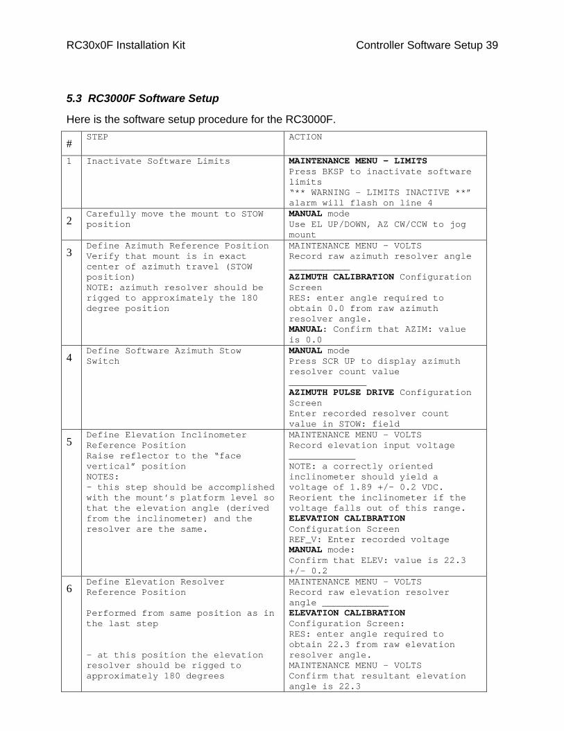
5.3 RC3000F Software Setup
Here is the software setup procedure for the RC3000F.
# STEP ACTION
1 Inactivate Software Limits MAINTENANCE MENU - LIMITS Press BKSP to inactivate software limits “** WARNING - LIMITS INACTIVE **” alarm will flash on line 4
2 Carefully move the mount to STOW position
MANUAL mode Use EL UP/DOWN, AZ CW/CCW to jog mount
3 Define Azimuth Reference Position Verify that mount is in exact center of azimuth travel (STOW position) NOTE: azimuth resolver should be rigged to approximately the 180 degree position
MAINTENANCE MENU - VOLTS Record raw azimuth resolver angle ___________ AZIMUTH CALIBRATION Configuration Screen RES: enter angle required to obtain 0.0 from raw azimuth resolver angle. MANUAL: Confirm that AZIM: value is 0.0
4 Define Software Azimuth Stow Switch
MANUAL mode Press SCR UP to display azimuth resolver count value ______________ AZIMUTH PULSE DRIVE Configuration Screen Enter recorded resolver count value in STOW: field
5 Define Elevation Inclinometer Reference Position Raise reflector to the “face vertical” position NOTES: - this step should be accomplished with the mount’s platform level so that the elevation angle (derived from the inclinometer) and the resolver are the same.
MAINTENANCE MENU - VOLTS Record elevation input voltage ____________ NOTE: a correctly oriented inclinometer should yield a voltage of 1.89 +/- 0.2 VDC. Reorient the inclinometer if the voltage falls out of this range. ELEVATION CALIBRATION Configuration Screen REF_V: Enter recorded voltage MANUAL mode: Confirm that ELEV: value is 22.3 +/- 0.2
6 Define Elevation Resolver Reference Position Performed from same position as in the last step - at this position the elevation resolver should be rigged to approximately 180 degrees
MAINTENANCE MENU - VOLTS Record raw elevation resolver angle ____________ ELEVATION CALIBRATION Configuration Screen: RES: enter angle required to obtain 22.3 from raw elevation resolver angle. MAINTENANCE MENU - VOLTS Confirm that resultant elevation angle is 22.3
RC30x0F Installation Kit Controller Software Setup 40
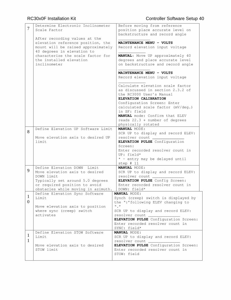
7 Determine Electronic Inclinometer Scale Factor After recording values at the elevation reference position, the mount will be raised approximately 40 degrees in elevation to characterize the scale factor for the installed elevation inclinometer
Before moving from reference position place accurate level on backstructure and record angle ______________ MAINTENANCE MENU - VOLTS Record elevation input voltage
______ ______MANUAL: Move UP approximately 40 degrees and place accurate level on backstructure and record angle ______________ MAINTENANCE MENU - VOLTS Record elevation input voltage ____________ Calculate elevation scale factor as discussed in section 2.3.2 of
ual the RC3000 User’s ManELEVATION CALIBRATION Configuration Screen: Enter calculated scale factor (mV/deg.) in SF: field MANUAL mode: Confirm that ELEV reads 22.3 + number of degrees physically rotated
8 Define Elevation UP Software Limit Move elevation axis to desired UP limit
MANUAL MODE: SCR UP to display and record ELEV:
______________ resolver count ELEVATION PULSE Configuration Screen: Enter recorded resolver count in UP: field* * - entry may be delayed until step # 11
9 Define Elevation DOWN Limit Move elevation axis to desired DOWN limit Typically set around 5.0 degrees or required position to avoid obstacles while moving in azimuth.
MANUAL MODE: SCR UP to display and record ELEV: resolver count ______________ ELEVATION PULSE Config Screen: Enter recorded resolver count in DOWN: field*
10
Define Elevation Sync Software Limit Move elevation axis to position where sync (creep) switch activates
MANUAL MODE: Synch (creep) switch is displayed by the “:”following ELEV changing to “.” SCR UP to display and record ELEV:
______________ resolver count ELEVATION PULSE Configuration Screen: Enter recorded resolver count in SYNC: field*
11
Define Elevation STOW Software Limit Move elevation axis to desired STOW limit
MANUAL MODE: SCR UP to display and record ELEV: resolver count ______________ ELEVATION PULSE Configuration Screen: Enter recorded resolver count in STOW: field

RC30x0F Installation Kit Controller Software Setup 41
12
Define Polarization Reference Position Move polarization axis to the position where the feed is horizontal/vertical (nearest to center of travel). This position is approximately where the center feed set screw is horizontal. - at this position the polarization resolver should be rigged to approximately 180 degrees
MAINTENANCE MENU - VOLTS Record raw polarization resolver angle ___________ POLARIZATION CALIBRATION Configuration Screen RES: enter angle required to obtain 0.0 from raw polarization resolver
angle.MANUAL Confirm that POL: value is 0.0
13
Confirm Polarization CW, CCW limits Move to CW and CCW limits
MANUAL MODE: Confirm that “CW” and “CCW” limits are displayed
14
Define Azimuth Clockwise Software Limit Move azimuth axis to clockwise limit
MANUAL MODE: Confirm that “CW” limit is triggered via limit switch SCR UP to display and record AZIM:
t ______________ resolver counAZIMUTH PULSE Configuration Screen: Enter recorded resolver count in CW: field
15
Define Azimuth Counter-Clockwise Software Limit Move azimuth axis to counter-clockwise limit
MANUAL MODE: Confirm that “CCW” limit is triggered via limit switch SCR UP to display and record AZIM: resolver count ______________ AZIMUTH PULSE Configuration Screen: Enter recorded resolver count in CCW: field
16
Activate Software Limits
MAINTENANCE MENU - LIMITS Press BKSP to activate limits Alarm on line 4 will disappear
17
Confirm all limit switch actions and indications Move azimuth, elevation and polarization axes through their entire range of movement.
MANUAL MODE: Verify sanity of all angle and limit indications
3.2.1 Manual Mode.
As an aid in calibration, the state of the elevation synch switch is displayed next to the elevation limit field. When the synch switch is activated “ELEV.” appears instead of the normal “ELEV:”.
AZIM: 0.0 STOW SS1: 50 MANUAL ELEV. -42.5 DOWN SAT:TELSTAR 402 POL: 30.0 V SPD:FAST CST <0-9>JOG ANTENNA <MODE>MENU 14:25:47

RC30x0F Installation Kit Controller Software Setup 42 Note also that when the elevation axis is below the DOWN limit position the displayed elevation angle is derived from the elevation resolver rather than the electronic inclinometer.

RC30x0F Installation Kit Azimuth and Elevation Motor/Brake 43
Appendix A Installation Kit Hardware The RC30x0 Installation Kit includes the hardware necessary to mount the azimuth and elevation motor/brake assemblies, mount the inclinometer enclosure, and to install the wiring harness. The installation kit hardware is RCI p/n FP-RC3KFHDKIT1.
The FP-RC3KFHDKIT1 kit is sub-divided as follows …
Interconnect Cabling Installation Kit- RCI p/n FB-3KFHDKIT1 -
Azimuth Motor Mounting - Kit FB-3KFHDKIT2
Elevation Motor Mounting Kit - FB-3KFHDKIT3
Inclinometer Enclosure Mounting Kit - FB-3KFHDKIT4
Polarization Installation - FB-3KFHDKIT5
A-1 RC30x0 Installation Kit Hardware Bill of Materials (RCI p/n FP-RC3KFHDKIT1)
Quan Manufacturer and P/N
RCI P/N Description
48” Hellermann Tyton CTP1120STD or Colflex 492.150
CDT-492.150 1 1/2" Convoluted Tubing. Place on the wiring harness where the wiring harness exits the pedestal. Overlap 4” with the 1” convoluted tubing coming from the feed boom.
2 Seese Machine SS-M4X5X15_KEY 4 mm x 5 mm x 15 mm stainless steel key for the azimuth and elevation motor shafts.
2 Panduit PLT5EH-Q0 NY-C-TIE_5X20 Cable Tie, 20 inch, black. Used for 1) securing elevation motor/brake cable to the elevation gear reducer, and 2) to attach the 1 ½” convoluted tubing and the 1” convoluted tubing together (with a 4” overlap) at the cable tie point in the pedestal enclosure.
12 Del-City 9629 NY-C-TIE 7_25” Cable Tie, 7.25 inch, black. Used to secure the 1 ½” convoluted tubing (quan 10) and to provide strain relief for the pol motor interface cable by attaching the cable to the body of the pol motor (quan 2).
1 Del-City 9722 NY-C-TIE 3_75” Cable Tie, 3.75 inch, black. Used around the pol motor cable conductors at the pol motor terminals.
1 ConXall Multi-Con-X 5 382 4SG 324
CX-53824SG324 Inline receptacle for pol limit switch connector. The Andrew pol limit switch wiring harness needs to be modified. The original harness passed through the pol motor conduit box.
3 Del-City 2505 NY-_312UV LOOM Loom Clamp, 5/16”, nylon. Used to secure the azimuth (2 places) and elevation (1 place) motor/brake cables.
RC30x0F Installation Kit Azimuth and Elevation Motor/Brake 44
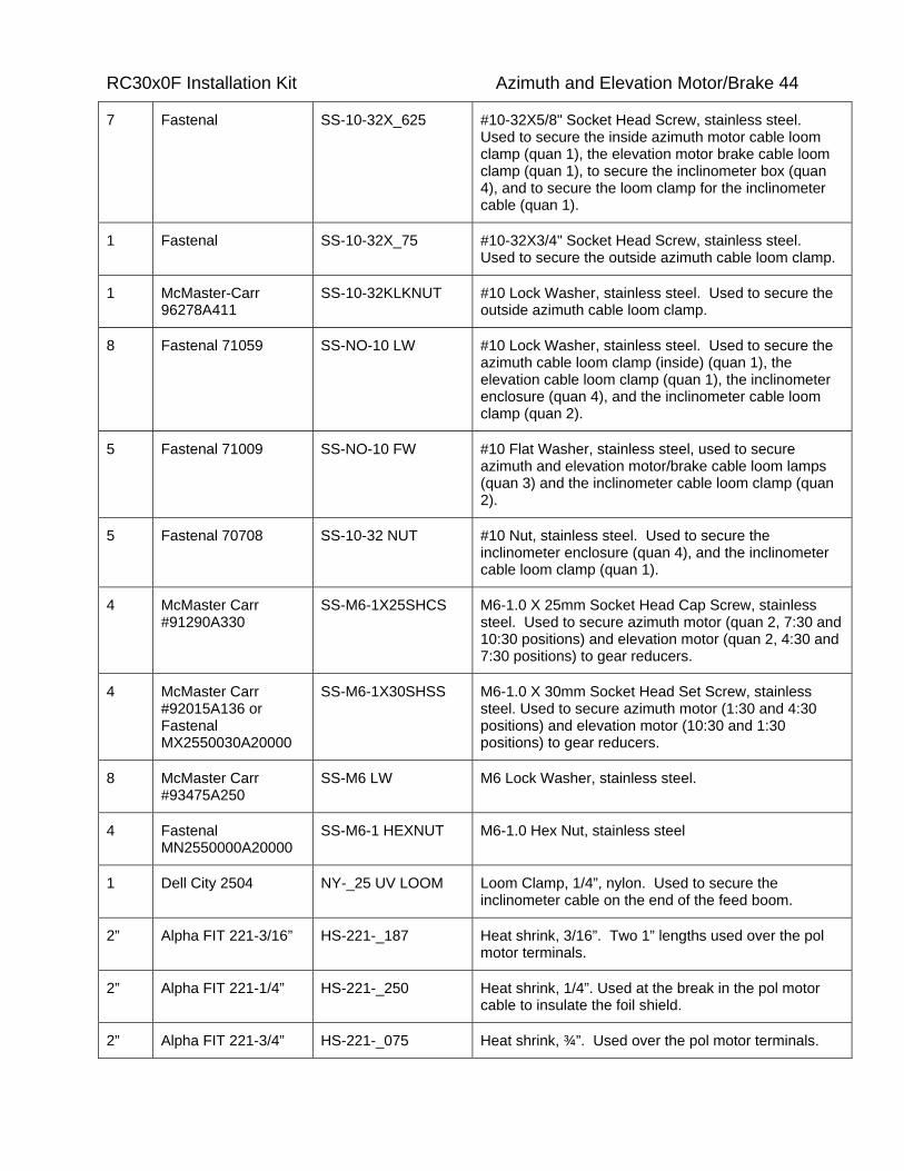
7 Fastenal SS-10-32X_625 #10-32X5/8" Socket Head Screw, stainless steel. Used to secure the inside azimuth motor cable loom clamp (quan 1), the elevation motor brake cable loom clamp (quan 1), to secure the inclinometer box (quan 4), and to secure the loom clamp for the inclinometer cable (quan 1).
1 Fastenal SS-10-32X_75 #10-32X3/4" Socket Head Screw, stainless steel. Used to secure the outside azimuth cable loom clamp.
1 McMaster-Carr 96278A411
SS-10-32KLKNUT #10 Lock Washer, stainless steel. Used to secure the outside azimuth cable loom clamp.
8 Fastenal 71059 SS-NO-10 LW #10 Lock Washer, stainless steel. Used to secure the azimuth cable loom clamp (inside) (quan 1), the elevation cable loom clamp (quan 1), the inclinometer enclosure (quan 4), and the inclinometer cable loom clamp (quan 2).
5 Fastenal 71009 SS-NO-10 FW #10 Flat Washer, stainless steel, used to secure azimuth and elevation motor/brake cable loom lamps (quan 3) and the inclinometer cable loom clamp (quan 2).
5 Fastenal 70708 SS-10-32 NUT #10 Nut, stainless steel. Used to secure the inclinometer enclosure (quan 4), and the inclinometer cable loom clamp (quan 1).
4 McMaster Carr #91290A330
SS-M6-1X25SHCS M6-1.0 X 25mm Socket Head Cap Screw, stainless steel. Used to secure azimuth motor (quan 2, 7:30 and 10:30 positions) and elevation motor (quan 2, 4:30 and 7:30 positions) to gear reducers.
4 McMaster Carr #92015A136 or Fastenal MX2550030A20000
SS-M6-1X30SHSS M6-1.0 X 30mm Socket Head Set Screw, stainless steel. Used to secure azimuth motor (1:30 and 4:30 positions) and elevation motor (10:30 and 1:30 positions) to gear reducers.
8 McMaster Carr #93475A250
SS-M6 LW M6 Lock Washer, stainless steel.
4 Fastenal MN2550000A20000
SS-M6-1 HEXNUT M6-1.0 Hex Nut, stainless steel
1 Dell City 2504 NY-_25 UV LOOM Loom Clamp, 1/4”, nylon. Used to secure the inclinometer cable on the end of the feed boom.
2” Alpha FIT 221-3/16” HS-221-_187 Heat shrink, 3/16”. Two 1” lengths used over the pol motor terminals.
2” Alpha FIT 221-1/4” HS-221-_250 Heat shrink, 1/4”. Used at the break in the pol motor cable to insulate the foil shield.
2” Alpha FIT 221-3/4” HS-221-_075 Heat shrink, ¾”. Used over the pol motor terminals.

RC30x0F Installation Kit Azimuth and Elevation Motor/Brake 45
Appendix B Azimuth and Elevation Motor/Brake The azimuth and elevation axis are powered by DC gear motors equipped with brakes. The RC30x0F Installation Kit includes azimuth and elevation gearmotor/brake/interconnect cable assemblies along with hardware to attach the assemblies and secure the interconnect cables. This chapters documents installation, assembly, disassembly, and testing of these integrated assemblies.
B-1 Azimuth and Elevation Motor/Brake Installation
This section covers the physical attachment of the motor/brake assemblies to the gear reducers and routing of the interconnect cables. Two bags of hardware are provided; one for the azimuth axis and the other for the elevation axis. The contents of those kits are described in sections 2.1.2 and 2.1.3.
B-1.1 Attaching the Motor/Brake Assemblies to the Gear Reducers
The azimuth and elevation motor brake assemblies are attached directly to mounting flanges on the gear reducers. Each gear reducer mounting flange is rectangular shaped with four tapped screw holes (M6-1.0) at the corners of the rectangular pattern. In the discussion that follows each corner of the rectangular motor mounting flanges are assigned a clock position as viewed looking into the gear reducer mounting flange. The upper right screw hole is 1:30, the lower right screw hole is 4:30, the upper left screw hole is 10:30, and the lower left screw hole is 7:30.
The mounting flange hole patterns are depicted on the Azimuth and Elevation Motor/Brake Detail drawing found in Section 2.2.3 (see the reference to the Brake End View, the upper assembly is for the azimuth axis). The drawing also depicts the fasteners used to attach the motors to the gear reducers (see items A, B, C, and D).
The azimuth and elevation motor attachment procedure is nearly identical. Here is the motor attachment procedure for the azimuth motor. Italicized text will be used to denote the steps in the sequence which are unique for the elevation axis relative to the azimuth axis.
1. Identify the 4 mm x 5 mm x 15 mm key. Place the key on the motor shaft and check the fit by mating the motor with the gear reducer. A fine file or emery paper can be used to polish the key to obtain a smooth fit.
2. Apply permanent thread lock compound to the two M6 studs.
3. For the azimuth axis thread the studs into the 1:30 and 4:30 positions. For the elevation axis, thread the studs into the 10:30 and 1:30 positions. Tighten to 9 ft-lbs.
4. Apply a thin layer of electronic grade silicon sealant to the gear reducer motor mounting flange.
5. With the key in position, slide the motor into position. Place a lockwasher over the socket head cap screws and thread into the gear reducer flange. Use a lockwasher and a nut on each of the studs. For the azimuth motor, it may not be possible to get a nut onto the stud in the 4:30 position. Secure all of the fasteners and then tighten to 9 ft-lbs.
RC30x0F Installation Kit Azimuth and Elevation Motor/Brake 46 6. Wipe off any excess silicone sealant.
B-1.2 Routing and Securing the Motor/Brake Cables to the Pedestal
The azimuth and elevation motor/brake interconnect cables are secured with nylon loom clamps and large cable ties. The placement of the hardware is described in the Azimuth and Elevation Motor/Brake Cable Routing Diagram of section 2.1.3.
Notice that for the azimuth axis, the loom clamp closest to the slot in the cover is placed inside the pedestal while the loom clamp furthest from the slot in the cover is located on the outside of the pedestal.

RC30x0F Installation Kit Azimuth and Elevation Motor/Brake 47
B.1.3 Azimuth and Elevation Motor/Brake Cable Routing Diagram

RC30x0F Installation Kit Azimuth and Elevation Motor/Brake 48
B-1.4 Azimuth Motor/Brake Installation Kit
The RC30x0F Installation Kit includes the hardware to attach the azimuth motor to the gear reducer and secure the azimuth motor/brake interconnect cable to the pedestal. These materials are contained in the Azimuth Motor Mounting Kit (RCI p/n FB-3KFHDKIT2).
Here are the contents of that kit …
Quan RCI P/N Description
1 SS-M4X5X15_KEY 4 mm x 5 mm x 15 mm stainless steel key for the azimuth motor shaft.
2 NY-_312UV LOOM Loom Clamp, 5/16”, nylon. Used to secure the azimuth motor/brake cable.
1 SS-10-32X_625 #10-32X5/8" Socket Head Screw, stainless steel. Used to secure the inside azimuth motor/brake cable loom clamp.
1 SS-10-32X_75 #10-32X3/4" Socket Head Screw, stainless steel. Used to secure the outside azimuth cable loom clamp.
1 SS-10-32KLKNUT #10 Lock Washer, stainless steel. Used to secure the outside azimuth cable loom clamp.
2 SS-NO-10 FW #10 Flat Washer, stainless steel, used to secure the azimuth motor/brake cable loom clamps.
1 SS-NO-10 LW #10 Lock Washer, stainless steel, used to secure the inside azimuth motor/brake cable loom clamps.
2 SS-M6-1X25SHCS M6-1.0 X 25mm Socket Head Cap Screw, stainless steel. Used to secure azimuth motor (7:30 and 10:30 positions) to gear reducer.
2 SS-M6-1X30SHSS M6-1.0 X 30mm Socket Head Set Screw, stainless steel. Used to attach azimuth motor (10:30 and 1:30 positions) to gear reducer.
4 SS-M6 LW M6 Lock Washer, stainless steel, for azimuth motor attachment.
2 SS-M6-1 HEXNUT M6-1.0 Hex Nut, stainless steel, for azimuth motor attachment.
1 A copy of this list.
Manufacturer’s part numbers for these items are included in the bill of materials for the FP-RC3KFHDKIT described in Appendix A.

RC30x0F Installation Kit Azimuth and Elevation Motor/Brake 49
B-1.5 Elevation Motor/Brake Installation Kit
The RC30x0F Installation Kit includes the hardware to attach the elevation motor to the gear reducer and secure the elevation motor/brake interconnect cable to the pedestal. These materials are contained in the Elevation Motor Mounting Kit (RCI p/n FB-3KFHDKIT3).
Here are the contents of that kit …
Quan RCI P/N Description
1 SS-M4X5X15_KEY 4 mm x 5 mm x 15 mm stainless steel key for the elevation motor shaft.
1 NY-C-TIE_5X20 Cable Tie, 20 inch, black. Used for securing elevation motor/brake cable to the elevation gear reducer.
1 NY-_312UV LOOM Loom Clamp, 5/16”, nylon. Used to secure the elevation motor/brake cable.
1 SS-10-32X_625 #10-32X5/8” Socket Head Screw, stainless steel. Used to secure the elevation motor/brake cable.
1 SS-NO-10 FW #10 Flat Washer, stainless steel, used to secure the elevation motor/brake cable loom clamp.
1 SS-NO-10 LW #10 Lock Washer, stainless steel, used to secure the elevation motor/brake cable loom clamp.
2 SS-M6-1X25SHCS M6-1.0 X 25mm Socket Head Cap Screw, stainless steel. Used to secure elevation motor (4:30 and 7:30 positions) to gear reducer.
2 SS-M6-1X30SHSS M6-1.0 X 30mm Socket Head Set Screw, stainless steel. Used to attach elevation motor (10:30 and 1:30 positions) to gear reducer.
4 SS-M6 LW M6 Lock Washer, stainless steel for elevation motor attachment.
2 SS-M6-1 HEXNUT M6-1.0 Hex Nut, stainless steel, for elevation motor attachment.
1 A copy of this list.
Manufacturer’s part numbers for these items are included in the bill of materials for the FP-RC3KFHDKIT described in Appendix A.

RC30x0F Installation Kit Azimuth and Elevation Motor/Brake 50
B-2 Azimuth and Elevation Motor/Brake Unit Assembly Procedures
The azimuth motor brake assembly is RCI p/n FB-3KFAZMB1. The elevation motor/brake assembly RCI p/n RCI p/n FB-3KFELMB1.
This procedure documents installation of the brake on the azimuth and elevation motors as well as the electrical connections between the integrated motor/brake assemblies and the controller interface cables (FB-3KFCBLAZMB1 is the azimuth interconnect cable, FB-3KFCBLELMB1 is the elevation interconnect cable). The assembly procedures are nearly identical for the azimuth and elevation motor/brake assemblies. The differences between the elevation and azimuth axis are noted in italicized text.
1. Identify, label, and check the motor (Azimuth motor Groschopp drawing # X4937-03, see section 2.2.1, Elevation motor Groschopp drawing # X4938-03, see section 2.2.2). The output shaft of the motor is offset with respect to the motor mounting flange (the motor output shaft is larger in diameter than the motor brake shaft). i) For the azimuth motor, use a marker to inscribe ‘AZ TOP’ on the motor mounting flange as depicted in the drawing. For the elevation motor, use a marker to inscribe ‘EL TOP’ on the motor mounting flange as depicted in the drawing. ii) Verify that the conduit box is oriented as outlined on the drawing and the motor shaft size is correct. The azimuth motor output shaft diameter is 0.4320” to 0.4325”. The elevation motor output shaft diameter is 0.5507 to 0.5512”. iii) Verify that the length of the motor output shaft is 1.150”. iv) Verify that the brake shaft diameter is 0.3745” to 0.3750”. Verify that the brake shaft length is 1.43”.
2. Remove the conduit box and apply sealant to the interior perimeter of the conduit box mounting base and the motor leads. Orient the motor so that the ‘TOP’ label is facing upward. i) Remove the upper conduit fitting. Install the LQT-3213 liquid tight strain relief. Use a 7/8” end wrench to tighten the strain relief. ii) Remove the motor conduit box. iii) Place a bead of electronic grade silicone sealant around three sides of the inside perimeter of the motor conduit enclosure mounting base to seal the gap between the mounting base and the motor. Do not place sealant along the bottom edge of the enclosure. This will allow water that makes it into the conduit box to drain. iv) Place silicon sealant around the motor lead wires.
Attach the brake base to the motor. Orient the motor so that the surface marked ‘TOP’ is facing upward and oriented horizontally. The brake base can be mounted three different ways. Mount the brake base so that the studs lie in a horizontal plane. When oriented in

RC30x0F Installation Kit Azimuth and Elevation Motor/Brake 51 3. this manner, the brake cover can be attached to the studs so that the brake cover weep
hole is at the lowest point in the brake cover. i) Spread a thin layer of electronic grade silicone sealant on the motor end cap where the brake mounts. Avoid getting sealant in the brake base screw mounting holes. ii) Attach the brake base to the motor with three #10-32x0.25” flat head screws. Use Loctite 262 permanent threadlocker on the screws.
4. Attach the brake hub to the motor shaft. The brake hub is equipped with two set screws, one of which passes through a keyway (the brake hub has a hexagonal outline). There is a flat on the motor brake shaft (see the MOTOR_BRAKES2 drawing). Orient the hub so that the set screw that does not pass through the brake hub keyway is perpendicular to the flat. A 1/16” hex key is used to tighten the set screws. i) Apply Loctite 262 permanent threadlocker to the brake hub set screws. ii) Use a 0.015” feeler gauge to set the clearance between the hub and the brake base. iii) Tighten the set screw that engages the flat (10 in-lb). As the set screw is tightened gently attempt to rotate the hub CW/CCW relative to the shaft to insure that the set screw is perpendicular to the flat. iv) Tighten the other set screw.
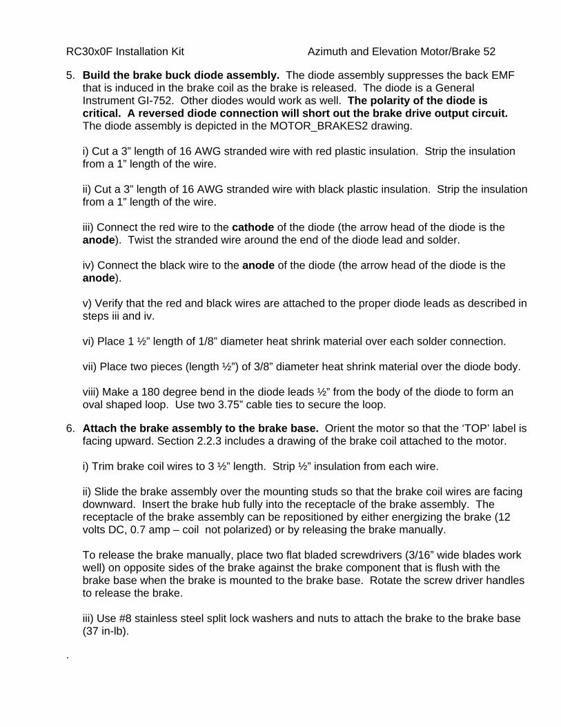
RC30x0F Installation Kit Azimuth and Elevation Motor/Brake 52
5. Build the brake buck diode assembly. The diode assembly suppresses the back EMF that is induced in the brake coil as the brake is released. The diode is a General Instrument GI-752. Other diodes would work as well. The polarity of the diode is critical. A reversed diode connection will short out the brake drive output circuit. The diode assembly is depicted in the MOTOR_BRAKES2 drawing. i) Cut a 3” length of 16 AWG stranded wire with red plastic insulation. Strip the insulation from a 1” length of the wire. ii) Cut a 3” length of 16 AWG stranded wire with black plastic insulation. Strip the insulation from a 1” length of the wire. iii) Connect the red wire to the cathode of the diode (the arrow head of the diode is the anode). Twist the stranded wire around the end of the diode lead and solder. iv) Connect the black wire to the anode of the diode (the arrow head of the diode is the anode). v) Verify that the red and black wires are attached to the proper diode leads as described in steps iii and iv. vi) Place 1 ½” length of 1/8” diameter heat shrink material over each solder connection. vii) Place two pieces (length ½”) of 3/8” diameter heat shrink material over the diode body. viii) Make a 180 degree bend in the diode leads ½” from the body of the diode to form an oval shaped loop. Use two 3.75” cable ties to secure the loop.
6. Attach the brake assembly to the brake base. Orient the motor so that the ‘TOP’ label is facing upward. Section 2.2.3 includes a drawing of the brake coil attached to the motor. i) Trim brake coil wires to 3 ½” length. Strip ½” insulation from each wire. ii) Slide the brake assembly over the mounting studs so that the brake coil wires are facing downward. Insert the brake hub fully into the receptacle of the brake assembly. The receptacle of the brake assembly can be repositioned by either energizing the brake (12 volts DC, 0.7 amp – coil not polarized) or by releasing the brake manually. To release the brake manually, place two flat bladed screwdrivers (3/16” wide blades work well) on opposite sides of the brake against the brake component that is flush with the brake base when the brake is mounted to the brake base. Rotate the screw driver handles to release the brake. iii) Use #8 stainless steel split lock washers and nuts to attach the brake to the brake base (37 in-lb).
.
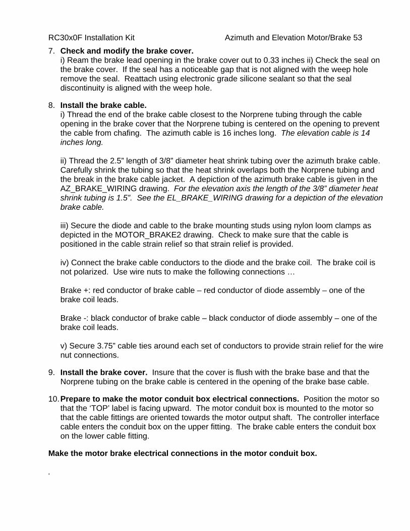
RC30x0F Installation Kit Azimuth and Elevation Motor/Brake 53 7. Check and modify the brake cover.
i) Ream the brake lead opening in the brake cover out to 0.33 inches ii) Check the seal on the brake cover. If the seal has a noticeable gap that is not aligned with the weep hole remove the seal. Reattach using electronic grade silicone sealant so that the seal discontinuity is aligned with the weep hole.
8. Install the brake cable. i) Thread the end of the brake cable closest to the Norprene tubing through the cable opening in the brake cover that the Norprene tubing is centered on the opening to prevent the cable from chafing. The azimuth cable is 16 inches long. The elevation cable is 14 inches long. ii) Thread the 2.5” length of 3/8” diameter heat shrink tubing over the azimuth brake cable. Carefully shrink the tubing so that the heat shrink overlaps both the Norprene tubing and the break in the brake cable jacket. A depiction of the azimuth brake cable is given in the AZ_BRAKE_WIRING drawing. For the elevation axis the length of the 3/8” diameter heat shrink tubing is 1.5”. See the EL_BRAKE_WIRING drawing for a depiction of the elevation brake cable. iii) Secure the diode and cable to the brake mounting studs using nylon loom clamps as depicted in the MOTOR_BRAKE2 drawing. Check to make sure that the cable is positioned in the cable strain relief so that strain relief is provided. iv) Connect the brake cable conductors to the diode and the brake coil. The brake coil is not polarized. Use wire nuts to make the following connections … Brake +: red conductor of brake cable – red conductor of diode assembly – one of the brake coil leads. Brake -: black conductor of brake cable – black conductor of diode assembly – one of the brake coil leads. v) Secure 3.75” cable ties around each set of conductors to provide strain relief for the wire nut connections.
9. Install the brake cover. Insure that the cover is flush with the brake base and that the Norprene tubing on the brake cable is centered in the opening of the brake base cable.
10. Prepare to make the motor conduit box electrical connections. Position the motor so that the ‘TOP’ label is facing upward. The motor conduit box is mounted to the motor so that the cable fittings are oriented towards the motor output shaft. The controller interface cable enters the conduit box on the upper fitting. The brake cable enters the conduit box on the lower cable fitting.
Make the motor brake electrical connections in the motor conduit box. .

RC30x0F Installation Kit Azimuth and Elevation Motor/Brake 54 11. i) Pull the controller interface cable through the ‘upper’ conduit box cable fitting. The
azimuth interface cable is FB-3KFCBLAZMB1. The elevation interface cable is FB-3KFCBLAZMB1ii) Pull the brake cable through the ‘lower’ conduit fitting. ii) Place 7 ¼” cable ties over the interface cable and brake cable jacketing material to provide strain relief. iii) Use set screw wire nuts to connect the interface cable conductors and drain wire to the motor leads, brake cable conductors, and brake cable drain wire as depicted on the Andrew ESA24SNG-LTE Cabling schematic. For the azimuth axis refer to the FB-3KFCBLAZMB1 cable assembly. For the elevation axis refer to the FB-3KFCBLELMB1 cable assembly on the schematic. Note that the connections for the azimuth and elevation axis are different. iv) Secure 3.75” cable ties around each pair of conductors to provide strain relief for the wire nut connections. v) Install the conduit box on the motor.
12. Tighten the conduit box cable connectors and secure the interconnect cable and brake cables. i) Tighten the conduit box cable fittings. Use a 19 mm wrench for the smaller conduit fitting and a 7/8” wrench for the larger fitting. ii) Attach two 11.25” cable ties together and secure around the body of the motor (on the output shaft side of the conduit box) to strain relief the brake cable. iii) Use a 20 inch cable tie to secure the interconnect cable to the body of the motor.
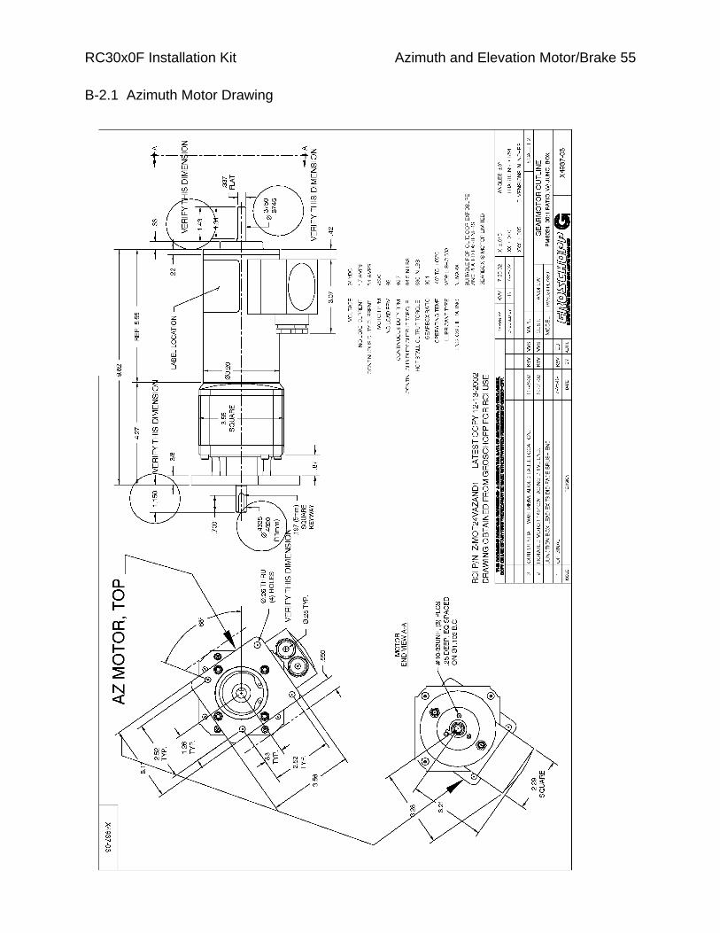
RC30x0F Installation Kit Azimuth and Elevation Motor/Brake 55
B-2.1 Azimuth Motor Drawing

B-2.2 Elevation Motor Drawing
RC30x0F Installation Kit Installation Kit Hardware 56

RC30x0F Installation Kit Installation Kit Hardware 57
B-2.3 Azimuth and Elevation Motor/Brake Detail
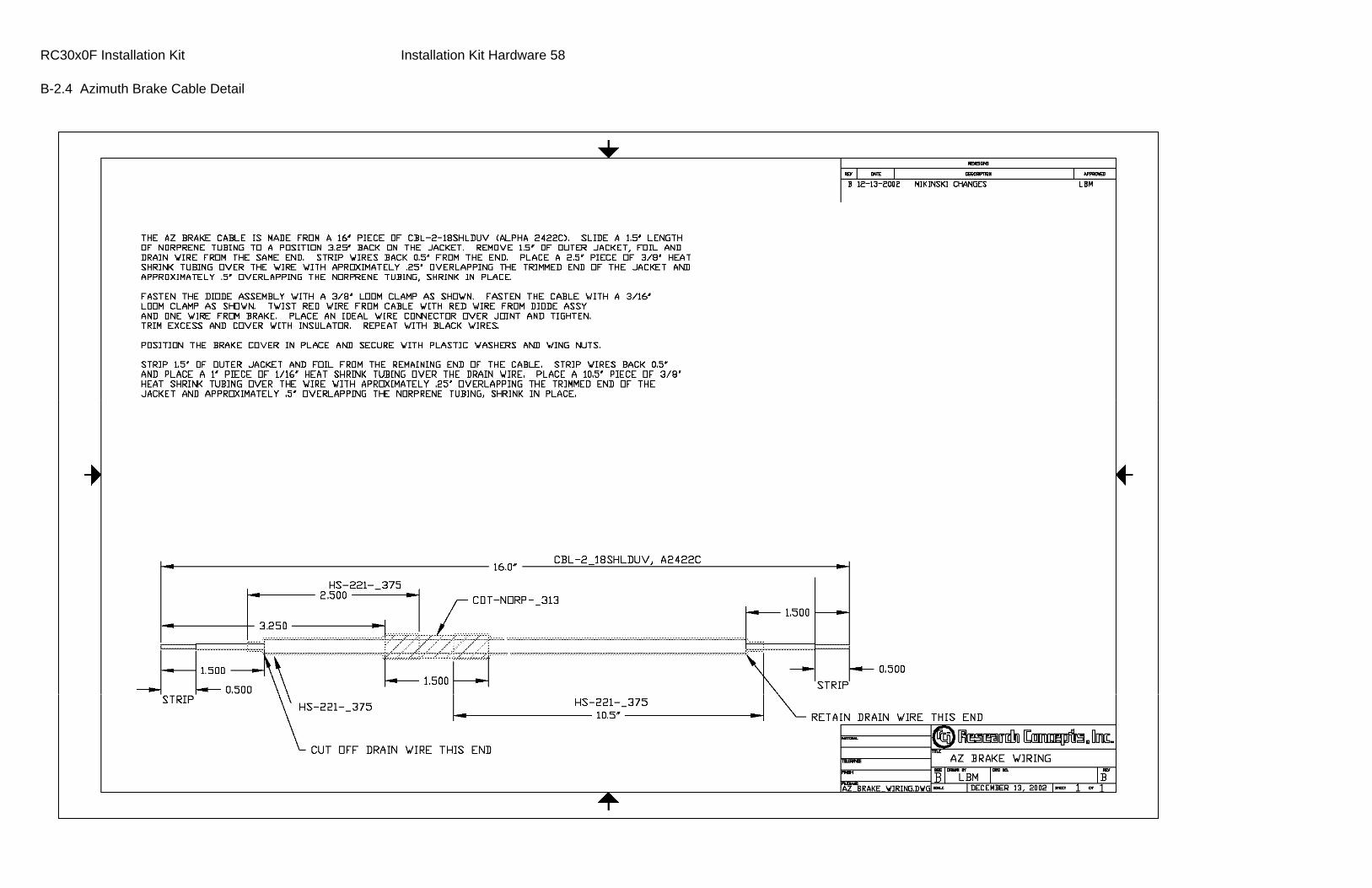
RC30x0F Installation Kit Installation Kit Hardware 58
B-2.4 Azimuth Brake Cable Detail

Installation Kit Hardware 59
B-2.5 Elevation Brake Cable Detail
RC30x0F Installation Kit

RC30x0F Installation Kit Azimuth and Elevation Motor/Brake 60
B-3 Azimuth and Elevation Motor/Brake Unit Disassembly Procedures
Disassembly of the azimuth and elevation motor brake assemblies is the reverse of the assembly procedure. During assembly, permanent thread locker is applied to the two set screws on the brake hub and the three screws that secure the brake base to the motor.
To remove fasteners secured with permanent threadlocker, heat the fastener with a heat gun or with a propane torch (very low flame).
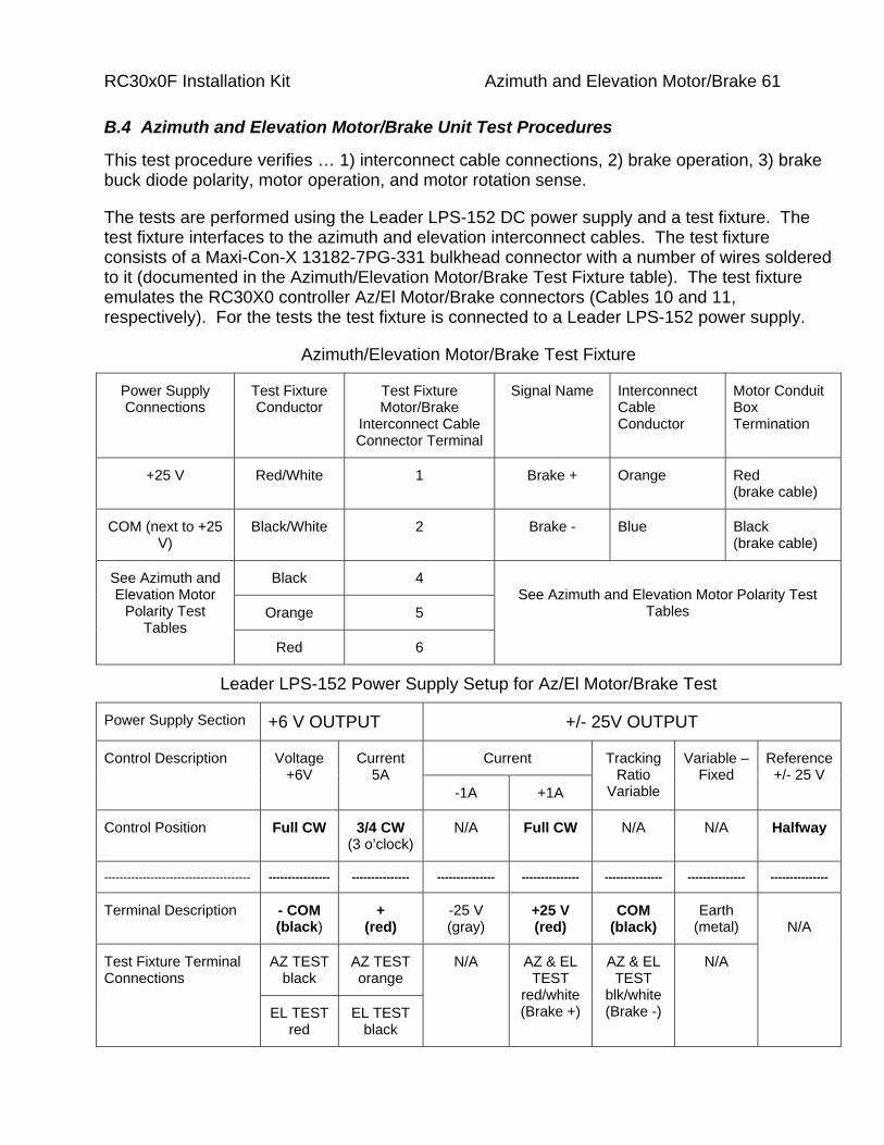
RC30x0F Installation Kit Azimuth and Elevation Motor/Brake 61
B.4 Azimuth and Elevation Motor/Brake Unit Test Procedures
This test procedure verifies … 1) interconnect cable connections, 2) brake operation, 3) brake buck diode polarity, motor operation, and motor rotation sense.
The tests are performed using the Leader LPS-152 DC power supply and a test fixture. The test fixture interfaces to the azimuth and elevation interconnect cables. The test fixture consists of a Maxi-Con-X 13182-7PG-331 bulkhead connector with a number of wires soldered to it (documented in the Azimuth/Elevation Motor/Brake Test Fixture table). The test fixture emulates the RC30X0 controller Az/El Motor/Brake connectors (Cables 10 and 11, respectively). For the tests the test fixture is connected to a Leader LPS-152 power supply.
Azimuth/Elevation Motor/Brake Test Fixture
Power Supply Connections
Test Fixture Conductor
Test Fixture Motor/Brake
Interconnect Cable Connector Terminal
Signal Name Interconnect Cable Conductor
Motor Conduit Box Termination
+25 V Red/White 1 Brake + Orange Red (brake cable)
COM (next to +25 V)
Black/White 2 Brake - Blue Black (brake cable)
Black 4
Orange 5
See Azimuth and Elevation Motor
Polarity Test Tables
Red 6
See Azimuth and Elevation Motor Polarity Test
Tables
Leader LPS-152 Power Supply Setup for Az/El Motor/Brake Test
Power Supply Section +6 V OUTPUT +/- 25V OUTPUT
Current Control Description Voltage +6V
Current 5A
-1A +1A
Tracking Ratio
Variable
Variable – Fixed
Reference+/- 25 V
Control Position Full CW 3/4 CW (3 o’clock)
N/A Full CW N/A N/A Halfway
-------------------------------------- ---------------- --------------- --------------- --------------- --------------- --------------- ---------------
Terminal Description - COM (black)
+ (red)
-25 V (gray)
+25 V (red)
COM (black)
Earth (metal)
AZ TEST black
AZ TESTorange
Test Fixture Terminal Connections
EL TEST red
EL TESTblack
N/A AZ & EL TEST
red/white(Brake +)
AZ & EL TEST
blk/white (Brake -)
N/A
N/A
RC30x0F Installation Kit Azimuth and Elevation Motor/Brake 62 B-4.1 Test Procedure
The power supply’s +6 volt output is used to power the motor (the motors have a nominal voltage rating of 24 VDC). The power supply’s +25 volt output is adjusted to approximately 12 volts and is used to power the brake coils. The power supply employs current limiting. The setup of the power supply is documented in the Leader LPS-152 Power Supply Setup for Az/El Motor/Brake Test table.
Configure the Power Supply – See the table labeled ‘Leader LPS-152 Power Supply Setup for Az/El Motor Polarity Test’ for the control positions associated with these settings. i) Insure that the power supply is switched off. ii) Set the power supply’s variable 6 volt DC output is set to a maximum voltage with a current limit set to approximately 3.75 amps CURRENT 5A control in the 3 o’clock position. iii) To test the brake, the power supply’s variable 25 volt DC output is set to approximately 12 volts with a current limit of approximately 1 amp (full CW deflection of the CURRENT 1A control).
Connect the Brake Leads of the Test Fixture to the Power Supply – Connect the Red/White lead of the test fixture to the power supply’s +25V terminal. Connect the Black/White lead of the test fixture to the power supply’s COM terminal (the one adjacent to the ‘+25V’ terminal).
Connect the Azimuth Motor/Brake Assembly to the Text Fixture i) Connect the Orange wire of the test fixture to the power supply’s +6V + terminal. Connect the Black wire of the test fixture to the power supply’s +6V – COM terminal. ii) Connect the azimuth motor/brake interconnect cable to the test fixture.
2.4.2 Test the Azimuth Motor/Brake Assembly
i) Switch ON the power supply. Listen for brake engagement. Verify that the azimuth motor output shaft turns CW. ii) Depress the power supply’s METER +6V button. Verify that the motor current is approximately 2.6 amps (read on the lower scale of the AMPERES meter). iii) Depress the power supply’s METER REFERENCE + 25V button. Verify that the brake current is approximately 0.7 amps (read on the upper scale of the AMPERES meter). iv) Remove the Red/White wire from the power supply’s +25 V (red) terminal. This will de-energize the brake. Verify that the motor stops turning. Switch the power supply OFF. v) Reconnect the Red/White wire to the power supply +25 V (red) terminal.
Connect the Elevation Motor/Brake Assembly to the Text Fixture

RC30x0F Installation Kit Azimuth and Elevation Motor/Brake 63 i) Connect the Black wire of the test fixture to the power supply’s +6V + terminal. Connect the Red wire of the test fixture to the power supply’s +6V – COM terminal. ii) Connect the azimuth motor/brake interconnect cable to the test fixture.
B-4.3 Test the Elevation Motor/Brake Assembly
i) Switch ON the power supply. Listen for brake engagement. Verify that the elevation motor output shaft turns CW. ii) Depress the power supply’s METER +6V button. Verify that the motor current is approximately 2.6 amps (read on the lower scale of the AMPERES meter). iii) Depress the power supply’s METER REFERENCE + 25V button. Verify that the brake current is approximately 0.7 amps (read on the upper scale of the AMPERES meter). iv) Remove the Red/White wire from the power supply’s +25 V (red) terminal. This will de-energize the brake. Verify that the motor stops turning. Switch the power supply OFF.
B-4.4 Troubleshooting
Refer to the Azimuth Motor Polarity Test Table and Elevation Motor Polarity Test Table i) If the Motor Turns in the Wrong Direction - Verify that the polarity of the voltage applied to the motor leads is correct. If it is not check the interconnect cable. If the proper voltage polarity is applied to the motor terminals, the motor may be miswired internally. Recode the motor leads (by covering the red motor lead with black heat shrink and the black motor lead with red heat shrink) and swap the interconnect cable connections so that the motor turns in the correct direction. ii) No Motor Movement – If the motor current is high the brake may not be fully released (the brake releases when the coil is energized). If there is no motor current there may be an open motor circuit, check connections. iii) Brake Current Too Low – The brake coil may be open circuited, check connections. iv) Motor Current Too High – If the brake current is low, the brake may not be released. If the brake current is normal the brake might not be fully disengaged or the motor may be defective. v) Brake Current Too High – The brake coil buck diode polarity may be reversed
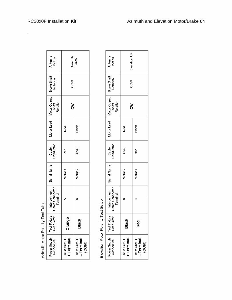
RC30x0F Installation Kit Azimuth and Elevation Motor/Brake 64
.

RC30x0F Installation Kit Azimuth and Elevation Motor/Brake 65
B-5 Azimuth Motor/Brake Unit Bill of Materials
Bill of Materials – RCI p/n FB-3KFAZMB1
Quan Manufacturer and P/N
RCI P/N Description
1 Groschopp PM8024-PL7330
Z-MOT24VAZAND1 Azimuth motor.
1 Rexnard/Stearns P/N 320441ASS0C2
Z-BRAKE-AND-1 Az/El Brake, 12 VDC, 10 watt with hub, cover, two #8 wing nuts, and two #8 nylon washers.
1 General Instrument GI 752
D-GIS752 Buck diode for brake coil.
16” Alpha 2432C CBL-2_18SHLDUV 2x18AWG shielded w/drain wire. Interfaces the brake coil to the interconnect cable splices at the motor conduit box.
3” Belden W-18G-RED 16 AWG stranded wire, red insulation, attached to cathode of diode. Strip 1” on the diode end, ½” on the brake coil end of the wire.
3” Belden W-18G-BLACK 16 AWG stranded wire, black insulation, attached to anode of diode. Strip 1” on the diode end, ½” on the brake coil end of the wire.
1.5” Norton Performance Plastics/Tygon A-60-G formulation p/n AFL000012
CDT-NORP-_313 Norprene Tubing, fitted over the brake cable where the cable passes through the brake cover to prevent chafing.
15” Alpha FIT 221-3/8” HS-221-_375 Heat shrink, 3/8”. Two pieces, 1/2” long, used over the brake diode assembly, 2 ½” length on the brake end of the brake cable, 9 ½” length on the motor end of the brake cable, 2” to insulate the shield at the break in the interconnect cable.
3” Alpha FIT 221-1/8” HS-221-_125 Heat shrink, 1/8”. Two pieces, 1 1/2” long, used over the brake diode leads.
2” Alpha FIT 221-1/16” HS-221-_062 Heat shrink, 1/16”, 1” length used to insulate the brake cable drain wire in the motor conduit box, 1” length over the drain wire of the interconnect cable.
1 Panduit PLT5EH-Q0 NY-C-TIE_5X20 Cable Tie, 20 inch, black. Used for securing the controller interconnect cable to the motor.
2 Del-City 9631-3 NY-C-TIE 11_25 Cable Tie, 11 inch, black. Used to secure the brake cable to the motor.
2 Del-City 9629 NY-C-TIE 7_25” Cable Tie, 7.25 inch, black. Used to prevent the cables that enter the motor conduit box from pulling back through the liquid tight strain reliefs.
9 Del-City 9722 NY-C-TIE 3_75” Cable Tie, 3.75 inch, black. Used to secure the loop

RC30x0F Installation Kit Azimuth and Elevation Motor/Brake 66 provides strain relief for the buck diode leads (quan 2) and to secure conductors that connected via the set screw wire nuts (quan 7).
1 Dell City 2503 NY-_187UV LOOM Loom Clamp, 3/16”, nylon. Used to secure the brake cable to the brake mounting stud.
1 Dell City 2506 NY-_375UV LOOM Loom Clamp, 3/8”, nylon. Used to secure the diode to the brake mounting stud.
3 Fastenal SS-10-32X_25 #10-32X1/4" Flat Head Screw, stainless steel. Used to secure brake base to the motor.
4 Fastenal 71057 SS-NO-8 LW #8 Lock Washer, stainless steel. Used to secure the brakes to the brake base (quan 2) and to secure the loom clamps to the brake base studs (quan 2).
4 Fastenal 71007 SS-NO-8 FW #8 Flat Washer, stainless steel, used to secure the loom clamps to the brake base studs.
4 Fastenal 70706 SS-8-32 NUT #8 Nut, stainless steel. Used to secure the brakes to the brake base (quan 2) and to secure the loom clamps to the brake base studs (quan 2).
7 Western Extralite 30-210
HD-SS-WIRE-CN Set screw wire nuts. Used to make the connections to the brake coil (quan 2) and for the connections in the motor conduit box (quan 5).
1 Sealcon CD-11AA-BK
LQT-3213 Liquid tight cable strain relief, PG 11 threads. Used in the motor conduit box (‘upper fitting’ when the motor is mounted) to strain relief the motor/brake interconnect cable.
B-6 Elevation Motor/Brake Unit Bill of Materials
Bill of Materials – RCI p/n FB-3KFELMB1
Quan Manufacturer and P/N
RCI P/N Description
1 Groschopp PM8024-PL7310
Z-MOT24VELAND1 Elevation motor.
1 Rexnard/Stearns P/N 320441ASS0C2
Z-BRAKE-AND-1 Az/El Brake, 12 VDC, 10 watt with hub, cover, two #8 wing nuts, and two #8 nylon washers.
1 General Instrument GI 752
D-GIS752 Buck diode for brake coil.
14” Alpha 2432C CBL-2_18SHLDUV Interfaces the brake coil to the interconnect cable splices at the motor conduit box.
3” Belden W-18G-RED 16 AWG stranded wire, red insulation, attached to cathode of diode. Strip 1” on the diode end, ½” on the brake coil end of the wire.
3” Belden W-18G-BLACK 16 AWG stranded wire, black insulation, attached to anode of diode. Strip 1” on the diode end, ½” on the

RC30x0F Installation Kit Azimuth and Elevation Motor/Brake 67 brake coil end of the wire.
1.5” Norton Performance Plastics/Tygon A-60-G formulation p/n AFL000012
CDT-NORP-_313 Norprene Tubing, fitted over the brake cable where the cable passes through the brake cover to prevent chafing.
13” Alpha FIT 221-3/8” HS-221-_375 Heat shrink, 3/8”. Two pieces, 1/2” long, used over the brake diode assembly, 1 ½” length on the brake end of the brake cable, 8 ¼” length on the motor end of the brake cable, 2” to insulate the shield at the break in the interconnect cable.
3” Alpha FIT 221-1/8” HS-221-_125 Heat shrink, 1/8”. Two pieces, 1 1/2” long, used over the brake diode leads.
2” Alpha FIT 221-1/16” HS-221-_062 Heat shrink, 1/16”, 1” length used to insulate the brake cable drain wire in the motor conduit box, 1” length over the drain wire of the interconnect cable.
1 Panduit PLT5EH-Q0 NY-C-TIE_5X20 Cable Tie, 20 inch, black. Used for securing the controller interconnect cable to the motor.
2 Del-City 9631-3 NY-C-TIE 11_25 Cable Tie, 11 inch, black. Used to secure the brake cable to the motor.
2 Del-City 9629 NY-C-TIE 7_25” Cable Tie, 7.25 inch, black. Used to prevent the cables that enter the motor conduit box from pulling back through the liquid tight strain reliefs.
9 Del-City 9722 NY-C-TIE 3_75” Cable Tie, 3.75 inch, black. Used to secure the loop provides strain relief for the buck diode leads (quan 2) and to secure conductors that connected via the set screw wire nuts (quan 7).
1 Dell City 2503 NY-_187UV LOOM Loom Clamp, 3/16”, nylon. Used to secure the brake cable to the brake mounting stud.
1 Dell City 2506 NY-_375UV LOOM Loom Clamp, 3/8”, nylon. Used to secure the diode to the brake mounting stud.
3 Fastenal SS-10-32X_25 #10-32X1/4" Flat Head Screw, stainless steel. Used to secure brake base to the motor.
4 Fastenal 71057 SS-NO-8 LW #8 Lock Washer, stainless steel. Used to secure the brakes to the brake base (quan 2) and to secure the loom clamps to the brake base studs (quan 2).
4 Fastenal 71007 SS-NO-8 FW #8 Flat Washer, stainless steel, used to secure the loom clamps to the brake base studs.
4 Fastenal 70706 SS-8-32 NUT #8 Nut, stainless steel. Used to secure the brakes to the brake base (quan 2) and to secure the loom clamps to the brake base studs (quan 2).
7 McMaster-Carr 30-210
HD-SS-WIRE-CN Set screw wire nuts. Used to make the connections to the brake coil (quan 2) and for the connections in the motor conduit box (quan 5).

RC30x0F Installation Kit Azimuth and Elevation Motor/Brake 68
1 Sealcon CD-11AA-BK
LQT-3213 Liquid tight cable strain relief, PG 11 threads. Used in the motor conduit box (‘upper fitting’ when the motor is mounted) to strain relief the motor/brake interconnect cable.

RC30x0F Installation Kit Revision History 69
Revision History 04.20.10 Updated TOC & Added Revision History
05.03.10 Updated Pol Motor information.