operating manual installation guide - edbro technical...
TRANSCRIPT

MOUNTTHIS
WAY UP
Model: TINCPower Input: DC 12-24vSerial No: ETINC 00-00-00Made in United Kingdom
FRONT
VEHICLE ANGLE º
INCLINOMETER
VEHICLE ANGLE º
INCLINOMETER
“BEEEEEEEEEEEEEP”
VEHICLE ANGLE º
INCLINOMETER
“BEEP, BEEP, BEEP”
VEHICLE ANGLE º
INCLINOMETER
Operating Manual
1. Power On/Power Off
1.1 The Inclinometer is powered by the ignition switched power for the vehicle. When the ignition power to the vehicle is on the display will power up in standby mode.
1.2 Pressing the Standby Button will wake the system from standby. Each time the system comes out of standby the display will perform a quick self test by sounding the buzzer and lighting all the LED indicators. The current vehicle angle will then be displayed in degrees along with the direction of vehicle lean.
1.3 To put the system back into standby mode, press and hold the standby button for two seconds.
2. Operation
2.1 The Inclinometer is designed to display the vehicle or trailers roll angle (i.e. L/R lean) and give an audio/visual alarm when an unsafe angle is reached to prevent rollover. In normal op-eration the current angle of the vehicle or trailer is displayed on the in cab display unit along with the direction of lean (left or right). If the angle is under the preset alarm limit then raising of the tipper body can commence as normal. USUAL SAFETY PROCEDURES SHOULD STILL BE FOLLOWED.
2.2 If the angle gets to 0.3º below the preset alarm limit then a warning will be given to indicate that the vehicle or trailer is close to an unsafe angle. The display will flash and a slow audible ‘beep’ tone will be given.
2.3 When the vehicle or trailer reaches or exceeds the preset alarm limit then a fast alarm tone is given and the display will flash rapidly. At this point the system will prevent the tipper body from being raised any further by disengaging the tipper control valve. THE TIPPER BODY SHOULD BE IMMEDIATELY LOWERED AND THEN THE VEHICLE SHOULD BE REPOSITIONED ONTO GROUND WHICH IS BELOW THE SAFE TIPPING LIMIT.
2.4 When tipping is complete and the body has been fully lowered, the display should be returned to standby mode by pressing and holding the standby button for 2 seconds.
IMPORTANT! - THE INCLINOMETER SYSTEM WILL PREVENT THE TIPPER BODY FROM BEING RAISED UNDER THE FOLLOWING CONDITIONS: • DISPLAY IS IN STANDBY • ANGLE IS ABOVE THE PRESET ALARM LIMIT • AN ERROR HAS BEEN DETECTED (INDICATED BY ‘EE’ ON THE DISPLAY
3. Error detection
3.1 If the Inclinometer display becomes disconnected from the Sensor Module or does not receive any angle data from more than 2 seconds then it will display an error message. This is indicated by ‘EE’ on the display and a constant audible buzzer tone .
Note: If the Suzi cable connecting the tractor to trailer is disconnected the display will show an error message. Reconnect the Suzi for correct operation.
Power OnStandby Indicator
Angle & Direction L.E.D will flash when the angle is within 0.3° of the preset limit. It will flash rapidly if the limit is reached or exceeded.
‘EE’ Indicates that an error has been detected. The display will flash and a continuous alarm tone will be given.The Inclinometer will NOT allow the Tipper body to be raised if an error is detected.
4. Setting the alarm limit
4.1 Using the supplied management key, swipe the key across the management mode key area within 5 seconds of turning the vehicles ignition power on.
4.2 A single audible tone will be given to indicate that the display is now in management mode.
4.3 The left and right direction LED’s will now light alternately. This allows setup of the sensor orientation. The sensor measures the angle of the chassis in the roll axis i.e. left and right lean, therefore to correctly display the direction of lean the display must be programmed with the direction that the sensor module is facing. In most cases the front of the sensor should be mounted so that it is pointing towards the drivers cab. Sometimes due to space restrictions it may be necessary to mount the sensor so that the front is pointing towards the rear of the ve-hicle. Check which direction the sensor is facing and select the orientation setting as follows.
To selection the orientation setting press the standby button once when the required LED is lit.
4.4 The display will now indicate the current alarm limit angle. The alarm limit can now be adjusted by pressing the standby button . Pressing the button will increment the angle in 0.1º increments. The alarm limit can be set between 0.5º to 9.9 º and the system is factory default set to 3.0º .
4.5 Once the required alarm limit angle is indicated on the display, swipe the management key over the management mode key area to store the setting and return the system to standby mode. CAUTION! - THE INCLINOMETER DISPLAY IS FACTORY SET TO 3º. IT IS NOT RECOMMENDED THAT THE ALARM LIMIT IS SET GREATER THAN 3º UNLESS YOU ARE CERTAIN THAT IT IS SAFE TO DO SO AND THAT THE VEHICLE/TRAILER IS CAPABLE OF OPERATING AT THAT CAMBER ANGLE. THIS SHOULD BE CONFIRMED BY THE VEHICLE/TRAILER MANUFACTURER. FAILURE TO DO SO COULD RESULT IN AN OVERTURN!
CAUTION! - DO NOT PLACE MAGNETS OR MAGNETIC OBJECTS NEAR THE INCLINOMETER SENSOR WHILE IT IS POWERED UP AS THIS MAY DAMAGE THE SENSOR OR CAUSE LOSS OF CALIBRATION.
4.6 Overriding the Inclinometer
In certain situations it may be necessary to temporarily override the Inclinometer system, such as when a tractor is pulling a trailer that is not fitted with an Inclinometer sensor. The Inclinom-eter can only be overridden when it is NOT receiving data from the Inclinometer sensor. i.e. When the error message ‘EE’ is displayed on the in cab unit.
To override the inclinometer:1. Power the system up and bring it out of standby mode by briefly pressing the standby button. 2. If the trailer has been disconnected the the error message ‘EE’ should be dis played after a short delay.3. Within 10 seconds of ‘EE’ being displayed hold the management key against the key area whist holding down the standby button. 4. Hold the key in position as well the holding down the standby button down for at least 5 seconds until ‘Or’ is displayed. 5. The inclinometer system is now in override and the tipper cut-off valve will be permanently held in the open position*.
CAUTION! Great care must be taken when using the Inclinometer in override mode as the vehicle WILL NOT BE PROTECTED AGAIST POTENTIAL ROLLOVER as the tipper body can be raised irrespective of the chassis angle.
NOTE: When in override mode the display cannot be put into standby *Override mode will be cancelled each time power to the Inclinometer is switch off. I.e. When the vehicles ignition is switch off. The Inclinometer can only be overridden when there is no inclinometer sensor connected to the display.
Management Mode Key Area
Management Key (supplied in kit)
Within 5 seconds of ignition power on
Front of Sensor facing cab Select RIGHT
Front of Sensor facing away from cab Select LEFT
MUB020001EN_REV01_11-2015
Installation Guide
5. Fitting the sensor
5.1 The sensor is fitted to the rear most cross member of the trailer or chassis using two M4x20 Bolts. Holes can be either drilled and tapped to M4 or fitted using the supplied M4 Nyloc Nuts. Mount the sensor so that the front of the sensor is facing towards the drivers cab. Occasionally it may not be possible to mount the sensor so that is faces the cab due to space restrictions. If this is the case then the sensor can me mounted to the opposite side of the cross member so that it faces away from the cab towards the rear of the vehicle/trailer, however in this configuration the sensor orientation must be altered on the display unit. See section 4.3. It is very import to mount the sensor so that it is exactly parallel with the cross member. It is recommended that an accurate angle measurement is taken of the chassis and that the sensor mounted so as to be level with it. e.g. if the angle of the chassis was 1º to the left then the sensor would be mounted 1º to the left meaning that the sensor and chassis are parallel. This can also be achieved by accurately measuring the distance from the top of the cross member so that distance ‘A’ and ‘B’ are exactly the same.
5.2 By default the Inclinometer sensor is calibrated to read 0º at true 0º just as a bubble level or Plumb bob would read 0º. The display is also factory default set to read left/right with the front of the sensor facing towards the front of the display.
6. Routing the cables ***(for Trailer Inclinometer Kit)
6.1 Connect the 4 pin plug on the trailer cable to the sensor making sure that it is tight and secure.
6.2 Fix the trailer cable up the length of the trailer using the cables ties provided.
6.3 Mount the SUZI connectors of the tractor and trailer cable
6.4 Route the tractor cable along the tractor chassis and into the driver cab. Be sure to protect the cable from engine heat or damage.
6.5 Rigid Inclinometer Kit Only. The Rigid Tipper version of the Inclinometer kit is only supplied with a single 20m cable that connects the inclinometer sensor to the in cab display. This cable should be connected to the sensor making sure it is tight and secure. Then fix the cable up the length of the chassis and into the drivers cab using the cable ties provided. Be sure to protect the cable from engine heat or damage.
6.6 The cable coming from the sensor unit plugs into 4 pin port on the rear of the in cab display. (on Trailer and Rigid Inclinometer Kits)
7. Mounting the display
7.1 The display unit should be mounting inside the drivers cab so that it can easily be seen and reached from the drivers position. It should be mounted in a safe position where it does not interfere with normal driving and does not distract the driver or obscure the drivers line of sight. A 3M adhesive pad is provided on the base of the mounting bracket but for textured and curved surfaces it is recommended that the bracket is fixed using the two 2.9x9.5 self tapping screws provided.
7.2 Connect the power/valve cable into the 6 pin connector on the rear of the display unit then connect the 4 pin connection from the trailer cable.
7.3 Connect the cable marked ‘power’ to the vehicles ignition switched power feed. Note: BLACK = GROUND (0v) RED= +v DC 12 to 24v.
Electrical installation should only be carried out by a qualified technician. The system must be fused - 1 Amp Fuse and Fused holder supplied.
8. Installing the tipper cut of valve
8.1 Route the cable marked ‘Valve’ around the cab to a point where there is access to the tipper control air pipes. (Normally found at the rear of the tipper control handle). Be sure to protect the cable from heat or damage.
8.2 The tipper cut-off valve is intended to prevent the tipper body from being raised when the system is in an alarm condition. This prevents the tippers centre of gravity (CG) from being raised which may prevent the trailer from overturning.
MOUNTTHIS
WAY UP
Model: TINCPower Input: DC 12-24vSerial No: ETINC 00-00-00Made in United Kingdom
A BRear cross member or trailer/ chassis
0°
Drill and tap to M4
Valve operation and connections
8.3 The tipper cut-off valve is supplied with 6mm push-fit pneumatic fittings (most tipper kits are supplied with 6mm hoses). The valve should be installed into the ‘TIP’ airline going from the tipper control handle to the tipper system, i.e. the air hose which supplies air pressure when the tipper control is in the raise position.
8.4 Connect the cable marked ‘Valve’ from the display unit to the push fit connectors on the valve. Note: The valve is NOT polarised.
9. Trouble Shooting
9.1 There is no power to the system? • The system is normally powered by the vehicles ignition switched power supply. The ignition must be in the POWER ON position. On power up the system will automatically go into standby mode which is indicated on the display. • Check that all the cable connections to the display are plugged in and secure and that the power cable is correctly linked into the vehicles power system. • The fuse to the system may have blown, check the 1A fuse located at the end of the power lead usually under the dash where the power to the system has been picked up.
9.2 The display shows that it is safe to tip but the tipper body will not raise? • Check that all the cable connections to the display are plugged in and secure and are undamaged. • Check that the tipper cut off valve is installed correctly. The valve is marked ‘1’ for input and ‘2’ for output. Also make sure that the valve is installed in the correct air line. See section 8. • Occasionally excessive dirt and moisture in the airline may cause the valve to stick. Try cleaning the valve and pushing the override button to free the valve shuttle. If the valve fails at any point it must be replaced with a new one even if cleaning it seems to cure the problem.
9.3 The system is alarming but the vehicle/trailer is on level ground? • The system will go into an alarm state if the chassis angle is equal to or greater than the maximum tipping angle which is set on the display. The system is factory default set to 3º e.g. if the side to side lean of the chassis is equal to or greater than 3.0º then the alarm will sound and tipping will stop. Note: A warning will also be given when the angle is 0.3º less than the alarm limit but tipping is not affected.
If the system is alarming and displaying ‘EE’ then an error has been detected. See section 3.
10. Maintenance 10.1 There are NO USER SERVICEABLE PARTS in either the display or sensor unit. Providing the system has been correctly installed it should require minimal maintenance. The connector plugs and cables on the exterior of the vehicle should be regularly checked for cor-rosion, dirt and moisture ingress. All parts may be cleaned using a soft damp cloth. DO NOT use detergents, abrasives, solvents or alcohol. Prevent moisture and dirt build up around all connections. DO NOT allow liquid to enter the display unit. If any liquid is split onto the display unit it should be switched off immediately and thoroughly dried with a clean cloth.
WARNING! DO NOT USE HIGH PRESSURE WASHERS OR WATER JETS ON ANY PART OF THE INCLINOMETER SYSTEM.
Power connected NOT POLARISED
Not Used
Override Button
‘2’ Air OUT‘1’ Air IN
To Tipper System
Rear of TipperControl Handle
Valve Power Connection - NOT POLARISED
NOT USED
Pneumatic Connections: 1/4” BSP Thread 6mm Fitting Electrical Connections: 6.5mm Push on Connector
Clé de contrôle (Fourni dans le kit)
MOUNTTHIS
WAY UP
Model: TINCPower Input: DC 12-24vSerial No: ETINC 00-00-00Made in United Kingdom
AVANT
VEHICLE ANGLE º
INCLINOMETER
VEHICLE ANGLE º
INCLINOMETER
“BEEEEEEEEEEEEEP”
VEHICLE ANGLE º
INCLINOMETER
“BEEP, BEEP, BEEP”
VEHICLE ANGLE º
INCLINOMETER
Manuel d’utilisation
1. Allumage
1.1 L’inclinomètre est mis en route par la mise sous tension du véhicule. Lorsque le véhicule est démarré, le moniteur s’allume en mode veille.
1.2 Presser le bouton de veille remet en route le système. A chaque fois que le système sort de sa veille, un rapide test automatique sera effectué pour vérifier les alarmes sonores et les indicateurs lumineux. L’angle actuel du véhicule est affiché ainsi que sa direction.
1.3 Pour remettre le système en veille, restez appuyé sur le bouton de veille pendant deux secondes.
2. Fonctionnement
2.1 L’inclinomètre est conçu pour afficher l’angle et la direction de l’inclinaison, droite ou gauche, du véhicule ou de la remorque et informer au moyen d’une alerte sonore et visuelle lorsqu’un angle dangereux est atteint afin de prévenir d’un renversement latéral. Dans un fonctionnement normal, l’angle d’inclinaison du véhicule ou de la remorque ainsi que la direc-tion de l’inclinaison (flèche droite ou gauche) sont affichés sur l’écran du moniteur. Si l’angle est en dessous du seuil d’alarme alors le levage de la benne peut se poursuivre.
LES PROCEDURES DE SECURITE DOIVENT TOUJOURS ETRE SUIVIES
2.2 Si l’angle arrive à 0.3º en dessous du seuil d’alarme réglé, alors un avertissement indique que le véhicule ou la remorque est proche de l’inclinaison maximale. L’écran affiche l’alerte accompagnée d’un avertissement sonore lent.
2.3 Lorsque le véhicule ou la remorque atteint ou dépasse le seuil d’alarme, une rapide tonal-ité et des signaux lumineux avertissent l’utilisateur.
2.4 Lorsque le levage est terminé et que tout a été déchargé, l’écran d’affichage doit être remis en veille en appuyant deux secondes sur le bouton “ Veille”. IMPORTANT ! – LE PROGRAMME DE L’INCLINOMETRE EMPECHE LE LEVAGE DE LA BENNE DANS LES CONDITIONS SUIVANTES : • AFFICHAGE EN VEILLE • INCLINAISON SUPERIEURE AU SEUIL D’ALARME REGLEE • UNE ERREUR A ETE DETECTEE (INDIQUEE PAR ‘EE’ SUR L’ECRAN)
3. Détection d’erreur
3.1 Si le boitier d’affichage de l’inclinomètre est déconnecté du capteur ou s’il ne reçoit aucune information d’inclinaison pendant plus de 2 secondes alors il affiche un message d’erreur. Cette erreur sera indiquée par ‘EE’ sur l’écran et par une tonalité constante.
Note: Si le câble Suzi connectant le camion à la remorque est déconnecté, le boitier affiche un message d’erreur. Reconnecter le pour un fonctionnement correct.
Témoin d’allum-age et de veille
Les LED de l’angle et de la direction clignotent lentement lorsque l’angle atteint est de 0.3° en dessous de l’angle limite. En cas d’atteinte ou de dépassement de celui-ci les LED clignotent rapidement.
‘EE’ indique qu’une erreur a été détectée. L’affichage clignote et une alarme retentit. L’inclinomètre empêchera le levage de la benne si une erreur est détectée.
4. Configuration de la limite de l’alarme
4.1 Faire glisser la clé de gestion le long de la zone dédiée (voir ci-dessous) dans les 5 sec-ondes suivant le démarrage du véhicule.
4.2 Un avertissement sonore est émis afin d’indiquer que l’écran est maintenant en mode gestion.
4.3 Les LED de direction droite et gauche sont désormais allumées alternativement. Ceci permet l’installation du capteur d’orientation. Le capteur mesure l’angle du châssis dans l’axe de roulis : Ex. Inclinaison gauche ou droite. Afin d’afficher correctement la direction d’inclinai-son, l’affichage doit être programmé avec la bonne direction. Dans la plupart des cas, l’avant du capteur doit être monté de sorte qu’il soit dirigé vers la cabine de conduite (flèche du capteur en direction de la cabine).A cause du manque d’espace, il est parfois nécessaire de monter le capteur de telle sorte que la face avant soit orientée vers l’arrière du véhicule (flèche du capteur en direction de l’arrière du véhicule). Vérifier la direction dans laquelle le capteur est orienté et sélectionner le réglage de l’orientation de la manière suivante :
Pour choisir le réglage de l’orientation, appuyez sur le bouton de veille dès que la LED requi-se (à gauche ou à droite) est allumée
4.4 L’affichage indique maintenant l’angle limite actuel de l’alarme. La limite de l’alarme peut maintenant être réglée en appuyant sur le bouton de veille. Appuyer sur le bouton incré-mente l’angle de 0,1º. La limite de l’alarme peut être réglée entre 0.5º et 9.9 º. Le système est par défaut réglé en usine pour 3.0º
4.5 Une fois que l’angle limite de l’alarme requis est indiqué sur l’affichage, glisser la clé de gestion sur la zone dédiée afin d’enregistrer les modifications et retourner en mode veille.
ATTENTION! – L’INCLINOMETRE EST REGLE PAR DEFAUT EN PARAMETRE D’USINE POUR 3.0 DEGRES. IL N’EST PAS RECOMMENDE DE REGLER L’ALARME DE LA LIMITE A PLUS DE 3º A MOINS D’ETRE CERTAIN QUE CELA EST SANS DANGER ET QUE LE VEHICULE/REMORQUE PEUT ETRE UTILISE AVEC CET ANGLE D’INCLINAISON. CELA DOIT ETRE CONFIRME PAR LE FAB RICANT DU VEHICULE/REMORQUE. NE PAS RESPECTER CES CONSIGNES POURRAIT CONDUIRE A UN RENVERSEMENT DU VEHICULE!
ATTENTION! NE PAS PLACER D’AIMANT OU TOUT OBJET AIMENTE PRES DES CAPTEURS DE L’INCLINOMETRE TANT QUE CELUI-CI EST ALLUME. CELA POURRAIT ENDOMMAGER LES CAPTEURS ET CAUSER UNE PERTE DES REGLAGES DE CALIBRAGE.
4.6 Réinitialision de l’inclinomètre
Dans certaines situations il peut être nécessaire de réinitialiser temporairement l’inclinomètre, dans le cas où un camion tire une remorque qui n’est pas équipé d’un capteur d’inclinaison. L’inclinomètre ne peut être réinitialisé que s’il ne reçoit pas de données du capteur d’inclinai-son. C’est-à-dire quand le message d’erreur « EE » est affiché sur le moniteur.Pour réinitialiser l’inclinomètre :1. Allumer le système en le sortant du mode veille à l’aide du bouton de veille.2. Si la remorque a été déconnectée le message d’erreur « EE » devrait apparaitre rapidement.3. Dans les 10 secondes où le message « EE » est affiché, tenez la clef de contrôle contre la zone de contrôle de la clef tandis que vous maintenez le bouton de veille enfoncé.4. Garder la clef en position et le bouton veille enfoncé au minimum 5 secondes jusqu’à ce que le message « Or » apparaisse sur le moniteur.5. L inclinomètre est maintenant réinitialisée et la valve de sécurité de la remorque sera maintenue en position ouverte*.ATTENTION ! Une grande attention doit être apportée quand l’inclinomètre est utilisé en mode « réinitialiser » car le véhicule NE SERA PAS PROTEGE CONTRE UN POTENTIEL RENVERSEMENT car la benne peut être levée indépendamment de l’angle entre le châssis et la benne. REMARQUE : Lors de l’utilisation de la réinitialisation le moniteur ne peut être mis en mode veille. *Le mode réinitialisation sera annulé à chaque fois que l’inclinomètre sera éteint. C’est-à-dire quand le véhicule est éteint. L’inclinomètre ne peut être réinitialisé que lorsqu’aucun capteur n’est connecté au moniteur.
Avant du capteur face á la cabine Sélectionner DROITE
Avant du capteur opposé à la cabine Sélectionner GAUCHE
Guide d’installation
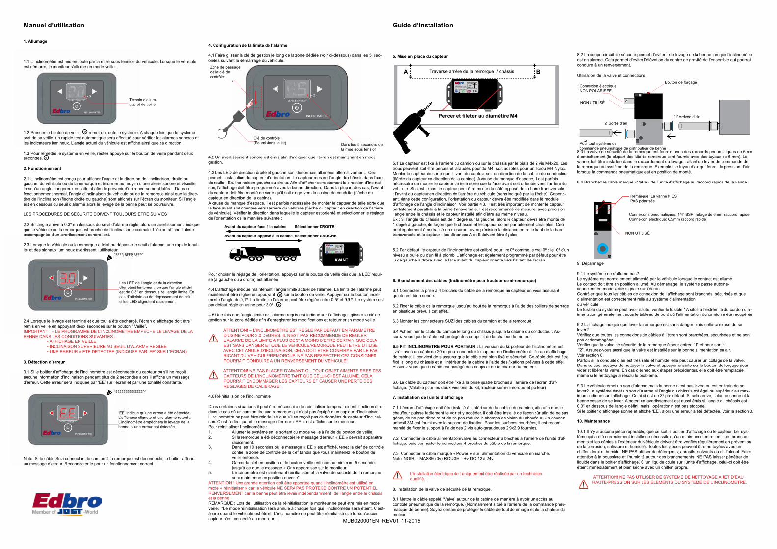
5. Mise en place du capteur
5.1 Le capteur est fixé à l’arrière du camion ou sur le châssis par le biais de 2 vis M4x20. Les trous peuvent soit être percés et taraudés pour du M4, soit adaptés pour un écrou M4 Nyloc. Monter le capteur de sorte que l’avant du capteur soit en direction de la cabine du conducteur (flèche du capteur en direction de la cabine). A cause du manque d’espace, il est parfois nécessaire de monter le capteur de telle sorte que la face avant soit orientée vers l’arrière du véhicule. Si c’est le cas, le capteur peut être monté du côté opposé de la barre transversale : l’avant du capteur en direction de l’arrière du véhicule (sens indiqué par la flèche). Cepend-ant, dans cette configuration, l’orientation du capteur devra être modifiée dans le module d’affichage de l’angle d’inclinaison. Voir partie 4.3. Il est très important de monter le capteur parfaitement parallèle à la barre transversale. Il est recommandé de mesurer avec précision l’angle entre le châssis et le capteur installé afin d’être au même niveau.Ex : Si l’angle du châssis est de 1 degré sur la gauche, alors le capteur devra être monté de 1 degré à gauche, de façon que le châssis et le capteur soient parfaitement parallèles. Ceci peut également être réalisé en mesurant avec précision la distance entre le haut de la barre transversale et le capteur : les distances A et B doivent être égales
5.2 Par défaut, le capteur de l’inclinomètre est calibré pour lire 0º comme le vrai 0º : le 0º d’un niveau a bulle ou d’un fil à plomb. L’affichage est également programmé par défaut pour être lu de gauche à droite avec la face avant du capteur orienté vers l’avant de l’écran.
6. Branchement des câbles (Inclinomètre pour tracteur semi-remorque)
6.1 Connecter la prise à 4 broches du câble de la remorque au capteur en vous assurant qu’elle est bien serrée.
6.2 Fixer le câble de la remorque jusqu’au bout de la remorque à l’aide des colliers de serrage en plastique prévu à cet effet..
6.3 Monter les connecteurs SUZI des câbles du camion et de la remorque
6.4 Acheminer le câble du camion le long du châssis jusqu’à la cabine du conducteur. As-surez-vous que le câble est protégé des coups et de la chaleur du moteur.
6.5 KIT INCLINOMETRE POUR PORTEUR : La version du kit porteur de l’inclinomètre est livrée avec un câble de 20 m pour connecter le capteur de l’inclinomètre à l’écran d’affichage de cabine. Il convient de s’assurer que le câble est bien fixé et sécurisé. Ce câble doit est être fixé le long du châssis et à l’intérieur de la cabine à l’aide des fixations prévues à cette effet. Assurez-vous que le câble est protégé des coups et de la chaleur du moteur.
6.6 Le câble du capteur doit être fixé à la prise quatre broches à l’arrière de l’écran d’af-fichage. (Valable pour les deux versions du kit, tracteur semi-remorque et porteur)
7. Installation de l’unité d’affichage
7.1 L’écran d’affichage doit être installé à l’intérieur de la cabine du camion, afin afin que le chauffeur puisse facilement le voir et y accéder. Il doit être installé de façon sûr afin de ne pas gêner, de ne pas distraire et de ne pas réduire le champs de vision du chauffeur. Un coussin adhésif 3M est fourni avec le support de fixation. Pour les surfaces courbées, il est recom-mandé de fixer le support à l’aide des 2 vis auto-taraudeuss 2.9x2.9 fournies.
7.2 Connecter le câble alimentation/valve au connecteur 6 broches a l’arrière de l’unité d’af-fichage, puis connecter le connecteur 4 broches du câble de la remorque.
7.3 Connecter le câble marqué « Power » sur l’alimentation du véhicule en marche.Note: NOIR = MASSE (0v) ROUGE = +v DC 12 à 24v.
L’installation électrique doit uniquement être réalisée par un technicien qualifié.
8. Installation de la valve de sécurité de la remorque.
8.1 Mettre le câble appelé “Valve” autour de la cabine de manière à avoir un accès au contrôle pneumatique de la remorque. (Normalement situé à l’arrière de la commande pneu-matique de benne). Soyez certain de protéger le câble de tout dommage et de la chaleur du moteur.
MOUNTTHIS
WAY UP
Model: TINCPower Input: DC 12-24vSerial No: ETINC 00-00-00Made in United Kingdom
Traverse arrière de la remorque / châssisA B
Percer et fileter au diamètire M4
8.2 La coupe-circuit de sécurité permet d’éviter le le levage de la benne lorsque l’inclinomètre est en alarme. Cela permet d’éviter l’élévation du centre de gravité de l’ensemble qui pourrait conduire à un renversement.
Utilisation de la valve et connections
8.3 La valve de sécurité de la remorque est fournie avec des raccords pneumatiques de 6 mm à emboîtement (la plupart des kits de remorque sont fournis avec des tuyaux de 6 mm). La vanne doit être installée dans le raccordement du levage : allant du levier de commande de la remorque au système de la remorque. Exemple : le tuyau d’air qui fournit la pression d’air lorsque la commande pneumatique est en position de monté.
8.4 Branchez le câble marqué «Valve» de l’unité d’affichage au raccord rapide de la vanne.
9. Dépannage
9.1 Le système ne s’allume pas?Le système est normalement alimenté par le véhicule lorsque le contact est allumé.Le contact doit être en position allumé. Au démarrage, le système passe automa- tiquement en mode veille signalé sur l’écran.Contrôler que tous les câbles de connexion de l’affichage sont branchés, sécurisés et que d’alimentation est correctement relié au système d’alimentationdu véhicule.Le fusible du système peut avoir sauté, vérifier le fusible 1A situé à l’extrémité du cordon d’al-imentation généralement sous le tableau de bord où l’alimentation du camion a été récupérée.
9.2 L’affichage indique que lever la remorque est sans danger mais celle-ci refuse de se lever?Vérifiez que toutes les connexions de câbles à l’écran sont branchées, sécurisées et ne sont pas endommagées.Vérifier que la valve de sécurité de la remorque à pour entrée “1” et pour sortie “2”. Assurez-vous aussi que la valve est installée sur la bonne alimentation en air. Voir section 8.Parfois si la conduite d’air est très sale et humide, elle peut causer un collage de la valve. Dans ce cas, essayer de nettoyer la valve et appuyer ensuite sur le bouton de forçage pour vider et libérer la valve. En cas d’échec aux étapes précédentes, elle doit être remplacée même si le nettoyage a résolu le problème.
9.3 Le véhicule émet un son d’alarme mais la benne n’est pas levée ou est en train de se lever? Le système émet un son d’alarme si l’angle du châssis est égal ou supérieur au max-imum indiqué sur l’affichage. Celui-ci est de 3º par défaut. Si cela arrive, l’alarme sonne et la benne cesse de se lever. A noter: un avertissement est aussi émis si l’angle du châssis est 0.3° en dessous de l’angle défini mais l’opération n’est pas stoppée.Si le boitier d’affichage sonne et affiche ‘EE’, alors une erreur a été détectée. Voir la section 3.
10. Maintenance 10.1 Il n’y a aucune pièce réparable, que ce soit le boitier d’affichage ou le capteur. Le sys-tème qui a été correctement installé ne nécessite qu’un minimum d’entretien : Les branche-ments et les câbles à l’extérieur du véhicule doivent être vérifiés régulièrement en prévention de la corrosion, salissure et humidité. Toutes les pièces peuvent être nettoyées avec un chiffon doux et humide. NE PAS utiliser de détergents, abrasifs, solvants ou de l’alcool. Faire attention à la poussière et l’humidité autour des branchements. NE PAS laisser pénétrer de liquide dans le boitier d’affichage. Si un liquide coule sur l’unité d’affichage, celui-ci doit être éteint immédiatement et bien séché avec un chiffon propre. ATTENTION! NE PAS UTILISER DE SYSTEME DE NETTOYAGE A JET D’EAU HAUTE-PRESSION SUR LES ELEMENTS DU SYSTEME DE L’INCLINOMETRE.
Connexion électrique NON POLARISEE
NON UTILISÉ
Bouton de forçage
‘2’ Sortie d’air‘1’ Arrivée d’air
Pour tout système de commande pneumatique de distributeur de benne
Remarque: La vanne N’EST PAS polarisée
NON UTILISÉ
Connexions pneumatiques: 1/4” BSP filetage de 6mm, raccord rapideConnexion électrique: 6.5mm raccord rapide
MUB020001EN_REV01_11-2015
Zone de passage de la clé de contrôle.
Dans les 5 secondes de la mise sous tension
Clé de contrôle(Fourni dans le kit)

VEHICLE ANGLE º
INCLINOMETER
4. Einstellen des Alarmgrenzwertes
4.1 Innerhalb von fünf Sekunden ab dem Einschalten der Zündung muss der Magnetschlüssel über den Schlüsselsensor geführt werden.
4.2 Ein kurzes akustisches Signal zeigt an, dass sich das Displaymodul nun im Programmier-modus befindet.
4.3 Die linke und rechte Richtungs-LED leuchtet abwechselnd. Dies ermöglicht die Einstellung der Sensorrichtung. Der Sensor misst den Seitenneigungswinkel des Fahrgestells. Damit die Neigungsrichtung korrekt angezeigt wird, muss die Einbaurichtung des Sensormoduls in das Displaymodul einprogrammiert werden. Üblicherweise sollte die Vorderseite des Sensors in Richtung der Fahrerkabine angebracht werden. Manchmal ist es aber aus Platzgründen erforderlich, den Sensor mit seiner Vorderseite in Richtung des Fahrzeughecks zu montieren. Die Richtung des Sensors ist zu überprüfen und wie folgt zu programmieren:
Um die Richtung auszuwählen, muss die Standby-Taste einmal gedrückt werden, wenn die entsprechende LED aufleuchtet.
4.4 Das Display zeigt nun den einprogrammierten Alarmgrenzwert an. Dieser Grenzwert kann durch Drücken der Standby-Taste verstellt werde n. Durch jeden Tastendruck wird der Winkel um 0,1° erhöht. Der Alarmgrenzwert kann zwischen 0,5° und 9,9° eingestellt werden; die Werkseinstellung beträgt 3,0°.
4.5 Sobald der gewünschte Alarmgrenzwert auf dem Display angezeigt wird, muss der Magnetschlüssel erneut über den Schlüsselsensor geführt werden, um die Einstellung zu speichern und das System wieder in den Standby-Modus zu versetzen.
VORSICHT! – DIE WERKSEINSTELLUNG DES NEIGUNGSMESSERS BE TRÄGT 3°. ES IST NICHT RATSAM, DEN ALARMGRENZWERT AUF ÜBER 3° EIN ZUSTELLEN, WENN NICHT KLAR IST, OB DIE SICHERHEIT GEWÄHRLEISTET IST UND DAS FAHRZEUG BZW. DER ANHÄNGER MIT DIESEM WINKEL BETRIE BEN WERDEN KANN. DIES SOLLTE VOM HERSTELLER DES FAHRZEUGS BZW. DES ANHÄNGERS BESTÄTIGT WERDEN. ANDERNFALLS BESTEHT DIE GE FAHR, DASS DAS FAHRZEUG UMKIPPT. VORSICHT! – LEGEN SIE KEINE MAGNETEN ODER MAGNETISCHE GE GENSTÄNDE IN DER NÄHE DES NEIGUNGSMESSERSENSORS AB, WENN DIESER EINGESCHALTET IST, WEIL DADURCH DER SENSOR BESCHÄDIGT WERDEN ODER DIE KALIBRIERUNG VERLOREN GEHEN KANN
4.6 Messfunktion des Neigungsmessgeräts deaktivieren
In bestimmten Situationen kann es erforderlich sein, die Messfunktion des Neigungsmess-geräts zu deaktivieren. Dies gilt zum Beispiel wenn die Zugmaschine mit einem Auflieger verbunden wird, der nicht mit einem Neigungssensor ausgestattet ist.
Die Messfunktion kann nur deaktiviert werden, wenn das Gerät keine Daten von dem Neigungssensor empfängt. Dabei erscheint die Fehlermeldung „EE“ auf dem Display in der Fahrerkabine.
Deaktivierung der Messfunktion:1. Das Gerät durch Drücken des Standby Knopfes anschalten und aus dem Stand by Modus erwecken.2. Wenn der Trailer vom Truck getrennt ist, erscheint nach kurzem Warten die Fehlermeldung „EE“ auf dem Display.3. Während „EE“ auf dem Display steht, innerhalb von 10 Sekunden den Magnet schlüssel an den Schlüsselsensor halten, gleichzeitig den Standby-Knopf drücen.4. Magnetschlüssel und Standby-Knopf mindestens 5 Sekunden in Position halten bis „Or“ angezeigt wird.5. Messfunktion ist nun deaktiviert und das Kippabschaltventil bleibt in geöffneter Position.
Achtung: Bei Nutzung des Neigungsmessers mit deaktivierter Messfunktion, ist das Fahrzeug nicht vor einem möglichen Umkippen geschützt. Die Kippmulde kann unabhängig von dem Fahrgestellwinkel angehoben werden!Hinweis: Der Display kann im deaktivieren Messmodus nicht in den Standby-Modus versetzt werden.*Der deaktivierte Messemodus wird beendet, wenn der Neigungsmesser ausgeschaltet wird, z.B. wenn die Zündung ausgeschaltet wird.Der Neigungsmesser kann nur ausgeschaltet werden, wenn keine Verbindung zwischen Neigungssensor und Display besteht.
MOUNTTHIS
WAY UP
Model: TINCPower Input: DC 12-24vSerial No: ETINC 00-00-00Made in United Kingdom
MOUNTTHIS
WAY UP
Model: TINCPower Input: DC 12-24vSerial No: ETINC 00-00-00Made in United Kingdom
FRONT
VEHICLE ANGLE º
INCLINOMETER
“BEEEEEEEEEEEEEP”
VEHICLE ANGLE º
INCLINOMETER
“BEEP, BEEP, BEEP”
VEHICLE ANGLE º
INCLINOMETER
Neigungsmesser für sicheres Kippen
1. Ein-/Ausschalten
1.1 Der Neigungsmesser wird durch Einschalten der Zündung aktiviert. Bei eingeschalteter Zündung befindet sich das Display im Standby-Modus.
1.2 Durch Drücken der Standby-Taste wird das System aus dem Standby aufgeweckt. Jedes Mal, wenn der Standby-Modus beendet wird, führt das Display einen schnellen Selb-sttest durch, wobei das Warnsignal ertönt und alle LEDs aufleuchten. Danach werden der aktuelle Winkel des Fahrzeugs in Grad sowie die Richtung der Fahrzeugneigung angezeigt.
1.3 Um das System wieder in den Standby-Modus zu versetzen, muss die Standby-Taste für zwei Sekunden gedrückt werden.
2. Betrieb
2.1 Der Neigungsmesser zeigt die Seitenneigung des Fahrzeugs oder Anhängers an und löst einen akustischen/optischen Alarm aus, wenn ein gefährlicher Winkel erreicht wird, um ein Umkippen zu verhindern. Bei normalem Betrieb wird der aktuelle Winkel des Fahrzeugs bzw. des Anhängers und die Neigungsrichtung (links/rechts) auf dem Displaymodul in der Fahrerk-abine angezeigt. Solange der Winkel kleiner als der voreingestellte Alarmgrenzwert ist, kann der Kippvorgang durchgeführt werden.ÜBLICHE SICHERHEITSBESTIMMUNGEN SIND DENNOCH EINZUHALTEN.
2.2 Sobald der Kippwinkel nur noch 0,3° vom voreingestellten Alarmgrenzwert entfernt ist, ertönt ein Warnton, der signalisiert, dass bald ein unsicherer Winkel erreicht wird. Die Anzeige auf dem Display blinkt und ein Signalton erklingt.
2.3 Wenn das Fahrzeug oder der Anhänger den voreingestellten Alarmgrenzwert erreicht oder überschreitet, ertönt ein Signalton und das Display blinkt schnell. Dabei verhindert das System, dass die Kippmulde weiter angehoben wird, indem es das Kippventil abschaltet.DIE KIPPMULDE SOLLTE UNVERZÜGLICH ABGESENKT WERDEN UND DAS FAHRZEUG SOLLTE AN EINER ANDEREN STELLE NEU POSITIONIERT WERDEN, DAMIT DER GRENZWERT NICHT ÜBERSCHRITTEN WIRD.
2.4 Wenn der Kippvorgang beendet und die Kippmulde wieder komplett abgesenkt ist, sollte das Display wieder in den Standby-Modus versetzt werden, indem die Standby-Taste für zwei Sekunden gedrückt wird.
WICHTIG! – DAS SYSTEM VERHINDERT, DASS DIE KIPPMULDE UNTER FOLGENDEN BEDINGUNGEN ANGEHOBEN WERDEN KANN: • DISPLAY IST IM STANDBY- MODUS • SEITENNEIGUNG IST GRÖSSER ALS VOREINGESTELLTER ALARMGREN ZWERT • EIN FEHLER WURDE ERKANNT (DISPLAY ZEIGT „EE“ AN)
3. Fehlererkennung
3.1 Wenn das Displaymodul des Neigungsmessers vom Sensormodul getrennt wird oder länger als zwei Sekunden keine Sensordatenempfängt, wird eine Fehlermeldung angezeigt. Dies wird durch „EE“ auf dem Display und einem konstanten Warnton verdeutlicht.
Hinweis: Wenn das Spiralkabel zwischen Zugmaschine und Anhänger getrennt wird, zeigt das Display eine Fehlermeldung an. Das Spiralkabel muss dann wieder angeschlossen werden
Power EINAuf der Standby-Anzeige
Winkel - Und richtungs-LED blinken wenn der winkel nur noch 0.3° vom boreingestell-ten grenzwert entfernt ist. Sie blinken schnell, wenn der grenzwert erreicht oder überschritten wird.
‘EE’ zeigt an, dass ein Fehler erkannt wurde. Die Anzeige blinkt und ein kosstanter Warnton erklingt. DER NEIGUNGSMESSER VERHINDERT DAS ANHEBEN DER KIP-PMULDE, WENN EIN FEHLER ERKANNT WURDE.
VerwaltungsmodusSchlüsselbereich
Elektronischer Schlüssel(im Set enthalten)
Innerhalb va 5 sekunden ab einschalten der züdung
Sensorvorderselte In Richtung Fahrekablne RECHTS auswählen
Sensorvorderselte In Richtung Fahrzeugheck LINKS auswählen
Installationsanleitung ung
5. Einbau des Sensors
5.1 Der Sensor wird mit zwei Schrauben M4x20 am hintersten Querträger des Anhängers oder des Fahrgestells befestigt. Um den Sensor befestigen, können die mitgelieferten Schrau-ben und Stoppmuttern verwendet werden. Alternativ können Löcher gebohrt und mit Gewinde M4 versehen werden. Der Sensor ist so anzubringen, dass seine Vorderseite in Richtung der Fahrerkabine weist. Gelegentlich ist dies aus Platzgründen nicht möglich. In solchen Fällen darf der Sensor auch in Richtung Fahrzeugheck angebracht werden. Dann muss jedoch die Sensorrichtung an dem Displaymodul neu eingestellt werden. Siehe Abschnitt 4.3. Der Sensor muss absolut parallel zum Querträger eingebaut werden. Es wird empfohlen, eine präzise Winkelmessung am Fahrgestell vorzunehmen und den Sensor im selben Winkel anzubringen. D. h. wenn das Fahrgestell um 1° nach links geneigt ist, muss der Sensor ebenfalls um 1° nach links geneigt montiert werden, damit Fahrgestell und Sensor parallel sind. Es ist auch möglich, den Abstand von der Oberkante des Querträgers genau zu messen und darauf zu achten, dass die Werte „A“ und „B“ gleich groß sind.
5.2 Die Werkseinstellung des Neigungsmessersensors wurde auf 0° kalibriert. Dies entspricht der Anzeige einer Wasserwaage oder eines Senklots. An dem Displaymodul ist ebenfalls werksseitig eingestellt, dass die Vorderseite des Sensors in Richtung Fahrerkabine zeigt.
6. Kabelführung (für Trailer Neigungsmesser Kit)
6.1 Den 4-poligen Stecker am Anhängerkabel mit dem Sensor verbinden und dabei auf festen und sicheren Sitz achten.
6.2 Das Anhängerkabel entlang des Anhängers mit den Kabelbindern befestigen.
6.3 Die Spiralkabelstecker an der Zugmaschine und am Anhängerkabel anbringen.
6.4 Das Zugmaschinenkabel am Fahrgestell der Zugmaschine entlang und in die Fahrerka-bine führen. Darauf achten, dass das Kabel vor Motorwärme oder Beschädigung geschützt ist.
6.5 (Inclinometer für Chassis)Chassis Inclinometer: Im Lieferumfang der Chassis Version des Inclinometers ist ein 20 Meter langes Kabel enthalten, das den Inclinometer Sensor mit dem Displaymodul in der Kabine verbindet. Diese Kabel sollte mit dem Sensor verbunden sein. Es muss sichergestellt werden, dass es fest und sicher sitzt. Danach muss das Kabel der Länge vom Chassis zur Fahrerka-bine entsprechend mit den zur Verfügung gestellten Kabelbindern fixiert werden. Achten Sie darauf, dass das Kabel vor Motorwärme und Beschädigung geschützt ist.
6.6 Das Sensorkabel muss an der Rückseite des Kabinendisplays in den 4-Loch Stecker gesteckt werden. (Gilt für Trailer und Chassis Inclinometer)
7. Einbau des Displaymoduls
7.1 Das Displaymodul sollte im Innern der Fahrerkabine so eingebaut werden, dass sie aus der Fahrerposition problemlos erkannt und erreicht werden kann. Sie sollte an einer sicheren Stelle montiert werden, wo sie das Fahren nicht behindert und den Fahrer weder ablenkt noch sein Blickfeld einschränkt. An der Unterseite der Halterung ist ein 3M Klebepad angebracht, jedoch wird empfohlen, die Halterung auf strukturierten und gekrümmten Flächen mit den zwei mitgelieferten selbstschneidenden Schrauben 2,9x9,5 zu befestigen.
7.2 Das Netz-/Ventilkabel mit dem 6-poligen Stecker auf der Rückseite des Displaymoduls verbinden und dann den 4-poligen Stecker des Anhängerkabels anschließen.
7.3 Das Kabel mit der Aufschrift „Power“ an die Stromzufuhr der Zündung anschließen.Hinweis: SCHWARZ = MASSE (0 V), ROT = 12–24 V DC
Die Elektroinstallation sollte nur von einem qualifizierten Techniker durchgeführt werden. Das System muss abgesichert werden – eine 1-Ampere-Sicherung plus Sicherungshalter sind beigefügt.
8. Einbau des Kippabschaltventils
8.1 Das Kabel mit der Aufschrift „Valve“ (Ventil) bis zum Luftschaltventil verlegen. Darauf achten, dass das Kabel vor Wärme und Beschädigung geschützt ist.
8.2 Das Kippabschaltventil soll verhindern, dass die Kippmulde weiter angehoben werden kann, wenn sich das System im Alarmzustand befindet. Dadurch wird vermieden, dass sich der Schwerpunkt der Kippmulde weiter nach oben verschiebt und der Anhänger umkippt.
Betätigung und Anschlüsse des Ventils
Hinterer Querträger des Anhängers / Fahrgestells
0°
A B
Vorbohren und Gewinde schneiden für Schrauben M4
8.3 Das Kippabschaltventil ist mit 6 mm Steckkupplungen ausgestattet (Die meisten Hydrau-likanlagen beinhalten 6mm Luftanschlüsse). Das Ventil sollte an der Zuluftleitung installiert werden, die vom Luftschaltventil zum Kippventil führt, d. h. an dem Schlauch, der Luft zuführt, wenn sich der Luftschaltventil in der Position Anheben befindet.
8.4 Das von dem Displaymodul kommende Kabel mit der Aufschrift „Valve“ (Ventil) mit den Steckkupplungen des Ventils verbinden. Hinweis: Der Ventilstecker ist NICHT gepolt.
9. Fehlersuche
9.1 Das System wird nicht mit Strom versorgt.Im Normalfall wird das System durch Einschalten der Zündung mit Strom versorgt.Die Zündung muss EINGESCHALTET sein. Beim Einschalten geht das System automatisch in den Standby-Modus über, der auf dem Display angezeigt wird.Es ist zu prüfen, ob alle Kabelverbindungen zum Displaymodul fest und sicher angeschlossen sind und ob das Netzkabel korrekt mit der Stromversorgung des Fahrzeugs verbunden ist.Die Sicherung könnte durchgebrannt sein. Die 1-Ampere-Sicherung, die sich am Ende des Stromkabels meist unter dem Armaturenbrett am/im Sicherungskasten befindet, ist zu prüfen.
9.2 Das Display zeigt an, dass ein sicherer Kippvorgang möglich ist, aber die Kippmulde lässt sich nicht anheben.• Es ist zu prüfen, ob alle Kabelverbindungen zum Displaymodul fest und sicher angeschlos-sen sowie unbeschädigt sind.• Es ist zu prüfen, ob das Kippabschaltventil korrekt eingebaut ist. Das Ventil ist mit „1“ für Eingang und „2“ für Ausgang markiert. Außerdem ist zu prüfen, ob das Ventil in die korrekte Luftleitung eingebaut wurde. Siehe Abschnitt 8.• Manchmal führen Schmutz und Feuchtigkeit in der Luftleitung dazu, dass das Ventil klemmt. Das Ventil reinigen und durch Drücken der Übersteuerungstaste den Ventilschieber lösen. Wenn das Ventil versagt, muss es durch ein neues ersetzt werden, auch wenn durch das Reinigen zunächst das Problem behoben werden kann.
9.3 Das System gibt Alarm, obwohl sich Fahrzeug/Anhänger auf ebenem Untergrund befindet.Das System geht in den Alarmzustand über, wenn der Fahrgestellwinkel gleich oder größer als der maximale, im Displaymodul eingestellte Kippwinkel ist. Das System ist werksseitig auf 3° eingestellt, d. h. wenn die seitliche Neigung des Fahrgestells gleich oder größer als 3° beträgt, wird der Alarm ausgelöst und der Kippvorgang gestoppt. Hinweis: Ein Warnton ertönt bereits, wenn der Winkel 0,3° kleiner als der Alarmgrenzwert ist, aber die Kippfunktion wird davon nicht beeinträchtigt.Wenn das System Alarm gibt und „EE“ im Display anzeigt, wurde ein Fehler erkannt. Siehe Abschnitt 3.
10. Wartung
10.1 Im Display- und Sensormodul befinden sich KEINE TEILE, DIE VOM BENUTZER ZU WARTEN SIND. Bei korrekter Installation hat das System nur einen minimalen Wartungsauf-wand. Die Stecker und Kabel außen am Fahrzeug sollten regelmäßig auf Korrosion, Ver-schmutzung und Feuchtigkeitseintritt überprüft werden. Alle Teile können mit einem weichen, feuchten Tuch gereinigt werden. KEINE Reinigungsmittel, Scheuermittel, Lösungsmittel oder Alkohol verwenden. An allen Anschlüssen sind Feuchtigkeit und Schmutzansammlungen zu vermeiden. Es darft KEINE Feuchtigkeit in das Displaymodul eindringen. Falls eine Flüssigkeit auf das Displaymodul geschüttet wird, sollte das Gerät sofort ausgeschaltet und mit einem sauberen Tuch sorgfältig getrocknet werden. WARNUNG! KEIN TEIL DES NEIGUNGSMESSERSYSTEMS DARF MIT HOCH DRUCK- ODER WASSERSTRAHLREINIGERN BEHANDELT WERDEN
StromanschlussNICHT POLARISIERT
FREI
“2” Luft AUSLASS
“1” Luft EINLASS
Übersteuerungstaste
ZDE 199 003 001 * 11/2015
Heck desKippers Hebel
Stromanschluss Ventil - NICHT POLARISIERT
FREI
Pneumatische Anschlüsse: 1/4” BSP-Gewinde 6mm SteckverbindungElektrische Anschlüsse: 6.5mm Steckkupplungen
MUB020001EN_REV01_11-2015

105mm
65m
m
VEHICLE ANGLE º
INCLINOMETER
Fixing Template - Photocopy before use - DO NOT SCALEDisplay Mounting Bracket
54mm
45mm
Dia 3mm
44mm
Inclinometer Sensor
110.10mm
57.4mm
36mm
M4
98.40mm
THIS W
AY UP
Suzi Connector
THIS W
AY UP
M4
Dia 22m
m
Surface mount Suzi Bracket (Suggested Design -NOT SUPPLIED IN KIT)
BEND 90º
Suggested Material: 4mm Aluminium
Service Contact:Jost UK Ltd.Edbro House,Nelson Street,Bolton,Lancashire,BL3 2JJ [email protected]: +44 (0) 1204 52 8888fax: +44 (0) 1204 53 1957
Electrical:Operating Voltage................................................................................................DC 12-24vOperating Current .............................................................................................. 350mAFuse Rating...................................................................................................................1A
Sensor: Accuracy...............................................................................................................+/- 0.1ºRange...................................................................................................................0.0º to 9.9ºRepeatability.........................................................................................................+/-0.1º
Environmental:Waterproof rating......................................................................Sensor: IP69K Display: IP52Relative Humidty ......................................................................Sensor: 100% Display: 100%Operating Temerature........................................................................................-10 to +55ºC
Size........................................Display:W106xH67xD22mm Sensor: W110xH55xD25mmWeight......................................................................................Display: 90g Sensor : 135gCable Length..................................................................................................Power Lead: 2m Valve Lead: 5m Tractor Cable: 7m Suzi: 4m Max Extension Trailer Cable: 13m
Kit Contents:
MOUNTTHIS
WAY UP
Model: TINCPower Input: DC 12-24vSerial No: ETINC 00-00-00Made in Great Britain
Display Unit x1 Sensor Unit x1 Cut off Valve x1 Mounting Bracket x1
Power/Valve Cable x1Tractor Cable 1xTrailer kit only Suzi Cable x1
Trailer Kit Only
1A
Trailer Cable 1xTrailer Kit Only
1A Fuse & Fuse Holder x1
Managers Key x1
Instruction Sheet x 2
2.9 x 9.5 ST Screw x2 M4 Washer x2
M4x20 SS Bolt x2 M4 Nylon Nut x2
200mm Cable Tie x25
Suzi Connections:
21
54
76
3
12
34
67
5
1. Data ‘A’ RS4852. NOT USED3. NOT USED4. POWER +V DC5. POWER GND6. NOT USED7. DATA ‘B’ RS485
1. DATA ‘A’ RS4852. NOT USED3. NOT USED4. POWER +V DC5. POWER GND6. GND7. DATA ‘B’ RS485
FRONT OF CONNECTOR (TRACTOR/TRAILER)
FRONT OF CONNECTOR (SUZI CABLE)
V1.0 AUG 2015
READ AND UNDERSTANDFULLY BEFORE INSTALLING
AND OPERATING
Inclinometer
VEHICLE ANGLE º
INCLINOMETER
Indicates vehicle is leaning LEFTVehcile angle in degrees (eg. 1.3°)
Indicates vehicle is leaning RIGHTManagement
Mode Key Aera
Power/Standby Button Power/Standby Indicator
Sensor Socket Power / Valve / AUX Socket
Mounting Bracket Fixing
WIRING CONNECTIONS
+v +v
GND GND
+v
GND
+v
GND
A
B
SENSOR SOCKET POWER/OUTPUT SOCKET
POWER DATA Power Input
Valve Output
AUX* Output
MOUNTTHIS
WAY UP
Model: TINCPower Input: DC 12-24vSerial No: ETINC 00-00-00Made in Great Britain
110mm
SENSOR
Sensor Connector
DATA ’A’
DATA ‘B’ GND
+12v DC
* Optional
Sensor Cable x 1Rigid Kit Only
MUB020001EN_REV01_11-2015