ramanna enterprises office address- 3e/7 b.p , n.i.t...
TRANSCRIPT

RAMANNA ENTERPRISES
OFFICE ADDRESS- 3E/7 B.P , N.I.T FARIDABAD, HARYANA.
INSTRUCTION / SERVICE MANUAL FOR
PRECISION MANUAL SURFACE GRINDER
MODELS - 7X14
9X14
9X18
10X20
12X24
15X30
2
CONTENTS
1. Machine Parts Nomenclature 3 - 4
Normal type 3
Excello type 4
2. Installation Guidelines 5 - 9
General & Machine safety rules 5
Transit 6
Unpacking 7
Choice of site 7
Installation 8
Lubrication System Line Diagram 10
3. Grinding 12
4. Selection of suitable Grinding wheel 12
5. Preventive Maintenance 15
6. Trouble Shooting 15
7. Coolant Accessories and Fitting 16
8. Warranty Terms & Conditions 18

3
1. Machine Parts Nomenclature Normal Machine

4
Excello Type
5
2. Installation Guidelines
General & Machine Safety Rules
Do
The employer must select trained, qualified personnel to machine.
For persons with long hair, their hair must be properly restrained or wear a hat before operating or maintaining the machine.
When operating the machine, safety glasses, a filter masks and work safety shoes must be worn.
The machine and its surrounding area must be kept clean and orderly so to prevent slippery surfaces and to remove unnecessary obstacles.
All protective guards must be closed at all times, except when maintenance work is being done.
Before maintenance work, the power source should be turned off and only proper tool should be used.
Only use grinding wheel with a maximum peripheral speed of 2800rpm or greater.
When inspecting electrical sections of the machine, insulating gloves, rubber or leather boots and other non-conducting protective items should be used.
Before starting up the wheel spindle motor, first inspect the grinding wheel and check the turning direction of the wheel spindle. After starting the wheel spindle motor, let the grinding wheel spin freely for at least two minutes before starting to grind the work piece.
Make sure the surface of the magnetic chuck is clean before mounting work pieces.
Use the proper clamps when mounting non-magnetic material work pieces such as aluminium, graphite, etc, or work pieces that are difficult to be hold on the magnetic chuck. These clamps cannot come into contact with the grinding wheel.
When the grinding wheel is not turning, the operator should check with his hands and see whether the work piece is firmly attached to the magnetic chuck.
For wet grinding, before turning ON the spindle motor, first turn ON the coolant system.

6
Don’t
Persons wearing ties, gloves, loose fitting clothing and shirts with very long sleeves must not operate or maintain the machine.
Operation personnel must not lean on the machine.
Combustible liquids must not be used as a cutting fluid.
The machine should not be used to grind lumber, plastics or other combustible materials.
When grinding, besides securely mounting the work piece, one should make sure no other object is placed on the machine.
After the wheel spindle motor is turned off, do not use your hand or any other object to stop or slow down the grinding wheel.
During grinding and before the grinding wheel stops rotating after work is finished; do not attempt to clean the shavings of the work piece or to move the work piece.
When taking off the grinding wheel, use a flange remover to detach it. Do not use any method that involves pounding the grinding wheel. This could result in damage to the grinding wheel.
Transit
THIS MACHINE HAS BEEN FULLY TESTED, ADJUSTED AND INSPECTED FOR CORRECT ALIGNMENT AND OPERATION PRIOR TO DISPATCH, IN TRANSIT OR INSTALLATION, PLEASE ENSURE THAT THE MACHINE IS NOT BUMPED WHEN BEING ROLLED OR SET DOWN TO AVOID ANY FAILURE.
By Fork lifter or By Hoist
7
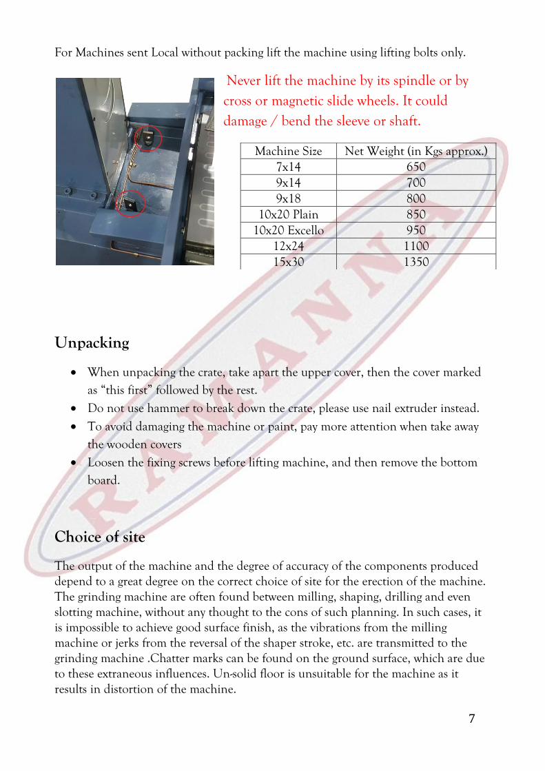
For Machines sent Local without packing lift the machine using lifting bolts only.
Never lift the machine by its spindle or by cross or magnetic slide wheels. It could damage / bend the sleeve or shaft.
Unpacking
When unpacking the crate, take apart the upper cover, then the cover marked as “this first” followed by the rest.
Do not use hammer to break down the crate, please use nail extruder instead.
To avoid damaging the machine or paint, pay more attention when take away the wooden covers
Loosen the fixing screws before lifting machine, and then remove the bottom board.
Choice of site
The output of the machine and the degree of accuracy of the components produced depend to a great degree on the correct choice of site for the erection of the machine. The grinding machine are often found between milling, shaping, drilling and even slotting machine, without any thought to the cons of such planning. In such cases, it is impossible to achieve good surface finish, as the vibrations from the milling machine or jerks from the reversal of the shaper stroke, etc. are transmitted to the grinding machine .Chatter marks can be found on the ground surface, which are due to these extraneous influences. Un-solid floor is unsuitable for the machine as it results in distortion of the machine.
Machine Size Net Weight (in Kgs approx.) 7x14 650 9x14 700 9x18 800
10x20 Plain 850 10x20 Excello 950
12x24 1100 15x30 1350
8
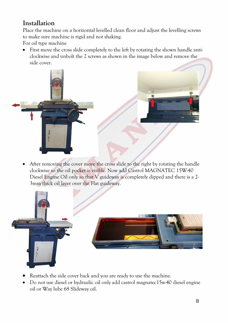
Installation Place the machine on a horizontal levelled clean floor and adjust the levelling screws to make sure machine is rigid and not shaking. For oil type machine First move the cross slide completely to the left by rotating the shown handle anti-
clockwise and unbolt the 2 screws as shown in the image below and remove the side cover.
After removing the cover move the cross slide to the right by rotating the handle clockwise so the oil pocket is visible. Now add Castrol MAGNATEC 15W-40 Diesel Engine Oil only so that V guideway is completely dipped and there is a 2-3mm thick oil layer over the Flat guideway.
Reattach the side cover back and you are ready to use the machine. Do not use diesel or hydraulic oil only add castrol magnatec15w-40 diesel engine
oil or Way lube 68 Slideway oil.

9
For Ball type machine After unloading and erection of the machine at workplace, lift the magnetic slide
to remove the cylindrical rods (placed to avoid surface contact) and replace them with ball strips sent along with the machine.
Do this for both the guide ways and place the magnetic slide down.
Electric Connection
All our machines use 3 phase motors. Make the connections to the starter and you are ready to use the machine. Make sure the grinding wheel is rotation clockwise, if not reverse the connections.
If coolant is along with the machine provide separate 3 phase connections to it.
10
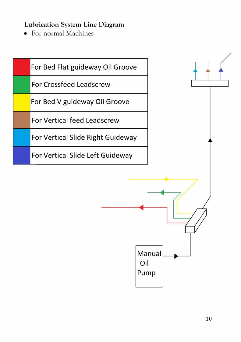
Lubrication System Line Diagram For normal Machines

11
For Excello type
12
3. Grinding The grinding results obtained depend to a very degree on the choice of the
correct grinding wheel and suitable operation.
Stock removal efficiency. For intensive stock removal a coarse grain (about 30-36) should be used. The wheel is dressed by passing the diamond over quickly so that the surface of the wheel is roughed and bites well.
Surface finish required If fine finish is to be produced, a finer grain wheel is required (40-80).The diamond in this case is passed slowly over the wheel so as to break up the grain.
Distortion of the workpiece If the workpiece shows too much distortion when being ground, this means that the stock removal was too great and the longitudinal and cross movements of the table was too slow, or the grinding wheel in "clogged".
Undesirable burns and grinding cracks If burn marks and grinding cracks appear, this means that the wheel is too hard, or the wheel "clogged".
4. Selection of suitable Grinding wheel A grinding wheel is a self-sharpening tool composed of discrete abrasive grains held together by a bonding agent with composite structure of many clearance allowance for the cutting edges. The characteristic of a grinding wheel depends upon the combined elements of abrasive, grit size, grade, structure and bond.
Kinds of abrasive A: For common steel grinding. WA: For higher hardness material grinding, such as heat-treated steel, alloy steel, etc. H: Suitable for higher hardness material, particularly high speed steel. C: For cast iron and non-ferrous grinding. GC: For super hard grinding such as tungsten carbide steel.
Grain size Coarse: 10, 12, 14, 16, 20, 24 Medium: 30, 36, 46, 54, 60 Fine: 70, 80, 90, 100,120, 150,180

13
Grade: It indicates the strength of the bond witch hold abrasive. Soft: A to H Medium: I to P Hard: Q to Z
Bond B: Resinoid BF: Resinoid reinforced E: Shellac O: Oxychloride R: Rubber RF: Rubber reinforced S: Silicate V: Vitrified
FACTORS AFFECTING WHEEL SELECTION
The material to be ground and its hardness
ABRASIVE: Aluminium oxide for steel and steel alloys. Silicon carbide for cast iron, non-ferrous and non-metallics. ·GRIT SIZE: Fine grit for brittle materials. Coarse grit for ductile materials. ·GRADE: Hard grade for soft materials. Soft grade for hard materials.
The amount of stock to be removed and the finish required · GRIT SIZE: Coarse grit for rapid stock removal as in rough grinding. Fine grit for high finishing. ·BOND : Vitrified for precision cutting. Resinoid or Rubber for high speed cutting.
Wet or dry GRADE: Wet grinding, as a rule, permits use of wheels at least one grade harder than that of dry grinding without danger of burning the work.
The wheel speed · BOND: Standard vitrified wheels are not exceeding 2,000rpm, for higher speeds are up to 3,600rpm. Standard organic bonded wheels (Resinoid, Rubber or Epoxy) are used for most applications over 2,000rpm up to 6,000rpm. · NOTE: Do not exceed the safe operating speed shown on a wheel tag.
The contact area of grinding · GRIT SIZE: Coarse grit for large contact area. Fine grit for small contact area. GRADE: The smaller contact area, the harder wheel.

14
Example
51 A 36 L 5 V Prefix Abrasive type Abrasive Grain Size Grade Structure Bond type
Manufacturer’s symbol (indicating exact type of abrasive) (use optional)
A - Aluminium Oxide
WA - White Aluminium Oxide
C - Silicon Carbide
GC - Green Silicon Carbide
Coarse Medium Fine
8 30 70
10 36 80
12 46 90
14 54 100
16 60 120
20 150
24 180
Very Fine > 220
Soft Medium Hard
A B C D E F G H I J K L M N O P Q R S T U V W X Y Z
Grade Scale
B: Resinoid
BF: Resinoid reinforced
E: Shellac
O: Oxychloride
R: Rubber
RF: Rubber reinforced
S: Silicate
V: Vitrified
Dense 1
2
3
4
5
6
7
8
9
10
11
12
13
Open Etc.

15
5. Preventive Maintenance
Important:-While using a new machine make sure you use the entire working area of the machine for the first 2 months. If your component is small in size hold it in different place each time to cover the entire working area one by one. Not doing so could lead to slide getting tight on the edges and smooth operating in the centre.
Preventive Maintenance Schedule
Particulars Daily Monthly Annually
Cleaning & Oiling
Check oil level in magnet slide
Oil level in lubrication pump
Cleaning of vertical slides by removing front & rear covers
Check the motor & spindle for any undue noise.
Greasing of Spindle (if required call service engineer)
Grind the magnet surface very light cuts (max 0.05 mm)
6. Trouble Shooting In case any taper is observed in work piece, check the magnet surface using dial
indicator (within 0.01mm/ full length of magnet). If any surface damage or taper is observed, grind the table slowly with light cuts (max 0.05 mm).
In case vibration is observed, dress the wheel. Also check the spring tension of spindle after removing the wheel cover.
In case of any uneven movement in vertical slide, remove the covers of vertical slides & clean with diesel or equivalent oil & lubricate properly.
For any other problem feel free to call us directly.
16
Coolant Accessories and Fitting
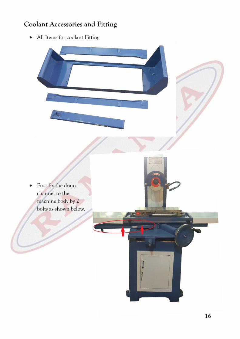
All Items for coolant Fitting
First fix the drain channel to the machine body by 2 bolts as shown below.
17
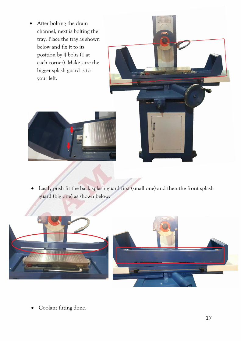
After bolting the drain channel, next is bolting the tray. Place the tray as shown below and fix it to its position by 4 bolts (1 at each corner). Make sure the bigger splash guard is to your left.
Lastly push fit the back splash guard first (small one) and then the front splash
guard (big one) as shown below.
Coolant fitting done.
18
7. Warranty Terms & Conditions
We provide warranty cover for this Machine subject to the following conditions:
1. In accordance with the under-mentioned conditions ( 2 to 8 ), we will rectify defects affecting the machine which are clearly attributable to material and/or manufacturing faults, provided they are reported immediately after being identified, and within 12 months of the date of purchase (the “Warranty Period”).
2. Service may not be available to all the parts of India. Please check with your retailer or contact us directly.
3. The warranty will not be applicable to fragile items such as cosmetic parts or consumable items such as screw, spindle bearings. Warranty liability will not be triggered by minor variances from nominal features which are of no significance to the Machine's value or fitness for purpose, or damage caused by the chemical or electrochemical effects of water and generally by exceptional environmental conditions, inappropriate operating conditions, or the Machine having come into contact with unsuitable materials. Likewise, no warranty liability will be accepted if the defects stem from transport damage for which we are not responsible, improper installation and assembly, improper use, to also include where Machine has been used in a non-industrial environment, poor maintenance, failure to observe operating/assembly instructions or in case of any accident.
4. For noise related complaints inform us immediately, if the cause of noise is motor/starter then it will be covered under warranty but for spindle bearing it will be covered only if the complaint is registered within first 3 months of warranty period.
5. We reserve the right to invalidate the warranty: - a) If repairs or other interventions are performed by persons not authorised by
us to take such action, or if our Machines are fitted with non-original spare parts, extras or accessories; or
b) In the event of physical or verbal abuse towards any member of staff. 6. For any work done under warranty we will decide whether this will take the form
of a repair or the replacement of the Machine part. Small Machine parts that can reasonably be transported or posted may need to be handed over or shipped to our site. All other Machine defects will be repaired on site. A purchase receipt must be presented in each case. Replaced parts pass into our ownership.
7. In the event of a replacement of Machine part being supplied, we reserve the right to charge visiting charges.
8. The provision of services under warranty neither extends the term of the warranty nor sets in motion a new Warranty Period. The Warranty Period for spare parts fitted ends with the expiry of the warranty on the Machine as a whole.