radialkippsegmentlager-Ölzuführungseinfluss ii | tilting
TRANSCRIPT

Heft | Issue R594 (2020)
FVV-Informationstagung Turbomaschinen | Frühjahr 2020 – Würzburg FVV Information Sessions Turbomachinery | Spring 2020 – Würzburg
__________________________________________________________________________________
Radialkippsegmentlager-Ölzuführungseinfluss II | Tilting Pad Journal Bearing Oil Supply Influence II | No 677 II Zwischenbericht | Interim report (ZB)
__________________________________________________________________________________
Institut für Tribologie und Energiewandlungsmaschinen | Institute of Tribology and Energy Conversion Machines (ITR) Prof. Dr.-Ing. H. Schwarze | Technische Universität Clausthal
__________________________________________________________________________________
Thema | Full title: Beeinflussung der Strömungen im Schmierstoffzuführbereich von Ra-dialkippsegmentlagern zur Senkung maximaler Lagertemperaturen und Erhöhung der Lagerleistungsdichte | Modification of flow in the space between pads region of tilting pad journal bearings to reduce maximum temperatures and increase bearing power density
Laufzeit | Duration: 01.01.2018 - 31.12.2020
Fördergeber | Funding: Bundesministerium für Wirtschaft und Energie / Arbeitsgemeinschaft in-dustrieller Forschungsvereinigungen e. V. | Federal Ministry for Econo-mic Affairs and Energy / German Federation of Industrial Research Associations eV (BMWi/AiF)
Fördernr. | Funding no: IGF 19926 N
Obmann | Chairperson: Nico Havlik (RENK Aktiengesellschaft Werk Hannover)
Bearbeiter | Coordinators: Sören Wettmarshausen, M.Sc. (ITR)
Vortragende | Lecturers: Sören Wettmarshausen, M.Sc. (ITR)
201

Tilting Pad Journal Bearing Oil Supply Influence II
Danksagung
Dieser Bericht ist das wissenschaftliche Ergebnis einer Forschungsaufgabe, die von der Forschungs-
vereinigung Antriebstechnik (FVA) e. V. gestellt und am Institut für Tribologie und Energiewandlungs-
maschinen (ITR) der Technischen Universität Clausthal unter der Leitung von Prof. Dr.-Ing. H. Schwarze
bearbeitet wurde.
Die Forschungsvereinigung Verbrennungskraftmaschinen (FVV) e. V. dankt Professor Schwarze und
dem wissenschaftlichen Bearbeiter M.Sc. Sören Wettmarshausen (ITR) für die Durchführung des Vor-
habens sowie der Arbeitsgemeinschaft industrieller Forschungsvereinigungen (AiF) e. V. für die finan-
zielle Förderung. Das Vorhaben wurde von einem gemeinschaftlichen Arbeitskreis von FVV und FVA
unter der Leitung von Nico Havlik (RENK Aktiengesellschaft Werk Hannover) begleitet. Diesem projekt-
begleitenden Ausschuss gebührt unser Dank für die große Unterstützung.
Das Forschungsvorhaben wurde im Rahmen des Programms zur Förderung der industriellen Gemein-
schaftsforschung (IGF-Nr. 19926 N) vom Bundesministerium für Wirtschaft und Energie (BMWi) über
die Arbeitsgemeinschaft industrieller Forschungsvereinigungen (AiF) e. V. aufgrund eines Beschlusses
des Deutschen Bundestages gefördert.
Acknowledgement
This report is the scientific result of a research project undertaken by the FVA (The Research Associa-
tion for drive technology eV) and performed by at Institute of Tribology and Energy Conversion Machines
(ITR) of the Technical University of Clausthal Clausthal under the direction of Prof. Dr.-Ing. H. Schwarze.
The FVV (The Research Association for Combustion Engines eV) would like to thank professor
Schwarze and his scientific research assistant – M.Sc. Sören Wettmarshausen (ITR) for the implemen-
tation of the project. Special thanks are due to the AiF (German Federation of Industrial Research As-
sociations eV) for funding the project. The project was conducted by an expert group led by Nico Havlik
(RENK Aktiengesellschaft Werk Hannover). We greatfully acknowledge the support received from the
chairman and from all members of the project user committee.
The research project was carried out in the framework of the industrial collective research programme
(IGF no. 19926 N). It was supported by the Federal Ministry for Economic Affairs and Energy (BMWi)
through the AiF (German Federation of Industrial Research Associations eV) based on a decision taken
by the German Bundestag.
202

Tilting Pad Journal Bearing Oil Supply Influence II
Kurzfassung
Das Forschungsziel des Projektes “Radialkippsegmentlager Ölzuführungseinfluss II” ist die Unter-
suchung konstruktiver Ölzuführungsvarianten hinsichtlich ihres Einflusses auf den Wärmeübergang im
Lager mit dem Ziel die maximale Temperatur im Lager zu senken. Zu diesem Zweck wurden zwei La-
gerkonfigurationen entwickelt, die einen Einfluss der Segmentströmung im Ölzufuhrbereich auf die Max-
imaltemperatur nachweisen sollen. Zur Erzeugung eines hohen Wärmeübergangskoeffizienten wurde
eine neuartige Ölzuführung entwickelt, welche das thermisch hoch belastete Segmentende direkt an-
strömt und die von der Wellendrehung induzierte Nischenströmung ausnutzt. Ein niedriger Wärmeüber-
gang wird durch die Montage eines Isolators am Segmentende hervorgerufen. Beide Varianten wurden
zunächst rechnerisch untersucht. Eine experimentelle Validierung ist im weiteren Verlauf des Projektes
vorgesehen. In zusätzlichen CFD-Untersuchungen wurden auch die Wärmeübergangskoeffizienten an
den übrigen Segmentflächen quantitativ bestimmt. Für deren Bestimmung in Berechnungen der indus-
triellen Praxis wird ein vereinfachtes Berechnungsverfahren entwickelt, welches in das Gleitlager-
berechnungsprogramm COMBROS R integriert werden soll.
Abstract
The research objective of the project Tilting Pad Journal Bearing Oil Supply Influence II is the investiga-
tion of constructive oil supply variants with regard to their influence on the heat transfer in the bearing
with the aim of reducing the maximum temperature in the bearing. For this purpose, two supply variants
were developed to prove an influence of the oil flow in the space between pads region on the maximum
temperature. To generate a high heat transfer coefficient, a new type of oil feed was developed which
flows directly to the trailing edge of the pad. This makes use of the lid driven cavity induced by the shaft
rotation. Low heat transfer is achieved by mounting an insulator at the trailing edge. Both variants were
initially investigated by simulation. An experimental investigation is planned in the further course of the
project. In additional CFD investigations, the heat transfer coefficients at the remaining pad surfaces
were also determined quantitatively. For their determination in calculations in industrial practice, a sim-
plified calculation method is being developed which is to be integrated into the journal bearing calculation
software COMBROS R.
203

Tilting Pad Journal Bearing Oil Supply Influence II
1 Introduction
The maximum bearing temperature is an upper limit of the permissible operating range of high-speed
bearings in turbomachinery. For this reason, the reliable prediction of the temperature distribution in
fast-running and highly loaded journal bearings is very important. It is further a basis for reliable predic-
tion of the other parameters of bearing operating behaviour such as the minimum lubrication gap height,
the maximum lubrication film pressure or the stiffness and damping behaviour. On the other hand, a
targeted reduction of the temperature level in the bearing by means of suitable design measures enables
an extension of the bearing operating range and thus an increase in the power density of a tur-
bomachine.
The aim of the project is an experimental proof of a practice-relevant influence of design-conditioned
modifications of the heat transfer coefficients at the trailing edge to influence the maximum temperature
in the bearing as well as an improved theoretical description of the heat transfer between a pad and its
environment.
For this purpose, design variants are developed based on an existing tilting pad journal bearing and the
findings of the fluid mechanics investigations in the previous project, that aim on maximized differences
in the heat transfer coefficients at this interface. Subsequently, the two most permissing variants identi-
fied by CFD analyses that induce highest maximum sensor temperatures, will be manufactured and
experimentally investigated. Within the scope of further theoretical investigations, heat transfer coeffi-
cients at the remaining free pad surfaces are determined.
To transfer the results to design process in industry, a simplified fluid mechanical model will be devel-
oped, to optain the effects identified as essential for characterising heat transfer. This analysis enables
to optain heat transfer coefficients for journal bearing calculation in moderate real time.
Based on measurement data, the bearing size influence on the pad-specific heat transfers will be inves-
tigated and the overall calculation method will be validated.
Finally, the transferability of the research results to axial plain bearings will be assessed. The results will
provide indications of design measures and extended calculation possibilities that can be used cost-
effectively by small- and medium-sized enterprises (SMEs) for new innovative solutions.
2 Designs studies
2.1 High heat transfer
The theoretical investigations of the previous project Tilting Pad Journal Bearing Oil Supply Influence I
[1] show that fluid flow in the space between pads region is dominated by shaft rotation similar to lid
driven cavity flow. While common oil supply variants partly counteract this flow, the new variant should
reinforce it by its inlet to achieve the highest possible flow velocity and thus, directing flow to the entire
trailing edge pad surface.
For the calculation of the heat transfer coefficients, a fully parameterized model of the test bearing
(4 pads, 120 mm shaft diameter) including oil supply is built up. The bearing is resolved completely
(360° circumferential) by utilizing the symmetry to the bearing center plane. The definition of the coordi-
nate system is shown in Fig. 1. In order to enable a local resolution of the thermal boundary layers with
204

Tilting Pad Journal Bearing Oil Supply Influence II
a moderate number of elements, a block-structured grid is used. It consists of about 36 million hexahe-
dra elements.
In the simulation, the three-dimensional Navier-Stokes equations for an incompressible fluid with tem-
perature-dependent viscosity are solved. The influence of turbulence is considered by a turbulence
model with transition (SST and γ-ϑ model). In addition, the heat conduction equation is solved for the
pads and the bearing liner. As operating boundary condition a specific bearing load of 2 MPa at a speed
of 12000 rpm is given. The fresh oil flow rate is 90 l/min at a supply temperature of 50 °C. Pad tilt angles
and shaft displacement are determined by means of Newton’s method in an outer loop so that the bear-
ing is in mechanical equilibrium for the defined boundary conditions. For this purpose, a new mesh is
generated after each loop pass.
Fig. 1: Definition of the coordinate system
For optimizing the oil supply with regard to the achievable heat transfer coefficient, design parameter
studies were carried out. The position of the inlet device relative to pad 𝑦𝑧, its axial length 𝐵𝑧 over which
the pad is flowed towards, and the width of the inlet ℎ𝑧, which are defined in Fig. 2, as well as the
supplied oil flow rate �̇�𝑠𝑢𝑝 were found to be the most important parameters.
Fig. 2: Design parameters of the developed oil supply device
205

Tilting Pad Journal Bearing Oil Supply Influence II
The influence of the inlet position on the maximum temperature and the heat transfer coefficients at the
trailing edge (TE) of pads one to four is shown in Fig. 3. For nominal operating conditions the discrete
results of the simulation are approximated by a regression. A higher heat transfer coefficient can be
achieved by shifting the feed position near to the shaft. This can be explained by the fact that the local
heat transfer coefficient decreases with running length and the temperature of the pad increases in the
direction of the shaft. Above a certain level of 𝑦𝑧, there is a strong decrease in heat transfer, as the
remaining inflow area becomes too small. In addition, the flow separates from the end of the pad in the
immediate vicinity of the shaft, which makes it more difficult for the pad to flow in this area, since the
supplied oil does not reach the pad but is deflected in the direction of the shaft. The separation can be
seen in Fig. 6. The optimum inlet position is approximately at 𝑦𝑧 = 8 𝑚𝑚, corresponding to a flow of half
the area of the trailing edge pad surface. However, the temperature reduction compared to a complete
flow towards the trailing edge is small.
Fig. 3: Influence of the position of the inlet on the heat transfer coefficient (n=12000 rpm, pq=2 MPa, Q=90 l/min)
206
Tilting Pad Journal Bearing Oil Supply Influence II
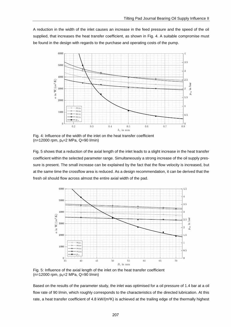
A reduction in the width of the inlet causes an increase in the feed pressure and the speed of the oil
supplied, that increases the heat transfer coefficient, as shown in Fig. 4. A suitable compromise must
be found in the design with regards to the purchase and operating costs of the pump.
Fig. 4: Influence of the width of the inlet on the heat transfer coefficient (n=12000 rpm, pq=2 MPa, Q=90 l/min)
Fig. 5 shows that a reduction of the axial length of the inlet leads to a slight increase in the heat transfer
coefficient within the selected parameter range. Simultaneously a strong increase of the oil supply pres-
sure is present. The small increase can be explained by the fact that the flow velocity is increased, but
at the same time the crossflow area is reduced. As a design recommendation, it can be derived that the
fresh oil should flow across almost the entire axial width of the pad.
Fig. 5: Influence of the axial length of the inlet on the heat transfer coefficient (n=12000 rpm, pq=2 MPa, Q=90 l/min)
Based on the results of the parameter study, the inlet was optimised for a oil pressure of 1.4 bar at a oil
flow rate of 90 l/min, which roughly corresponds to the characteristics of the directed lubrication. At this
rate, a heat transfer coefficient of 4.8 kW/(m²K) is achieved at the trailing edge of the thermally highest
207

Tilting Pad Journal Bearing Oil Supply Influence II
loaded pad. The temperature distribution in the bearing as well as the flow in the inlet region for the
optimized geometry is shown in Fig. 6. Fig. 7 shows the characteristic of the heat transfer coefficients
and the feed pressure for different oil flow rates. It can be seen that an increase of the oil flow rate leads
to an increase of the heat transfer coefficients at the same time. In the previous project Tilting Pad
Journal Bearing Oil Supply Influence I it could be shown that this behaviour cannot be observed con-
ventionally inlet designs such as directed lubrication by nozzles or spray bars directed to the journal.
Fig. 6: Optimized oil supply, temperature distribution and flow in the gaps
Fig. 7: Influence of the oil flow rate on the heat transfer coefficient
208

Tilting Pad Journal Bearing Oil Supply Influence II
2.2 Low heat transfer
A low heat transfer is generated by attaching an insulating layer at the trailing edge. An effective heat
transfer coefficient can be estimated in an analytical calculation by adding the area-related thermal re-
sistances. Using a 3 mm thick layer of polycarbonate with 𝑅𝑡ℎ′ = 0.015 𝑚²𝐾/𝑊 and 𝛼 =
1500 𝑊/(𝑚²𝐾), this coefficient is approximately:
𝛼𝑒𝑓𝑓 ≈1
1/𝛼+𝑅𝑡ℎ′ = 63.8
𝑊
𝑚2𝐾 (1)
This value is significantly below the level that could be achieved by a design related reduction of the
inflow velocity at the trailing edge. For better insulation, plastic screws are used instead of metal ones.
Fig. 8 shows a pad with the design implementation of this variant.
Fig. 8: Pad with attached insulating layer at the trailing edge
3 Study on heat transfer of the remaining pad free surfaces
Within the project, the heat transfer coefficients of the remaining pad free surfaces, i.e. the back and the
side faces, are also investigated. In a first step, the influence of the heat transfer coefficients of all four
pad surfaces on the maximum sensor temperature in the pad 𝑇𝑚𝑒𝑠𝑠,𝑚𝑎𝑥 was determined by means of a
parameter study in COMBROS R. For this purpose, one parameter was varied while the others were
kept constant. For 𝛼𝐿𝐸 and 𝛼𝑇𝐸 a value of 1500 W/(m²K) was assumed, for 𝛼𝑆𝐴 and 𝛼𝑆𝑅 a value of 500
W/(m²K) [2]. Fig. 9 shows the predicted maximum sensor temperature as a function of the particular
heat transfer coefficient.
209

Tilting Pad Journal Bearing Oil Supply Influence II
Fig. 9: Influence of the heat transfer coefficients on the max. measuring point temperature (n=12000 rpm, pq=2.0 MPa, Q=90 l/min)
The heat transfer coefficient at the trailing edge αTE exhibits the highest influence on the maximum
sensor temperature, while the heat transfer coefficient at the leading edge free pad surface αLE has no
distinct influence. This confirms the results from the previous project. The second largest influence
shows the heat transfer coefficient at the back of the pad αSR. The heat transfer coefficient at the side
surfaces is of minor importance similar to the one at the beginning of the pad. This can be explained on
the one hand by the large area of the pad’s back and on the other hand by its relative proximity to the
measuring point compared to the side surfaces.
In the CFD investigations described above and the ones of the previous project, heat transfers at the
leading edge and the trailing edge pad free surface, as well as their influence on the temperature
distribution in the pad were investigated in detail. For a complete description of the thermal behavior of
a tilting pad journal bearing, additional knowledge of the heat transfers at the remaining pad surfaces,
i.e. the pad side surfaces and the pad backs, is required. Here, CFD calculations of bearings with spray
bar and directed lubrication were carried out. Both variants are shown in Fig. 10. The coordinate system
is defined according to Fig. 1. Calculations for different operating conditions and the results were
evaluated. With regard to these flow forms, the oil supply can be divided into three domains: the domain
of the inlet region between the trailing edge of the upstream pad and the leading edge of the downstream
pad, the domain between the pad side surfaces and the baffle, and the region between pad back and
liner. The oil flow in these domains and the heat transfer at the adjacent pad surfaces will be discussed
in more detail in the following sections.
210

Tilting Pad Journal Bearing Oil Supply Influence II
Fig. 10: Geometry of the CFD models (left: directed lubrication, right: spray bar)
Side faces
The pads are radially fixed by axial pins in the baffle. The baffle also seals the inlet region. The test
bearing features a 3mm gap between pads and baffle. The flow in this region is visualized in Fig. 11 and
Fig. 12.
Fig. 11: Flow centred between side faces and pad retaining cover in the r-ϕ-plane at z=37,5mm
(directed lubrication, n=12000 rpm, Q=60 l/min, pq=2 MPa)
Fig. 12: Flow centred between side faces and pad retaining cover in the r-ϕ -plane at z=37,5mm
(directed lubrication at z=37,5mm (spray bar, n=12000 rpm, Q=60 l/min, pq=2 MPa)
Two significant flow components can be identified. On the one hand a flow in circumferential direction
exist that is induced by the rotation of the shaft and decreases in radial direction towards the liner. This
component is more distinctly present for directed lubrication variant than for the spray bar one, since the
spray bar fills almost the entire space between pad region and thus represents a throttling element.
1
2
3
4
1
2
3
4
u
u
211

Tilting Pad Journal Bearing Oil Supply Influence II
Fig. 13: Flow between side surfaces and pad retaining cover in the r- z-plane at ϕ=235°
(left: directed lubrication, right spray bar, n=12000 rpm, Q=60 l/min, pq=2 MPa)
The second flow component is directed axially and discharges the hot oil from the bearing particulary.
Both flows have a stochastic character and are overlaid by numerous vortices. In summary, a complex,
three-dimensional flow state exist.
The local heat transfer coefficient on the pad side surfaces is shown in Fig. 14 and Fig. 15 for directed
and spray bar lubrication. There is a strong local dependence of the heat transfer coefficient. It also
tends to be higher near the shaft and decreases in radial direction. However, no direct correlation to the
flow velocity distribution from Fig. 11 and Fig. 12 can be identified. Also a direct relationship between
the heat transfer coefficient and the wall shear stress, as the boundary layer theory suggests, could not
be found here.
Fig. 14: Heat transfer coefficient of the side surfaces (directed lubrication n=12000 rpm, pq=2 MPa, Q=60 l/min)
Fig. 15: Heat transfer coefficient of the side surfaces (spray bar n=12000 rpm, pq=2 MPa, Q=60 l/min)
Rear sides
The test bearing features a line contact between pad back and liner. The pad backs have an outer radius
of 68 mm, the liner an inner radius of 80 mm. If elastic deformations and surface roughness are ne-
glected, both surfaces touch each other in the line contact. However, this idealized contact cannot be
modeled in a flow simulation, as this would lead to invalid element skewness. A detailed resolution of
the contact would be very complex in the modeling procedure and would result in high computational
times. therefore, the contact region was modelled by keeping a minimum distance between pad back
and liner, that is in the order of magnitude of the surface roughness. This enables a complete meshing
of the pad back and describes at least in a first approximation the heat transfer in the contact area.
u
u
212
Tilting Pad Journal Bearing Oil Supply Influence II
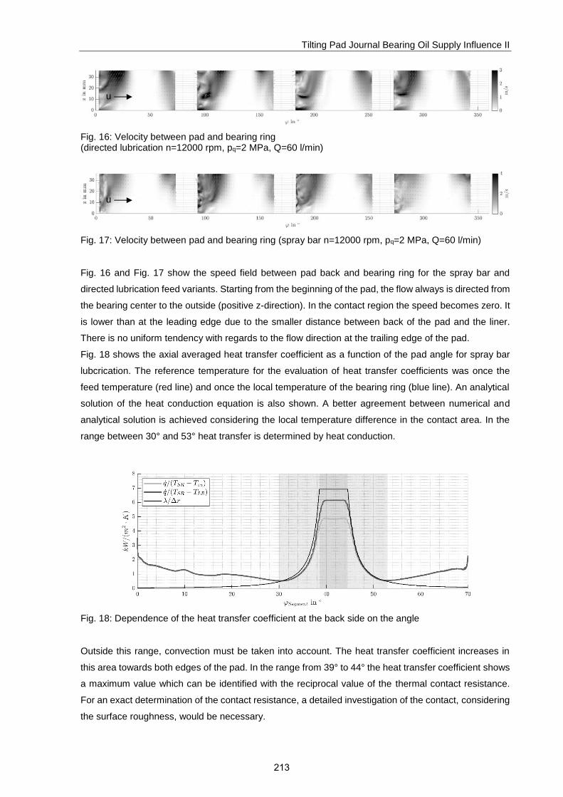
Fig. 16: Velocity between pad and bearing ring (directed lubrication n=12000 rpm, pq=2 MPa, Q=60 l/min)
Fig. 17: Velocity between pad and bearing ring (spray bar n=12000 rpm, pq=2 MPa, Q=60 l/min)
Fig. 16 and Fig. 17 show the speed field between pad back and bearing ring for the spray bar and
directed lubrication feed variants. Starting from the beginning of the pad, the flow always is directed from
the bearing center to the outside (positive z-direction). In the contact region the speed becomes zero. It
is lower than at the leading edge due to the smaller distance between back of the pad and the liner.
There is no uniform tendency with regards to the flow direction at the trailing edge of the pad.
Fig. 18 shows the axial averaged heat transfer coefficient as a function of the pad angle for spray bar
lubcrication. The reference temperature for the evaluation of heat transfer coefficients was once the
feed temperature (red line) and once the local temperature of the bearing ring (blue line). An analytical
solution of the heat conduction equation is also shown. A better agreement between numerical and
analytical solution is achieved considering the local temperature difference in the contact area. In the
range between 30° and 53° heat transfer is determined by heat conduction.
Fig. 18: Dependence of the heat transfer coefficient at the back side on the angle
Outside this range, convection must be taken into account. The heat transfer coefficient increases in
this area towards both edges of the pad. In the range from 39° to 44° the heat transfer coefficient shows
a maximum value which can be identified with the reciprocal value of the thermal contact resistance.
For an exact determination of the contact resistance, a detailed investigation of the contact, considering
the surface roughness, would be necessary.
u
u
213

Tilting Pad Journal Bearing Oil Supply Influence II
4 Development of a simplified model for the computation of HTCs
In the previously presented investigations, heat transfers at the pad surfaces were determined on the
basis of a detailed CFD model. For the calculation of tilting pad journal bearings in industrial practice, a
simplified model has to be developed that predicts heat transfer coefficients a priori.
For this purpose, the three-dimensional Navier-Stokes equations are solved numerically and a velocity
field is determined first. The calculation of the velocity field is carried out isothermally. The viscosity of
the lubricant is assumed to correspond to the fresh oil temperature. In the next step the energy equation
is solved using the previously determined velocity field. The calculation of the temperature is dimension-
less. The temperature on the pads is assumed to be constant. This allows the heat transfer coefficients
to be calculated in advance without knowing the actual temperature distribution. Likewise, the energy
equation does not have to be solved over the entire fluid domain, it is sufficient to solve the solution in
the area of the thermal boundary layer of the pad surfaces.
Momentum equation
The three components of the velocity field shall be determined by solving the momentum equation. The
numerical solution is conductedwith the finite volume method. The formulation in integral form is used:
∰𝜕(𝜌�⃗� )
𝜕𝑡𝑑𝑉 + ∯(𝜌�⃗� �⃗� 𝑇) ⋅ �⃗� 𝑑𝐴 = ∯ 𝝈 ⋅ �⃗� 𝑑𝐴 + ∰ 𝜌�⃗� 𝑑𝑉 (1)
The general momentum equation can be simplified for the application under consideration. The flow can
be assumed as stationary and incompressible, no volume forces occur:
𝜌 ∯(�⃗� �⃗� 𝑇) ⋅ �⃗� 𝑑𝐴 − ∯𝝈 ⋅ �⃗� 𝑑𝐴 = 0 (2)
The non-representational form stress tensor in the incompressible case is given by:
𝜎𝑖𝑗 = 𝜇 (𝜕𝑢𝑖
𝜕𝑥𝑗
+𝜕𝑢𝑗
𝜕𝑥𝑖
) − 𝑝𝛿𝑖𝑗 (3)
For the calculation of journal bearings, the representation in cylindrical coordinates is suitable. In this
case the stress tensor is:
𝝈 =
[ 2𝜇
𝜕𝑢
𝜕𝑟− 𝑝 𝜇 (
𝜕𝑣
𝜕𝑟+
1
𝑟
𝜕𝑢
𝜕𝜑) 𝜇 (
𝜕𝑤
𝜕𝑟+
𝜕𝑢
𝜕𝑧)
𝜇 (𝜕𝑣
𝜕𝑟+
1
𝑟
𝜕𝑢
𝜕𝜑)
2𝜇
𝑟
𝜕𝑣
𝜕𝜑− 𝑝 𝜇 (
1
𝑟
𝜕𝑤
𝜕𝜑+
𝜕𝑣
𝜕𝑧)
𝜇 (𝜕𝑤
𝜕𝑟+
𝜕𝑢
𝜕𝑧) 𝜇 (
1
𝑟
𝜕𝑤
𝜕𝜑+
𝜕𝑣
𝜕𝑧) 2𝜇
𝜕𝑤
𝜕𝑧− 𝑝
]
(4)
214

Tilting Pad Journal Bearing Oil Supply Influence II
Pressure equation
Another equation is necessary to determine the pressure. By introducing the continuity equation into the
momentum equation, the Poisson equation for the pressure can be obtained [4]. Here Δ denotes the
Laplace operator.
Δ𝑝 = −𝜌∇ ⋅ [∇(�⃗� �⃗� 𝑇 − 𝝈) − �⃗� +𝜕𝜌�⃗�
𝜕𝑡] (5)
By assuming a stationary, incompressible flow, this equation is simplified as follows:
Δ𝑝 = −𝜌Δ(�⃗� �⃗� 𝑇) (6)
Energy equation
The energy equation in its general form is:
𝜕𝜌𝐸
𝜕𝑡+ ∇ ⋅ (𝜌�⃗� 𝐻) = 𝜌 �⃗� ⋅ �⃗� + ∇ ⋅ (𝜎 ⋅ �⃗� − 𝜆∇𝑇) (7)
Considering the previous assumptions (stationary, incompressible, no volume forces), the energy equa-
tion can be simplified. Furthermore, the dissipation in the inlet region can be neglected. Thus the energy
equation represents a linear partial differential equation of 2nd order.
𝜌𝑐𝑝∇ ⋅ (�⃗� 𝑇) + 𝜆Δ𝑇 = 0 (8)
In cylindrical coordinates the equation is:
𝜌𝑐𝑝 [𝑢𝑟
𝜕𝑇
𝜕𝑟+ 𝑇
𝜕𝑢𝑟
𝜕𝑟+
𝑢𝑟𝑇
𝑟+
𝑢𝜑
𝑟
𝜕𝑇
𝜕𝜑+
𝑇
𝑟
𝜕𝑢𝜑
𝜕𝜑+ 𝑢𝑧
𝜕𝑇
𝜕𝑧+ 𝑇
𝜕𝑢𝑧
𝜕𝑧] + 𝜆 (
1
𝑟
𝜕𝑇
𝜕𝑟+
𝜕2𝑇
𝜕𝑟2+
1
𝑟2
𝜕2𝑇
𝜕𝜑2+
𝜕2𝑇
𝜕𝑧2) = 0
(9)
The numerical solution can be carried out using the finite difference method.
215

Tilting Pad Journal Bearing Oil Supply Influence II
Bibliography
[1] Radialkippsegmentlager-Ölzuführungseinfluss, Abschlussbericht, IGF Nr. 17373
[2] Dokumentation Radialgleitlagerberechnungsprogramm COMBROS R,
Dr.-Ing. Thomas Hagemann
[3] ANSYS CFX-Solver Theory Guide, ANSYS, Inc.
[4] Numerische Strömungsmechanik, J.H. Ferziger, M. Peric
216