r hydraulic leveling system - welcome to hwh … leveling system r. warning ! read the entire...
TRANSCRIPT

OPERATOR’S MANUAL
ML52447/MP04.338416AUG13
BI-AXIS Touch Panel ControlFEATURING:
HWH CORPORATION(On I-80, Exit 267 South)
2096 Moscow Road | Moscow, Iowa 52760Ph: 800/321-3494 (or) 563/724-3396 | Fax: 563/724-3408
www.hwh.com
R
Straight-Acting/Pivoting (Power-Extend/Spring-Retract) Jacks
R
RETRACT
EXTEND
HWH COMPUTERIZED LEVELING
SECURELY BEFORE REMOVING TIRES OR CRAWLING UNDER VEHICLE.UNDERSTAND OPERATOR’S MANUAL BEFORE USING. BLOCK FRAME AND TIRES
CANCEL
STOREAUTO
AUTOLEVEL
TRAVEL
BRAKE
MODE
WARNING!
EXCESSSLOPE
NOT INPARK/
R
MANUAL
RETRACT
EXTEND
CORPORATIONWH H
R
Pilot Air DumpTwo HWH SpaceMaker Slide-Out SystemsR
DUMPMANUAL
AP52446
HWH 725 Series, Computer-Controlled Hydraulic Leveling System
R

WARNING !
READ THE ENTIRE OPERATOR MANUAL BEFORE OPERATING.
BLOCK FRAME AND TIRES SECURELY BEFORE CRAWLING UNDER VEHICLE. DO NOT USE LEVELING JACKS OR AIR SUSPENSION TO SUPPORT VEHICLE WHILE UNDER VEHICLE OR CHANGING TIRES. VEHICLE MAY DROP AND/OR MOVE FORWARD OR BACKWARD WITHOUT WARNING CAUSING INJURY OR DEATH.
WEAR SAFETY GLASSES WHEN INSPECTING OR SERVICING THE SYSTEM TO PROTECT EYES FROM DIRT, METALCHIPS, OIL LEAKS, ETC. FOLLOW ALL OTHER APPLICABLE SHOP SAFETY PRACTICES.
OPERATOR’S MANUAL
KEEP ALL PEOPLE CLEAR OF VEHICLE WHILE DUMPING AIR FROM THE VEHICLE’S SUSPENSION.
DO NOT MOVE THE VEHICLE IF THE VEHICLE IS NOT AT THE PROPER RIDE HEIGHT. CONTACT MANUFACTURER
IMPORTANT: IF COACH IS EQUIPPED WITH A ROOM EXTENSION, READ ROOM EXTENSION SECTION BEFOREOPERATING LEVELING SYSTEM.
08APR10MP14.0014
TECHNICAL SERVICE FOR MOVING THE VEHICLE WHEN NOT AT THE PROPER RIDE HEIGHT.
KEEP ALL PEOPLE CLEAR OF VEHICLE WHILE OPERATING LEVELING SYSTEM OR ROOM EXTENSIONS.
HWH maintains technical and information services at 800-321-3494 or563-724-3396. Assistance is available Monday thru Friday from 8:00A.M until 5:00P.M. C.S.T.
Technical and information service is also available on-line at www.hwh.com.

MP24.315107JUN10
"CANCEL" BUTTON:any leveling system operation.
"AUTO LEVEL" BUTTON:
"AUTO STORE" BUTTON:four jacks at the same time. WARNING LIGHTS:
"EXCESS SLOPE" LIGHT:the leveling system cannot level the vehicle.
"NOT IN PARK/BRAKE" LIGHT:when the hand/auto brake is not set and the "AUTO LEVEL"
"TRAVEL MODE" LIGHT:when the ignition is on, when the jacks are retracted and there are no red WARNING lights on.
MASTER "JACKS DOWN" WARNING LIGHT:light mounted in the dash separate from the touch panel.
and the ignition is "ON".
BUZZER:
CONTROL FUNCTIONS
INDICATOR LIGHTS (CONTINUED)CONTROL BUTTONS
Push this button to stop
Push this button to retract all
This indicator will light when
This indicator will light
This indicator light will be on
This is a
This is a jacks down warning.
EXTEND BUTTONS (UP ARROWS):
RETRACT BUTTONS (DOWN ARROWS):
LEVELING LIGHTS:
These buttons will extend their respective jack pairs to lift the vehicle.
These buttonswill retract their respective jack pairs to lower the vehicle.
The four yellow indicating lights are level sensing indicators. When a yellow light is on, it indicates that its side, end, or corner of the vehicle is low. No more than two lights should be on at the same time.Push this button any time to
The four red lights surrounding the yellow level indicators are jacks down WARNING lights. They are functional only when the ignition is in the "ON"
extended 1/4 to 1/2 inch.
start the automatic leveling function.
It will sound if the master "JACKS DOWN"
CONTROL IDENTIFICATION
725 SERIES LEVELING SYSTEM
COMPUTER-CONTROL
or "ACC" position, the system is on, and the jacks are
It will be on when any one or more jacks are extended
button is being pushed.
RETRACT
EXTEND
HWH COMPUTERIZED LEVELING
SECURELY BEFORE REMOVING TIRES OR CRAWLING UNDER VEHICLE.UNDERSTAND OPERATOR’S MANUAL BEFORE USING. BLOCK FRAME AND TIRES
"EXCESS SLOPE"Indicator light
"AUTO LEVEL"
AUTO LEVEL/STORECANCEL Button
"NOT IN PARK"Indicator light
Indicator light
"TRAVEL MODE"Indicator light
Indicator light
AUTO LEVEL
"AUTO STORE"Button
STORE
Button
RAISE LEFT SIDEManual button
LOWER LEFT SIDEManual button
STOREAUTO
CANCEL
AUTOLEVEL
TRAVEL
BRAKE
MODE
WARNING!
EXCESSSLOPE
NOT INPARK/
R
LOWER FRONTManual button
RAISE FRONTManual button
JACK DOWNIndicator light
RAISE RIGHT SIDEManual button
LOWER RIGHT SIDEManual button
LEVEL SENSINGIndicator light (4) yellow
RAISE REARManual button
LOWER REARManual button
MANUAL
RETRACT
EXTEND
(4) red
INDICATOR LIGHTS
AUTO LEVEL INDICATOR LIGHT: This light will flashduring the automatic leveling function.
STORE INDICATOR LIGHT: This light will flash duringthe automatic store function.
When all four yellow LEVEL lights are out, the vehicle islevel.
MANUALDUMP
"MANUAL DUMP"Button
warning light is on.
"MANUAL DUMP" BUTTON: This is a manual button fordumping air from the vehicle suspension.

MP25.999514MAR12
CONTROL IDENTIFICATION
PUMP RUN TIME
SYSTEM VARIATIONS FOR PUMP RUN TIME
Contact HWH corporation to get specific information about the system in this vehicle.
No matter what HWH system is on the vehicle, the pump should not be ran for more than four minutes (3" motors) or six minutes (3.7" or 4.5" motors) without allowing the pump motor to cool for thirty minutes. Continuous operation of the pump motor without allowing the motor to cool can damage the pump motor.
Some HWH systems are equipped with a lighted reset switch. If the processor turns the pump off because the run time has been exceeded, the light in the reset switch will turn on. The
With some systems, when the processor has turned the pump off because the run time has been exceeded, power to the HWH system must be turned off and back on before the system will operate. With motorized vehicles, turn theignition off and back on. With non-motorized vehicles, turn the master power switch for the HWH system off and back
DO NOT continue without allowing the pump motor to cool for thirty minutes.
When operating some leveling systems manually or operating the room extensions, the pump will turn off and back on while pushing the control button when the pump run time has been exceeded.the pump motor to cool for thirty minutes.
Some systems can be turned back on immediately after the processor turns the pump off.back on or run the pump without allowing the pump motor to cool for thirty minutes.
Some systems with rooms run the rooms separate from the system processor. These systems do not monitor pump run time when operating the rooms.pump motor to cool for thirty minutes.
The HWH systems with a computer processor monitor the pump run time and will turn the pump off if the run time exceeds a specified time. This time can vary with different systems. Due to available electronics or system design, the pump run time programs will also vary. Leveling systems and room extensions that are not controlled by a system processor have no pump run time protection.thirty minutes.
Pump motors used with HWH leveling systems and room extension systems come in 3 different diameters; 3", 3.7" and 4.5". Contact the vehicle manufacturer or HWH for help with identifying the motor size.runs for more than four minutes with a 3" motor; or six minutes with a 3.7" or 4.5" motor that the motor is allowed to cool for thirty minutes before continuing. Continuous operation of the pump motor without allowing the motor
PUMP RUN TIME
It is important that any time the pump
to cool can damage the motor.
DO NOT run the pump more than four or six minutes without allowing the pump motor to cool for
DO NOT run the pump more than four or six minutes without allowing the
DO NOT turn the system
DO NOT continue without allowing
on.
system will not operate until the reset switch is pushed.DO NOT continue without allowing the pump motor to cool for thirty minutes.
LIGHTED RESET SWITCH
For cold weather information see "COLD WEATHER OPERATIONS" below.
COLD WEATHER OPERATIONS
HWH leveling and room extension systems are designed to function in cold weather down to 0 degrees Fahrenheit. Below freezing (32 degrees Fahrenheit) the jacks or rooms will operate slower than usual.
For operation in temperatures dropping below -20 degrees Fahrenheit, it is necessary that the system is equipped with oil designed for extreme cold weather application such as a synthetic oil. (Contact HWH for recommendations.)
DO NOT run the pump motor continuously.
Continuous operation of the pump with slow moving jacks or rooms in cold weather, without allowing the pump motor tocool will cause the pump motor to burn up and damage the pump assembly.
It is important that any time the pump runs for more than four minutes
continuing. Continuous operation of the pump motor without allowing the motor to cool can damage the motor. with a 3" motor; or six minutes with a 3.7" or 4.5" motor that the motor is allowed to cool for thirty minutes before

OPERATING PROCEDURES
MP34.023207AUG13
GENERAL INSTRUCTIONS
PREPARATION FOR TRAVEL
If parking on soft ground or asphalt paving, a wood block orpad should be placed under each jack.
Any time a hydraulic leveling process is interrupted, it is recommended to retract the jacks according to the JACK RETRACTION Section and then restart the leveling process.
If the hand / auto brake is not set when the "AUTO LEVEL" button is pressed, the "NOT IN PARK/BRAKE" light will come on. When the "AUTO LEVEL" button is released the
If the jacks are retracted but a red "WARNING" light is lit the system needs to be serviced.
If the jacks cannot be retracted according to the JACKRETRACTION Section, retract the jacks according to theMANUAL JACK RETRACTION Section. The system should then be checked.
Maintain adequate clearance in all directions for vehicle, roomextensions, awnings, doors, steps, etc. Vehicle may move inany direction due to jacks extending or retracting, settling of the jacks or the vehicle, equipment malfunction, etc..
Any room extension or generator slide should be fully
DO NOT MOVE THE VEHICLE IF ONEOR MORE JACKS ARE EXTENDED TO THE GROUND.WARNING:
"NOT IN PARK/BRAKE" light will go out. The Automatic
retracted before traveling.
Leveling function will not start.
Press the "CANCEL" button or turn the ignition switch "OFF" at any time to stop the operation of the system.
fail to retract completely, extend the jacks back downto the ground then retract the jacks again.
NOTE: If the vehicle is parked or stored with the jacksextended for an extended period of time and the jacks
IMPORTANT: Before traveling, the red jack warning lights must be off the "TRAVEL MODE" light must be onand the vehicle should be at the proper height for travel. If lights are not correct for travel, retract jack as
THE LEVELING JACKS ARE STILL IN CONTACT WITH THE GROUND OR IN THE EXTEND POSITION. THIS VEHICLE IS EQUIPPED WITH STRAIGHT-ACTING JACKS.MOVING THE VEHICLE WITH THE LEVELING JACKSEXTENDED CAN CAUSE SEVERE DAMAGE TO THE
WARNING: DO NOT MOVE THE VEHICLE WHILE
TRAVELING. CONTACT MANUFACTURER TECHNICALSERVICE BEFORE MOVING A VEHICLE THAT IS NOT AT PROPER TRAVEL HEIGHT.
VEHICLE IS AT THE PROPER RIDE HEIGHT FOR INTO THE STORE/TRAVEL POSITION AND THE
JACKS AND OR THE VEHICLE AND CREATE A DRIVING
HAZARD. DO NOT RELY SOLELY UPON WARNINGLIGHTS. IT IS THE OPERATOR’S RESPONSIBILITYTO CHECK THAT ALL JACKS ARE FULLY RETRACTED
described in the JACK RETRACTION Section.
MP34.275127APR15
OPERATING PROCEDURES
725 SERIES LEVELING SYSTEM
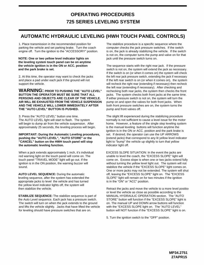
or level the vehicle as close as possible according to the Retract the jacks and move the vehicle to a more level position
SLOPE" light will remain on for two minutes if the ignition
One or more jacks may not be extended. The system will shutstabilize the vehicle if the "EXCESS SLOPE" light comes on. without turning the yellow level light out. The system will not come on. Excess slope is when one or two jacks extend fully unable to level the coach, the "EXCESS SLOPE" light willEXCESS SLOPE SITUATION: In the event the jacks are
AUTOMATIC HYDRAULIC LEVELING (HWH TOUCH PANEL CONTROLS)
the vehicle ignition is in the ON or ACC. position the leveling system touch panel can be on anytime NOTE: One or two yellow level indicator lights on
the automatic leveling function."CANCEL" button on the HWH touch panel will stoppushing the "AUTO LEVEL", "AUTO STORE" or the IMPORTANT: During the Automatic Leveling procedures,
and place a pad under each jack if the ground will not 2. At this time, the operator may want to check the jacks
engine off. Turn the ignition to the "ACCESSORY" position.parking the vehicle and set parking brake. Turn the coach 1. Place transmission in the recommended position for
and the park brake is set.
support the vehicle.
MANUAL HYDRAULIC OPERATION section. The "AUTO
is in the "ON" or "ACC" position.
off, leaving the "EXCESS SLOPE" light on. The "EXCESS
5. Turn the ignition switch to the "OFF" position.
The slight lift experienced during the stabilizing procedure normally is not sufficient to cause a level issue for the motor home. However, a feature of the single step leveling system is the manual leveling buttons will function anytime the ignition is in the ON or ACC. position and the park brake is set. If desired, the operator can use the UP ARROWS (extend jacks) that correspond to any lit yellow level indicator light to "bump" the vehicle up slightly to turn that yellow indicator light off.
During the automatic leveling sequence, after the system has extended the appropriate jacks to level the vehicle and has turned the yellow level indicator lights off, the system will then stabilize the vehicle.
The switch will turn on when the jack extends to the groundand lifts the vehicle slightly. Jacks that have lifted the vehiclefor leveling should have pressure switches that are on.
The sequence starts with the right rear jack. If the pressureswitch is not on, the system will extend the jack as necessary.If the switch is on (or when it comes on) the system will checkthe left rear jack pressure switch, extending the jack if necessaryIf the left rear switch is on (or when it comes on), the system will recheck the right rear (extending if necessary) then recheckthe left rear (extending if necessary). After checking and rechecking both rear jacks, the system then checks the front jacks. The system checks both front jacks at the same time. If either pressure switch is not on, the system will turn the pump on and open the valves for both front jacks. Whenboth front pressure switches are on, the system turns the pump and front valves off.THE "AUTO LEVEL" BUTTON IS PUSHED.
AIR WILL BE EXHAUSTED FROM THE VEHICLE SUSPENSIONAND THE VEHICLE WILL LOWER IMMEDIATELY AFTER
BUTTON THE OPERATOR MUST BE SURE THAT ALLPERSONS AND OBJECTS ARE CLEAR OF THE VEHICLE.
will begin to dump air from the vehicle suspension. Afterapproximately 25 seconds, the leveling process will begin.
The AUTO LEVEL light will start to flash. The system3. Press the "AUTO LEVEL" button one time.
WARNING: PRIOR TO PUSHING THE "AUTO LEVEL"
When a jack extends approximately 1 inch, it’s individualred warning light on the touch panel will come on. Thetouch panel "TRAVEL MODE" light will go out. If theignition is in the ON position, the warning buzzer willsound.
AUTO LEVEL SEQUENCE:
STABILIZE SEQUENCE: The stabilize sequence is part ofthe Auto Level sequence. Each jack has a pressure switch.
on. The manual UP and DOWN arrow buttons will function with the "EXCESS SLOPE light on. The "AUTO LEVEL"button will NOT function if the "EXCESS SLOPE" light is on.
jack until the pressure switch turns on.is not on, the computer turns the pump and valve on for that is on, the jack is already stabilizing the vehicle. If the switch computer checks the jack pressure switches. If the switchThe stabilize procedure is a specific sequence where the
STORE" button will function if the "EXCESS SLOPE" light is

MP34.306115FEB11
WARNING:
JACK RETRACTION (HWH TOUCH PANEL CONTROLS)
THE OPERATOR MUST BE SURE THATTHERE ARE NO OBJECTS UNDER THE VEHICLE AND THATALL PEOPLE ARE CLEAR OF THE VEHICLE.
3. If jacks cannot be retracted by the above procedure seeMANUAL JACK RETRACTION Section.
WARNING: DO NOT MOVE THE VEHICLE WHILE THELEVELING JACKS ARE STILL IN CONTACT WITH THE GROUNDOR IN THE EXTEND POSITION. THIS VEHICLE IS EQUIPPEDWITH STRAIGHT-ACTING JACKS. MOVING THE VEHICLEWITH THE LEVELING JACKS EXTENDED CAN CAUSESEVERE DAMAGE TO THE JACKS AND OR THE VEHICLE ANDCREATE A DRIVING HAZARD. DO NOT RELY SOLELY UPONWARNING LIGHTS. IT IS THE OPERATOR’S RESPONSIBILITY TOCHECK THAT ALL JACKS ARE FULLY RETRACTED INTO
2. The vehicle can be moved as soon as the red warning lights are out, the jacks are in the STORE/TRAVEL positionand the green "TRAVEL" light is on, if the vehicle is at the
THE STORE/TRAVEL POSITION AND THE VEHICLE IS AT
OPERATING PROCEDURES
725 SERIES LEVELING SYSTEM
NOTE: When traveling thermal expansion may cause a jack to extend slightly. When the "AUTO STORE" button has been used to retract the jacks, the system will automatically retract any jack that extends due to thermal expansion.
IMPORTANT: If a red warning light and buzzer come onwhile traveling, the jacks should be checked as soon asa safe parking location is found.
NOTE: When the jacks are stored with the ignition inthe ON position, the warning buzzer will sound untilthe jacks have retracted to the STORE position. Ifdesired, the jacks can be stored with the ignition keyin the accessory position. This will eliminate the warning buzzer while the jacks are retracting.
1. Start the engine and press the "AUTO STORE" button.The store indicator light will flash. The vehicle should start to return to proper ride height. The front jacks will retract for 5 seconds before the rear jacks will begin to retract. As each jack retracts, its red WARNING light will go out. The system will automatically shut down 1 minute after the four individual red "WARNING" lights are out. If any one red "WARNING light does not go out, the system will continue to store for fifty minutes, then shut down regardless of the "WARNING" lights
the automatic store function."CANCEL" button on the HWH touch panel will stoppushing the "AUTO LEVEL", "AUTO STORE" or the IMPORTANT: During the Automatic Store procedures,
IMPORTANT: If power to the system is interrupted after starting a store procedure with either the touch panel or the remote rocker switch, the store
procedure should be reinitiated and the jacks should be completely retracted with all four red WARNING lights out prior to traveling.
condition.
THE PROPER RIDE HEIGHT.
proper ride height for traveling.
It is recommended to retract any room extensionsbefore retracting the jacks.

OPERATING PROCEDURES
MP34.333307AUG13
IMPORTANT: Do not continue to push an EXTEND
MANUAL JACK RETRACTION
MANUAL HYDRAULIC OPERATION
1. Place transmission in the recommended position for parking
2. Place pads under the jack feet if the ground will not supportthe vehicle on the jacks.
4. The vehicle may be leveled using the manual EXTEND (UP ARROW) buttons on the right half of the panel. If a yellow LEVEL SENSING light is on, that side, end or corner of the
Jacks will extend (or retract) in pairs to raise (or lower) a side or end of the vehicle.
button for more than ten (10) seconds after that pair of
5. When leveling is completed, turn the ignition switch to the "OFF" position.
the vehicle, and set the parking brake. Turn the ignition to the"ACCESSORY" position.
jacks are fully extended.
large and / or small valves.NOTE: Assemblies can have different combinations of
release for retracting only if the "AUTO STORE" button on theequipped with a manual valve release. Use the manual valve The solenoid valves on the power unit valve assembly are
DO NOT CRAWL UNDER THE VEHICLE, KEEP A SAFEDISTANCE IN FRONT AND REAR OF THE VEHICLE.THE VEHICLE MAY DROP AND/OR MOVE FORWARD OR BACKWARD WITHOUT WARNING AS THE VALVERELEASE IS OPERATED.
1. Locate the manual valve release on each solenoid valve.The solenoid valves are located on the power unit/valve
2. Allow clearance for the vehicle to lower.
assembly.
WARNING: KEEP AWAY FROM THE WHEELS,
5. Check that all four jacks are now retracted.
6. Close the valves by moving the valve release cam to
7. The system should now be repaired before using again.
3. Retract the front jacks by slowly opening the two center valves.
4. Repeat the process for the rear jacks by opening the two
the closed position.
outer valves.
vehicle is low. It is best to level the vehicle side to side first, if needed, before front to rear.
Any jack not used for leveling can be extended to the ground. This provides additional stability against wind and activity in the vehicle. Jacks used to stabilize the vehicle after leveling is complete should lift the vehicle slightly after touching the ground.
BREATHER
RELEASE CAMWITH VALVESMALL STYLE
MANIFOLD
CAP
from the vehicle suspension.3. Push the "DUMP" button. Wait until all air is exhausted
CLOSEDVALVE
OPEN
VALVE RELEASE CAMLARGE STYLE WITH
CLOSEVALVE
OPENED
VALVE RELEASE CAM OPERATION
control panel will not retract the jacks for travel.
Large and small valves will be equipped with a valverelease cam. The cam might be rotated in any direction on the valve. Pushing the release cam in the wrong direction may damage the valve.

OPERATING PROCEDURES
ROOM EXTEND PROCEDURE
2. Unlock all room-locking devices.
to the room or has been used, remove it before
WARNING:
extend the room.
3. To extend the room, press and hold the ROOMCONTROL in the "EXTEND" position until the room is fully
halt the operation of the room.
KEEP PEOPLE AND OBSTRUCTIONSCLEAR OF ROOM WHEN OPERATING.
NOTE: If a MANUAL RETRACT DEVICE is attached
NOTE: Make sure there is adequate clearance to fully
NOTE: Releasing the ROOM CONTROL will
NOTE:
1. The ignition must be in the "ACC" or "ON" position
The park brake must be set before a room can be extended or retracted.
is fully extended or stops moving."EXTEND" position for more than ten seconds after the room
of the room, do not reverse direction of the room until
after the room is fully extended. This assures proper Hold the control to "EXTEND" three or four seconds
pressurization of the cylinders.
Do not hold the ROOM CONTROL in theIMPORTANT:
NOTE:
During normal operation
the room is fully extended. If necessary, the direction of the room may be reversed, but watch for binding of the room. If the direction of the room has been reversed, DO NOT re-extend the room until the room has been fully retracted.
stops moving, release the room control immediately.DO NOT force the room. DO NOT reverse direction of
1-800-321-3494.
MP34.434324NOV15
DISENGAGED BEFORE OPERATING THE ROOM.RETRACTING DEVICES ARE DETACHED ORALL ROOM LOCKING, CLAMPING OR MANUALOPERATOR’S RESPONSIBILITY TO ENSURE THATPERSONAL INJURY AND VEHICLE DAMAGE. IT IS THEDEVICES ATTACHED OR ENGAGED CAN CAUSEROOM LOCKING, CLAMPING OR MANUAL RETRACTING WARNING: OPERATING A ROOM WITH ANY
It is recommended to complete the Leveling Procedurebefore operating room extensions.
to operate the room.
IMPORTANT: Room controls are provided by the vehiclemanufacturer. Refer to the vehicle manufacturer forinformation concerning the room controls. The followinginformation is basic room operating information. Readthis information carefully before operating the rooms.
extending the room.
If either side of the room
the room, contact HWH Customer Service for assistance
IMPORTANT: Do not use a room extension supportwhen the vehicle is supported by the leveling system.
extended.

OPERATING PROCEDURES
ROOM RETRACT PROCEDURE
2. To retract the room press and hold the ROOM CONTROLin the "RETRACT" position until the room is fully retracted.
halt the operation of the room.
3. Engage all room-locking devices.
IMPORTANT: Room-locking devices should be locked while traveling.
WARNING:CLEAR OF ROOM WHEN OPERATING.
KEEP PEOPLE AND OBSTRUCTIONS
4. If the room will not retract see the MANUAL ROOM RETRACT PROCEDURE.
NOTE:
NOTE:NOTE: Releasing the ROOM CONTROL will
The park brake must be set before a room can beextended or retracted.
HWH Customer Service for assistance 1-800-321-3494.DO NOT reverse direction of the room, contact room control immediately. DO NOT force the room.If either side of the room stops moving, release the room is fully retracted or stops moving."RETRACT" position for more than ten seconds after the
Do not hold the ROOM CONTROL in the
reversed, DO NOT retract the room until the room the room. If the direction of the room has been of the room may be reversed, but watch for binding of the room is fully retracted. If necessary, the direction of the room, do not reverse direction of the room until
During normal operation
Hold the switch to "RETRACT" three or four secondsafter the room is fully retracted. This assures proper
has been fully extended.
pressurization of the cylinders.
IMPORTANT:
NOTE:
MP34.454315FEB11
It is recommended to retract room extensionsbefore retracting jacks.
to operate the room.1. The ignition must be in the "ACC" or "ON" position
this information carefully before operating the rooms.information is basic room operating information. Readinformation concerning the room controls. The followingmanufacturer. Refer to the vehicle manufacturer forIMPORTANT: Room controls are provided by the vehicle

OPERATING PROCEDURES
MP34.949015FEB11
MANUAL ROOM RETRACTION PROCEDURES
GENERAL INFORMATION
Most rooms can be retracted manually in the case of amechanical or electrical failure. Some HWH mechanismshave a built in manual retract mechanism. Some roomscan be retracted through the use of some type of winchingmechanism. Some mechanisms, especially with smallerrooms, can simply be pushed in after the solenoid valveshave been opened. Refer to other pages in this manualfor specific manual room retract information. If informationis not available in this manual, contact the vehiclemanufacturer or HWH Customer Service for assistance.HWH Customer Service hours are Monday throughFriday 8:00AM until 5:00PM Central time.
Note: Contact the vehicle manufacturer for informationconcerning the storage of any manual retract devicesor winches. Refer to the vehicle manufacturer forinformation to connect a winch or other retract devicethat is not built into the mechanism. Also contact thevehicle manufacturer for manual room retractprocedures for any winch or retracting device notsupplied by HWH or in the event no retract deviceis supplied with the vehicle.
WARNING: USE EXTREME CAUTION WHENUSING A MANUAL RETRACT WINCH.
When manually retracting rooms, it is recommended thatleveling jacks be retracted, when possible, before retractingthe rooms.
To manually retract a room, it is necessary to determinewhich extend and retract solenoid valves are assigned tothe room. Refer to available diagrams or the vehiclemanufacturer for valve location. If the information is notreadily available, it is permissible to open all of the roomextension valves.
To manually retract a room both the cylinder extend andcylinder retract valves should be opened.
The room extension manifold has valves equipped withvalve release nuts or valve release cams.
For valves with release nuts, open the valve by turningthe 1/4" release nut counter clockwise. Use a 1/4" nutdriver or the nut driver incorporated into the breathercap. DO NOT turn the release nuts more than 4 and1/2 turns. Turning the nuts more could damage thevalve. When closing the valves, make snug only.DO NOT over tighten the nuts.
For valves with release cams, simply move the camto the open position. The release cam might be rotatedin any position on the valve. Moving the cam in thewrong direction can damage the valve.
MANIFOLD NOT SHOWN - ROOM EXTENSION MANIFOLDMAY BE MOUNTED SEPERATE FROM PUMP
ROOM
MANIFOLDEXTENSION
VALVE WITHRELEASE CAM
VALVE
HYDRAULIC PUMP/MANIFOLD - LEVELING SYSTEM
RETRACTCYLINDER
VALVE
CYLINDEREXTEND
VALVE WITH1/4" RELEASE NUT
BREATHERCAP
OF THE RELEASE CAM ALONG WITHTHE PROPER MOTION TO OPEN OR
CLOSE THE VALVE
IT IS IMPORTANT TO NOTE THE SHAPE
VALVE RELEASE CAM OPERATION
CLOSETO
TO OPENVALVEOPENED
VALVECLOSED

"UNIVERSAL STRAIGHT OUT" ROOM EXTENSION MECHANISM
MANUAL ROOM RETRACTION PROCEDURES - VALVES WITH RELEASE CAMS
MP34.956815FEB11
OPERATING PROCEDURES
PLATERECEIVER
RODTHREADED
ROOM EXTENDED
THREADEDBLOCK
ROOM RETRACTED
BLOCKTHREADED
THREADEDROD
manufacturer.
the front and one for the rear mechanism should be provided.2. Start both threaded rods until resistance is met, one for
HYDRAULIC PUMP/MANIFOLD
NOTE: The valve release cam might be rotated in any
NOTE: To access the threaded blocks refer to vehicle
release cam to the open position.for the extend and retract solenoid valves by moving the valveassigned to the room. Manually open the valve release nuts1. Determine which extend and retract solenoid valves are 4. Move to the other room extension mechanism, rotate
the room, contact HWH Customer Service for assistance understood or if the room begins to bind DO NOT force IMPORTANT: If at any stage something is not
6. Repeat steps 4 and 5 alternating from mechanism to mechanism rotating each threaded rod 12 completeturns until room is sealed. (DO NOT exceed 15
5. Return to the first room extension mechanism and rotate the threaded rod clockwise 12 complete turns.
the threaded rod clockwise 12 complete turns.
ft.lbs) Make sure the room does not bind.
1-800-321-3494.
Do Not use an impact wrench.
either mechanism’s threaded rod clockwise 6 complete turns.a personal wrench or a tire iron with a 1-1/8" opening rotate 3. Using wrench provided, threaded rods impact the coach wall or the mechanism.
Be careful to not extend the room so far that the threaded rods out and slightly extending the room. threaded rods completely, alternate backing the NOTE: If there is not enough room to remove both
ROOM HAS BEEN SERVICED. ANY SOLENOID VALVES
RODS SHOULD BE COMPLETELY REMOVED.LEFT OPEN SHOULD BE CLOSED AND THE THREADED
IMPORTANT: DO NOT EXTEND THE ROOM UNTIL THE
threaded rods in place until the room has beenNOTE: Leave the solenoid valves open and the
serviced.
SOLENOID VALVES
CLOSEVALVE
OPENED
TO
TO OPEN
VALVECLOSED
direction on the valve. Pushing the release cam in thewrong direction could damage the valve.

MAINTENANCE
MP44.001813NOV17
OIL LEVEL
ELECTRICAL SYSTEM
The batteries should be in good condition and fully charged.Weak batteries can cause erratic operation. Battery cable terminals and battery posts and connections should be kept
All electrical connections, especially ground connections, should be clean, tight, free from corrosion and protected
JACKS
There are very few user serviceable parts on the jacksThe jacks require very little maintenance. If the jacks are
VISUAL INSPECTION
Periodically inspect the system for oil leaks and damaged or missing parts, such as pivot bolts or springs.Check the hydraulic lines and wiring for damage and wear. Check that the jacks do not interfere with any parts of the vehicle when they are in the "STORE" position.
The system will operate better if kept clean and free from caked on mud or ice.
OPERATIONAL CHECK
Check that all lights work according to the "INDICATOR LIGHT" Section. Correct function of the red "WARNING"
Review the OPERATOR MANUAL. Run the system according to the SYSTEM OPERATION Section. Note any abnormal operation.
Review the "JACK RETRACTION" Section. Make sure the jacks will fully retract to the "STORE" position. Jacks should not interfere with any of the coach when in the "STORE"
clean.from weathering.
light is important.
position.
extremely dirty with caked on mud they should be washed.
If extremely dirty, the jack rods should NOT be wiped. The jack rods do not need to be oiled or sprayed with anything.
ROOM EXTENSIONS
The HWH room mechanisms need no maintenance.DO NOT grease or lubricate any parts of the HWHmechanism.
Any visible mechanism can be kept clean by washingwith water. Refer to the vehicle manufacturer forcorrect maintenance of the room seals.
See ML47149 for proper maintenance of all jacks.
cap before removing.
and steps should be fully retracted before checking fluid
breather cap. Clear any dirt away from the breather / fillerassembly. The oil level is checked and filled through thelevel. The oil reservoir is part of the pump / manifold
Any HWH hydraulic equipment, including jacks, slide-outs
servicing of the coach.All maintenance should be done as part of the normal
there is an oil leak in the system.purchased and then once every two years. More often if The oil level should be checked when the vehicle is first
should be between the bottom of the dipstick and thereservoir. Most breather caps have a dipstick. Fluid levelThe oil level should be within one inch of the top of the
emergency Dexron automatic transmission fluid can be used.Dexron automatic transmission fluid contains red dye
and can cause staining should a leak occur. DO NOT USEbrake fluid or hydraulic jack fluid. Use of these can damage
HWH Specialty Hydraulic Oil is recommended. In an
NOTE: Overfilling the tank can cause leakage of oil through the breather cap.
center mark.
FLUID:
NOTE:
seals.

MAINTENANCE
NOT IN PARK/BRAKE CHECK
Apply the brake so the coach cannot roll. Turn the ignitionto the "ACC" or "ON" position. Release the parking brake.
THE COACH WHEELS SECURELY SO THE COACH CANNOT ROLL FORWARD OR BACKWARD.
WARNING: WHEN MAKING THIS CHECK, BLOCK If any of the above checks or inspections reveal a problem or if there are other problems or questions, consult a qualified RV repair center, your vehicle or coach manufacturer, or HWH CORPORATION
22NOV16MP44.0502
Push the "AUTO LEVEL" button. The "NOT IN PARK/BRAKE" indicator light should come on while the "AUTOLEVEL" button is pushed. Release the "AUTO LEVEL"
for service or repair.
button and set the park brake. The leveling systemshould now function.
WINTER WEATHER DRIVING
have dried. This can facilitate corrosion of metalliccontinue to absorb moisture from the air even after theyAnti-icing / deicing agents when splashed on your vehicle,
components, such as HWH jacks.
To help reduce the corrosion of jacks after exposure to anti-icing / deicing agents, thoroughly wash jacks with warmsoapy water.

SENSING UNIT MAINTENANCE/SERVICE
SENSING UNIT ADJUSTMENT / WITH ADJUSTING ENHANCEMENT
NOTE: If opposing LED’s are lit, there is a problem withthe Sensing Unit.
If LED (A) is lit: Tighten adjustment screw number 1until the LED is off.
If LED (C) is lit: Loosen adjustment screw number 1until the LED is off.
If LED (B) is lit: Loosen adjustment screw number 3until the LED is off.
until the LED is off.If LED (D) is lit: Tighten adjustment screw number 3
09NOV10MP44.1511
With the vehicle level according to the bubble level, if there are no yellow lights lit on the Touch Panel, the sensing unit is properly adjusted. If there are yellow LEVEL lights lit on the Touch Panel, manual adjustments to the Sensing Unit are needed.
SENSING UNIT ACCURACY TOLERANCE
The sensing unit has an accuracy tolerance of ± 5.4 inches front to rear and
INSTRUCTION SHEET
± 1 inch side to side on a 36 foot vehicle. Typical leveling results will be better.
IMPORTANT: THE SENSING UNIT MOUNTING SPRINGSSHOULD BE COMPRESSED ABOUT 1/2 THEIR FREELENGTH. SCREW NUMBER 2 SHOULD NOT BE TURNED
MOUNTED BELOW
FRONT
MOUNTING SURFACE
(3) MOUNTING
(3) MOUNTING
SCREWS
SPRINGS
THISSIDEUP
LED A - FRONT OF VEHICLELED B - LEFT SIDE OF VEHICLELED C - REAR OF VEHICLELED D - RIGHT SIDE OF VEHICLE
REMOTE MOUNTED "POTTED" ELECTRONIC SENSING UNIT
WHILE ADJUSTING THE SENSING UNIT. AFTERADJUSTING THE SENSING UNIT, BUMP THE SENSINGUNIT TO SEE THAT IT IS SETTLED TIGHT AGAINST ALLTHREE SCREW HEADS AND STILL INDICATES THATTHE UNIT IS LEVEL.
Level the vehicle by placing a bubble level in the center of the freezer floor or upon whichever surface within the vehicle that is to be level. It is best if the level is placed close to the mounting area of the sensing unit. Using the Leveling System and the bubble level, ignoring the yellow LEVEL lights on the Touch Panel, level the vehicle until the bubble is centered.
The ignition (motorized units) or master power switch (towableunits) must be on. Remove the "Adjusting Enhancement Cap".DO NOT LOSE THIS CAP. There is a small pin beneath thecap. Use a jumper wire with an alligator clip to apply a groundto the pin. This will make the sensing unit very sensitive. Theyellow lights may "jump" around while adjusting the sensing unit.Let the lights settle down after each adjustment. Small, gentleturns will work best. Turn mounting screws 1 and 3 to adjustthe sensing unit. Turn screws as instructed to turn out all theyellow LEDs. When all the LEDs are out, remove the jumperwire and replace the adjusting enhancement cap. DO NOTover tighten.
SENSING UNITBOTTOM VIEW OF
LED
3
D
CLED
LEDA
BYELLOW LEDs
2
MOUNTING/ADJUSTMENTSCREWS (3)
1
LED
Move the vehicle to an unlevel position and level thevehicle according to the yellow level sensing lights onthe touch panel. Readjust if necessary.
ADJUSTINGENHANCEMENTCAP

NOTE: BEFORE OPERATING MANUALVALVE RELEASE, READ AND UNDERSTANDPROCEDURE FOR MANUAL JACK RETRACTIONIN OPERATOR’S INSTRUCTIONS. VALVES MAY
HYDRAULIC LINE CONNECTION DIAGRAM
MP64.391701NOV11
(WITH 4 STRAIGHT-ACTING JACKS)
PUMP/MANIFOLDASSEMBLY
SHUTTLEVALVE
LEFTFRONT
RIGHTFRONT
RIGHTREAR
LEFTREAR
625/725 SERIES LEVELING SYSTEM
BREATHERCAP
VELOCITY VALVE
NOTE: SOMEMANIFOLDSARE EQUIPPEDWITH VELOCITYVALVES
LF RF
3000PSIPRESSURESWITCH
50PSIPRESSURESWITCH
RRLR
MANIFOLDS MAY HAVE FOUR (4) LARGEVALVES OR FOUR (4) SMALL VALVES
BE EQUIPPED WITH VALVE RELEASE NUTS ORRELEASE CAMS.
LARGE ANDSMALL VALVESWITH RELEASENUTS
LARGE ANDSMALL VALVESWITH RELEASE
CAMS
PRESSURE3000 PSIALTERNATE
SWITCHLOCATION
NOTE: Load center isnot shown, load centermay need to be removedto be removed to accessshuttle valve and shuttlevalve tube. PRESSURE
CHECK
HERE VALVES (4)CHECKOUTER

HYDRAULICPOWER UNIT
M
RELIEF VALVE
RETURN PRESSURE
SOLENOID MANIFOLDASSEMBLY
CHECK VALVE INNER
CHECK VALVEOUTER
SOL.VALVELR
SOL.VALVE SOL.VALVERFLF
PRESSURE/RETURNSHUTTLE VALVE
50 PSISWITCH
*JACKPRESSURESWITCH
JACKCYLINDER
LEFT REAR RIGHT REAR
RIGHTFRONT
LEFTFRONT
MP64.453029MAR10
*3000 PSISWITCH
LEVELING SYSTEM
ROOM EXTENSIONMANIFOLD LOCATED HEREWHEN APPLICABLE
RRSOL.VALVE
* USED ON AUTOMATIC SYSTEMS ONLY
NOTE: 50 PSI PRESSURE SWITCHMAY NOT BE USED ON ALL 625 MANIFOLDS.
3500 P.S.I.
BI-AXIS LEVELING WITH STRAIGHT-ACTING JACKS
625, 625S OR 725 SERIES
HYDRAULIC SCHEMATIC DIAGRAM
800 PSI TO SHIFT

MP64.511227AUG13
MULTIPLE EXTENSIONSHYDRAULIC LINE CONNECTION DIAGRAM
MECHANISM INFORMATIONFOR SPECIFIC ROOM
CONNECTION DIAGRAMSSEE HYDRAULIC LINE
ROOM 1
NOTE: SHOWN WITH ROOM EXTENSIONMANIFOLD ONLY. THE LEVELING SYSTEMMANIFOLD (NOT SHOWN) IS MOUNTED ONTOP OF THE ROOM EXTENSION MANIFOLD.
ROOM 4
CONNECTION - BCAP END
CONNECTION - AROD END ROD END
CONNECTION - A
CAP ENDCONNECTION - B
1R2R
CYLINDERRETRACTVALVES
CYLINDEREXTENDVALVES
END VIEW
2R - ROOM 2 CYLINDER RETRACT
2E - ROOM 2 CYLINDER EXTEND
1R - ROOM 1 CYLINDER RETRACT
1E - ROOM 1 CYLINDER EXTEND
VALVE FUNCTION
ROD ENDCONNECTIONS
CAP ENDCONNECTIONS
MOTOR ENDOF PUMP
VIEW FROM
1E2E
SEE HYDRAULIC LINECONNECTION DIAGRAMS
FOR SPECIFIC ROOMMECHANISM INFORMATION
RELEASEVALVE
CAM
NOTE: THIS VEHICLE MAY BE EQUIPPED WITHTWO IN-FLOOR LEVEL OUT (IFLO) ROOM MECHANISMS OR
MANIFOLDROOM
MOTORRESERVOIR
CAM
VALVERELEASE
ONE IN-FLOOR LEVEL OUT (IFLO) ROOM MECHANISM ANDONE UNIVERSAL STRAIGHT OUT (USO) ROOM MECHANISM.

MP64.811130SEP13
HYDRAULIC LINE CONNECTION DIAGRAMDUAL CYLINDER "IN FLOOR" ROOM EXTENSION
(WITH SYNCHRONIZING CYLINDER)
CAP ENDROD END
CYLINDER EXTEND - ROOM EXTENDCYLINDER RETRACT - ROOM RETRACT
CAP ENDCONNECTION - B
CONNECTION - AROD END
DUAL CYLINDER "IN FLOOR" ROOM EXTENSION(WITH SYNCHRONIZING CYLINDER)
CAP ENDROD END

HYDRAULIC LINE CONNECTION DIAGRAM
UNIVERSAL (USO) ROOM EXTENSION
(WITH SYNCHRONIZING CYLINDER)
16JAN12MP64.8275
OF EQUAL LENGTH AND DIAMETER.
CAP END CONNECTION - BROD END CONNECTION - A
AND DIAMETER.B HOSES MUST MAINTAIN EQUAL LENGTH
A HOSES MUST BE HIGH PRESSURE HOSES
A ROD END
B CAP END B CAP END
A ROD END
CHECK OIL LEVEL WITH ROOM EXTENDEDCYLINDER RETRACT - ROOM EXTENDCYLINDER EXTEND - ROOM RETRACT
STEEL TUBECONNECTINGTOP AND BOTTOMROD CONNECTIONS
ROD ENDCONNECTION
CAP ENDCONNECTION
SYNCHRONIZING CYLINDER
* ROD ENDCONNECTION
CONNECTION* CAP END
* USE THE LABEL NEAR THE HOSE END TODETERMINE WHICH HOSE IS THE ROD ORCAP HOSE. THE LONGER HOSE IS THE CAPEND HOSE.

725 SERIES SINGLE STEP LEVELING SYSTEM W/PILOT AIR DUMP
MP84.311312APR18
TOUCH PANEL
LF RF
LR RR
AB B A
B A B A
62354000
4200 32006235
3000
62351000
1200 22006235
2000
WARNINGSWITCH
PRESSURE SWITCH
SWITCHWARNING
PRESSURE SWITCH
SWITCHWARNING
SWITCHPRESSURE
SWITCHWARNING
PRESSURESWITCH
UNDERSTAND OPERATOR’S MANUAL BEFORE USING. BLOCK FRAME AND TIRESSECURELY BEFORE REMOVING TIRES OR CRAWLING UNDER VEHICLE.
HWH COMPUTERIZED LEVELING
EXTEND
RETRACTAUTO
STORE
LEVELAUTO
WARNING!
BRAKE
TRAVEL
CANCEL MODE
PARK/NOT IN
EXCESS
R
SLOPE
MANUAL
RETRACT
EXTEND
MANUALDUMP
ELECTRICAL CONNECTION DIAGRAM
JACK WARNING SWITCHES AND PRESSURE SWITCHES
SEE ELECTRICAL CONNECTION DIAGRAMLEVELING SYSTEM HYDRAULIC MANIFOLD
PUMP AND MASTER RELAYS
SEE ELECTRICAL CONNECTIONDIAGRAM - SENSING UNIT
CA
B
PILOT AIR DUMP
DO
NO
T C
UT
TE
RM
INA
TIN
GR
ES
IST
OR
DO
NO
T C
UT
TE
RM
INA
TIN
GR
ES
IST
OR
MULTIPLEXED INPUT/OUTPUT MODULESEE ELECTRICAL CONNECTION DIAGRAM
623093009301
81008101
SEE ELECTRICAL CONNECTIONDIAGRAM - MASTER WARNING
LIGHT AND BUZZER
6230 GND9301 TRAVEL9300 DUMP
PILOT DUMPCONNECTION
BY O.E.M.
CONNECTION
PARK BRAKESWITCH
9000 - PARK BRAKE
BY O.E.M.CONNECTION
FUSE15 AMP
6120 +12 ACC.+12V ACC. POWERFROM IGNITION SWITCH
PU
MP
RE
QU
ES
T
8601
SEE ELECTRICAL CONNECTION
EXTENSIONS - ROOM EXTENSIONHYDRAULIC MANIFOLD
DIAGRAM - MULTIPLE ROOM
8601EXISTING
DIFFERENT
CONNECTORMAY BE

MP84.3170
ELECTRICAL CONNECTION DIAGRAM
MULTIPLEXED INPUT/OUTPUT MODULE - BLACK STRIKE CONNECTOR
12APR18
PIN # WIRECOLOR
WIRE NUMBER
WIRE DESCRIPTION AND FUNCTION
A1 - (+12 BLACK WIRE 8601) INPUT WHEN EXTENSION DEVICES ROOMS, GEN SLIDE, STEP COVER, ETC. ARE USED
LED AND WIRE/CONNECTION INFORMATION
CAN HIGH COMMUNICATION WIREYELLOWA2 N/ANO CONNECTIONA3 AND A4SWITCHED GROUND FROM RIGHT FRONT JACK WARNING SWITCH2000BLACKA5SWITCHED GROUND FROM RIGHT FRONT JACK PRESSURE SWITCHBLACKA6 2200SWITCHED GROUND FROM RIGHT REAR JACK PRESSURE SWITCHBLACKA7 3200SWITCHED GROUND FROM 50 PSI MANIFOLD PRESSURE SWITCH8101BLACKA8+12 VOLT POWER TO THE TOUCH PANELREDB1 6800CAN LOW COMMUNICATION WIREGREEN N/AB2GROUND TO THE TOUCH PANELWHITEB3 6230NO CONNECTIONB4SWITCHED GROUND FROM RIGHT REAR JACK WARNING SWITCHBLACKB5 3000SWITCHED GROUND FROM LEFT REAR JACK PRESSURE SWITCHBLACKB6 4200NO CONNECTIONB7SWITCHED GROUND FROM 3000 PSI MANIFOLD PRESSURE SWITCHBLACKB8 8100+12 VOLT POWER FOR LEVEL SENSING UNITC1 RED 6121SHIELD WIRE FOR GREEN & YELLOW CAN COMMUNICATION WIRESN/AC2 N/AGROUND FOR LEVEL SENSING UNITWHITEC3 6231SWITCHED GROUND FROM SENSING UNIT - REAR0400BLACKC4SWITCHED GROUND FROM LEFT REAR JACK WARNING SWITCH4000BLACKC5NO CONNECTIONC6 AND C7SWITCHED GROUND FROM SENSING UNIT - RIGHT SIDE0300BLACKC8
D1 RED 6120 +12 VOLT ACCESSORY POWER FOR I/O MODULEGROUND FOR JACK WARNING SWITCHESWHITED2 6235NO CONNECTIOND3SWITCHED GROUND FROM LEFT FRONT JACK WARNING SWITCH1000BLACKD4SWITCHED GROUND FROM LEFT FRONT JACK PRESSURE SWITCHBLACKD5 1200SWITCHED GROUND FROM SENSING UNIT - LEFT SIDE0100BLACKD6SWITCHED GROUND FROM SENSING UNIT - FRONTBLACKD7 0200GROUND FROM PARK BRAKE SWITCHBLACKD8 9000
RIGHT REAR JACKRIGHT FRONT JACK
LEFT FRONT JACKLEFT REAR JACK
LINK LIGHT
DUMP
TRAVELMASTER RELAY
PUMP RELAY
FRONT VIEWOF I/O
MODULECONNECTOR
A LIT RED LED INDICATES THERE SHOULD BE+12 VOLTS ON THE CORRESPONDING WIRE.
LINK LIGHT: LINK LIGHT FLASHING INDICATES PROPERCOMMUNICATION BETWEEN THE I/O MODULE AND THETOUCH PANEL. LINK LIGHT ON SOLID OR OFF INDICATESA FAILURE.
8 7 6 5 4 3 2 1ABCD
NOTE: DUMP AND TRAVEL LEDS PRESENTBUT NOT ALWAYS USED
GROUND STUD

MP84.3232
ELECTRICAL CONNECTION DIAGRAM
LEVELING SYSTEM HYDRAULIC MANIFOLD W/PILOT AIR DUMP
18JAN12
PUMP AND MASTER RELAYS
POWER UNITTOP VIEW
PUMP
RELAY (A)
RELAY (B)PUMP
P.E
.D
AB
AB
P.E
.D
BA
P.E
.D
AB
P.E
.D RR
RF
LF
LR
3000 LBPRESSURE
DETAIL (A)
MOTOR
MASTER
SHOWN HERE BENEATH THEGROUND STUD IN MANIFOLD
PUMPMOTOR
PUMPRELAY (B)
+
MASTERRELAY (A)
CA
B40 AMPFUSE
SWITCH 8100
SEE ELECTRICAL CONNECTIONDIAGRAM - 725 SERIESSINGLE STEP LEVELING
SYSTEM - PILOT AIR DUMP
GND 6231DUMP 9300
TRAVEL 9301
SEE DETAIL (A)MULTIPLEX I/O MODULE
50 LBPRESSURE
SWITCH
4400
1400
2400
3400
8101
85006230GROUNDRELAY
6800
DEUTSCH CONNECTOR
TO +12 VOLTBATTERY
8600
6230
TO GROUND STUDON PUMP (6230)
POWER UNITSIDE VIEW
GROUND STUD
(RELAY GROUND)
I/O MODULESEE DETAIL (A)
MULTIPLEX
ABB AABB A
6230
6230
6230
6230
RRRFLFLRTOUCH PANELHARNESS
8601
NEWER I/O MODULESWILL NOT HAVE THISGROUND WIRE

HWH GROUNDSTUD
NOTE: LEVELING SYSTEMMANIFOLD NOT SHOWN.
MP84.3283A13AUG13
ROOM EXTENSIONMANIFOLD
CYLINDER EXTENDVALVE CYLINDER
RETRACTVALVE
ELECTRICAL CONNECTION DIAGRAM
TWO IN-FLOOR LEVEL OUT (IFLO) ROOM EXTENSIONS
TOP VIEW
1E
2E
1R
2R
PUMPRELAY
RELAYMASTER
P.E.D
AB
P.E.D
B A B A B A
P.E.D P.E.D
51005101/35001/3
5000
TO HWH GROUNDSTUD ON PUMP6245 6246
1E - ROOM 1 CYL EXTEND - ROOM EXTEND1R - ROOM 1 CYL RETRACT - ROOM RETRACT2E - ROOM 2 CYL EXTEND - ROOM EXTEND2R - ROOM 2 CYL RETRACT - ROOM RETRACT
ROOM EXTENSION HYDRAULIC MANIFOLD
FUSE5 AMP
FUSE15 AMP
15 AMPFUSE
6810
6810
6100
6810681061008601
SEE ELECTRICAL CONNECTION DIAGRAMMULTIPLE ROOM EXTENSIONS
ROOM CONTROL CONNECTIONS
JACK WARNING SWITCHES AND PRESSURE SWITCHES725 SERIES SINGLE STEP LEVELING SYSTEM
SEE ELECTRICAL CONNECTION DIAGRAM
PUMPREQUEST
PU
MP
RE
QU
ES
T
CYLINDER RETRACT VALVESCYLINDER EXTEND VALVES

HWH GROUNDSTUD
NOTE: LEVELING SYSTEMMANIFOLD NOT SHOWN.
MP84.3283B27AUG13
ROOM EXTENSIONMANIFOLD
CYLINDER EXTENDVALVE CYLINDER
RETRACTVALVE
ELECTRICAL CONNECTION DIAGRAM
TOP VIEW
1E
2E
1R
2R
PUMPRELAY
RELAYMASTER
P.E.D
AB
P.E.D
B A B A B A
P.E.D P.E.D
51005001/35101/3
5000
TO HWH GROUNDSTUD ON PUMP6245 6246
1E - ROOM 1 CYL EXT - ROOM EXT - IFLO1R - ROOM 1 CYL RET - ROOM RET - IFLO2E - ROOM 2 CYL EXT - ROOM RET - USO2R - ROOM 2 CYL RET - ROOM EXT - USO
FUSE5 AMP
FUSE15 AMP
15 AMPFUSE
6810
6810
6100
6810681061008601
SEE ELECTRICAL CONNECTION DIAGRAMMULTIPLE ROOM EXTENSIONS
ROOM CONTROL CONNECTIONS
JACK WARNING SWITCHES AND PRESSURE SWITCHES725 SERIES SINGLE STEP LEVELING SYSTEM
SEE ELECTRICAL CONNECTION DIAGRAM
PUMPREQUEST
PU
MP
RE
QU
ES
T
CYLINDER RETRACT VALVESCYLINDER EXTEND VALVES
ONE IN-FLOOR LEVEL OUT (IFLO) ANDONE UNIVERSAL STRAIGHT-OUT (USO) ROOM EXTENSIONS
ROOM EXTENSION HYDRAULIC MANIFOLD

ELECTRICAL CONNECTION DIAGRAM
01NOV11
725 LEVELING SYSTEM
TOUCH PANEL CONNECTIONS
LINK LIGHT
PIN 1
UNDERSTAND OPERATOR’S MANUAL BEFORE USING. BLOCK FRAME AND TIRESSECURELY BEFORE REMOVING TIRES OR CRAWLING UNDER VEHICLE.
HWH COMPUTERIZED LEVELING
EXTEND
RETRACTAUTO
STORE
LEVELAUTO
WARNING!
BRAKE
TRAVEL
CANCEL MODE
PARK/NOT IN
EXCESS
R
SLOPE
MANUAL
RETRACT
EXTEND
MANUALDUMP
YELLOWGREEN
WIRECOLOR
WHITE
5 PIN MTA CONNECTOR
345 RED
PIN #
21
68006230
NUMBERWIRE
+12 VOLTS FROM INPUT/OUTPUT MODULE
CAN SHIELDGROUND FROM CONTROL BOX
WIRE DESCRIPTION AND FUNCTION
CAN LOWCAN HIGH
MP84.3334
PIN 4 PIN 1
65
NO CONNECTION6 PIN UML CONNECTOR1 THRU 4
SWITCHED GROUND FOR MASTER WARNINGNO CONNECTION
BLACK 7699

MP84.3382B13AUG13
ELECTRICAL CONNECTION DIAGRAM
TWO ROOM EXTENSIONS
ROOM CONTROL CONNECTIONS
12 PIN DEUTSCH CONNECTOR
PIN 1 - BLACK 6810 - SWITCHED +12 FROM PUMP RELAY FOR ROOM 1
PIN 2 - BLACK 5000 - SWITCHED +12 FOR ROOM 1 EXT. VALVE
PIN 3 - BLACK 5100 - SWITCHED +12 FOR ROOM 1 RET. VALVE
PIN 4 - BLACK 6813 - SWITCHED +12 FROM PUMP RELAY FOR ROOM 4
PIN 5 - BLACK 5003 - SWITCHED +12 FOR ROOM 4 EXTEND VALVE
PIN 6 - BLACK 5103 - SWITCHED +12 FOR ROOM 4 RETRACT VALVE
PIN 7 - NO CONNECTION
PIN 8 - KEY PIN
PIN 9 - NO CONNECTION
12 PIN DEUTSCHCONNECTOR
SEE ELECTRICAL CONNECTION DIAGRAMTWO ROOM EXTENSIONS
ROOM EXTENSION HYDRAULIC MANIFOLD
EX
TE
ND
RO
OM
BA
TT
SW
5000
PU
MP
PU
MP
BA
TT
RE
TR
AC
TR
OO
M
PIN 10 - BLACK 8601 - SWITCHED +12 FOR PUMP CONTROL
PIN 11 - RED 6100 - +12 BATTERY FROM MASTER RELAY
PIN 12 - KEY PIN
68105100
8601 86016100
SW
RO
OM
EX
TE
ND
RO
OMB
AT
T
RE
TR
AC
T
8601
PU
MP
PU
MP
BA
TT
6100
51036813
5003
8601

MP84.343010APR18
LEVEL SENSING UNIT
ELECTRICAL CONNECTION DIAGRAM
1236
54
SEE WIRELEGENDBELOW
SEEELECTRICALCONNECTION
DIAGRAMMULTIPLEXED
INPUT/OUTPUTMODULE
SEE ELECTRICAL CONNECTIONDIAGRAM - 725 SERIES
SINGLE STEPLEVELING SYSTEM
MOUNTING / ADJUSTMENTSCREWS (3)
A
BD
CYELLOW LEDS
BOTTOM VIEW OFSENSING UNIT
LED A - FRONT OF VEHICLELED B - LEFT SIDE OF VEHICLE (DRIVER SIDE)LED C - REAR OF VEHICLELED D - RIGHT SIDE OF VEHICLE (PASSENGER SIDE)
WIRE LEGEND -
PIN 1 - ORANGE - BLACK - 0400 - SWITCHED GROUND WHEN REAR IS LOWPIN 2 - WHITE - - - WHITE - 6231 - GROUND FROM SENSING UNITPIN 3 - RED - - - - - RED - 6121 - +12 VOLT FOR SENSING UNITPIN 4 - YELLOW - BLACK - 0100 - SWITCHED GROUND WHEN LEFT SIDE IS LOWPIN 5 - BLACK - - - BLACK - 0200 - SWITCHED GROUND WHEN FRONT IS LOWPIN 6 - GREEN - - BLACK - 0300 - SWITCHED GROUND WHEN RIGHT SIDE IS LOW
SEE WIRELEGENDBELOW1 4
563
2
SENSING UNIT PLUG
HARNESS PLUG
EXISTINGCONNECTOR
MAY BEDIFFERENT

ELECTRICAL CONNECTION DIAGRAMMASTER WARNING LIGHT AND BUZZER
MP84.996803OCT11
PIN 1
PIN 3PIN 6
TOUCH PANEL (REVERSE)
6PIN UML
6PIN UML
6 PIN UML CONNECTORPINS 1 THRU 4 - NO CONNECTIONPIN 5 - SW GND CONTROL FOR MASTER WARNING LIGHT & BUZZERPIN 6 - NO CONNECTION
PIN 6
PIN 4
THE NEGATIVE SIGNAL FOR THE WARNING INDICATORS MUST ALWAYS COME FROM THE CONTROL BOX.CONTROL BOX, THE SYSTEM MAY BE OPERATED IN ACCESSORY WITHOUT THE BUZZER SOUNDING. NOTE: BY SUPPLYING IGNITION POWER TO THE WARNING BUZZER AND LIGHT, AND "ACC" POWER TO THE
STRAIGHT-ACTING JACKS A WARNING BUZZER MUST BE USED.A MASTER WARNING INDICATOR SHOULD ALWAYS BE USED. WHEN THE LEVELING SYSTEM HAS
AND IN-LINE
CONTROL
CONNECT THIS END TO+12 VOLT IGNITION "ON" POWER
PIGTAIL W/DIODE
FUSE HOLDER - 6121
PIGTAIL PROVIDED - 7699
CONTROLWARN LIGHT BUZZER
MASTERWARNING
REVERSEPOLARITY
LED DO NOT
7699 6111
LIGHT
5-15 AMP FUSE
6111
+
IGN
ITIO
N
7699
_
BUZZER

MP84.999928FEB11
VALVE RELEASE NUT
NOTE: When opening the valve DO NOT turn the valve release nut more than 4 and 1/2 turns counter clockwise.
OIL LEVEL
1/4" NUT DRIVER
THE BREATHER CAP ISLOCATED ON THE TOP
TOP OF THE RESERVOIR. BEFORE RETURNING THE
BREATHER CAP TO THE RESERVOIR, REMOVE ANY
VALVE RELEASE NUT
counter clockwise. Damage to nut more than 2 full turns
NOTE: When opening the valve DO NOT turn the valve release
REMOVE TO GAINACCESS TO THE 1/4"VALVE RELEASE NUT
2 1/4" DIAMETER SOLENOID VALVE
1 1/2" DIAMETER SOLENOID VALVE
GROOVES
SIDE OF THE POWER UNIT RESERVOIR
NOTE: The cam release may berotated in any direction on thevalve. DO NOT assume thatpushing down will open the
1 1/2" DIAMETER SOLENOID VALVE
valve. Pushing the cam in the
2 1/4" DIAMETER SOLENOID VALVE
the valve may result.
Damage to the valve mayFILL BETWEEN
SOLENOID VALVES WITH CAM RELEASE
wrong direction could damagethe valve.
NOTE: The cam release may berotated in any direction on thevalve. DO NOT assume thatpushing down will open the valve. Pushing the cam in the wrong direction could damagethe valve.
result.
a large style 12 volt valve with a large stylevalve with a small style 12 volt valve. Replace
considered when replacing any HWH hydraulicsolenoid valve. Replace a small style 12 volt
Valve size and voltage are still factors to be
replacements for all previous styles ofThe cam release style valves are direct
HWH hydraulic solenoid valves.
12 volt valve. This is true for 24 volt valvesalso.
turn out the old valve, confirm that no o-ring
stress on the wires at the point where they
the wires to the valve body to keep the wiresexit the valve body. Use a wire tie to secure
After installing the valve and without creating
Valve installation has not changed, simply
debris has been left in the manifold blockand turn in the new valve.
from being pinched beneath the cammechanism during operation.
WIRE TIE
WIRE TIE
HYDRAULIC SOLENOID VALVEINFORMATION INSERT
INDENTIFICATION - MANUAL OPERATIONS - REPLACEMENT
Manual retractVALVE OPENCAM RELEASE
CAM RELEASE
Default positionVALVE CLOSED
CAM RELEASE
Default positionVALVE CLOSED
position
CAM RELEASEVALVE OPEN
positionManual retract
REPLACEMENT VALVES MAY HAVE A VALVE RELEASE NUT OR RELEASE CAM
SOLENOID VALVES WITH 1/4" NUT RELEASE
1/4" NUT DRIVER, CLEAN ANY DEBRIS FROM THE
CAP, EITHER TO CHECK THE OIL LEVEL OR TO USE
IMPORTANT: PRIOR TO REMOVING THE BREATHER
INCLUDING DEBRIS INSIDE THE 1/4" NUT DRIVER.
PLASTIC PLUG:
PAINT CHIPS OR OTHER DEBRIS FROM THE DIPSTICK