service manual - hwh corp
TRANSCRIPT
C:\TEMP\ml59101.doc | Revised: 20JUN18 | Page 1 of 39
SERVICE MANUAL
FEATURING:
HWH CORPORATION(On I-80, Exit 267 South)
2096 Moscow Road | Moscow, Iowa 52760Ph: 800/321-3494 (or) 563/724-3396 | Fax: 563/724-3408
www.hwh.com
700 SERIES AIR LEVELING SYSTEMHWH COMPUTER-CONTROLLED
R
R
R
NOT IN
BRAKEPARK /
TRAVELMODE
CAUTION!SECURELY BEFORE REMOVING TIRES OR CRAWLING UNDER VEHICLE.
UNDERSTAND OPERATOR'S MANUAL BEFORE USING. BLOCK FRAME AND TIRES
DUMP
RAISE
STOPEMERGENCY
TRAVELMODE
SLOPEEXCESS
HWH COMPUTERIZED LEVELING
LEVEL AIR
C:\TEMP\ml59101.doc | Revised: 20JUN18 | Page 2 of 39
SECTION 1
SECTION2
FIGURES
SECTION
1
TROUBLE
SHOOTING
GUIDE
2 PART FOLDER
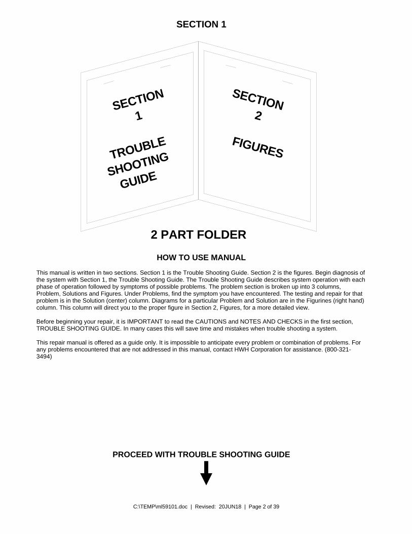
HOW TO USE MANUAL This manual is written in two sections. Section 1 is the Trouble Shooting Guide. Section 2 is the figures. Begin diagnosis of the system with Section 1, the Trouble Shooting Guide. The Trouble Shooting Guide describes system operation with each phase of operation followed by symptoms of possible problems. The problem section is broken up into 3 columns, Problem, Solutions and Figures. Under Problems, find the symptom you have encountered. The testing and repair for that problem is in the Solution (center) column. Diagrams for a particular Problem and Solution are in the Figurines (right hand) column. This column will direct you to the proper figure in Section 2, Figures, for a more detailed view. Before beginning your repair, it is IMPORTANT to read the CAUTIONS and NOTES AND CHECKS in the first section, TROUBLE SHOOTING GUIDE. In many cases this will save time and mistakes when trouble shooting a system. This repair manual is offered as a guide only. It is impossible to anticipate every problem or combination of problems. For any problems encountered that are not addressed in this manual, contact HWH Corporation for assistance. (800-321-3494)
PROCEED WITH TROUBLE SHOOTING GUIDE

C:\TEMP\ml59101.doc | Revised: 20JUN18 | Page 3 of 39
TROUBLE SHOOTING
CAUTIONS!
BLOCK FRAME AND TIRES SECURELY BEFORE CRAWLING UNDER VEHICLE. DO NOT USE AIR SUSPENSION TO SUPPORT VEHICLE WHILE UNDER VEHICLE OR CHANGING TIRES. VEHICLE MAY DROP AND OR MOVE FORWARD OR BACKWARD WITHOUT WARNING CAUSING INJURY OR DEATH. DO NOT EXCEED 5 MPH OR TRAVEL LONG DISTANCES WHEN THE SUSPENSION IS NOT AT THE PROPER RIDE HEIGHT. SAFETY GLASSES ARE TO BE WORN TO PROTECT EYES FROM DIRT, METAL CHIPS, OIL LEAKS, ETC. FOLLOW ALL OTHER SHOP SAFETY PRACTICES.
NOTES AND CHECKS
Read and check before proceeding with Trouble Shooting Steps.
NOTE: HWH CORPORATION ASSUMES NO LIABILITY FOR DAMAGES OR INJURIES RESULTING FROM THE INSTALLATION OR REPAIR OF THIS PRODUCT.
1. The trouble shooting guide must be followed in order. Problems checked for in one step are assumed correct and not checked again in following steps. 2. Batteries should be in good condition and fully charged. Low voltage can cause erratic operation. Important: Not all vehicle air suspensions are plumbed the same. Consult the vehicle manufacturer for specific plumbing diagrams. Also, not all vehicles employ the speed switch to latch the “DUMP” or “RAISE” buttons in. These systems will have momentary “DUMP: and “RAISE” buttons.
This manual is intended for use by experienced mechanics with knowledge of air suspension and automotive electrical systems. People with little or no experience with HWH leveling should contact HWH technical service (800-321-3494) before beginning. Special attention should be given to all cautions, wiring, and air diagrams. Suggested tools for trouble shooting the HWH leveling systems: JUMPER WIRES(UP TO 10 GAUGE) MULTI-METER 12 VOLT TEST LIGHT
PROCEED WITH THE TROUBLE SHOOTING STEPS ON THE FOLLOWING PAGE.

C:\TEMP\ml59101.doc | Revised: 20JUN18 | Page 4 of 39
CONTROL IDENTIFICATION
"EMERGENCY STOP" BUTTON
"EXCESS SLOPE"
"NOT IN PARK"
RAISE RIGHT SIDE BUTTON
LOWER RIGHT SIDE BUTTON
LEVELING LIGHTS(4 - Yellow)
WARNING LIGHTS(4 - Red)
RAISE REAR BUTTON
LOWER REAR BUTTON
"AIR" (ON) BUTTON
DUMP LIGHT
"TRAVEL MODE" BUTTON
"TRAVEL MODE"
LEVELING SYSTEM
"DUMP" BUTTON
RAISE LEFT SIDEBUTTON
LOWER LEFT SIDEBUTTON
RAISE FRONT BUTTON
LOWER FRONT BUTTON
LIGHT
LIGHT
CAUTION!
HWH COMPUTERIZED LEVELING
UNDERSTAND OPERATOR'S MANUAL BEFORE USING. BLOCK FRAME AND TIRESSECURELY BEFORE REMOVING TIRES OR CRAWLING UNDER VEHICLE.
NOT INPARK /BRAKE
DUMP
RAISE
EMERGENCYSTOP
AIR
TRAVEL
TRAVEL
EXCESSSLOPE
RAISE LIGHT
"RAISE" BUTTON
"TRAVEL MODE" BUTTON
LIGHT (Red)
HARD RESET SWITCH(SEE HWH LIGHTED RESET SWITCH)
MASTER WARNING LIGHT
ACTIVE LIGHT
LIGHT (Green)
MODE
MODE
CONTROL FUNCTIONS
CONTROL BUTTONS INDICATOR LIGHTS “AIR” BUTTON: This is the system active and automatic operation button. It woks if the ignition is in the “ON” position. “EMERGENCY STOP” BUTTON: This button turns the system OFF but does NOT control power to the “DUMP” or “RAISE” buttons. Pushing this button will NOT put the system in the TRAVEL mode. “TRAVEL MODE” BUTTON: This button will put the Leveling system in the TRAVEL mode. The ignition must be “ON” for the vehicle to return to proper ride height for traveling. “DUMP” BUTTON: This button will lower the whole coach by dumping air from the suspension system. “RAISE” BUTTON: This button will raise the whole coach by adding air to the suspension system. IMPORTANT: Read “DUMP AND RAISE FUNCTIONS” before using the “DUMP” and “RAISE” buttons. UP ARROWS (RAISE BUTTONS): These momentary buttons are used for manually operating the air leveling systems. Sides or ends of the vehicle will raise while these buttons are pushed. DOWN BUTTONS (LOWER BUTTONS): These momentary buttons are used for manually operating the air leveling systems. Sides or ends of the vehicle will lower while these buttons are pushed.
LEVEL SYSTEM ACTIVE LIGHT: Flashes during automatic leveling and sleep mode. DUMP LIGHT: Flashes when “DUMP” button is pushed. RAISE LIGHT: Flashes when “RAISE” button is pushed. “EXCESS SLOPE” LIGHT: ON if the leveling system can NOT level the coach. “TRAVEL MODE” BUTTON LIGHT (RED): Light flashes for 3 seconds after the “TRAVEL MODE” button is pushed. TRAVEL MODE LIGHT (GREEN): ON if the ignition is in the “ON” position, the system is not being used, and there is sufficient air pressure in the suspension. WARNING LIGHTS: Function with the ignition in the “ON” position. ON when the LEVELING SYSTEM ACTIVE LIGHT flashing. LEVELING LIGHTS: One or two yellow lights can be on indicating the side, end or corner of the coach is low. “NOT IN PARK/BRAKE” LIGHT: ON while the “AIR” button is being pushed if the Park Brake is NOT set. The light will go out when the “AIR” button is released. MASTER WARNING LIGHT: ON any time the “TRAVEL” light is not ON, if the ignition is in the ON position.

C:\TEMP\ml59101.doc | Revised: 20JUN18 | Page 5 of 39
PART 1 – 700 SERIES SYSTEM OPERATION
This section is a description of the touch panel and how the system works, automatically and manually along with a description of how the “DUMP” and “RAISE” buttons work. If you have a good working knowledge of the system, skip ahead to the diagnostics. If you are not familiar with the system, it would be a good idea to review this section. The 700 series air leveling system is a computer controlled BI-AXIS push button system. The system has one touch automatic operation or can be controlled manually. The system will always raise or lower two corners of the vehicle at the same time, in automatic or manual leveling. The buttons and lights of the touch panel are briefly described on the previous page. The ignition must be in the “ON” or “ACC” position for the “AIR”, “DUMP”, “RAISE” or the manual UP and DOWN arrow buttons to function. Pushing the “AIR” button one time starts the automatic leveling sequence. The “TRAVEL MODE” button will take the system out of automatic leveling, SLEEP mode, a DUMP procedure, or a RAISE procedure and return the system to the TRAVEL mode. The vehicle will return to ride height if the ignition is on and there is adequate air supply. The “CANCEL” button will stop the automatic leveling process, SLEEP mode, a DUMP procedure or a RAISE procedure but WILL NOT return the system to the TRAVEL mode. The vehicle will not return to ride height. The “DUMP” button will exhaust air from all of the air bags to lower the vehicle and the “RAISE” button will add air to all of the air bags to raise the vehicle. These two buttons will function if the park brake is not set. They will be explained in greater detail later. The UP and DOWN arrow buttons on the right side of the panel are for manual control. The manual UP and DOWN arrow buttons will function anytime the ignition is in the “ON” or “ACC” position as long as an automatic leveling process has not been initiated or the system is in the SLEEP MODE. Pushing an UP arrow puts air in the air bags, raising the vehicle and a DOWN arrow button will exhaust air from the air bags, lowering the vehicle. Pushing an UP or DOWN arrow button will always control two corners of the vehicle both front, both rear, the right front and right rear and the left front and left rear air bags. The blue LEVELING SYSTEM ACTIVE light above the air button will flash slowly if an automatic leveling process is in progress and flash rapidly when in the SLEEP mode. When in the SLEEP mode, this light will continue to flash rapidly even when the ignition key is off. This light will only flash for auto level and the sleep mode and should never be on steady. The blue light above the “TRAVEL MODE” button will flash a few times after the “TRAVEL MODE” button is pushed. It will not continue to flash nor should this light ever be on steady. The four red WARNING lights at the corners of the manual UP and DOWN arrow buttons will be on steady anytime the LEVELING SYSTEM ACTIVE light is flashing or if the “DUMP” or “RAISE” buttons are being used if the ignition is in the “ON” or “ACC” position. The four yellow lights between the WARNING lights are the level indicator lights. A lit yellow LEVEL light indicates that that side or end of the vehicle is low. One or two LEVEL lights can be on but never opposing lights. The yellow LEVEL lights can be on if the ignition is on and the park brake is set. The “NOT IN PARK/BRAKE” light will come on if the “AIR” button or the manual UP or DOWN arrow buttons are being pushed with the ignition on. The system will not function in auto or manual if the park brake is not set. The “NOT IN PARK/BRAKE” light will also come on if the “DUMP” or “RAISE” buttons are being pushed but those buttons will function with or without the park brake set. The “EXCESS SLOPE” light will be addressed when we discuss an EXCESS SLOPE situation during automatic leveling The green “TRAVEL MODE” light will be on anytime the ignition is on if the LEVELING SYSTEM ACTIVE light is not flashing or the RAISE or DUMP lights are not on. The front air manifold will have a 20 psi pressure switch to monitor the air bag pressure for each side. The rear air manifold will have a 20 psi pressure switch to monitor the air bag pressure for each side and an 85 psi pressure switch that monitors the system air pressure. If the ignition is on, the park brake is off and a pressure switch is on, the TRAVEL MODE light will not be on. Note: Some vehicles may have two air bags for each corner plus one air bag for each side of the tag axle if so equipped. For ease of discussion we will refer to the “left front air bag”, “right front air bag”, “right rear air bag” and “left rear air bag”. If the vehicle has an arrangement of two air bags for each side of an axle, these bags will simply be teed together, acting as one. Tag axle information will be addressed separately when necessary. For most systems, the tag axle will mirror what the drive axle is doing for leveling purposes.

C:\TEMP\ml59101.doc | Revised: 20JUN18 | Page 6 of 39
AUTOMATIC OPERATION It is best to leave the engine running for the automatic leveling procedure. The ignition must be in the “ON” or “ACC” position to initiate automatic leveling. The park brake must be set. If not set, the “NOT IN PARK/BRAKE” light will come on while pushing the “AIR” button and the system will not function. One or two yellow level lights may be on at this time. Pushing the “AIR” button one time will initiate the automatic leveling sequence. The LEVELING SYSTEM ACTIVE light above the “AIR” button will start to flash. The system will first exhaust the air from all of the air bags, even if no yellow level lights are lit. If all level lights are off after the dump cycle, the system will go immediately into the SLEEP mode. When the last air bag pressure switch is made, the processor will determine the high corner of the vehicle. The lower valve load for that corner will remain on during the complete leveling process and remain on until level is achieved with all yellow level lights off or until an EXCESS SLOPE situation is encountered. The rest of the lower valve loads will be turned off. At this time, the auxiliary air compressor load will be turned on and like the high corner lower valve, will stay on during the complete leveling process. At this point, all leveling will be achieved by raising a side or end of the vehicle. The processor will always level side to side if necessary before leveling the vehicle front to rear. If a front and side level light is on, the processor will turn the side raise loads on until the side light turns off. After a two second pause, the processor will turn the front raise loads on until the front level light is off. If the side level light comes back on, the system will ignore that light until the front light goes out then the processor will turn the side raise load back on until the side level light goes out. When all four level lights are out, the vehicle is level and the processor will go into the SLEEP mode. The LEVELING SYSTEM ACTIVE light will now flash rapidly. This will continue until the “CANCEL” button or the “TRAVEL MODE” button is pushed. Releasing the park brake with the ignition on or off will cancel the SLEEP mode and turn the LEVELING SYSTEM ACTIVE light off. If only a front or rear level light is on when automatic leveling is initiated, after the initial lowering of the vehicle, the system will first try to level the vehicle from front to rear. If a side light comes on during the leveling procedure, when the front or rear light goes out, the system will raise the side for the leveling light that is lit. FLICKERING YELLOW LEVEL LIGHTS. When an active level light flickers during the automatic leveling procedure, the system will pause until that light comes on or turns off for two seconds then continue with the leveling process as needed. Here are a couple examples. Scenario 1: The front and left side level lights are on. The left side raise loads are on, lifting the left side. If the front level light flickers, the leveling process is not interrupted. The left side continues to rise. If the left side light flickers, the process stops, turning the raise loads off, until the light comes on solid or turns off for two seconds. If the light comes on solid, the raise loads for the left side turn back on and will continue to raise the left side until the light goes out and remains out. If the light flickers and then stays off, the processor will move to the front level light turning the raise loads for the front on until the front yellow light goes out. Scenario 2: The front and left side level lights are on. The left side raise loads are on. The left side level light goes out. The processor turns the front raise loads on and starts lifting the front. The left side level light comes back on. The processor will ignore that light until the front level light goes out. The front level light flickers. If the front light turns back on solid, the processor continues to raise the front until that light remains off. If the light goes out for 2 seconds, the processor will go back to the left side level light, turn the left side raise loads on and keep them on until the left side level light goes out. If the front light comes back on, the processor would go back and try to turn the front level light out. SLEEP MODE SLEEP mode happens only if automatic leveling has been used. The processor will put the system in the SLEEP mode when all the yellow level lights are out in the automatic leveling process. The LEVELING SYSTEM ACTIVE light will start flashing rapidly. The ignition can be turned off and the system will stay in the SLEEP mode. Thirty (30) minutes after the SLEEP mode is initiated, the processor will wake up and monitor the yellow level lights. If any yellow level light comes on solid, the processor will initiate a leveling procedure. The LEVELING SYSTEM ACTIVE light will flash slowly. Depending on lit level lights and air bag pressure switch conditions, the processor may do a lower procedure before starting the normal level by raising the vehicle procedure. Once leveling is achieved, the processor will return the system to the SLEEP mode for thirty (30) minutes. The LEVELING SYSTEM ACTIVE light will again flash rapidly. EXCESS SLOPE EXCESS SLOPE is a timed sequence. Very simply, approximately fifteen (15) minutes after the “AIR” button has been pushed, if any yellow level light is on, the EXCESS SLOPE light will come on and all loads will turn off. The EXCESS SLOPE light will remain on until the park brake is released or the “TRAVEL MODE” button has been pushed. The ignition can be off or on. The manual UP and DOWN arrow buttons will function with the EXCESS SLOPE light on, if the ignition is in “ON” or “ACC” position. The “AIR”, “DUMP” AND “RAISE” buttons will not function if the EXCESS SLOPE light is on.

C:\TEMP\ml59101.doc | Revised: 20JUN18 | Page 7 of 39
MANUAL OPERATION The UP and DOWN arrow button on the right side of the touch panel allow manual control of the air bags. The ignition must be in the “ON” or “ACC” position and the park brake must be set for the UP and DOWN arrows to function. There are four sets of buttons, front, left side, right side and rear. The UP arrow buttons will open the raise valves to allow are into the air bags, raising the vehicle. The DOWN arrow buttons will open the lower valves to exhaust air from the air bags, lowering the vehicle. These buttons will always operate two corners of the vehicle at a time for Bi-Axis leveling, both front air bags, both rear air bags, the left front and left rear air bags or the right front and right rear air bags. It is not recommended to push more than one UP or DOWN arrow at a time. You can lower the vehicle first like the automatic leveling sequence does or you can level the vehicle by first lowering the side and/or end of the vehicle opposite of any lit yellow level light. I. E. The left side level light is on. Push and hold the DOWN arrow button for the right side. If lowering the right side does not turn the left side level light out, push and hold the left side UP arrow to raise the left side of the vehicle. It is recommended to level the vehicle side to side first, if needed, then front to rear. The UP and DOWN arrow buttons will not function if the LEVELING SYSTEM ACTIVE light is flashing. NOTE: There is no EXCESS SLOPE or SLEEP mode in manual leveling. If the “AIR” button is pushed after manually leveling the vehicle, even if all yellow level lights are out, the auto level sequence will start from the beginning including first dumping all air from the air bags. “DUMP” AND “RAISE” BUTTONS The DUMP button will exhaust air from all of the suspension air bags to lower the whole vehicle. The RAISE button will add air to all of the suspension air bags to RAISE vehicle. The ignition has to be in the “ON” or “ACC” position for the DUMP and RAISE buttons to function but the park brake does NOT have to be set. The system has a wire that connects to the transmission speed switch. When below the speed setting of the switch, the DUMP and RAISE buttons will latch in and lower or raise the vehicle to the minimum (lower) or maximum (raise) height allowed by the suspension and air bags. If the system is not connected to the speed switch, the buttons become momentary and will stop lowering or raising the vehicle when released. If the park brake is off, the suspension will return to the normal ride height. IMPORTANT: The DUMP and RAISE buttons are a feature that allow you to raise or lower the vehicle while moving at a very slow speed to clear an obstacle such as a curb or branch. The vehicle should not travel any significant distance without being at the proper ride height.
C:\TEMP\ml59101.doc | Revised: 20JUN18 | Page 8 of 39
PART 2 – TROUBLE SHOOTING
TROUBLE SHOOTING BASICS (Please read before continuing) When trouble shooting the 700 series air leveling system, it is best to run the system in the manual mode to check individual functions before operating the system in the automatic mode. If the system won’t work in manual, it won’t work in automatic. It is important to remember the HWH works with the vehicle suspension to achieve leveling or ride height. Each HWH air manifold has 6 valves, a right and left travel valve, a right and a left lower valve and a right and a left raise valve. There is a manifold for the front axle and the rear axle. A travel valve allows air to pass through the manifold from a Height Control Valve to the air bag so the Height Control Valves can control the suspension. A lower valve allows air to exhaust from the air bag to lower the vehicle. A raise valve allows air to flow into the air bag to raise the vehicle. How high of low a vehicle can go is a function of available air pressure and the limitations of the suspension equipment, air bags, shocks, etc. Start the engine and push the “TRAVEL MODE” button. Let air pressure build and allow the vehicle to return to travel height. This will make the following procedures easier to perform. If the vehicle will not return to travel height, see Step 2. When trouble shooting, it is important to pay attention to the air bags instead of just watching the vehicle. Because air is highly compressible, watching the vehicle move up or down can give you a false impression of what is really happening. When checking to see if a lower valve is working, wait until air stops exhausting then check that the air bags corresponding to the DOWN arrow button being pushed are totally empty or flat. When checking to see if a raise or travel valve is working, make sure there is adequate air supply and check the air bags corresponding to the UP arrow being pushed or if working on the TRAVEL MODE, all the air bags should have re-inflated. This is the most reliable way to make sure the system is functioning properly. It is best to check all four sets of UP and DOWN arrows. First use the DOWN arrow and check the appropriate bags are empty then push the corresponding UP arrow and make sure the bags have re-inflated. Each air manifold is equipped with two 20 psi pressure switches, one for each side. These are normally closed switches. The contacts will open at approximately 20 psi. These switches are used as a warning device when traveling and also to establish the high corner of the vehicle for automatic leveling. If the ignition is on and the park brake is off, one (1) minute after an air bag pressure switch comes on, the green TRAVEL MODE light will go out and the master warning light will come on. The drive axle manifold also has an 85 psi switch that monitors vehicle air system pressure. This switch is only used as a warning device. If the ignition is on and the park brake is released the TRAVEL MODE light will turn off and the master warning light will turn on as soon as the switch comes on. The air manifold MIOMs are equipped with LEDs that can assist with diagnostics. Refer to electrical diagrams for LED information. Lit LEDs indicate there is an output but LOW VOLTAGE must always be considered and addressed. When asked to check for +12 power or voltage and ground, ignition voltages should be above 10.5 volts and output voltages should be above 10.0 volts. Equipment will work at a lower voltage but levels below 10.0 – 10.5 volts may indicate a connection, corrosion or battery issue. ALL VOLTAGES SHOULD BE CHECKED UNDER LOAD.
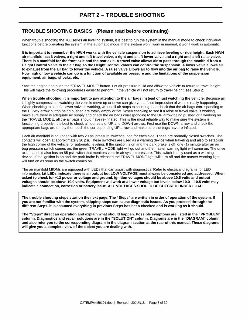
The trouble shooting steps start on the next page. The “Steps” are written in order of operation of the system. If you are not familiar with the system, skipping steps can cause diagnostic issues. As you proceed through the different Steps, it is assumed everything in previous Steps has been checked and is working as it should. The “Steps” direct an operation and explain what should happen. Possible symptoms are listed in the “PROBLEM” column. Diagnostics and repair solutions are in the “SOLUTION” column. Diagrams are in the “DIAGRAM” column and also refer you to the corresponding diagram in the diagram section at the rear of this manual. These diagrams will give you a complete view of the object you are dealing with.

C:\TEMP\ml59101.doc | Revised: 20JUN18 | Page 9 of 39
TROUBLE SHOOTING
Step 1. Check that the green TRAVEL MODE light is not on. Make sure the park brake is set. Turn the ignition to the “ON” or “ACC” position. The TRAVEL MODE light should come on. +12 power for the touch panel and MIOMs is routed to the front MIOM through the system latch in relay assembly.
PROBLEM SOLUTION DIAGRAMS Step 1a. The green TRAVEL MODE light is on with the ignition off.
The issue will be at the front air module MIOM. There is power on the red 6120 wire for pin A1 or the red 6102 wire for pin D1 of the front MIOM main connector. There should be no power on these wires with the ignition off. The 6120 wire is ignition power. The 6102 wire is battery power. If there is power on the 6120 wire there should also be power on the 6102 wire. If there is no power on the 6120 wire but there is power on the 6102 wire, the CR1 or CR2 Bosch relay is stuck on and should be replaced.
8 7 6 5 4 3 2 1ABCD
FRONT VIEW OF I/O MODULE
CONNECTOR
REFER TO MP84.3180
LINK LIGHT
PIN 1
HWH COMPUTERIZED LEVELING
WARNING!UNDERSTAND OPERATOR'S MANUAL BEFORE USING. BLOCK FRAME AND TIRES
SECURELY BEFORE REMOVING TIRES OR CRAWLING UNDER VEHICLE.
EMERGENCYSTOP
MODETRAVEL
LEVEL
MODETRAVEL
RAISE
BRAKEPARK/
SLOPEEXCESS
NOT IN
DUMP
AIR
CN1
REFER TO MP84.6195
LINK LIGHT
REFER TO MP84.3180
SYSTEM LATCHIN RELAYS
SEE MP84.3200
AB
61206101
REFER TO MP84.3060
Step 1b. The green TRAVEL MODE light is off. The ignition is on. The park brake is set.
If a yellow level light is on, replace the touch panel. If a level light is not lit, push the “RAISE” or “DUMP” button. If the light above the button comes on, replace the touch panel. If the light does not come on, there is a system power or communication problem between the MIOMs and the touch panel. There is a link light on the back of the touch panel and one on each air manifold MIOM. These lights should be flashing with the ignition on. CHECK THAT ALL LINK LIGHTS ARE FLASHING. ALL LINK LIGHTS ARE FLASHING – Check for +12 power on the red 6120 wire (pin A1) at the front MIOM. If +12 power is present, replace the MIOM. If +12 power is not present, there is an issue with the 6120 wire between the front MIOM and the latch in relay assembly. Check the wire and plug connections. Fix as necessary. SOME LINK LIGHTS ARE OFF OR ON STEADY. There is most likely a communication issue. There may also be a power issue for a MIOM or the touch panel. Check for +12 power between wires 6122 (red) and 6230 white at the MIOMs and touch panel. If +12 power is not present, repair the harness wires as necessary. If +12 power is present at all components, unplug the main connector from the front and rear MIOMs and the 5 pin MTA connector from the touch panel. At the touch panel, check resistance between pins 1 and 2, the yellow and green wires, of the MTA connector. There should be between 55 and 65 Ohms of resistance. If the resistance is not correct, there is an issue with the harness There is a 120 OHM resistor between the yellow and green wires in the harness near the touch panel and the rear MIOM. If you measure approximately 120ohms, one of the resistors may be bad or possibly a bad spot in one of the wires. If resistance measures OK, make sure the yellow and green wires are properly seated in the connectors. Make sure the yellow and green wires are in the proper location at all connectors including the front MIOM. At the MIOMs, the yellow wire should be on pin A2. The green wire should be on pin B2. At the touch panel, the yellow wire should be on pin 1 and the green wire should be on pin 2. If resistance is OK and the wires are seated properly in the correct locations, the issue is the touch panel or one of the MIOMs. There is no good way to test these components. Try the touch panel first but you may want to order all three parts and make arrangements to return the unused parts.
8 7 6 5 4 3 2 1ABCD
FRONT VIEW OF I/O MODULE
CONNECTOR
REFER TO MP84.3180

C:\TEMP\ml59101.doc | Revised: 20JUN18 | Page 10 of 39
TROUBLE SHOOTING
PROBLEM SOLUTION DIAGRAMS
REFER TO MP84.3181
Step 1b. Cont. ALL LINK LIGHTS ARE OFF – Make sure there is a good ground on the MIOM ground stud. Fix if necessary. With the ignition on, check at the main connector of the front MIOM for +12 power between the red 6102 wire (pin D1) and the white 6230 wire (pin D3). There is +12 power between the red 6102 wire (Pin D1) and the white 6230 wire (pin D3) in the front MIOM main connector. Check for power between the red 6122 wire (pin B1) and the white 6230 wire. If power is present, refer to “SOME LINK LIGHTS ARE OFF OR ON STEADY” on the preceding page. If power is not present, replace the MIOM. There is no +12 power between the red 6102 wire (Pin D1) and the white 6230 wire (pin D3) in the front MIOM main connector. Check for power between the 6230 ground wire and the red 6120 wire in pin A1. There is +12 power on the red 6120 wire at the front MIOM main connector, pin A1 but no power on the red 6102 wire, pin D1. The issue is the CR1 relay in the latch in assembly or the battery supply wire, 6102. Check for ground on the white 6235 wire at terminal 86 of CR1 and check for +12 on the red 6120 wire at terminal 85 of CR1. If ground is not present, check the 6235 wire and its connections to the 2-pin MIOM Packard connector for the latch in assembly. Fix as necessary. If the wire and connections are good, replace the MIOM. If +12 power is not present at terminal 85, the issue is with the 6120 wire at the latch in assembly. Fix as necessary. If there is power and ground for the CR1 relay coil, check for +12 power on the red 6101 wire for terminal 30 of CR1. If power is present at terminal 30 of CR1, check for power on the red 6102 wire for terminal 87 of CR1. If power is not present, replace the CR1 relay. If power is present at terminal 87, there is an issue with the red 6102 wire, pin connections or connections between the latch in assembly and the front MIOM. Fix as necessary. If power is not present at terminal 30 of CR1, the issue is the red 6101 wire from the reset switch to CR1, terminal 30, the reset switch, the red 6100 wire from the reset switch to its source or the fuse for the 6100 wire is blown. If the fuse is ok, repair the wire, switch or connections as necessary.
62356101
6102
6101 6235
6102 7500
62356120
61027500
6120
BA
CR1 CR2
87 85
8630
8587
30 86
REFER TO MP84.3200

C:\TEMP\ml59101.doc | Revised: 20JUN18 | Page 11 of 39
TROUBLE SHOOTING
PROBLEM SOLUTION DIAGRAMS
6101
6102
CR2
BA
RESET SWITCH (NC)
61006101
6101 6101 6100
FUSE5 AMP
TO +12 BATTERY
87 85
8630
REFER TO MP84.3200
Step 1b. Cont. The five amp fuse for +12 battery power to the latch in relay assembly is blown. Turn the ignition off. Replace the fuse. If the fuse blows, the problem is on the red 6100 or red 6101 wire between the latch in relay assembly and the fuse. If the fuse does not blow, unplug the front MIOM. Turn the ignition key on. If the fuse blows, the issue is on the red 6102 between the relay assembly and the front MIOM. If the fuse does not blow, turn the ignition off. Unplug the rear MIOM, both touch panel plugs and the level sensing unit. Leave the front MIOM unplugged. There should be no continuity between the red wires for pins B1, C1, D1 of the front MIOM main connector and any white wires in the main harness or to any frame ground. Check for continuity and fix as necessary. If the harness wires are ok, turn the ignition on and plug the front MIOM back in. If the fuse blows, replace the MIOM. If the fuse does not blow, plug in the rear MIOM. If the fuse blows, replace the rear MIOM. If the fuse does not blow, plug in the 5-pin MTA touch panel connector. If the fuse blows, replace the touch panel. If the fuse does not blow, plug the 6-pin UML touch panel connector back in. If the fuse blows, there is a problem with the red 6110 wire in the warning light pigtail. Repair as necessary. If the fuse does not blow, plug the level sensing unit back in. If the fuse blows, replace the sensing unit. If the fuse does not blow, continue with system diagnostics as needed. TRUNK
HARNESS
HWH MAIN
HWH MAIN
HARNESSTRUNK
RE
SIS
TO
RT
ER
MIN
AT
ING
DO
NO
T CU
TT
ER
MIN
AT
ING
RE
SIS
TOR
DO
NO
T C
UT
TOUCH PANELSEE MP84.6195
MASTERWARNING
LIGHT7699
6110
LATCHSYSTEM
LEVEL SENSING UNITSEE MP84.3433
AB
FRONT AIR MANIFOLDI/O MODULE
SEE MP84.3180
SEE MP84.3190I/O MODULE
REAR AIR MANIFOLD
HWH COMPUTERIZED LEVELING
WARNING!UNDERSTAND OPERATOR'S MANUAL BEFORE USING. BLOCK FRAME AND TIRES
CANCEL
MODETRAVEL
LEVEL
MODETRAVEL
RAISE
BRAKEPARK/
SLOPEEXCESS
NOT IN
DUMP
AIR
SECURELY BEFORE REMOVING TIRES OR CRAWLING UNDER VEHICLE.
REFER TO MP84.3060
WARNING: DO NOT CRAWL UNDER THE VEHICLE UNLESS THE VEHICLE IS SECURELY SUPPORTED AND CANNOT DROP WHEN AIR IS EXHAUSTED FROM THE SUSPENSION AIR BAGS. MAKE SURE THERE IS AMPLE ROOM UNDER THE VEHICLE TO AVOID MOVING SUSPENSION PARTS WHEN AIR IS EXHAUSTED OR ADDED TO THE SUSPENSION AIR BAGS. SERIOUS INJURY OR DEATH CAN OCCUR
Step 2. Start the vehicle engine. Make sure there is at least 100 psi in the vehicle air tanks. Push the “TRAVEL MODE” button. The blue TRAVEL MODE button light should flash a few times. The vehicle should come to ride height. Check that all the suspension air bags are inflated.
Step 2a. The blue Travel Mode button light does not flash.
Review Part 1b. Make sure there is good +12 power and ground to the MIOMs and touch panel and make sure all link lights are flashing as explained in Step1b. If Step 1b. checks ok, replace the touch panel.
LEFT FRONT TRAVEL
RIGHT FRONT TRAVEL
REFER TO MP84.3180 OR MP84.3190
Step 2b. One or more air bags are not inflated. The blue Travel Mode button light did flash
If there is a Height Control Valve for each side of the axle, the issue could be HWH or the Height control valve. WARNING: MAKE SURE THE FRAME OF THE VEHICLE IS PROPERLY SUPPORTED BEFORE CRAWLING UNDER THE VEHICLE. SEVERE INJURY OR DEATH CAN OCCUR. With the ignition on check that the travel valve LED for the bag(s) not inflating is lit. There are two travel valves and travel LEDs on each manifold. If the travel valve LED is lit, turn the “BY-PASS VALVE” T-handle on the side of the manifold counterclockwise several turns. If the bag inflates, the travel valve for that bag is most likely the issue.
L EXHAUSTRI
VALVE
BY-PASS
[ HCV ]
BAG
AXLE AIR IN
VALVE
BY-PASS
REFER TO MP84.3181

C:\TEMP\ml59101.doc | Revised: 20JUN18 | Page 12 of 39
TROUBLE SHOOTING
PROBLEM SOLUTION DIAGRAMS Step 2b. Cont. Check for +12 volts between the two pins of the MIOM
Packard connector. If power is present, replace the valve. If power is not present, the issue is the connection or MIOM. If the connection of the wires in the connector is ok, replace the MIOM. If the bag does not inflate with the manifold T-handle opened, the issue is the Height control valve or possibly something in the system plumbing. Make sure the T-handle is closed snugly after completing the test. NOTE: If the T-handle does not turn fairly easy, do not try to force it, you can damage the manifold. Go ahead with the voltage test at the valve and if voltage is ok, remove the travel valve. If air comes out of the manifold, replace the valve. If no air comes out, the issue is the Height Control Valve or the plumbing. If the travel valve LED is not lit, turn the ignition off, unplug the valve, the main MIOM connector and the 2 pin MIOM plug for high current and ground. Wait about 10 seconds, then plug the main connector and the 2 pin connector back in. Do not plug the valve back in. Turn the ignition on. If the travel valve LED now comes on, replace that travel valve. If the travel valve LED still does not come on, replace the MIOM.
W2700TRAVEL
RS
BA
AB
AB
BA
BA
AB
AB
TRAVELW1700
LS
RED (6100)
WHITE (6234)
62452700
17006246
WHITE
BLACK
MAINCONNECTOR
REFER TO MP84.3181
Step 3. With the ignition in the “ON” or “ACC” position and the park brake set, push the “DUMP” button to exhaust the air from all the air bags. The DUMP light should start flashing and continue flashing. When air has stopped exhausting, push the “CANCEL” button. The DUMP light should stop flashing. Check that all the air bags are totally deflated.
Step 3a. The DUMP light will not come on and flash.
Whenever the ignition is in the “ON” or “ACC” position, there should be +12 volts on the black 9900 wire going to the main connector, pin C6, of the front MIOM. This is the speed switch wire. If +12 is not present, there is an issue with the transmission output, the 9900 wire, its connections to the HWH MIOM or the transmission speed switch. If +12 is present, replace the touch panel. NOTE: +12 volts will not be present when the vehicle is traveling above the speed the speed switch is programmed for.
8 7 6 5 4 3 2 1ABCD
FRONT VIEW OF I/O MODULE
CONNECTOR
REFER TO MP84.3180
EXHAUST
AXLE AIR IN[ HCV ]
LEFT
BY-PASSVALVE
RIGHT
AIRIN
BAG
R
BAGPSW
BY-PASSVALVEBAG
CHECK VALVES
AIR SUPPLY
AIR BAGSLINE TO
CONTROLHEIGHTLINE FROM
VALVES
3.400"
FRONT AIR MANIFOLDREAR VIEW
SWITCHES (2)PRESSURE
PRESSURE REGULATOR
REFER TO MP74.2670A
Step 3b. One or more air bags do not deflate. The other air bags do deflate.
First, make sure the exhaust ports for the bags that will not exhaust air are not plugged with dirt or debris. Clean if necessary. Use caution as the air will start to dump after cleaning the ports if the DUMP light is still flashing. With the DUMP button light flashing, check the LED for any lower valve that controls an air bag that did not exhaust air. If the LED is lit, check for +12 volts between the two pins of the MIOM connector. If +12 volts is present, replace the valve. If +12 is not present the issue is the wires or their connections in the plug. Fix if possible or replace the MIOM. If the LED is not lit, turn the engine off, unplug the valve, the main MIOM connector and the 2 pin MIOM plug for high current and ground. Wait about 10 seconds, then plug the main connector and the 2 pin connector back in. Do not plug the valve back in. Turn the ignition on. If the lower valve LED now comes on, replace that lower valve. If the lower valve LED still does not come on, replace the MIOM.
*
RIGHT FRONT TRAVELRIGHT FRONT LOWERRIGHT FRONT RAISEAIR COMPRESSOR
LINK LIGHT
LEFT FRONT LOWERLEFT FRONT TRAVEL
SYSTEM LATCHLEFTFRONTRAISE
REFER TO MP84.3180
C:\TEMP\ml59101.doc | Revised: 20JUN18 | Page 13 of 39
TROUBLE SHOOTING
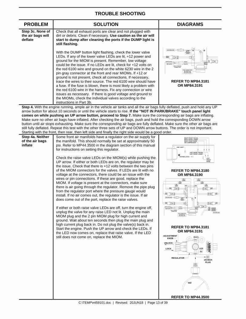
PROBLEM SOLUTION DIAGRAMS Step 3c. None of the air bags will deflate
Check that all exhaust ports are clear and not plugged with dirt or debris. Clean if necessary. Use caution as the air will start to dump after cleaning the ports if the DUMP light is still flashing. With the DUMP button light flashing, check the lower valve LEDs. If any of the lower valve LEDs are lit, +12 power and ground for the MIOM is present. Remember, low voltage could be the issue. If no LEDs are lit, check for +12 volts on the red 6100 wire and ground on the white 6230 wire in the 2 pin gray connector at the front and rear MIOMs. If +12 or ground is not present, check all connections. If necessary, trace the wires to their source. The red 6100 wire should have a fuse. If the fuse is blown, there is most likely a problem with the red 6100 wire in the harness. Fix any connection or wire issues as necessary. If there is good voltage and ground to the MIOMs, check the individual valves according to the instructions in Part 3b.
W7500RELAYLATCH
AB
BA
SEE MP84.6085
SEE MP84.3180INFORMATION
FOR CONNECTION
RED (6100)
WHITE (6234)
62442500
WHITE
BLACK
HIGH CURRENTCONNECTOR
CONTROLW9700
RELAY COMP
REFER TO MP84.3181 OR MP84.3191
Step 4. With the engine running, ample air in the vehicle air tanks and all the air bags fully deflated, push and hold any UP arrow button for about 10 seconds or until the vehicle starts to rise. If the “NOT IN PARK/BRAKE” touch panel light comes on while pushing an UP arrow button, proceed to Step 7. Make sure the corresponding air bags are inflating. Make sure no other air bags have inflated. After checking the air bags, push and hold the corresponding DOWN arrow button until air stops exhausting. Make sure the corresponding air bags are fully deflated. Make sure the other air bags are still fully deflated. Repeat this test with the other three sets of UP and DOWN arrow buttons. The order is not important. Starting with the front, then rear, then left side and finally the right side would be a good order.
*
RIGHT FRONT TRAVELRIGHT FRONT LOWERRIGHT FRONT RAISEAIR COMPRESSOR
LINK LIGHT
LEFT FRONT LOWERLEFT FRONT TRAVEL
SYSTEM LATCHLEFTFRONTRAISE
REFER TO MP84.3180 OR MP84.3190
CONTROLW9700
RELAY COMP
W2700TRAVEL
RAISEW2500
W2600LOWER
RS
RS
RS
W7500RELAYLATCH
BA
AB
AB
BA
BA
AB
AB
TRAVELW1700
LS
W1600LOWER
LS
LSRAISEW1500
SEE MP84.6085
SEE MP84.3200
SEE MP84.3180INFORMATION
FOR CONNECTION
RED (6100)
WHITE (6234) 6235750061026120
62452700
62432600
62442500
17006246
16006241
15006242
WHITE
BLACK
HIGH CURRENTCONNECTOR
REFER TO MP84.3181 OR MP84.3191
Step 4a. Neither of the air bags inflate
Some front air manifolds have a regulator on the air supply for the manifold. This should normally be set at approximately 50 psi. Refer to MP44.3500 in the diagram section of this manual for instructions on setting this regulator. Check the raise valve LEDs on the MIOM(s) while pushing the UP arrow. If either or both LEDs are on, the regulator may be the issue. Check that there is +12 volts between the two pins of the MIOM connectors for the valves. If LEDs are lit with no voltage at the connectors, there could be an issue with the wires or pin connections. If these are good, replace the MIOM. If voltage is present at the connectors, make sure there is air going through the regulator. Remove the pipe plug from the regulator port where the pressure gauge would install. If no air comes out, the regulator is the issue. If air does come out of the port, replace the raise valves. If either or both raise valve LEDs are off, turn the engine off, unplug the valve for any raise LED not lit. Unplug the main MIOM plug and the 2 pin MIOM plug for high current and ground. Wait about ten seconds then plug the main plug and high current plug back in. Do not plug the valve(s) back in. Start the engine. Push the UP arrow and check the LEDs. If the LED now comes on, replace that raise valve. If the LED still does not come on, replace the MIOM.
R200
BAG
AIRIN
1/8 INCHPLUG
REGULATOR
KNOBADJUSTMENT
UNLOCK
LOCK
REFER TO MP44.3500
C:\TEMP\ml59101.doc | Revised: 20JUN18 | Page 14 of 39
TROUBLE SHOOTING
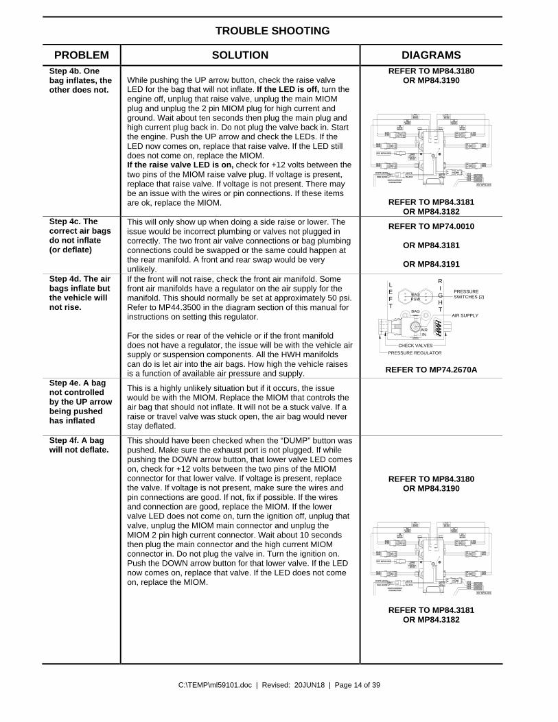
PROBLEM SOLUTION DIAGRAMS Step 4b. One bag inflates, the other does not.
While pushing the UP arrow button, check the raise valve LED for the bag that will not inflate. If the LED is off, turn the engine off, unplug that raise valve, unplug the main MIOM plug and unplug the 2 pin MIOM plug for high current and ground. Wait about ten seconds then plug the main plug and high current plug back in. Do not plug the valve back in. Start the engine. Push the UP arrow and check the LEDs. If the LED now comes on, replace that raise valve. If the LED still does not come on, replace the MIOM. If the raise valve LED is on, check for +12 volts between the two pins of the MIOM raise valve plug. If voltage is present, replace that raise valve. If voltage is not present. There may be an issue with the wires or pin connections. If these items are ok, replace the MIOM.
REFER TO MP84.3180 OR MP84.3190
CONTROLW9700
RELAY COMP
W2700TRAVEL
RAISEW2500
W2600LOWER
RS
RS
RS
W7500RELAYLATCH
BA
AB
AB
BA
BA
AB
AB
TRAVELW1700
LS
W1600LOWER
LS
LSRAISEW1500
SEE MP84.6085
SEE MP84.3200
RED (6100)
WHITE (6234) 6235750061026120
62452700
62432600
62442500
17006246
16006241
15006242
WHITE
BLACK
HIGH CURRENTCONNECTOR
REFER TO MP84.3181
OR MP84.3182 Step 4c. The correct air bags do not inflate (or deflate)
This will only show up when doing a side raise or lower. The issue would be incorrect plumbing or valves not plugged in correctly. The two front air valve connections or bag plumbing connections could be swapped or the same could happen at the rear manifold. A front and rear swap would be very unlikely.
REFER TO MP74.0010
OR MP84.3181
OR MP84.3191
Step 4d. The air bags inflate but the vehicle will not rise.
If the front will not raise, check the front air manifold. Some front air manifolds have a regulator on the air supply for the manifold. This should normally be set at approximately 50 psi. Refer to MP44.3500 in the diagram section of this manual for instructions on setting this regulator. For the sides or rear of the vehicle or if the front manifold does not have a regulator, the issue will be with the vehicle air supply or suspension components. All the HWH manifolds can do is let air into the air bags. How high the vehicle raises is a function of available air pressure and supply.
LEFT
RIGHT
AIRIN
BAG
R
BAGPSW
CHECK VALVES
AIR SUPPLY
SWITCHES (2)PRESSURE
PRESSURE REGULATOR
REFER TO MP74.2670A
Step 4e. A bag not controlled by the UP arrow being pushed has inflated
This is a highly unlikely situation but if it occurs, the issue would be with the MIOM. Replace the MIOM that controls the air bag that should not inflate. It will not be a stuck valve. If a raise or travel valve was stuck open, the air bag would never stay deflated.
Step 4f. A bag will not deflate.
This should have been checked when the “DUMP” button was pushed. Make sure the exhaust port is not plugged. If while pushing the DOWN arrow button, that lower valve LED comes on, check for +12 volts between the two pins of the MIOM connector for that lower valve. If voltage is present, replace the valve. If voltage is not present, make sure the wires and pin connections are good. If not, fix if possible. If the wires and connection are good, replace the MIOM. If the lower valve LED does not come on, turn the ignition off, unplug that valve, unplug the MIOM main connector and unplug the MIOM 2 pin high current connector. Wait about 10 seconds then plug the main connector and the high current MIOM connector in. Do not plug the valve in. Turn the ignition on. Push the DOWN arrow button for that lower valve. If the LED now comes on, replace that valve. If the LED does not come on, replace the MIOM.
REFER TO MP84.3180 OR MP84.3190
CONTROLW9700
RELAY COMP
W2700TRAVEL
RAISEW2500
W2600LOWER
RS
RS
RS
W7500RELAYLATCH
BA
AB
AB
BA
BA
AB
AB
TRAVELW1700
LS
W1600LOWER
LS
LSRAISEW1500
SEE MP84.6085
SEE MP84.3200
RED (6100)
WHITE (6234) 6235750061026120
62452700
62432600
62442500
17006246
16006241
15006242
WHITE
BLACK
HIGH CURRENTCONNECTOR
REFER TO MP84.3181
OR MP84.3182
C:\TEMP\ml59101.doc | Revised: 20JUN18 | Page 15 of 39
TROUBLE SHOOTING
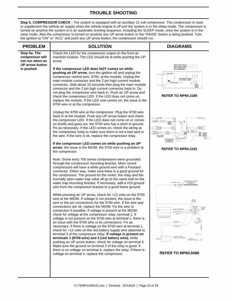
Step 5. COMPRESSOR CHECK - The system is equipped with an auxiliary 12 volt compressor. The compressor is used to supplement the vehicle air supply when the vehicle engine is off and the system is in the sleep mode. The compressor is turned on anytime the system is in an automatic leveling sequence, including the SLEEP mode, once the system is in the raise mode. Also the compressor is turned on anytime any UP arrow button or the “RAISE” button is being pushed. Turn the ignition to “ON” or “ACC” and push any UP arrow button, the compressor should run.
PROBLEM SOLUTION DIAGRAMS
*
RIGHT FRONT TRAVELRIGHT FRONT LOWERRIGHT FRONT RAISEAIR COMPRESSOR
LINK LIGHT
LEFT FRONT LOWERLEFT FRONT TRAVEL
SYSTEM LATCHLEFTFRONTRAISE
REFER TO MP84.3180
CONTROLW9700
RELAY COMP
W7500RELAYLATCH
BA
B
BA
BA
A
SEE MP84.6085
SEE MP84.3200
SEE MP84.3180INFORMATION
FOR CONNECTION
RED (6100)
WHITE (6234) 6235750061026120
2600
62442500
WHITE
BLACK
HIGH CURRENTCONNECTOR
REFER TO MP84.3181
Step 5a. The compressor will not run when an UP arrow button is pushed.
Check the LED for the compressor output on the front air manifold module. The LED should be lit while pushing the UP arrow. If the compressor LED does NOT comes on while pushing an UP arrow, turn the ignition off and unplug the compressor control wire, 9700, at the module. Unplug the main module connector and the 2 pin high current module connector. Wait about 10 seconds then plug the main module connector and the 2 pin high current connector back in. Do not plug the compressor wire back in. Push an UP arrow and check the compressor LED. If the LED does not come on, replace the module. If the LED now comes on, the issue is the 9700 wire or at the compressor. Unplug the 9700 wire at the compressor. Plug the 9700 wire back in at the module. Push any UP arrow button and check the compressor LED. If the LED does not come on or comes on briefly and goes out, the 9700 wire has a short to ground. Fix as necessary. If the LED comes on, check the wiring at the compressor relay to make sure there is not a bad spot in the wire. If the wire is ok, replace the compressor relay. If the compressor LED comes on while pushing an UP arrow, the issue is the MIOM, the 9700 wire or a problem at the compressor. Note: Some early 700 series compressors were grounded through the compressor mounting bracket. More recent compressors will have a white ground wire with a Packard connector. Either way, make sure there is a good ground for the compressor. The ground for the motor, the relay and the normally open water trap valve all go to the same bolt on the water trap mounting bracket. If necessary, add a #10 ground wire from the compressor bracket to a good frame ground. While pressing an UP arrow, check for +12 volts on the 9700 wire at the MIOM. If voltage is not present, the issue is the wire or the pin connections for the 9700 wire. If the wire and connections are ok, replace the MIOM. Fix the wire or connection if possible. If voltage is present at the MIOM, check for voltage at the compressor relay, terminal 1. If voltage is not present on the 9700 wire at terminal 1, there is an issue with the 9700 wire or its connections. Fix as necessary. If there is voltage on the 9700 wire at terminal 1, check for +12 volts on the red battery supply wire attached to terminal 3 of the compressor relay. If voltage is present on terminals 1 (9700 wire) and 3 (red battery wire), while pushing an UP arrow button, check for voltage on terminal 4. Make sure the ground on terminal 2 of the relay is good. If there is no voltage on terminal 4, replace the relay. If there is voltage on terminal 4, replace the compressor.
BLACK ( GROUND )
RED +12
GROUNDWHITE
(GROUND)
(+12 SIGNAL)
15 AM
P
+12 VOLTBATTERY POWER
NORMALLY OPEN12 VOLT AIR SOLENOID
12 VOLTESSEX RELAY
COMPRESSOR HARNESSFROM FRONT AIR
I/O MODULE+12 SIGNAL - 9700
COMPRESSOR MOTORFUSE15 AMP
(A)
RELAY MTG. BOLT
6100
REFER TO MP84.6086

C:\TEMP\ml59101.doc | Revised: 20JUN18 | Page 16 of 39
TROUBLE SHOOTING
PROBLEM SOLUTION DIAGRAMS Step 5a. Cont. If there is no voltage on terminal 3 (red battery wire),
check the fuse for this wire. On older systems the fuse is close to the compressor. On later models, the fuse is close to the source connection. If the fuse is good, the issue is the wire, its connections or the source. Make sure the fuse is not corroded and is making good contact with the fuse holder terminals. If the fuse is blown, replace and push an UP arrow button. If the compressor runs, continue with system diagnostics. If the compressor still does not run, replace the compressor
GROUNDWHITE
15 AM
P
+12 VOLTBATTERY POWER
12 VOLTESSEX RELAY
FUSE15 AMP
6100
REFER TO MP84.6086 Step 5b. The compressor runs but will not build air pressure.
Make sure the compressor intake filter is not blocked. The water trap has a normally open valve at the bottom. This valve will close whenever the compressor is running. If this valve will not close, make sure the two wires for the valve are good and making a good connection at the compressor relay. If the wires and connections are good, replace the valve. Fix the wires or connections as necessary or replace the valve if necessary. If there are no leaks at the compressor, connect a 200 psi gauge directly to the compressor output before the regulator. If the compressor produces at least 130-140 psi, the compressor is ok. If not, replace the compressor. If the compressor is ok, re-connect the line from the regulator and connect the gauge to the main output after the regulator. If the pressure is low, try to adjust the regulator to 110 psi. Replace the regulator if necessary. If pressure is good after the regulator, there is a leak somewhere else in the system. Check all connections and lines in the system. Consult the vehicle manufacturer for complete air connection diagrams.
NORMALLY OPEN AIR SOLENOID (1)
12 VOLT RELAY (2)
AIR FILTER
AIR LINE TO SUSPENSIONCHECK VALVE (3)
GRAY FROM AIR SOLENOID
GROUND
FUSE15 AMP
FLOW
GROUND TO RELAY MOUNTING BOLT
TO +12 BATTERYPOWER - 6100
REFER TO MP84.6085
Step 6. YELLOW LEVEL LIGHT CHECK – There are 4 yellow leveling lights on the right hand side of the touch panel. A lit level light indicates that side or end of the vehicle is low. One or two level lights can be on at the same time. When all the level lights are out, the vehicle should be level. Manually level the vehicle to the desired position. If any level lights are lit, adjust the level sensing unit according to MP44.1511 (diagram section of this manual) so all level lights are off. Use the UP and DOWN arrow buttons to raise and lower each side and end of the vehicle to make sure all four yellow level lights will come on and go out.
Step 6a. No touch panel yellow level lights will come on.
Check if any of the LEDs on the level sensing unit are lit. If any LED is lit, unplug the level sensing unit and apply a ground to pin 1, 4, 5 and 6 of the harness plug. If the touch panel level lights now come on, replace the sensing unit. If no touch panel light will come on, make sure the harness wires and connection are good, fix as necessary. If the wires and connections are good, replace the MIOM. If no level sensing unit LED is lit, unplug the sensing unit and check for +12 volts between pin 2 (white 6231 wire) and pin 3 (red 6121 wire) in the harness plug. If +12 is not present, make sure the 6231 and 6121 wires and their connections to the plugs are good. Fix as necessary. If the wires and connections are good, replace the MIOM. If +12 is present, apply ground to pin 1, 4, 5 and 6 of the harness plug. If the touch panel level lights now come on, replace the sensing unit. If no touch panel light will come on, make sure the harness wires and connection are good, fix as necessary. If the wires and connections are good, replace the MIOM.
1 2 3654
SEE WIRELEGENDBELOW
SEEELECTRICALCONNECTION
DIAGRAMFRONT AIRMANIFOLD
I/O MODULEMP84.3180
SEE ELECTRICAL CONNECTIONDIAGRAM - HARNESS ROUTING
MOUNTING / ADJUSTMENTSCREWS (3)
A
BD
C
YELLOW LEDS
BOTTOM VIEW OFSENSING UNIT
LED A - FRONT OF VEHICLELED B - LEFT SIDE OF VEHICLE (DRIVER SIDE)LED C - REAR OF VEHICLELED D - RIGHT SIDE OF VEHICLE (PASSENGER SIDE)
REFER TO MP84.3433
C:\TEMP\ml59101.doc | Revised: 20JUN18 | Page 17 of 39
TROUBLE SHOOTING
PROBLEM SOLUTION DIAGRAMS Step 6b. Opposing level lights are on or a touch panel level light will not go out.
Unplug the level sensing unit. If all touch panel level lights go out, the issue is the sensing unit or a short in the harness. Unplug the main front MIOM connector and make sure no sensing unit wires are shorted together. If the harness is good, replace the sensing unit. If the touch panel level lights do not go out with the sensing unit unplugged, the issue is the harness or the MIOM. Unplug the main front MIOM connector and make sure no sensing unit wires are shorted together. If the harness is good, replace the MIOM.
Step 6c. One or more touch panel level lights will not come on. Some level lights do come on.
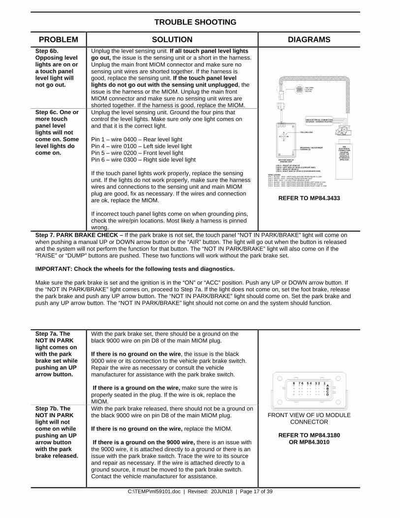
Unplug the level sensing unit. Ground the four pins that control the level lights. Make sure only one light comes on and that it is the correct light. Pin 1 – wire 0400 – Rear level light Pin 4 – wire 0100 – Left side level light Pin 5 – wire 0200 – Front level light Pin 6 – wire 0300 – Right side level light If the touch panel lights work properly, replace the sensing unit. If the lights do not work properly, make sure the harness wires and connections to the sensing unit and main MIOM plug are good, fix as necessary. If the wires and connection are ok, replace the MIOM. If incorrect touch panel lights come on when grounding pins, check the wire/pin locations. Most likely a harness is pinned wrong.
SEE WIRELEGENDBELOW
PIN 1 - BLACK - 0400 - SWITCHED GROUND WHEN REAR IS LOWPIN 2 - WHITE - 6231 - GROUND FROM SENSING UNITPIN 3 - RED - 6121 - +12 VOLT FOR SENSING UNITPIN 4 - BLACK - 0100 - SWITCHED GROUND WHEN LEFT SIDE IS LOWPIN 5 - BLACK - 0200 - SWITCHED GROUND WHEN FRONT IS LOWPIN 6 - BLACK - 0300 - SWITCHED GROUND WHEN RIGHT SIDE IS LOW
SEEELECTRICALCONNECTION
DIAGRAMFRONT AIRMANIFOLD
I/O MODULEMP84.3180
SEE ELECTRICAL CONNECTIONDIAGRAM - HARNESS ROUTING
MOUNTING / ADJUSTMENTSCREWS (3)
A
BD
C
YELLOW LEDS
BOTTOM VIEW OFSENSING UNIT
LED A - FRONT OF VEHICLELED B - LEFT SIDE OF VEHICLE (DRIVER SIDE)LED C - REAR OF VEHICLELED D - RIGHT SIDE OF VEHICLE (PASSENGER SIDE)
WIRE LEGEND
1 2 3654
REFER TO MP84.3433
Step 7. PARK BRAKE CHECK – If the park brake is not set, the touch panel “NOT IN PARK/BRAKE” light will come on when pushing a manual UP or DOWN arrow button or the “AIR” button. The light will go out when the button is released and the system will not perform the function for that button. The “NOT IN PARK/BRAKE” light will also come on if the “RAISE” or “DUMP” buttons are pushed. These two functions will work without the park brake set. IMPORTANT: Chock the wheels for the following tests and diagnostics. Make sure the park brake is set and the ignition is in the “ON” or “ACC” position. Push any UP or DOWN arrow button. If the “NOT IN PARK/BRAKE” light comes on, proceed to Step 7a. If the light does not come on, set the foot brake, release the park brake and push any UP arrow button. The “NOT IN PARK/BRAKE” light should come on. Set the park brake and push any UP arrow button. The “NOT IN PARK/BRAKE” light should not come on and the system should function.
Step 7a. The NOT IN PARK light comes on with the park brake set while pushing an UP arrow button.
With the park brake set, there should be a ground on the black 9000 wire on pin D8 of the main MIOM plug. If there is no ground on the wire, the issue is the black 9000 wire or its connection to the vehicle park brake switch. Repair the wire as necessary or consult the vehicle manufacturer for assistance with the park brake switch. If there is a ground on the wire, make sure the wire is properly seated in the plug. If the wire is ok, replace the MIOM.
Step 7b. The NOT IN PARK light will not come on while pushing an UP arrow button with the park brake released.
With the park brake released, there should not be a ground on the black 9000 wire on pin D8 of the main MIOM plug. If there is no ground on the wire, replace the MIOM. If there is a ground on the 9000 wire, there is an issue with the 9000 wire, it is attached directly to a ground or there is an issue with the park brake switch. Trace the wire to its source and repair as necessary. If the wire is attached directly to a ground source, it must be moved to the park brake switch. Contact the vehicle manufacturer for assistance.
8 7 6 5 4 3 2 1ABCD
FRONT VIEW OF I/O MODULE
CONNECTOR
REFER TO MP84.3180 OR MP84.3010
C:\TEMP\ml59101.doc | Revised: 20JUN18 | Page 18 of 39
TROUBLE SHOOTING
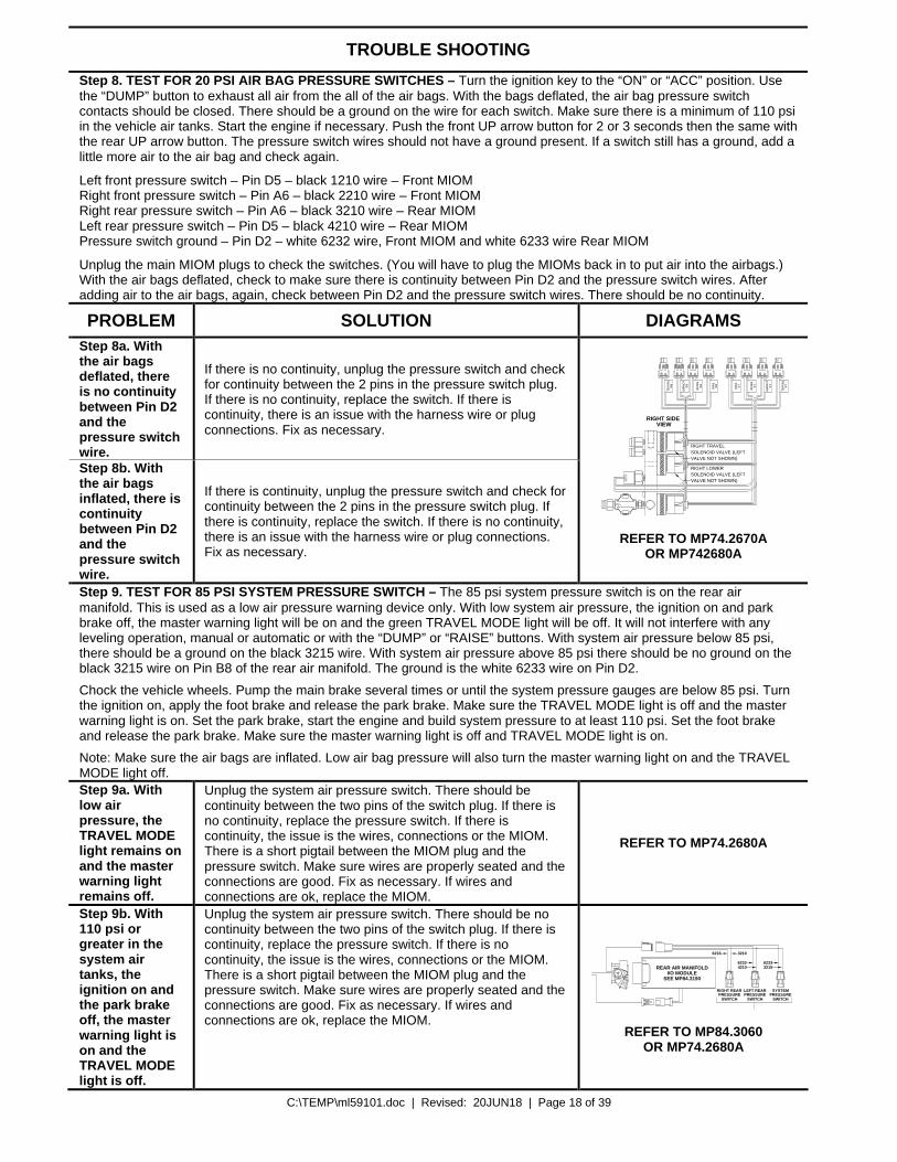
Step 8. TEST FOR 20 PSI AIR BAG PRESSURE SWITCHES – Turn the ignition key to the “ON” or “ACC” position. Use the “DUMP” button to exhaust all air from the all of the air bags. With the bags deflated, the air bag pressure switch contacts should be closed. There should be a ground on the wire for each switch. Make sure there is a minimum of 110 psi in the vehicle air tanks. Start the engine if necessary. Push the front UP arrow button for 2 or 3 seconds then the same with the rear UP arrow button. The pressure switch wires should not have a ground present. If a switch still has a ground, add a little more air to the air bag and check again.
Left front pressure switch – Pin D5 – black 1210 wire – Front MIOM Right front pressure switch – Pin A6 – black 2210 wire – Front MIOM Right rear pressure switch – Pin A6 – black 3210 wire – Rear MIOM Left rear pressure switch – Pin D5 – black 4210 wire – Rear MIOM Pressure switch ground – Pin D2 – white 6232 wire, Front MIOM and white 6233 wire Rear MIOM
Unplug the main MIOM plugs to check the switches. (You will have to plug the MIOMs back in to put air into the airbags.) With the air bags deflated, check to make sure there is continuity between Pin D2 and the pressure switch wires. After adding air to the air bags, again, check between Pin D2 and the pressure switch wires. There should be no continuity.
PROBLEM SOLUTION DIAGRAMS Step 8a. With the air bags deflated, there is no continuity between Pin D2 and the pressure switch wire.
If there is no continuity, unplug the pressure switch and check for continuity between the 2 pins in the pressure switch plug. If there is no continuity, replace the switch. If there is continuity, there is an issue with the harness wire or plug connections. Fix as necessary.
Step 8b. With the air bags inflated, there is continuity between Pin D2 and the pressure switch wire.
If there is continuity, unplug the pressure switch and check for continuity between the 2 pins in the pressure switch plug. If there is continuity, replace the switch. If there is no continuity, there is an issue with the harness wire or plug connections. Fix as necessary.
RIGHT SIDE VIEW
VALVE NOT SHOWN)
RIGHT TRAVELSOLENOID VALVE (LEFTVALVE NOT SHOWN)
RIGHT LOWERSOLENOID VALVE (LEFT
RA
ISE
RS
LOW
ER
RS
RS
TR
AV
EL
LST
RA
VE
L
LOW
ER
LS
RA
ISE
LS
PS
WLS
PS
WR
S
AAB B A B A B B A B A B BA A
NA
SO
NM
OD
EL
SM
REFER TO MP74.2670A OR MP742680A
Step 9. TEST FOR 85 PSI SYSTEM PRESSURE SWITCH – The 85 psi system pressure switch is on the rear air manifold. This is used as a low air pressure warning device only. With low system air pressure, the ignition on and park brake off, the master warning light will be on and the green TRAVEL MODE light will be off. It will not interfere with any leveling operation, manual or automatic or with the “DUMP” or “RAISE” buttons. With system air pressure below 85 psi, there should be a ground on the black 3215 wire. With system air pressure above 85 psi there should be no ground on the black 3215 wire on Pin B8 of the rear air manifold. The ground is the white 6233 wire on Pin D2.
Chock the vehicle wheels. Pump the main brake several times or until the system pressure gauges are below 85 psi. Turn the ignition on, apply the foot brake and release the park brake. Make sure the TRAVEL MODE light is off and the master warning light is on. Set the park brake, start the engine and build system pressure to at least 110 psi. Set the foot brake and release the park brake. Make sure the master warning light is off and TRAVEL MODE light is on.
Note: Make sure the air bags are inflated. Low air bag pressure will also turn the master warning light on and the TRAVEL MODE light off. Step 9a. With low air pressure, the TRAVEL MODE light remains on and the master warning light remains off.
Unplug the system air pressure switch. There should be continuity between the two pins of the switch plug. If there is no continuity, replace the pressure switch. If there is continuity, the issue is the wires, connections or the MIOM. There is a short pigtail between the MIOM plug and the pressure switch. Make sure wires are properly seated and the connections are good. Fix as necessary. If wires and connections are ok, replace the MIOM.
REFER TO MP74.2680A
Step 9b. With 110 psi or greater in the system air tanks, the ignition on and the park brake off, the master warning light is on and the TRAVEL MODE light is off.
Unplug the system air pressure switch. There should be no continuity between the two pins of the switch plug. If there is continuity, replace the pressure switch. If there is no continuity, the issue is the wires, connections or the MIOM. There is a short pigtail between the MIOM plug and the pressure switch. Make sure wires are properly seated and the connections are good. Fix as necessary. If wires and connections are ok, replace the MIOM.
BA
SEE MP84.3190I/O MODULE
REAR AIR MANIFOLD
SYSTEMPRESSURE
SWITCH
A B BA
SWITCH
RIGHT REARPRESSURE
LEFT REARPRESSURE
SWITCH
6233 623332154210
6233 3210
REFER TO MP84.3060 OR MP74.2680A
C:\TEMP\ml59101.doc | Revised: 20JUN18 | Page 19 of 39
TROUBLE SHOOTING
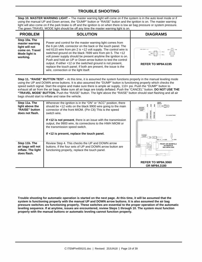
Step 10. MASTER WARNING LIGHT – The master warning light will come on if the system is in the auto level mode or if using the manual UP and Down arrows, the “DUMP” button or “RAISE” button and the ignition is on. The master warning light will also come on if the park brake is off and the ignition is on when there is low air bag pressure or system pressure. The green TRAVEL MODE light should be off any time the master warning light is on.
PROBLEM SOLUTION DIAGRAMS Step 10a. The master warning light will not come on. Travel Mode light is working.
Power and control for the master warning light comes from the 6 pin UML connector on the back or the touch panel. The red 6110 wire from pin 2 is +12 volt supply. The control wire is switched ground on the black 7699 wire from pin 5. The +12 volt power supply should be present anytime the ignition is on. Push and hold an UP or Down arrow button to test the control output. If either +12 or the switched ground is not present, replace the touch panel. If both are present, the issue is the wire, connection or the light itself.
LINK LIGHT
PIN 4 PIN 1
PIN 6CN2
PIN 3
6110 7699
REFER TO MP84.6195
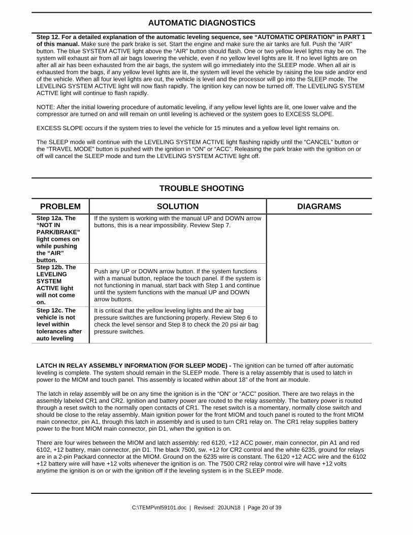
Step 11. “RAISE” BUTTON TEST – At this time, it is assumed the system functions properly in the manual leveling mode using the UP and DOWN arrow buttons. It is also assumed the “DUMP” button is functioning properly which checks the speed switch signal. Start the engine and make sure there is ample air supply, 110+ psi. Push the “DUMP” button to exhaust all air from the air bags. Make sure all air bags are totally deflated. Push the “CANCEL” button. DO NOT USE THE “TRAVEL MODE’ BUTTON. Push the “RAISE” button. The light above the “RAISE” button should start flashing and all air bags should start to inflate and raise the vehicle.
Step 11a. The light above the “RAISE” button does not flash.
Whenever the ignition is in the “ON” or “ACC” position, there should be +12 volts on the black 9900 wire going to the main connector of the front MIOM. (Pin C6) This is the speed switch wire. If +12 is not present, there is an issue with the transmission output, the 9900 wire, its connections to the HWH MIOM or the transmission speed switch. If +12 is present, replace the touch panel.
Step 11b. The air bags will not inflate. The light does flash.
Review Step 4. This checks the UP and DOWN arrow buttons. If the four sets of UP and DOWN arrow button are functioning properly, replace the touch panel.
AB
I/O MODULESEE MP84.3180
62357500 9700
TO +12 BATTERY
GR
OU
ND
PA
RK
BR
AK
E
SP
EE
D S
W
MASTERWARNING
LIGHT
6230
9000
9900
LATCHSYSTEM
RESETSWITCH
6101
6100
REFER TO MP84.3060 OR MP84.3180
Trouble shooting for automatic operation is started on the next page. At this time, it will be assumed that the system is functioning properly with the manual UP and DOWN arrow buttons. It is also assumed the air bag pressure switches are functioning properly. These switches are essential to the proper operation of the automatic leveling sequence. If at anytime, issues are encountered, review Steps 1 through 10. The system must function properly with the manual buttons or automatic leveling cannot function properly.
C:\TEMP\ml59101.doc | Revised: 20JUN18 | Page 20 of 39
AUTOMATIC DIAGNOSTICS
Step 12. For a detailed explanation of the automatic leveling sequence, see “AUTOMATIC OPERATION” in PART 1 of this manual. Make sure the park brake is set. Start the engine and make sure the air tanks are full. Push the “AIR” button. The blue SYSTEM ACTIVE light above the “AIR” button should flash. One or two yellow level lights may be on. The system will exhaust air from all air bags lowering the vehicle, even if no yellow level lights are lit. If no level lights are on after all air has been exhausted from the air bags, the system will go immediately into the SLEEP mode. When all air is exhausted from the bags, if any yellow level lights are lit, the system will level the vehicle by raising the low side and/or end of the vehicle. When all four level lights are out, the vehicle is level and the processor will go into the SLEEP mode. The LEVELING SYSTEM ACTIVE light will now flash rapidly. The ignition key can now be turned off. The LEVELING SYSTEM ACTIVE light will continue to flash rapidly. NOTE: After the initial lowering procedure of automatic leveling, if any yellow level lights are lit, one lower valve and the compressor are turned on and will remain on until leveling is achieved or the system goes to EXCESS SLOPE. EXCESS SLOPE occurs if the system tries to level the vehicle for 15 minutes and a yellow level light remains on. The SLEEP mode will continue with the LEVELING SYSTEM ACTIVE light flashing rapidly until the “CANCEL” button or the “TRAVEL MODE” button is pushed with the ignition in “ON” or “ACC”. Releasing the park brake with the ignition on or off will cancel the SLEEP mode and turn the LEVELING SYSTEM ACTIVE light off.
TROUBLE SHOOTING
PROBLEM SOLUTION DIAGRAMS Step 12a. The “NOT IN PARK/BRAKE” light comes on while pushing the “AIR” button.
If the system is working with the manual UP and DOWN arrow buttons, this is a near impossibility. Review Step 7.
Step 12b. The LEVELING SYSTEM ACTIVE light will not come on.
Push any UP or DOWN arrow button. If the system functions with a manual button, replace the touch panel. If the system is not functioning in manual, start back with Step 1 and continue until the system functions with the manual UP and DOWN arrow buttons.
Step 12c. The vehicle is not level within tolerances after auto leveling
It is critical that the yellow leveling lights and the air bag pressure switches are functioning properly. Review Step 6 to check the level sensor and Step 8 to check the 20 psi air bag pressure switches.
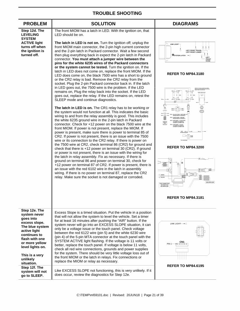
LATCH IN RELAY ASSEMBLY INFORMATION (FOR SLEEP MODE) - The ignition can be turned off after automatic leveling is complete. The system should remain in the SLEEP mode. There is a relay assembly that is used to latch in power to the MIOM and touch panel. This assembly is located within about 18” of the front air module. The latch in relay assembly will be on any time the ignition is in the “ON” or “ACC” position. There are two relays in the assembly labeled CR1 and CR2. Ignition and battery power are routed to the relay assembly. The battery power is routed through a reset switch to the normally open contacts of CR1. The reset switch is a momentary, normally close switch and should be close to the relay assembly. Main ignition power for the front MIOM and touch panel is routed to the front MIOM main connector, pin A1, through this latch in assembly and is used to turn CR1 relay on. The CR1 relay supplies battery power to the front MIOM main connector, pin D1, when the ignition is on. There are four wires between the MIOM and latch assembly: red 6120, +12 ACC power, main connector, pin A1 and red 6102, +12 battery, main connector, pin D1. The black 7500, sw. +12 for CR2 control and the white 6235, ground for relays are in a 2-pin Packard connector at the MIOM. Ground on the 6235 wire is constant. The 6120 +12 ACC wire and the 6102 +12 battery wire will have +12 volts whenever the ignition is on. The 7500 CR2 relay control wire will have +12 volts anytime the ignition is on or with the ignition off if the leveling system is in the SLEEP mode.
C:\TEMP\ml59101.doc | Revised: 20JUN18 | Page 21 of 39
TROUBLE SHOOTING
PROBLEM SOLUTION DIAGRAMS
LINK LIGHT
LEFT FRONT LOWERLEFT FRONT TRAVEL
SYSTEM LATCH* LEFTFRONTRAISE
REFER TO MP84.3180
62356101
6102
6101 6235
6102 7500
62356120
61027500
FRONT I/OMODULE
SEEMP84.3181
6120
6102
7500
6235
REFER TO VEHICLE MANUFACTURERFOR RELAY MOUNTING LOCATION ANDRESET SWITCH LOCATION
RESET SWITCH (NC)
61006101
6101
6120
6101 6100ACCTO +12 ACCESSORY
TO +12 BATTERY
6120
BA
CR1 CR2
FUSE5 AMP
PIN 4 - RED (6120) - +12 ACC.TO FRONT I/O MODULEHARNESS CONNECTOR
HARNESS CONNECTORTO FRONT I/O MODULE
PIN 3 - RED (6102) - +12 BATTERY
PIN 1 - BLACK (7500) - SWITCHED +12FROM FRONT I/O MODULE
FROM FRONT I/O MODULEPIN 2 - WHITE (6235) - GROUND
PIN 4PIN 3 PIN 2
PIN 1
87 85
8630
8587
30 86
REFER TO MP84.3200
Step 12d. The LEVELING SYSTEM ACTIVE light turns off when the ignition is turned off.
The front MIOM has a latch in LED. With the ignition on, that LED should be on. The latch in LED is not on. Turn the ignition off; unplug the front MIOM main connector, the 2-pin high current connector and the 2-pin latch in Packard connector. Wait a few second then plug everything back in expect the 2-pin latch in Packard connector. You must attach a jumper wire between the pins for the white 6235 wires of the Packard connectors or the system cannot be tested. Turn the ignition on. If the latch in LED does not come on, replace the front MIOM. If the LED does come on, the black 7500 wire has a short to ground or the CR2 relay is bad. Remove the CR2 relay from the socket. Plug the 2-pin Packard connector back in. If the latch in LED goes out, the 7500 wire is the problem. If the LED remains on, Plug the relay back into the socket. If the LED goes out, replace the relay. If the LED remains on, retest the SLEEP mode and continue diagnostics. The latch in LED is on. The CR1 relay has to be working or the system would not function at all. This indicates the basic wiring to and from the relay assembly is good. This includes the white 6235 ground wire in the 2-pin latch in Packard connector. Check for +12 power on the black 7500 wire at the front MIOM. If power is not present, replace the MIOM. If power is present, make sure there is power to terminal 85 of CR2. If power is not present, there is an issue with the 7500 wire or its connection to the CR2 relay. If there is power on the 7500 wire at CR2, check terminal 86 (CR2) for ground and check that there is +12 power on terminal 30 (CR2). If ground or power is not present, there is an issue with the wiring for the latch in relay assembly. Fix as necessary. If there is ground on terminal 86 and power on terminal 30, check for +12 power on terminal 87 of CR2. If power is present, there is an issue with the red 6102 wire in the latch in assembly wiring. If there is no power on terminal 87, replace the CR2 relay. Make sure the socket is not damaged or corroded.
CONTROLW9700
RELAY COMP
W7500RELAYLATCH
BA
BA
SEE MP84.3200
SEE MP84.3180INFORMATION
FOR CONNECTION
6235750061026120
15006242
WHITE
BLACK
REFER TO MP84.3181
Step 12e. The system never goes into excess slope. The blue system active light continues to flash with one or more yellow level lights on. This is a very unlikely situation.
Excess Slope is a timed situation. Put the vehicle in a position that will not allow the system to level the vehicle. Set a timer for at least 16 minutes after pushing the “AIR” button. If the system never will go into an EXCESS SLOPE situation, it can only be a voltage issue or the touch panel. Check voltage between the red 6122 wire (pin 5) and the white 6230 wire (pin 4) of the 5-pin MTA connector at the touch panel with the SYSTEM ACTIVE light flashing. If the voltage is 11 volts or better, replace the touch panel. If voltage is below 11 volts, check all red wire connections, grounds and power supplies for the system. There should be very little voltage loss out of the front MIOM or the latch in relays. Fix connections or replace the MIOM or relay as necessary.
Step 12f. The system will not go to SLEEP.
Like EXCESS SLOPE not functioning, this is very unlikely. If it does occur, review the diagnostics for Step 12e.
LINK LIGHT
PIN 1CN1
REFER TO MP84.6195
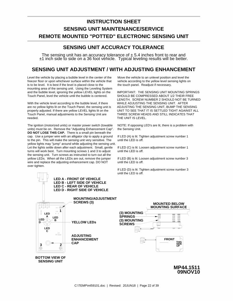
C:\TEMP\ml59101.doc | Revised: 20JUN18 | Page 22 of 39
SENSING UNIT MAINTENANCE/SERVICE
SENSING UNIT ADJUSTMENT / WITH ADJUSTING ENHANCEMENT
NOTE: If opposing LED's are lit, there is a problem withthe Sensing Unit.
If LED (A) is lit: Tighten adjustment screw number 1until the LED is off.
If LED (C) is lit: Loosen adjustment screw number 1until the LED is off.
If LED (B) is lit: Loosen adjustment screw number 3until the LED is off.
until the LED is off.If LED (D) is lit: Tighten adjustment screw number 3
09NOV10MP44.1511
With the vehicle level according to the bubble level, if there are no yellow lights lit on the Touch Panel, the sensing unit is properly adjusted. If there are yellow LEVEL lights lit on the Touch Panel, manual adjustments to the Sensing Unit are needed.
SENSING UNIT ACCURACY TOLERANCEThe sensing unit has an accuracy tolerance of ± 5.4 inches front to rear and
INSTRUCTION SHEET
±1 inch side to side on a 36 foot vehicle. Typical leveling results will be better.
IMPORTANT: THE SENSING UNIT MOUNTING SPRINGSSHOULD BE COMPRESSED ABOUT 1/2 THEIR FREELENGTH. SCREW NUMBER 2 SHOULD NOT BE TURNED
MOUNTED BELOW
FRONT
MOUNTING SURFACE
(3) MOUNTING
(3) MOUNTING
SCREWS
SPRINGS
THISSIDEUP
LED A - FRONT OF VEHICLELED B - LEFT SIDE OF VEHICLELED C - REAR OF VEHICLELED D - RIGHT SIDE OF VEHICLE
REMOTE MOUNTED "POTTED" ELECTRONIC SENSING UNIT
WHILE ADJUSTING THE SENSING UNIT. AFTERADJUSTING THE SENSING UNIT, BUMP THE SENSINGUNIT TO SEE THAT IT IS SETTLED TIGHT AGAINST ALLTHREE SCREW HEADS AND STILL INDICATES THATTHE UNIT IS LEVEL.
Level the vehicle by placing a bubble level in the center of the freezer floor or upon whichever surface within the vehicle that is to be level. It is best if the level is placed close to the mounting area of the sensing unit. Using the Leveling System and the bubble level, ignoring the yellow LEVEL lights on the Touch Panel, level the vehicle until the bubble is centered.
The ignition (motorized units) or master power switch (towableunits) must be on. Remove the "Adjusting Enhancement Cap".DO NOT LOSE THIS CAP. There is a small pin beneath thecap. Use a jumper wire with an alligator clip to apply a groundto the pin. This will make the sensing unit very sensitive. Theyellow lights may "jump" around while adjusting the sensing unit.Let the lights settle down after each adjustment. Small, gentleturns will work best. Turn mounting screws 1 and 3 to adjustthe sensing unit. Turn screws as instructed to turn out all theyellow LEDs. When all the LEDs are out, remove the jumperwire and replace the adjusting enhancement cap. DO NOTover tighten.
SENSING UNITBOTTOM VIEW OF
LED
3
D
CLED
LEDA
BYELLOW LEDs
2
MOUNTING/ADJUSTMENTSCREWS (3)
1
LED
Move the vehicle to an unlevel position and level thevehicle according to the yellow level sensing lights onthe touch panel. Readjust if necessary.
ADJUSTINGENHANCEMENTCAP
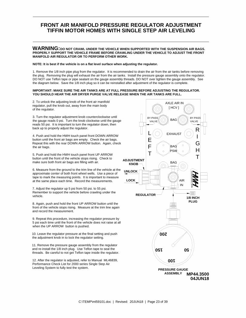
C:\TEMP\ml59101.doc | Revised: 20JUN18 | Page 23 of 39
MP44.350004JUN18
TIFFIN MOTOR HOMES WITH SINGLE STEP AIR LEVELINGFRONT AIR MANIFOLD PRESSURE REGULATOR ADJUSTMENT
DO NOT CRAWL UNDER THE VEHICLE WHEN SUPPORTED WITH THE SUSPENSION AIR BAGS.PROPERLY SUPPORT THE VEHICLE FRAME BEFORE CRAWLING UNDER THE VEHICLE TO ADJUST THE FRONTWARNING:MANIFOLD AIR REGULATOR OR TO PERFORM OTHER WORK.
NOTE: It is best if the vehicle is on a flat level surface when adjusting the regulator.
1. Remove the 1/8 inch pipe plug from the regulator. It is recommended to drain the air from the air tanks before removing the plug. Removing the plug will exhaust the air from the air tanks. Install the pressure gauge assembly onto the regulator.
IMPORTANT: MAKE SURE THE AIR TANKS ARE AT FULL PRESSURE BEFORE ADJUSTING THE REGULATOR.YOU SHOULD HEAR THE AIR DRYER PURGE VALVE RELEASE WHEN THE AIR TANKS ARE FULL.
R
12. After the regulator is adjusted, refer to Manual ML46839, Performance Check List for 2000 series Single Step Air Leveling System to fully test the system.
11. Remove the pressure gauge assembly from the regulator and re-install the 1/8 inch plug. Use Teflon tape to seal the threads. Be careful to not get Teflon tape inside the regulator.
10. Leave the regulator pressure at the final setting and push the adjustment knob in to lock the regulator setting.
9. Repeat this procedure, increasing the regulator pressure by 5 psi each time until the front of the vehicle does not raise at all when the UP ARROW button is pushed.
7. Adjust the regulator up 5 psi from 50 psi. to 55 psi. Remember to support the vehicle before crawling under the
8. Again, push and hold the front UP ARROW button until the front of the vehicle stops rising. Measure at the trim line again and record the measurement.
6. Measure from the ground to the trim line of the vehicle at the approximate center of both front wheel wells. Use a piece of tape to mark the measuring points. It is important to measure at the same place each time. Record the measurements.
5. Push and hold the HWH touch panel front UP ARROW button until the front of the vehicle stops rising. Check to make sure both front air bags are filling with air.
4. Push and hold the HWH touch panel front DOWN ARROW button until the front air bags are empty. Check the air bags. Repeat this with the rear DOWN ARROW button. Again, check the air bags.
3. Turn the regulator adjustment knob counterclockwise until the gauge reads 0 psi. Turn the knob clockwise until the gauge reads 50 psi. It is important to turn the regulator down, then back up to properly adjust the regulator.
2. To unlock the adjusting knob of the front air manifold regulator, pull the knob out, away from the main bodyof the regulator.
PRESSURE GAUGE
50
100
150
200
AXLE AIR IN[ HCV ]
BY-PASSVALVE BAG
BY-PASSVALVE
EXHAUST
BAGPSW
LEFT
RIGHT
BAG
AIRIN
ASSEMBLY
1/8 INCHPLUG
REGULATOR
KNOBADJUSTMENT
UNLOCK
LOCK
DO NOT use Teflon tape or pipe sealant on the gauge assembly threads. DO NOT over tighten the gauge assembly. Seethe diagram below. Save the 1/8 inch plug so it can be reinstalled after adjustment of the regulator is complete.
vehicle.
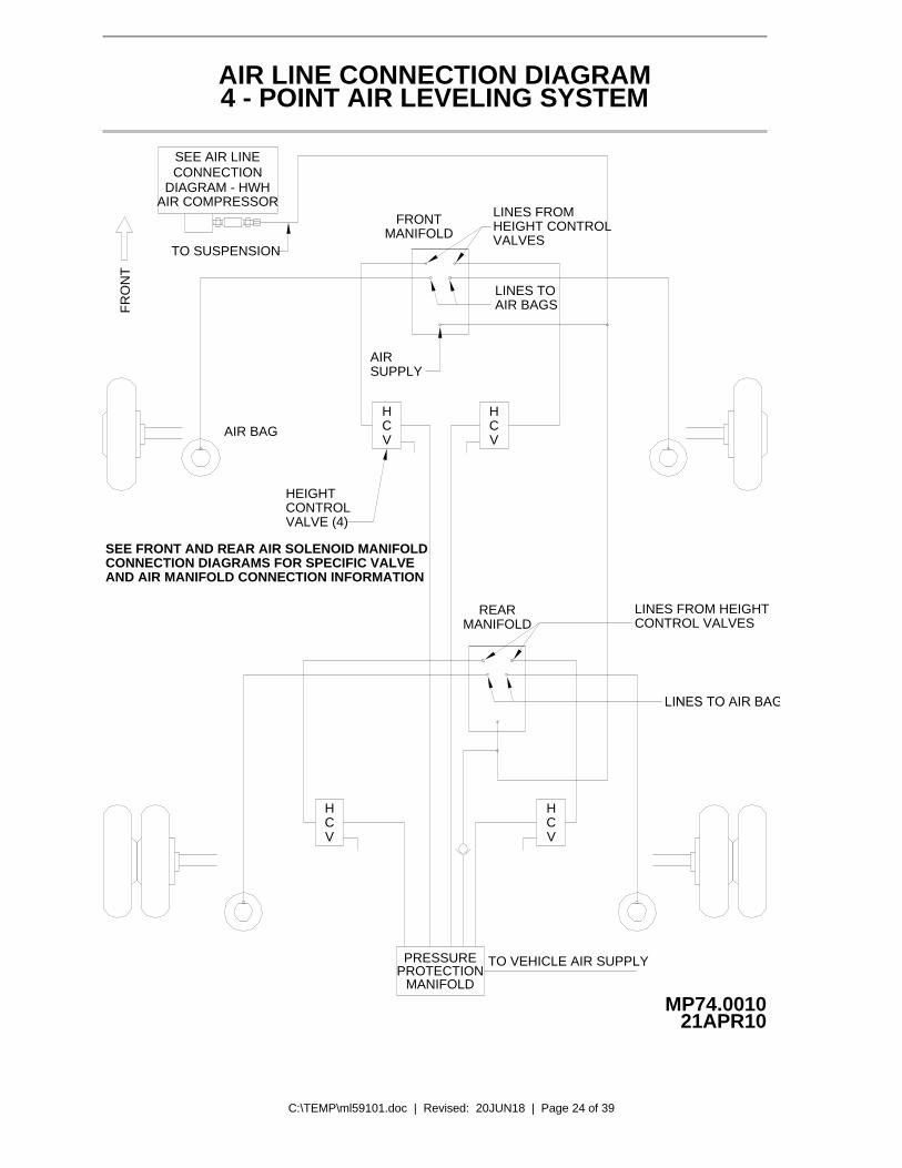
C:\TEMP\ml59101.doc | Revised: 20JUN18 | Page 24 of 39
4 - POINT AIR LEVELING SYSTEM
MP74.001021APR10
FR
ON
T
CONNECTION
TO SUSPENSION
FRONT
AIR BAG
AIR LINE CONNECTION DIAGRAM
DIAGRAM - HWHAIR COMPRESSOR
SEE AIR LINE
HCV
HCV
CV
HCV
H
PRESSUREPROTECTION
MANIFOLD
TO VEHICLE AIR SUPPLY
SEE FRONT AND REAR AIR SOLENOID MANIFOLDCONNECTION DIAGRAMS FOR SPECIFIC VALVEAND AIR MANIFOLD CONNECTION INFORMATION
HEIGHTCONTROLVALVE (4)
AIRSUPPLY
MANIFOLDREAR LINES FROM HEIGHT
CONTROL VALVES
HEIGHT CONTROLLINES FROM
MANIFOLD
AIR BAGS
VALVES
LINES TO
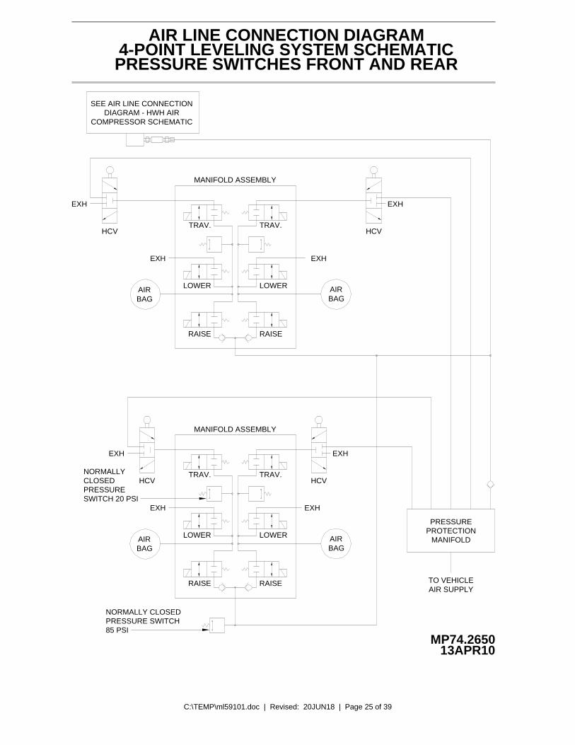
C:\TEMP\ml59101.doc | Revised: 20JUN18 | Page 25 of 39
AIRBAG
AIRBAG
MANIFOLD ASSEMBLY
EXHEXH
HCVHCV
4-POINT LEVELING SYSTEM SCHEMATICPRESSURE SWITCHES FRONT AND REAR
MP74.265013APR10
RAISE
LOWER
TRAV.
RAISE
LOWER
TRAV.
EXH EXH
AIR LINE CONNECTION DIAGRAM
MANIFOLD ASSEMBLY
SEE AIR LINE CONNECTIONDIAGRAM - HWH AIR
COMPRESSOR SCHEMATIC
EXH
HCV
EXH
HCV
LOWER
TRAV.
LOWER
RAISE
AIRBAG
EXH
RAISE
TRAV.
EXH
AIRBAG
NORMALLY CLOSEDPRESSURE SWITCH
PRESSUREPROTECTION
MANIFOLD
TO VEHICLEAIR SUPPLY
85 PSI
PRESSURECLOSEDNORMALLY
SWITCH 20 PSI
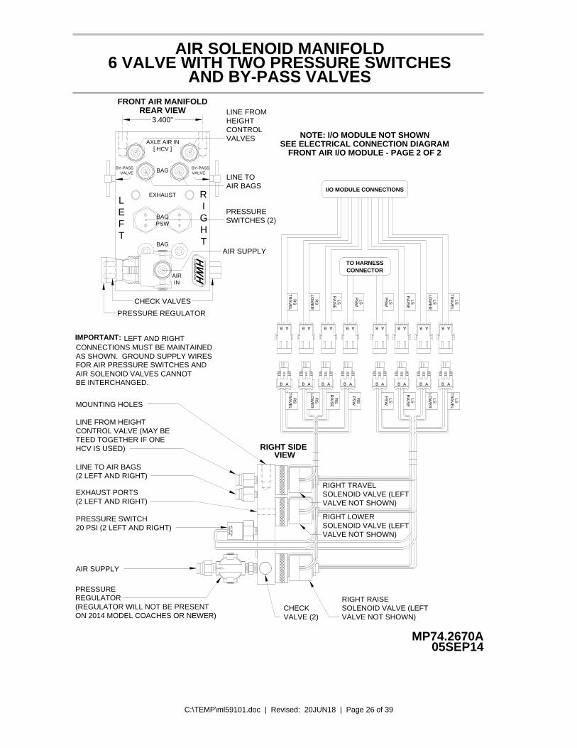
C:\TEMP\ml59101.doc | Revised: 20JUN18 | Page 26 of 39
MP74.2670A05SEP14
AIR SOLENOID MANIFOLD6 VALVE WITH TWO PRESSURE SWITCHES
AND BY-PASS VALVES
EXHAUST
AXLE AIR IN[ HCV ]
LEFT
BY-PASSVALVE
RIGHT
AIRIN
BAG
R
BAGPSW
BY-PASSVALVEBAG
CHECK VALVES
AIR SUPPLY
AIR BAGSLINE TO
CONTROLHEIGHTLINE FROM
VALVES
3.400"
FRONT AIR MANIFOLD
RIGHT SIDE VIEW
LEFT AND RIGHT
MOUNTING HOLES
LINE FROM HEIGHTCONTROL VALVE (MAY BETEED TOGETHER IF ONE
EXHAUST PORTS(2 LEFT AND RIGHT)
PRESSURE SWITCH20 PSI (2 LEFT AND RIGHT)
LINE TO AIR BAGS(2 LEFT AND RIGHT)
BE INTERCHANGED.AIR SOLENOID VALVES CANNOT FOR AIR PRESSURE SWITCHES ANDAS SHOWN. GROUND SUPPLY WIRESCONNECTIONS MUST BE MAINTAINED
PRESSUREREGULATOR
AIR SUPPLY
HCV IS USED)
IMPORTANT:
SOLENOID VALVE (LEFT
VALVE NOT SHOWN)
VALVE NOT SHOWN)
RIGHT RAISE
VALVE (2)CHECK
RIGHT TRAVELSOLENOID VALVE (LEFTVALVE NOT SHOWN)
RIGHT LOWERSOLENOID VALVE (LEFT
AAB B A B A B
PS
WR
S
B A B A B BA
AB B A AB B A B A AB B BA A
A
NA
SO
NM
OD
EL
SM
REAR VIEW
SWITCHES (2)PRESSURE
PRESSURE REGULATOR
RA
ISE
RS
LOW
ER
RS
RS
TR
AV
EL
LST
RA
VE
L
LOW
ER
LS
RA
ISE
LS
PS
WLS
TR
AV
EL
RS
LOW
ER
RS
PS
WLS
RA
ISE
LS LSLO
WE
R
TR
AV
EL
LS
RA
ISE
LS
PS
WLS
TO HARNESSCONNECTOR
I/O MODULE CONNECTIONS
NOTE: I/O MODULE NOT SHOWNSEE ELECTRICAL CONNECTION DIAGRAM
FRONT AIR I/O MODULE - PAGE 2 OF 2
(REGULATOR WILL NOT BE PRESENTON 2014 MODEL COACHES OR NEWER)
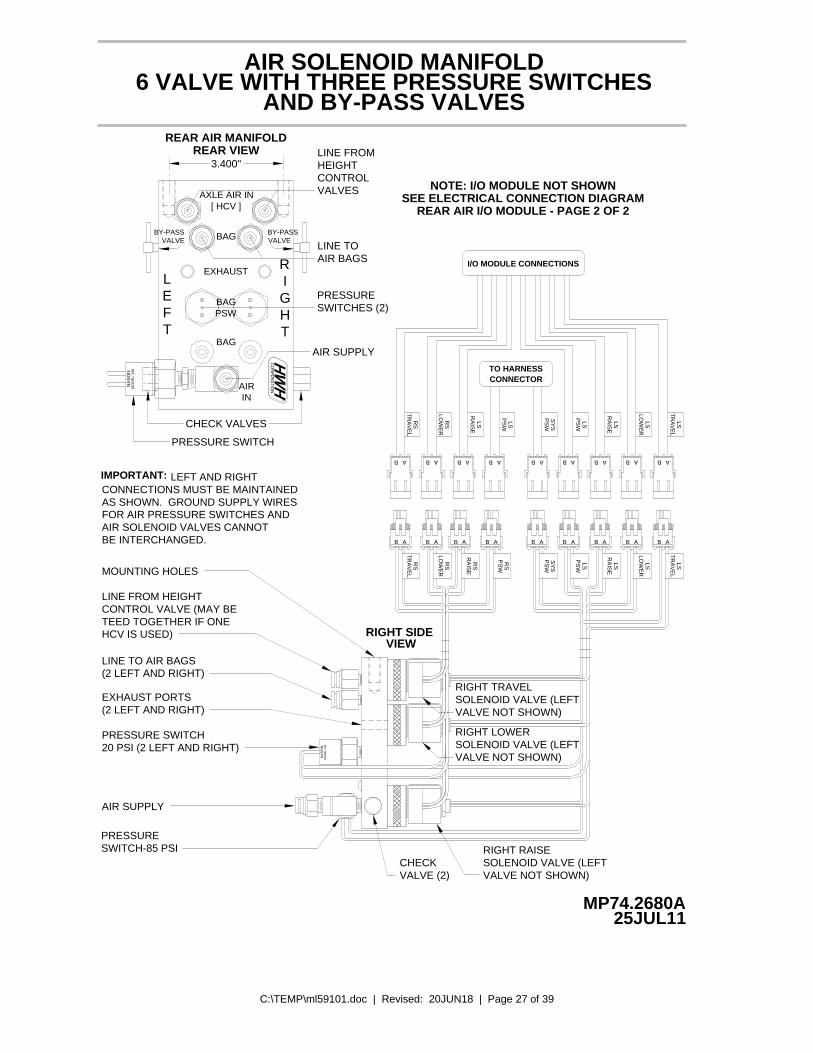
C:\TEMP\ml59101.doc | Revised: 20JUN18 | Page 27 of 39
MP74.2680A25JUL11
AIR SOLENOID MANIFOLD6 VALVE WITH THREE PRESSURE SWITCHES
AND BY-PASS VALVES
EXHAUST
AXLE AIR IN[ HCV ]
MO
DE
L S
MN
AS
ON
LEFT
BY-PASSVALVE
RIGHT
AIRIN
BAG
R
BAGPSW
BY-PASSVALVEBAG
CHECK VALVES
AIR SUPPLY
AIR BAGSLINE TO
CONTROLHEIGHTLINE FROM
VALVES
3.400"
REAR AIR MANIFOLD
PRESSURE SWITCH
RIGHT SIDE VIEW
LEFT AND RIGHT
MOUNTING HOLES
LINE FROM HEIGHTCONTROL VALVE (MAY BETEED TOGETHER IF ONE
EXHAUST PORTS(2 LEFT AND RIGHT)
PRESSURE SWITCH20 PSI (2 LEFT AND RIGHT)
LINE TO AIR BAGS(2 LEFT AND RIGHT)
BE INTERCHANGED.AIR SOLENOID VALVES CANNOT FOR AIR PRESSURE SWITCHES ANDAS SHOWN. GROUND SUPPLY WIRESCONNECTIONS MUST BE MAINTAINED
PRESSURESWITCH-85 PSI
AIR SUPPLY
HCV IS USED)
IMPORTANT:
SOLENOID VALVE (LEFT
VALVE NOT SHOWN)
VALVE NOT SHOWN)
RIGHT RAISE
VALVE (2)CHECK
RIGHT TRAVELSOLENOID VALVE (LEFTVALVE NOT SHOWN)
RIGHT LOWERSOLENOID VALVE (LEFT
AAB B A B A B B A B A B BA
AB B A AB B A B A AB B BA A AB
A AB
NA
SO
NM
OD
EL
SM
REAR VIEW
SWITCHES (2)PRESSURE
REAR AIR I/O MODULE - PAGE 2 OF 2SEE ELECTRICAL CONNECTION DIAGRAM
I/O MODULE CONNECTIONS
CONNECTORTO HARNESS
TR
AV
EL
RS
LOW
ER
RA
ISE
RS
LS LSP
SW
NOTE: I/O MODULE NOT SHOWN
TR
AV
EL
RS
LOW
ER
RA
ISE
RS
RS
RS
PS
W
PS
WLS LS
RA
ISE
LSLO
WE
R
TR
AV
EL
LS
SY
SP
SW
PS
WS
YS
LSP
SW
LSR
AIS
E
LOW
ER
LS LST
RA
VE
L
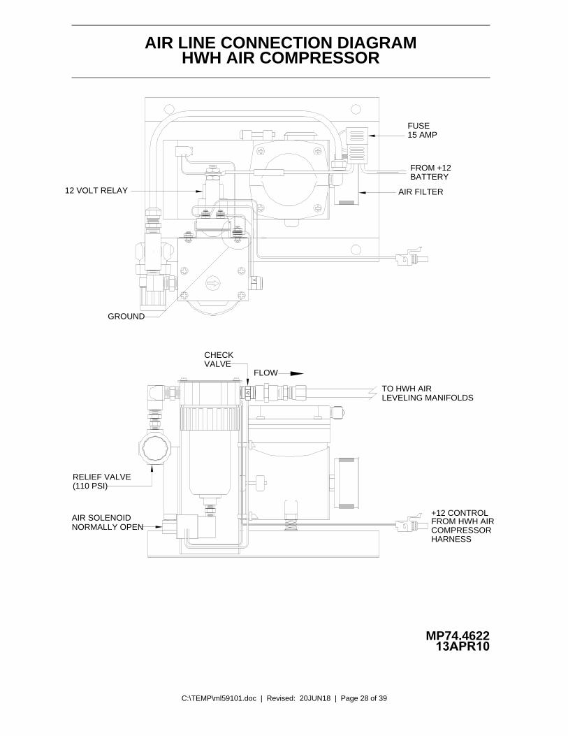
C:\TEMP\ml59101.doc | Revised: 20JUN18 | Page 28 of 39
AIR LINE CONNECTION DIAGRAM
12 VOLT RELAY AIR FILTER
MP74.4622
BATTERY
GROUND
FROM +12
FLOW
RELIEF VALVE(110 PSI)
AIR SOLENOID
TO HWH AIR
+12 CONTROL
COMPRESSORFROM HWH AIR
LEVELING MANIFOLDS
NORMALLY OPEN
HWH AIR COMPRESSOR
HARNESS
15 AMPFUSE
VALVECHECK
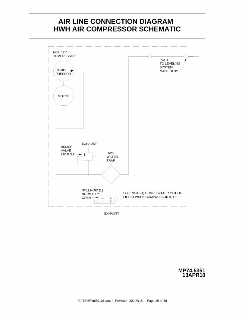
C:\TEMP\ml59101.doc | Revised: 20JUN18 | Page 29 of 39
AIR LINE CONNECTION DIAGRAMHWH AIR COMPRESSOR SCHEMATIC
COMP-PRESSOR
MOTOR
EXHAUST
EXHAUST
SOLENOID (1)NORMALLYOPEN
RELIEFVALVE110 P.S.I.
AUX. 12VCOMPRESSOR
SOLENOID (1) DUMPS WATER OUT OFFILTER WHEN COMPRESSOR IS OFF.
PORTTO LEVELINGSYSTEMMANIFOLDS
HWHWATERTRAP
13APR10MP74.5351
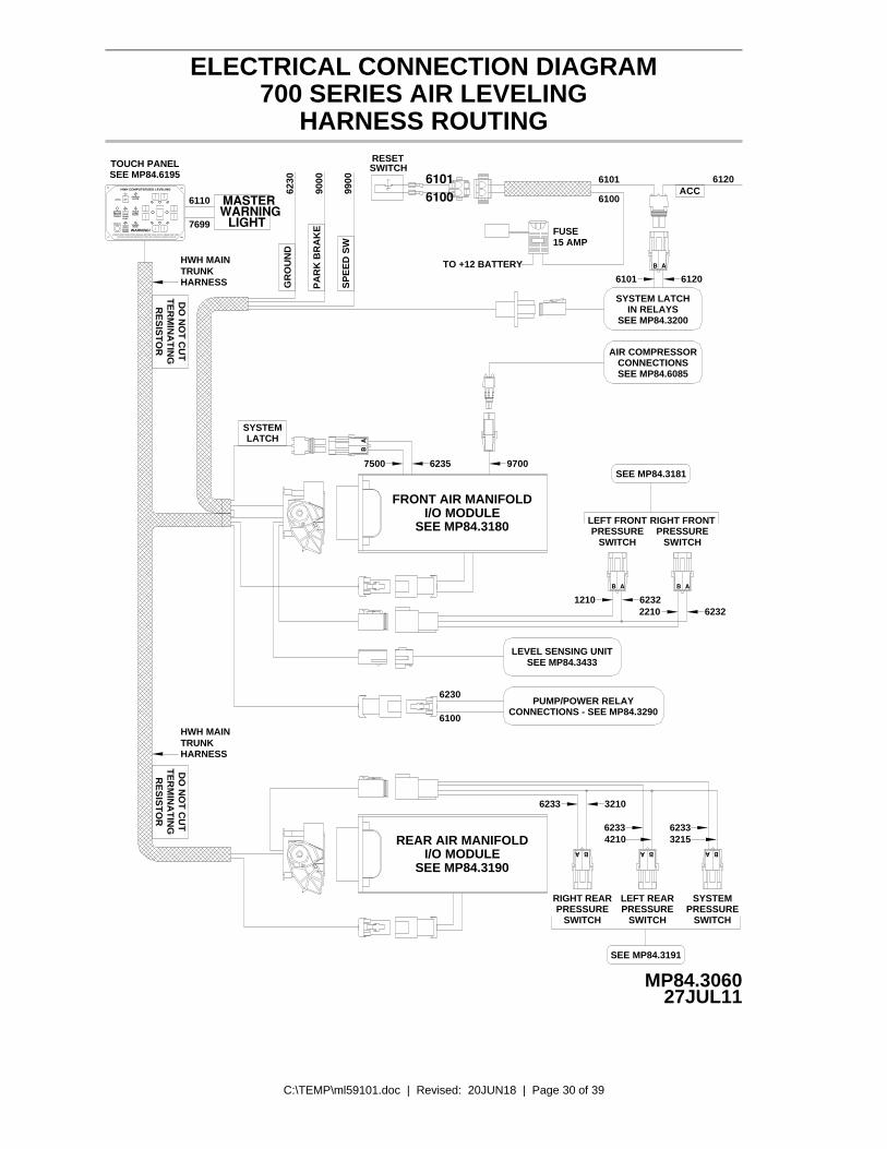
C:\TEMP\ml59101.doc | Revised: 20JUN18 | Page 30 of 39
700 SERIES AIR LEVELING
MP84.306027JUL11
ELECTRICAL CONNECTION DIAGRAM
HARNESS ROUTING
AB
FRONT AIR MANIFOLDI/O MODULE
SEE MP84.3180
62357500 9700
AIR COMPRESSORCONNECTIONSSEE MP84.6085
SYSTEM LATCHIN RELAYS
SEE MP84.3200
AB
61206101
SEE MP84.3190I/O MODULE
REAR AIR MANIFOLD
FUSE15 AMP
6100
6120ACC
6101
62321210
B A
6232
B A
2210
LEFT FRONTPRESSURE
SWITCHPRESSURE
RIGHT FRONT
SWITCH
LEVEL SENSING UNITSEE MP84.3433
SWITCH
RIGHT REARPRESSURE
6233
B
LEFT REARPRESSURE
SWITCH
3210
A
SYSTEMPRESSURE
SWITCH
A B BA
6233 623332154210
PUMP/POWER RELAYCONNECTIONS - SEE MP84.3290
6230
6100
HWH COMPUTERIZED LEVELING
WARNING!UNDERSTAND OPERATOR'S MANUAL BEFORE USING. BLOCK FRAME AND TIRES
SECURELY BEFORE REMOVING TIRES OR CRAWLING UNDER VEHICLE.
CANCEL
MODETRAVEL
LEVEL
MODETRAVEL
RAISE
BRAKEPARK/
SLOPEEXCESS
NOT IN
DUMP
AIR
TOUCH PANELSEE MP84.6195
TO +12 BATTERY
GR
OU
ND
PA
RK
BR
AK
E
SP
EE
D S
W
MASTERWARNING
LIGHT7699
6110
6230
9000
9900
LATCHSYSTEM
SEE MP84.3181
TRUNKHARNESS
HWH MAIN
HWH MAIN
HARNESSTRUNK
RE
SIS
TO
RT
ER
MIN
AT
ING
DO
NO
T C
UT
TE
RM
INA
TIN
GR
ES
IST
OR
DO
NO
T C
UT
RESETSWITCH
61016100
SEE MP84.3191

C:\TEMP\ml59101.doc | Revised: 20JUN18 | Page 31 of 39
MP84.3180
ELECTRICAL CONNECTION DIAGRAM700 SERIES FRONT AIR MANIFOLD MULTIPLEXED I/O MODULE
04JUN18
PIN # WIRECOLOR
WIRE NUMBER
WIRE DESCRIPTION AND FUNCTION
A1
WIRE CONNECTION INFORMATION - PAGE 1 OF 2
CAN HIGH COMMUNICATION WIREYELLOWA2 N/ANO CONNECTIONA3 THRU A5SW GND FROM RIGHT FRONT AIR PRESS. SWITCH - LOW PRESSURE2210BLACKA6NO CONNECTIONA7 AND A8+12 VOLT POWER TO THE TOUCH PANELREDB1 6122CAN LOW COMMUNICATION WIREGREEN N/AB2
B3 THRU B8 NO CONNECTION+12 VOLT POWER FOR LEVEL SENSING UNITC1 RED 6121SHIELD WIRE FOR GREEN & YELLOW CAN COMMUNICATION WIRESN/AC2 N/AGROUND FOR LEVEL SENSING UNITWHITEC3 6231SWITCHED GROUND FROM LEVEL SENSING UNIT - REAR LOW0400BLACKC4NO CONNECTIONC5
D1 RED 6102 SWITCHED +12 BATTERY FROM LATCH IN RELAYSGROUND FOR AIR MANIFOLD PRESSURE SWITCHESWHITED2 6232SYSTEM GROUND FOR I/O MODULES AND TOUCH PANELD3NO CONNECTIOND4SW GND FROM LEFT FRONT AIR PRESS. SWITCH - LOW PRESSUREBLACKD5 1200SWITCHED GROUND FROM LEVEL SENSING UNIT - LEFT SIDE LOW0100BLACKD6SWITCHED GROUND FROM LEVEL SENSING UNIT - FRONT LOWBLACKD7 0200SWITCHED GROUND FROM PARK BRAKE SWITCH - PARK BRAKE ONBLACKD8 9000
RIGHT FRONT TRAVELRIGHT FRONT LOWERRIGHT FRONT RAISEAIR COMPRESSOR
LINK LIGHT
FRONT VIEWOF I/OMODULECONNECTOR
A LIT RED LED INDICATES THERE SHOULD BE+12 VOLTS ON THE CORRESPONDING WIRE.
LINK LIGHT: LINK LIGHT FLASHING INDICATES PROPERCOMMUNICATION BETWEEN THE I/O MODULE AND THETOUCH PANEL. LINK LIGHT ON SOLID OR OFF INDICATESA FAILURE.
8 7 6 5 4 3 2 1ABCD
LEFT FRONT LOWERLEFT FRONT TRAVEL
SYSTEM LATCH
RED 6120 SWITCHED +12 ACC FROM IGNITION SWITCH
C6C7C8
BLACK 9900NO CONNECTION
BLACK 0300
+12 FROM SPEED SWITCH - LOW SPEED
SWITCHED GROUND FROM LEVEL SENSING UNIT - RIGHT SIDE LOW
WHITE 6230
EARLY MODULES MAYNOT HAVE LATCH LED*
* LEFTFRONTRAISE
*
* 6230 GROUND WIRE IS NOT PRESENT ON NEWER SYSTEMS.
*
*

C:\TEMP\ml59101.doc | Revised: 20JUN18 | Page 32 of 39
MP84.3181
ELECTRICAL CONNECTION DIAGRAM700 SERIES FRONT AIR MANIFOLD MULTIPLEXED I/O MODULE
04JUN18
WIRE CONNECTION INFORMATION - PAGE 2 OF 2
CONTROLW9700
RELAY COMP
W2700TRAVEL
RAISEW2500
W2600LOWER
RS
RS
RS
W7500RELAYLATCH
AIRIN
BAG
EFT
L
PSWBAG
EXHAUST
R
THG
RI
VALVEBY-PASS
[ HCV ]
BAG
AXLE AIR IN
VALVEBY-PASS
BA
AB
AB
BA
BA
AB
AB
TRAVELW1700
LS
W1600LOWER
LS
LSRAISEW1500
BABASEE MP84.6085
SEE MP84.3200
SEE MP84.3290RED (6100)
WHITE (6230)
SEE MP84.3180INFORMATION
FOR CONNECTION
LEFT FRONTPRESSURE
SWITCH
RIGHT FRONTPRESSURE
SWITCH
6232
6232
1210
2210
1210
2210
6232
RED (6100)
WHITE (6234)
RED (6100)
WHITE (6234) 6235750061026120
62452700
62432600
62442500
17006246
16006241
15006242
TO HWH TOUCH PANEL
TO REAR I/O MODULE
HWH MAIN TRUNKHARNESS
SEE MP843433SENSING UNIT
WHITE
BLACK
HIGH CURRENTCONNECTOR
MAINCONNECTOR

C:\TEMP\ml59101.doc | Revised: 20JUN18 | Page 33 of 39
MP84.3190
ELECTRICAL CONNECTION DIAGRAM700 SERIES REAR AIR MANIFOLD MULTIPLEXED I/O MODULE
25JUL11
PIN # WIRECOLOR
WIRE NUMBER WIRE DESCRIPTION AND FUNCTION
A1
WIRE CONNECTION INFORMATION - PAGE 1 OF 2
CAN HIGH COMMUNICATION WIREYELLOWA2 N/ANO CONNECTIONA3 THRU A5SW GND FROM RIGHT REAR AIR PRESS. SWITCH - LOW PRESSURE3210BLACKA6NO CONNECTIONA7 AND A8NO CONNECTIONB1CAN LOW COMMUNICATION WIREGREEN N/AB2
B3 THRU B7 NO CONNECTION
NO CONNECTIONC1SHIELD WIRE FOR GREEN & YELLOW CAN COMMUNICATION WIRESN/AC2 N/A
D1 RED 6122 +12 POWER FOR I/O MODULEGROUND FOR AIR MANIFOLD PRESSURE SWITCHESWHITED2 6233SYSTEM GROUND FOR I/O MODULED3NO CONNECTIOND4SW GND FROM LEFT REAR AIR PRESS. SWITCH - LOW PRESSUREBLACKD5 4210
RIGHT REAR TRAVELRIGHT REAR LOWERRIGHT REAR RAISE
LINK LIGHT
FRONT VIEWOF I/OMODULECONNECTOR
A LIT RED LED INDICATES THERE SHOULD BE+12 VOLTS ON THE CORRESPONDING WIRE.
LINK LIGHT: LINK LIGHT FLASHING INDICATES PROPERCOMMUNICATION BETWEEN THE I/O MODULE AND THETOUCH PANEL. LINK LIGHT ON SOLID OR OFF INDICATESA FAILURE.
8 7 6 5 4 3 2 1ABCD
LEFT REAR LOWERLEFT REAR TRAVEL
LEFT REAR RAISE
NO CONNECTION
WHITE 6230
BLACKB8 3215 SW GND FROM SYSTEM PRESSURE SWITCH - LOW PRESSURE
NO CONNECTIONC3 THRU C8
NO CONNECTIOND6 THRU D8
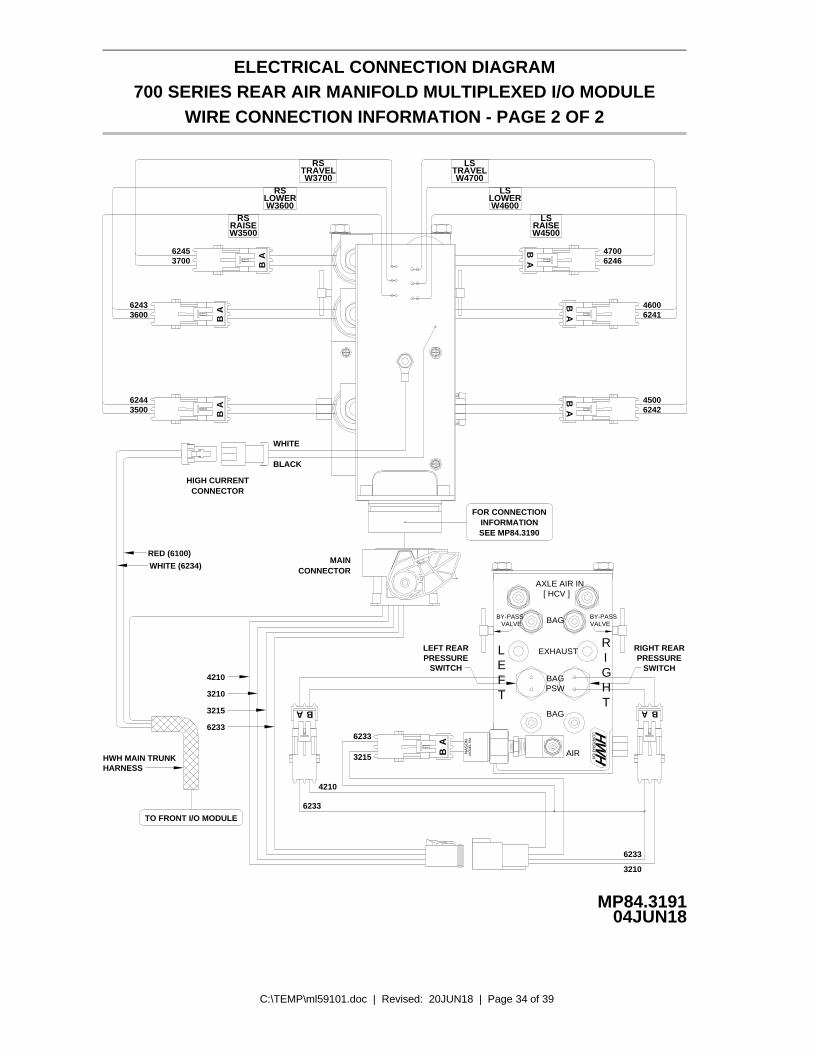
C:\TEMP\ml59101.doc | Revised: 20JUN18 | Page 34 of 39
MP84.3191
ELECTRICAL CONNECTION DIAGRAM700 SERIES REAR AIR MANIFOLD MULTIPLEXED I/O MODULE
04JUN18
WIRE CONNECTION INFORMATION - PAGE 2 OF 2
W3700TRAVEL
RAISEW3500
W3600LOWER
RS
RS
RS
EFT
L
PSWBAG
EXHAUST
R
THG
RI
VALVEBY-PASS
[ HCV ]
BAG
AXLE AIR IN
VALVEBY-PASS
BA
AB
AB
BA
AB
AB
TRAVELW4700
LS
W4600LOWER
LS
LSRAISEW4500
BABA
WHITE
BLACK
SEE MP84.3190INFORMATION
FOR CONNECTION
LEFT REARPRESSURE
SWITCH
RIGHT REARPRESSURE
SWITCH
6233
6233
4210
3210
4210
3210
3215
WHITE (6234)
RED (6100)
AB AIRM
OD
EL
SM
NA
SO
N
BAG
6233
3215
6233
62453700
62433600
62443500
TO FRONT I/O MODULE
HWH MAIN TRUNKHARNESS
62464700
62414600
62424500
CONNECTORMAIN
CONNECTORHIGH CURRENT
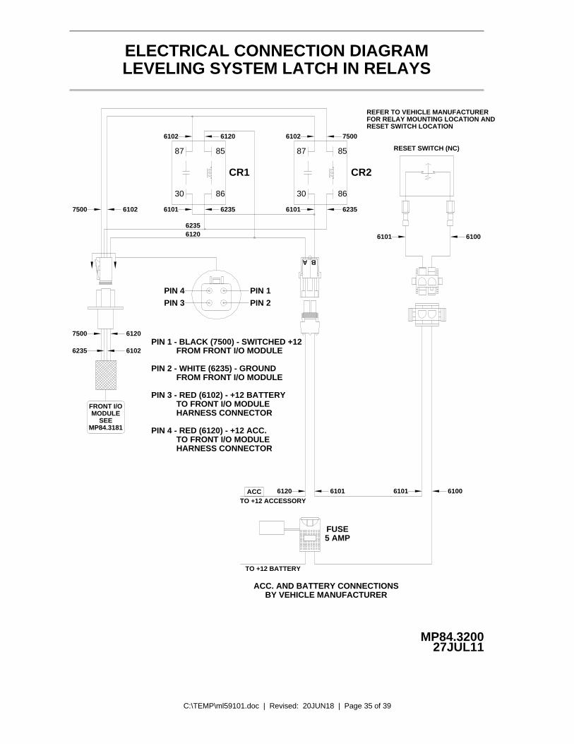
C:\TEMP\ml59101.doc | Revised: 20JUN18 | Page 35 of 39
MP84.320027JUL11
LEVELING SYSTEM LATCH IN RELAYSELECTRICAL CONNECTION DIAGRAM
6120
CR1
62356101
6102
6101 6235
6102 7500
CR2
62356120
61027500
FRONT I/OMODULE
SEEMP84.3181
6120
6102
7500
6235
BA
REFER TO VEHICLE MANUFACTURERFOR RELAY MOUNTING LOCATION ANDRESET SWITCH LOCATION
RESET SWITCH (NC)
61006101
6101 6101 6100
FUSE5 AMP
ACC. AND BATTERY CONNECTIONSBY VEHICLE MANUFACTURER
ACCTO +12 ACCESSORY
TO +12 BATTERY
PIN 4 - RED (6120) - +12 ACC.TO FRONT I/O MODULEHARNESS CONNECTOR
HARNESS CONNECTORTO FRONT I/O MODULE
PIN 3 - RED (6102) - +12 BATTERY
PIN 1 - BLACK (7500) - SWITCHED +12FROM FRONT I/O MODULE
FROM FRONT I/O MODULEPIN 2 - WHITE (6235) - GROUND
PIN 4PIN 3 PIN 2
PIN 1
6120
87 85
8630
8587
30 86

C:\TEMP\ml59101.doc | Revised: 20JUN18 | Page 36 of 39
MP84.343325JUL11
LEVEL SENSING UNITELECTRICAL CONNECTION DIAGRAM
1 2 3654
SEE WIRELEGENDBELOW
SEEELECTRICALCONNECTION
DIAGRAMFRONT AIRMANIFOLD
I/O MODULEMP84.3180
SEE ELECTRICAL CONNECTIONDIAGRAM - HARNESS ROUTING
MOUNTING / ADJUSTMENTSCREWS (3)
A
BD
C
YELLOW LEDS
BOTTOM VIEW OFSENSING UNIT
LED A - FRONT OF VEHICLELED B - LEFT SIDE OF VEHICLE (DRIVER SIDE)LED C - REAR OF VEHICLELED D - RIGHT SIDE OF VEHICLE (PASSENGER SIDE)
WIRE LEGENDPIN 1 - BLACK - 0400 - SWITCHED GROUND WHEN REAR IS LOWPIN 2 - WHITE - 6231 - GROUND FROM SENSING UNITPIN 3 - RED - 6121 - +12 VOLT FOR SENSING UNITPIN 4 - BLACK - 0100 - SWITCHED GROUND WHEN LEFT SIDE IS LOWPIN 5 - BLACK - 0200 - SWITCHED GROUND WHEN FRONT IS LOWPIN 6 - BLACK - 0300 - SWITCHED GROUND WHEN RIGHT SIDE IS LOW

C:\TEMP\ml59101.doc | Revised: 20JUN18 | Page 37 of 39
COMPRESSOR HARNESS FROM
NORMALLY OPEN AIR SOLENOID (1)
COMPRESSOR DIAGRAM
12 VOLT RELAY (2)
AIR FILTER
25JUL11MP84.6085
AIR LINE TO SUSPENSIONCHECK VALVE (3)
GRAY FROM AIR SOLENOID
GROUND
FUSE15 AMP
FLOW
GROUND TO RELAY MOUNTING BOLT
TO +12 BATTERYPOWER - 6100
The control box sends a +12 signal to the normally open12 volt relay. The 12 volt relay (2) will energize and thecompressor will run. The normally open air solenoid (1) will close allowing the compressor to build pressure.
The normally open air solenoid (1) will open any time the compressor is not running, allowing internal pressure & moisture to bleed off. The check valve (3) will keep thesuspension air from bleeding back to the compressor.
ELECTRICAL CONNECTION DIAGRAM
FRONT AIR MANIFOLD I/O MODULE - (BLACK) 9700

C:\TEMP\ml59101.doc | Revised: 20JUN18 | Page 38 of 39
MP84.608625JUL11
BLACK ( GROUND )
RED +12
GROUNDWHITE
(GROUND)
(+12 SIGNAL)
15 AM
P
+12 VOLTBATTERY POWER
NORMALLY OPEN12 VOLT AIR SOLENOID
12 VOLTESSEX RELAY
COMPRESSOR HARNESSFROM FRONT AIR
I/O MODULE+12 SIGNAL - 9700
COMPRESSOR MOTORFUSE15 AMP
(A)
RELAY MTG. BOLT
6100
AIR COMPRESSORELECTRICAL CONNECTION DIAGRAM

C:\TEMP\ml59101.doc | Revised: 20JUN18 | Page 39 of 39
ELECTRICAL CONNECTION DIAGRAM
MP84.619505OCT11
AIR / HYDRAULIC LEVELING SYSTEMTOUCH PANEL CONNECTIONS
LINK LIGHT
GROUND FROM CONTROL MODULECAN SHIELDCAN LOWCAN HIGHYELLOW
GREEN
WIRECOLOR
4321
WHITE
PIN #NUMBER
6230
WIRE WIRE DESCRIPTION AND FUNCTION
PIN 1
SWITCHED BATTERY FROM CONTROL MODULE6800RED5
DO NOT CUTTERMINATING
RESISTOR
NOTE: THERE IS A 120 OHM TERMINATING RESISTOR AT EACHEND OF THE TOUCH PANEL HARNESS. DO NOT REMOVE, CUTOR MODIFY THE HARNESS.
TOUCH PANEL HARNESS
HWH COMPUTERIZED LEVELING
WARNING!UNDERSTAND OPERATOR'S MANUAL BEFORE USING. BLOCK FRAME AND TIRES
SECURELY BEFORE REMOVING TIRES OR CRAWLING UNDER VEHICLE.
EMERGENCYSTOP
MODETRAVEL
LEVEL
MODETRAVEL
RAISE
BRAKEPARK/
SLOPEEXCESS
NOT IN
DUMP
AIR
PIN 4 PIN 1
PIN 6
CN2
PIN 3
6110 7699
CN1
CN1
CN21 - 3 - 4 - 6 NO CONNECTION2 RED 6110 +12 SUPPLY
SWITCHED GROUND WARNING LIGHT CONTROLBLACK5 7699
REVERSEPOLARITY
LED DO NOT
LIGHTWARNINGMASTER