quick start guide -...
TRANSCRIPT

Quick Start Guide

Contents
Page 2
Contents
LEGAL INFORMATION.........................................................................................4
INTRODUCTION....................................................................................................5Conventions used in this documentation............................................................................................................................... 6About this software................................................................................................................................................................. 7About the InduSoft Web Studio software components........................................................................................................ 10Install the full InduSoft Web Studio software.......................................................................................................................15Install the project runtime software on a Windows Embedded device................................................................................ 20Execution Modes.................................................................................................................................................................. 24
THE DEVELOPMENT ENVIRONMENT..............................................................25Title Bar.................................................................................................................................................................................26Status Bar............................................................................................................................................................................. 27Application button................................................................................................................................................................. 28Quick Access Toolbar........................................................................................................................................................... 29Ribbon................................................................................................................................................................................... 31
Home tab....................................................................................................................................................................... 31View tab......................................................................................................................................................................... 31Insert tab........................................................................................................................................................................32Project tab......................................................................................................................................................................33Graphics tab.................................................................................................................................................................. 33Format tab..................................................................................................................................................................... 34Help tab......................................................................................................................................................................... 35
Project Explorer.................................................................................................................................................................... 36Global tab...................................................................................................................................................................... 36Graphics tab.................................................................................................................................................................. 37Tasks tab........................................................................................................................................................................38Comm tab...................................................................................................................................................................... 40
Screen/Worksheet Editor...................................................................................................................................................... 41
ABOUT TAGS AND THE PROJECT DATABASE............................................. 42Understanding the Tag Name Syntax.................................................................................................................................. 44Choosing the Tag Data Type............................................................................................................................................... 45Using Array Tags.................................................................................................................................................................. 46About indirect tags................................................................................................................................................................49
TUTORIAL: BUILDING A SIMPLE PROJECT...................................................50Creating a new project......................................................................................................................................................... 51Specifying the startup screen...............................................................................................................................................53Creating tags.........................................................................................................................................................................54Creating the main screen..................................................................................................................................................... 56
Drawing the main screen's title.....................................................................................................................................58Drawing a button to open another screen.................................................................................................................... 60Saving and closing the main screen.............................................................................................................................62

Contents
Page 3
Creating the synoptic screen................................................................................................................................................63Drawing the synoptic screen's title............................................................................................................................... 63Drawing "Date" and "Time" displays............................................................................................................................. 63Placing an "Exit" icon.................................................................................................................................................... 65Testing the project......................................................................................................................................................... 66Placing an animated tank..............................................................................................................................................66Placing a level slider..................................................................................................................................................... 68Drawing a tank selector................................................................................................................................................ 70Testing the project......................................................................................................................................................... 71
Configuring the communication driver..................................................................................................................................72Monitoring device I/O during runtime............................................................................................................................75
Downloading your project to a Windows Embedded device............................................................................................... 76Deploying your project as a web application....................................................................................................................... 78
Legal Information
Page 4
Legal Information© 2019 AVEVA Group plc and its subsidiaries. All rights reserved.
No part of this documentation shall be reproduced, stored in a retrieval system, or transmitted byany means, electronic, mechanical, photocopying, recording, or otherwise, without the prior writtenpermission of AVEVA. No liability is assumed with respect to the use of the information contained herein.
Although precaution has been taken in the preparation of this documentation, AVEVA assumes noresponsibility for errors or omissions. The information in this documentation is subject to change withoutnotice and does not represent a commitment on the part of AVEVA. The software described in thisdocumentation is furnished under a license agreement. This software may be used or copied only inaccordance with the terms of such license agreement.
ArchestrA, Aquis, Avantis, DYNSIM, eDNA, EYESIM, InBatch, InduSoft, InStep, IntelaTrac, InTouch,PIPEPHASE, PRiSM, PRO/II, PROVISION, ROMeo, SIM4ME, SimCentral, SimSci, Skelta, SmartGlance,Spiral Software, Termis, WindowMaker, WindowViewer, and Wonderware are trademarks of AVEVA and/or its subsidiaries. An extensive listing of AVEVA trademarks can be found at: https://sw.aveva.com/legal. All other brands may be trademarks of their respective owners.
Publication date: January 2019
Introduction
Page 5
IntroductionInduSoft Web Studio (or IWS, for short) is a powerful, integrated tool that exploits key features ofMicrosoft operating systems and enables you to build full-featured SCADA (Supervisory Control and DataAcquisition) or HMI (Human-Machine Interface) programs for your industrial automation business.
This InduSoft Web Studio Quick Start Guide is intended for individuals using IWS for the first time. Thispublication will help you quickly familiarize yourself with the basic functions of IWS.
Introduction
Page 6
Conventions used in this documentationThis documentation uses standardized formatting and terminology to make it easier for all users tounderstand.
Text conventionsThis documentation uses special text formatting to help you quickly identify certain items:
• Titles, labels, new terms, and messages are indicated using italic text (for example, Object Properties).
• File names, screen text, and text you must enter are indicated using monospace text (for example, D:\Setup.exe ).
• Buttons, menu options, and keyboard keys are indicated using a bold typeface (for example, File menu).
In addition, this documentation segregates some text into Tip, Note, and Caution boxes:
• Tips provide useful information to save development time or to improve the project performance.
• Notes provide extra information that may make it easier to understand the nearby text, usually thetext just before the note.
• Cautions provide information necessary to prevent errors that can cause problems when running theproject, and may result in damage.
Mouse and selection conventionsBecause most PCs used for project development run a version of Microsoft Windows with a mouse, thisdocumentation assumes you are using a mouse. Generally, a PC mouse is configured for right-handeduse, so that the left mouse button is the primary button and the right mouse button is the secondarybutton.
This documentation uses the following mouse and selection conventions:
• Click and Select both mean to click once on an item with the left mouse button. In general, you clickbuttons and you select from menus and lists.
• Double-click means to quickly click twice on an item with the left mouse button.
• Right-click means to click once on an item with the right mouse button.
• Select also means you should use your pointing device to highlight or specify an item on the computerscreen. Selecting an item with a touchscreen is usually the same as selecting with a mouse, exceptthat you use your finger to touch (select) a screen object or section. To select items with your keyboard,you typically use the Tab key to move around options, the Enter key to open menus, and the Alt keywith a letter key to select an object that has an underlined letter.
• Drag means to press down the appropriate mouse button and move the mouse before releasing thebutton. Usually an outline of the item will move with the mouse cursor.
Windows conventionsThis documentation uses the following Windows conventions:
• Dialogs are windows that allow you to configure settings and enter information.
• Text boxes are areas in dialogs where you can type text.
• Radio buttons are white circles in which a black dot appears or disappears when you click on thebutton. Typically, the dot indicates the option is selected or enabled. No dot indicates the option iscleared or disabled.
• Check boxes are white squares in which a check ( ) appears or disappears when you click on itwith the cursor. Typically, a check indicates the option is selected or enabled. No check indicatesthe option is cleared or disabled.
• Buttons are icons in boxes appear "pressed" when you click on them.
• Lists are panes (white boxes) in windows or dialogs containing two or more selectable options.
• Combo boxes have arrows that, when clicked, show part or all of an otherwise concealed list.
• Dockable windows are windows that you can drag to an edge of the interface and merge with thatedge.
Introduction
Page 7
About this softwareInduSoft Web Studio (or IWS, for short) is powerful software for developing HMI, SCADA, and OEE/Dashboard projects that can be deployed anywhere.
Each IWS project consists of:
• A project tags database to manage all run-time data, including both internal variables and I/O data;
• Configurable drivers to communicate in real-time with programmable logic controllers (PLCs), remoteI/O devices, and other data-acquisition equipment;
• Animated human-machine interface (HMI) screens and overall equipment effectiveness (OEE)dashboards; and
• Optional modules such as alarms, events, trends, recipes, reports, scriptable logic, schedulers, aproject security system, and a complete database interface.
After you develop your project, you can either run it locally on your development workstation or downloadit to a remote computer and run it there. The project runtime server processes I/O data from connecteddevices according to your project parameters and then reacts to, displays, and/or saves the data.
Product featuresActiveX and .NET
Use third-party controls to enhance your project. This software is a container for ActiveXand .NET controls. Add functionality such as browsers, media players, charting, and othertools that support the ActiveX and .NET interface standards.
AlarmsIn addition to all of the alarm functions you would expect, this software also sends alarmsusing multi-media formats like PDF. Use remote notification to have alarms sent right toyour email inbox, a printer, or a smartphone! Alarms are real-time and historical, log data inbinary format or to any database.
AnimationThis software gives you great command over graphics. Paste images, and even rotatethem dynamically. Fill bar graphs with color, or adjust the scale of objects with easy-to-use configuration. Other animations include "command" (for touch, keyboard and mouseinteraction), hyperlink, text data link, color, resize (independent height and width), position,and rotation (with custom rotation point).
DatabaseConnect to SQL databases (MS SQL, MySQL, Sybase, Oracle), MS Access and Excel, andERP/MES systems (including SAP), even from Windows Embedded. Flexible enough to havea built-in interface without the need to know SQL (for trends, alarms/events, grid and otherobjects), or use any SQL statement you need anywhere you need it.
DriversThis software includes over 240 built-in communication drivers for most PLCs, temperaturecontrollers, motion controllers, barcode/RFID readers, and other devices. Use these built-indrivers without the need for OPC servers (but are an optional connection method).
EmailSend email via SMTP to any desktop or mobile device. Get real-time information on alarms,process values, and other events. This software supports SSL encryption allowing the use ofthird-party providers such as Gmail.
EventsThis software offers traceability for operator initiated actions or internal system activity. Logevents such as security system changes (user logon or off), screen open/close, recipe/reportoperations, custom messages and system warnings. Also any tag value changes includingcustom messages.
FDA Traceability

Introduction
Page 8
Take advantage of built-in traceability and e-signature features to create projects that fullycomply with U.S. Food and Drug Administration regulations (Title 21 CFR Part 11). Thesefeatures are often used in food and pharmaceutical applications, but they can be used inany application where traceability is required.
FTPAutomatically upload or download files during run time to/from remote storage locationsusing FTP and flexible scripting functions. Configure FTP via scripting or the includedconfiguration interface.
Graphics and Design ToolsCreate powerful screens to meet any application need using the improved tools in ourgraphic interface. Combine built-in objects to create any functionality required. Storegraphics in the symbol library for future use. Easily make projects across a product lineshare a consistent "look and feel".
Historical PerformanceWe have optimized the trend history module and designed it to load millions of values fromSQL relational databases with high performance, with built-in data decimation in the TrendControl. Easy-to-use tools provide quick access to Statistical Process Control (SPC) valueswithout any need for programming.
Intellectual Property ProtectionScreens, documents, scripts and even math worksheets can be individually passwordprotected. This prevents unauthorized viewing or editing of your corporate customfunctionality. Protect the entire project with just a few mouse clicks.
Multi-LanguageDevelop your project in one of many development languages, including English, Portuguese,German, and French.
OPCAs an alternative to the built-in drivers for direct communication with PLCs, you can alsouse any of several different versions of OLE for Process Control (OPC) to manage yourdevices. This software includes support for "classic" OPC DA (client or server), OPC UA(client or server), OPC XML-DA (client only), and OPC HDA (server only).
PDF ExportSend Alarms, Reports, or any file (including .doc or .txt) to a production supervisor, qualitymanager, or maintenance staff using the included PDF writer.
RecipesSave time and maintain consistency by automating part parameters or productionsquantities with any triggering event.
RedundancyFor critical applications where data is vital, this software supports web server, database andoverall system redundancy.
ReportsCreate clear, concise reports in text format, graphical RTF, XML, PDF, HTML, and CSV, orintegrate with Microsoft Office. Get the data you need, in the format you need it, to makeinformed decisions, fast.
ScalableDevelop once and deploy anywhere, on any currently supported version of MicrosoftWindows.
SchedulerSchedule custom tag changes on date/time, frequency, or any trigger. Use this forsimulation, to trigger reports or other functionality at a particular time of day, or even totrigger driver worksheets to read/write at a scan rate you choose.
Introduction
Page 9
ScriptingTwo powerful scripting languages are supported. Use built-in functions or use standardVBScript to take advantage of widely available resources. Both can be used simultaneouslyto give you the functionality you need.
SecurityThis software provides support for group and user accounts, e-signatures, and traceability,as well as support for Lightweight Directory Access Protocol (LDAP). Integrate your projectwith your Active Directory, including Active Directory Application Mode (ADAM).
SSL Support for EmailsNative support for Secure Socket Layer (SSL), which makes it easy and secure to sendemails from this software using third-party tools such as Gmail!
StandardsTake advantage of common industry standards to develop projects that are compatible withany format. TCP/IP, ActiveX/.NET, OPC (client and server), COM/DCOM, OLE, XML, SOAP,and HTML are all supported.
SNMPEasily configure managed networked devices on IP networks (such as switches and routers)using incorporated SNMP configuration commands and an easy-to-use configurationinterface.
SymbolsAn extensive library of pre-made symbols features push buttons, pilot lights, tanks, sliders,meters, motors, pipes, valves and other common objects. Use the included symbols in yourproject, modify existing symbols to suit your needs, or create your own from scratch. Plussupport for third-party symbol libraries and graphic tools.
Tags DatabaseThis software features an object-oriented tags database with boolean, integer, real, strings,arrays, classes (structures), indirect tags, and included system tags.
Thin ClientsRemotely view project screens on several different types of thin clients. Use the standaloneSecure Viewer to acheive the greatest security on plant-floor stations. Use the InternetExplorer-based Web Thin Client to achieve the greatest flexibility on Windows desktops.Or use the HTML5-enabled Mobile Access to access your project from almost any othercomputer or mobile device.
TrendsReal-time and Historical trends are supported. Log data in binary format or to any databaselocally and remotely. Color or fill trends with graphic elements to enhance clarity of data.Date/Time based or numeric (X/Y plot) trends give you the flexibility to display informationthat best suits your project.
TroubleshootingQuickly debug and verify a project using local and remote tools for troubleshooting,including status fields, Database Spy and LogWin. Capture screen open and close times,see communications in real-time, and messages related to OPC, recipes/reports, security,database errors and even custom messages. Quickly get your project finished using thesepowerful tools.
Introduction
Page 10
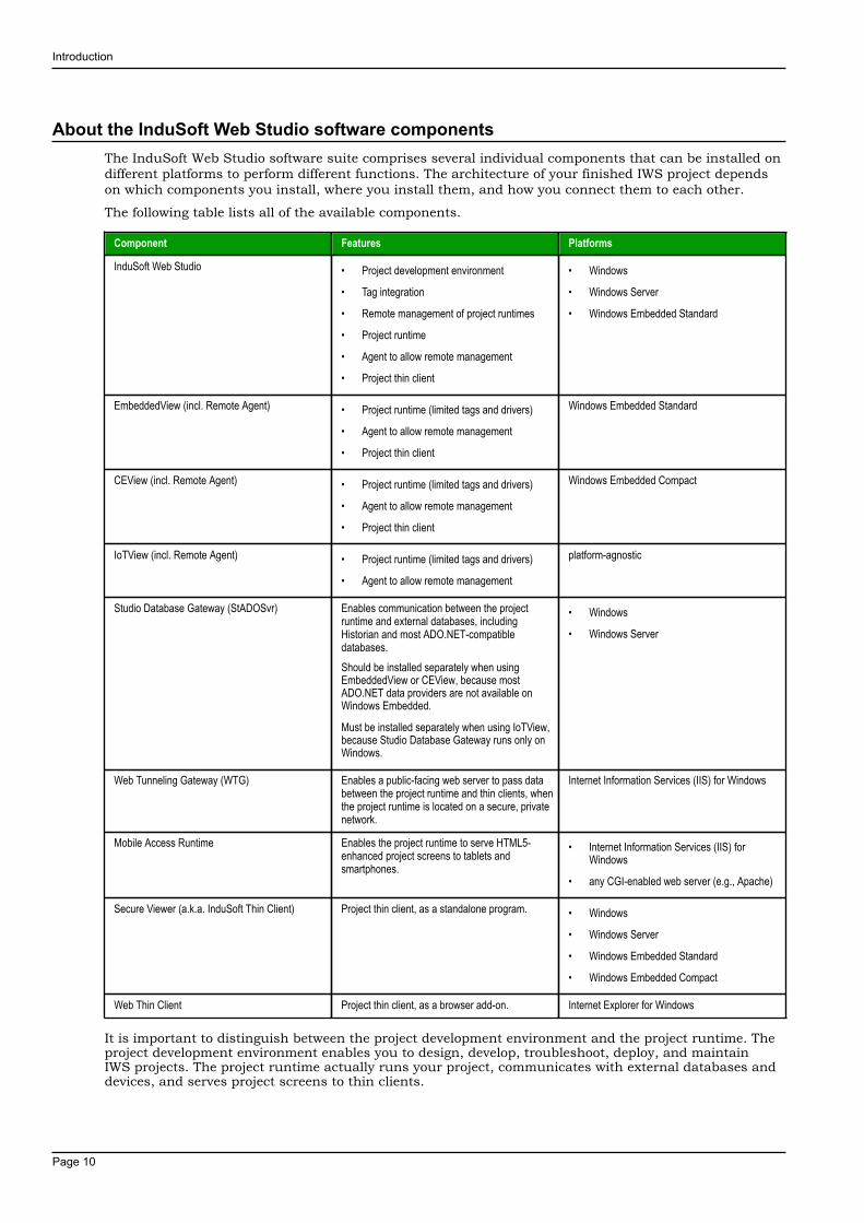
About the InduSoft Web Studio software componentsThe InduSoft Web Studio software suite comprises several individual components that can be installed ondifferent platforms to perform different functions. The architecture of your finished IWS project dependson which components you install, where you install them, and how you connect them to each other.
The following table lists all of the available components.
Component Features Platforms
InduSoft Web Studio • Project development environment
• Tag integration
• Remote management of project runtimes
• Project runtime
• Agent to allow remote management
• Project thin client
• Windows
• Windows Server
• Windows Embedded Standard
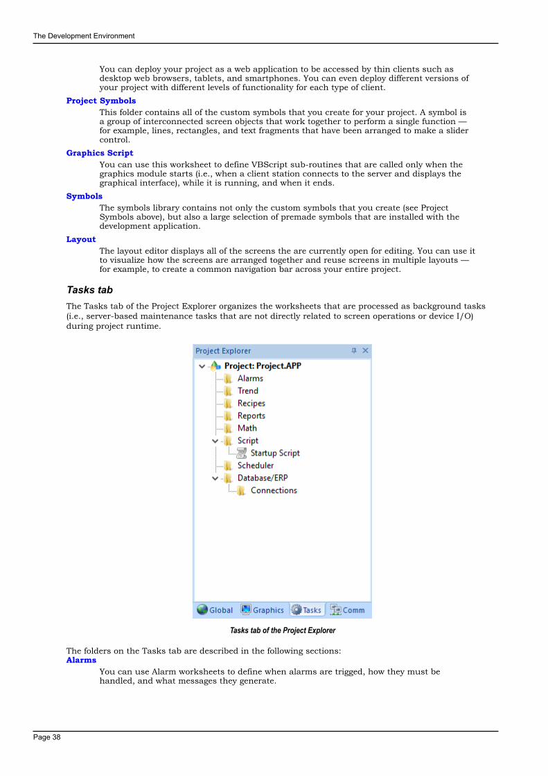
EmbeddedView (incl. Remote Agent) • Project runtime (limited tags and drivers)
• Agent to allow remote management
• Project thin client
Windows Embedded Standard
CEView (incl. Remote Agent) • Project runtime (limited tags and drivers)
• Agent to allow remote management
• Project thin client
Windows Embedded Compact
IoTView (incl. Remote Agent) • Project runtime (limited tags and drivers)
• Agent to allow remote management
platform-agnostic
Studio Database Gateway (StADOSvr) Enables communication between the projectruntime and external databases, includingHistorian and most ADO.NET-compatibledatabases.Should be installed separately when usingEmbeddedView or CEView, because mostADO.NET data providers are not available onWindows Embedded.
Must be installed separately when using IoTView,because Studio Database Gateway runs only onWindows.
• Windows
• Windows Server
Web Tunneling Gateway (WTG) Enables a public-facing web server to pass databetween the project runtime and thin clients, whenthe project runtime is located on a secure, privatenetwork.
Internet Information Services (IIS) for Windows
Mobile Access Runtime Enables the project runtime to serve HTML5-enhanced project screens to tablets andsmartphones.
• Internet Information Services (IIS) forWindows
• any CGI-enabled web server (e.g., Apache)
Secure Viewer (a.k.a. InduSoft Thin Client) Project thin client, as a standalone program. • Windows
• Windows Server
• Windows Embedded Standard
• Windows Embedded Compact
Web Thin Client Project thin client, as a browser add-on. Internet Explorer for Windows
It is important to distinguish between the project development environment and the project runtime. Theproject development environment enables you to design, develop, troubleshoot, deploy, and maintainIWS projects. The project runtime actually runs your project, communicates with external databases anddevices, and serves project screens to thin clients.
Introduction
Page 11
The full InduSoft Web Studio software includes both the project development environment and the projectruntime. Your software license determines which parts of the software you can use. For more information,see Execution Modes on page 24.
In contrast, EmbeddedView and CEView are runtime-only components for Windows Embedded Standardand Windows Embedded Compact, respectively, and IoTView is a new, platform-agnostic runtime for otheroperating systems. They cannot be used for project development, so they have lower system requirementsthan the full InduSoft Web Studio software.
In most cases, the first thing you should do is install the full InduSoft Web Studio software on yourprimary workstation, because it not only sets up the project development environment for you, it alsounpacks the rest of the components so that they can be installed on other computers and devices.
Tip: Separate installers for some components can be found on the InduSoft Web Studioinstallation media or downloaded from our website (www.indusoft.com).
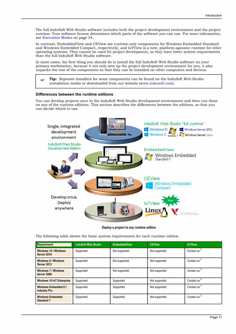
Differences between the runtime editionsYou can develop projects once in the InduSoft Web Studio development environment and then run themon any of the runtime editions. This section describes the differences between the editions, so that youcan decide which to use.
Deploy a project to any runtime edition
The following table shows the basic system requirements for each runtime edition.
Requirement InduSoft Web Studio EmbeddedView CEView IoTView
Windows 10 / WindowsServer 2016
Supported Not supported Not supported Contact us 2
Windows 8 / WindowsServer 2012
Supported Not supported Not supported Contact us 2
Windows 7 / WindowsServer 2008
Supported Not supported Not supported Contact us 2
Windows 10 IoT Enterprise Supported Supported Not supported Contact us 2
Windows Embedded 8.1Industry Pro
Supported Supported Not supported Contact us 2
Windows EmbeddedStandard 7
Supported Supported Not supported Contact us 2

Introduction
Page 12
Requirement InduSoft Web Studio EmbeddedView CEView IoTView
Windows EmbeddedCompact 2013
Not supported Not supported Supported Contact us 2
Windows EmbeddedCompact 7
Not supported Not supported Supported Contact us 2
Windows EmbeddedCompact 6 1
Not supported Not supported Supported Contact us 2
Linux (Debian-baseddistributions)
Not supported Not supported Not supported Supported
Wind River VxWorks Not supported Not supported Not supported Supported
Available storage (harddrive or non-volatile)
2 GB 128 MB 64 MB 64 MB
Available memory (RAM) 1 GB 64 MB 32 MB 32 MB
1. Windows Embedded Compact 6 was formerly known as Windows CE 6.
2. IoTView is a platform-agnostic runtime edition, which means it can run on many different devicesand operating systems. Only Linux and VxWorks are listed as "Supported" because those are the onlyoperating systems for which we have compiled and fully validated IoTView. If you want to run IoTViewon another device or operating system, contact your InduSoft Web Studio software distributor.
For a complete list of system requirements for each runtime edition, see the installation instructions forthat edition.
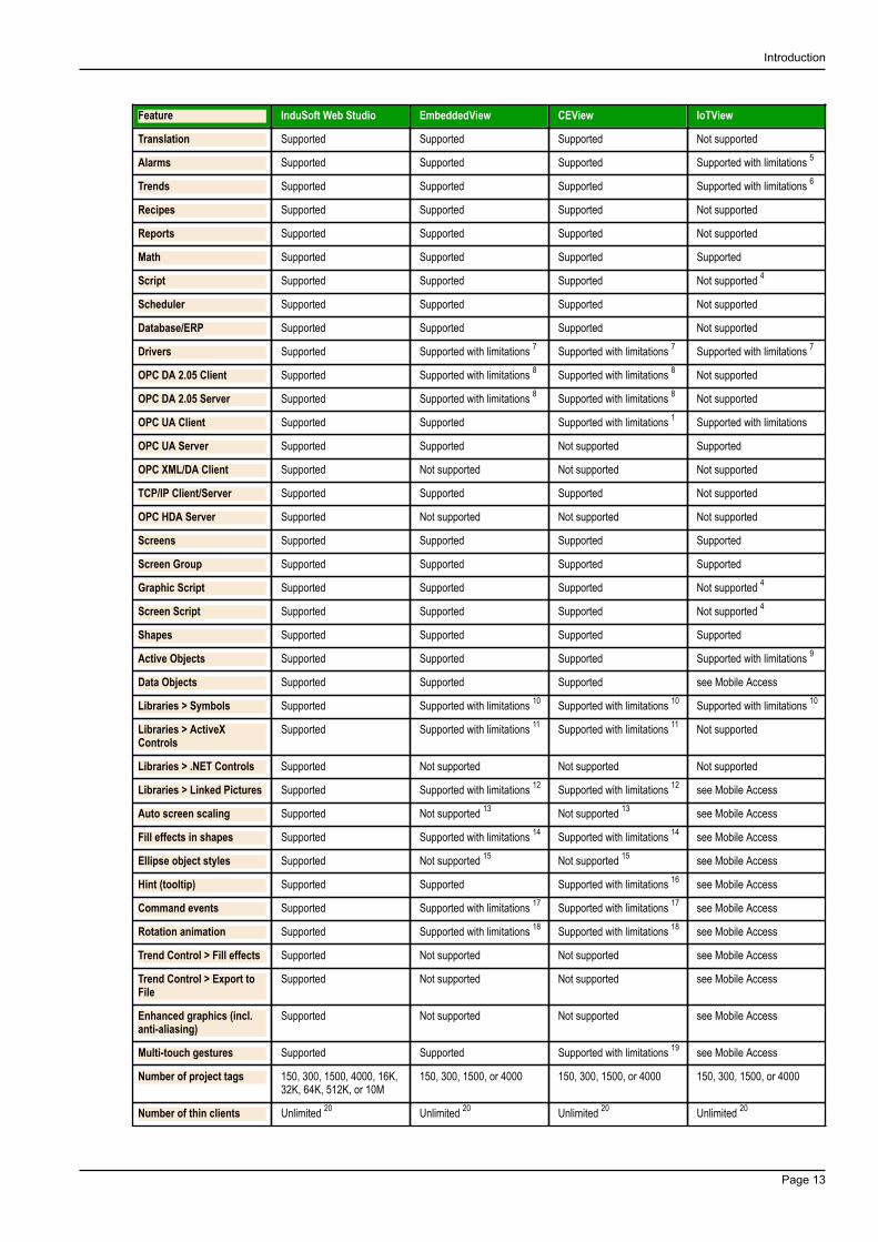
The following table shows the main differences in support for project features between the runtimeeditions. (The majority of features are fully supported in all editions, so they are not listed.) If you developa project to include features that are not supported in your chosen edition, you might see unexpectedbehavior and possibly even serious errors during run time. Some features will be automatically blocked inthe project development environment when you select your project's target platform, but you should stillbe aware of the differences. For more information, see About target platforms, product types, and targetsystems.
Feature InduSoft Web Studio EmbeddedView CEView IoTView
Run projects developed inInduSoft Web Studio
Supported Supported Supported Supported
Run as a Windows service Supported Not supported Not supported Not supported
Local project viewer Supported Supported Supported Not supported
Server for Secure Viewer Supported Supported Supported Not supported
Server for Web Thin Client Supported Supported Supported Not supported
Support for Mobile Access Supported Supported Not supported Supported
Support for Mobile AccessTabular
Supported Supported Supported Not supported
Email (SMTP client) Supported Supported Supported with limitations 1 Not supported
Create tagsprogrammatically duringrun time
Supported Not supported Not supported Not supported
Create screensprogrammatically duringrun time
Supported Not supported Not supported Not supported
Save reports in PDF format Supported Not supported Not supported Not supported
Built-in functions Supported Supported with limitations 2 Supported with limitations 2 Supported with limitations 2
Tag integration (a.k.a.Shared Tags)
Supported Supported Supported Not supported
Security Supported Supported Supported Supported with limitations 3
Procedures Supported Supported Supported Not supported 4
Event Logger Supported Supported Supported Not supported
Introduction
Page 13
Feature InduSoft Web Studio EmbeddedView CEView IoTView
Translation Supported Supported Supported Not supported
Alarms Supported Supported Supported Supported with limitations 5
Trends Supported Supported Supported Supported with limitations 6
Recipes Supported Supported Supported Not supported
Reports Supported Supported Supported Not supported
Math Supported Supported Supported Supported
Script Supported Supported Supported Not supported 4
Scheduler Supported Supported Supported Not supported
Database/ERP Supported Supported Supported Not supported
Drivers Supported Supported with limitations 7 Supported with limitations 7 Supported with limitations 7
OPC DA 2.05 Client Supported Supported with limitations 8 Supported with limitations 8 Not supported
OPC DA 2.05 Server Supported Supported with limitations 8 Supported with limitations 8 Not supported
OPC UA Client Supported Supported Supported with limitations 1 Supported with limitations
OPC UA Server Supported Supported Not supported Supported
OPC XML/DA Client Supported Not supported Not supported Not supported
TCP/IP Client/Server Supported Supported Supported Not supported
OPC HDA Server Supported Not supported Not supported Not supported
Screens Supported Supported Supported Supported
Screen Group Supported Supported Supported Supported
Graphic Script Supported Supported Supported Not supported 4
Screen Script Supported Supported Supported Not supported 4
Shapes Supported Supported Supported Supported
Active Objects Supported Supported Supported Supported with limitations 9
Data Objects Supported Supported Supported see Mobile Access
Libraries > Symbols Supported Supported with limitations 10 Supported with limitations 10 Supported with limitations 10
Libraries > ActiveXControls
Supported Supported with limitations 11 Supported with limitations 11 Not supported
Libraries > .NET Controls Supported Not supported Not supported Not supported
Libraries > Linked Pictures Supported Supported with limitations 12 Supported with limitations 12 see Mobile Access
Auto screen scaling Supported Not supported 13 Not supported 13 see Mobile Access
Fill effects in shapes Supported Supported with limitations 14 Supported with limitations 14 see Mobile Access
Ellipse object styles Supported Not supported 15 Not supported 15 see Mobile Access
Hint (tooltip) Supported Supported Supported with limitations 16 see Mobile Access
Command events Supported Supported with limitations 17 Supported with limitations 17 see Mobile Access
Rotation animation Supported Supported with limitations 18 Supported with limitations 18 see Mobile Access
Trend Control > Fill effects Supported Not supported Not supported see Mobile Access
Trend Control > Export toFile
Supported Not supported Not supported see Mobile Access
Enhanced graphics (incl.anti-aliasing)
Supported Not supported Not supported see Mobile Access
Multi-touch gestures Supported Supported Supported with limitations 19 see Mobile Access
Number of project tags 150, 300, 1500, 4000, 16K,32K, 64K, 512K, or 10M
150, 300, 1500, or 4000 150, 300, 1500, or 4000 150, 300, 1500, or 4000
Number of thin clients Unlimited 20 Unlimited 20 Unlimited 20 Unlimited 20
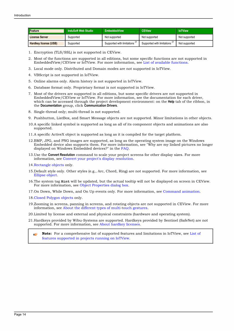
Introduction
Page 14
Feature InduSoft Web Studio EmbeddedView CEView IoTView
License Server Supported Not supported Not supported Not supported
Hardkey license (USB) Supported Supported with limitations 21 Supported with limitations 21 Not supported
1. Encryption (TLS/SSL) is not supported in CEView.
2. Most of the functions are supported in all editions, but some specific functions are not supported inEmbeddedView/CEView or IoTView. For more information, see List of available functions.
3. Local mode only. Distributed and Domain modes are not supported in IoTView.
4. VBScript is not supported in IoTView.
5. Online alarms only. Alarm history is not supported in IoTView.
6. Database format only. Proprietary format is not supported in IoTView.
7. Most of the drivers are supported in all editions, but some specific drivers are not supported inEmbeddedView/CEView or IoTView. For more information, see the documentation for each driver,which can be accessed through the project development environment: on the Help tab of the ribbon, inthe Documentation group, click Communication Drivers.
8. Single-thread only; multi-thread is not supported.
9. Pushbutton, ListBox, and Smart Message objects are not supported. Minor limitations in other objects.
10.A specific linked symbol is supported as long as all of its component objects and animations are alsosupported.
11.A specific ActiveX object is supported as long as it is compiled for the target platform.
12.BMP, JPG, and PNG images are supported, as long as the operating system image on the WindowsEmbedded device also supports them. For more information, see "Why are my linked pictures no longerdisplayed on Windows Embedded devices?" in the FAQ.
13.Use the Convert Resolution command to scale your project screens for other display sizes. For moreinformation, see Convert your project's display resolution.
14.Rectangle objects only.
15.Default style only. Other styles (e.g., Arc, Chord, Ring) are not supported. For more information, seeEllipse object.
16.The system tag Hint will be updated, but the actual tooltip will not be displayed on screen in CEView.For more information, see Object Properties dialog box.
17.On Down, While Down, and On Up events only. For more information, see Command animation.
18.Closed Polygon objects only.
19.Zooming in screens, panning in screens, and rotating objects are not supported in CEView. For moreinformation, see About the different types of multi-touch gestures.
20.Limited by license and external and physical constraints (hardware and operating system).
21.Hardkeys provided by Wibu-Systems are supported. Hardkeys provided by Sentinel (SafeNet) are notsupported. For more information, see About hardkey licenses.
Note: For a comprehensive list of supported features and limitations in IoTView, see List offeatures supported in projects running on IoTView.
Introduction
Page 15
Install the full InduSoft Web Studio softwareInstall the full InduSoft Web Studio software on your Windows computer in order to develop IWS projects,or to use the computer as a project runtime server and/or thin client.
To install and run the full InduSoft Web Studio software, you must have the following:
• A Windows-compatible computer with a standard keyboard, a pointer input (i.e., a mouse, trackpad, ortouchscreen), and an SVGA-minimum display;
• One of the following Windows operating systems:
• Windows Server 2016
• Windows Server 2012 R2
• Windows Server 2008 R2 Service Pack 1
• Windows 10 (including LTSC/LTSB versions)
• Windows 8.1
• Windows 7 Service Pack 1
• Windows 10 IoT Enterprise (LTSC/LTSB version only)
• Windows Embedded 8.1 Industry Pro (formerly known as Windows Embedded Standard 8)
• Windows Embedded Standard 7 Service Pack 1
• .NET Framework 3.5 and .NET Framework 4.7 (see note below);
• Internet Explorer 11 or later (not Microsoft Edge);
• 2 GB free storage (hard drive or non-volatile);
• 1 GB free memory (RAM); and
• An Ethernet or Wi-Fi network adapter.
We recommend the "Pro" and "Enterprise" editions of Windows, because they include Internet InformationServices (IIS) as a pre-installed feature that can be turned on. You can use IIS to make your projectsaccessible to thin clients and mobile devices. We do not recommend the "Home" and "Education" editionsof Windows, because they hide or disable many important features.
Only Windows 10 and Windows Server 2016 are under what Microsoft calls "mainstream support",which means they are actively maintained and additional service packs might be released for them inthe future. Windows 8.1, Windows 7, Windows Server 2012 R2, and Windows Server 2008 R2 are underwhat Microsoft calls "extended support", which means they are no longer actively maintained. For moreinformation, go to: support.microsoft.com/en-us/help/13853/windows-lifecycle-fact-sheet
You can install the full InduSoft Web Studio software on a Windows IoT or Windows Embedded device,as long as it meets the system requirements listed above, but if you do not plan to develop projects onthat device then you should install EmbeddedView instead. For more information, see Install the projectruntime software on a Windows Embedded device on page 20.
Regardless of which version or edition of Windows you are using, you should make sure it is fully updatedbefore you install InduSoft Web Studio. Updating Windows ensures that it has all of the latest securityfixes and system components.
Note:
You must have both .NET Framework 3.5 and .NET Framework 4.7 installed and turned on inorder to use all of the features of InduSoft Web Studio.
If Windows is fully updated, as described above, then the latest versions of .NET Frameworkshould be installed. They might not be turned on, however, so use the Windows Features controlpanel to confirm that they are.
In some cases, it might not be possible to keep Windows fully updated through normal means.(For example, if your computer is on a secure network, then it might not be able to contactthe Windows Update service.) The InduSoft Web Studio software installer will check for bothversions of .NET Framework, and if it does not find them, it will attempt to install them for you.Depending on your computer's security settings, however, the installation(s) might fail withoutnotice. Therefore, if you experience issues later while trying to use InduSoft Web Studio — inparticular, while trying to communicate with external databases — use the Windows Featurescontrol panel to confirm that both versions of .NET Framework are installed and turned on.
Introduction
Page 16
In Windows Server 2012 R2, .NET Framework 3.5 is not pre-installed and it cannot be installedby the InduSoft Web Studio software installer. You must use the Server Manager tool to install it.For more information, see Install .NET Framework 3.5 in Windows Server 2012 R2.
For more information about .NET Framework, go to: docs.microsoft.com/en-us/dotnet/framework/index
The following items are optional but recommended:
• A USB port, to install the software from a USB flash drive.
This is optional because you can also download the installer over the network to your computer.
• A USB port or memory card slot, to be used for hardkey licensing of the software.
This is optional because softkey licensing is also available.
• Serial COM ports and adapters, to be used for direct communication with PLCs and other devices.
This is optional because many newer device protocols use TCP/IP or UDP/IP communication (i.e.,Ethernet) instead of serial communication.
• Internet Information Services (IIS) installed and turned on; for more information, see the description ofthe Mobile Access Runtime option below.
This is optional because you may choose not to install the Mobile Access Runtime feature at this time,as part of the full InduSoft Web Studio software. You can install it at a later time, for either IIS or CGI.
• Visual Studio 2010 or Team Explorer 2010 installed on the same computer; for more information, seethe description of the Collaboration option below.
This is optional because you may choose not to install the Collaboration feature.
Finally, you must have Administrator privileges on the computer in order to install any software.
To install the full InduSoft Web Studio software:
1. Close all other running programs, if possible.We recommend you do this because those programs can use a significant amount of system resourcesand therefore cause this installation to take longer to finish. Windows services (e.g., WindowsDefender, Windows Update) can have the same effect, but we do not recommend you stop or disablethose services.
2. Do one of the following:
• Download the zipped installer to your computer, either from our website (www.indusoft.com) orfrom another location on your network where you have previously saved it. Extract the files, openthe resulting folder, and then locate and run the setup program (setup.exe).
• Insert the installation drive into your USB port. If it does not autorun, locate and open the Welcomepage (InduSoft.htm). When the page is opened in your browser, click Product Installation and thenfollow the instructions.
The installation wizard runs and asks you to select a language for the installation.
3. Select a language from the list, and then click OK.This selection determines the language of the user interface for both the installation wizard andthe project development environment. You can change the language for the project developmentenvironment later, after the software has been installed.The wizard prepares for installation. During this step, it automatically installs SafeNet's Sentineldrivers (a part of the software licensing mechanism), .NET Framework 3.5, and .NET Framework 4.7, ifnecessary.
4. On the Welcome page of the wizard, click Next to proceed with the installation.
5. On the License Agreement page, click Yes to accept the agreement and proceed, or click No to refuse theagreement and exit the wizard.
6. On the Customer Information page, type your user name and company name, and then click Next.7. On the Choose Destination Location page, select the folder where the software should be installed, and then
click Next.By default, the software will be installed at the following location:
C:\Program Files (x86)\InduSoft Web Studio v8.1\

Introduction
Page 17
8. On the Select Features page, select the specific features and components that you want to install, andthen click Next.Feature Description
Program Files The main program files for the projectdevelopment application, the project runtimeserver, and the project runtime client. Thisfeature cannot be deselected.
Demos Premade projects that demonstrate thecapabilities of the InduSoft Web Studio software.
Hardkey Support Additional drivers to support the use of hardkeylicenses.
OPC Components Additional components required forcommunication with other OPC-compatibledevices. This includes OPC DA (a.k.a. OPCClassic), OPC XML-DA, and OPC UA.
PDF Printing Additional software that allows run-time reportsto be saved as PDF files.
Security System Device Driver An additional keyboard driver that enforcesproject security during run time by controllinguser input.
Symbol Library A library of premade but configurable screenobjects such as pushbuttons, toggle switches,gauges, dials, indicator lights, and so on.
Runtime for Windows Embedded Compact Also called CEView, the project runtime software(server/client, but not development) for WindowsEmbedded Compact on selected processors.Check the documentation for your specific deviceto see which processor it uses.
Selecting this feature will not actually installCEView on your computer at this time. It willsimply unpack the installation files and copythem to your program folder, so that you caninstall CEView on a Windows Embedded Compactdevice at a later time.
Runtime for Windows Embedded Standard Also called EmbeddedView, the project runtimesoftware (server/client, but not development) forWindows Embedded Standard computers.
Selecting this feature will not actually installEmbeddedView on your computer at this time.It will simply unpack the installation files andcopy them to your program folder, so that you caninstall EmbeddedView on a Windows EmbeddedStandard computer at a later time.
Mobile Access Runtime Add-on software for web servers that allowsmobile devices (i.e., smartphones and tablets) toaccess your projects. This software is available forboth Internet Information Services (IIS) and other,CGI-based web servers like Apache.
You do not need to install this featureat this time. Regardless of whether youselect this installation option, a separateMobile Access Runtime software installer(MobileAccessSetup.exe) will be unpacked withthe rest of the InduSoft Web Studio software, andyou can choose to run that installer at a latertime.
To use this feature, your software license mustinclude the Mobile Access Runtime add-on. To

Introduction
Page 18
Feature Descriptionpurchase this add-on, contact your InduSoft WebStudio software distributor.
Collaboration Tools Additional tools for workgroup collaboration andsource control within the InduSoft Web Studioproject development environment.
This feature requires that you have Visual StudioTeam Explorer 2010 installed on the samecomputer. The InduSoft Web Studio softwareinstaller will attempt to verify that you do, andif you do not, it will not install this feature.To download Team Explorer 2010 for free,go to: www.microsoft.com/en-us/download/details.aspx?id=329
The full version of Visual Studio 2010 includesthe Team Explorer module.
Note: Team Explorer 2012, TeamExplorer 2013, and Team Explorer2017 are not supported as collaborationclients at this time.
You should also have Visual Studio TeamFoundation Server 2010 or 2012 runningsomewhere on your network, but if you donot, it will not prevent you from installing theCollaboration feature at this time.
Note: Team Foundation Server 2013and Team Foundation Server 2017 arenot supported as collaboration serversat this time.
To use this feature, your software license mustinclude the Collaboration add-on. To purchasethis add-on, contact your InduSoft Web Studiosoftware distributor.
IoTView The project runtime software for Linux andVxWorks.
Selecting this feature will not actually installIoTView on your computer at this time. It willsimply unpack the installation files and copythem to your program folder, so that you caninstall IoTView on another computer at a latertime.
Historian Additional software that is required to savehistorical data (e.g., from Trend worksheets) toHistorian databases and AVEVA Insight.
This feature requires that you have .NETFramework 4.7.2 installed and turned on.
Custom Widget Framework Additional software that is required to developHTML5-based widgets and then use them inproject screens.
OPC Factory Server A standalone OPC server that your projects canuse to communicate with Schneider Electric PLCs(e.g., M340, M580, Quantum, TSX Compact,TSX Micro, TSX Momentum, TSX Series 7, TSXS1000, TSX/PCX Premium, Unity Momentum).For more information, see the documentation thatis installed with OPC Factory Server.
Introduction
Page 19
9. On the Ready To Install page, click Install.
Note: You might receive the following error message during installation: "Error 1628: Failedto complete script based install." For more information about this error and how to resolve it,go to: flexeracommunity.force.com/customer/articles/en_US/ERRDOC/Error-1628-Failed-To-Complete-Script-Based-Install
Note: If you try to install an earlier version of the InduSoft Web Studio software on acomputer that already has a later version installed, you might receive the following messageduring installation: "Version x.x.x.x of CodeMeter Development Kit is already installed.Downgrading to Version x.x.x.x is not possible, installation will be aborted." CodeMeter issupplemental software used by InduSoft Web Studio to manage hardkey licenses. To resolvethis issue, you must use Task Manager in Windows to stop CodeMeter Runtime Server(CodeMeter.exe) before you install the earlier version of InduSoft Web Studio.
The software is installed, and then when the installation is finished, the last page of the wizard isdisplayed.
10.Click Finish to close the installation wizard.
When you have finished the installation, you can find the software in your Windows Start menu at: Start >InduSoft Web Studio v8.1
Note:
In Windows 8 / Windows Server 2012, the software should be located at: Start > Apps > InduSoftWeb Studio v8.1
In Windows 7 / Windows Server 2008, the software should be located at: Start > All Programs >InduSoft Web Studio v8.1
The software includes the following "apps" (applications):
IWS v8.1 InduSoft Web StudioThe project development environment, project runtime server, and project thin client. Itscapabilities are determined by your software license.
IWS v8.1 Help ManualA complete technical reference and user guide for all of the InduSoft Web Studio software.
IWS v8.1 Quick Start GuideA brief guide to installing and using the project development environment, including atutorial for developing a simple project.
IWS v8.1 RegisterA utility program that manages your InduSoft Web Studio software license.
IWS v8.1 Release NotesA list of changes in the InduSoft Web Studio software.
IWS v8.1 Remote AgentA utility program that allows InduSoft Web Studio running on other computers to connect toyour computer and send projects to it.
IWS v8.1 StartUpA shortcut that automatically starts the project runtime and runs the most recent project.
There should also be a shortcut icon on your desktop.
To run the software, do one of the following:
• Double-click the shortcut icon on your desktop; or
• Click Start > InduSoft Web Studio v8.1 > IWS v8.1 InduSoft Web Studio.
If the installation failed for any reason, you can use System Restore to restore the computer to the restorepoint that was created at the beginning of the installation. For more information about System Restore, goto: support.microsoft.com/help/17127/windows-back-up-restore
Introduction
Page 20
Install the project runtime software on a Windows Embedded deviceInstall EmbeddedView on a Windows Embedded Standard computer, or install CEView on a WindowsEmbedded Compact device, in order to use it as a project runtime server and/or project thin client.
If EmbeddedView or CEView is preinstalled on the target device, you may skip this entire task. Manymanufacturers preinstall the project runtime software on their devices, as part of a larger InduSoft WebStudio package.
Before you begin this task, you must have already installed the full InduSoft Web Studio software on yourcomputer, either from the installation disc or from the downloadable installer, because the redistributableEmbeddedView and CEView software is included in the InduSoft Web Studio program folder. For moreinformation, see Install the full InduSoft Web Studio software on page 15.
To install and run EmbeddedView or CEView, you must have:
• A Windows Embedded-compatible device (hereafter called "the target device");
• A Windows Embedded operating system that is currently supported by Microsoft, which at this timeincludes:
• Windows 10 IoT Enterprise (LTSC/LTSB version only)
• Windows Embedded 8.1 Industry Pro (formerly known as Windows Embedded Standard 8)
• Windows Embedded Standard 7 Service Pack 1
• Windows Embedded Compact 2013
• Windows Embedded Compact 7
• Windows Embedded Compact 6 (formerly known as Windows CE 6)
• 128 MB of free storage (hard drive or non-volatile) for the runtime. More storage might be requireddepending on your project size.
• 64 MB of free memory (RAM). More memory might be required depending on your project size.
• An Ethernet or Wi-Fi network adapter.
The following items are optional but recommended:
• A USB port; and
• Serial COM ports and adapters, to be used for direct communication with PLCs and other devices.
This is optional because many newer device protocols use Ethernet communication instead of serialcommunication.
Installing EmbeddedView or CEView on a target device is actually a two-part procedure. First, you willcopy the Remote Agent utility to the target device and then run it. Remote Agent allows you to connectfrom the project development environment to the target device. And then, through this connection, youwill install the rest of the EmbeddedView or CEView software.
To install EmbeddedView or CEView:
1. Turn on the target device, and then make sure your development workstation can connect to the deviceusing either serial or Ethernet communication.You will be asked to specify the connection type in later steps.If Remote Agent is preinstalled on the target device, it will run automatically on startup and you mayskip the next step. Many manufacturers preinstall Remote Agent on their devices, as part of a largerInduSoft Web Studio package.
2. Copy the Remote Agent utility to the target device, and then run it:a) Locate the correct version of the Remote Agent utility (CEServer.exe) for the target device. All
versions are stored in your InduSoft Web Studio program folder.
Remote Agent for Windows Embedded Standard is located at:
C:\Program Files (x86)\InduSoft Web Studio v8.1\Redist\WinEmbedded\Bin\CEServer.exe
Introduction
Page 21
Remote Agent for Windows Embedded Compact is located at:
C:\Program Files (x86)\InduSoft Web Studio v8.1\Redist\WinCE 5.0\processor\Bin\CEServer.exe
…where processor is the specific processor used by the target device. For more information, consultthe manufacturer's documentation.
b) Copy CEServer.exe to the target device by either downloading it over the network, transferringit on a USB flash drive, or syncing it with Microsoft ActiveSync. (ActiveSync is also known asWindows Mobile Device Center in Windows Vista or Zune Software in Windows 7.) You may savethe file anywhere you want on the target device, as long as it is in permanent (i.e., non-volatile)memory and it is not in the root folder (i.e., C:\ on Windows Embedded Standard, or \ on WindowsEmbedded Compact).
c) Set Remote Agent to run automatically on startup.You can do this on most Windows Embedded Compact devices by creating a shortcut toit in \Windows\Startup. If this does not work on your device, consult the manufacturer'sdocumentation.
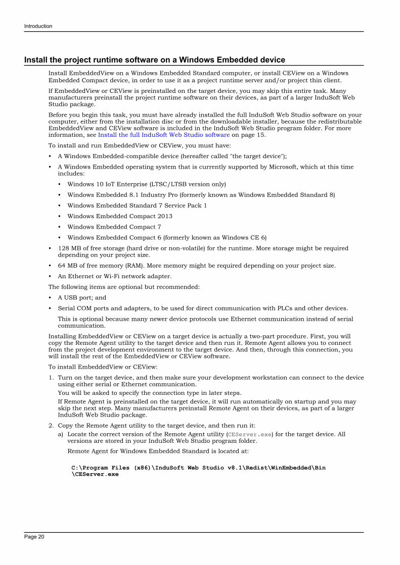
d) Run Remote Agent, or restart the device so that it runs automatically.
The Remote Agent window is displayed.
3. Configure the communication settings in Remote Agent:a) Click Setup.
The Setup dialog box is displayed.
b) Select the appropriate connection type: Serial Port or TCP/IP. If you select Serial Port, also select theCOM port and review the advanced settings.If you are already connected to the target device via ActiveSync, you do not need to select anotherconnection at this time. However, keep in mind how the target device will actually be used duringproject run time.
c) Click OK.
d) If you selected TCP/IP for the connection type, note the device's IP address.
e) Make sure that you leave Remote Agent running on the target device.
Introduction
Page 22
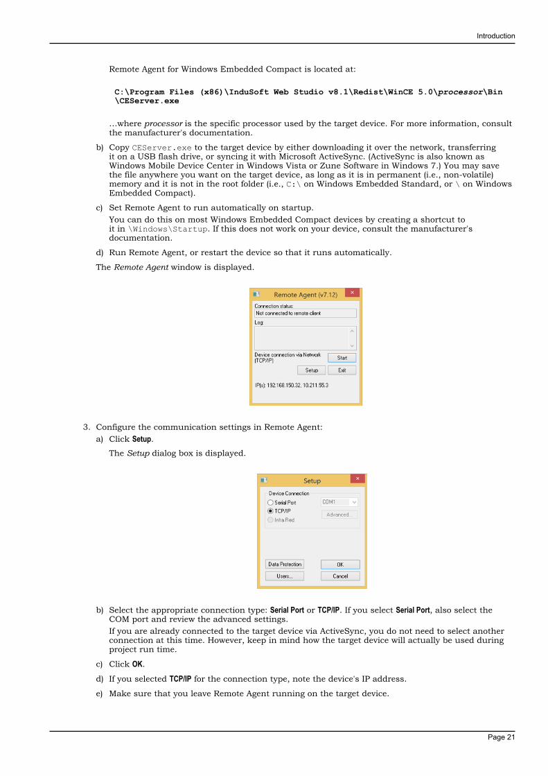
4. Use the Remote Management tool to connect to the target device:a) Run the project development application on your computer.
b) On the Home tab of the ribbon, in the Remote Management group, click Connect.The Remote Management dialog box is displayed.
c) Select the appropriate connection type for the target device: Host, Serial Port, or Microsoft ActiveSync. Ifyou select Host, also type the host name or IP address of the target device. If you select Serial Port,also select the COM port and verify the advanced serial communication settings.
d) Click Connect.If you are successfully connected to the target device, the connection status is shown in the Statusbox and the device's specifications are shown in the Platform box.
If you are not connected, check both the connection settings and the physical connections. Inparticular, if you have selected Host as the connection type, check to make sure that port 4322 isopen on any firewalls between your computer and the target station, including on the target stationitself.
Note:In some cases, the Remote Management tool may not be able to connect via MicrosoftActiveSync to a device running Windows CE 6.0 or later. This is because of a problem inthe default configuration of Windows CE 6.0. You can fix the problem by using a smallutility that is included with InduSoft Web Studio. The utility is located at:
C:\Program Files (x86)\InduSoft Web Studio v8.1\Redist\ActiveSyncUnlock.exe
Copy this file to the device using the stand-alone version of Microsoft ActiveSync and thenexecute the file on the device. It does not matter where the file is located on the device.When this is done, try again to use the Remote Management tool to connect to the device.
If you still cannot connect via Microsoft ActiveSync, empty the device's \Temp directoryand try again.
5. Install the rest of the EmbeddedView or CEView software on the target device:a) In Remote Management, click Install system files.
When the installation is finished, the target device's updated status is displayed in the Status box.
With EmbeddedView or CEView installed on the target device, you can now use it as a project runtimeand/or thin client.
Keep in mind that some run-time features are supported by InduSoft Web Studio (with a Runtime license)but not by EmbeddedView and CEView. If you develop a project that uses any of these features and thentry to run it in EmbeddedView or CEView, you might see unexpected behavior and possibly even seriouserrors during run time. Some features will be automatically blocked when you change your project's target

Introduction
Page 23
platform, but you should still be aware of the differences between runtime editions. For more information,see About the InduSoft Web Studio software components on page 10.
Introduction
Page 24
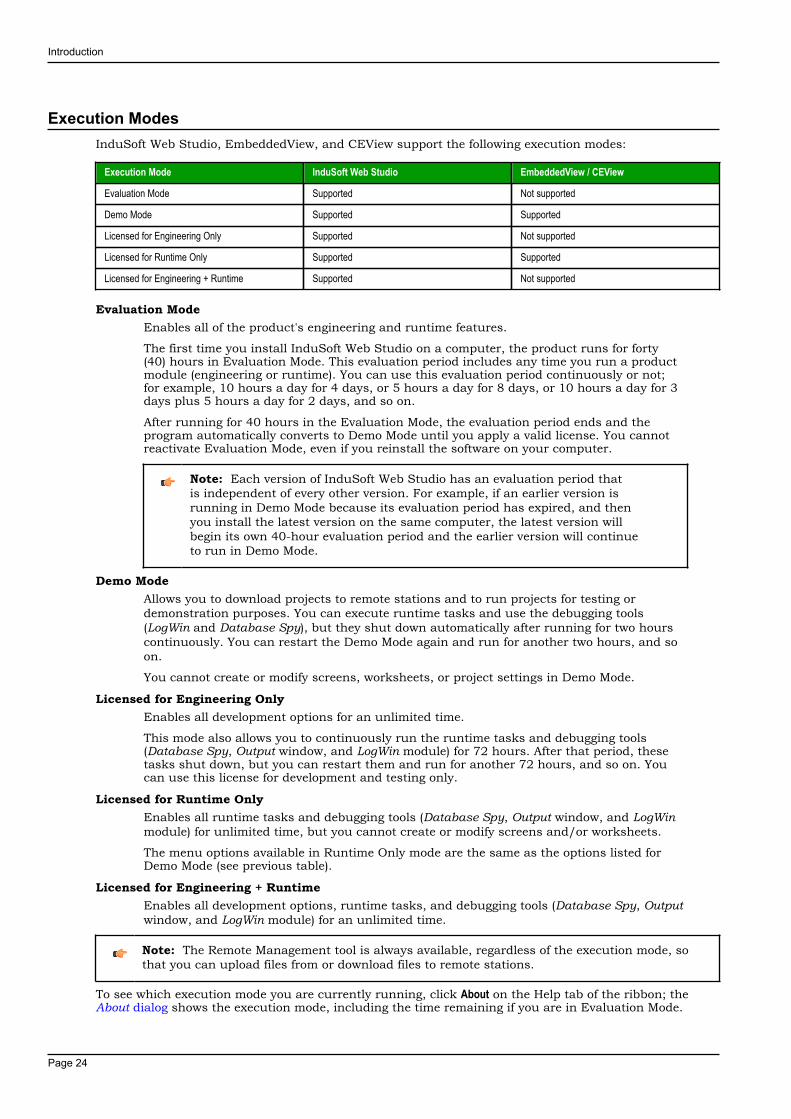
Execution ModesInduSoft Web Studio, EmbeddedView, and CEView support the following execution modes:
Execution Mode InduSoft Web Studio EmbeddedView / CEView
Evaluation Mode Supported Not supported
Demo Mode Supported Supported
Licensed for Engineering Only Supported Not supported
Licensed for Runtime Only Supported Supported
Licensed for Engineering + Runtime Supported Not supported
Evaluation ModeEnables all of the product's engineering and runtime features.
The first time you install InduSoft Web Studio on a computer, the product runs for forty(40) hours in Evaluation Mode. This evaluation period includes any time you run a productmodule (engineering or runtime). You can use this evaluation period continuously or not;for example, 10 hours a day for 4 days, or 5 hours a day for 8 days, or 10 hours a day for 3days plus 5 hours a day for 2 days, and so on.
After running for 40 hours in the Evaluation Mode, the evaluation period ends and theprogram automatically converts to Demo Mode until you apply a valid license. You cannotreactivate Evaluation Mode, even if you reinstall the software on your computer.
Note: Each version of InduSoft Web Studio has an evaluation period thatis independent of every other version. For example, if an earlier version isrunning in Demo Mode because its evaluation period has expired, and thenyou install the latest version on the same computer, the latest version willbegin its own 40-hour evaluation period and the earlier version will continueto run in Demo Mode.
Demo ModeAllows you to download projects to remote stations and to run projects for testing ordemonstration purposes. You can execute runtime tasks and use the debugging tools(LogWin and Database Spy), but they shut down automatically after running for two hourscontinuously. You can restart the Demo Mode again and run for another two hours, and soon.
You cannot create or modify screens, worksheets, or project settings in Demo Mode.
Licensed for Engineering OnlyEnables all development options for an unlimited time.
This mode also allows you to continuously run the runtime tasks and debugging tools(Database Spy, Output window, and LogWin module) for 72 hours. After that period, thesetasks shut down, but you can restart them and run for another 72 hours, and so on. Youcan use this license for development and testing only.
Licensed for Runtime OnlyEnables all runtime tasks and debugging tools (Database Spy, Output window, and LogWinmodule) for unlimited time, but you cannot create or modify screens and/or worksheets.
The menu options available in Runtime Only mode are the same as the options listed forDemo Mode (see previous table).
Licensed for Engineering + RuntimeEnables all development options, runtime tasks, and debugging tools (Database Spy, Outputwindow, and LogWin module) for an unlimited time.
Note: The Remote Management tool is always available, regardless of the execution mode, sothat you can upload files from or download files to remote stations.
To see which execution mode you are currently running, click About on the Help tab of the ribbon; theAbout dialog shows the execution mode, including the time remaining if you are in Evaluation Mode.
The Development Environment
Page 25
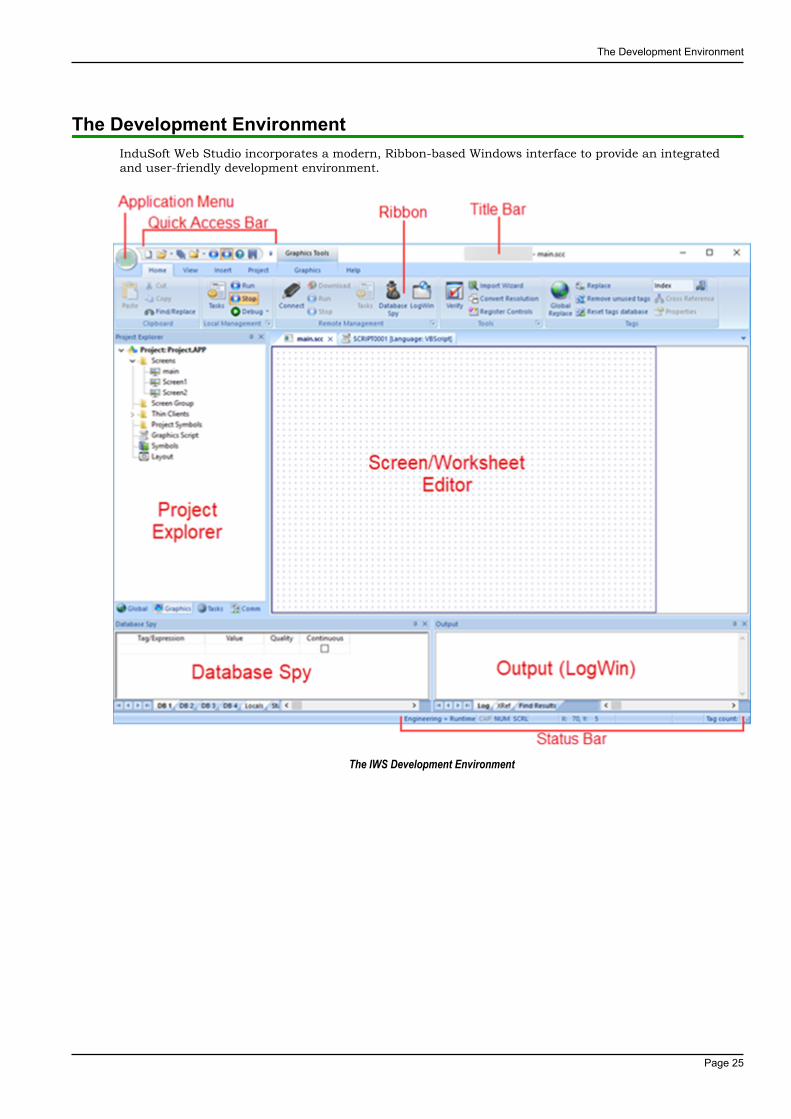
The Development EnvironmentInduSoft Web Studio incorporates a modern, Ribbon-based Windows interface to provide an integratedand user-friendly development environment.
The IWS Development Environment

The Development Environment
Page 26
Title BarThe Title Bar located along the top of the development environment displays the application name (e.g.,InduSoft Web Studio) followed by the name of the active screen or worksheet (if any).
Example of Title Bar
The Title Bar also provides the following buttons (from left to right):
•
Minimize button : Click to minimize the development environment window to the Taskbar.
• Restore Down / Maximize: Click to toggle the development environment window between two sizes:
•Restore Down button reduces the window to its original (default) size.
•
Maximize button enlarges the window to fill your computer screen.
•Close button : Click to save the database and then close the development environment. If youmodified any screens or worksheets, the application prompts you to save your work. This button'sfunction is similar to clicking Exit Application on the Application menu.
Note: Closing the development environment does not close either the project viewer or theruntime system, if they are running.
The Development Environment
Page 27
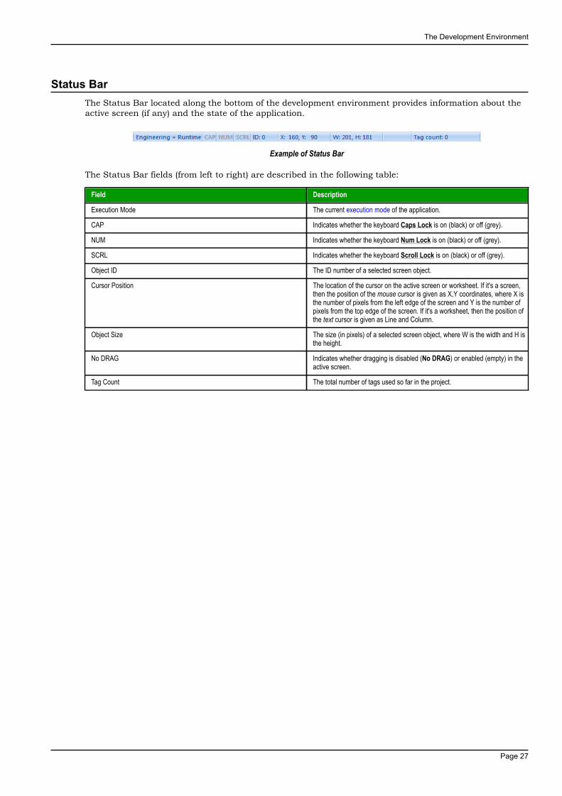
Status BarThe Status Bar located along the bottom of the development environment provides information about theactive screen (if any) and the state of the application.
Example of Status Bar
The Status Bar fields (from left to right) are described in the following table:
Field Description
Execution Mode The current execution mode of the application.
CAP Indicates whether the keyboard Caps Lock is on (black) or off (grey).
NUM Indicates whether the keyboard Num Lock is on (black) or off (grey).
SCRL Indicates whether the keyboard Scroll Lock is on (black) or off (grey).
Object ID The ID number of a selected screen object.
Cursor Position The location of the cursor on the active screen or worksheet. If it's a screen,then the position of the mouse cursor is given as X,Y coordinates, where X isthe number of pixels from the left edge of the screen and Y is the number ofpixels from the top edge of the screen. If it's a worksheet, then the position ofthe text cursor is given as Line and Column.
Object Size The size (in pixels) of a selected screen object, where W is the width and H isthe height.
No DRAG Indicates whether dragging is disabled (No DRAG) or enabled (empty) in theactive screen.
Tag Count The total number of tags used so far in the project.
The Development Environment
Page 28
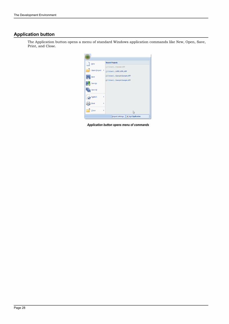
Application buttonThe Application button opens a menu of standard Windows application commands like New, Open, Save,Print, and Close.
Application button opens menu of commands
The Development Environment
Page 29
Quick Access ToolbarThe Quick Access Toolbar is a customizable toolbar that contains a set of commands that are independentof the ribbon tab that is currently displayed.
Move the Quick Access ToolbarThe Quick Access Toolbar can be located in one of two places:
• Upper-left corner next to the Application button (default location); or
• Below the ribbon, where it can run the full length of the application window.
If you don't want the Quick Access Toolbar to be displayed in its current location, you can move it to theother location:
1.Click Customize Quick Access Toolbar .
2. In the list, click Show Below Ribbon or Show Above Ribbon.
Add a command to the Quick Access ToolbarYou can add a command to the Quick Access Toolbar directly from commands that are displayed on theribbon:
1. On the ribbon, click the appropriate tab or group to display the command that you want to add to theQuick Access Toolbar.
2. Right-click the command, and then click Add to Quick Access Toolbar on the shortcut menu.
You can also add and remove commands — as well as reset the toolbar to its default — using theCustomize dialog:
1.Click Customize Quick Access Toolbar .

The Development Environment
Page 30
2. In the list, click More Commands. The Customize dialog is displayed.
Customize Quick Access Toolbar dialog3. In the Choose commands from menu, select the appropriate Ribbon tab. The commands from that tab are
displayed in the Commands list.
4. In the Commands list, select the command that you want to add to the Quick Access Toolbar.
5. Click Add.
Only commands can be added to the Quick Access Toolbar. The contents of most lists, such as indentand spacing values and individual styles, which also appear on the ribbon, cannot be added to the QuickAccess Toolbar.
The Development Environment
Page 31
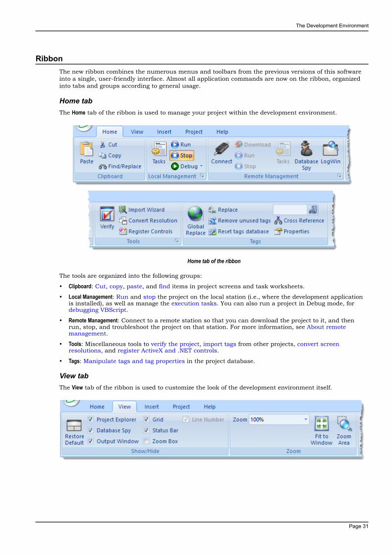
RibbonThe new ribbon combines the numerous menus and toolbars from the previous versions of this softwareinto a single, user-friendly interface. Almost all application commands are now on the ribbon, organizedinto tabs and groups according to general usage.
Home tabThe Home tab of the ribbon is used to manage your project within the development environment.
Home tab of the ribbon
The tools are organized into the following groups:
• Clipboard: Cut, copy, paste, and find items in project screens and task worksheets.
• Local Management: Run and stop the project on the local station (i.e., where the development applicationis installed), as well as manage the execution tasks. You can also run a project in Debug mode, fordebugging VBScript.
• Remote Management: Connect to a remote station so that you can download the project to it, and thenrun, stop, and troubleshoot the project on that station. For more information, see About remotemanagement.
• Tools: Miscellaneous tools to verify the project, import tags from other projects, convert screenresolutions, and register ActiveX and .NET controls.
• Tags: Manipulate tags and tag properties in the project database.
View tabThe View tab of the ribbon is used to customize the look of the development environment itself.
The Development Environment
Page 32
View tab of the ribbon
The tools are organized into the following groups:
• Show/Hide: Show and hide the different parts of the development environment, as well as restore thedefault layout.
• Zoom: Zoom in and out of the screen editor.
• Options: Change the language and font used in the development environment.
• Window: Arrange the windows in the development environment.
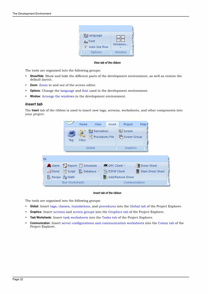
Insert tabThe Insert tab of the ribbon is used to insert new tags, screens, worksheets, and other components intoyour project.
Insert tab of the ribbon
The tools are organized into the following groups:
• Global: Insert tags, classes, translations, and procedures into the Global tab of the Project Explorer.
• Graphics: Insert screens and screen groups into the Graphics tab of the Project Explorer.
• Task Worksheets: Insert task worksheets into the Tasks tab of the Project Explorer.
• Communication: Insert server configurations and communication worksheets into the Comm tab of theProject Explorer.
The Development Environment
Page 33
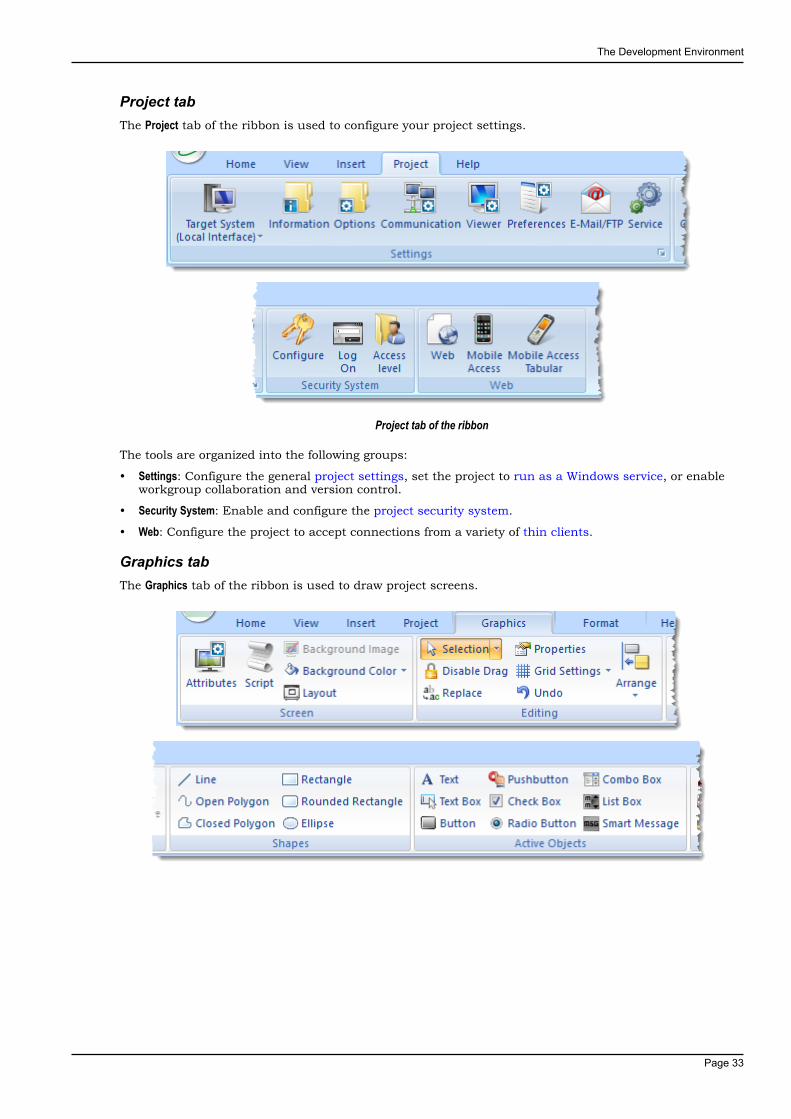
Project tabThe Project tab of the ribbon is used to configure your project settings.
Project tab of the ribbon
The tools are organized into the following groups:
• Settings: Configure the general project settings, set the project to run as a Windows service, or enableworkgroup collaboration and version control.
• Security System: Enable and configure the project security system.
• Web: Configure the project to accept connections from a variety of thin clients.
Graphics tabThe Graphics tab of the ribbon is used to draw project screens.
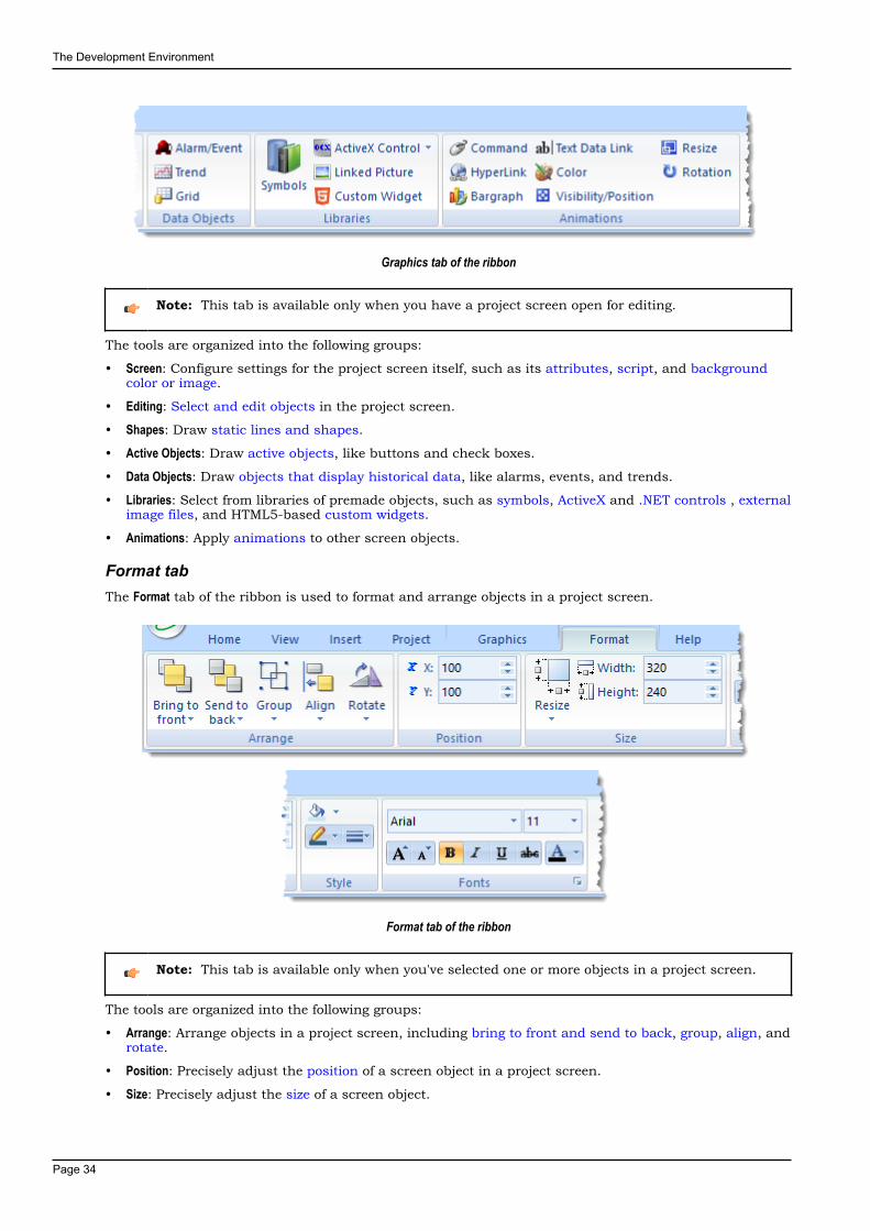
The Development Environment
Page 34
Graphics tab of the ribbon
Note: This tab is available only when you have a project screen open for editing.
The tools are organized into the following groups:
• Screen: Configure settings for the project screen itself, such as its attributes, script, and backgroundcolor or image.
• Editing: Select and edit objects in the project screen.
• Shapes: Draw static lines and shapes.
• Active Objects: Draw active objects, like buttons and check boxes.
• Data Objects: Draw objects that display historical data, like alarms, events, and trends.
• Libraries: Select from libraries of premade objects, such as symbols, ActiveX and .NET controls , externalimage files, and HTML5-based custom widgets.
• Animations: Apply animations to other screen objects.
Format tabThe Format tab of the ribbon is used to format and arrange objects in a project screen.
Format tab of the ribbon
Note: This tab is available only when you've selected one or more objects in a project screen.
The tools are organized into the following groups:
• Arrange: Arrange objects in a project screen, including bring to front and send to back, group, align, androtate.
• Position: Precisely adjust the position of a screen object in a project screen.
• Size: Precisely adjust the size of a screen object.

The Development Environment
Page 35
• Style: Change the fill and line color of a screen object.
• Fonts: Change the caption font of a screen object.
Help tabThe Help tab of the ribbon provides additional help with using the software.
Help tab of the ribbon
The tools are organized into the following groups:
• Documentation: Access the documentation for the development application, including this help file /technical reference and notes for the individual communication drivers.
• Information: Access other information about InduSoft Web Studio, including the license agreement,product website, and release notes, as well as system and support details that make it easier forCustomer Support to assist you.

The Development Environment
Page 36
Project ExplorerThe Project Explorer organizes all of the screens, worksheets, and other items that comprise your projectand presents them in an expandable tree-view.
To open a folder and view its contents, either click the Expand icon to the left of the folder or double-click the folder itself.
To close a folder, click the Collapse icon to the left of the folder.
If you right-click any item in the Project Explorer, then a shortcut menu will appear with contextualcommands for that item.
There are four main sections, or tabs, in the Project Explorer: Global, Graphics, Tasks, and Comm.
Global tabThe Global tab of the Project Explorer contains the project tags database, as well as other features thatapply to the entire project such as the security system, VBScript procedures, and UI translation.
Global tab of the Project Explorer
The folders on the Global tab are described in the following sections:Project Tags
The project tags database contains all of the data tags that you create during projectdevelopment, such as screen tags (e.g., button1_state) or tags that read from / write toconnected devices.
ClassesClasses are compound tags that you can create to associate a set of values, rather than asingle value, with an object. For example, where you may normally create separate tags for atank's pressure, its temperature, and its fill level, you can instead create a "tank" class thatincludes all three.
Shared DatabaseThe shared database contains tags that were created in another program and then importedinto or integrated with your project.
System Tags
The Development Environment
Page 37
System tags are predefined values such as the date, the time, the name of the current user,and so on. You can use these values to develop supervisory functions and housekeepingroutines.
All system tags are read-only, which means you cannot add, edit, or remove these tags fromthe database.
SecurityIf you choose to enable it, you can use the project security system to control who may log onto your project and what they may do during runtime.
ProceduresProcedures are VBScript functions and sub-routines that can be called by any other scriptin your project.
Event LoggerThe event logger saves important runtime messages and task results to an externaldatabase.
TranslationYou can use the translation table to develop a multilingual user interface (MUI) for yourproject.
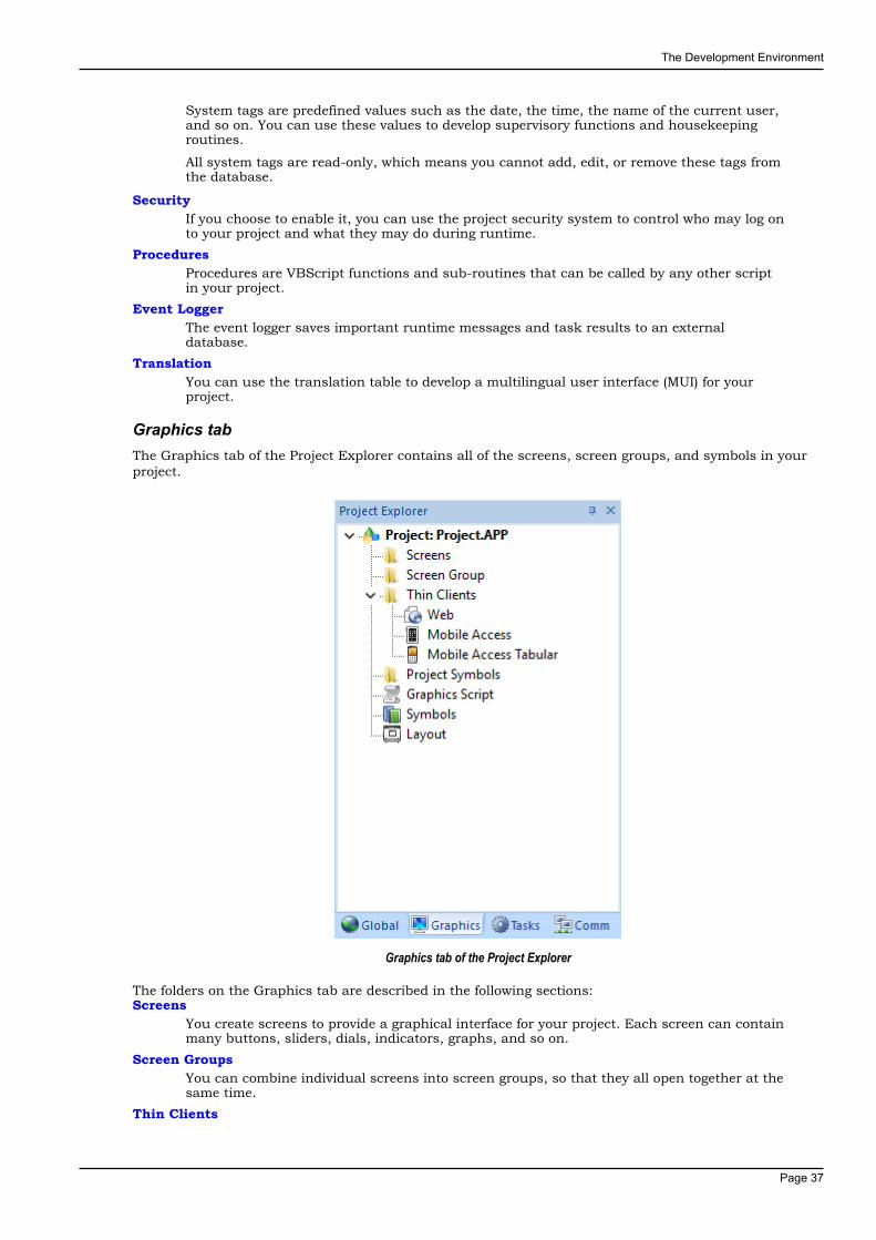
Graphics tabThe Graphics tab of the Project Explorer contains all of the screens, screen groups, and symbols in yourproject.
Graphics tab of the Project Explorer
The folders on the Graphics tab are described in the following sections:Screens
You create screens to provide a graphical interface for your project. Each screen can containmany buttons, sliders, dials, indicators, graphs, and so on.
Screen GroupsYou can combine individual screens into screen groups, so that they all open together at thesame time.
Thin Clients
The Development Environment
Page 38
You can deploy your project as a web application to be accessed by thin clients such asdesktop web browsers, tablets, and smartphones. You can even deploy different versions ofyour project with different levels of functionality for each type of client.
Project SymbolsThis folder contains all of the custom symbols that you create for your project. A symbol isa group of interconnected screen objects that work together to perform a single function —for example, lines, rectangles, and text fragments that have been arranged to make a slidercontrol.
Graphics ScriptYou can use this worksheet to define VBScript sub-routines that are called only when thegraphics module starts (i.e., when a client station connects to the server and displays thegraphical interface), while it is running, and when it ends.
SymbolsThe symbols library contains not only the custom symbols that you create (see ProjectSymbols above), but also a large selection of premade symbols that are installed with thedevelopment application.
LayoutThe layout editor displays all of the screens the are currently open for editing. You can use itto visualize how the screens are arranged together and reuse screens in multiple layouts —for example, to create a common navigation bar across your entire project.
Tasks tabThe Tasks tab of the Project Explorer organizes the worksheets that are processed as background tasks(i.e., server-based maintenance tasks that are not directly related to screen operations or device I/O)during project runtime.
Tasks tab of the Project Explorer
The folders on the Tasks tab are described in the following sections:Alarms
You can use Alarm worksheets to define when alarms are trigged, how they must behandled, and what messages they generate.

The Development Environment
Page 39
(You can then use the Alarm/Event Control screen object to display your alarms on screen,but that is a separate procedure.)
TrendsYou can use Trend worksheets to select project tags that should be displayed as data trendsand/or saved as historical data.
(You can then use the Trend Control screen object to actually display your trends on screen,but that is a separate procedure.)
RecipesYou can use Recipe worksheets to select project tags that will load values from and/or savevalues to an external file. These worksheets are typically used to execute process recipes,but you can store any type of information such as passwords, operation logs, and so on.
(You can then call the Recipe function to actually run a configured Recipe worksheet, butthat is a separate procedure.)
ReportsYou can use Report worksheets to design runtime reports that are either sent to a printer orsaved to disk.
(You can then call the Report function to actually run a configured Report worksheet, butthat is a separate procedure.)
MathYou can use Math worksheets to develop complex runtime logic using the built-in scriptinglanguage.
ScriptYou can use Script worksheets to develop complex runtime logic using VBScript.
SchedulerYou can use Scheduler worksheets to run commands at specified times, dates, or triggerevents.
DatabaseYou can use Database worksheets to set up connections and exchange data with externaldatabases using the standard ADO.NET interface.
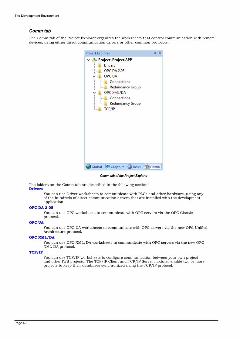
The Development Environment
Page 40
Comm tabThe Comm tab of the Project Explorer organizes the worksheets that control communication with remotedevices, using either direct communication drivers or other common protocols.
Comm tab of the Project Explorer
The folders on the Comm tab are described in the following sections:Drivers
You can use Driver worksheets to communicate with PLCs and other hardware, using anyof the hundreds of direct communication drivers that are installed with the developmentapplication.
OPC DA 2.05You can use OPC worksheets to communicate with OPC servers via the OPC Classicprotocol.
OPC UAYou can use OPC UA worksheets to communicate with OPC servers via the new OPC UnifiedArchitecture protocol.
OPC XML/DAYou can use OPC XML/DA worksheets to communicate with OPC servers via the new OPCXML-DA protocol.
TCP/IPYou can use TCP/IP worksheets to configure communication between your own projectand other IWS projects. The TCP/IP Client and TCP/IP Server modules enable two or moreprojects to keep their databases synchronized using the TCP/IP protocol.

The Development Environment
Page 41
Screen/Worksheet EditorUse the powerful, object-oriented screen editor to create and edit a variety of screens and worksheets foryour projects. You can input information using your mouse and keyboard, output control data to yourprocesses, and automatically update screens based on data input from your processes.
Screen/Worksheet Editor
Other screen editor features include:
• Simple point-and-click, drag-and-drop interface
• Grouping objects to preserve the construction steps of individual objects
• Editing objects without having to ungroup internal object components or groups
• Handling bitmap objects and background bitmaps
• Status line support in project windows and dialogs
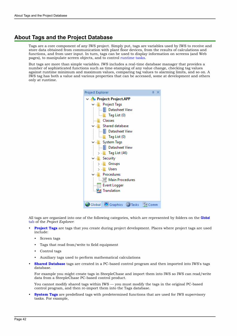
About Tags and the Project Database
Page 42
About Tags and the Project DatabaseTags are a core component of any IWS project. Simply put, tags are variables used by IWS to receive andstore data obtained from communication with plant floor devices, from the results of calculations andfunctions, and from user input. In turn, tags can be used to display information on screens (and Webpages), to manipulate screen objects, and to control runtime tasks.
But tags are more than simple variables. IWS includes a real-time database manager that provides anumber of sophisticated functions such as time-stamping of any value change, checking tag valuesagainst runtime minimum and maximum values, comparing tag values to alarming limits, and so on. AIWS tag has both a value and various properties that can be accessed, some at development and othersonly at runtime.
All tags are organized into one of the following categories, which are represented by folders on the Globaltab of the Project Explorer:
• Project Tags are tags that you create during project development. Places where project tags are usedinclude:
• Screen tags
• Tags that read from/write to field equipment
• Control tags
• Auxiliary tags used to perform mathematical calculations
• Shared Database tags are created in a PC-based control program and then imported into IWS's tagsdatabase.
For example you might create tags in SteepleChase and import them into IWS so IWS can read/writedata from a SteepleChase PC-based control product.
You cannot modify shared tags within IWS — you must modify the tags in the original PC-basedcontrol program, and then re-import them into the Tags database.
• System Tags are predefined tags with predetermined functions that are used for IWS supervisorytasks. For example,

About Tags and the Project Database
Page 43
• Date tags hold the current date in string format
• Time tags hold the current time in string format
Most system tags are read-only, which means you cannot add, edit, or remove these tags from thedatabase.
To see a list of the system tags, select the Global tab in the Project Explorer, open the System Tags folder,and open the Tag List subfolder.
After creating a tag, you can use it anywhere within the project, and you can use the same tag for morethan one object or attribute.
About Tags and the Project Database
Page 44
Understanding the Tag Name SyntaxObserve the following guidelines when naming a tag:
• Your tag names must be unique — you cannot specify the same name for two different tags (orfunctions). If you type an existing tag name, IWS recognizes that the name exists and will not createthe new tag.
• You must begin each tag name with a letter. Otherwise, you can use letters, numbers, and theunderscore character (_) in your tag name.
• You cannot use the following symbols in a tag name:
` ~ ! @ # $ % ^ & * ( ) - = \ + \ [ ] { } < > ?
• You can use a maximum of 255 characters for a tag name or a class member name.You can useuppercase and lowercase characters. Tag names are not case sensitive. Because IWS does notdifferentiate between uppercase and lowercase characters, you can use both to make tag names morereadable. (For example: TankLevel instead of tanklevel.)
• Tag names must be different from system tag names and math functions.
Note: Use the @ character at the beginning of a tag name to indicate that the tag will be used asan indirect tag in the project.
Some valid tag examples include:
• Temperature
• pressure1
• count
• x
About Tags and the Project Database
Page 45
Choosing the Tag Data TypeAnother consideration when designing a tag is what type of data the tag will receive. IWS recognizes thefollowing, standard tag data types:
• Boolean (one bit): Simple boolean with the possible values of 0 (false) and 1 (true). Equivalent to the"bool" data type in C++. Typically used for turning objects off and on or for closing and opening objects.
• Integer (four bytes): Integer number (positive, negative, or zero) internally stored as a signed 32-bit.Equivalent to the "signed long int" data type in C++. Typically used for counting whole numbers orsetting whole number values. Examples: 0, 5, −200.
• Real (floating point, eight bytes): Real number that is stored internally as a signed 64-bit. Equivalent tothe "double" data type in C++. Typically used for measurements or for decimal or fractional values.
• String (alphanumeric data, up to 1024 characters): Character string up to 1024 characters that holdsletters, numbers, or special characters. Supports both ASCII and UNICODE characters. Examples:Recipe product X123, 01/01/90, *** On ***.
You can also assign a new tag to a class that you have previously created.
You can find these tag types (and their respective icons) in the Global tab of the Project Explorer.
About Tags and the Project Database
Page 46
Using Array TagsIWS tags can consist of a single value or an array of values.
Note: The maximum array size is 16384 as long as it does not exceed the maximum numberof tags supported by the license (Product Type) selected for the project. Each array position(including the position 0) counts as one tag for licensing restrictions, because each position hasan independent value.
An array tag is a set of tags with the same name, which is identified by indexes (a matrix of n lines and 1column). The maximum array size depends on the product specification. You can use the following syntaxto access an array tag:
ArrayTagName[ArrayIndex]
For example: tank[0], tank[1], tank[2], and tank[500].
Note: You must specify a maximum index for each array tag in the size column of any datasheet.You can specify n to indicate the array tag has positions from 0 to n. For example, if the size ofTagA is 3, the tag elements could be TagA[0], TagA[1], TagA[2], and TagA[3].
Use the array tag whenever possible because it optimizes memory use and simplifies the configurationtask. For example, if you want a display to monitor each tank, you could use array tags to configure asingle display containing tags linked to any tank. For example (using the tk tag as an index containingthe number of the tank): pressure[tk], temperature[tk], and temperature[tk+1].
An array index can be a tag, a numeric value, or an expression with the arithmetic operator "+".
Note: When you refer to an array with an index using the + arithmetic operation, you must usethe following syntax:
ArrayTagName[NumValue1+NumValue2]
Where NumValue1 and NumValue2 can be an integer tag or a numerical constant. For example:temperature[tk+2] or temperature[tk+6].
Using array tags in any IWS task can save a signification amount of project development time. Forexample, if you needed tag points related to the temperature of four tanks. The conventional configurationmethod is the following:
• temperature1: high temperature on tank 1
• temperature2: high temperature on tank 2
• temperature3: high temperature on tank 3
• temperature4: high temperature on tank 4
Using array tags simplifies this task, as follows:
• temperature[j]: high temperature on tank {j}
Note: When you create a four-position array tag, the system creates five positions (from 0 to 4).For example:
tag_example[15] //start position=0, end position=15
Therefore, the tag_example[15] array has 16 elements.
When using another tag to reference the index of an array, if the value of the tag is outside the size of thearray, then the following results are given:
• If IndexTag is greater than the size of the array, then MyArray[IndexTag] will point to the endposition of the array; and
• If IndexTag is less than 0, then MyArray[IndexTag] will point to the start position of the array.
About Tags and the Project Database
Page 47
Array TagsAn array tag consists of a set of tags that all have the same name, but use unique array indexes (a matrixof n lines and one column) to differentiate between each tag. An array index can be a fixed value, anothertag or an expression. Maximum array sizes are determined by product specifications.
You can use array tags to:
• Simplify configurations
• Enable multiplexing in screens, recipes, and communication interfaces
• Save development time during tag declaration
You specify array tags in one of two formats:
• For a simple array tag, type:
ArrayTagName[ArrayIndex]
• For a complex array tag (where the array index is an expression consisting of a tag and an arithmeticoperation), type:
ArrayTagName[ArrayIndex+c]
Where:
• ArrayTagName is the tag name;
• [ArrayIndex] is the unique index (fixed value or another tag);
• + is an arithmetic operation; and
• c is a numerical constant.
Note:
• You must specify a maximum index for each array tag by typing a value (n) in the ArraySize column of an Project Tags datasheet or in the Array Size field on a New Tag dialog.
When you create an n-position array tag, IWS actually creates n+1 positions (from 0 to n). Forexample, if you specify ArrayTag[15], the array will have 16 elements, where 0 is the startposition and 15 is the end position.
• You must not use spaces in an array tag.
When IWS reads a tag it begins with the first character and continues until it finds thefirst space or null character. Consequently, the system does not recognize any charactersfollowing the space as part of the array tag.
For example, if you type a[second + 1], IWS regards a[second as the tag and considersit invalid because IWS does not find (recognize) the closing bracket. However, if you typea[second+1], this is a valid array tag.
You can specify an array tag wherever you would use a variable name. Also, because array tags greatlysimplify configuration tasks and can save development time, we suggest using them whenever possible.
For example, suppose you want to monitor the temperature of four tanks. The conventional configurationmethod is:
• temperature1 — high temperature on tank 1
• temperature2 — high temperature on tank 2
• temperature3 — high temperature on tank 3
• temperature4 — high temperature on tank 4
You can use array tags to simplify this task as follows (where [n] represents the tank number):
• temperature[n] — high temperature on tank [n]
The following table contains some additional examples of an array tag:
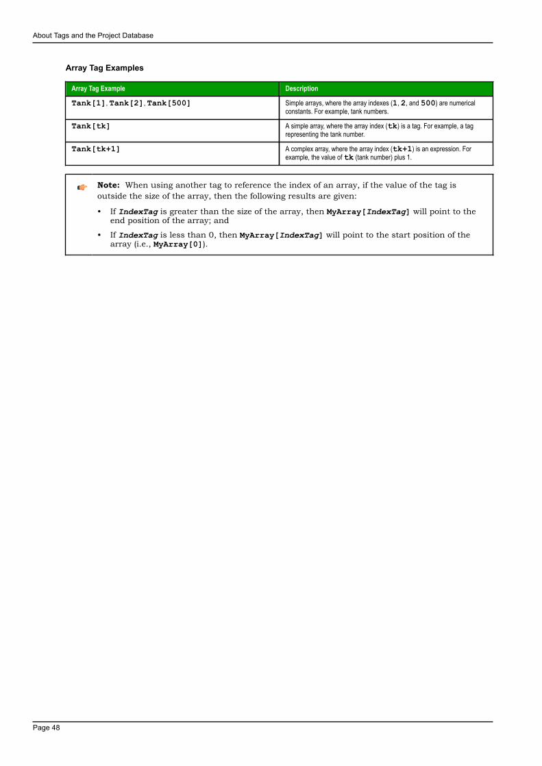
About Tags and the Project Database
Page 48
Array Tag Examples
Array Tag Example Description
Tank[1], Tank[2], Tank[500] Simple arrays, where the array indexes (1, 2, and 500) are numericalconstants. For example, tank numbers.
Tank[tk] A simple array, where the array index (tk) is a tag. For example, a tagrepresenting the tank number.
Tank[tk+1] A complex array, where the array index (tk+1) is an expression. Forexample, the value of tk (tank number) plus 1.
Note: When using another tag to reference the index of an array, if the value of the tag isoutside the size of the array, then the following results are given:
• If IndexTag is greater than the size of the array, then MyArray[IndexTag] will point to theend position of the array; and
• If IndexTag is less than 0, then MyArray[IndexTag] will point to the start position of thearray (i.e., MyArray[0]).

About Tags and the Project Database
Page 49
About indirect tagsIWS supports indirect access to tags in the database. For example, consider a tag X of the String type.This tag can hold the name of any other tag in the database (that is, it can provide a pointer to any othertype of tag, including a class type). The syntax for an indirect tag is straightforward: @IndirectTagName.For example, assume that a tag named X holds a "TEMP" string. Reading and/or writing to @X providesaccess to the value of the TEMP variable.
Note: Any tag created as a string-type tag is potentially an indirect tag (pointer).
To refer to a class-type tag, you can declare a string-type tag that points to a class tag. For example:
Class TANK with members Level
Tag TK of the class TANK
Tag XCLASS of the String type
To access the TK.Level value, you must store the " TK.Level" value within the XCLASS tag and use thesyntax, @XCLASS. You can also refer to a member of a class-type tag directly; identifying a class-type thatpoints to a class member.
For example:
Class TANK with members Level
Tag TK of the class TANK
Tag XCLASS of the class TANK
To access the TK.Level value, you must store the "TK" value within the XCLASS tag and use the syntax,@XCLASS.Level.
When creating tags for indirect use, place an X in the tag column rather than creating them as strings.For the type, write the type of tag for which you are creating a reference. Follow the XCLASS example: @ZInteger, @X Class:TANK.
Indirect TagsIndirect tags "point" to other database tags (including class-type tags). Using indirect tags can savedevelopment time because they keep you from having to create duplicate tags (and the logic built intothem).
You create an indirect tag from any string-type tag simply by typing the @ symbol in front of the tag name@TagName.
• To reference a simple tag, assume the strX tag (a string tag) holds the value "Tank", which is thename of another tag, then reading from or writing to @strX provides access to the value of the Tanktag.
• To reference a class-type tag and member, you simply create a string tag that points to the class tagand the member. For example, if a tag strX (a string tag) holds the value "Tank.Level", which isthe name of the class tag, then reading from or writing to @strX provides access to the value of theTank.Level member.
• You can also point directly to a class-type tag member; by identifying a class-type that points to a classmember. For example: to access the Tank.Level member of the class, you must store the "Tank"value within the strX tag and use the syntax, @strX.Level.

Tutorial: Building a Simple Project
Page 50
Tutorial: Building a Simple ProjectThis section explains, using a step-by-step tutorial, how to build a simple project, as well as how to selectand configure an I/O driver.
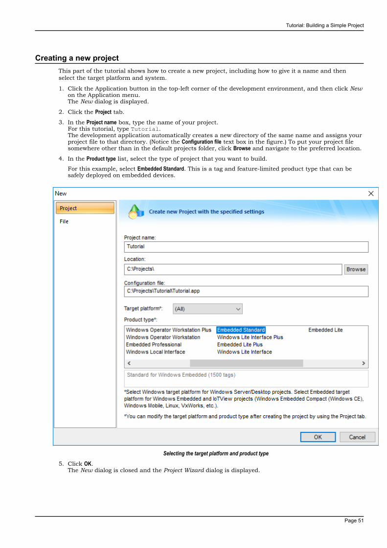
Tutorial: Building a Simple Project
Page 51
Creating a new projectThis part of the tutorial shows how to create a new project, including how to give it a name and thenselect the target platform and system.
1. Click the Application button in the top-left corner of the development environment, and then click Newon the Application menu.The New dialog is displayed.
2. Click the Project tab.
3. In the Project name box, type the name of your project.For this tutorial, type Tutorial.The development application automatically creates a new directory of the same name and assigns yourproject file to that directory. (Notice the Configuration file text box in the figure.) To put your project filesomewhere other than in the default projects folder, click Browse and navigate to the preferred location.
4. In the Product type list, select the type of project that you want to build.
For this example, select Embedded Standard. This is a tag and feature-limited product type that can besafely deployed on embedded devices.
Selecting the target platform and product type5. Click OK.
The New dialog is closed and the Project Wizard dialog is displayed.
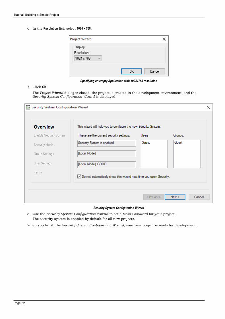
Tutorial: Building a Simple Project
Page 52
6. In the Resolution list, select 1024 x 768.
Specifying an empty Application with 1024x768 resolution7. Click OK.
The Project Wizard dialog is closed, the project is created in the development environment, and theSecurity System Configuration Wizard is displayed.
Security System Configuration Wizard8. Use the Security System Configuration Wizard to set a Main Password for your project.
The security system is enabled by default for all new projects.
When you finish the Security System Configuration Wizard, your new project is ready for development.

Tutorial: Building a Simple Project
Page 53
Specifying the startup screenThis part of the tutorial shows how to open the project settings and then specify which screen should bedisplayed on startup.
• Use the Information tab to provide information that identifies the project (such as project description,revision number, Company name, Author's name, field equipment, and general notes).
• Use the Options tab to specify generic settings for the project, such as the Target System, AutomaticTranslation, Alarm history and Events, Default Database and Shared Tags.
• Use the Viewer tab to enable/disable the runtime desktop parameters.
• Use the Communication tab to specify communication parameters relating to the project in general.
• Use the Preferences tab to enable/disable warning messages when using the development application.
To specify the startup screen:
1. On the Project tab of the ribbon, in the Settings group, click Viewer.The Project Settings dialog is displayed with the Viewer tab selected.
2. In the Startup screen box, type main.scc.When you run the project, it will automatically display the main screen (or whichever screen youspecify) first. You can specify a screen before you create it, but if the screen has been created, then youcan also select it from the list.
3. Click OK.
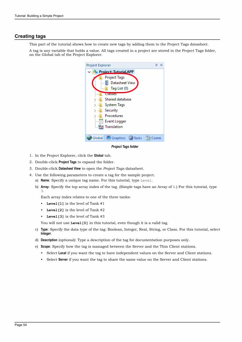
Tutorial: Building a Simple Project
Page 54
Creating tagsThis part of the tutorial shows how to create new tags by adding them to the Project Tags datasheet.
A tag is any variable that holds a value. All tags created in a project are stored in the Project Tags folder,on the Global tab of the Project Explorer.
Project Tags folder
1. In the Project Explorer, click the Global tab.
2. Double-click Project Tags to expand the folder.
3. Double-click Datasheet View to open the Project Tags datasheet.
4. Use the following parameters to create a tag for the sample project.a) Name: Specify a unique tag name. For this tutorial, type Level.
b) Array: Specify the top array index of the tag. (Simple tags have an Array of 0.) For this tutorial, type3.
Each array index relates to one of the three tanks:
• Level[1] is the level of Tank #1
• Level[2] is the level of Tank #2
• Level[3] is the level of Tank #3
You will not use Level[0] in this tutorial, even though it is a valid tag.
c) Type: Specify the data type of the tag: Boolean, Integer, Real, String, or Class. For this tutorial, selectInteger.
d) Description (optional): Type a description of the tag for documentation purposes only.
e) Scope: Specify how the tag is managed between the Server and the Thin Client stations.
• Select Local if you want the tag to have independent values on the Server and Client stations.
• Select Server if you want the tag to share the same value on the Server and Client stations.
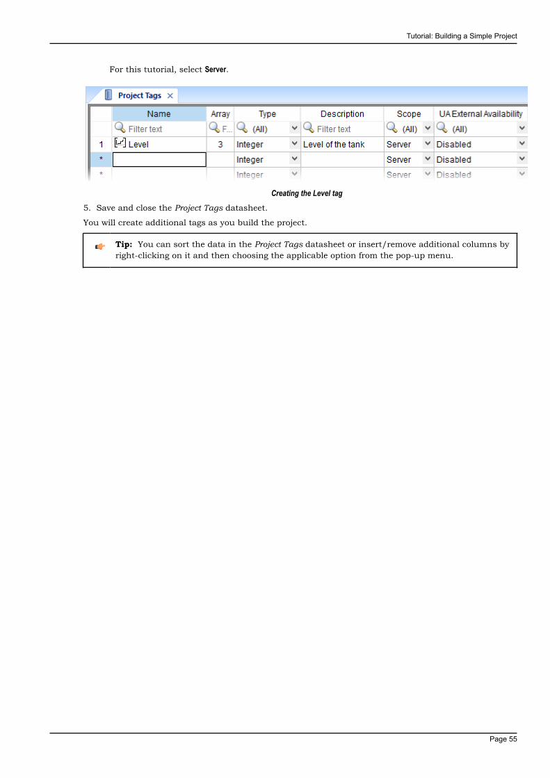
Tutorial: Building a Simple Project
Page 55
For this tutorial, select Server.
Creating the Level tag5. Save and close the Project Tags datasheet.
You will create additional tags as you build the project.
Tip: You can sort the data in the Project Tags datasheet or insert/remove additional columns byright-clicking on it and then choosing the applicable option from the pop-up menu.
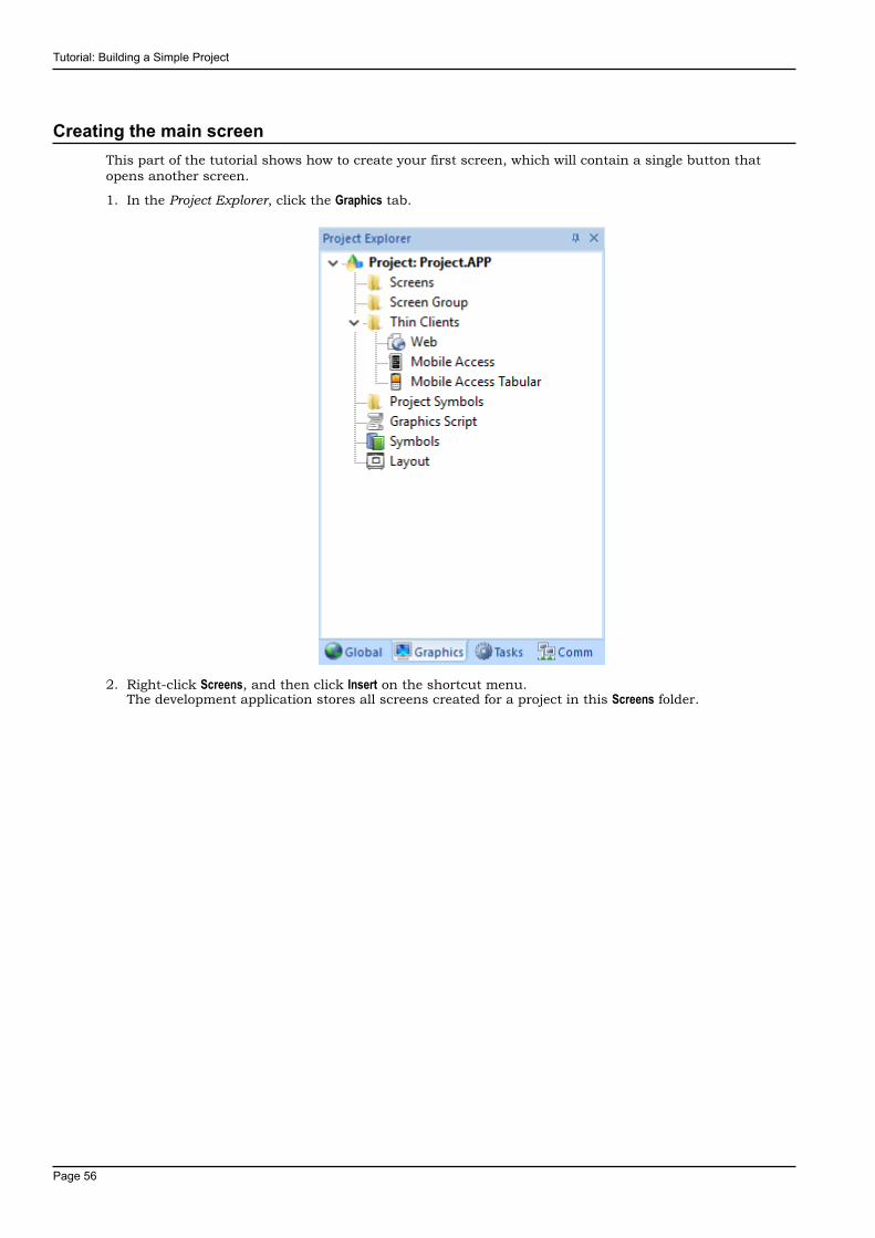
Tutorial: Building a Simple Project
Page 56
Creating the main screenThis part of the tutorial shows how to create your first screen, which will contain a single button thatopens another screen.
1. In the Project Explorer, click the Graphics tab.
2. Right-click Screens, and then click Insert on the shortcut menu.The development application stores all screens created for a project in this Screens folder.
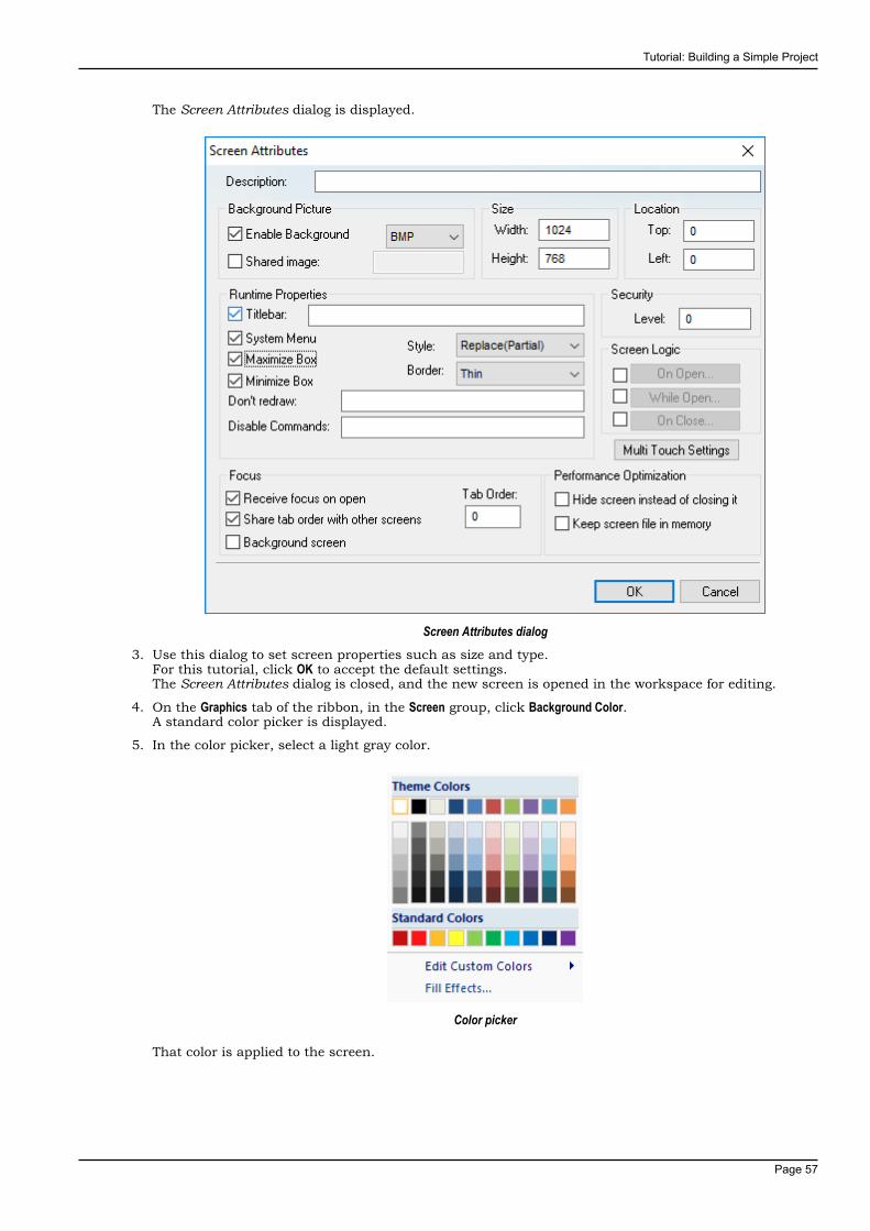
Tutorial: Building a Simple Project
Page 57
The Screen Attributes dialog is displayed.
Screen Attributes dialog3. Use this dialog to set screen properties such as size and type.
For this tutorial, click OK to accept the default settings.The Screen Attributes dialog is closed, and the new screen is opened in the workspace for editing.
4. On the Graphics tab of the ribbon, in the Screen group, click Background Color.A standard color picker is displayed.
5. In the color picker, select a light gray color.
Color picker
That color is applied to the screen.

Tutorial: Building a Simple Project
Page 58
Drawing the main screen's titleThis part of the tutorial shows how to draw the main screen's title using a Text object.
1. On the Graphics tab of the ribbon, in the Active Objects group, click Text.Your mouse cursor changes from an arrow to a crosshair.
2. Click on the screen, type Welcome to the Tutorial Application, and then press Return.This creates a new Text object with the specified text.
3. Double-click the object to open its Object Properties dialog.
Object Properties: Text dialog
• Double-clicking on any screen object opens an Object Properties dialog containing the properties forthat object. The properties shown in the dialog change depending on the type of object.
• The Object Properties dialog also contains a pin button that controls whether this dialog remainsopen. The button changes state (and function) each time you click on it, as follows:
• When the pin button is released, the focus is passed to the object on the screen as soon as itis selected. It is recommended that this button is kept released when you want to manipulatethe objects (Copy, Paste, Cut, or Delete). Although the Object Properties dialog is on the top, thekeyboard commands (Ctrl+C, Ctrl+V, Ctrl+X, or Del) are sent directly to the objects.
• When the pin button is pressed, the focus is kept on the Object Properties dialog, even when youclick the objects on the screen. We recommend you keep this button pressed when you wantto modify the settings of the objects. You can click an object and type the new property valuedirectly in the Object Properties dialog (it is not necessary to click on the window to bring focusto it). Also, when the pin button is pressed, the Object Properties dialog does not automaticallyclose when you click on the screen.
4. Click Fonts to open Font dialog, and then specify the font settings.For this tutorial…
• Font is Arial• Font style is Regular• Size is 20
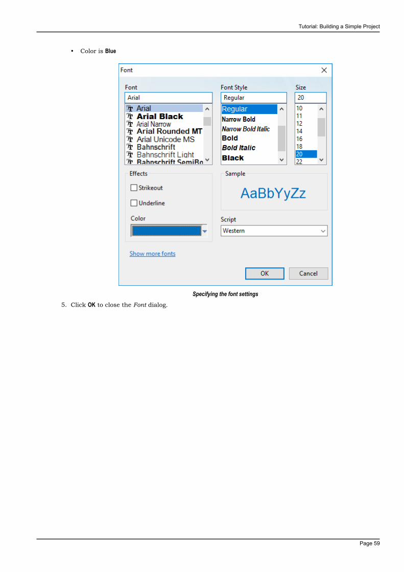
Tutorial: Building a Simple Project
Page 59
• Color is Blue
Specifying the font settings5. Click OK to close the Font dialog.
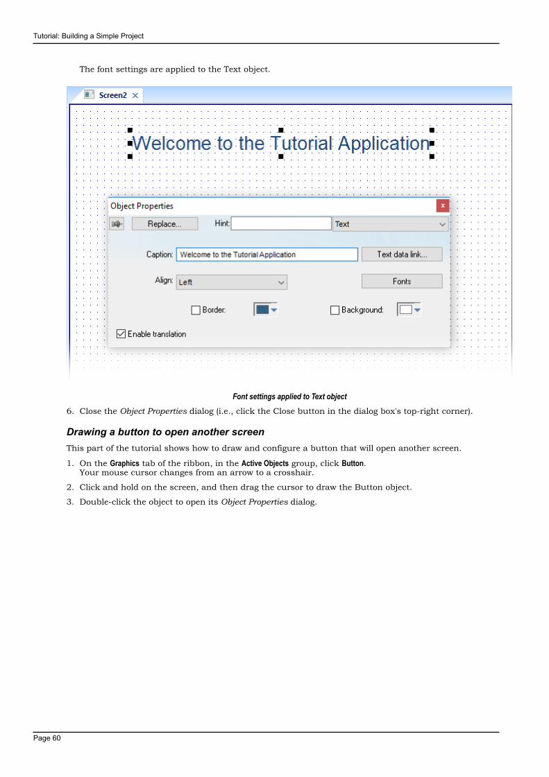
Tutorial: Building a Simple Project
Page 60
The font settings are applied to the Text object.
Font settings applied to Text object6. Close the Object Properties dialog (i.e., click the Close button in the dialog box's top-right corner).
Drawing a button to open another screenThis part of the tutorial shows how to draw and configure a button that will open another screen.
1. On the Graphics tab of the ribbon, in the Active Objects group, click Button.Your mouse cursor changes from an arrow to a crosshair.
2. Click and hold on the screen, and then drag the cursor to draw the Button object.
3. Double-click the object to open its Object Properties dialog.
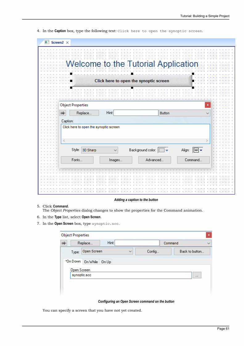
Tutorial: Building a Simple Project
Page 61
4. In the Caption box, type the following text: Click here to open the synoptic screen.
Adding a caption to the button5. Click Command.
The Object Properties dialog changes to show the properties for the Command animation.
6. In the Type list, select Open Screen.
7. In the Open Screen box, type synoptic.scc.
Configuring an Open Screen command on the button
You can specify a screen that you have not yet created.

Tutorial: Building a Simple Project
Page 62
8. Close the Object Properties dialog.
Saving and closing the main screenThis part of the tutorial shows how to properly save and close a screen.
1. Click the Application button at the top-left of the development environment, and then click Save on theApplication menu.A standard Windows Save dialog is displayed.
2. In the File name box, type main.
3. Click Save.The file is saved in your project folder (at <project name>\Screen\main.scc), and the Save dialog isclosed.
4. Click the Application button at the top-left of the development environment, and then click Close on theApplication menu.
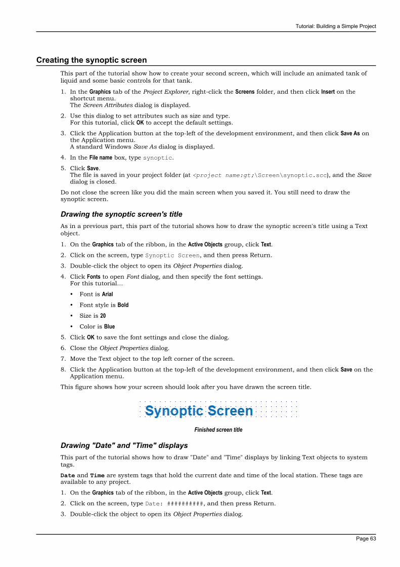
Tutorial: Building a Simple Project
Page 63
Creating the synoptic screenThis part of the tutorial show how to create your second screen, which will include an animated tank ofliquid and some basic controls for that tank.
1. In the Graphics tab of the Project Explorer, right-click the Screens folder, and then click Insert on theshortcut menu.The Screen Attributes dialog is displayed.
2. Use this dialog to set attributes such as size and type.For this tutorial, click OK to accept the default settings.
3. Click the Application button at the top-left of the development environment, and then click Save As onthe Application menu.A standard Windows Save As dialog is displayed.
4. In the File name box, type synoptic.
5. Click Save.The file is saved in your project folder (at <project name:gt;\Screen\synoptic.scc), and the Savedialog is closed.
Do not close the screen like you did the main screen when you saved it. You still need to draw thesynoptic screen.
Drawing the synoptic screen's titleAs in a previous part, this part of the tutorial shows how to draw the synoptic screen's title using a Textobject.
1. On the Graphics tab of the ribbon, in the Active Objects group, click Text.2. Click on the screen, type Synoptic Screen, and then press Return.
3. Double-click the object to open its Object Properties dialog.
4. Click Fonts to open Font dialog, and then specify the font settings.For this tutorial…
• Font is Arial• Font style is Bold• Size is 20• Color is Blue
5. Click OK to save the font settings and close the dialog.
6. Close the Object Properties dialog.
7. Move the Text object to the top left corner of the screen.
8. Click the Application button at the top-left of the development environment, and then click Save on theApplication menu.
This figure shows how your screen should look after you have drawn the screen title.
Finished screen title
Drawing "Date" and "Time" displaysThis part of the tutorial shows how to draw "Date" and "Time" displays by linking Text objects to systemtags.
Date and Time are system tags that hold the current date and time of the local station. These tags areavailable to any project.
1. On the Graphics tab of the ribbon, in the Active Objects group, click Text.2. Click on the screen, type Date: ##########, and then press Return.
3. Double-click the object to open its Object Properties dialog.
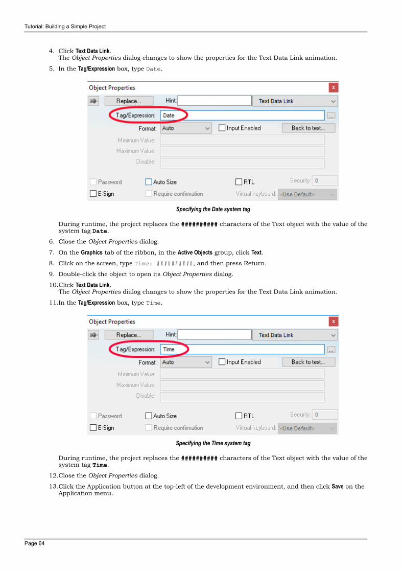
Tutorial: Building a Simple Project
Page 64
4. Click Text Data Link.The Object Properties dialog changes to show the properties for the Text Data Link animation.
5. In the Tag/Expression box, type Date.
Specifying the Date system tag
During runtime, the project replaces the ########## characters of the Text object with the value of thesystem tag Date.
6. Close the Object Properties dialog.
7. On the Graphics tab of the ribbon, in the Active Objects group, click Text.8. Click on the screen, type Time: ##########, and then press Return.
9. Double-click the object to open its Object Properties dialog.
10.Click Text Data Link.The Object Properties dialog changes to show the properties for the Text Data Link animation.
11.In the Tag/Expression box, type Time.
Specifying the Time system tag
During runtime, the project replaces the ########## characters of the Text object with the value of thesystem tag Time.
12.Close the Object Properties dialog.
13.Click the Application button at the top-left of the development environment, and then click Save on theApplication menu.
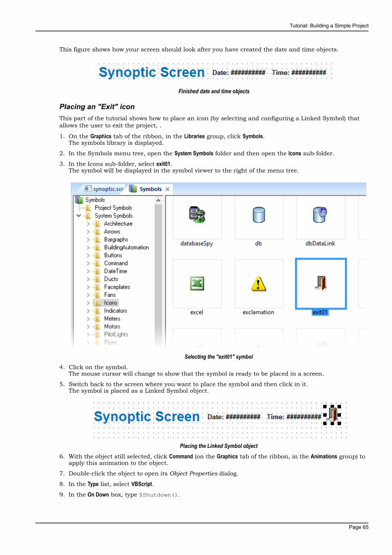
Tutorial: Building a Simple Project
Page 65
This figure shows how your screen should look after you have created the date and time objects.
Finished date and time objects
Placing an "Exit" iconThis part of the tutorial shows how to place an icon (by selecting and configuring a Linked Symbol) thatallows the user to exit the project, .
1. On the Graphics tab of the ribbon, in the Libraries group, click Symbols.The symbols library is displayed.
2. In the Symbols menu tree, open the System Symbols folder and then open the Icons sub-folder.
3. In the Icons sub-folder, select exit01.The symbol will be displayed in the symbol viewer to the right of the menu tree.
Selecting the "exit01" symbol4. Click on the symbol.
The mouse cursor will change to show that the symbol is ready to be placed in a screen.
5. Switch back to the screen where you want to place the symbol and then click in it.The symbol is placed as a Linked Symbol object.
Placing the Linked Symbol object6. With the object still selected, click Command (on the Graphics tab of the ribbon, in the Animations group) to
apply this animation to the object.
7. Double-click the object to open its Object Properties dialog.
8. In the Type list, select VBScript.9. In the On Down box, type $Shutdown().
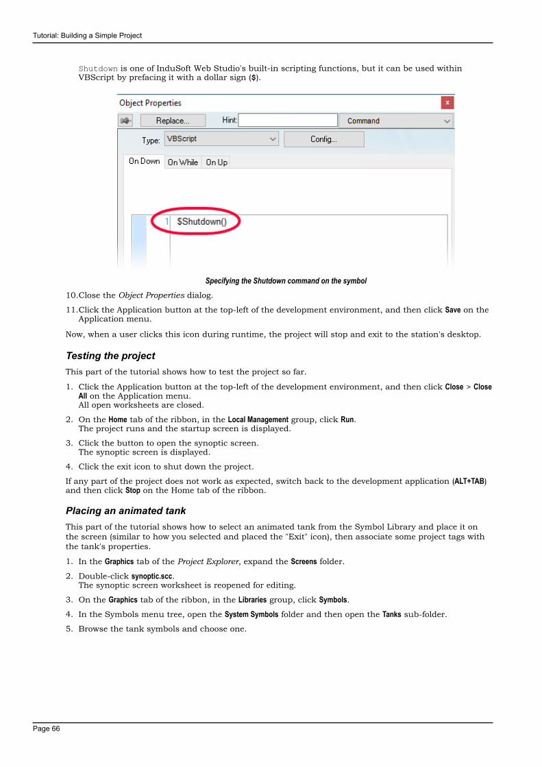
Tutorial: Building a Simple Project
Page 66
Shutdown is one of InduSoft Web Studio's built-in scripting functions, but it can be used withinVBScript by prefacing it with a dollar sign ($).
Specifying the Shutdown command on the symbol10.Close the Object Properties dialog.
11.Click the Application button at the top-left of the development environment, and then click Save on theApplication menu.
Now, when a user clicks this icon during runtime, the project will stop and exit to the station's desktop.
Testing the projectThis part of the tutorial shows how to test the project so far.
1. Click the Application button at the top-left of the development environment, and then click Close > CloseAll on the Application menu.All open worksheets are closed.
2. On the Home tab of the ribbon, in the Local Management group, click Run.The project runs and the startup screen is displayed.
3. Click the button to open the synoptic screen.The synoptic screen is displayed.
4. Click the exit icon to shut down the project.
If any part of the project does not work as expected, switch back to the development application (ALT+TAB)and then click Stop on the Home tab of the ribbon.
Placing an animated tankThis part of the tutorial shows how to select an animated tank from the Symbol Library and place it onthe screen (similar to how you selected and placed the "Exit" icon), then associate some project tags withthe tank's properties.
1. In the Graphics tab of the Project Explorer, expand the Screens folder.
2. Double-click synoptic.scc.The synoptic screen worksheet is reopened for editing.
3. On the Graphics tab of the ribbon, in the Libraries group, click Symbols.
4. In the Symbols menu tree, open the System Symbols folder and then open the Tanks sub-folder.
5. Browse the tank symbols and choose one.
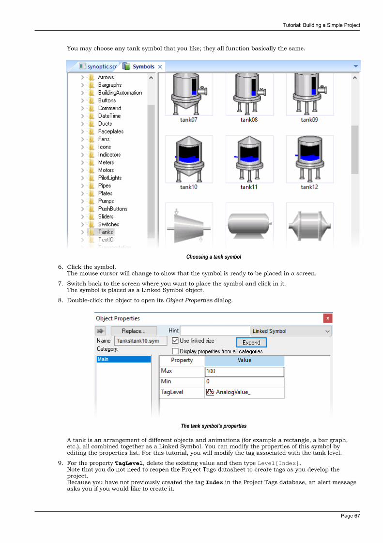
Tutorial: Building a Simple Project
Page 67
You may choose any tank symbol that you like; they all function basically the same.
Choosing a tank symbol6. Click the symbol.
The mouse cursor will change to show that the symbol is ready to be placed in a screen.
7. Switch back to the screen where you want to place the symbol and click in it.The symbol is placed as a Linked Symbol object.
8. Double-click the object to open its Object Properties dialog.
The tank symbol's properties
A tank is an arrangement of different objects and animations (for example a rectangle, a bar graph,etc.), all combined together as a Linked Symbol. You can modify the properties of this symbol byediting the properties list. For this tutorial, you will modify the tag associated with the tank level.
9. For the property TagLevel, delete the existing value and then type Level[Index].Note that you do not need to reopen the Project Tags datasheet to create tags as you develop theproject.Because you have not previously created the tag Index in the Project Tags database, an alert messageasks you if you would like to create it.

Tutorial: Building a Simple Project
Page 68
10.Click Yes.A New Tag dialog is displayed.
11.Configure the new tag with Array as 0, Type as Integer, and Scope as Local.
Configuring a new tag12.Click OK to close the New Tag dialog.
You can use the tag Index to set the array position of the tag Level, and show the level for any of thethree tanks in the same object:
• When Index equals 1, the tank object shows the level of Tank #1 (i.e., Level[1]);
• When Index equals 2, the tank object shows the level of Tank #2 (i.e., Level[2]); and
• When Index equals 3, the tank object shows the level of Tank #3 (i.e., Level[3]).
Also, because the tag scope is local, the tag can have different values for the Server and Client stationsat the same time. Consequently, the local user (i.e., the Server station) can be monitoring the level ofTank #1 while the remote user (i.e., the Client station) is monitoring the level of Tank #2.
13.Close the Object Properties dialog.
14.Click the Application button at the top-left of the development environment, and then click Save on theApplication menu.
This figure shows how your screen should look after you've created the tank object.
Finished tank object
Placing a level sliderThis part of the tutorial shows how to select a slider control from the Symbol Library and then connect itto the animated tank.
1. On the Graphics tab of the ribbon, in the Libraries group, click Symbols.
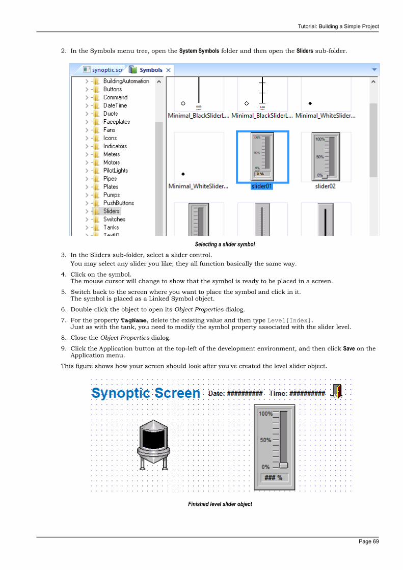
Tutorial: Building a Simple Project
Page 69
2. In the Symbols menu tree, open the System Symbols folder and then open the Sliders sub-folder.
Selecting a slider symbol3. In the Sliders sub-folder, select a slider control.
You may select any slider you like; they all function basically the same way.
4. Click on the symbol.The mouse cursor will change to show that the symbol is ready to be placed in a screen.
5. Switch back to the screen where you want to place the symbol and click in it.The symbol is placed as a Linked Symbol object.
6. Double-click the object to open its Object Properties dialog.
7. For the property TagName, delete the existing value and then type Level[Index].Just as with the tank, you need to modify the symbol property associated with the slider level.
8. Close the Object Properties dialog.
9. Click the Application button at the top-left of the development environment, and then click Save on theApplication menu.
This figure shows how your screen should look after you've created the level slider object.
Finished level slider object
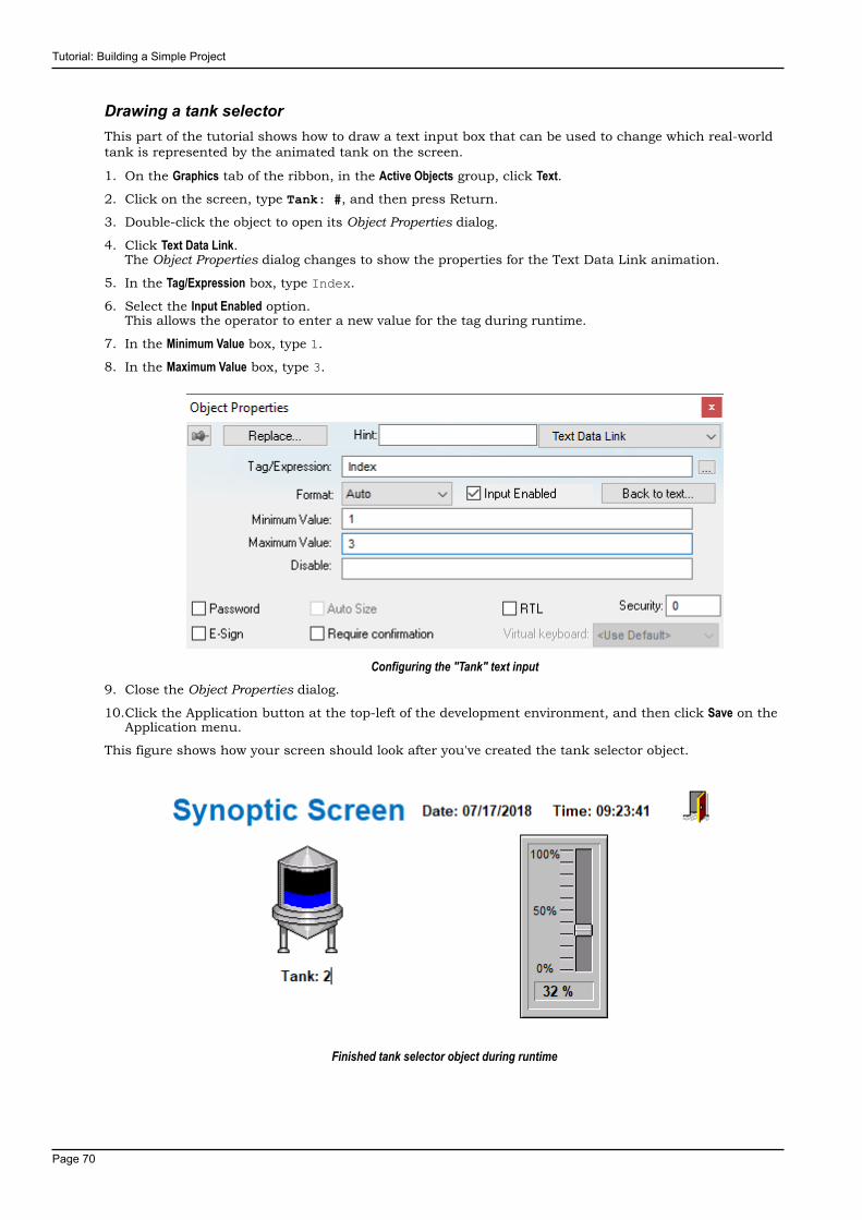
Tutorial: Building a Simple Project
Page 70
Drawing a tank selectorThis part of the tutorial shows how to draw a text input box that can be used to change which real-worldtank is represented by the animated tank on the screen.
1. On the Graphics tab of the ribbon, in the Active Objects group, click Text.2. Click on the screen, type Tank: #, and then press Return.
3. Double-click the object to open its Object Properties dialog.
4. Click Text Data Link.The Object Properties dialog changes to show the properties for the Text Data Link animation.
5. In the Tag/Expression box, type Index.
6. Select the Input Enabled option.This allows the operator to enter a new value for the tag during runtime.
7. In the Minimum Value box, type 1.
8. In the Maximum Value box, type 3.
Configuring the "Tank" text input9. Close the Object Properties dialog.
10.Click the Application button at the top-left of the development environment, and then click Save on theApplication menu.
This figure shows how your screen should look after you've created the tank selector object.
Finished tank selector object during runtime
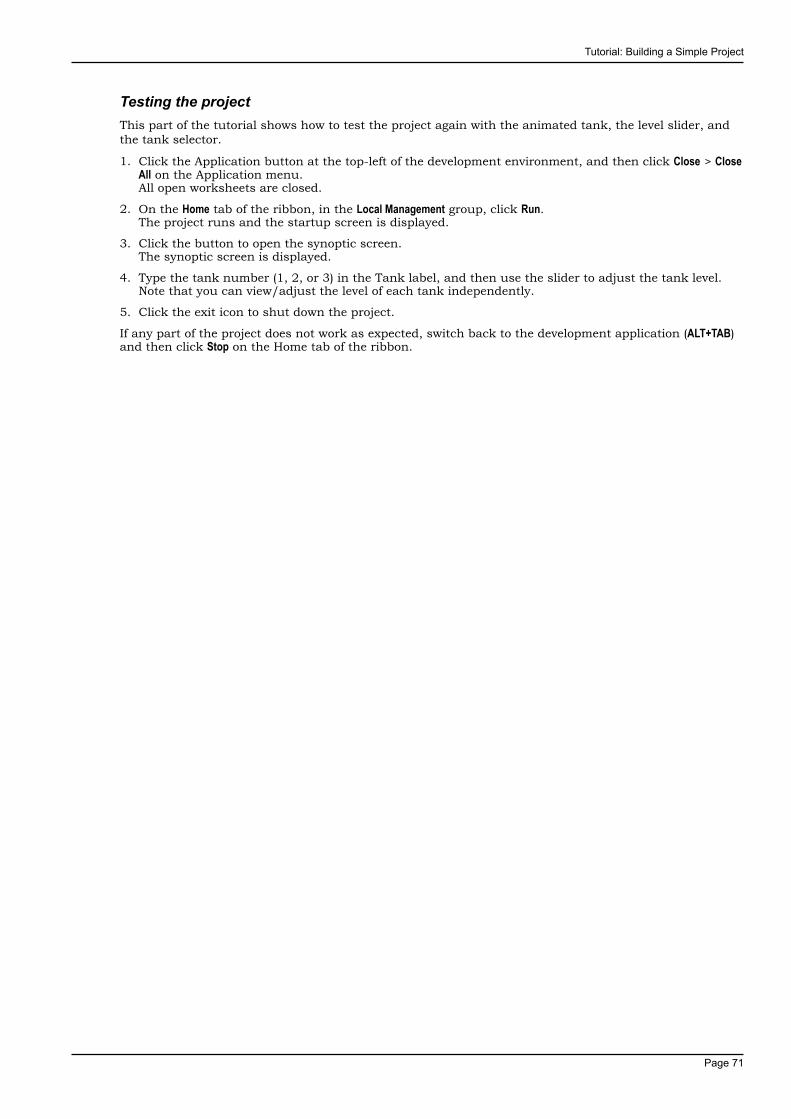
Tutorial: Building a Simple Project
Page 71
Testing the projectThis part of the tutorial shows how to test the project again with the animated tank, the level slider, andthe tank selector.
1. Click the Application button at the top-left of the development environment, and then click Close > CloseAll on the Application menu.All open worksheets are closed.
2. On the Home tab of the ribbon, in the Local Management group, click Run.The project runs and the startup screen is displayed.
3. Click the button to open the synoptic screen.The synoptic screen is displayed.
4. Type the tank number (1, 2, or 3) in the Tank label, and then use the slider to adjust the tank level.Note that you can view/adjust the level of each tank independently.
5. Click the exit icon to shut down the project.
If any part of the project does not work as expected, switch back to the development application (ALT+TAB)and then click Stop on the Home tab of the ribbon.
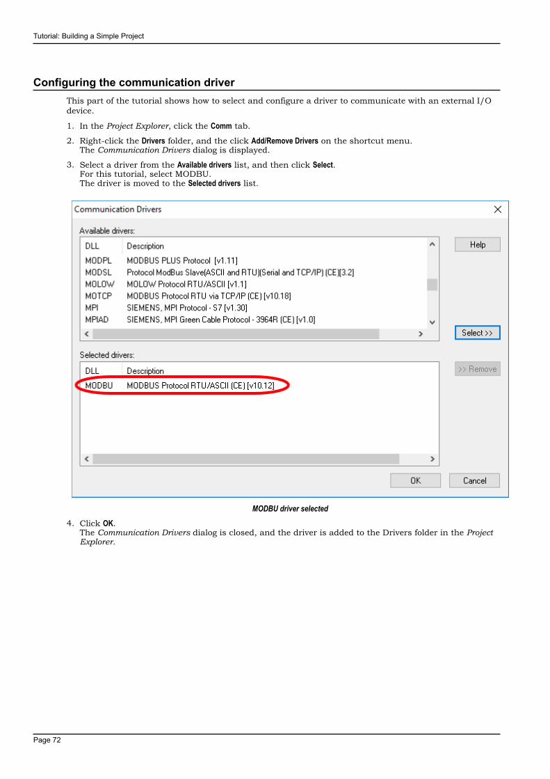
Tutorial: Building a Simple Project
Page 72
Configuring the communication driverThis part of the tutorial shows how to select and configure a driver to communicate with an external I/Odevice.
1. In the Project Explorer, click the Comm tab.
2. Right-click the Drivers folder, and the click Add/Remove Drivers on the shortcut menu.The Communication Drivers dialog is displayed.
3. Select a driver from the Available drivers list, and then click Select.For this tutorial, select MODBU.The driver is moved to the Selected drivers list.
MODBU driver selected4. Click OK.
The Communication Drivers dialog is closed, and the driver is added to the Drivers folder in the ProjectExplorer.

Tutorial: Building a Simple Project
Page 73
5. In the Project Explorer, right-click the MODBU folder, and then click Settings on the shortcut menu.
The Communication Settings dialog is displayed.
Communication Settings dialog for MODBU driver6. Configure the communication settings as needed for the target device.
For this tutorial, accept the default settings.
Note: For more information about a specific driver, click Communication Drivers on the Help tabof the ribbon.
7. Click OK to close the dialog.
8. In the Project Explorer, right-click the MODBU folder and then click Insert on the shortcut menu.A new driver worksheet named MODBU001.drv is created and opened for editing.
9. Configure the worksheet header:a) In the Description box, type Tutorial Modbus.
This setting is for documentation only; it does not affect the runtime project in any way.
b) In the Enable Read When Idle box, type 1.This setting is a trigger that takes a Boolean value. A value of 1 — either entered manually as aboveor evaluated from a tag/expression — forces your project to continue reading tag values from thetarget device even when there are no changes in value.
c) In the Enable Write On Tag Change box, type 1.
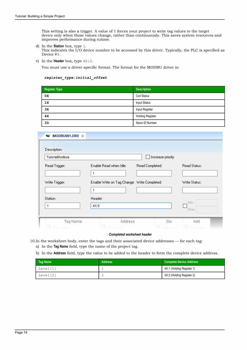
Tutorial: Building a Simple Project
Page 74
This setting is also a trigger. A value of 1 forces your project to write tag values to the targetdevice only when those values change, rather than continuously. This saves system resources andimproves performance during rutime.
d) In the Station box, type 1.This indicates the I/O device number to be accessed by this driver. Typically, the PLC is specified asDevice #1.
e) In the Header box, type 4X:0.
You must use a driver-specific format. The format for the MODBU driver is:
register_type:initial_offset
Register Type Description
0X Coil Status
1X Input Status
3X Input Register
4X Holding Register
ID Slave ID Number
Completed worksheet header10.In the worksheet body, enter the tags and their associated device addresses — for each tag:
a) In the Tag Name field, type the name of the project tag.
b) In the Address field, type the value to be added to the header to form the complete device address.
Tag Name Address Complete Device Address
Level[1] 1 4X:1 (Holding Register 1)
Level[2] 2 4X:2 (Holding Register 2)
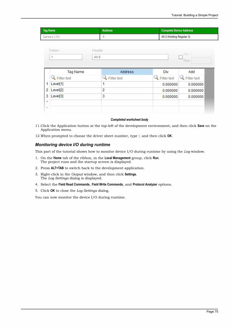
Tutorial: Building a Simple Project
Page 75
Tag Name Address Complete Device Address
Level[3] 3 4X:3 (Holding Register 3)
Completed worksheet body11.Click the Application button at the top-left of the development environment, and then click Save on the
Application menu.
12.When prompted to choose the driver sheet number, type 1 and then click OK.
Monitoring device I/O during runtimeThis part of the tutorial shows how to monitor device I/O during runtime by using the Log window.
1. On the Home tab of the ribbon, in the Local Management group, click Run.The project runs and the startup screen is displayed.
2. Press ALT+TAB to switch back to the development application.
3. Right-click in the Output window, and then click Settings.The Log Settings dialog is displayed.
4. Select the Field Read Commands, Field Write Commands, and Protocol Analyzer options.
5. Click OK to close the Log Settings dialog.
You can now monitor the device I/O during runtime.

Tutorial: Building a Simple Project
Page 76
Downloading your project to a Windows Embedded deviceThis part of the tutorial shows how to download your project to a Windows Embedded device, such as aplant-floor HMI panel.
After configuring a project and testing it locally (on the development station), you can download it toa remote station — either a Windows PC that is running IWS or a Windows Embedded device that isrunning EmbeddedView or CEView.
1. On the desktop of the remote station, click Start > All Apps > InduSoft Web Studio v8.1 > IWS v8.1 Remote Agent.The Remote Agent utility runs.
Remote Agent utility2. Click Setup.
The Setup dialog is displayed.
3. Select the type of connection — Serial, TCP/IP, or Infrared — between the remote station and thedevelopment station.
Note: For better performance, we recommend that you use TCP/IP whenever possible.
Selecting TCP/IP on the remote station4. Click OK to close the Setup dialog, but leave the Remote Agent utility running on the remote station.
5. In the development application, click Connect on the Home tab of the ribbon.

Tutorial: Building a Simple Project
Page 77
The Remote Management dialog is displayed.
Remote Management dialog6. Select the type of connection to the target (remote) station.
This selection should match the selection you previously made in the Remote Agent utility on theremote station.
7. If you selected Host, type the host name or IP address of the remote station.
8. Click Connect.If you successfully connect to the remote station, then information about that station is displayed inthe Status and Platform boxes.
9. If the remote station is a Windows Embedded device, click Install system files.The system files are installed on the remote station.
10.Click the Project tab.
11.Click Download.The project files are downloaded to the remote station.
12.Click Run.Your IWS project is run on the remote station.
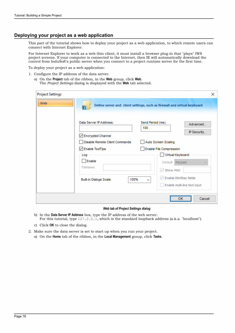
Tutorial: Building a Simple Project
Page 78
Deploying your project as a web applicationThis part of the tutorial shows how to deploy your project as a web application, to which remote users canconnect with Internet Explorer.
For Internet Explorer to work as a web thin client, it must install a browser plug-in that "plays" IWSproject screens. If your computer is connected to the Internet, then IE will automatically download thecontrol from InduSoft's public server when you connect to a project runtime server for the first time.
To deploy your project as a web application:
1. Configure the IP address of the data server.a) On the Project tab of the ribbon, in the Web group, click Web.
The Project Settings dialog is displayed with the Web tab selected.
Web tab of Project Settings dialogb) In the Data Server IP Address box, type the IP address of the web server.
For this tutorial, type 127.0.0.1, which is the standard loopback address (a.k.a. "localhost").
c) Click OK to close the dialog.
2. Make sure the data server is set to start up when you run your project.a) On the Home tab of the ribbon, in the Local Management group, click Tasks.
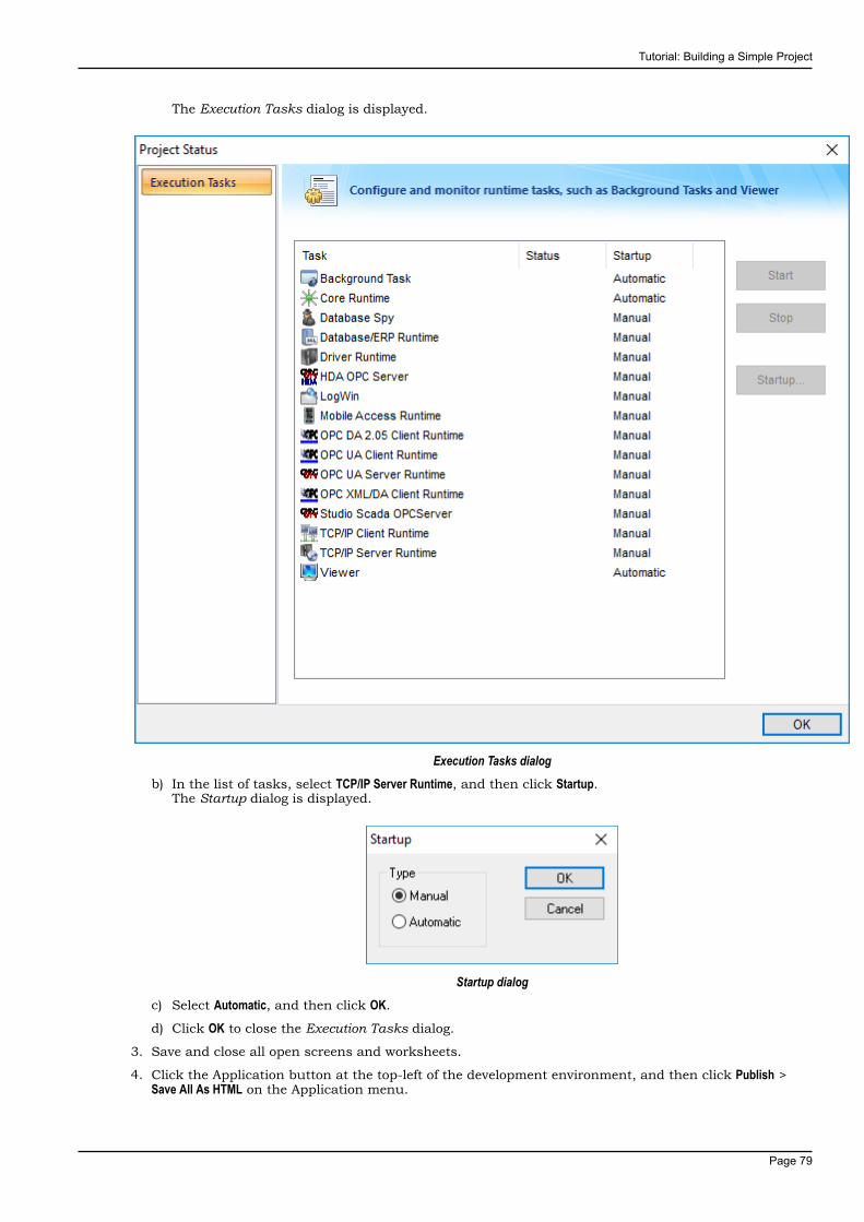
Tutorial: Building a Simple Project
Page 79
The Execution Tasks dialog is displayed.
Execution Tasks dialogb) In the list of tasks, select TCP/IP Server Runtime, and then click Startup.
The Startup dialog is displayed.
Startup dialogc) Select Automatic, and then click OK.
d) Click OK to close the Execution Tasks dialog.
3. Save and close all open screens and worksheets.
4. Click the Application button at the top-left of the development environment, and then click Publish >Save All As HTML on the Application menu.

Tutorial: Building a Simple Project
Page 80
Your project screens are saved as HTML files in the Web sub-folder of your project folder (i.e.,\<project name>\Web).
5. Configure a web server to make the Web sub-folder available to the network.For this tutorial, use NTWebServer, which is free, lightweight web server program that is included withthe InduSoft Web Studio software. Simply copy it from the InduSoft Web Studio program folder (atInduSoft Web Studio v8.1\Bin\NTWebServer.exe) to your project's Web sub-folder (at <projectname>\Web), and then double-click the file to run it. It automatically serves the contents of whateverfolder it is in, without any further configuration.
Note: NTWebServer is provided for testing purposes only. It should never be used in a realproduction environment or on a secure network.
You can also configure the "root directory" or "home directory" setting of some other web serverprogram (e.g., Microsoft IIS) to point to the Web sub-folder, or you can copy the Web sub-folder to anexisting web server on your network. The web server (which makes the HTML files available to clients)and the data server (which actually runs your IWS project and exchanges data with the clients) do notneed to be the same computer.
6. On the Home tab of the ribbon, in the Local Management group, click Run.
7. Open a web browser (e.g., Microsoft Internet Explorer), and then enter the URL address of the synopticscreen on the web server.For this tutorial, type http://127.0.0.1/synoptic.html and then press Return. (127.0.0.1 is thestandard IP address for the loopback network interface, a.k.a. "localhost".)After a few moments, during which the browser downloads and installs the browser plug-in, thesynoptic screen is displayed in the browser.
Notice that you can change the level of any tank either locally using the project viewer or remotely usingthe web browser, and changes on one client appear immediately on the other. They work equally well.