quasispherical fuel compression and fast ignition in a...
TRANSCRIPT

Quasispherical fuel compression and fast ignition in a heavy-ion-drivenX-target with one-sided illumination
Enrique Henestroza,1 B. Grant Logan,1 and L. John Perkins2
1Lawrence Berkeley National Laboratory, Berkeley, California 94720, USA2Lawrence Livermore National Laboratory, Livermore, California 94550, USA
�Received 16 November 2010; accepted 28 January 2011; published online 9 March 2011�
The HYDRA radiation-hydrodynamics code �M. M. Marinak et al., Phys. Plasmas 8, 2275 �2001��is used to explore one-sided axial target illumination with annular and solid-profile uranium ionbeams at 60 GeV to compress and ignite deuterium-tritium fuel filling the volume of metal caseswith cross sections in the shape of an “X” �X-target�. Quasi-three-dimensional, spherical fuelcompression of the fuel toward the X-vertex on axis is obtained by controlling the geometry of thecase, the timing, power, and radii of three annuli of ion beams for compression, and the hydroeffectsof those beams heating the case as well as the fuel. Scaling projections suggest that this target maybe capable of assembling large fuel masses resulting in high fusion yields at modest drive energies.Initial two-dimensional calculations have achieved fuel compression ratios of up to 150X soliddensity, with an areal density �R of about 1 g /cm2. At these currently modest fuel densities, fastignition pulses of 3 MJ, 60 GeV, 50 ps, and radius of 300 �m are injected through a hole in theX-case on axis to further heat the fuel to propagating burn conditions. The resulting burn waves areobserved to propagate throughout the tamped fuel mass, with fusion yields of about 300 MJ.Tamping is found to be important, but radiation drive to be unimportant, to the fuel compression.Rayleigh–Taylor instability mix is found to have a minor impact on ignition and subsequent fuelburn-up. © 2011 American Institute of Physics. �doi:10.1063/1.3563589�
I. INTRODUCTION
Fast ignition with heavy-ion beams has long been con-sidered for heavy-ion fusion.1–7 It would be desirable tominimize fuel compression energy using quasi-three-dimensional compression geometry, and use beam illumina-tion for both fuel compression and ignition from the sameside to simplify fusion chamber design as well as reducerequired beam bending from an accelerator driver to thechamber. To explore this goal, a simple axisymmetric targetwith deuterium-tritium �DT� filling a metal case with a crosssection in the shape of an X, called the “X-target” �Fig. 1�, isinvestigated using two-dimensional hydrodynamic implosioncalculations. A quasispherical pulsed-power target driven bya magnetic z-pinch has been considered with a similar crosssection but requires much higher fuel compressions and im-plosion velocities to enable central hot-spot ignition.8 Lowerfuel compression of large DT fuel mass ��1 g� has beenconsidered in the impact fusion scheme,9 which requires amuch larger beam energy �10–50 MJ�. Section II below de-scribes an initial X-target concept and the HYDRA codeused. Section III presents findings relating to four proof-of-principle questions for the X-target which motivated this pa-per. �a� To what degree can the X-target metal case shape,and the expansion of that case in regions where the beamspenetrate through it, help achieve quasi-three-dimensionalspherical fuel compression? �b� Does radiation �apart frombremsstrahlung losses� play an important role duringX-target fuel compression? �c� To what extent mightRayleigh–Taylor instabilities of the fuel-case interface causefuel-metal mixing affecting the ignition zone? �d� Assuminga step-wise pulse shaping in compression beam power, how
many power steps �successive shocks� are required toachieve the desired fuel densities for fast ignition in theX-target geometry?
For initial proof-of-principle, and to simplify the require-ments for an X-target accelerator driver, questions �a�–�d�above have been investigated assuming a single ion energyand mass �chosen to be 60 GeV U� for both fuel compressionand ignition. Different beam pulse durations incident on thetarget are assumed to be provided by different degrees ofdrift compression �different head-to-tail velocity ramps�vz /vz impressed on different beams drift compressing be-tween a multibeam accelerator and the target�; the ion energyof 60 GeV is in the middle of the range previously consid-ered for heavy-ion fast ignition.3 Potential accelerator driversto produce the X-target ion beams, and how such accelera-tors might provide the shorter pulses and smaller focal spotsneeded for fast ignition, are beyond the scope of this paper.However, Refs. 2–7 describe some driver and focusing ex-amples to consider. Provided suitable sources of high-charge-state heavy ions can be obtained, it can be noted that 60 GeVlinac drivers using U+12 ions would have comparable voltage�5 GV� and length ��3 km� as linac drivers with 4 GeVsingly charged heavy ions for indirect drive hohlraumtargets.10
As this paper is focused on the fundamental �proof-of-principle� questions stated above for the X-target concept,considerable future work is anticipated, to be partly de-scribed in Sec. IV where we discuss the one-dimensional�1D� compression requirements for higher peak density���100 g /cm3�, and in the conclusions, Sec. V.
PHYSICS OF PLASMAS 18, 032702 �2011�
1070-664X/2011/18�3�/032702/6/$30.00 © 2011 American Institute of Physics18, 032702-1
II. X-TARGET AND HYDRA CODE DESCRIPTION
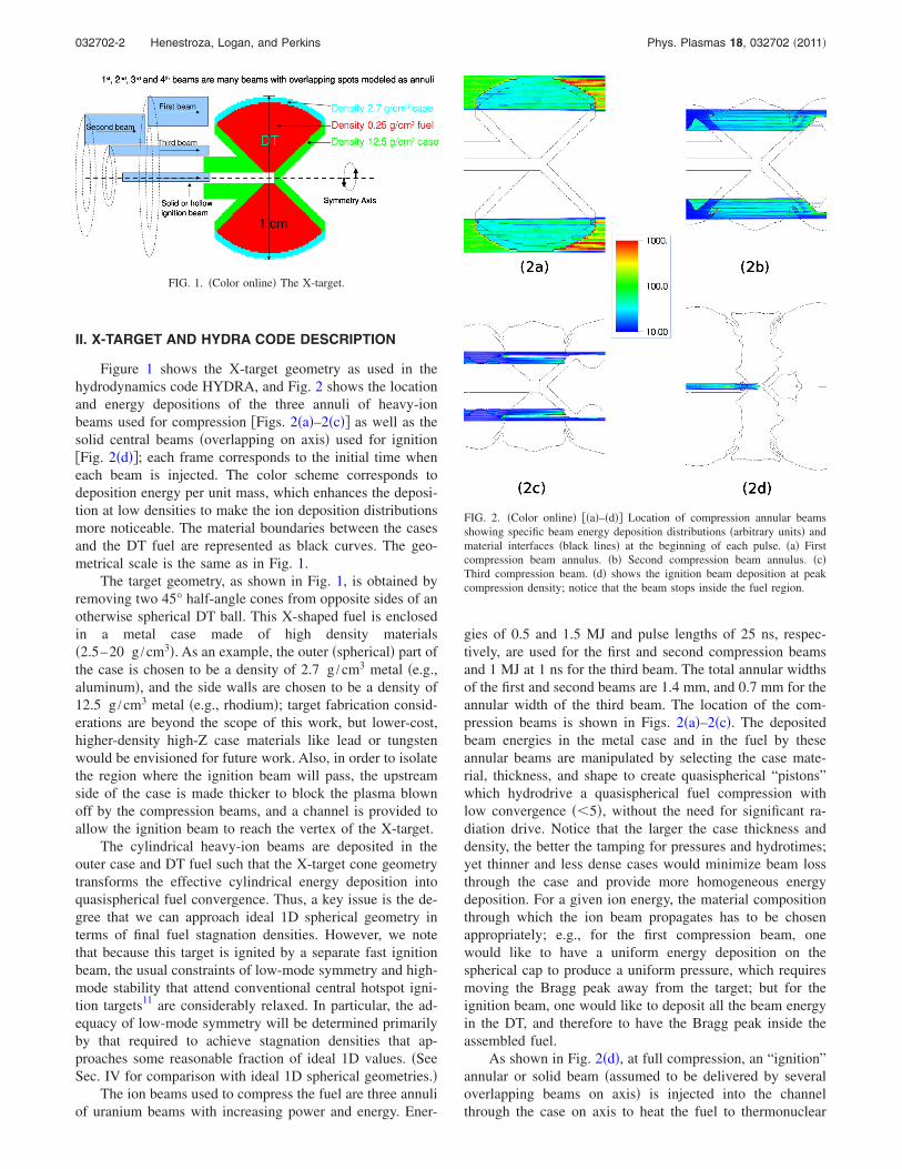
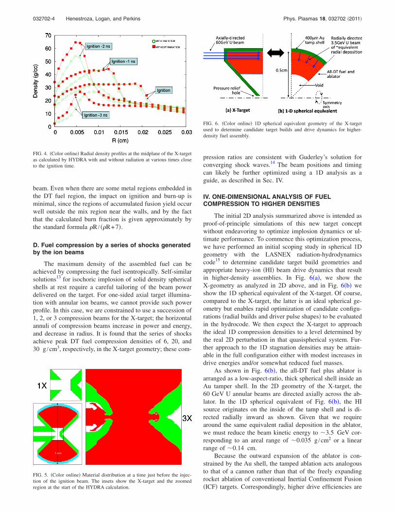
Figure 1 shows the X-target geometry as used in thehydrodynamics code HYDRA, and Fig. 2 shows the locationand energy depositions of the three annuli of heavy-ionbeams used for compression �Figs. 2�a�–2�c�� as well as thesolid central beams �overlapping on axis� used for ignition�Fig. 2�d��; each frame corresponds to the initial time wheneach beam is injected. The color scheme corresponds todeposition energy per unit mass, which enhances the deposi-tion at low densities to make the ion deposition distributionsmore noticeable. The material boundaries between the casesand the DT fuel are represented as black curves. The geo-metrical scale is the same as in Fig. 1.
The target geometry, as shown in Fig. 1, is obtained byremoving two 45° half-angle cones from opposite sides of anotherwise spherical DT ball. This X-shaped fuel is enclosedin a metal case made of high density materials�2.5–20 g /cm3�. As an example, the outer �spherical� part ofthe case is chosen to be a density of 2.7 g /cm3 metal �e.g.,aluminum�, and the side walls are chosen to be a density of12.5 g /cm3 metal �e.g., rhodium�; target fabrication consid-erations are beyond the scope of this work, but lower-cost,higher-density high-Z case materials like lead or tungstenwould be envisioned for future work. Also, in order to isolatethe region where the ignition beam will pass, the upstreamside of the case is made thicker to block the plasma blownoff by the compression beams, and a channel is provided toallow the ignition beam to reach the vertex of the X-target.
The cylindrical heavy-ion beams are deposited in theouter case and DT fuel such that the X-target cone geometrytransforms the effective cylindrical energy deposition intoquasispherical fuel convergence. Thus, a key issue is the de-gree that we can approach ideal 1D spherical geometry interms of final fuel stagnation densities. However, we notethat because this target is ignited by a separate fast ignitionbeam, the usual constraints of low-mode symmetry and high-mode stability that attend conventional central hotspot igni-tion targets11 are considerably relaxed. In particular, the ad-equacy of low-mode symmetry will be determined primarilyby that required to achieve stagnation densities that ap-proaches some reasonable fraction of ideal 1D values. �SeeSec. IV for comparison with ideal 1D spherical geometries.�
The ion beams used to compress the fuel are three annuliof uranium beams with increasing power and energy. Ener-
gies of 0.5 and 1.5 MJ and pulse lengths of 25 ns, respec-tively, are used for the first and second compression beamsand 1 MJ at 1 ns for the third beam. The total annular widthsof the first and second beams are 1.4 mm, and 0.7 mm for theannular width of the third beam. The location of the com-pression beams is shown in Figs. 2�a�–2�c�. The depositedbeam energies in the metal case and in the fuel by theseannular beams are manipulated by selecting the case mate-rial, thickness, and shape to create quasispherical “pistons”which hydrodrive a quasispherical fuel compression withlow convergence ��5�, without the need for significant ra-diation drive. Notice that the larger the case thickness anddensity, the better the tamping for pressures and hydrotimes;yet thinner and less dense cases would minimize beam lossthrough the case and provide more homogeneous energydeposition. For a given ion energy, the material compositionthrough which the ion beam propagates has to be chosenappropriately; e.g., for the first compression beam, onewould like to have a uniform energy deposition on thespherical cap to produce a uniform pressure, which requiresmoving the Bragg peak away from the target; but for theignition beam, one would like to deposit all the beam energyin the DT, and therefore to have the Bragg peak inside theassembled fuel.
As shown in Fig. 2�d�, at full compression, an “ignition”annular or solid beam �assumed to be delivered by severaloverlapping beams on axis� is injected into the channelthrough the case on axis to heat the fuel to thermonuclear
FIG. 2. �Color online� ��a�–�d�� Location of compression annular beamsshowing specific beam energy deposition distributions �arbitrary units� andmaterial interfaces �black lines� at the beginning of each pulse. �a� Firstcompression beam annulus. �b� Second compression beam annulus. �c�Third compression beam. �d� shows the ignition beam deposition at peakcompression density; notice that the beam stops inside the fuel region.
FIG. 1. �Color online� The X-target.
032702-2 Henestroza, Logan, and Perkins Phys. Plasmas 18, 032702 �2011�

conditions and start burn propagation. The energy of the ig-nition beam ranges between 1.0 and 3.0 MJ, the pulse lengthis 50–100 ps, and the beam radius is about 200 �m.HYDRA was used first to benchmark fast ignition calcula-tions of isolated spherical balls of DT at densities between 50and 300 g /cm3, with results similar to Refs. 4 and 5. Basedon these results, an ignition beam ion energy of 60 GeV waschosen as a compromise between fuel deposition energy andcoupling efficiency through the case. Furthermore, to mini-mize the complexity of accelerator drivers for X-targets,the ion energy of the compression beams is also chosen to be60 GeV.
Full radiation-hydrodynamics calculations includingthermonuclear burn were performed with the HYDRAcode.12 The state of the art code HYDRA is a single-fluid,multiblock, multimaterial arbitrary-Lagrange-Eulerianradiation-hydrodynamics code. It runs in either two-dimensional �2D� or three-dimensional �3D� on a block-structured mesh of arbitrary quadrilaterals or hexahedrons,respectively. HYDRA treats radiation transport with multi-group radiation diffusion or implicit Monte Carlo photonics.Flux-limited electron and ion heat conduction are available.Thermonuclear burn is treated, as is the transport and depo-sition of energetic charged particles produced by thermo-nuclear reactions.
The simulation effort was based on 2D �RZ� calculationsassuming axisymmetric target and annular and solid beams.Target fabrication errors and beam aiming errors can producesmall sources of 3D effects. 3D effects can also be producedby the fact that the annular beams may be composed of in-dividual solid beams located in a ring pattern, which breaksthe assumption of rotational symmetry. On the other hand,the fuel convergence is small, less than 7 in the X-target,which minimizes the effect of nonaxisymmetric features. 3Dsimulations using HYDRA are planned for the compressionphase to validate the assumption of cylindrical symmetryused here to treat the ring of ion beams as annular beams.
III. FINDINGS REGARDING THE BASIC PRINCIPLESOF THE X-TARGET CONCEPT
A. X-target metal case shape
The influence of the shape of the X-target case on thecompression dynamics can be seen by comparing the densityprofiles for two instances. Figures 3�a� and 3�c� show thetarget geometry and density maps before the first compres-sion beam is injected and Figs. 3�b� and 3�d� before theinjection of the second compression beam. Figures 3�a� and3�b� correspond to the case where the beam deposits its en-ergy only in the DT. A dramatic change is obtained by plac-ing a high density material in the beam path in such a waythat the beam will deposit a large amount of energy at theentrance and exit of the DT region generating two axial pis-tons which convert the cylindrical into a quasispherical pres-sure profile.
In a similar way, a spherical piston can be generated byreplacing the cylindrical cap in Fig. 3�c� by a spherical cap,as in the base case shown in Fig. 2�a�. The ion beam depositsa larger energy per unit volume in the metallic spherical cap
as compared to the energy per unit volume deposited in thelow-density DT, thereby producing a high pressure regionwith spherical symmetry which compresses the DT fuel.
The thickness of the side walls �the X� should be enoughto withstand the high pressure generated by the compressedfuel. Side walls of thickness less than 500 �m are observedto expand too rapidly to allow the DT fuel to be compressedquasispherically.
B. Radiation effects during X-target fuel compressionand ignition
The influence of radiation during the compression phasein the X-target is quite small since the ion temperatures reachvalues under 100 eV. It is only at the final stage of compres-sion �about 1 ns before the ignition beam is injected� that thetemperature increases to a couple of hundred electron volts.Figure 4 shows the snapshots of the radial density profiles atthe midplane of the X-target during the compression phaseand at various times, when radiation effects are turned onand off. Notice that the influence of radiation on the densityprofiles is minor, i.e., the hydrodynamics is dominant.
C. Rayleigh–Taylor mix
The degree to which the Rayleigh–Taylor instabilities ofthe fuel-case interface cause fuel-metal mixing in the igni-tion zone can be seen in Fig. 5, which shows the materialdistribution at a time just before the injection of the ignition
FIG. 3. �Color online� ��a�–�d�� Example of conversion of a cylindricalimplosion into a quasi-three-dimensional �hemispherical� convergent implo-sion. Density profiles �g /cm3� for �a� beam annulus going through caseopening, �b� a cylindrical shock is launched. �c� Beam annulus depositingenergy in the case, �d� a spherical shock is launched.
032702-3 Quasispherical fuel compression and fast ignition in a heavy-ion-driven X-target… Phys. Plasmas 18, 032702 �2011�
beam. Even when there are some metal regions embedded inthe DT fuel region, the impact on ignition and burn-up isminimal, since the regions of accumulated fusion yield occurwell outside the mix region near the walls, and by the factthat the calculated burn fraction is given approximately bythe standard formula �R / ��R+7�.
D. Fuel compression by a series of shocks generatedby the ion beams
The maximum density of the assembled fuel can beachieved by compressing the fuel isentropically. Self-similarsolutions13 for isochoric implosion of solid density sphericalshells at rest require a careful tailoring of the beam powerdelivered on the target. For one-sided axial target illumina-tion with annular ion beams, we cannot provide such powerprofile. In this case, we are constrained to use a succession of1, 2, or 3 compression beams for the X-target; the horizontalannuli of compression beams increase in power and energy,and decrease in radius. It is found that the series of shocksachieve peak DT fuel compression densities of 6, 20, and30 g /cm3, respectively, in the X-target geometry; these com-
pression ratios are consistent with Guderley’s solution forconverging shock waves.14 The beam positions and timingcan likely be further optimized using a 1D analysis as aguide, as described in Sec. IV.
IV. ONE-DIMENSIONAL ANALYSIS OF FUELCOMPRESSION TO HIGHER DENSITIES
The initial 2D analysis summarized above is intended asproof-of-principle simulations of this new target conceptwithout endeavoring to optimize implosion dynamics or ul-timate performance. To commence this optimization process,we have performed an initial scoping study in spherical 1Dgeometry with the LASNEX radiation-hydrodynamicscode15 to determine candidate target build geometries andappropriate heavy-ion �HI� beam drive dynamics that resultin higher-density assemblies. In Fig. 6�a�, we show theX-geometry as analyzed in 2D above, and in Fig. 6�b� weshow the 1D spherical equivalent of the X-target. Of course,compared to the X-target, the latter is an ideal spherical ge-ometry but enables rapid optimization of candidate configu-rations �radial builds and driver pulse shapes� to be evaluatedin the hydrocode. We then expect the X-target to approachthe ideal 1D compression densities to a level determined bythe real 2D perturbation in that quasispherical system. Fur-ther approach to the 1D stagnation densities may be attain-able in the full configuration either with modest increases indrive energies and/or somewhat reduced fuel masses.
As shown in Fig. 6�b�, the all-DT fuel plus ablator isarranged as a low-aspect-ratio, thick spherical shell inside anAu tamper shell. In the 2D geometry of the X-target, the60 GeV U annular beams are directed axially across the ab-lator. In the 1D spherical equivalent of Fig. 6�b�, the HIsource originates on the inside of the tamp shell and is di-rected radially inward as shown. Given that we requirearound the same equivalent radial deposition in the ablator,we must reduce the beam kinetic energy to �3.5 GeV cor-responding to an areal range of �0.035 g /cm2 or a linearrange of �0.14 cm.
Because the outward expansion of the ablator is con-strained by the Au shell, the tamped ablation acts analogousto that of a cannon rather than that of the freely expandingrocket ablation of conventional Inertial Confinement Fusion�ICF� targets. Correspondingly, higher drive efficiencies are
FIG. 4. �Color online� Radial density profiles at the midplane of the X-targetas calculated by HYDRA with and without radiation at various times closeto the ignition time.
FIG. 5. �Color online� Material distribution at a time just before the injec-tion of the ignition beam. The insets show the X-target and the zoomedregion at the start of the HYDRA calculation.
FIG. 6. �Color online� 1D spherical equivalent geometry of the X-targetused to determine candidate target builds and drive dynamics for higher-density fuel assembly.
032702-4 Henestroza, Logan, and Perkins Phys. Plasmas 18, 032702 �2011�

attainable. The thickness of the tamp shell �400 �m� is de-termined by the transit time of the pressure shock to the outersurface relative to the end of the HI drive pulse. As theX-target is configured with a pressure relief hole to enhancelate time convergence, we stipulate a void inside the fuelrather than the conventional 0.3 mg /cm3 equilibrium vaporpressure of solid DT fuel.
We then deduce the required radial build and HI drivedynamics by requiring �a� an ingoing fuel mass that wouldgive a fusion energy yield of 3 �1.5� GJ at a nominal burnfraction of 25%, �b� an ablator radial thickness of 0.14 cmcorresponding to a typical X-target annular beam thickness,�c� an initial fuel aspect ratio of 2.5 to provide good in-flightstability �low in-flight-aspect-ratio�, �d� an outer maximumdiameter of 1 cm, and �e� a total HI drive energy of 4�2� MJfor the fuel compression only. The corresponding fuel massis then 35.2 �17.6� mg, and the ratio of fuel, i.e., payload,mass to total initial mass is �0.3. �In this section where wequote extensive quantities, e.g., energies, masses, etc., thevalues in parentheses are those corresponding to an idealspherically converging X-target with a 45° half-angle, andare therefore 50% of those of the full-sphere values. Inten-sive quantities, e.g., densities, etc., are, by definition, thesame.�
The heavy-ion beam pulse shape for fuel assembly isshown in Fig. 7. The foot power of 8.2 �4.1� TW is set toprovide an average tamped ablation pressure of �1 Mbarover its duration, while the 300 �150� TW peak power andthe start of its rise is optimized to maximize the final as-sembled areal density ��R� of the fuel subject to the 4 �2� MJtotal energy constraint above. The intermediate power ped-estals are timed to synchronize shock breakout with the footshock on the inside of the fuel. This is a three-shock plusmain pulse shape. A four-shock plus main pulse shape canresult in �7% higher areal densities due to more precisetuning of the adiabat, while more than four initial pedestalsresult in little or no increased benefit to late time assembly.
Initial results are shown in Table I. Given the efficienttamped ablation drive, large fuel masses can potentially beassembled in this target platform. In particular, we note the
possibility for obtaining peak densities in excess of100 g /cm3 and assembled areal densities of �3.5 g /cm2
for fuel masses of �35�17� mg. If appropriately ignited witha separate fast ignition energy source, this offers the pros-pects for gigajoule fusion yields and target gains of several-hundreds at modest drive energies. As was described above,this happens in ideal spherical geometry but such densitiesshould be approachable in the full configuration either withmodest increases in drive energies and/or somewhat reducedfuel masses.
V. CONCLUSIONS
A succession of three horizontal annuli of compressionbeams at increasing powers and energies, and at decreasingradii, is found to be needed to achieve peak DT fuel com-pression densities of 6, 20, and 30 g /cm3, respectively, inthe X-target geometry. To reduce the required heavy-ionbeam ignition energy below the current level of 3 MJ at peakdensity of 30 g /cm3, work in progress is seeking to achievefuel densities of �100 g /cm3 �fuel convergence increasesfrom 5 to �7� and with improved beam-into-fuel couplingefficiencies �from currently low levels of 20% to above40%�. As indicated in Sec. IV, 1D implosion analysis sug-gests at least one additional compression drive pulse mightbe needed to reach peak ��100 g /cm3, one more than thethree used in this report.
The results presented here are intended as initial ex-amples reaching sufficient fuel compression ��200X solidDT� to provide a proof-of-principle for this novel fuel assem-bly and heavy-ion drive geometry. Already, these X-targetresults give target performance comparable to that of indirectdrive heavy-ion targets.10 The X-target design is far fromoptimized and many further improvements can be envi-sioned. The results of these first examples give confidencethat by careful tailoring of all the available parameters, DTfuel with a density of �50 g /cm3 and �r�2 g /cm2 shouldbe achievable. If so, this target platform should be capable ofassembling large fuel masses resulting in high fusion yieldsat modest heavy-ion drive energies.
FIG. 7. �Color online� Heavy-ion pulse shape for fuel assembly. The totalenergy and peak powers are 4 �2� MJ and 300 �150� TW, respectively, for afull �half� sphere.
TABLE I. Results of initial LASNEX fuel assembly simulations in 1Dspherical geometry. The values in parentheses for extensive quantities arethose corresponding to an ideal spherically converging X-target with a 45°half-angle, which is 50% of the full-sphere values.
Fuel mass 35.2 �17.6� mg
Fuel inner radius and radial thickness 0.24 cm, 0.120 cm
Ablator radial thickness 0.140 cm
Heavy-ion drive energy for compression 4 �2� MJ
Peak drive power 300 �150� TW
Maximum areal density �-R 3.38 g /cm2
Peak fuel density at max �-R 101 g /cm3
Average fuel density at max �-Ra 83.3 g /cm3
Approximate projected fusion yieldb �3.8�1.9� GJ
aDensity radially averaged over the shell between the 1/e of peak densitypoints.bYield of this assembled fuel mass assuming an appropriate ignition sourceand a burn fraction of ��R / ��R+7�.
032702-5 Quasispherical fuel compression and fast ignition in a heavy-ion-driven X-target… Phys. Plasmas 18, 032702 �2011�
In particular, improvements can be expected in the beamdeposition and coupling efficiency into DT by optimizing theion kinetic energy together with the X-target case thick-nesses. The third compression beam annulus, as well as us-ing hollow ignition beams,16,17 might be explored withhigher power levels at shorter pulses of a few hundred pico-seconds, attempting to shock compress densities of20 g /cm3 at the end of the second compression pulse to�100 g /cm3 before the final ignition pulse. The shape of theignition beam �solid to hollow�, consisting of several over-lapping individual beam spots, and focused in a more con-vergent geometry, might be further optimized together withthe shape of the fuel at stagnation and with the shape of asemicavity hydroformed into the compressed case near thevertex to reduce ignition energy and lengthen ignition pulsesto more than 100 ps.
Burn waves �Tion�15 keV� have already been observedin this work to begin propagating radially outward into thelower density regions of the X-target, much like the asym-metric hemispherical target proposed by Nuckolls18 for gain1000. To the extent future work succeeds in achieving higher� and �r�2 g /cm2, a much larger fusion yield contributionfrom burn waves propagating into the outer low-density fuelregion of the X-target may lead to lower drive energy, largerfusion yields of 1–2 GJ, and much higher gains.
ACKNOWLEDGMENTS
This work was in part inspired by discussions with BorisSharkov �the application of axisymmetric beam annular com-pression drive exploiting beam spot rotation using R. F.“wobblers”� and by discussions with John Nuckolls �encour-aging the exploration of fast ignition of lower density fuelassemblies for higher gain using heavy-ion beams�.
This work was performed under the support of the U.S.
Department of Energy by the Lawrence Berkeley NationalLaboratory under Contract No. DE-AC02-05CH11231 andthe Lawrence Livermore National Laboratory under ContractNo. DE-AC52-07NA27344.
1A. W. Maschke, Proceedings of the 1975 IEEE Particle Accelerator Con-ference, 1975, p. 1875; IEEE Report No. NS-22, June 1975.
2M. Tabak, J. Hammer, M. E. Glinsky, W. L. Kruer, S. C. Wilks, J.Woodworth, E. M. Campbell, M. D. Perry, and R. J. Mason, Phys. Plas-mas 1, 1626 �1994�.
3M. Tabak and D. A. Callahan-Miller, Proceedings of the 12th InternationalSymposium on Heavy Ion Inertial Fusion, Heidelberg, Germany, 24–27September 1997; �Nucl. Instrum. Methods Phys. Res. A 415, 75 �1998��.
4M. Temporal, J. J. Honrubia, and S. Atzeni, Phys. Plasmas 9, 3098�2002�.
5S. A. Medin, M. D. Churazov, D. G. Koshkarev, B. Yu. Sharkov, Yu. N.Orlov, and V. M. Suslin, Laser Part. Beams 20, 419 �2002�.
6B. G. Logan, R. O. Bangerter, D. A. Callahan, M. Tabak, M. Roth, L. J.Perkins, and G. Caporaso, Fusion Sci. Technol. 49, 399 �2006�.
7D. A. Callahan-Miller and M. Tabak, Phys. Plasmas 7, 2083 �2000�.8T. Nash, P. VanDevender, N. Roderick, and D. McDaniel, Sandia NationalLaboratories Report No. SAND2007-7178, November 2007.
9S. Kawata and T. Saitoh, Proceedings of the Tenth International Confer-ence on High Power Particle Beams, 1994, p. 179.
10S. S. Yu, W. R. Meier, R. P. Abbott, J. J. Barnard, T. Brown, D. A.Callahan, C. Debonnel, P. Heitzenroeder, J. F. Latkowski, B. G. Logan, S.J. Pemberton, P. F. Peterson, D. V. Rose, G.-L. Sabbi, W. M. Sharp, and D.R. Welch, Fusion Sci. Technol. 44, 266 �2003�.
11J. Lindl, Phys. Plasmas 2, 3933 �1995�.12M. M. Marinak, G. D. Kerbel, N. A. Gentile, O. Jones, D. Munro, S.
Pollaine, T. R. Dittrich, and S. W. Haan, Phys. Plasmas 8, 2275 �2001�.13D. S. Clark and M. Tabak, Nucl. Fusion 47, 1147 �2007�.14G. Guderley, Luftfahrtforschung 19, 302 �1942�.15G. B. Zimmerman and W. L. Kruer, Comments Plasma Phys. Controlled
Fusion 2, 51 �1975�.16M. Herrmann, S. Hatchett, and M. Tabak, Bull. Am. Phys. Soc. 46, 106
�2001�.17M. Temporal, R. Ramis, J. J. Honrubia, and S. Atzeni, Plasma Phys. Con-
trolled Fusion 51, 035010 �2009�.18J. H. Nuckolls, J. Phys.: Conf. Ser. 244, 012007 �2010�.
032702-6 Henestroza, Logan, and Perkins Phys. Plasmas 18, 032702 �2011�