quality control manual - xrqa.comxrqa.com/downloads/mammography/siemens novation qa...
TRANSCRIPT

Quality Control ManualMAMMOMAT Novation DR

The original version of this operator manual was written in the Ger-man language.
CONFIDENTIALITY STATEMENT
This document ist the confidential property of Siemens AG MedicalSolutions.No part of it may be transmitted, reproduced, published, or used byother persons without the permission of Siemens AG MedicalSolutions.

MAMMOMAT Novation DR
SPB7-250.623.02.04.02
Do you have any comments on this operator manual?
Your opinion matters a lot to us! 0
We make every effort to continuously improve our product documentation. Therefore we would like to offer you the opportunity to give us your requests, suggestions and criticism with respect to this operator manual directly.
o For feedback by fax, please use the following fax number:+49 9131/84-2378
o If you prefer notification by e-mail, please send this to:[email protected]
In this case we request you to use as reference the complete print number in the footer of this page.
Thank you very much for supporting us in our efforts to improve our products.
My notes
Optional information
Name
Hospital
City/country
Phone/fax
Number of fax pages


Table of Contents
MAMMOMAT Novation DR 1SPB7-250.623.02.04.02
Table of Contents
List of tables
List of figures
List of common abbreviations
IntroductionMammography Equipment Evaluation (MEE) - Medical physicist (MP)................................. 13Annually or every six months - Medical physicist (MP) ......................................................... 13Weekly - Technologist (T) ...................................................................................................... 13When needed - Technologist (T)............................................................................................ 13Recommended frequency of QC tests.................................................................................. 14Important notes ..................................................................................................................... 15Recommended corrective action........................................................................................... 15Documents required.............................................................................................................. 15Equipment required ............................................................................................................... 16
Startup and loginStarting the system from the off state .................................................................................. 17Starting the system from standby mode............................................................................... 17
Performing an examinationProcedure .............................................................................................................................. 18
PrerequisitesObjective ............................................................................................................................... 20Equipment required ............................................................................................................... 20Procedure .............................................................................................................................. 20Performance criteria and corrective action ............................................................................ 20
Test 1: Clinical settingsObjective ............................................................................................................................... 21Procedure .............................................................................................................................. 21
Test 2: Mechanical inspection and follow-upObjective ............................................................................................................................... 22Equipment required ............................................................................................................... 22Procedure .............................................................................................................................. 22Performance criteria and corrective action ............................................................................ 24
Test 3: CompressionObjective ............................................................................................................................... 25Equipment required ............................................................................................................... 25Procedure .............................................................................................................................. 25Performance criteria and corrective action ............................................................................ 26
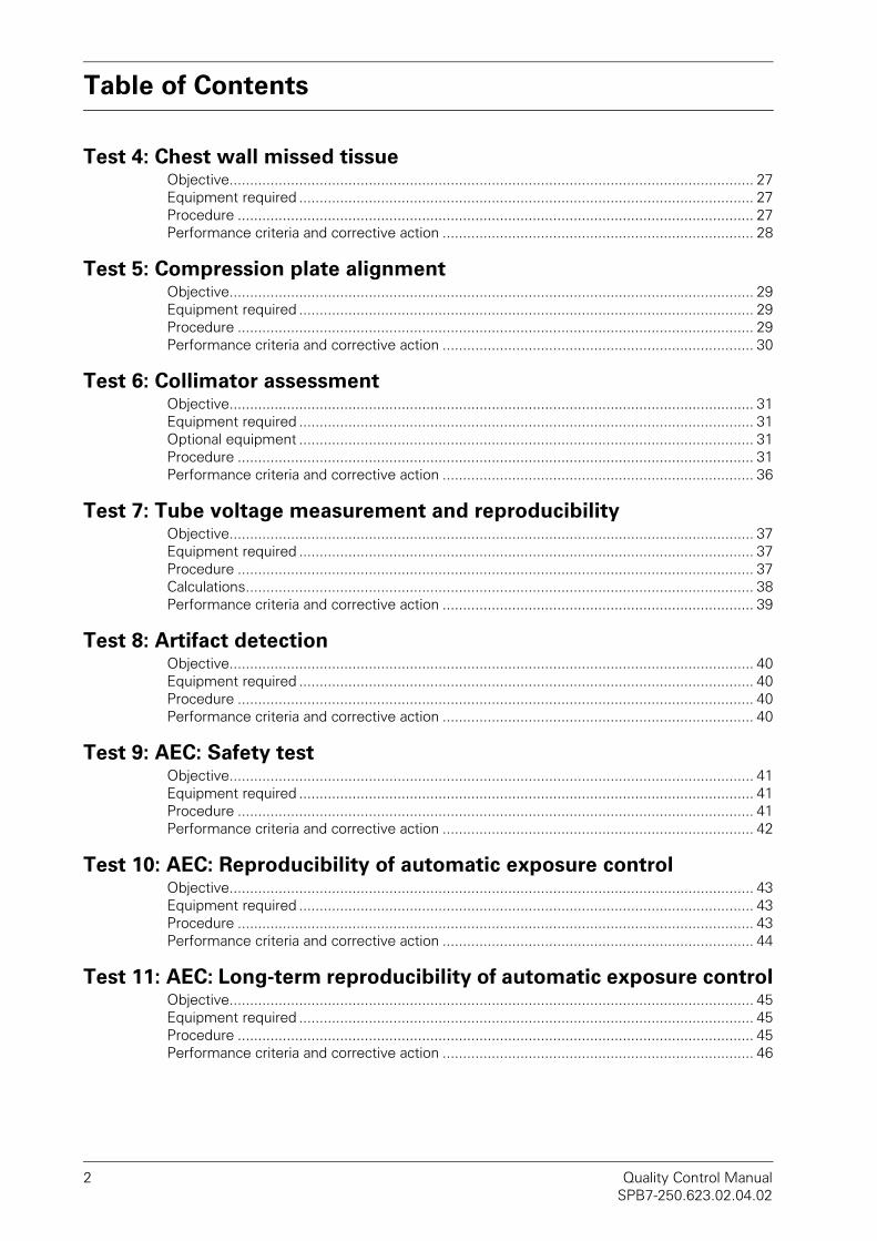
Table of Contents
2 Quality Control ManualSPB7-250.623.02.04.02
Test 4: Chest wall missed tissueObjective................................................................................................................................ 27Equipment required ............................................................................................................... 27Procedure .............................................................................................................................. 27Performance criteria and corrective action ............................................................................ 28
Test 5: Compression plate alignmentObjective................................................................................................................................ 29Equipment required ............................................................................................................... 29Procedure .............................................................................................................................. 29Performance criteria and corrective action ............................................................................ 30
Test 6: Collimator assessmentObjective................................................................................................................................ 31Equipment required ............................................................................................................... 31Optional equipment ............................................................................................................... 31Procedure .............................................................................................................................. 31Performance criteria and corrective action ............................................................................ 36
Test 7: Tube voltage measurement and reproducibilityObjective................................................................................................................................ 37Equipment required ............................................................................................................... 37Procedure .............................................................................................................................. 37Calculations............................................................................................................................ 38Performance criteria and corrective action ............................................................................ 39
Test 8: Artifact detectionObjective................................................................................................................................ 40Equipment required ............................................................................................................... 40Procedure .............................................................................................................................. 40Performance criteria and corrective action ............................................................................ 40
Test 9: AEC: Safety testObjective................................................................................................................................ 41Equipment required ............................................................................................................... 41Procedure .............................................................................................................................. 41Performance criteria and corrective action ............................................................................ 42
Test 10: AEC: Reproducibility of automatic exposure controlObjective................................................................................................................................ 43Equipment required ............................................................................................................... 43Procedure .............................................................................................................................. 43Performance criteria and corrective action ............................................................................ 44
Test 11: AEC: Long-term reproducibility of automatic exposure controlObjective................................................................................................................................ 45Equipment required ............................................................................................................... 45Procedure .............................................................................................................................. 45Performance criteria and corrective action ............................................................................ 46

Table of Contents
MAMMOMAT Novation DR 3SPB7-250.623.02.04.02
Test 12: AEC: Tracking testObjective ............................................................................................................................... 47Equipment required ............................................................................................................... 47Procedure .............................................................................................................................. 47Performance criteria and corrective action ............................................................................ 48
Test 13: Linearity and noise evaluationObjective ............................................................................................................................... 49Equipment required ............................................................................................................... 49Procedure .............................................................................................................................. 49Performance criteria and corrective action ............................................................................ 51
Test 14: Detector uniformityObjective ............................................................................................................................... 52Equipment required ............................................................................................................... 52Procedure .............................................................................................................................. 52Performance criteria and corrective action ............................................................................ 53
Test 15: Phantom image qualityObjective ............................................................................................................................... 54Equipment required ............................................................................................................... 54Procedure .............................................................................................................................. 54Analysis ................................................................................................................................. 56Performance criteria and corrective action ............................................................................ 56
Test 16: Phantom image quality – Maximum resolutionObjective ............................................................................................................................... 57Equipment required ............................................................................................................... 57Procedure .............................................................................................................................. 57Performance criteria and corrective action ............................................................................ 58
Test 17: Mean glandular doseObjective ............................................................................................................................... 59Equipment required ............................................................................................................... 59Requirements ........................................................................................................................ 59Procedure .............................................................................................................................. 59Performance criteria and corrective action ............................................................................ 60
Test 18: Ghost image evaluationObjective ............................................................................................................................... 61Equipment required ............................................................................................................... 61Requirements ........................................................................................................................ 61Procedure .............................................................................................................................. 61Performance criteria and corrective action ............................................................................ 63
Test 19: AWS monitor checkObjective ............................................................................................................................... 64Equipment required ............................................................................................................... 64Procedure .............................................................................................................................. 64Performance criteria and corrective action ............................................................................ 66

Table of Contents
4 Quality Control ManualSPB7-250.623.02.04.02
Test 20: Printer checkObjective................................................................................................................................ 67Equipment required ............................................................................................................... 67Procedure .............................................................................................................................. 67Performance criteria and corrective action ............................................................................ 67
Appendix 1 – Test formsTest form Test 1: Clinical settings..........................................................................71Test form Test 2: Mechanical inspection and follow-up ........................................73
Mechanical inspection and follow-up..................................................................................... 74
Test form Test 3: Compression .............................................................................75Compression.......................................................................................................................... 76
Test form Test 4: Chest wall missed tissue...........................................................77Chest wall missed tissue....................................................................................................... 77
Test form Test 5: Compression plate alignment....................................................79Compression plate overlap .................................................................................................... 79
Test form Test 6: Collimator assessment ..............................................................81
Test form Test 7: Tube voltage measurement and reproducibility ........................85Tube voltage and reproducibility ............................................................................................ 86
Test form Test 8: Artifact detection.......................................................................87Clinically relevant artifacts ..................................................................................................... 87
Test form Test 9: AEC: Safety test ........................................................................89AEC: Safety test .................................................................................................................... 89
Test form Test 10: AEC: Reproducibility of automatic exposure control ...............91AEC: Reproducibility of automatic exposure control ............................................................. 92
Test form Test 11: AEC: Long-term reproducibility of automatic exposure control ....................................................................................................................93
AEC: Long-term reproducibility of automatic exposure control ............................................. 93
Test form Test 12: AEC: Tracking test ...................................................................95Object thickness and tube voltage compensation................................................................. 95
Test form Test 13: Linearity and noise evaluation .................................................97Linearity ................................................................................................................................. 98Noise evaluation .................................................................................................................... 99
Test form Test 14: Detector uniformity ...............................................................101Detector uniformity.............................................................................................................. 102Results from ROI statistics.................................................................................................. 102
Test form Test 15: Phantom image quality ..........................................................103Contrast resolution .............................................................................................................. 103
Test form Test 16: Phantom image quality – Maximum resolution .....................105Resolution............................................................................................................................ 105
Test form Test 17: Mean glandular dose .............................................................107Mean glandular dose ........................................................................................................... 109
Test form Test 18: Ghost image evaluation .........................................................111Ghost image evaluation ....................................................................................................... 112

Table of Contents
MAMMOMAT Novation DR 5SPB7-250.623.02.04.02
Test form Test 19: AWS monitor check .............................................................. 113AWS monitor check and viewing conditions ....................................................................... 113
Test form Test 20: Printer check ......................................................................... 115
Appendix 2 – Test forms for installation
Test form Test 1: Clinical settings ....................................................................... 121
Test form Test 2: Mechanical inspection and follow-up ...................................... 123Mechanical inspection and follow-up................................................................................... 124
Test form Test 3: Compression ........................................................................... 125Compression ....................................................................................................................... 126
Test form Test 4: Chest wall missed tissue ........................................................ 127Chest wall missed tissue..................................................................................................... 127
Test form Test 5: Compression plate alignment ................................................. 129Compression plate overlap .................................................................................................. 129
Test form Test 6: Collimator assessment............................................................ 131
Test form Test 8: Artifact detection..................................................................... 135Clinically relevant artifacts ................................................................................................... 135
Test form Test 11: AEC: Long-term reproducibility of automatic exposure control.................................................................................................................. 137
AEC: Long-term reproducibility of automatic exposure control ........................................... 137
Test form Test 12: AEC: Tracking test................................................................. 139Object thickness and tube voltage compensation............................................................... 139
Test form Test 13: Linearity and noise evaluation ............................................... 141Linearity ............................................................................................................................... 142Noise evaluation .................................................................................................................. 143
Test form Test 14: Detector uniformity ............................................................... 145Detector uniformity ............................................................................................................. 146Results from ROI statistics.................................................................................................. 146
Test form Test 15: Phantom image quality.......................................................... 147Contrast resolution .............................................................................................................. 147
Test form Test 16: Phantom image quality – Maximum resolution ..................... 149Resolution............................................................................................................................ 149
Test form Test 17: Mean glandular dose............................................................. 151Mean glandular dose ........................................................................................................... 153
Test form Test 18: Ghost image evaluation......................................................... 155Ghost image evaluation ....................................................................................................... 156
Test form Test 19: AWS monitor check .............................................................. 157AWS monitor check and viewing conditions ....................................................................... 157
Test form Test 20: Printer check ......................................................................... 159

Table of Contents
6 Quality Control ManualSPB7-250.623.02.04.02

Tables
MAMMOMAT Novation DR 7SPB7-250.623.02.04.02
List of tables
Table 1 Frequency of tests .................................................................................... 14Table 2 Object score criteria.................................................................................. 56

Tables
8 Quality Control ManualSPB7-250.623.02.04.02
Figures
MAMMOMAT Novation DR 9SPB7-250.623.02.04.02
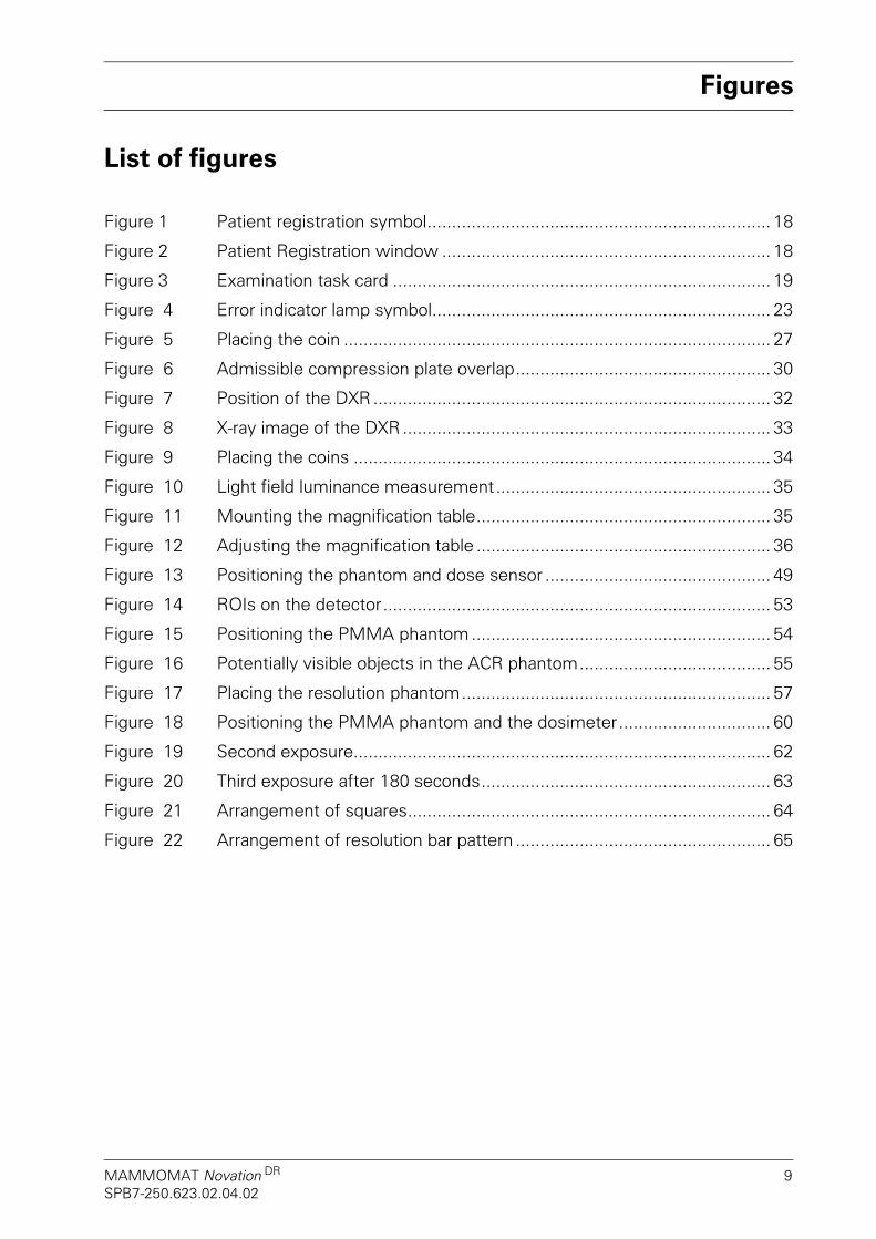
List of figures
Figure 1 Patient registration symbol...................................................................... 18
Figure 2 Patient Registration window ................................................................... 18
Figure 3 Examination task card ............................................................................. 19
Figure 4 Error indicator lamp symbol..................................................................... 23
Figure 5 Placing the coin ....................................................................................... 27
Figure 6 Admissible compression plate overlap.................................................... 30
Figure 7 Position of the DXR................................................................................. 32
Figure 8 X-ray image of the DXR........................................................................... 33
Figure 9 Placing the coins ..................................................................................... 34
Figure 10 Light field luminance measurement........................................................ 35
Figure 11 Mounting the magnification table............................................................ 35
Figure 12 Adjusting the magnification table ............................................................ 36
Figure 13 Positioning the phantom and dose sensor .............................................. 49
Figure 14 ROIs on the detector............................................................................... 53
Figure 15 Positioning the PMMA phantom ............................................................. 54
Figure 16 Potentially visible objects in the ACR phantom....................................... 55
Figure 17 Placing the resolution phantom............................................................... 57
Figure 18 Positioning the PMMA phantom and the dosimeter............................... 60
Figure 19 Second exposure..................................................................................... 62
Figure 20 Third exposure after 180 seconds........................................................... 63
Figure 21 Arrangement of squares.......................................................................... 64
Figure 22 Arrangement of resolution bar pattern .................................................... 65

Figures
10 Quality Control ManualSPB7-250.623.02.04.02

Abbreviations
MAMMOMAT Novation DR 11SPB7-250.623.02.04.02
List of common abbreviations
AEC Automatic Exposure Control
AEC D Button AEC Detail Mode Button
AEC H Button AEC Low Dose Button
AWS Acquisition Workstation
CNR Contrast-to-Noise Ratio
FD Flat Detector
FFDM Full-Field Digital Mammography
HVL Half Value Layer
mAs Milliampere/second
MEE Mammography Equipment Evaluation
Mo/Mo Molybdenum/Molybdenum
Mo/Rh Molybdenum/Rhodium
MP Medical Physicist
PMMA Polymethylmethacrylate
ROI Region Of Interest
SID Source-Image Distance
SMPTE Society of Motion Picture and Television Engineers
SNR Signal-to-Noise Ratio
SP Special Systems
T Technologist = user
W/Rh Tungsten/Rhodium

Abbreviations
12 Quality Control ManualSPB7-250.623.02.04.02
For notes
Introduction
MAMMOMAT Novation DR 13SPB7-250.623.02.04.02
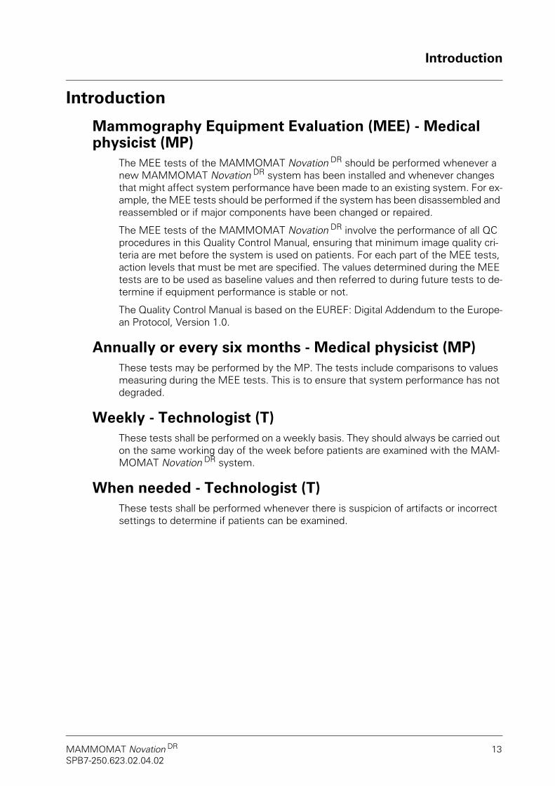
Introduction
Mammography Equipment Evaluation (MEE) - Medical physicist (MP)
The MEE tests of the MAMMOMAT Novation DR should be performed whenever a new MAMMOMAT Novation DR system has been installed and whenever changes that might affect system performance have been made to an existing system. For ex-ample, the MEE tests should be performed if the system has been disassembled and reassembled or if major components have been changed or repaired.
The MEE tests of the MAMMOMAT Novation DR involve the performance of all QC procedures in this Quality Control Manual, ensuring that minimum image quality cri-teria are met before the system is used on patients. For each part of the MEE tests, action levels that must be met are specified. The values determined during the MEE tests are to be used as baseline values and then referred to during future tests to de-termine if equipment performance is stable or not.
The Quality Control Manual is based on the EUREF: Digital Addendum to the Europe-an Protocol, Version 1.0.
Annually or every six months - Medical physicist (MP)These tests may be performed by the MP. The tests include comparisons to values measuring during the MEE tests. This is to ensure that system performance has not degraded.
Weekly - Technologist (T)These tests shall be performed on a weekly basis. They should always be carried out on the same working day of the week before patients are examined with the MAM-MOMAT Novation DR system.
When needed - Technologist (T)These tests shall be performed whenever there is suspicion of artifacts or incorrect settings to determine if patients can be examined.
Introduction
14 Quality control manualSPB7-250.623.02.04.02
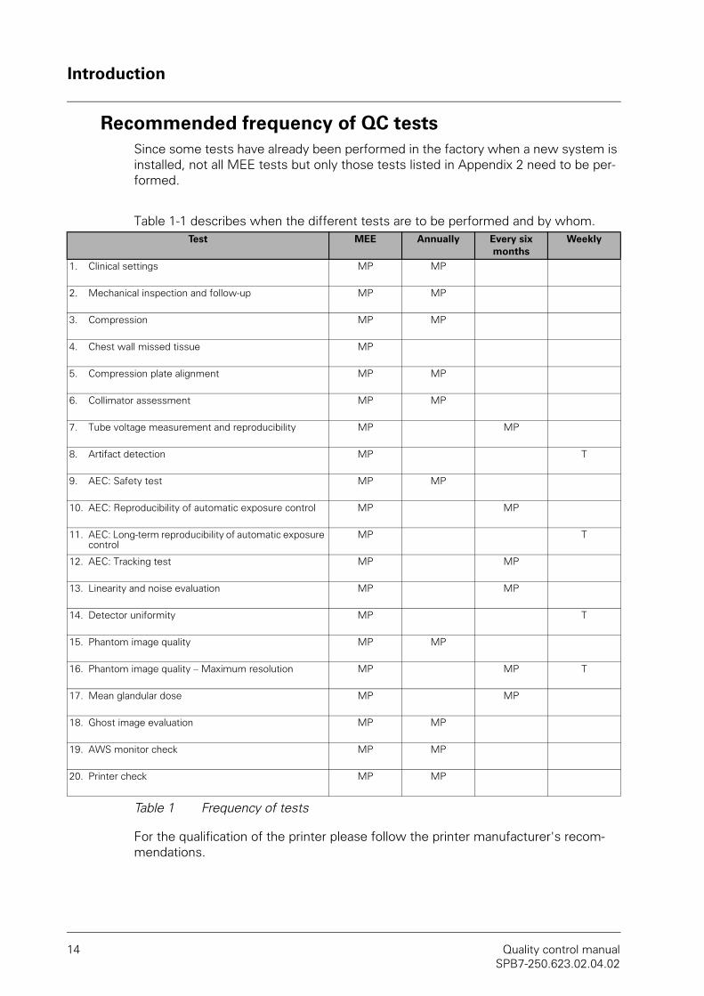
Recommended frequency of QC testsSince some tests have already been performed in the factory when a new system is installed, not all MEE tests but only those tests listed in Appendix 2 need to be per-formed.
Table 1-1 describes when the different tests are to be performed and by whom.
Table 1 Frequency of tests
For the qualification of the printer please follow the printer manufacturer's recom-mendations.
Test MEE Annually Every six months
Weekly
1. Clinical settings MP MP
2. Mechanical inspection and follow-up MP MP
3. Compression MP MP
4. Chest wall missed tissue MP
5. Compression plate alignment MP MP
6. Collimator assessment MP MP
7. Tube voltage measurement and reproducibility MP MP
8. Artifact detection MP T
9. AEC: Safety test MP MP
10. AEC: Reproducibility of automatic exposure control MP MP
11. AEC: Long-term reproducibility of automatic exposure control
MP T
12. AEC: Tracking test MP MP
13. Linearity and noise evaluation MP MP
14. Detector uniformity MP T
15. Phantom image quality MP MP
16. Phantom image quality – Maximum resolution MP MP T
17. Mean glandular dose MP MP
18. Ghost image evaluation MP MP
19. AWS monitor check MP MP
20. Printer check MP MP
Introduction
MAMMOMAT Novation DR 15SPB7-250.623.02.04.02
Important notesBefore performing any quality control tests, make sure you are thoroughly familiar with the Operator Manual for MAMMOMAT Novation DR.
The test parameters used and the test results obtained can be entered in the en-closed test form tables (Appendix).
Recommended corrective actionIf the result of a test described in this manual fails to meet the action level specified, the problem must be determined and corrected before further examinations are per-formed with the system. The result shall be reported to a service engineer and appro-priate corrective action shall be taken to address the problem.
If a result meets the action level, but there is a clear degradation compared to the re-sult obtained during the previous test, the system may continue to be used, but the degradation shall be reported to a service engineer. It is recommended that corrective action be taken within 30 days.
More detailed information can be found at the end of each test description.
Documents required• MAMMOMAT Novation DR Operator Manual
• syngo MammoReport Quality Control Manual (optional - for systems that use a softcopy reporting station)

Introduction
16 Quality control manualSPB7-250.623.02.04.02
Equipment requiredThe test equipment listed below must always display a valid calibration stamp. Ensure compliance with the described measurement and calibration intervals.
• Mammography line pair phantom (2 to 10 lp/mm)
• PMMA phantom that attaches to the collimator (40 mm thick)*
• Three PMMA phantoms 100 x 100 mm, (each 20 mm thick)*
• PMMA phantom 100 x 100 mm, (10 mm thick)*
• Lint-free, non-woven cotton or gauze (100% cotton)
• Water or lukewarm diluted aqueous solution of household dishwashing liquid
• Illuminance meter
• Densitometer
• Non-invasive digital kV meter
• Dosimeter, calibrated at the anode/filter combinations used
• Film or CR cassette, 24 x 30 cm or larger
• Magnification table (optional)
• Compression plate simulator**
• 2 mm steel plate (FD object table size)*
• 2 mm steel plate (3 x 10 cm)*
• Six sheets of 99.9% pure aluminum, (0.1 mm thick)
• Six coins
• Timer (stop watch)
• Ruler with millimeter scale
• RMI-156 phantom (ACR phantom)
• Foam rubber or other compressible phantom
• Compression plate 24 x 30 cm ***
• Unfors DXR+ X-ray ruler (optional)
* Provided with every system.
** Provided with every system. Allows exposures to be performed without compression plate attached.
*** If not available, you may also use a different plate (except spot compression plate) that is suitable for Opcomp operation

Startup and login
MAMMOMAT Novation DR 17SPB7-250.623.02.04.02
Startup and loginThe MAMMOMAT Novation DR system can be started either from the off state (i.e. from being completely shut down) or from standby mode.
Starting the system from the off state
CAUTION!Incorrect operation can lead to image quality losses.
Allow the MAMMOMAT Novation DR to warm up for at least 60 min-utes to ensure optimal results during the image quality test or calibra-tion.
1. Switch the main power switch in the room on.
2. Wait approx. 5 minutes.
3. Press the On button on the control console to enable the MAMMOMAT Novation
DR.The internal monitoring system automatically performs a functional test of the MAMMOMAT Novation DR.
4. Wait until “DR” is displayed on the control console.
5. Switch on the workstation and the monitor at the acquisition workstation.
6. Log in at the workstation.
7. Allow the MAMMOMAT Novation DR to warm up for at least 60 minutes to obtain optimum image quality.
Starting the system from standby mode1. Press the On button on the control console to enable the
MAMMOMAT Novation DR.
2. Wait until “DR” is displayed on the control console.
3. Switch on the workstation and the monitor at the acquisition workstation, if they are switched off. The workstation boots up.
4. To ensure optimum image quality, allow the MAMMOMAT Novation DR to warm up for at least 5 minutes. The internal monitoring system automatically performs a functional test of the MAMMOMAT Novation DR."dr" is displayed on the film density display on the control panel to indicate that the communication with the MAMMOMAT Novation DR system is functioning.
5. Log in at the workstation.
NOTE!NOTE!The room must be equipped with a dimmer switch to dim the light in the room when necessary.

Performing an examination
18 Quality control manualSPB7-250.623.02.04.02
Performing an examinationProcedure
1. Log in observing the safety information in the Startup and login section.
Figure 1 Patient registration symbol
2. Click the button shown.The Patient Registration window opens.
Figure 2 Patient Registration window

Performing an examination
MAMMOMAT Novation DR 19SPB7-250.623.02.04.02
3. Enter the required examination data.
4. Click the Exam button.This will take you back to the Examination task card.
Figure 3 Examination task card
5. Select the Procedure required for your examination from the selection list (1). The projection sequence preset for the procedure is displayed in the PAO selec-tion list.
6. The projection views (2) to be performed are displayed as buttons on the Images subtask card according to their sequence.
7. The exposure is release by double-clicking the first projection view on the Imag-es subtask card.
8. Position the swivel arm of the MAMMOMAT according to the first required pro-jection view.
9. Position the phantom on the object table according to the view selected at the acquisition workstation.
10. Release the exposure. To do this, keep both exposure release buttons on the control console pressed until the acoustic signal has sounded and stopped.Radiation is released and the first image is acquired.At the end of the exposure the acquired image is displayed in the image area.
NOTE!NOTE!The radiation indicator may light up only when the exposure release button is pressed. Observe radiation protective measures.
1
2

Prerequisites
20 Quality control manualSPB7-250.623.02.04.02
Prerequisites
ObjectiveTo determine if the detector is damaged or dusty and has been calibrated.
Equipment requireda) Lint-free, non-woven cotton or gauze (100% cotton)
b) Water or lukewarm diluted aqueous solution of household dishwashing liquid
Procedure1. Wipe the detector surface with a wet lint-free non-woven cotton cloth or cotton
pad (100% cotton). For moistening, use water or a lukewarm diluted aqueous so-lution of household dishwashing liquid.
NOTE!NOTE!Do not spray the unit! The cleaning fluid must under no circumstances penetrate into the unit.
2. Calibrate the detector according to the chapter Calibrating the detector in the MAMMOMAT Novation DR Operator Manual. When doing so, use the main an-ode/filter combination typically used in clinical practice (see Test 1: Clinical set-tings).
Performance criteria and corrective actionThere must be no visible damage.
No artifacts must be visible on the calibration images.
Test 1: Clinical settings
MAMMOMAT Novation DR 21SPB7-250.623.02.04.02
Test 1: Clinical settings
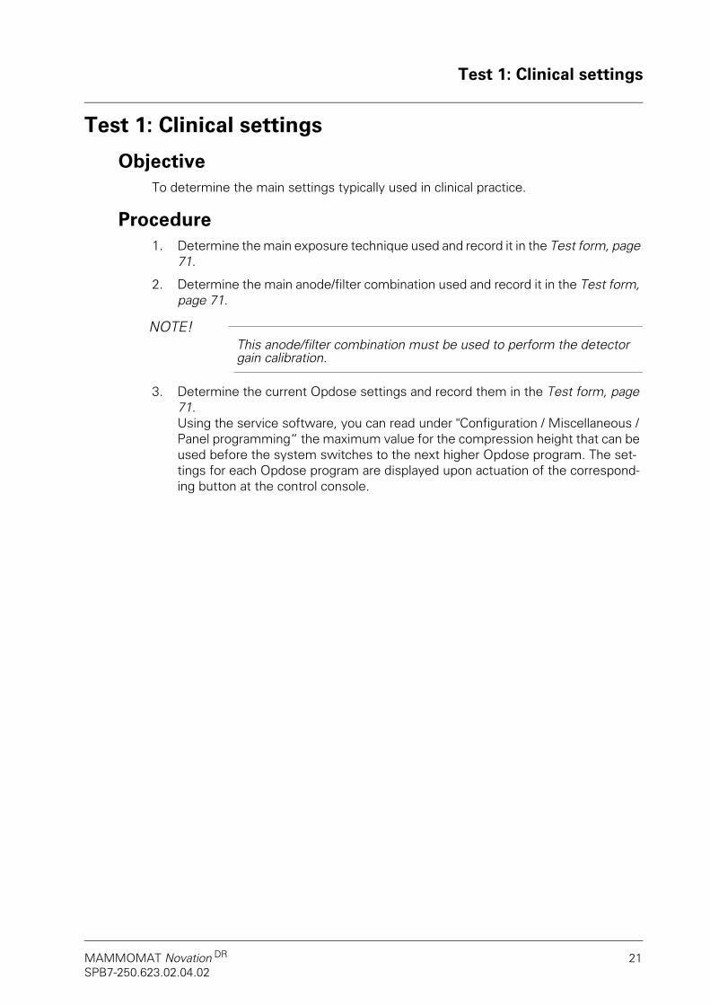
Objective To determine the main settings typically used in clinical practice.
Procedure 1. Determine the main exposure technique used and record it in the Test form, page
71.
2. Determine the main anode/filter combination used and record it in the Test form, page 71.
NOTE!NOTE!This anode/filter combination must be used to perform the detector gain calibration.
3. Determine the current Opdose settings and record them in the Test form, page 71.Using the service software, you can read under "Configuration / Miscellaneous / Panel programming“ the maximum value for the compression height that can be used before the system switches to the next higher Opdose program. The set-tings for each Opdose program are displayed upon actuation of the correspond-ing button at the control console.

Test 2: Mechanical inspection and follow-up
22 Quality control manualSPB7-250.623.02.04.02
Test 2: Mechanical inspection and follow-up
ObjectiveMEE:
• To ensure that the system is mechanically intact and all displays on the con-trol panel and stand are functioning properly.
Annual test:
• To ensure that the system is mechanically intact and all displays on the con-trol panel and stand are functioning properly.
• To look for trends in the results of all non-annual tests.
Equipment requiredMEE:
a) Compression plate 24 x 30
Annual test:
a) Test reports of the daily tests
b) Compression plate 24 x 30
Procedure1. Check that there is no visible damage to the cables. Record the result in the Test
form, page 73.
2. Check that the control panel lights up, indicating that the power is switched on. Record the result in the Test form, page 73.

Test 2: Mechanical inspection and follow-up
MAMMOMAT Novation DR 23SPB7-250.623.02.04.02
3. Turn the swivel arm 180° so that the tube head is straight upside down. Lower the system as close to the floor as possible. Check that the error indicator lamp (see Figure 4) is lit. Raise the system again, turn the swivel arm back and check that the lamp goes out. Record the result in the Test form, page 73.
Figure 4 Error indicator lamp symbol
4. Check that motorized movements are performed smoothly and properly. Record the result in the Test form, page 73.
5. Check that the height adjustment and rotation of the swivel arm system are dis-abled when the displayed compression force is ≥ 3 kp. Record the result in the Test form, page 73.
6. Perform a functional check of the EMERGENCY STOP button. Note that with the button depressed all motorized movements must be disabled. Record the result in the Test form, page 73.
7. Check that manual compression/decompression functions properly. Record the result in the Test form, page 73.
8. Check that the decompression button on the control console functions correctly. Record the result in the Test form, page 73.
9. There must be no sharp edges or cracks that could create sharp edges on the compression plates, the detector, etc. which could injure the patient. Record the result in the Test form, page 73.
10. The edges of the radiation shield must be clearly defined so that operating staff is aware of the outline. Record the result in the Test form, page 73.
11. The focal spot position must be clearly marked by the red dot on the tube assem-bly. Record the result in the Test form, page 73.
12. Motorized vertical movement must be possible even with the patient leaning against the breast support platform (without compression applied). Record the result in the Test form, page 73.
13. All foot switches must function properly. Record the result in the Test form, page 73.
14. All attachments must latch securely and their locks must function effectively. Record the result in the Test form, page 73.
Test 2: Mechanical inspection and follow-up
24 Quality control manualSPB7-250.623.02.04.02
Performance criteria and corrective action
Annual test: Follow-up checks
The daily test charts must be inspected. Look for trends, deviations, etc.
If these charts indicate a decrease in image quality over time, the physicist should compare these results with the tests he/she has performed himself/herself. If a level has degraded over time but is still within the action levels specified in this document, the system may continue to be used, but the degradation must be reported to a Sie-mens customer service engineer. In addition, it is recommended that the system be recalibrated.
If any of the specified performance criteria is not fulfilled, the cause of the prob-lem must be identified and the problem must be corrected by a Siemens cus-tomer service engineer. The criterion must then be successfully retested by the MP before further examinations are performed with the system.

Test 3: Compression
MAMMOMAT Novation DR 25SPB7-250.623.02.04.02
Test 3: Compression
ObjectiveTo ensure that the compression device functions properly
Equipment requireda) Foam rubber or other compressible phantom
b) Compression plate 24 x 30
c) PMMA phantom (2 x 20 mm plexi PMMA)
Procedure1. Create a new patient record in the local database.
Fill in: Last Name: Test_ThreeFirst Name: CompressionPatient ID: Day+time when the test is performed
(Example: 200411281350)DOB: 05 05 1955Sex: Other
2. Choose the "FD QC Raw" procedure.
3. Select Opdose program 3 on the control panel.
4. Place the foam rubber on the FD object table.
5. Mount the compression plate.
6. Run the compression plate against the FD object table and compress the phan-tom beyond the Opcomp threshold until compression stops. Record the value shown on the display of the stand base in the Test form, page 75.
7. Wait 1 minute and then record the displayed value in the Test form, page 75.
8. Activate automatic decompression on the control panel and make an exposure.
9. Check that the compression plate moves up at the end of the exposure and record the result in the Test form, page 75.
10. Remove the foam rubber and place the PMMA phantom (40 mm) on the object table.
11. Compress with a force of approx. 7 kp.
12. Deactivate automatic decompression on the control panel and make an expo-sure.

Test 3: Compression
26 Quality control manualSPB7-250.623.02.04.02
13. Check that the compression plate does not move up at the end of the exposure and record the result in the Test form, page 75.
14. Read the displayed thickness off the image and record it in the Test form, page 75.
15. Close the patient by clicking the Close patient button.
Performance criteria and corrective action
Annual test: Follow-up checks
The maximum adjustable force must be 19 - 21 kp.The adjustable force must not vary by more than 2 kp within one minute.Activation and deactivation of automatic decompression must function properly.The compression height must be displayed in the image with an accuracy of ± 3 mm.
If any of the specified performance criteria is not fulfilled, the cause of the prob-lem must be identified and the problem must be corrected by a Siemens cus-tomer service engineer. The criterion must then be successfully retested by the MP before further examinations are performed with the system.

Test 4: Chest wall missed tissue
MAMMOMAT Novation DR 27SPB7-250.623.02.04.02
Test 4: Chest wall missed tissue
ObjectiveTo ensure that the chest wall dead space is within a tolerance range of max. 5 mm.
Equipment requireda) Coin
b) Compression plate simulator
Procedure1. Create a new patient record in the local database.
Fill in: Last Name: Test_FourFirst Name: Chest Wall Missed TissuePatient ID: Day+time when the test is performed
(Example: 200411281350)DOB: 05 05 1955Sex: Other
2. Choose the "FD QC Raw" procedure.
3. Place the coin on the FD object table so that its edge is exactly tangent to the chest wall edge of the FD object table. See Figure 5.
Figure 5 Placing the coin
4. Mount the compression plate simulator.
5. Make an exposure with 28 kV, 50 mAs, Mo/Mo.
6. Using the measuring tool of the AWS, measure the diameter of the coin and the distance from the rear coin edge to the front detector edge. Record the values in the Test form, page 77.
7. Close the patient by clicking the Close patient button.
< 5
mm
Detector
CoinChest wall edge
Carbonfibercover

Test 4: Chest wall missed tissue
28 Quality control manualSPB7-250.623.02.04.02
Performance criteria and corrective actionThe distance should be less than or equal to 5 mm.
If any of the specified performance criteria is not fulfilled, the cause of the prob-lem must be identified and the problem must be corrected by a Siemens cus-tomer service engineer. The criterion must then be successfully retested by the MP before further examinations are performed with the system.

Test 5: Compression plate alignment
MAMMOMAT Novation DR 29SPB7-250.623.02.04.02
Test 5: Compression plate alignment
ObjectiveTo ensure that the position of the chest wall side of each compression plate allows for complete imaging of chest wall tissues.
Equipment requireda) All compression plates delivered with the unit
b) Ruler
c) PMMA phantom 2 x 20 mm
Procedure1. Create a new patient record in the local database.
Fill in: Last Name: Test_FiveFirst Name: Compression Plate AlignmentPatient ID: Day+time when the test is performed
(Example: 200411281350)DOB: 05 05 1955Sex: Other
2. Mount a compression plate.
3. Measure the overlapping distance from the chest wall edge of the compression plate to the edge of the object table on the chest wall side.The distance must be measured in the middle of the compression plate.
4. Add to the measured value the value a from Test 4: Chest wall missed tissue and record it in the Test form, page 79.
5. Place the PMMA phantom (40 mm) centrally on the detector, flush with the front edge.
6. Compress to approx. 7 kp.
7. Make an exposure with 28 kV, 40 mAs, Mo/Mo.
8. Check if the chest wall edge of the compression plate is visible in the image.
9. Repeat steps 2 through 6 for the remaining compression plates.
Test 5: Compression plate alignment
30 Quality control manualSPB7-250.623.02.04.02
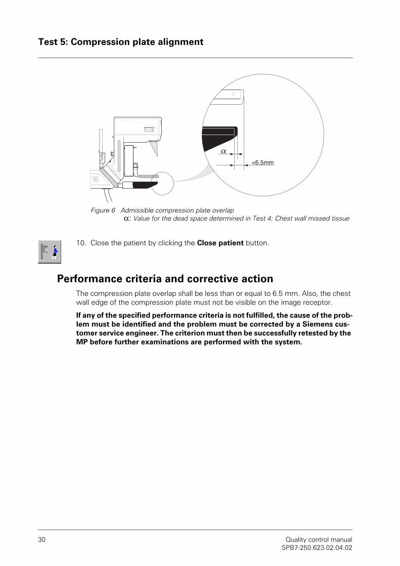
Figure 6 Admissible compression plate overlapα: Value for the dead space determined in Test 4: Chest wall missed tissue
10. Close the patient by clicking the Close patient button.
Performance criteria and corrective actionThe compression plate overlap shall be less than or equal to 6.5 mm. Also, the chest wall edge of the compression plate must not be visible on the image receptor.
If any of the specified performance criteria is not fulfilled, the cause of the prob-lem must be identified and the problem must be corrected by a Siemens cus-tomer service engineer. The criterion must then be successfully retested by the MP before further examinations are performed with the system.
<6.5mm
a

Test 6: Collimator assessment
MAMMOMAT Novation DR 31SPB7-250.623.02.04.02
Test 6: Collimator assessment
ObjectiveTo ensure that the collimator does not allow significant radiation beyond the edges of the image detector.
Equipment requiredThe test can be performed in two different ways:
a) With X-ray ruler:
• Unfors DXR+ X-ray ruler
• Compression plate simulator
• Illuminance meter
b) With film or CR cassette This variant requires a film processor for the X-ray film.
• Six coins
• Ruler
• Film or CR cassette
• Compression plate simulator
• Illuminance meter
Optional equipmenta) Magnification table
Procedure1. Create a new patient record in the local database.
Fill in: Last Name: Test_SixFirst Name: Collimator AssessmentPatient ID: Day+time when the test is performed
(Example: 200411281350)DOB: 05 05 1955Sex: Other
2. Choose the "FD QC Raw" procedure.
3. Make sure that the compression plate simulator is mounted.
4. Swivel the X-ray tube into the 0° position.
With X-ray ruler (steps 5 - 11)
5. Place the DXR according to Figure 7 position 1 (arrow labeled "X-ray" on the DXR must point to the center of the detector)

Test 6: Collimator assessment
32 Quality control manualSPB7-250.623.02.04.02
Figure 7 Position of the DXR
6. Activate the light field. Align the red line on the DXR with the edge of the light field. Enter the value 0 in the "Value light field“ column in the Test form, page 81.
7. Make an exposure with 35 kV, 100 mAs, Mo/Mo.
8. View the display on the DXR and record the value next to the last visible digit on the scale in the "Value radiation field“ column in the Test form, page 81 (last digit shows the edge of the radiation field).
9. View the image on the workstation. Change the window levels until the scale in the DXR is visible, see Figure 8. Record the last visible number at the end of the active area in the "Value detector field“ column in the Test form, page 81 (scale indicates the edge of the active detector area).

Test 6: Collimator assessment
MAMMOMAT Novation DR 33SPB7-250.623.02.04.02
Figure 8 X-ray image of the DXR
10. Repeat steps 5 to 9 on all four edges of the detector Figure 7 Position 2 to 4.
11. Repeat steps 5 to 10 with W/Rh.
With film or CR cassette (steps 12 - 20)
12. Place a film or CR cassette (24 x 30 or larger) on top of the FD-object table and turn it so that the mid-points of the light field edges are within the film/cassette dimensions; see Figure 9.
13. Press the light field button. Place four coins on the film / the CR cassette as mark-ers on the mid-point of each light field edge. The edges of the coins must be tan-gent to the outer light field edges. See Figure 9. Place two additional coins for orientation!
End of active area
Edge of light field
X-ray scale
Last visible number

Test 6: Collimator assessment
34 Quality control manualSPB7-250.623.02.04.02
Figure 9 Placing the coins
14. Make an exposure with 28 kV, 40 mAs, Mo/Mo.
15. Develop the film or CR cassette and mark it with the anode/filter combination used.
16. Using a ruler, measure the distance e on the developed film / the CR cassette for each coin, see Figure 9, and record the value in the "Value light field“ column in the Test form, page 81. Also measure the distance f and record the value in the "Value radiation field“ column in the Test form, page 81.
17. Measure for each coin the distance g on the monitor of the acquisition worksta-tion see Figure 9, and record the value in the "Value detector field“ column in the Test form, page 81.
a
b
g
f
e
Film cassetteLight field
Radiation field
Image receptor area / detector

Test 6: Collimator assessment
MAMMOMAT Novation DR 35SPB7-250.623.02.04.02
18. Repeat steps 12 - 17 with W/Rh.
19. Close the patient by clicking the Close patient button.
20. Perform the calculation according to the test form and check the values.
21. Use an illuminance meter to measure the light intensity of the radiation field on the object table in the four areas specified in Figure 10. Record the result in the Test form, page 81.
Figure 10 Light field luminance measurement
Test with magnification table (optional equipment)
22. Mount the magnification table by placing the table forks into the slots (see Posi-tion 1, Figure 11) on both sides of the FD object table and slide it in.
Figure 11 Mounting the magnification table
Light field
1 2
34
1

Test 6: Collimator assessment
36 Quality control manualSPB7-250.623.02.04.02
23. Slide the magnification carbon fiber top into the lower compartment for magnifi-cation factor 1.5 (see Figure 12).
Figure 12 Adjusting the magnification table
24. Create a new patient record in the local database.Fill in: Last Name: Test_Six_Mag
First Name: Collimator AssessmentPatient ID: Day+time when the test is performed
(Example: 200411281350)DOB: 05 05 1955Sex: Other
25. Repeat the test from step 2 using one of the two procedures (X-ray ruler/film or CR cassette). Step 21 is inapplicable.
Performance criteria and corrective action• The total radiation field/light field misalignment (sum of misalignments on op-
posite sides) shall not exceed 2% of the SID (13 mm).
• The radiation field shall not extend beyond any edge of the image receptor by more than 2% of the SID (13 mm). Note that this value is a maximum overlap for individual sides and no summing of opposite sides shall be made in this case.
• The mean value of the light intensity shall be more or equal to 160 lux.
If any of these tests fail, the cause must be identified and the problem must be corrected before further examinations are performed with the system. The result must be reported to a service engineer. In addition, appropriate cor-rective action shall be taken to address the problem. After the problem has been corrected, a medical physicist or technologist must conduct the test again to confirm that the problem has indeed been corrected.
Magnification factor 1.5

Test 7: Tube voltage measurement and reproducibility
MAMMOMAT Novation DR 37SPB7-250.623.02.04.02
Test 7: Tube voltage measurement and reproducibility
ObjectiveCheck that the accuracy of the displayed tube voltage value complies with the speci-fications.
Equipment requireda) Calibrated, non-invasive digital kV meter
b) Compression plate simulator
c) 2 mm steel plate (object table size)
Procedure1. Create a new patient record in the local database.
Fill in: Last Name: Test_SevenFirst Name: Tube VoltagePatient ID: Day+time when the test is performed
(Example: 200411281350)DOB: 05 05 1955Sex: Other
2. Choose the "FD QC Raw" procedure.
3. Ensure that the Mammomat system was switched on at least 15 minutes before the test is performed.
4. Mount the compression plate simulator.
5. Place the 2 mm steel plate on the detector.
NOTE!NOTE!The 2 mm steel plate must cover the detector during the entire length of the test. Otherwise, detector saturation or ghosting will occur.
Test 7: Tube voltage measurement and reproducibility
38 Quality control manualSPB7-250.623.02.04.02
6. Place the kV sensor on top of the steel plate, 40 mm from the chest wall side and centered.
7. Take four successive exposures with the following setting: 28 kV, 50 mAs and Mo/Mo.Enter the kV value for the tube voltage measured with the kV meter into the Test form, page 85.
8. Take four exposures with the following settings: 24/27/30/33 kV, each exposure with 50mAs and Mo/Mo.Enter the kV value for the tube voltage measured with the kV meter into the Test form, page 85.
9. Close the patient by clicking the Close patient button.
NOTE!NOTE!Note that these measurements must be performed consecutively and must be completed within an hour.
Calculations1. Check that the accuracy of the measured kV values for the different kV settings
is within ± 1.0 kV of the corresponding nominal value.
2. Calculate the mean value for the tube voltage at 28 kV:
kVi = Measured value from measurement i
3. Check that the measured kV value is within ± 0.5 kV of the kV-mean value:
(kVmean– 0.5 kV) ≤ kVmeas ≤ (kVmean+ 0.5 kV)
kVmeankV1 kV2 kV3 kV4+ + +
4---------------------------------------------------------------------------=

Test 7: Tube voltage measurement and reproducibility
MAMMOMAT Novation DR 39SPB7-250.623.02.04.02
Performance criteria and corrective actionAccuracy: The measured tube voltage value shall not deviate by more
than ± 1.0 kV from the selected nominal value.
Reproducibility: The measured tube voltage value shall not deviate by more than ± 0.5 kV from the mean value.
If any of the specified performance criteria is not fulfilled, the cause of the prob-lem must be identified and the problem must be corrected by a Siemens cus-tomer service engineer. The criterion must then be successfully retested by the MP before further examinations are performed with the system.
Test 8: Artifact detection
40 Quality control manualSPB7-250.623.02.04.02
Test 8: Artifact detectionObjective
To determine if the detector is dusty or damaged or shows other artifacts.
Equipment requireda) PMMA phantom that mounts to the collimator (40 mm)
b) Compression plate simulator
Procedure1. Create a new patient record in the local database.
Fill in: Last Name: Test_EightFirst Name: Artifact_DetectionPatient ID: Day+time when the test is performed
(Example: 200411281350)DOB: 05 05 1955Sex: Other
2. Choose the "FD QC Raw" procedure.
3. Mount the compression plate simulator.
4. Attach the PMMA phantom (40 mm) to the collimator.
5. Make an exposure with 28 kV, 90 mAs. Use the anode/filter combination that was used in the system calibration, see Test 1: Clinical settings
6. Check the image for clinically relevant artifacts; if necessary, send the image to the viewing station for evaluation.
Performance criteria and corrective actionThere should be no clinically relevant artifacts visible in the image.
If any of the specified performance criteria is not fulfilled, the cause of the prob-lem must be identified and the problem must be corrected by a Siemens cus-tomer service engineer. The criterion must then be successfully retested by the MP before further examinations are performed with the system.

Test 9: AEC: Safety test
MAMMOMAT Novation DR 41SPB7-250.623.02.04.02
Test 9: AEC: Safety test
ObjectiveTo check that the AEC safety cut-off functions properly.
Equipment requireda) 2 mm steel plate (object table size)
b) Compression plate 24 x 30
Procedure1. Create a new patient record in the local database.
Fill in: Last Name: Test_NineFirst Name: AEC: SafetyPatient ID: Day+time when the test is performed
(Example: 200411281350)DOB: 05 05 1955Sex: Other
2. Choose the "FD QC Raw" procedure.
3. Mount the compression plate.
4. Place the 2 mm steel plate on the breast support surface.
NOTE!NOTE!The 2 mm steel plate must cover the detector during the entire length of the test. Otherwise, detector saturation or ghosting will occur.
5. Select the AEC exposure H button, 28 kV, Mo/Mo.
6. Take an exposure.
7. Check that the exposure is interrupted.
8. Record the error number displayed on the control panel in the Test form, page 89.
9. Close the patient by clicking the Close patient button.

Test 9: AEC: Safety test
42 Quality control manualSPB7-250.623.02.04.02
Performance criteria and corrective actionThe AEC safety cut-off must function properly. The AEC- exposure must be interrupt-ed.Error 504, 578 or 579 must be displayed on the control panel.
If any of the specified performance criteria is not fulfilled, the cause of the prob-lem must be identified and the problem must be corrected by a Siemens cus-tomer service engineer. The criterion must then be successfully retested by the MP before further examinations are performed with the system.
Test 10: AEC: Reproducibility of automatic exposure control
MAMMOMAT Novation DR 43SPB7-250.623.02.04.02
Test 10: AEC: Reproducibility of automatic exposure control
ObjectiveTo measure the AEC image stability (reproducibility)
Equipment requireda) PMMA phantom 2 x 20 mm and 1 x 10 mm
b) Compression plate 24 x 30
Procedure1. Create a new patient record in the local database.
Fill in: Last Name: Test_TenFirst Name: AEC: Short-term ReproPatient ID: Day+time when the test is performed
(Example: 200411281350)DOB: 05 05 1955Sex: Other
2. Choose the "FD QC Raw" procedure.
3. Mount the compression plate.
4. Place the PMMA phantom (50 mm) on the detector so that all three sensor areas are covered.
5. Using the markings on the compression plate, check that the PMMA phantom covers all three AEC regions.
6. Select the Opdose program for 50 mm on the control panel (default: program 3, see Test 1: Clinical settings) and record the set parameters in the Test form, page 91.
7. Make an exposure and record the mAs value displayed on the console in the Test form, page 91.
8. Select a ROI (region of interest) of approx. 10 x 10 mm for postprocessing with Tools > Rectangle and position it within the AEC region used (the AEC region can be displayed by selecting Tools > AEC Region) and record the displayed mean value in the Test form, page 91.
Test 10: AEC: Reproducibility of automatic exposure control
44 Quality control manualSPB7-250.623.02.04.02
9. Repeat steps 7 and 8 until you have made 5 exposures.
10. Close the patient by clicking the Close patient button.
11. Calculate the mean value of the displayed mean pixel values and the mAs values displayed on the console and record them in the relevant column in the Test form, page 91.
12. Calculate the deviation of each value from the calculated mean value:
and record the maximum deviation in the relevant column in the Test form, page 91.
Performance criteria and corrective actionThe maximum deviation from the calculated mean value must be ≤ 5%.
If any of the specified performance criteria is not fulfilled, the cause of the prob-lem must be identified and the problem must be corrected by a Siemens cus-tomer service engineer. The criterion must then be successfully retested by the MP before further examinations are performed with the system.
ValueMean value---------------------------------------- 1–⎝ ⎠⎛ ⎞ 100%⋅

Test 11: AEC: Long-term reproducibility of automatic exposure control
MAMMOMAT Novation DR 45SPB7-250.623.02.04.02
Test 11: AEC: Long-term reproducibility of automatic exposure control
ObjectiveTo measure the AEC image stability (long-term reproducibility)
Equipment requireda) PMMA phantom 2 x 20 mm and 1 x 10 mm
b) Compression plate 24 x 30
Procedure1. Create a new patient record in the local database.
Fill in: Last Name: Test_ElevenFirst Name: AEC: Long-term ReproPatient ID: Day+time when the test is performed
(Example: 200411281350)DOB: 05 05 1955Sex: Other
2. Choose the "FD QC Raw" procedure.
3. Mount the compression plate.
4. Place the PMMA phantom (50 mm) on the detector so that all three sensor areas are covered.
5. Using the markings on the compression plate, check that the PMMA phantom covers all three AEC regions.
6. Select the Opdose program for 50 mm on the control panel (default: program 3, see Test 1: Clinical settings) and record the set parameters in the Test form, page 93.
7. Make an exposure and record the mAs value displayed on the console in the Test form, page 93.
8. Select a ROI (region of interest) of approx. 10 x 10 mm for postprocessing with Tools > Rectangle and position it within the AEC region used (the AEC region can be displayed by selecting Tools > AEC Region) and record the displayed mean pixel value in the Test form, page 93.
9. Close the patient by clicking the Close patient button.

Test 11: AEC: Long-term reproducibility of automatic exposure control
46 Quality control manualSPB7-250.623.02.04.02
Performance criteria and corrective actionThe mean pixel value must not deviate by more than ± 10% from the baseline value determined during the acceptance test.
NOTE!NOTE!Since this test must be performed weekly, copies of the test form must be made in time.
If any of the specified performance criteria is not fulfilled, the cause of the prob-lem must be identified and the problem must be corrected by a Siemens cus-tomer service engineer. The criterion must then be successfully retested by the MP before further examinations are performed with the system.

Test 12: AEC: Tracking test
MAMMOMAT Novation DR 47SPB7-250.623.02.04.02
Test 12: AEC: Tracking test
ObjectiveTo measure the AEC image stability for different object thicknesses
Equipment requireda) PMMA phantom 3 x 20 mm and 1 x 10 mm
b) Compression plate 24 x 30
Procedure1. Create a new patient record in the local database.
Fill in: Last Name: Test_TwelveFirst Name: AEC: TrackingPatient ID: Day+time when the test is performed
(Example: 200411281350)DOB: 05 05 1955Sex: Other
2. Choose the "FD QC Raw" procedure.
3. Place the PMMA phantom (20 mm) on the detector so that all three sensor areas are covered.
4. Mount the compression plate.
5. Compress and, using the markings on the compression plate, check that the PMMA phantom covers all three AEC regions.
6. Make an exposure with Opdose and record the set parameters in the Test form, page 95.
7. Select a ROI (region of interest) of approx. 10 x 10 mm for postprocessing with Tools > Rectangle and position it within the AEC region used (the AEC region can be displayed by selecting Tools > AEC Region) and record the displayed mean pixel value in the Test form, page 95.
8. Repeat steps 3 - 7 for the PMMA thicknesses 30, 40, 50, 60 and 70 mm.
9. Close the patient by clicking the Close patient button.
10. Calculate the mean value of the displayed mean pixel values and record it in the relevant column in the Test form, page 95.
11. Calculate the deviation of each value from the calculated mean value:
and record the maximum deviation in the relevant column in the Test form, page 95.
ValueMean value---------------------------------------- 1–⎝ ⎠⎛ ⎞ 100%⋅

Test 12: AEC: Tracking test
48 Quality control manualSPB7-250.623.02.04.02
Performance criteria and corrective actionThe maximum deviation from the calculated mean value must be ≤ 15%.
If any of the specified performance criteria is not fulfilled, the cause of the prob-lem must be identified and the problem must be corrected by a Siemens cus-tomer service engineer. The criterion must then be successfully retested by the MP before further examinations are performed with the system.
Test 13: Linearity and noise evaluation
MAMMOMAT Novation DR 49SPB7-250.623.02.04.02
Test 13: Linearity and noise evaluation
ObjectiveTo measure the linearity and system noise
Equipment requireda) PMMA phantom 2 x 20 mm and 1 x 10 mm
b) Dosimeter
c) Compression plate 24 x 30
Procedure1. Create a new patient record in the local database.
Fill in: Last Name: Test_ThirteenFirst Name: Linearity and Noise EvaluationPatient ID: Day+time when the test is performed
(Example: 200411281350)DOB: 05 05 1955Sex: Other
2. Choose the "FD QC Raw" procedure.
3. Place the PMMA phantom (50 mm) on the detector so that all three sensor areas are covered.
4. Mount the compression plate.
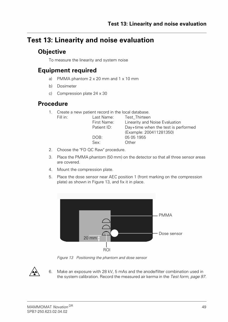
5. Place the dose sensor near AEC position 1 (front marking on the compression plate) as shown in Figure 13, and fix it in place.
Figure 13 Positioning the phantom and dose sensor
6. Make an exposure with 28 kV, 5 mAs and the anode/filter combination used in the system calibration. Record the measured air kerma in the Test form, page 97.
Dose sensor
ROI
PMMA
20 mm

Test 13: Linearity and noise evaluation
50 Quality control manualSPB7-250.623.02.04.02
7. Choose Tools > Rectangle and select a ROI (region of interest) of approx. 10 x 10 mm that is at a distance of 20 mm from the chest wall side and centered on the left and right. Record the displayed mean pixel value in the Test form, page 97.
8. Calculate d2, K2 and K•d and record the values in the Test form, page 97.
9. Repeat steps 6 to 8 with the mAs values specified in table Test form, page 97.
10. Calculate the mean values of d, K, d2, K2 and K•d and record them in the Test form, page 97.
11. Calculate the offset of the pixel value according to the following formula:
and record the result in the Test form, page 97.
12. Calculate the square of the correlation coefficient according to the following for-mula:
and record the result in the Test form, page 97.
13. Make an exposure with 28 kV, Mo/Mo and AEC H. Record the mAs value dis-played on the console and the measured air kerma in the Test form, page 97.
14. Select a ROI (region of interest) of approx. 10 x 10 mm for postprocessing with Tools > Rectangle and position it within the AEC region used (the AEC region can be displayed by selecting Tools > AEC Region) and record the displayed mean pixel value and the displayed standard deviation in the Test form, page 97.
15. Repeat steps 13 and 14 with W/Rh.
16. Calculate the SNR values according to the following formula:
and record them in the Test form, page 97.
17. Close the patient by clicking the Close patient button.
doffsetK2( )mean dmean• Kmean K d•( )mean•–
K2( )mean Kmean( )2–
------------------------------------------------------------------------------------------------------------------------------=
R2 K d•( )mean Kmean dmean•–( )2
K2( )mean Kmean( )2–( ) d2( )mean dmean( )2
–( )•----------------------------------------------------------------------------------------------------------------------------------------------------=
SNRd doffset–
s dard deviationtan-----------------------------------------------------------------=

Test 13: Linearity and noise evaluation
MAMMOMAT Novation DR 51SPB7-250.623.02.04.02
Performance criteria and corrective actionThe linear correlation coefficient R2 must be at least 0.99.The SNR value must be at least 40.
If any of the specified performance criteria is not fulfilled, the cause of the prob-lem must be identified and the problem must be corrected by a Siemens cus-tomer service engineer. The criterion must then be successfully retested by the MP before further examinations are performed with the system.
Test 14: Detector uniformity
52 Quality control manualSPB7-250.623.02.04.02
Test 14: Detector uniformity
ObjectiveTo measure the uniformity of the detector response across its entire surface.
Equipment requireda) PMMA phantom that mounts to the collimator (40 mm)
b) Compression plate simulator
Procedure1. Create a new patient record in the local database.
Fill in: Last Name: Test_FourteenFirst Name: Detector UniformityPatient ID: Day+time when the test is performed
(Example: 200411281350)DOB: 05 05 1955Sex: Other
2. Choose the "FD QC Raw" procedure.
3. Attach the PMMA phantom (40 mm) to the collimator.
4. Mount the compression plate simulator.
5. Make an exposure with 28 kV, AEC "H" mode and the anode/filter combination that was used in the system calibration.
6. Select a ROI (region of interest) of approx. 10 x 10 mm for postprocessing with Tools > Rectangle.
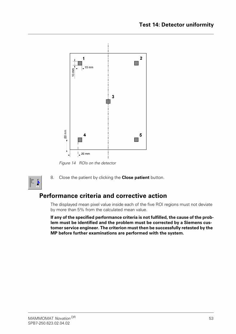
7. Measure the pixel value within each of the five regions located approx. 20 mm from the edges. Also refer to Figure 14. To do this, move the ROI to the relevant position and record the displayed mean value in the Test form, page 101.
Test 14: Detector uniformity
MAMMOMAT Novation DR 53SPB7-250.623.02.04.02
Figure 14 ROIs on the detector
8. Close the patient by clicking the Close patient button.
Performance criteria and corrective actionThe displayed mean pixel value inside each of the five ROI regions must not deviate by more than 5% from the calculated mean value.
If any of the specified performance criteria is not fulfilled, the cause of the prob-lem must be identified and the problem must be corrected by a Siemens cus-tomer service engineer. The criterion must then be successfully retested by the MP before further examinations are performed with the system.

Test 15: Phantom image quality
54 Quality control manualSPB7-250.623.02.04.02
Test 15: Phantom image quality
ObjectiveTo ensure adequate image quality.
Equipment requireda) RMI-156 phantom
b) Compression plate 24 x 30
Procedure1. Create a new patient record in the local database.
Fill in: Last Name: Test_FifteenFirst Name: Phantom Image QualityPatient ID: Day+time when the test is performed
(Example: 200411281350)DOB: 05 05 1955Sex: Other
2. Choose the "FD QC Raw" procedure.
3. Position the RMI-156 phantom centrally on the FD object table so that the wax insert points to the X-ray tube, see Figure 15. The phantom must be flush with the front edge of the object table, without a visible gap.
Figure 15 Positioning the PMMA phantom
4. Mount the compression plate and compress.
5. Select the clinically used setting by selecting the Opdose program corresponding to the phantom thickness on the control console. AEC sensor 2 must be selected at the AWS.

Test 15: Phantom image quality
MAMMOMAT Novation DR 55SPB7-250.623.02.04.02
6. Make an exposure and record the mAs and kV values displayed on the control panel as well as the set anode/filter combination in the Test form, page 103.
7. Examine the image and determine how many fibers, specks and masses can be identified. In doing so, change the gray value and magnification to achieve optimal results. Always count the number of visible objects from the largest object of a given type downward. Record the results in the Test form, page 103.
8. If a problem occurs when you are viewing the image at the AWS, send the image to the reporting station or the printer and then check it.
9. Close the patient by clicking the Close patient button.
Figure 16 Potentially visible objects in the ACR phantom
XXX XXX
Fibers
Specks (Microcalcifications)
Masses

Test 15: Phantom image quality
56 Quality control manualSPB7-250.623.02.04.02
Analysis• Count each fiber as one point if the full length of the fiber is visible. Count a
fiber as 0.5 points if not the entire but at least half the fiber is visible. • When examining the specks, the zoom and invert function may be useful.
Each speck group shall be counted as one point. A full speck group is counted as such if four or more specks are visible in the group in the proper locations. Count a speck group as 0.5 points if two or three specks of the group are vis-ible.
• Count each mass as one point if a density difference is visible in the correct location and the full mass is visible against the background. Count each mass as 0.5 points if a density difference is visible in the correct location but the full mass is not visible, so that the mass does not have a circular appearance.
Performance criteria and corrective actionThe table below shows how many fibers, specks and masses shall be identifiable (in total there are: 6 fibers, 5 specks and 5 masses.
Table 2 Object score criteria
If any of the specified performance criteria is not fulfilled, the cause of the prob-lem must be identified and the problem must be corrected by a Siemens cus-tomer service engineer. The criterion must then be successfully retested by the MP before further examinations are performed with the system.
Phantom used Required
Fibers ≥ 5
RMI-156 phantom Specks (Microcalcifica-tions)
≥ 4
Masses ≥ 4

Test 16: Phantom image quality – Maximum resolution
MAMMOMAT Novation DR 57SPB7-250.623.02.04.02
Test 16: Phantom image quality – Maximum resolution
ObjectiveTo ensure that the maximum resolution is at least 7/mm.
Equipment requireda) Mammography line pair phantom (2 to 10 lp/mm)
b) PMMA phantom 2 x 20 mm and 1 x 10 mm
c) Compression plate 24 x 30
Procedure1. Create a new patient record in the local database.
Fill in: Last Name: Test_SixteenFirst Name: Maximum ResolutionPatient ID: Day+time when the test is performed
(Example: 200411281350)DOB: 05 05 1955Sex: Other
2. Choose the "FD QC Raw" procedure.
3. Mount the compression plate.
4. Select the Opdose program for 50 mm on the control panel (default: program 3, see Test 1: Clinical settings). AEC sensor 3 must be selected at the AWS.
5. Position the PMMA phantom (50 mm) centrally and flush with the front detector edge. Place the line pair phantom diagonally on the plexiglas phantom (see Figure 17). Using the markings on the compression plate, check that AEC sensor area 3 (rear marking) is not covered.
Figure 17 Placing the resolution phantom
45
PMMA

Test 16: Phantom image quality – Maximum resolution
58 Quality control manualSPB7-250.623.02.04.02
6. Make an exposure and record the mAs and kV values displayed on the control panel as well as the set anode/filter combination in the Test form, page 105.
7. Examine the image and determine the highest resolution of the line pairs at which the bars and gaps can be clearly differentiated. In doing so, change the gray value and magnification to achieve optimal results. Record the result in the Test form, page 105.
8. If a problem occurs when you are viewing the image at the AWS, send the image to the reporting station or the printer and then check it.
9. Close the patient by clicking the Close patient button.
Performance criteria and corrective actionThe measured resolution must be at least 7 lp/mm.
If any of the specified performance criteria is not fulfilled, the cause of the prob-lem must be identified and the problem must be corrected by a Siemens cus-tomer service engineer. The criterion must then be successfully retested by the MP before further examinations are performed with the system.

Test 17: Mean glandular dose
MAMMOMAT Novation DR 59SPB7-250.623.02.04.02
Test 17: Mean glandular dose
ObjectiveTo measure the mean glandular dose to ensure that it does not exceed the admissible maximum value specified in the regulations for film-screen systems and FFDM sys-tems (FFDM: Full-Field Digital Mammography).
Equipment requireda) Dosimeter, calibrated at the mammography X-ray beam energies
b) PMMA phantom 2 x 20 mm and 1 x 10 mm
c) Compression plate 24 x 30
RequirementsThe HVL values determined for the system are required for this test. These values can be found in the system documentation that was handed over to the customer at the time of installation.
Procedure1. Create a new patient record in the local database.
Fill in: Last Name: Test_SeventeenFirst Name: Mean Glandular DosePatient ID: Day+time when the test is performed
(Example: 200411281350)DOB: 05 05 1955Sex: Other
2. Choose the "FD QC Raw" procedure.
3. Mount the compression plate.
4. Position the PMMA phantom (50 mm) on the detector so that all three sensor ar-eas are covered, and place the dosimeter near AEC position 1 (chest wall side marking on the compression plate) at the same level as the top side of the PMMA phantom, see Figure 18. If necessary, raise the position of the dosimeter by plac-ing suitable objects such as additional PMMA phantoms underneath.

Test 17: Mean glandular dose
60 Quality control manualSPB7-250.623.02.04.02
Figure 18 Positioning the PMMA phantom and the dosimeter
5. Make an exposure with 28 kV, Mo/Mo and AEC D and record the mAs displayed on the control panel as well as the measured air kerma (in mGy) in the Test form, page 107.
6. Repeat step 5 with Mo/Rh and W/Rh.
7. Close the patient by clicking the Close patient button.
8. Calculate the mean glandular dose with the aid of the tables in the Test form, page 107.
Performance criteria and corrective actionThe calculated glandular dose must not exceed 2.5 mGy.
If any of the specified performance criteria is not fulfilled, the cause of the prob-lem must be identified and the problem must be corrected by a Siemens cus-tomer service engineer. The criterion must then be successfully retested by the MP before further examinations are performed with the system.
Dose sensor
PMMA

Test 18: Ghost image evaluation
MAMMOMAT Novation DR 61SPB7-250.623.02.04.02
Test 18: Ghost image evaluation
ObjectiveTo measure ghosting
Equipment requireda) PMMA phantom that mounts to the collimator (40 mm thick)
b) 2 mm steel plate (object table size)
c) 2 mm steel plate (approx. 3 x 10 cm)
d) Compression plate simulator
e) Timer (stop watch)
f) Paper clips
Requirements• Prior to the test, a new gain calibration must be performed (see MAMMO-
MAT Novation DR Operator Manual); after that, wait at least 10 minutes. No exposures must be made during this time.
Procedure1. Create a new patient record in the local database.
Fill in: Last Name: Test_EighteenFirst Name: GhostingPatient ID: Day+time when the test is performed
(Example: 200411281350)DOB: 05 05 1955Sex: Other
2. Choose the "FD QC Raw" procedure.
3. Cover the object table with the 2 mm steel plate.
4. Mount the compression plate simulator.
5. Make an exposure with 23 kV, 2 mAs and Mo/Mo.
6. Remove the large 2 mm steel plate and position the 2 mm steel plate (3 x 10 cm) centrally against the front edge, see Figure 19. Mark the corners with paper clips.
NOTE!NOTE!The paper clips must remain in the same position during the following two exposures.

Test 18: Ghost image evaluation
62 Quality control manualSPB7-250.623.02.04.02
Figure 19 Second exposure
7. Make an exposure with 28 kV, 200 mAs and Mo/Mo.
8. Start the timer right after releasing the exposure.
9. Remove the 2 mm steel plate and mount the PMMA phantom (40 mm) to the collimator. Make sure the paper clips do not move.
10. After 180 seconds, make an exposure with 28 kV, 14 mAs and Mo/Mo.
11. Determine the offset. To do this, go to the first exposure (with 2 mAs) and select a ROI (region of interest) of approx. 10 x 10 mm for postprocessing with Tools > Rectangle. Position the ROI centrally approx. 20 mm from the front detector edge and record the displayed mean pixel value as offset in the Test form, page 111.
Steel plate
Paper clip

Test 18: Ghost image evaluation
MAMMOMAT Novation DR 63SPB7-250.623.02.04.02
Figure 20 Third exposure after 180 seconds
12. Go to the third exposure (with 14 mAs) and select a ROI (region of interest) of approx. 10 x 10 mm for postprocessing with Tools > Rectangle. For each of the four positions shown in Figure 20, determine the pixel value within (PV1) and out-side (PV2) the previously covered area. To do this, move the ROI to the relevant position and record the displayed mean pixel value in the Test form, page 111.
13. Close the patient by clicking the Close patient button.
14. Calculate the ghosting factor for each position according to the following formu-lar:
and record the calculated values in the Test form, page 111.
15. Calculate the mean value from the four ghosting factors and record it in the Test form, page 111.
Performance criteria and corrective actionThe mean ghosting factor must be less than 3 %.
If any of the specified performance criteria is not fulfilled, the cause of the prob-lem must be identified and the problem must be corrected by a Siemens cus-tomer service engineer. The criterion must then be successfully retested by the MP before further examinations are performed with the system.
Position 3Position 2
Position 4Position 1
Ghosting factorPV1 PV2–( )
PV1 PV2 2 Offset⋅( )–+( )-------------------------------------------------------------------------------------- 200%⋅=

Test 19: AWS monitor check
64 Quality control manualSPB7-250.623.02.04.02
Test 19: AWS monitor check
ObjectiveTo assess the quality of the acquisition workstation monitor.
Equipment requireda) SMPTE test pattern (included in syngo)
Procedure1. Clean the monitor.
a) The monitor surface should be cleaned with a soft tissue material, e.g. a cot-ton cloth or lens cleaning cloth.
b) To remove stubborn stains, moisten the cloth with water to enhance its clean-ing power.
3. Select the Viewing task card.
4. Open the Patient Browser and select Service images, technical images.
5. Open the SMPTE image in the Viewing task card. Make sure the SMPTE image covers the entire viewing area, i.e. the window must not be divided into four viewing areas.Check that the window center is set to 2048 and the window width to 4096. Se-lect Image > Acquisition Size to check that the image is displayed in acquisition size.
6. The gray scale is shown as a series of squares in the center of the SMPTE image, ranging from black (0%) to white (100%). The 0% and 100% squares each con-tain smaller squares within them that represent signal level steps of 5% and 95% respectively (see Figure 21). It should be possible to differentiate the inner square from the larger square that contains it. The 5% square is normally quite difficult to differentiate. If this is not possible, perform the test again with dimmed room light.
Figure 21 Arrangement of squares

Test 19: AWS monitor check
MAMMOMAT Novation DR 65SPB7-250.623.02.04.02
If the 5% and 95% squares are not visible, the monitor brightness and contrast must be readjusted. To do this, press the menu button on the monitor and follow the in-structions on the screen.In general, monitor contrast should be set to 100(%). To obtain acceptable brightness values, first set a low brightness value and then slowly increase the brightness until the 5% square is visible in the 0% square of the SMPTE image. In general, a higher brightness is recommended. However, the setting should not be too high, causing black areas on the screen to become light gray. After changing the monitor settings, repeat the entire test to check the monitor image quality with these settings.
7. Visually check the monitor for streaking, flicker and shadows.
8. The spatial resolution (linearity) and aliasing (distortion) of the monitor are consid-ered to be within acceptable limits if the resolution bar pattern in the test image can be seen as patterns of white and black pairs. Inspect the 6 squares with al-ternating black and white, vertical and horizontal bars of different widths in each corner (see Figure 22) and in the center of the screen. You should be able to dif-ferentiate all the bars, from wide to narrow (6 pixels, 4 pixels and 2 pixels), both horizontally and vertically.
Figure 22 Arrangement of resolution bar pattern
9. Close the patient by clicking the Close patient button.

Test 19: AWS monitor check
66 Quality control manualSPB7-250.623.02.04.02
Performance criteria and corrective action• The 5% and 95% squares must be visible.
• The resolution bar patterns in the four corners and in the center of the image (see Figure 22) must be visible.
If any of the specified performance criteria is not fulfilled, the cause of the prob-lem must be identified and the problem must be corrected by a Siemens cus-tomer service engineer. The criterion must then be successfully retested by the MP before further examinations are performed with the system.

Test 20: Printer check
MAMMOMAT Novation DR 67SPB7-250.623.02.04.02
Test 20: Printer checkThis test is required only if a laser camera is used.
ObjectiveTo assess the quality of the laser camera.
Equipment requireda) Calibrated densitometer
Procedure1. Log in as described under Startup and login.
2. Select the service patient in the Patient Browser.
3. Select the SMPTE image of the service patient and open it in the Viewing task card.
4. Send the image to a printer.
5. The printer must be configured for Min. Density = 20 and Max. Density = 350.Information on the Min. Density, Max. Density and LUT used can be found in the service menu.
6. Evaluate the printed SMPTE image by measuring the eleven density values from 0 to 100 % with the densitometer, and record the measured values in the Test form, page 115.
Performance criteria and corrective actionThe values for the different optical densities must be within the action limits specified in the Test form, page 115.
If any of the specified performance criteria is not fulfilled, the cause of the prob-lem must be identified and the problem must be corrected by a Siemens cus-tomer service engineer. The criterion must then be successfully retested by the MP before further examinations are performed with the system.
For the qualification of the printer please follow the printer manufacturer's rec-ommendations.

Test 20: Printer check
68 Quality control manualSPB7-250.623.02.04.02
For notes

Appendix 1 to MAMMOMAT Novation DR Quality Control Manual
MAMMOMAT Novation DR 69SPB7-250.623.02.04.02
Appendix 1 – Test formsMAMMOMAT Novation DR

Appendix 1 to MAMMOMAT Novation DR Quality Control Manual
70 Quality Control ManualSPB7-250.623.02.04.02
For notes
Appendix 1 to MAMMOMAT Novation DR Quality Control Manual
MAMMOMAT Novation DR 71SPB7-250.623.02.04.02
Test form Test 1: Clinical settings
NOTE!NOTE!Copy this Appendix, record the measured values on the copy and file it together with this QC manual.
Site: ________________________________________________
________________________________________________
Room: ________________________________________________
Type of test: ________________________________________________
Performed by: ________________________________________________
Date: ________________________________________________

Appendix 1 to MAMMOMAT Novation DR Quality Control Manual
72 Quality Control ManualSPB7-250.623.02.04.02
Opdose setting used (enter only if setting deviates from the factory settings indicated in brackets):
Opdose AEC H AEC D Manual
Main exposure technique used
l l l l
Mo/Mo Mo/Rh W/Rh
Main anode/filter combination used l l l
Program Compression height range
Anode/filter combination
kV value AEC
1(0 ... 29 mm) (W/Rh) (27) (H)
2(30 ... 45 mm) (W/Rh) (27) (H)
3(45 ... 59 mm) (W/Rh) (28) (H)
4(≥ 60 mm) (W/Rh) (32) (H)
Comments: ____________________________________________________________________________
___________________________________________________________________________________________
___________________________________________________________________________________________

Appendix 1 to MAMMOMAT Novation DR Quality Control Manual
MAMMOMAT Novation DR 73SPB7-250.623.02.04.02
Test form Test 2: Mechanical inspection and follow-up
NOTE!NOTE!Copy this Appendix, record the measured values on the copy and file it together with this QC manual.
Site: ________________________________________________
________________________________________________
Room: ________________________________________________
Type of test: ________________________________________________
Performed by: ________________________________________________
Date: ________________________________________________

Appendix 1 to MAMMOMAT Novation DR Quality Control Manual
74 Quality Control ManualSPB7-250.623.02.04.02
Mechanical inspection and follow-up
Test no.: Performance criteria
Passed Failed
1. Inspection of cables --- l l2. Control panel lights up --- l l3. LED indicates tube close to floor --- l l4. Test of motorized movements --- l l5. Movements disabled --- l l6. Emergency Stop button --- l l7. Manual compression buttons --- l l8. Decompression button --- l l9. No sharp edges --- l l10. Radiation shield --- l l11. Focal spot position --- l l12. Vertical movements --- l l13. Foot switches --- l l14. Attachments --- l l
Comments: ____________________________________________________________________________
___________________________________________________________________________________________
___________________________________________________________________________________________

Appendix 1 to MAMMOMAT Novation DR Quality Control Manual
MAMMOMAT Novation DR 75SPB7-250.623.02.04.02
Test form Test 3: Compression
NOTE!NOTE!Copy Appendix 1, record the measured values on the copy and file it together with this QC manual.
Site: ___________________________________________________________
___________________________________________________________
Room: ___________________________________________________________
Type of test: ___________________________________________________________
Performed by: ___________________________________________________________
Date: ___________________________________________________________
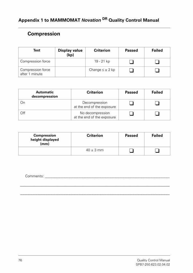
Appendix 1 to MAMMOMAT Novation DR Quality Control Manual
76 Quality Control ManualSPB7-250.623.02.04.02
Compression
Test Display value (kp)
Criterion Passed Failed
Compression force 19 - 21 kp l lCompression force after 1 minute
Change ≤ ± 2 kp l l
Automatic decompression
Criterion Passed Failed
On Decompression at the end of the exposure
l l
Off No decompression at the end of the exposure
l l
Compression height displayed
(mm)
Criterion Passed Failed
40 ± 3 mm l l
Comments: ____________________________________________________________________________
___________________________________________________________________________________________
___________________________________________________________________________________________

Appendix 1 to MAMMOMAT Novation DR Quality Control Manual
MAMMOMAT Novation DR 77SPB7-250.623.02.04.02
Test form Test 4: Chest wall missed tissue
NOTE!NOTE!Copy this Appendix, record the measured values on the copy and file it together with this QC manual.
Chest wall missed tissue
Site: ___________________________________________________________
___________________________________________________________
Room: ___________________________________________________________
Type of test: ___________________________________________________________
Performed by: ___________________________________________________________
Date: ___________________________________________________________
Performance criteria Passed Failed
Coin diameter (d1):
Rear coin edgeto front detector edge dis-tance (d2)
Calculated chest wall missed tissue, α = d1 - d2: ≤ 5 mm l l
Comments: ____________________________________________________________________________
___________________________________________________________________________________________
___________________________________________________________________________________________

Appendix 1 to MAMMOMAT Novation DR Quality Control Manual
78 Quality Control ManualSPB7-250.623.02.04.02
For notes

Appendix 1 to MAMMOMAT Novation DR Quality Control Manual
MAMMOMAT Novation DR 79SPB7-250.623.02.04.02
Test form Test 5: Compression plate alignment
NOTE!NOTE!Copy this Appendix, record the measured values on the copy and file it together with this QC manual.
Compression plate overlapPerformance criteria: Measured value + α ≤ 6.5 mm
Chest wall edge of compression plate not visible in the image
Site: ___________________________________________________________
___________________________________________________________
Room: ___________________________________________________________
Type of test: ___________________________________________________________
Performed by: ___________________________________________________________
Date: ___________________________________________________________
Compression plates Measured value+ α
Passed Failed
Low edge, 18 x 24 cmPart number: 10048516
l l
High edge, 18 x 24 cmPart number: 10048519
l l
Low edge, 24 x 30 cmPart number: 10048518
l l
High edge, 24 x 30 cmPart number: 10048515
l l
High edge, 24x30 cm, Flex Part number: 10048517
l l
High edge, 20 x 22 cmPart number: 10048520
l l
High edge, 20 x 22 cm, Flex Part number: 10048521
l l
High edge, 20 x 24 cm Part number: 10390201
l l

Appendix 1 to MAMMOMAT Novation DR Quality Control Manual
80 Quality Control ManualSPB7-250.623.02.04.02
High edge, 20 x 24 cm, FlexPart number: 10390202
l lDetail compression plate 9 x 9Part number: 10048513
l l
Perforated biopsy compression platePart number: 10046676
l l
Alphanumeric plate Part number: 10140380
l l
SpotPlus plate Part number: 10253164
l l
Axilla plate Part number: 10040381
l l
Compression plate 1.5Part number: 10048522
l l
Spot compression plate 1.5Part number: 10048524
l l
Compression plate 1.8Part number: 10048523
l l
Spot compression plate 1.8Part number: 10048525
l l
l l
l l
Comments: ____________________________________________________________________________
___________________________________________________________________________________________
___________________________________________________________________________________________

Appendix 1 to MAMMOMAT Novation DR Quality Control Manual
MAMMOMAT Novation DR 81SPB7-250.623.02.04.02
Test form Test 6: Collimator assessmentNOTE!NOTE!
Copy Appendix 1, record the measured values on the copy and file it together with this QC manual.
Collimator assessmentB is the deviation between radiation field and active detector area.
A is the deviation between radiation field and light field.
If B is positive, the X-ray field is larger than the detector area.
If B is negative, the X-ray field is smaller than the detector area.
If A is positive, the X-ray field is smaller than the light field.
If A is negative, the X-ray field is larger than the light field.
Site: ___________________________________________________
___________________________________________________
Room: ___________________________________________________
Type of test: ___________________________________________________
Performed by: ___________________________________________________
Date: ___________________________________________________

Appendix 1 to MAMMOMAT Novation DR Quality Control Manual
82 Quality Control ManualSPB7-250.623.02.04.02
Distances measured with large focal spot
Distances measured with small focal spot (optional)
Position F/A combi-nation
Value light field VLF (mm)
Value X-ray field VSF (mm)
Value detector field VDF (mm)
A = VSF - VLF (mm)
B = VDF - VLF (mm)
Chest wall edge (pos. 1)
Mo/Mo
Right edge (pos. 2)
Nipple-side edge (pos. 3)
Left edge (pos. 4)
Chest wall edge (pos. 1)
W/Rh
Right edge (pos. 2)
Nipple-side edge (pos. 3)
Left edge (pos. 4)

Appendix 1 to MAMMOMAT Novation DR Quality Control Manual
MAMMOMAT Novation DR 83SPB7-250.623.02.04.02
Acceptance criteria:
Sum of absolute valuesright and left
Performance criteria
Large focal spot Small focal spot Passed Failed
Mo/Mo W/Rh Mo/Mo W/Rh
| Apos2 | + | Apos4 | (mm) ≤ 13 mm l l
Sum of absolute valuesnipple and chest
Performance criteria
Large focal spot Small focal spot Passed Failed
Mo/Mo W/Rh Mo/Mo W/Rh
| Apos1 | + | Apos3 | (mm) ≤ 13 mm l l
Sum of absolute valuesright and left
Performance criteria
Large focal spot Small focal spot Passed Failed
Mo/Mo W/Rh Mo/Mo W/Rh
| Bpos2 | + | Bpos4 | (mm) ≤ 13 mm l l
Sum of absolute valuesnipple and chest
Performance criteria
Large focal spot Small focal spot Passed Failed
Mo/Mo W/Rh Mo/Mo W/Rh
| Bpos1 | + | Bpos3 | (mm) ≤ 13 mm l l
Value on the nipple side Performance criteria
Large focal spot Small focal spot Passed Failed
Mo/Mo W/Rh Mo/Mo W/Rh
Bpos1 (mm) ≤ 5 mm l l

Appendix 1 to MAMMOMAT Novation DR Quality Control Manual
84 Quality Control ManualSPB7-250.623.02.04.02
Light intensity measurement test
Value (lux)
Acceptance criteria Passed Failed
Area 1
Area 2
Area 3
Area 4
Mean value > 160 lux l l
Comments: ____________________________________________________________________________
___________________________________________________________________________________________
___________________________________________________________________________________________

Appendix 1 to MAMMOMAT Novation DR Quality Control Manual
MAMMOMAT Novation DR 85SPB7-250.623.02.04.02
Test form Test 7: Tube voltage measurement and re-producibility
NOTE!NOTE!Copy this Appendix, record the measured values on the copy and file it together with this QC manual.
Site: ___________________________________________________________
___________________________________________________________
Room: ___________________________________________________________
Type of test: ___________________________________________________________
Performed by: ___________________________________________________________
Date: ___________________________________________________________
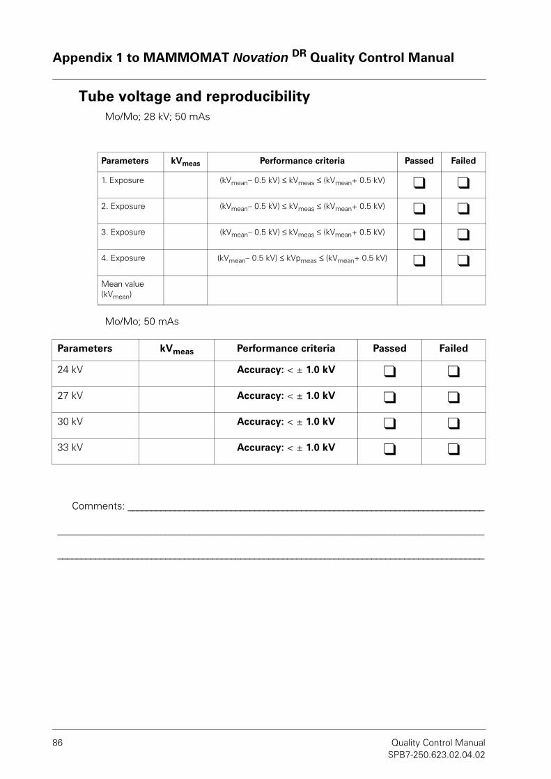
Appendix 1 to MAMMOMAT Novation DR Quality Control Manual
86 Quality Control ManualSPB7-250.623.02.04.02
Tube voltage and reproducibilityMo/Mo; 28 kV; 50 mAs
Mo/Mo; 50 mAs
Parameters kVmeas Performance criteria Passed Failed
1. Exposure (kVmean– 0.5 kV) ≤ kVmeas ≤ (kVmean+ 0.5 kV) l l2. Exposure (kVmean– 0.5 kV) ≤ kVmeas ≤ (kVmean+ 0.5 kV) l l3. Exposure (kVmean– 0.5 kV) ≤ kVmeas ≤ (kVmean+ 0.5 kV) l l4. Exposure (kVmean– 0.5 kV) ≤ kVpmeas ≤ (kVmean+ 0.5 kV) l lMean value (kVmean)
Parameters kVmeas Performance criteria Passed Failed
24 kV Accuracy: < ± 1.0 kV l l27 kV Accuracy: < ± 1.0 kV l l30 kV Accuracy: < ± 1.0 kV l l33 kV Accuracy: < ± 1.0 kV l l
Comments: ____________________________________________________________________________
___________________________________________________________________________________________
___________________________________________________________________________________________
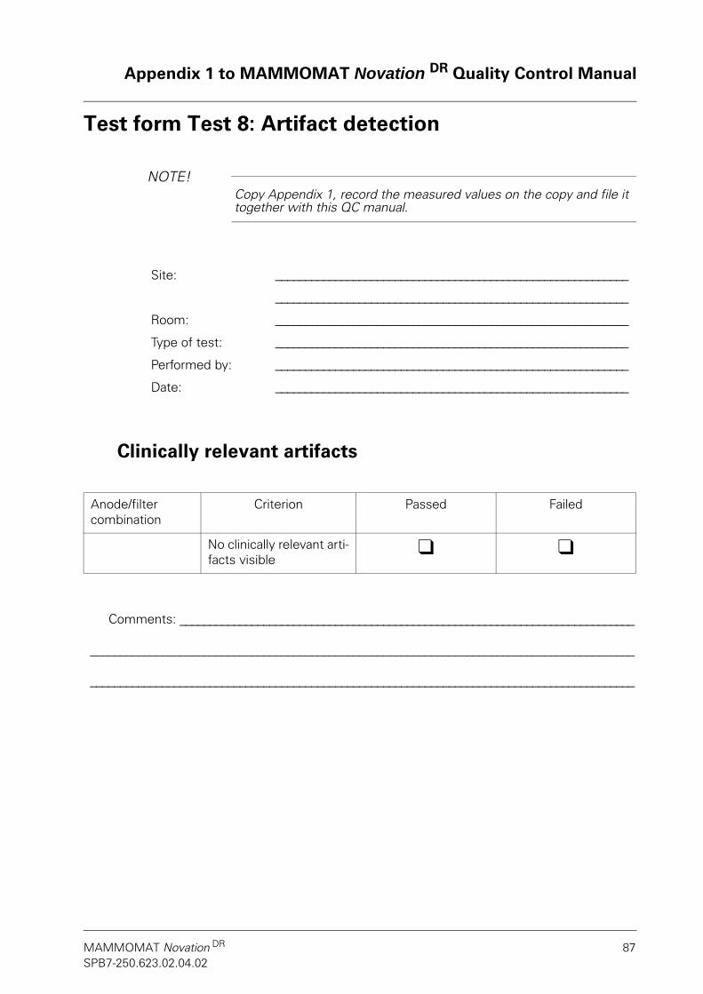
Appendix 1 to MAMMOMAT Novation DR Quality Control Manual
MAMMOMAT Novation DR 87SPB7-250.623.02.04.02
Test form Test 8: Artifact detection
NOTE!NOTE!Copy Appendix 1, record the measured values on the copy and file it together with this QC manual.
Clinically relevant artifacts
Site: ___________________________________________________________
___________________________________________________________
Room: ___________________________________________________________
Type of test: ___________________________________________________________
Performed by: ___________________________________________________________
Date: ___________________________________________________________
Anode/filter combination
Criterion Passed Failed
No clinically relevant arti-facts visible
l l
Comments: ____________________________________________________________________________
___________________________________________________________________________________________
___________________________________________________________________________________________

Appendix 1 to MAMMOMAT Novation DR Quality Control Manual
88 Quality Control ManualSPB7-250.623.02.04.02
For notes

Appendix 1 to MAMMOMAT Novation DR Quality Control Manual
MAMMOMAT Novation DR 89SPB7-250.623.02.04.02
Test form Test 9: AEC: Safety test
NOTE!NOTE!Copy Appendix 1, record the measured values on the copy and file it together with this QC manual.
AEC: Safety test
Site: ___________________________________________________________
___________________________________________________________
Room: ___________________________________________________________
Type of test: ___________________________________________________________
Performed by: ___________________________________________________________
Date: ___________________________________________________________
Test Passed Failed
AEC: Safety cut-off l lError 504, 578 or 579 l l
Comments: ____________________________________________________________________________
___________________________________________________________________________________________
___________________________________________________________________________________________

Appendix 1 to MAMMOMAT Novation DR Quality Control Manual
90 Quality Control ManualSPB7-250.623.02.04.02
For notes

Appendix 1 to MAMMOMAT Novation DR Quality Control Manual
MAMMOMAT Novation DR 91SPB7-250.623.02.04.02
Test form Test 10: AEC: Reproducibility of automatic exposure control
NOTE!NOTE!Copy this Appendix, record the measured values on the copy and file it together with this QC manual.
Site: ___________________________________________________________
___________________________________________________________
Room: ___________________________________________________________
Type of test: ___________________________________________________________
Performed by: ___________________________________________________________
Date: ___________________________________________________________

Appendix 1 to MAMMOMAT Novation DR Quality Control Manual
92 Quality Control ManualSPB7-250.623.02.04.02
AEC: Reproducibility of automatic exposure control
Anode/Filter: ________________________ kV: _________ H/D: _________
Exposureno.
mAs Mean pixel value
1
2
3
4
5
Value Performance criteria
Passed Failed
Mean value(mAs)
Max. deviation from mean value (mAs)
≤ 5% l l
Mean value (mean pixel value)
Max. deviation from mean value (mean pixel value)
≤ 5% l l
Comments: ____________________________________________________________________________
___________________________________________________________________________________________
___________________________________________________________________________________________

Appendix 1 to MAMMOMAT Novation DR Quality Control Manual
MAMMOMAT Novation DR 93SPB7-250.623.02.04.02
Test form Test 11: AEC: Long-term reproducibility of automatic exposure control
NOTE!NOTE!Copy this Appendix, record the measured values on the copy and file it together with this QC manual.
AEC: Long-term reproducibility of automatic exposure control
Site: ___________________________________________________________
___________________________________________________________
Room: ___________________________________________________________
Type of test: ___________________________________________________________
Performed by: ___________________________________________________________
Date: ___________________________________________________________
Date mAs kV Anode/Filter
AEC H/D
Mean pixel value
Deviation mean pixel value (%)
Performance criterionDeviation
max. ± 10%
Baseline Passed Failed
1 l l2 l l3 l l4 l l5 l l
Comments: ____________________________________________________________________________
___________________________________________________________________________________________
___________________________________________________________________________________________

Appendix 1 to MAMMOMAT Novation DR Quality Control Manual
94 Quality Control ManualSPB7-250.623.02.04.02
For notes

Appendix 1 to MAMMOMAT Novation DR Quality Control Manual
MAMMOMAT Novation DR 95SPB7-250.623.02.04.02
Test form Test 12: AEC: Tracking test
NOTE!NOTE!Copy Appendix 1, record the measured values on the copy and file it together with this QC manual.
Object thickness and tube voltage compensation
Site: ___________________________________________________________
___________________________________________________________
Room: ___________________________________________________________
Type of test: ___________________________________________________________
Performed by: ___________________________________________________________
Date: ___________________________________________________________
Thickness of PMMA (mm)
mAs kV Anode/Filter AEC H/D Mean pixel value
20
30
40
50
60
70
Mean value (mean pixel
value)
Maximum deviation
(%)
Criteria Passed Failed
≤ 15% l l
Comments: ____________________________________________________________________________
___________________________________________________________________________________________
___________________________________________________________________________________________

Appendix 1 to MAMMOMAT Novation DR Quality Control Manual
96 Quality Control ManualSPB7-250.623.02.04.02
For notes

Appendix 1 to MAMMOMAT Novation DR Quality Control Manual
MAMMOMAT Novation DR 97SPB7-250.623.02.04.02
Test form Test 13: Linearity and noise evaluation
NOTE!NOTE!Copy Appendix 1, record the measured values on the copy and file it together with this QC manual.
Site: ___________________________________________________________
___________________________________________________________
Room: ___________________________________________________________
Type of test: ___________________________________________________________
Performed by: ___________________________________________________________
Date: ___________________________________________________________
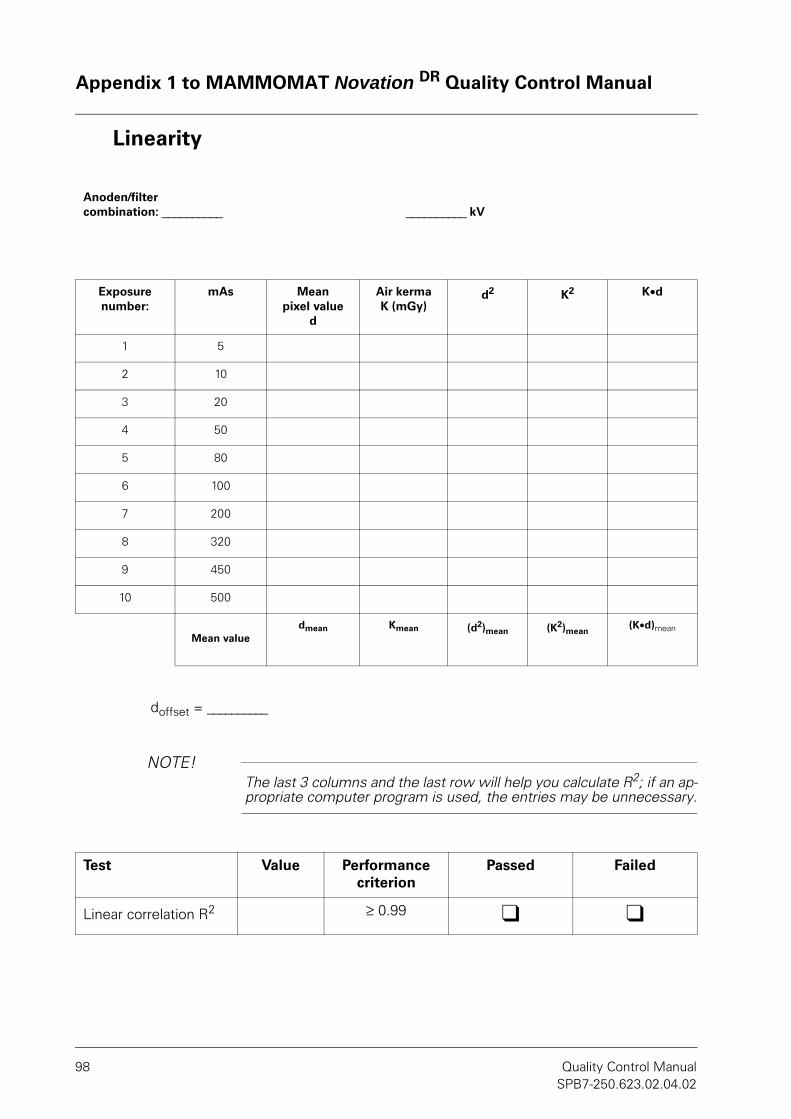
Appendix 1 to MAMMOMAT Novation DR Quality Control Manual
98 Quality Control ManualSPB7-250.623.02.04.02
Linearity
doffset = __________
NOTE!NOTE!The last 3 columns and the last row will help you calculate R2; if an ap-propriate computer program is used, the entries may be unnecessary.
Anoden/filter combination: __________ __________ kV
Exposure number:
mAs Mean pixel value
d
Air kerma K (mGy)
d2 K2 K•d
1 5
2 10
3 20
4 50
5 80
6 100
7 200
8 320
9 450
10 500
Mean valuedmean Kmean (d2)mean (K2)mean
(K•d)mean
Test Value Performance criterion
Passed Failed
Linear correlation R2 ≥ 0.99 l l

Appendix 1 to MAMMOMAT Novation DR Quality Control Manual
MAMMOMAT Novation DR 99SPB7-250.623.02.04.02
Noise evaluation
28 kV, AEC H
Anode/fil-ter combi-
nation
mAs Air kerma (mGy)
Mean pixel value
d
Standard deviation
SNR Perfor-mance crite-rion
Passed Failed
Mo/Mo ≥ 40 l lW/Rh ≥ 40 l l
Comments: ____________________________________________________________________________
___________________________________________________________________________________________
___________________________________________________________________________________________

Appendix 1 to MAMMOMAT Novation DR Quality Control Manual
100 Quality Control ManualSPB7-250.623.02.04.02
For notes

Appendix 1 to MAMMOMAT Novation DR Quality Control Manual
MAMMOMAT Novation DR 101SPB7-250.623.02.04.02
Test form Test 14: Detector uniformity
NOTE!NOTE!Copy this Appendix, record the measured values on the copy and file it together with this QC manual.
Site: ___________________________________________________________
___________________________________________________________
Room: ___________________________________________________________
Type of test: ___________________________________________________________
Performed by: ___________________________________________________________
Date: ___________________________________________________________

Appendix 1 to MAMMOMAT Novation DR Quality Control Manual
102 Quality Control ManualSPB7-250.623.02.04.02
Detector uniformity
Results from ROI statistics
Mo/Mo Mo/Rh W/Rh
Anode/filter combination used l l l
Mean pixel value
% deviation from mean
Performance criteria
Passed Failed
Required
Area 1 ≤ 5% l lArea 2 ≤ 5% l lArea 3 ≤ 5% l lArea 4 ≤ 5% l lArea 5 ≤ 5% l lMean value
Comments: ____________________________________________________________________________
___________________________________________________________________________________________
___________________________________________________________________________________________
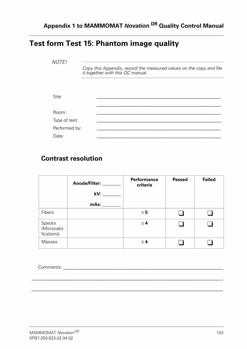
Appendix 1 to MAMMOMAT Novation DR Quality Control Manual
MAMMOMAT Novation DR 103SPB7-250.623.02.04.02
Test form Test 15: Phantom image quality
NOTE!NOTE!Copy this Appendix, record the measured values on the copy and file it together with this QC manual.
Contrast resolution
Site: ___________________________________________________________
___________________________________________________________
Room: ___________________________________________________________
Type of test: ___________________________________________________________
Performed by: ___________________________________________________________
Date: ___________________________________________________________
Anode/Filter: _________
kV: _________
mAs: _________
Performance criteria
Passed Failed
Fibers ≥ 5 l lSpecks (Microcalci-fications)
≥ 4 l l
Masses ≥ 4 l l
Comments: ____________________________________________________________________________
___________________________________________________________________________________________
___________________________________________________________________________________________

Appendix 1 to MAMMOMAT Novation DR Quality Control Manual
104 Quality Control ManualSPB7-250.623.02.04.02
For notes

Appendix 1 to MAMMOMAT Novation DR Quality Control Manual
MAMMOMAT Novation DR 105SPB7-250.623.02.04.02
Test form Test 16: Phantom image quality – Maximum resolution
NOTE!NOTE!Copy Appendix 1, record the measured values on the copy and file it together with this QC manual.
Resolution
Site: ___________________________________________________________
___________________________________________________________
Room: ___________________________________________________________
Type of test: ___________________________________________________________
Performed by: ___________________________________________________________
Date: ___________________________________________________________
Anode/Filter: ___________
kV: ___________
mAs: ___________
Performance criteria Passed Failed
Resolution measured
lp: _________
≥ 7 lp/mm l l
Comments: ____________________________________________________________________________
___________________________________________________________________________________________
___________________________________________________________________________________________

Appendix 1 to MAMMOMAT Novation DR Quality Control Manual
106 Quality Control ManualSPB7-250.623.02.04.02
For notes

Appendix 1 to MAMMOMAT Novation DR Quality Control Manual
MAMMOMAT Novation DR 107SPB7-250.623.02.04.02
Test form Test 17: Mean glandular dose
NOTE!NOTE!Copy this Appendix, record the measured values on the copy and file it together with this QC manual.
Site: ___________________________________________________________
___________________________________________________________
Room: ___________________________________________________________
Type of test: ___________________________________________________________
Performed by: ___________________________________________________________
Date: ___________________________________________________________

Appendix 1 to MAMMOMAT Novation DR Quality Control Manual
108 Quality Control ManualSPB7-250.623.02.04.02
Prerequisites for calculating the mean glandular dose
Formula used:
D = K•g•c•s*
D Mean glandular dose
K Incident air kerma (without backscatter) at the upper surface of the PMMA
g Coupling factor between incident air kerma and mean glandular dose for a glandu-larity of 50% and for the Mo/Mo anode/filter combination
c Correction factor for deviations from the standard 50% glandularity
s Correction factor for anode/filter combinations other than Mo/Mo
The c and g factors are listed in the following table for different HVL values. They can be interpolated correspondingly for other HVL values. The values listed were derived from the typical breast thickness corresponding to a PMMA thickness of 50 mm on which the simulation calculation* is based.
* [D.R. Dance, C.L. Skinner, K.C. Young, J.R. Beckett. C.J. Kotre: Additional factors for the estimation of mean glandular breast dose using the UK mammography dosimetry protocolPhysics in Medicine and Biology 45, 3225-3240, 2000]
HVL (mm Al)
0.30 0.35 0.40 0.45 0.50 0.55 0.60
g factor 0.135 0.154 0.172 0.192 0.214 0.236 0.261
c factor 1.164 1.160 1.151 1.150 1.144 1.139 1.134
Mo/Mo Mo/Rh W/Rh
s factor 1.000 1.017 1.042

Appendix 1 to MAMMOMAT Novation DR Quality Control Manual
MAMMOMAT Novation DR 109SPB7-250.623.02.04.02
Mean glandular doseValues (at 28 kV) for the calculation
Calculation of the mean glandular dose
Anode/Filter mAs Air kerma(mGy)
HVL value (mm Al)
Mo/Mo
Mo/Rh
W/Rh
Anode/Filter
D = Kgcs (mGy) Performance criteria
Passed Failed
Mo/Mo
≤ 3.0 mGy
l lMo/Rh l lW/Rh l l
Comments: ____________________________________________________________________________
___________________________________________________________________________________________
___________________________________________________________________________________________

Appendix 1 to MAMMOMAT Novation DR Quality Control Manual
110 Quality Control ManualSPB7-250.623.02.04.02
For notes

Appendix 1 to MAMMOMAT Novation DR Quality Control Manual
MAMMOMAT Novation DR 111SPB7-250.623.02.04.02
Test form Test 18: Ghost image evaluation
NOTE!NOTE!Copy this Appendix, record the measured values on the copy and file it together with this QC manual.
Site: ________________________________________________
________________________________________________
Room: ________________________________________________
Type of test: ________________________________________________
Performed by: ________________________________________________
Date: ________________________________________________

Appendix 1 to MAMMOMAT Novation DR Quality Control Manual
112 Quality Control ManualSPB7-250.623.02.04.02
Ghost image evaluation
Offset = _______
Position Mean pixel value Ghosting factor(%)
PV1 PV2
1
2
3
4
Mean value ghost image factor (%)Performance
criteriaPassed Failed
< 3 % l l
Comments: ____________________________________________________________________________
___________________________________________________________________________________________
___________________________________________________________________________________________

Appendix 1 to MAMMOMAT Novation DR Quality Control Manual
MAMMOMAT Novation DR 113SPB7-250.623.02.04.02
Test form Test 19: AWS monitor checkNOTE!NOTE!
Copy this Appendix, record the measured values on the copy and file it together with this QC manual.
AWS monitor check and viewing conditions
Site: ________________________________________________
________________________________________________
Room: ________________________________________________
Type of test: ________________________________________________
Performed by: ________________________________________________
Date: ________________________________________________
Grayscale contrast: Yes No
5% square is visible inside 0% square
l l
Performance criteria: Yes
95% square is visible inside 100% square
l l
Performance criteria: Yes
Comments: ____________________________________________________________________________
___________________________________________________________________________________________
___________________________________________________________________________________________

Appendix 1 to MAMMOMAT Novation DR Quality Control Manual
114 Quality Control ManualSPB7-250.623.02.04.02
Spatial resolution: Yes No
All lines in all bar patterns can be differentiated
l l
Performance criteria: Yes
Comments: ____________________________________________________________________________
___________________________________________________________________________________________
___________________________________________________________________________________________
Visual inspection:
Yes No
Streaking l lPerformance criteria: No
Flicker l lPerformance criteria: No
Shadows l lPerformance criteria: No
Comments: ____________________________________________________________________________
___________________________________________________________________________________________
___________________________________________________________________________________________

Appendix 1 to MAMMOMAT Novation DR Quality Control Manual
MAMMOMAT Novation DR 115SPB7-250.623.02.04.02
Test form Test 20: Printer check
This test is required only if a laser camera and a printer are used.
NOTE!NOTE!Copy Appendix 2, record the measured values on the copy and file it together with this QC manual.
Site: ________________________________________________
________________________________________________
Room: ________________________________________________
Type of test: ________________________________________________
Performed by: ________________________________________________
Date: ________________________________________________

Appendix 1 to MAMMOMAT Novation DR Quality Control Manual
116 Quality Control ManualSPB7-250.623.02.04.02
Printer check
* LUT = Look-up table
Customer-specific values for "min. density" and "max. density"
Min. density
Max. density
Step Corr16b-bspline (LUT) Linear LUT*
Ref. LUT
Maximum density
Minimum density
Ref. density
Maximum density
Minimum density
1 0.20 0.23 0.17 0.20 0.23 0.17
2 0.34 0.38 0.30 0.52 0.56 0.49
3 0.47 0.51 0.43 0.86 0.90 0.82
4 0.64 0.69 0.59 1.18 1.23 1.13
5 0.81 0.87 0.75 1.52 1.58 1.46
6 1.05 1.12 0.99 1.84 1.91 1.78
7 1.31 1.38 1.24 2.18 2.25 2.11
8 1.66 1.74 1.58 2.52 2.60 2.44
9 2.10 2.19 2.01 2.85 2.94 2.77
10 2.68 2.77 2.59 3.18 3.27 3.08
11 3.50 3.60 3.40 3.50 3.60 3.40
Step MG1_5bCorr-bspline (LUT)
Ref. LUT Maximumdensity
Minimumdensity
1 0.20 0.23 0.17
2 0.44 0.48 0.40
3 0.68 0.72 0.64
4 0.94 0.99 0.89
5 1.18 1.24 1.12
6 1.45 1.52 1.39
7 1.73 1.80 1.66
8 2.01 2.09 1.93
9 2.32 2.41 2.23
10 2.73 2.82 2.64
11 3.50 3.60 3.40

Appendix 1 to MAMMOMAT Novation DR Quality Control Manual
MAMMOMAT Novation DR 117SPB7-250.623.02.04.02
* LUT = Look-up table
Step Corr16b-bspline (LUT)
Ref. LUT*
Recommenda-tion maximum
density
Recommenda-tion minimum
density
Required maximum
density
RequiredMinimumdensity
1 0.20 0.23 0.17 0.30 0.10
2 0.34 0.38 0.30 0.44 0.24
3 0.47 0.51 0.43 0.57 037
4 0.64 0.69 0.59 0.74 0.54
5 0.81 0.87 0.75 0.91 0.71
6 1.05 1.12 0.99 1.15 0.95
7 1.31 1.38 1.24 1.41 1.21
8 1.66 1.74 1.58 1.76 1.56
9 2.10 2.19 2.01 2.20 2.00
10 2.68 2.77 2.59 2.78 2.58
11 3.50 3.60 3.40 3.60 3.40
Step MG1_5bCorr-bspline (LUT)
Ref. LUT Recommenda-tion maximum
density
Recommenda-tion minimum
density
Required maximum
density
Required minimumdensity
1 0.20 0.23 0.17 0.30 0.10
2 0.44 0.48 0.40 0.54 0.34
3 0.68 0.72 0.64 0.68 0.58
4 0.94 0.99 0.89 1.04 0.84
5 1.18 1.24 1.12 1.28 1.08
6 1.45 1.52 1.39 1.55 1.35
7 1.73 1.80 1.66 1.83 1.53
8 2.01 2.09 1.93 2.11 1.91
9 2.32 2.41 2.23 2.42 2.22
10 2.73 2.82 2.64 2.83 2.63
11 3.50 3.60 3.40 3.60 3.40

Appendix 1 to MAMMOMAT Novation DR Quality Control Manual
118 Quality Control ManualSPB7-250.623.02.04.02
If your values do not meet the values specified above, then please refer to the printer manufacturer's quality control procedure. You can create your own baseline with the measured values resulting during the initial installation of the printer per the manufac-turer's QC procedure.
* OD = Optical density
Quality control manual of printer manufacturer complied with:
SMPTE [%] Step Measured OD* Passed Failed
100 1 l l90 2 l l80 3 l l70 4 l l60 5 l l50 6 l l40 7 l l30 8 l l20 9 l l10 10 l l0 11 l l
Compliance Yes No
Date _______________ l lDate _______________ l lDate _______________ l l
Comments: ____________________________________________________________________________
___________________________________________________________________________________________
___________________________________________________________________________________________

Appendix 2 to MAMMOMAT Novation DR Quality Control Manual
MAMMOMAT Novation DR 119SPB7-250.623.02.04.02
Appendix 2 – Test forms for installationMAMMOMAT NovationDR

Appendix 2 to MAMMOMAT Novation DR Quality Control Manual
120 Quality Control ManualSPB7-250.623.02.04.02
For notes

Appendix 2 to MAMMOMAT Novation DR Quality Control Manual
MAMMOMAT Novation DR 121SPB7-250.623.02.04.02
Test form Test 1: Clinical settings
NOTE!NOTE!Copy this Appendix, record the measured values on the copy and file it together with this QC manual.
Site: ________________________________________________
________________________________________________
Room: ________________________________________________
Type of test: ________________________________________________
Performed by: ________________________________________________
Date: ________________________________________________

Appendix 2 to MAMMOMAT Novation DR Quality Control Manual
122 Quality Control ManualSPB7-250.623.02.04.02
Opdose setting used (enter only if setting deviates from the factory settings indicated in brackets):
Opdose AEC H AEC D Manual
Main exposure technique used
l l l l
Mo/Mo Mo/Rh W/Rh
Main anode/filter combination used l l l
Program Compression height range
Anode/filter combination
kV value AEC
1(0 ... 29 mm) (W/Rh) (27) (H)
2(30 ... 45 mm) (W/Rh) (27) (H)
3(45 ... 59 mm) (W/Rh) (28) (H)
4(≥ 60 mm) (W/Rh) (32) (H)
Comments: ____________________________________________________________________________
___________________________________________________________________________________________
___________________________________________________________________________________________

Appendix 2 to MAMMOMAT Novation DR Quality Control Manual
MAMMOMAT Novation DR 123SPB7-250.623.02.04.02
Test form Test 2: Mechanical inspection and follow-up
NOTE!NOTE!Copy this Appendix, record the measured values on the copy and file it together with this QC manual.
Site: ________________________________________________
________________________________________________
Room: ________________________________________________
Type of test: ________________________________________________
Performed by: ________________________________________________
Date: ________________________________________________

Appendix 2 to MAMMOMAT Novation DR Quality Control Manual
124 Quality Control ManualSPB7-250.623.02.04.02
Mechanical inspection and follow-up
Test no.: Performance criteria
Passed Failed
1. Inspection of cables --- l l2. Control panel lights up --- l l3. LED indicates tube close to floor --- l l4. Test of motorized movements --- l l5. Movements disabled --- l l6. Emergency Stop button --- l l7. Manual compression buttons --- l l8. Decompression button --- l l9. No sharp edges --- l l10. Radiation shield --- l l11. Focal spot position --- l l12. Vertical movements --- l l13. Foot switches --- l l14. Attachments --- l l
Comments: ____________________________________________________________________________
___________________________________________________________________________________________
___________________________________________________________________________________________

Appendix 2 to MAMMOMAT Novation DR Quality Control Manual
MAMMOMAT Novation DR 125SPB7-250.623.02.04.02
Test form Test 3: Compression
NOTE!NOTE!Copy Appendix 1, record the measured values on the copy and file it together with this QC manual.
Site: ___________________________________________________________
___________________________________________________________
Room: ___________________________________________________________
Type of test: ___________________________________________________________
Performed by: ___________________________________________________________
Date: ___________________________________________________________

Appendix 2 to MAMMOMAT Novation DR Quality Control Manual
126 Quality Control ManualSPB7-250.623.02.04.02
Compression
Test Display value (kp)
Criterion Passed Failed
Compression force 19 - 21 kp l lCompression force after 1 minute
Change ≤ ± 2 kp l l
Automatic decompression
Criterion Passed Failed
On Decompression at the end of the exposure
l l
Off No decompression at the end of the exposure
l l
Compression height displayed
(mm)
Criterion Passed Failed
40 ± 3 mm l l
Comments: ____________________________________________________________________________
___________________________________________________________________________________________
___________________________________________________________________________________________

Appendix 2 to MAMMOMAT Novation DR Quality Control Manual
MAMMOMAT Novation DR 127SPB7-250.623.02.04.02
Test form Test 4: Chest wall missed tissue
NOTE!NOTE!Copy this Appendix, record the measured values on the copy and file it together with this QC manual.
Chest wall missed tissue
Site: ___________________________________________________________
___________________________________________________________
Room: ___________________________________________________________
Type of test: ___________________________________________________________
Performed by: ___________________________________________________________
Date: ___________________________________________________________
Performance criteria Passed Failed
Coin diameter (d1):
Rear coin edgeto front detector edge dis-tance (d2)
Calculated chest wall missed tissue, α = d1 - d2: ≤ 5 mm l l
Comments: ____________________________________________________________________________
___________________________________________________________________________________________
___________________________________________________________________________________________

Appendix 2 to MAMMOMAT Novation DR Quality Control Manual
128 Quality Control ManualSPB7-250.623.02.04.02
For notes

Appendix 2 to MAMMOMAT Novation DR Quality Control Manual
MAMMOMAT Novation DR 129SPB7-250.623.02.04.02
Test form Test 5: Compression plate alignment
NOTE!NOTE!Copy this Appendix, record the measured values on the copy and file it together with this QC manual.
Compression plate overlapPerformance criteria: Measured value + α ≤ 6.5 mm
Chest wall edge of compression plate not visible in the image
Site: ___________________________________________________________
___________________________________________________________
Room: ___________________________________________________________
Type of test: ___________________________________________________________
Performed by: ___________________________________________________________
Date: ___________________________________________________________
Compression plates Measured value+ α
Passed Failed
Low edge, 18 x 24 cmPart number: 10048516
l l
High edge, 18 x 24 cmPart number: 10048519
l l
Low edge, 24 x 30 cmPart number: 10048518
l l
High edge, 24 x 30 cmPart number: 10048515
l l
High edge, 24x30 cm, Flex Part number: 10048517
l l
High edge, 20 x 22 cmPart number: 10048520
l l
High edge, 20 x 22 cm, Flex Part number: 10048521
l l
High edge, 20 x 24 cm Part number: 10390201
l l
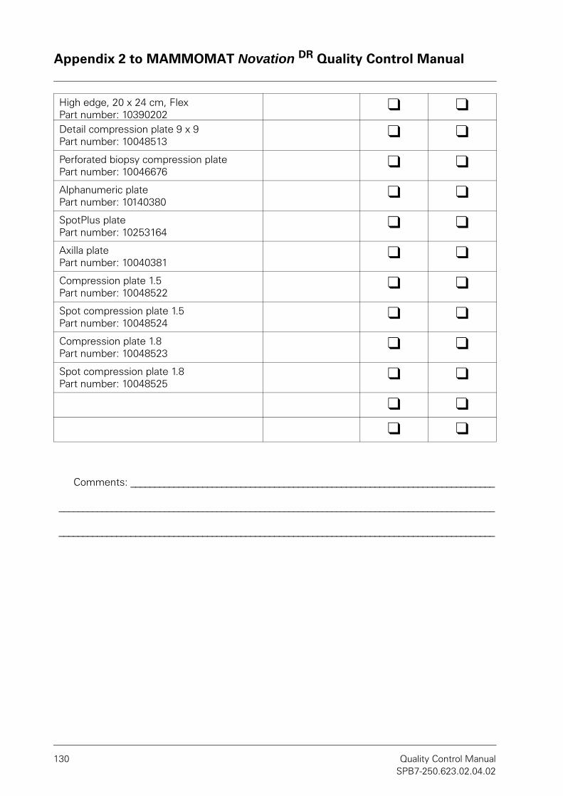
Appendix 2 to MAMMOMAT Novation DR Quality Control Manual
130 Quality Control ManualSPB7-250.623.02.04.02
High edge, 20 x 24 cm, FlexPart number: 10390202
l lDetail compression plate 9 x 9Part number: 10048513
l l
Perforated biopsy compression platePart number: 10046676
l l
Alphanumeric plate Part number: 10140380
l l
SpotPlus plate Part number: 10253164
l l
Axilla plate Part number: 10040381
l l
Compression plate 1.5Part number: 10048522
l l
Spot compression plate 1.5Part number: 10048524
l l
Compression plate 1.8Part number: 10048523
l l
Spot compression plate 1.8Part number: 10048525
l l
l l
l l
Comments: ____________________________________________________________________________
___________________________________________________________________________________________
___________________________________________________________________________________________

Appendix 2 to MAMMOMAT Novation DR Quality Control Manual
MAMMOMAT Novation DR 131SPB7-250.623.02.04.02
Test form Test 6: Collimator assessmentNOTE!NOTE!
Copy Appendix 1, record the measured values on the copy and file it together with this QC manual.
Collimator assessmentB is the deviation between radiation field and active detector area.
A is the deviation between radiation field and light field.
If B is positive, the X-ray field is larger than the detector area.
If B is negative, the X-ray field is smaller than the detector area.
If A is positive, the X-ray field is smaller than the light field.
If A is negative, the X-ray field is larger than the light field.
Site: ___________________________________________________
___________________________________________________
Room: ___________________________________________________
Type of test: ___________________________________________________
Performed by: ___________________________________________________
Date: ___________________________________________________

Appendix 2 to MAMMOMAT Novation DR Quality Control Manual
132 Quality Control ManualSPB7-250.623.02.04.02
Distances measured with large focal spot
Distances measured with small focal spot (optional)
Position F/A combi-nation
Value light field VLF (mm)
Value X-ray field VSF (mm)
Value detector field VDF (mm)
A = VSF - VLF (mm)
B = VDF - VLF (mm)
Chest wall edge (pos. 1)
Mo/Mo
Right edge (pos. 2)
Nipple-side edge (pos. 3)
Left edge (pos. 4)
Chest wall edge (pos. 1)
W/Rh
Right edge (pos. 2)
Nipple-side edge (pos. 3)
Left edge (pos. 4)
Position F/A combi-nation
Value light field VLF (mm)
Value X-ray field VSF (mm)
Value detector field VDF (mm)
A = VSF - VLF (mm)
B = VDF - VLF (mm)
Chest wall edge (pos. 1)
Mo/Mo
Right edge (pos. 2)
Nipple-side edge (pos. 3)
Left edge (pos. 4)
Chest wall edge (pos. 1)
W/Rh
Right edge (pos. 2)
Nipple-side edge (pos. 3)
Left edge (pos. 4)

Appendix 2 to MAMMOMAT Novation DR Quality Control Manual
MAMMOMAT Novation DR 133SPB7-250.623.02.04.02
Acceptance criteria:
Sum of absolute valuesright and left
Performance criteria
Large focal spot Small focal spot Passed Failed
Mo/Mo W/Rh Mo/Mo W/Rh
| Apos2 | + | Apos4 | (mm) ≤ 13 mm l l
Sum of absolute valuesnipple and chest
Performance criteria
Large focal spot Small focal spot Passed Failed
Mo/Mo W/Rh Mo/Mo W/Rh
| Apos1 | + | Apos3 | (mm) ≤ 13 mm l l
Sum of absolute valuesright and left
Performance criteria
Large focal spot Small focal spot Passed Failed
Mo/Mo W/Rh Mo/Mo W/Rh
| Bpos2 | + | Bpos4 | (mm) ≤ 13 mm l l
Sum of absolute valuesnipple and chest
Performance criteria
Large focal spot Small focal spot Passed Failed
Mo/Mo W/Rh Mo/Mo W/Rh
| Bpos1 | + | Bpos3 | (mm) ≤ 13 mm l l
Value on the nipple side Performance criteria
Large focal spot Small focal spot Passed Failed
Mo/Mo W/Rh Mo/Mo W/Rh
Bpos1 (mm) ≤ 5 mm l l
Comments: ____________________________________________________________________________
___________________________________________________________________________________________
___________________________________________________________________________________________

Appendix 2 to MAMMOMAT Novation DR Quality Control Manual
134 Quality Control ManualSPB7-250.623.02.04.02
For notes
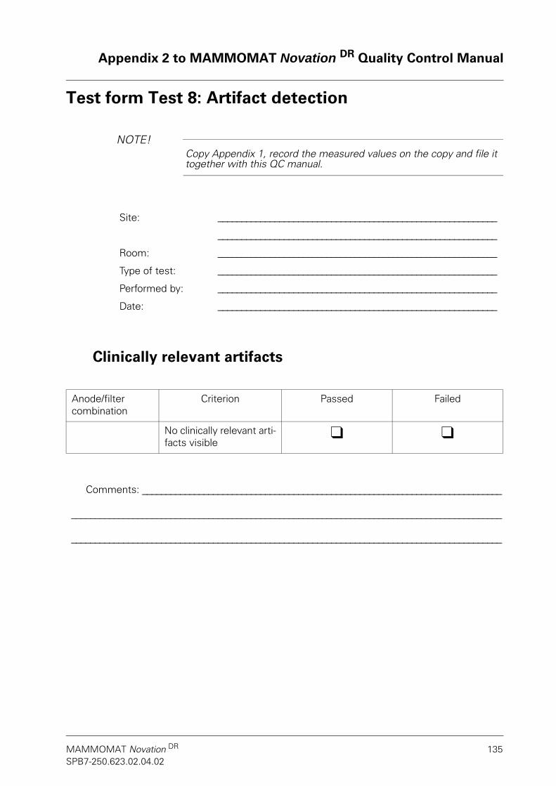
Appendix 2 to MAMMOMAT Novation DR Quality Control Manual
MAMMOMAT Novation DR 135SPB7-250.623.02.04.02
Test form Test 8: Artifact detection
NOTE!NOTE!Copy Appendix 1, record the measured values on the copy and file it together with this QC manual.
Clinically relevant artifacts
Site: ___________________________________________________________
___________________________________________________________
Room: ___________________________________________________________
Type of test: ___________________________________________________________
Performed by: ___________________________________________________________
Date: ___________________________________________________________
Anode/filter combination
Criterion Passed Failed
No clinically relevant arti-facts visible
l l
Comments: ____________________________________________________________________________
___________________________________________________________________________________________
___________________________________________________________________________________________

Appendix 2 to MAMMOMAT Novation DR Quality Control Manual
136 Quality Control ManualSPB7-250.623.02.04.02
For notes
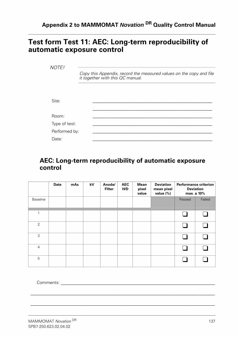
Appendix 2 to MAMMOMAT Novation DR Quality Control Manual
MAMMOMAT Novation DR 137SPB7-250.623.02.04.02
Test form Test 11: AEC: Long-term reproducibility of automatic exposure control
NOTE!NOTE!Copy this Appendix, record the measured values on the copy and file it together with this QC manual.
AEC: Long-term reproducibility of automatic exposure control
Site: ___________________________________________________________
___________________________________________________________
Room: ___________________________________________________________
Type of test: ___________________________________________________________
Performed by: ___________________________________________________________
Date: ___________________________________________________________
Date mAs kV Anode/Filter
AEC H/D
Mean pixel value
Deviation mean pixel value (%)
Performance criterionDeviation
max. ± 10%
Baseline Passed Failed
1 l l2 l l3 l l4 l l5 l l
Comments: ____________________________________________________________________________
___________________________________________________________________________________________
___________________________________________________________________________________________

Appendix 2 to MAMMOMAT Novation DR Quality Control Manual
138 Quality Control ManualSPB7-250.623.02.04.02
For notes
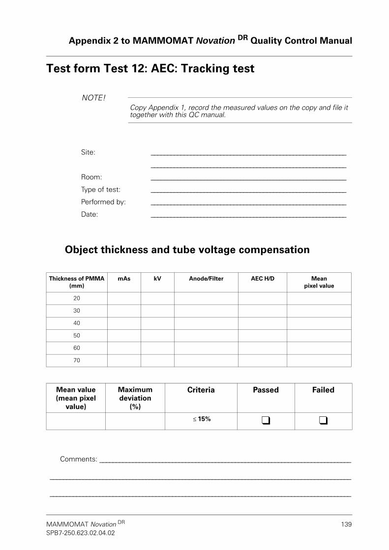
Appendix 2 to MAMMOMAT Novation DR Quality Control Manual
MAMMOMAT Novation DR 139SPB7-250.623.02.04.02
Test form Test 12: AEC: Tracking test
NOTE!NOTE!Copy Appendix 1, record the measured values on the copy and file it together with this QC manual.
Object thickness and tube voltage compensation
Site: ___________________________________________________________
___________________________________________________________
Room: ___________________________________________________________
Type of test: ___________________________________________________________
Performed by: ___________________________________________________________
Date: ___________________________________________________________
Thickness of PMMA (mm)
mAs kV Anode/Filter AEC H/D Mean pixel value
20
30
40
50
60
70
Mean value (mean pixel
value)
Maximum deviation
(%)
Criteria Passed Failed
≤ 15% l l
Comments: ____________________________________________________________________________
___________________________________________________________________________________________
___________________________________________________________________________________________

Appendix 2 to MAMMOMAT Novation DR Quality Control Manual
140 Quality Control ManualSPB7-250.623.02.04.02
For notes

Appendix 2 to MAMMOMAT Novation DR Quality Control Manual
MAMMOMAT Novation DR 141SPB7-250.623.02.04.02
Test form Test 13: Linearity and noise evaluation
NOTE!NOTE!Copy Appendix 1, record the measured values on the copy and file it together with this QC manual.
Site: ___________________________________________________________
___________________________________________________________
Room: ___________________________________________________________
Type of test: ___________________________________________________________
Performed by: ___________________________________________________________
Date: ___________________________________________________________

Appendix 2 to MAMMOMAT Novation DR Quality Control Manual
142 Quality Control ManualSPB7-250.623.02.04.02
Linearity
doffset = __________
NOTE!NOTE!The last 3 columns and the last row will help you calculate R2; if an ap-propriate computer program is used, the entries may be unnecessary.
Anoden/filter combination: __________ __________ kV
Exposure number:
mAs Mean pixel value
d
Air kerma K (mGy)
d2 K2 K•d
1 5
2 10
3 20
4 50
5 80
6 100
7 200
8 320
9 450
10 500
Mean valuedmean Kmean (d2)mean (K2)mean
(K•d)mean
Test Value Performancecriterion
Passed Failed
Linear correlation R2 ≥ 0.99 l l
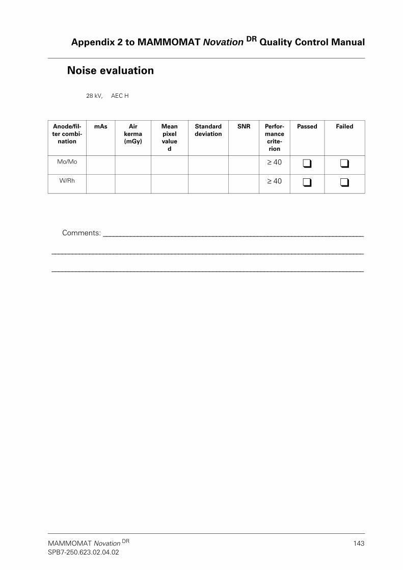
Appendix 2 to MAMMOMAT Novation DR Quality Control Manual
MAMMOMAT Novation DR 143SPB7-250.623.02.04.02
Noise evaluation
28 kV, AEC H
Anode/fil-ter combi-
nation
mAs Air kerma (mGy)
Mean pixel value
d
Standard deviation
SNR Perfor-mance crite-rion
Passed Failed
Mo/Mo ≥ 40 l lW/Rh ≥ 40 l l
Comments: ____________________________________________________________________________
___________________________________________________________________________________________
___________________________________________________________________________________________

Appendix 2 to MAMMOMAT Novation DR Quality Control Manual
144 Quality Control ManualSPB7-250.623.02.04.02
For notes

Appendix 2 to MAMMOMAT Novation DR Quality Control Manual
MAMMOMAT Novation DR 145SPB7-250.623.02.04.02
Test form Test 14: Detector uniformity
NOTE!NOTE!Copy this Appendix, record the measured values on the copy and file it together with this QC manual.
Site: ___________________________________________________________
___________________________________________________________
Room: ___________________________________________________________
Type of test: ___________________________________________________________
Performed by: ___________________________________________________________
Date: ___________________________________________________________
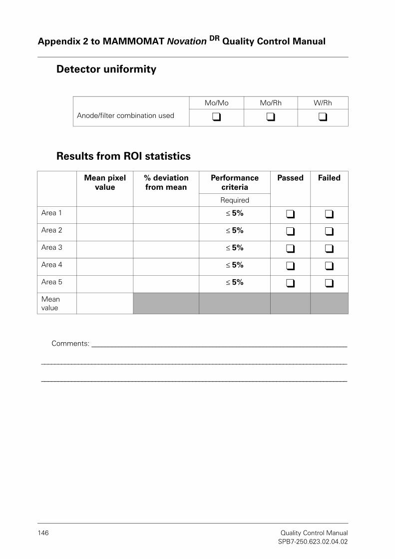
Appendix 2 to MAMMOMAT Novation DR Quality Control Manual
146 Quality Control ManualSPB7-250.623.02.04.02
Detector uniformity
Results from ROI statistics
Mo/Mo Mo/Rh W/Rh
Anode/filter combination used l l l
Mean pixel value
% deviation from mean
Performance criteria
Passed Failed
Required
Area 1 ≤ 5% l lArea 2 ≤ 5% l lArea 3 ≤ 5% l lArea 4 ≤ 5% l lArea 5 ≤ 5% l lMean value
Comments: ____________________________________________________________________________
___________________________________________________________________________________________
___________________________________________________________________________________________

Appendix 2 to MAMMOMAT Novation DR Quality Control Manual
MAMMOMAT Novation DR 147SPB7-250.623.02.04.02
Test form Test 15: Phantom image quality
NOTE!NOTE!Copy this Appendix, record the measured values on the copy and file it together with this QC manual.
Contrast resolution
Site: ___________________________________________________________
___________________________________________________________
Room: ___________________________________________________________
Type of test: ___________________________________________________________
Performed by: ___________________________________________________________
Date: ___________________________________________________________
Anode/Filter: _________
kV: _________
mAs: _________
Performance criteria
Passed Failed
Fibers ≥ 5 l lSpecks (Microcalci-fications)
≥ 4 l l
Masses ≥ 4 l l
Comments: ____________________________________________________________________________
___________________________________________________________________________________________
___________________________________________________________________________________________

Appendix 2 to MAMMOMAT Novation DR Quality Control Manual
148 Quality Control ManualSPB7-250.623.02.04.02
For notes
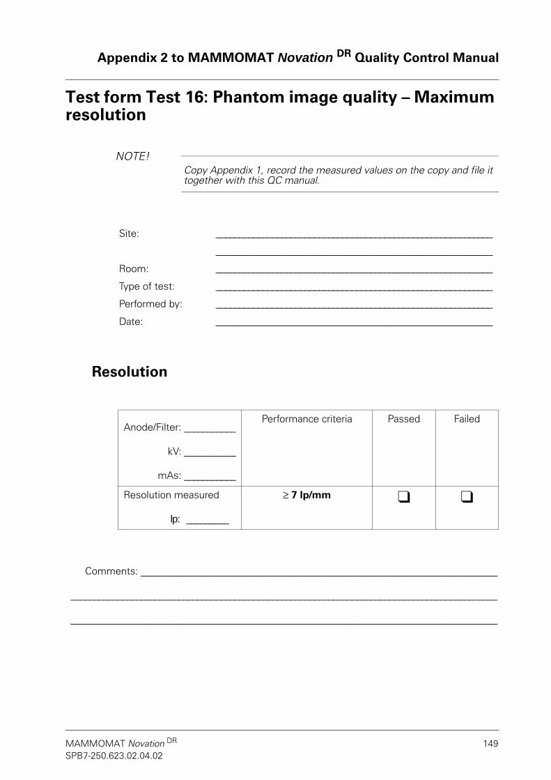
Appendix 2 to MAMMOMAT Novation DR Quality Control Manual
MAMMOMAT Novation DR 149SPB7-250.623.02.04.02
Test form Test 16: Phantom image quality – Maximum resolution
NOTE!NOTE!Copy Appendix 1, record the measured values on the copy and file it together with this QC manual.
Resolution
Site: ___________________________________________________________
___________________________________________________________
Room: ___________________________________________________________
Type of test: ___________________________________________________________
Performed by: ___________________________________________________________
Date: ___________________________________________________________
Anode/Filter: ___________
kV: ___________
mAs: ___________
Performance criteria Passed Failed
Resolution measured
lp: _________
≥ 7 lp/mm l l
Comments: ____________________________________________________________________________
___________________________________________________________________________________________
___________________________________________________________________________________________

Appendix 2 to MAMMOMAT Novation DR Quality Control Manual
150 Quality Control ManualSPB7-250.623.02.04.02
For notes

Appendix 2 to MAMMOMAT Novation DR Quality Control Manual
MAMMOMAT Novation DR 151SPB7-250.623.02.04.02
Test form Test 17: Mean glandular dose
NOTE!NOTE!Copy this Appendix, record the measured values on the copy and file it together with this QC manual.
Site: ___________________________________________________________
___________________________________________________________
Room: ___________________________________________________________
Type of test: ___________________________________________________________
Performed by: ___________________________________________________________
Date: ___________________________________________________________

Appendix 2 to MAMMOMAT Novation DR Quality Control Manual
152 Quality Control ManualSPB7-250.623.02.04.02
Prerequisites for calculating the mean glandular dose
Formula used:
D = K•g•c•s*
D Mean glandular dose
K Incident air kerma (without backscatter) at the upper surface of the PMMA
g Coupling factor between incident air kerma and mean glandular dose for a glandu-larity of 50% and for the Mo/Mo anode/filter combination
c Correction factor for deviations from the standard 50% glandularity
s Correction factor for anode/filter combinations other than Mo/Mo
The c and g factors are listed in the following table for different HVL values. They can be interpolated correspondingly for other HVL values. The values listed were derived from the typical breast thickness corresponding to a PMMA thickness of 50 mm on which the simulation calculation* is based.
* [D.R. Dance, C.L. Skinner, K.C. Young, J.R. Beckett. C.J. Kotre: Additional factors for the estimation of mean glandular breast dose using the UK mammography dosimetry protocolPhysics in Medicine and Biology 45, 3225-3240, 2000]
HVL (mm Al)
0.30 0.35 0.40 0.45 0.50 0.55 0.60
g factor 0.135 0.154 0.172 0.192 0.214 0.236 0.261
c factor 1.164 1.160 1.151 1.150 1.144 1.139 1.134
Mo/Mo Mo/Rh W/Rh
s factor 1.000 1.017 1.042

Appendix 2 to MAMMOMAT Novation DR Quality Control Manual
MAMMOMAT Novation DR 153SPB7-250.623.02.04.02
Mean glandular doseValues (at 28 kV) for the calculation
Calculation of the mean glandular dose
Anode/Filter mAs Air kerma(mGy)
HVL value (mm Al)
Mo/Mo
Mo/Rh
W/Rh
Anode/Filter
D = Kgcs (mGy) Performance criteria
Passed Failed
Mo/Mo
≤ 3.0 mGy
l lMo/Rh l lW/Rh l l
Comments: ____________________________________________________________________________
___________________________________________________________________________________________
___________________________________________________________________________________________

Appendix 2 to MAMMOMAT Novation DR Quality Control Manual
154 Quality Control ManualSPB7-250.623.02.04.02
For notes

Appendix 2 to MAMMOMAT Novation DR Quality Control Manual
MAMMOMAT Novation DR 155SPB7-250.623.02.04.02
Test form Test 18: Ghost image evaluation
NOTE!NOTE!Copy this Appendix, record the measured values on the copy and file it together with this QC manual.
Site: ________________________________________________
________________________________________________
Room: ________________________________________________
Type of test: ________________________________________________
Performed by: ________________________________________________
Date: ________________________________________________

Appendix 2 to MAMMOMAT Novation DR Quality Control Manual
156 Quality Control ManualSPB7-250.623.02.04.02
Ghost image evaluation
Offset = _______
Position Mean pixel value Ghosting factor(%)
PV1 PV2
1
2
3
4
Mean value ghost image factor (%)Performance
criteriaPassed Failed
< 3 % l l
Comments: ____________________________________________________________________________
___________________________________________________________________________________________
___________________________________________________________________________________________

Appendix 2 to MAMMOMAT Novation DR Quality Control Manual
MAMMOMAT Novation DR 157SPB7-250.623.02.04.02
Test form Test 19: AWS monitor checkNOTE!NOTE!
Copy this Appendix, record the measured values on the copy and file it together with this QC manual.
AWS monitor check and viewing conditions
Site: ________________________________________________
________________________________________________
Room: ________________________________________________
Type of test: ________________________________________________
Performed by: ________________________________________________
Date: ________________________________________________
Grayscale contrast: Yes No
5% square is visible inside 0% square
l l
Performance criteria: Yes
95% square is visible inside 100% square
l l
Performance criteria: Yes
Comments: ____________________________________________________________________________
___________________________________________________________________________________________
___________________________________________________________________________________________
Appendix 2 to MAMMOMAT Novation DR Quality Control Manual
158 Quality Control ManualSPB7-250.623.02.04.02
Spatial resolution: Yes No
All lines in all bar patterns can be differentiated
l l
Performance criteria: Yes
Comments: ____________________________________________________________________________
___________________________________________________________________________________________
___________________________________________________________________________________________
Visual inspection:
Yes No
Streaking l lPerformance criteria: No
Flicker l lPerformance criteria: No
Shadows l lPerformance criteria: No
Comments: ____________________________________________________________________________
___________________________________________________________________________________________
___________________________________________________________________________________________

Appendix 2 to MAMMOMAT Novation DR Quality Control Manual
MAMMOMAT Novation DR 159SPB7-250.623.02.04.02
Test form Test 20: Printer check
This test is required only if a laser camera and a printer are used.
NOTE!NOTE!Copy Appendix 2, record the measured values on the copy and file it together with this QC manual.
Site: ________________________________________________
________________________________________________
Room: ________________________________________________
Type of test: ________________________________________________
Performed by: ________________________________________________
Date: ________________________________________________

Appendix 2 to MAMMOMAT Novation DR Quality Control Manual
160 Quality Control ManualSPB7-250.623.02.04.02
Printer check
* LUT = Look-up table
Customer-specific values for "min. density" and "max. density"
Min. density
Max. density
Step Corr16b-bspline (LUT) Linear LUT*
Ref. LUT
Maximum density
Minimum density
Ref. density
Maximum density
Minimum density
1 0.20 0.23 0.17 0.20 0.23 0.17
2 0.34 0.38 0.30 0.52 0.56 0.49
3 0.47 0.51 0.43 0.86 0.90 0.82
4 0.64 0.69 0.59 1.18 1.23 1.13
5 0.81 0.87 0.75 1.52 1.58 1.46
6 1.05 1.12 0.99 1.84 1.91 1.78
7 1.31 1.38 1.24 2.18 2.25 2.11
8 1.66 1.74 1.58 2.52 2.60 2.44
9 2.10 2.19 2.01 2.85 2.94 2.77
10 2.68 2.77 2.59 3.18 3.27 3.08
11 3.50 3.60 3.40 3.50 3.60 3.40
Step MG1_5bCorr-bspline (LUT)
Ref. LUT Maximumdensity
Minimumdensity
1 0.20 0.23 0.17
2 0.44 0.48 0.40
3 0.68 0.72 0.64
4 0.94 0.99 0.89
5 1.18 1.24 1.12
6 1.45 1.52 1.39
7 1.73 1.80 1.66
8 2.01 2.09 1.93
9 2.32 2.41 2.23
10 2.73 2.82 2.64
11 3.50 3.60 3.40

Appendix 2 to MAMMOMAT Novation DR Quality Control Manual
MAMMOMAT Novation DR 161SPB7-250.623.02.04.02
* LUT = Look-up table
Step Corr16b-bspline (LUT)
Ref. LUT*
Recommenda-tion maximum
density
Recommenda-tion minimum
density
Required maximum
density
RequiredMinimumdensity
1 0.20 0.23 0.17 0.30 0.10
2 0.34 0.38 0.30 0.44 0.24
3 0.47 0.51 0.43 0.57 037
4 0.64 0.69 0.59 0.74 0.54
5 0.81 0.87 0.75 0.91 0.71
6 1.05 1.12 0.99 1.15 0.95
7 1.31 1.38 1.24 1.41 1.21
8 1.66 1.74 1.58 1.76 1.56
9 2.10 2.19 2.01 2.20 2.00
10 2.68 2.77 2.59 2.78 2.58
11 3.50 3.60 3.40 3.60 3.40
Step MG1_5bCorr-bspline (LUT)
Ref. LUT Recommenda-tion maximum
density
Recommenda-tion minimum
density
Required maximum
density
Required minimumdensity
1 0.20 0.23 0.17 0.30 0.10
2 0.44 0.48 0.40 0.54 0.34
3 0.68 0.72 0.64 0.68 0.58
4 0.94 0.99 0.89 1.04 0.84
5 1.18 1.24 1.12 1.28 1.08
6 1.45 1.52 1.39 1.55 1.35
7 1.73 1.80 1.66 1.83 1.53
8 2.01 2.09 1.93 2.11 1.91
9 2.32 2.41 2.23 2.42 2.22
10 2.73 2.82 2.64 2.83 2.63
11 3.50 3.60 3.40 3.60 3.40

Appendix 2 to MAMMOMAT Novation DR Quality Control Manual
162 Quality Control ManualSPB7-250.623.02.04.02
If your values do not meet the values specified above, then please refer to the printer manufacturer's quality control procedure. You can create your own baseline with the measured values resulting during the initial installation of the printer per the manufac-turer's QC procedure.
* OD = Optical density
Quality control manual of printer manufacturer complied with:
SMPTE [%] Step Measured OD* Passed Failed
100 1 l l90 2 l l80 3 l l70 4 l l60 5 l l50 6 l l40 7 l l30 8 l l20 9 l l10 10 l l0 11 l l
Compliance Yes No
Date _______________ l lDate _______________ l lDate _______________ l l
Comments: ____________________________________________________________________________
___________________________________________________________________________________________
___________________________________________________________________________________________


Order No.: SPB7-250.623.02.04.02Printed in GermanyAG 09/07
© Siemens AG 2007All rights reserved
Contact address:
Siemens AG Siemens AG, Medical SolutionsWittelsbacherplatz 2 Special SystemsD-80333 Muenchen Henkestraße 127Germany D-91052 Erlangen
Germany