provision of 3g mobile services in sparsely populated ... of 3g mobile services in sparsely...
TRANSCRIPT

RADIOENGINEERING, VOL. 17, NO. 1, APRIL 2008 43
Provision of 3G Mobile Services in Sparsely Populated Areas Using High Altitude Platforms
Jaroslav HOLIŠ, Pavel PECHAČ
Dept. of Electromagnetic Field, Czech Technical University in Prague, Technická 2, 166 27 Praha, Czech Republic
[email protected], [email protected]
Abstract. This paper deals with the application of High Altitude Platforms for the provision of third generation mobile services in sparsely-populated areas or in de-veloping countries. It focuses on the behavior of large cells provided via a multiple HAP deployment and shows the possibilities of using small cells located inside these large cells to serve hot-spot areas. The impact of the different types of HAP antenna masks and their adjustment on cell capacity and the quality of coverage is presented. The main parameter of the antenna radiation pattern under investigation is the power roll-off at the cell edge. Optimal values of this parameter are presented for different sce-narios. Simulations of system level parameters were based on an iteration loops approach.
Keywords High Altitude Platforms (HAPs), UMTS, Antennas, 3G Mobile services.
1. Introduction The increasing demand for high-speed mobile internet
has lead to a massive development in mobile systems. Commercially-available devices are commonly accessible for transmission to mobile stations in a downlink direction based on High Speed Downlink Packet Access (HSDPA), with an ideal speed of up to 14.4 Mpbs [1]. High Speed Uplink Data Access (HSUPA) technology, ideally enabling a data rate in an uplink direction of up to 5.76 Mbps [2], [3] will become commercially available in the near future. A major problem hindering the spread of 3G, or the current 3.5G, mobile services beyond metropolitan or wealthy regions is the cost of building the network, because 3G mobile systems offer a smaller range than 2G mobile net-works with a frequency band of around 2.0 GHz and a new access method to radio interfaces, which means that 3G networks require a denser network of masts.
HAPs situated in the stratosphere at an altitude rang-ing from 17 to 22 km [4] offer many advantages when compared to terrestrial base stations, such as a larger area of coverage and no shadowing for high elevation angles.
The main advantage of HAPs as against satellites is the link budget, due to their altitude of around 20 km and their quasi-stationary position. The spectrum allocated for HAPs by ITU worldwide is around 48 GHz [5]. [6] says that HAP stations may be used as base stations within the terrestrial component of IMT-2000 in the 1.885-1.980 GHz, 2.010 to 2.025 GHz and 2.110-2.170 GHz bands in Regions 1 (Europe, Africa). HAPs could be used as an alternative to a terrestrial component for third generation mobile networks such as the Universal Mobile Telecommunication System (UMTS), or could be a complementary element for terres-trial networks. The coverage of extensive and sparsely populated areas by 3G mobile network signals is compli-cated and extremely expensive. A solution to this problem could be the use of HAPs, which offer an excellent pro-spective, and not only for developing countries.
The studies introduced in the following sections were divided into two basic scenarios. The first scenario in-volved a study where a single HAP provided one large cell and the HAPs were situated in a hexangular deployment. In the case of the second scenario, hot-spot areas (for example villages) were modeled within the large cells. Fig. 1 illus-trates the composite Free Space Loss (FSL) for HAP sta-tions located in a hexangular deployment above the Czech Republic (37 cells with a service area radius equal to 30 km above the Czech Republic). These HAPs were assumed to be at an altitude of 22 km.
Fig. 1. The composite Free Space Loss for 37 HAPs with a
service area radius of 30 km in the Czech Republic.
Fig. 2 shows the number of HAPs as a function of the service area radius of a single HAP. This service area could be formed by one cell or by multiple cells provided via a single HAP, particularly if elliptical antenna beams are used [7].

44 J. HOLIŠ, P. PECHAČ, PROVISION OF 3G MOBILE SERVICES IN SPARSELY POPULATED AREAS USING HAPS
Fig. 2. Number of HAPs required to cover the Czech Republic
as a function of the service area radius.
2. Parameters of the Simulation Scenarios As it was mentioned above, the studies were divided
into two basic scenarios. The first scenario involved a study where a single HAP provided one large cell and the HAPs were deployed in a hexangular arrangement. In the second scenario small hot-spot cells were modeled within a large cell in order to simulate villages or other areas with a high demand for capacity.
2.1 Propagation Prediction A Free Space Loss (FSL) model was used for the ba-
sic propagation prediction. An additional log-normal fade margin of 8 dB for suburban area was applied to give a more accurate approach in order to simulate the slow fad-ing [2]. The FSL model in dB [8] applied for the basic approach of propagation prediction for HAPS is defined as
4.92)log(20)log(20 ++= GHzkmFSL fdL (1)
where fGHZ is the carrier frequency in GHz and dkm, is the distance between a platform and a user in km. In the case of the second scenario, hot-spot areas (for example vil-lages) were modeled within the large cells. The modeling of these areas was based on an empirical model of fade margin for satellites. The additional propagation loss in dB is then a function of the elevation angle [9]:
BpALM += )ln(. (2)
where p is the percentage outage probability in the range of 1 – 20%. Coefficients A and B are defined as follows
fA 2.07.015.0002.0 2 −−Φ−Φ= , (3)
Φ−+= 33.05.12.27 fB (4)
where Φ is the elevation angle in degrees and f is the fre-quency in GHz. For the results presented here an outage
probability of 1% was used and so the fade margin is in the range from 30 dB (for the low elevation angles) to 0.5 dB (for an elevation angle of 90 degrees). The addi-tional fade margin was normalized with random distribu-tion between 0 – 1 in order to create a more realistic approach.
The curvature of the Earth can be neglected for a coverage radius less than 100 km [10].
2.2 HAP Antenna Radiation Pattern In the case of HAPs the cell shape can be modeled
using an antenna radiation pattern. In addition, the fre-quency reuse factor for UMTS systems is equal to 1 and so the antenna radiation pattern of an HAP station can isolate the cell. The simulation scenarios focused on the impact of the antenna radiation pattern on the system level parame-ters. The HAP antenna parameter under investigation was the antenna power roll-off. The antenna power roll-off means the difference between the peak antenna gain at the nadir and the gain at the cell edge.
Antenna radiation patterns were based on [6] and [11]. In the case of the ITU-R antenna mask, the gain of the main lobe (dBi) can be modeled as a function of the angle θ (degree) from the main beam direction as follows [6]
( ) 3( )mb
G G θθθ
= − (5)
where Gm is the maximum gain in the main lobe (dBi) and θb (degree) is one-half the 3 dB beamwidth, which can be estimated by
0.1
744210 mb Gθ = . (6)
Based on (5) and (6) the maximum gain as a function of antenna power roll-off (dB) can be calculated as follows
7442( ) 10 log( )3m
ce
roll offG roll offθ
⋅ −− =
⋅ (7)
where θce (degree) is the angle between the main beam direction and the cell edge.
The second approximation of antenna radiation pattern used for the simulations presented here is derived from the cosine function raised to the power of n [12]. The antenna gain then can be modeled as follows
2
32 ln 2( ) 10 log( max((cos ) , ))12(2arccos( ))2
n
n
G sllθ η θ= (8)
where sll is the flat side lobe level, η is the antenna gain efficiency (for the results presented here η is equal to 1) and n defines the rate of power roll-off of the main lobe. The power of n [11] can be easily calculated as follows

RADIOENGINEERING, VOL. 17, NO. 1, APRIL 2008 45
10
10( )log (cos( ))ce
roll off
n roll offθ
−−
− = . (9)
For antennas modeled based on [11], flat side lobes at a –40 dB level relative to the maximum gain were used. For the small cells, where the cell center is sideways to the HAPs position, elliptical beams were used [7], [11] as well. The elliptical beam antennas can provide a circular gain footprint on the ground independently of the HAP and cell center position. The classical circular beam is projected to the elliptical gain footprint on the ground with a decreasing elevation angle.
Examples of antenna radiation patterns with power roll-off of 10 dB at the cell edge are depicted in Fig. 3. This figure presents a comparison of an antenna pattern with a flat side lobe level and ITU-R antenna radiations pattern [6] for cell radii of 3 and 30 km. The angle of boresight at the cell edge for a cell radius of 30 km and HAPs situated at an altitude of 22 km is equal to 53.75 degrees and for a cell radius of 3 km the angle of boresight is equal to 7.77 degrees.
Fig. 3. Antenna pattern as a function of the angle θ from
boresight.
2.3 Parameters of Simulations The simulations were accomplished using computa-
tional methods based on iterative loops. A detailed de-scription is given in [2] and their application for terrestrial systems was presented in [13]. 150 users per cell were randomly distributed in the target area. The Vehicular A channel model from the ITU-R recommendation was the pick-up for the simulations presented in suburban and rural areas [14]. The results are shown as a function of system-level parameters on the antenna power roll-off at the cell edge. An uplink loading of 60% was allowed for simula-tions of cells with a radius of 30 km and of 90% for cells with a radius of 3 km. The power level limit of the large cell base station was set as for a typical terrestrial macro-cell base station and for the power limit of the hot-spot base station we allowed the equivalent of a typical terres-trial micro-cell base station [2]. The mobile stations
utilized an omnidirectional antenna with a gain of 0 dBi. A maximum transmission power of 125 mW was allowed for the mobile station.
3. Multi HAP Deployment with a Single Large Cell This scenario was modeled with 61 cells in a ho-
mogenous hexangular deployment with a radius of 30 km. This radius is typically used as the radius of a HAP service area in most works dealing with HAPs. The 30 km cell radius seems to provide a trade-off between the cell ca-pacity and quality of coverage. There are problems with the link budget for larger cells, because the HAP wide-beam-width antennas do not offer sufficient gain (see Fig. 3). There is an insufficient power margin due to increasing FSL and shadowing effects for lower elevation angles, especially for high speed data services.
Fig. 4 illustrates the probability of coverage as a function of antenna power roll-off at the cell edge for cosn and an ITU-R antenna mask. The antenna power roll-off at the cell edge changed in the range from 3 to 20 dB. Fig. 5 shows the average cell capacity (the number of users with voice service). From Fig. 4 and Fig. 5 it is obvious that the optimal antenna power roll-off at the cell edge must be a trade-off between quality of coverage and cell capacity. For higher roll-off the cells are more isolated at the expense of quality of coverage at the cell edge. The cosn antenna model offers better system parameters in comparison to the ITU-R antenna mask, because for a cell radius of 30 km the mask has lower antenna gain at the cell edge and, particularly, a steeper trend after the cell edge (at 54 degrees for a cell radius of 30 km) thereby having a lower interference impact on neighboring cells.
A 10 dB antenna power roll-off for large cells was selected for the next scenarios, with hot-spot cells within these large cells having a radius of 30 km.
Fig. 4. Uplink quality of coverage for range services and different antenna masks.

46 J. HOLIŠ, P. PECHAČ, PROVISION OF 3G MOBILE SERVICES IN SPARSELY POPULATED AREAS USING HAPS
Fig. 5. Number of users served per cell.
4. Hot-Spot Cells An additional 10 cells with a radius of 3 km were
situated within the large 30 km radius cells. These cells are designed to simulate villages or other hot-spot areas with higher capacity requirements (see Fig. 6). The additional fade margin modeling the suburban area was calculated as a function of the elevation angle [9]. Antennas with ellipti-cal and circular beams were focused on these cells. Their roll-off factor at the cell edge changed in the 1 to 30 dB range. The study was divided into two cases. In the first case, the same carrier frequency was used for both the small and large cells. In the second, the small cells used a different carrier frequency (each UMTS operator should have 3 carriers). In the next section, the results of the sys-tem level simulations will be presented for different antenna types in one graph for both the single and two carriers simulation scenarios.
Fig. 6. Composite path loss including antenna gain of 10 hot-spot cells of 3 km radius with elliptical beams inside a large cell with a 30 km radius.
4.1 Cosn Antenna Mask In this simulation scenario the large cell with a cell
radius of 30 km was modeled using a cosn antenna mask and the 10 small cells were located within this large cell in order to serve the hot-spot areas. The small cells were modeled based on a cosn antenna mask using elliptical and circular beams with a flat side lobe.
4.1.1 Elliptical Antenna Beams
Elliptical antenna beams can provide circular gain footprints on the ground independently of the HAP and cell center positions (see Fig. 6). The directivity of the elliptical antenna beams was calculated according to the methods described in [11]. The impact of the antenna power roll-off of small cells on their capacity is shown in Figs. 7 and 8.
Fig. 7. Number of users served per cell.
Fig. 8. Other-to-own cell interference ratio in the uplink.
From Figs. 7 and 8, an optimal roll-off at the cell edge in the range between 3 – 7 dB can be distinguished. The lower value in comparison with the multiple HAP study is caused by the fact that the hot-spot cells are not in a ho-mogenous hexangular deployment and so interference is not such a crucial parameter as in the case of multi-HAP hexangular deployment. The different carriers of small and large cells particularly impact large cells. There is an aver-age cell capacity of about 33 users for the large cell (almost
RADIOENGINEERING, VOL. 17, NO. 1, APRIL 2008 47
50% less – see Fig. 5) in the case of single carrier fre-quency. In the case of two carriers the cell capacity of the large cell is almost the same as in the scenario without the small cells.
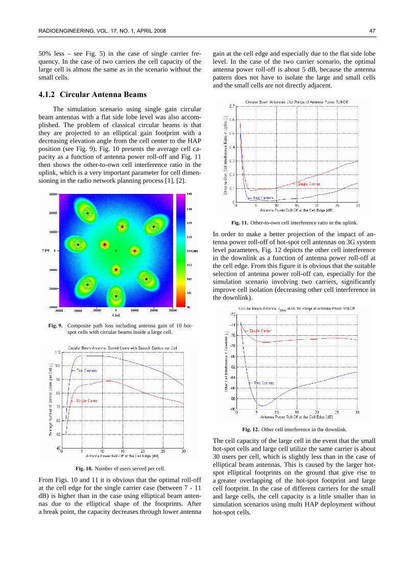
4.1.2 Circular Antenna Beams
The simulation scenario using single gain circular beam antennas with a flat side lobe level was also accom-plished. The problem of classical circular beams is that they are projected to an elliptical gain footprint with a decreasing elevation angle from the cell center to the HAP position (see Fig. 9). Fig. 10 presents the average cell ca-pacity as a function of antenna power roll-off and Fig. 11 then shows the other-to-own cell interference ratio in the uplink, which is a very important parameter for cell dimen-sioning in the radio network planning process [1], [2].
Fig. 9. Composite path loss including antenna gain of 10 hot-
spot cells with circular beams inside a large cell.
Fig. 10. Number of users served per cell.
From Figs. 10 and 11 it is obvious that the optimal roll-off at the cell edge for the single carrier case (between 7 - 11 dB) is higher than in the case using elliptical beam anten-nas due to the elliptical shape of the footprints. After a break point, the capacity decreases through lower antenna
gain at the cell edge and especially due to the flat side lobe level. In the case of the two carrier scenario, the optimal antenna power roll-off is about 5 dB, because the antenna pattern does not have to isolate the large and small cells and the small cells are not directly adjacent.
Fig. 11. Other-to-own cell interference ratio in the uplink.
In order to make a better projection of the impact of an-tenna power roll-off of hot-spot cell antennas on 3G system level parameters, Fig. 12 depicts the other cell interference in the downlink as a function of antenna power roll-off at the cell edge. From this figure it is obvious that the suitable selection of antenna power roll-off can, especially for the simulation scenario involving two carriers, significantly improve cell isolation (decreasing other cell interference in the downlink).
Fig. 12. Other cell interference in the downlink.
The cell capacity of the large cell in the event that the small hot-spot cells and large cell utilize the same carrier is about 30 users per cell, which is slightly less than in the case of elliptical beam antennas. This is caused by the larger hot-spot elliptical footprints on the ground that give rise to a greater overlapping of the hot-spot footprint and large cell footprint. In the case of different carriers for the small and large cells, the cell capacity is a little smaller than in simulation scenarios using multi HAP deployment without hot-spot cells.

48 J. HOLIŠ, P. PECHAČ, PROVISION OF 3G MOBILE SERVICES IN SPARSELY POPULATED AREAS USING HAPS
4.2 ITU-R Antenna Mask Large cells were modeled using an ITU-R antenna
mask with a cell edge roll-off of 10 dB. The ITU-R an-tenna mask is a classic circular antenna radiation pattern that becomes more and more projected with decreasing elevation angles from the cell center, to create an increas-ingly elliptical footprint on the ground. Fig. 13 shows the cell capacity for ranges of antenna power roll-off at the cell edge. In comparison with the cosn antenna model scenario, the cell capacity only gradually decreases after break point. This is the result of the very low side lobe level (-73 dB to the peak gain). In case of single carrier frequency, the cell capacity of the large cell is lower (about 31 users per cell), because there is more overlapping of the main lobes (see Fig. 9).
Fig. 13. Number of users served per cell.
Fig. 14. Other-to-own cell interference ratio in the uplink.
The lower value of the other-to-own cell interference ratio than in the previous scenarios is distinguishable from Fig. 14 in comparison with Fig. 8 and Fig. 11. This is also
caused by a very low side lobe level. The optimal antenna power roll-off at the cell edge for the single carrier sce-nario is about 12 dB and for the two carriers scenario about 5 dB.
5. Discussion Fig. 1 shows the HAPs in homogenous hexangular
deployment above the Czech Republic. HAPs will proba-bly offer greater prospects for developed, and especially for small, countries in the case of a disaster, because they could be deployed very fast – within a matter of hours. However, the application of HAPs is probably more attrac-tive for geographically extensive and developing countries, for example in Africa. HAP stations could provide mobile and fixed wireless services with the range of one HAP service area having a radius of hundreds of kilometers.
Fig. 15 illustrates the composite FSL for HAP stations located in a hexangular deployment above Africa. Fig. 16 shows the number of HAPs as a function of the service area radius of a single HAP.
Fig. 15. Composite Free Space Loss for 339 HAPs with a service
area radius of 200 km in Africa.
It was shown that for large cells with a radius of 30 km in a homogenous hexangular deployment, the value of antenna power roll-off is a trade-off between the cell capacity and the quality of coverage. A steep roll-off can guarantee excellent cell isolation, but at the expense of high quality coverage. Small cells were also distributed within the large cells to simulate hot-spot areas with additional path loss as a function of the elevation angle. For these small cells that are not directly adjacent the optimal antenna power roll-off is about 5 dB for elliptical beam antennas and about 5 -12 dB for classical circular beam antennas.

RADIOENGINEERING, VOL. 17, NO. 1, APRIL 2008 49
Fig. 16. Number of HAPs required to cover Africa as a function
of the service area radius.
6. Conclusion The possibilities offered by High Altitude Platforms
for the provision of 3G mobile services in sparsely popu-lated areas were presented. While the maximum terrestrial UMTS cell radius in rural or suburban areas is about 3 km, a HAP 3G cell radius of 30 km can be successfully pro-vided. Suitable adjusted HAP antenna radiation patterns can decrease other cell interference (the other-to-own cell interference ratio in the uplink i can be lower than the typi-cal terrestrial value of 0.55) thereby increasing cell ca-pacity. Simulations proved that small cells can be success-fully distributed within the large cells to cover hot-spot areas. The application of different carriers for large cells and hot-spot cells can significantly increase cell capacity, especially for the large cells.
Acknowledgements This work was supported in part by the Czech Minis-
try of Education, Youth and Sports within the framework of the OC092 - COST Action 297 and MSM 6840770014 projects.
References [1] HOLMA, H., TOSKALA, A. WCDMA for UMTS – HSPA Evolution
and LTE. 4th ed., John Wiley & Sons, 2007.
[2] LAIHO, J., WACKER, A. NOVOSAD, T., Radio Network Planning and Optimization for UMTS. 2nd ed., John Wiley & Sons, 2005.
[3] HOLMA, H., TOSKALA, A. HSDPA/HSUPA for UMTS: High Speed Radio Access for Mobile Communications. John Wiley & Sons, 2006.
[4] TOZER, T. C., GRACE, D. High-altitude platforms for wireless communications. IEE Electron. Commun. Eng. J., June 2001, vol. 13, no. 3, pp.127-137.
[5] Preferred characteristics of systems in the fixed service using high- altitude platform stations operating in the bands 47.2–47.5 GHz and 47.9–48.2 GHz. Int. Telecommunications Union, Recommendation ITU-R F.1500, 2000.
[6] Minimum performance characteristics and operational conditions for high altitude platform stations providing IMT-2000 in the Bands 1885–1980 MHz, 2010–2025 MHz and 2110–2170 MHz in the Regions 1 and 3 and 1885–1980 MHz and 2110–2160 MHz in Region 2. Int. Telecommunications Union, Recommendation ITU- R M.1456, 2000.
[7] HOLIS, J., PECHAC, P., Simulation of UMTS networks provided via HAP stations using elliptical and circular beam antennas in urban and suburban areas. In Proceedings of the 9th International Symposium Wireless Personal Multimedia Communications – WPMC’06. San Diego (USA), September 2006, p. 348-351.
[8] SAUNDERS, S. R., ARGO-ZAVALA, A. Antennas and Propagation for Wireless Communication Systems. 2nd ed., John Wiley & Sons, 2007.
[9] PARKS, M. A. N., EVANS, B. G., BUTT, G. High elevation angle propagation results applied to a statistical model and an enhanced empirical model. IEE Electronics Letters, September 1993, vol.29, no.19, p. 1723-1725.
[10] AXIOTIS, D. I., THEOLOGOU, M. E. An empirical model for predicting building penetration loss at 2 GHz for high elevation angles. IEEE Antennas and Wireless Propagation Letters, 2003, vol. 2, pp. 234-237.
[11] THORTON, J., GRACE, D., CAPSTICK, M. H., TOZER, T. C. Optimizing an array of antennas for cellular coverage from a high altitude platform. IEEE Trans. Commun., May 2003, vol. 2, pp. 484-to 492.
[12] BALANIS, C. A. Antenna Theory, Analysis and Design. 2nd ed., John Wiley & Sons, 1997.
[13] HOLIS, J., PECHAC, P. Simulation of UMTS capacity and quality of coverage in urban macro- and microcellular environment. Radioengineering, December 2005, vol. 14, no. 4, pp. 21-26.
[14] Guidelines for evaluation of radio transmission technologies for IMT-2000. Int. Telecommunications Union, Recommendation ITU-R M.1225, 1997.
About Authors... Jaroslav HOLIŠ received his M.Sc. degree in radio electronics from the Czech Technical University in Prague, Czech Republic, in 2005. He is currently a Ph.D. student at the Department of Electromagnetic Field at the Czech Technical University in Prague. His research interests are focused on the physical layer of 3G and 4G mobile systems and on radio wave propagation.
Pavel PECHAČ received his M.Sc. degree and Ph.D. in radio electronics from the Czech Technical University in Prague, Czech Republic, in 1993 and 1999 respectively. He is currently a Professor at the Department of Electromagnetic Field, the Czech Technical University in Prague. His research interests lie in the field of radio wave propagation and wireless systems.