proposed demolition plan ellwood marine terminal ... · proposed demolition plan ellwood marine...
TRANSCRIPT

Proposed Demolition Plan
Ellwood Marine Terminal Decommissioning
January 2013
Prepared for: Venoco, Inc.
6267 Carpinteria Avenue, Suite 100 Carpinteria, CA 93013
Prepared by:
4567 Telephone Road, Suite 203 Ventura, CA 93003

Proposed Demolition Plan
Ellwood Marine Terminal Decommissioning
Prepared for
Venoco, Inc. 6267 Carpinteria Avenue, Suite 100
Carpinteria, CA 93013
Prepared by
4567 Telephone Road, Suite 203 Ventura, CA 93003
Project No. 450-061
January 2013


EMT Decommissioning - Demolition Plan i
TABLE OF CONTENTS
1.0 PROJECT OVERVIEW ............................................................................................................. 1-1
1.1 Site Background ................................................................................................................. 1-1
1.2 Site Geology and Hydrogeology ......................................................................................... 1-3
1.3 Previous Environmental Investigations .............................................................................. 1-4
2.0 DEMOLITION ACTIVITIES ....................................................................................................... 2-1
2.1 Demolition Preparation ..................................................................................................... 2-1
2.1.1 Pre-demolition Geophysical Survey .......................................................................... 2-2 2.1.2 Pre-demolition Sampling (Tier 1 Screening) .............................................................. 2-2 2.1.3 Hazardous Material Removal .................................................................................... 2-3 2.1.4 Health and Safety ...................................................................................................... 2-3 2.1.5 Archaeology and Cultural Awareness ....................................................................... 2-4 2.1.6 Hot Work Procedures ................................................................................................ 2-4 2.1.7 Dust Control .............................................................................................................. 2-4 2.1.8 Personnel and Logistics ............................................................................................. 2-5 2.1.9 Site Controls .............................................................................................................. 2-5 2.1.10 Equipment Requirements ......................................................................................... 2-6
2.2 Equipment and Material Removal ..................................................................................... 2-6
2.2.1 Structure Removal ..................................................................................................... 2-6 2.2.2 Surface Piping Removal ............................................................................................. 2-7 2.2.3 Loading Line Removal ................................................................................................ 2-7 2.2.4 Tank Removal .......................................................................................................... 2-13 2.2.5 Underground Piping Grouting ................................................................................. 2-13 2.2.6 Miscellaneous Materials Removal........................................................................... 2-13
2.3 Transportation ................................................................................................................. 2-13
2.4 Waste Disposition ............................................................................................................ 2-14
3.0 PROPOSED DEMOLITION SCHEDULE ..................................................................................... 3-1

Table of Contents
ii EMT Decommissioning – Demolition Plan
FIGURES AND ATTACHMENTS
Figure 1-1 Site Vicinity Map ...................................................................................................................... 1-2 Figure 1-2 Site Location Map..................................................................................................................... 1-3 Attachment 1 Geophysical Survey – Underground Pipelines
ACRONYMS AND ABBREVIATIONS
bbl barrel bgs below ground surface BMPs Best Management Practices CPT cone penetrometer technique (or test) EMT Ellwood Marine Terminal EOF Ellwood Onshore Facility FPD Fire Protection Division FRC flame resistant clothing JSA job safety analysis LACT leased automatic custody transfer LBP lead based paint LEL lower-explosive limit LACT leased automatic custody transfer OSHA Occupational Safety and Health Administration PAH polycyclic aromatic hydrocarbons PCB polychlorinated biphenyls PLEM pipeline-end manifold PM Project Manager PPE personal protection equipment PPLP Plains Pipeline Limited Partnership ppm parts per million psi Pounds per square inch ROW Right of Way SLC (California) State Lands Commission SBBM San Bernardino Base Meridian SSO Site-Safety Officer TPH total petroleum hydrocarbons TRPH total recoverable petroleum hydrocarbons UCSB University of California, Santa Barbara VOC volatile organic compounds
1 PROJECT OVERVIEW
EMT Decommissioning - Demolition Plan 1-1
Venoco Inc. (Venoco) proposes to decommission its idled oil storage and transport facilities at Ellwood Marine Terminal (EMT). The EMT facilities are no longer needed because oil is directly transported from the Ellwood Onshore Facility (EOF) to the Plains All American Pipeline, L.P. Coastal Pipeline at Las Flores Canyon.
As part of the EMT decommissioning, Venoco must submit a Demolition and Reclamation (D&R) Permit application, which includes this Demolition Plan. The permit application provides detail on demolition and reclamation activities that have the potential of impacting the environment. Decommissioning of the EMT will be in accordance with Section 35.170.3 of County of Santa Barbara, Article II Coastal Zoning Ordinance and active lease agreements that refer to the restoration and re-vegetation of the EMT site to a “natural condition” within seven years of the issue date of the D&R permit. The University of California Santa Barbara (UCSB) Long Range Development Plan – Vision 2025 (draft, March 2008; as amended), which also serves as UCSB’s Local Coastal Program, states that the EMT property is to be designated as open space upon termination of the current lease in 2016.
The demolition process includes the removal, possible treatment, and recycling of identified EMT equipment and facilities, along with handling and disposal of any non-hazardous and/or hazardous waste generated from demolition activities. Equipment and facilities identified for removal consist of existing aboveground structures (e.g., tanks, pipelines, buildings, utility poles, fencing) and some (but not all) underground piping. In addition, several plant species of nuisance and/or invasive plants will be removed, and the containment berms and other modified areas within the EMT boundaries will be topographically re-contoured. Anticipated activities are designed to mitigate potential negative impacts to annual grassland, native grassland, and wetland resources from demolition and re-contouring of the EMT.
1.1 Site Background
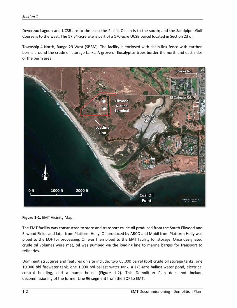
In August 1929, the Bankline Oil Company leased the land on which the onshore improvements associated with Venoco’s EMT are located. The first improvements, including two oil storage tanks, were made by Burmah Oil Company (now Phillips Petroleum Company) in 1929. The onshore land is located adjacent to the Pacific Ocean, 0.75 mile (1.2 kilometers [km]) northwest of Coal Oil Point in Santa Barbara County, California, approximately 1 mile (1.6 km) west of the intersection of Storke and El Colegio Roads (Figure 1-1). The property is owned by UCSB, and for restoration purposes, covers 17.54 acres encompassing the EMT facilities and a pipeline easement (loading line). The loading line extends aboveground approximately 650 feet from the southern boundary of the EMT property, southwest (230°) to the bluff where it becomes buried. In 1997, Venoco acquired the tenant rights under the lease with respect to the EMT. The offshore portion of the EMT is leased to Venoco pursuant to the State Lease PRC 3904.1 and is not part of this evaluation. The UCSB lease will expire in 2016, and the onshore portion of the EMT must be abandoned and returned to a natural condition.
The EMT property is located in Santa Barbara County, south of the city of Goleta, southwest of the intersection of Highway 101 and Hollister Avenue. Ocean Meadows Golf Course is to the north;
Section 1
1-2 EMT Decommissioning - Demolition Plan
Devereux Lagoon and UCSB are to the east; the Pacific Ocean is to the south; and the Sandpiper Golf Course is to the west. The 17.54-acre site is part of a 170-acre UCSB parcel located in Section 23 of
Township 4 North, Range 29 West (SBBM). The facility is enclosed with chain-link fence with earthen berms around the crude oil storage tanks. A grove of Eucalyptus trees border the north and east sides of the berm area.
Figure 1-1. EMT Vicinity Map.
The EMT facility was constructed to store and transport crude oil produced from the South Ellwood and Ellwood Fields and later from Platform Holly. Oil produced by ARCO and Mobil from Platform Holly was piped to the EOF for processing. Oil was then piped to the EMT facility for storage. Once designated crude oil volumes were met, oil was pumped via the loading line to marine barges for transport to refineries.
Dominant structures and features on site include: two 65,000 barrel (bbl) crude oil storage tanks, one 10,000 bbl firewater tank, one 1,000 bbl ballast water tank, a 1/3-acre ballast water pond, electrical control building, and a pump house (Figure 1-2). This Demolition Plan does not include decommissioning of the former Line 96 segment from the EOF to EMT.

Section 1
EMT Decommissioning - Demolition Plan 1-3
Figure 1-2. EMT Site location and structures.
1.2 Site Geology and Hydrogeology
The site is located within the western Transverse Ranges geomorphic province of California in the sub-province of the Santa Ynez Mountains (Norris, R.M, and R.W. Webb, 1976. Geology of California. New York, John Wiley & Sons, Inc., pp 170-191). Uplift to the south along the predominantly east-west trending More Ranch fault system resulted in terraces developing along the Santa Barbara and Goleta coastlines. The More Ranch Fault trace is approximately 1,500 feet north of the property (Dibblee, Thomas W, Jr., 1987. Geologic Map of the Goleta [Map DF-07] and the Dos Pueblos [Map DF-09] Quadrangles, Santa Barbara County, California; Santa Barbara Museum of Natural History, April; scale 1:24,000).
Seismic activity in the Goleta area is considered “capable” along the More Ranch Fault (Clark, M.M., et al, 1984. Preliminary Slip-rate Table and Map of the Late-Quaternary Faults of California: USCS Open-File Report 84-106). An active fault is one that has had surface rupture within the last 11,000 years. A capable, or potential, fault is one that has had a rupture from 11,000 to 700,000 years. According to Clark (1984), the More Ranch Fault had a rupture between 40,000 to 60,000 years ago. Further, the Alquest-Priolo Earthquake Fault Zone Act (as revised) does not define this area as a “Special Studies Zone” or “Earthquake Fault Zone”. The County of Santa Barbara Planning Department, “Comprehensive Plan”, as amended in August 2010, states that the 1925 Santa Barbara earthquake may have originated along the More Ranch or Mission Ridge Faults. In addition, this area of Santa Barbara County is not considered a potential landslide zone. As far as landslides and slope stability, the “Comprehensive Plan”

Section 1
1-4 EMT Decommissioning - Demolition Plan
defines the EMT area as low, or no, risk: “. . . flatlands and low relief terrain with stable geologic formations. Any slope failures (past or future) would generally be rare and small in size.”
The elevation of the area near the EMT crude oil storage tanks is approximately 60 feet above mean sea level. The soil at the site is primarily thin terrace deposits of sand and clay in contact with underlying shale bedrock of the Miocene-age Monterey and Sisquoc Formations. Based on soil borings completed at a nearby site, the surface deposits could be between 18 and 45 feet thick. The Monterey Formation below the site is projected to be weather siltstone (Applied Environmental Technologies, Inc. [AET], 1997. Phase I Environmental Site Assessment, Ellwood Marine Terminal, Ellwood Onshore Facility, 421 Lease Facilities, Santa Barbara County, California; prepared for Venoco, Inc.; July 10th). Historic grading of the site was to develop access roads and to build containment berms around the crude oil tanks and pad for the water storage tank. It is understood that imported fill was not used to develop these berms.
The regional groundwater is projected to flow southwest toward the Pacific Ocean and to the south and southeast as is evident by water in the upper Deverveux Lagoon. The More Ranch Fault is an apparent barrier that places the EMT site outside of the Goleta Groundwater Basin. Water wells in the Goleta Groundwater Basin are completed in the Monterey Formation, producing from approximately 200 to 700 feet below ground surface (bgs). Localized, perched groundwater was recorded on nearby properties at the terrace deposit/bedrock boundary. Investigations reported in 1993 (Harding Lawson Associates [HLA], 1993. Phase 2 Site Assessment, Track 14003, West Devereux Property. Goleta, California; vol. 1, October 15th) encountered isolated perched groundwater, predominantly in the area of the on-site ballast water pond, located in the southwest portion of the property. Associated reports also stated that no significant groundwater was encountered to at least 100 feet bgs. Water depth of this pond has been recorded at approximately 20 feet.
1.3 Previous Environmental Investigations
There is no known significant release of crude oil at the EMT, although one minor release is documented. In March 1995, a tank valve cracked and approximately 10 bbl of released crude oil was contained within the tank berm. The oil that flowed over standing water in the berm was skimmed and pumped into the associated storage tank; the water was removed by vacuum truck and disposed. Local agency oversight was completed.
A Phase I report noted that 19 soil borings were completed at the site to 40 feet bgs in 1988 (Parker and Associates, 1992. Pre-acquisition Phase I Environmental Site Assessment of the Ellwood Oil and Gas Treatment Facility; vols. I and II, December). A summary report indicated that a maximum total petroleum hydrocarbon (TPH) concentration of 7,400 parts per million (ppm) was measured in soil near the crude oil storage tanks. Oil-impacted soil also was detected south of the property near the old Bishop Tank Farm. The Bishop Tank Farm was remediated and received regulatory closure in 1993.
A Phase II investigation (HLA, 1993) collected and analyzed soil and perched groundwater for TPH, metals, and volatile organic compounds (VOC). TPH was detected near the ballast water pond and the ballast water tank area. Results indicated that significant releases from the crude oil storage tank, or within the berms for these tanks, were not evident. Significant releases were also not evident from the firewater tank. Hydrocarbon contamination was evident in sediment collected from the ballast water pond but not in the water (analyzed for TPH as diesel). Volatile and semi-volatile organic compounds

Section 1
EMT Decommissioning - Demolition Plan 1-5
were not present above maximum allowable contaminant levels for drinking water (as existed in 1993). TPH, as analyzed for total recoverable petroleum hydrocarbons (TRPH), was detected in soil samples but TRPH is not considered a definitive or quantitative analysis due to potential interferences from non-petroleum hydrocarbons, including plant detritus and humic material, which would have been present in pond sediment from algae and surrounding vegetation.

Section 1
1-6 EMT Decommissioning - Demolition Plan

2 DEMOLITION ACTIVITIES
EMT Decommissioning - Demolition Plan 2-1
Procedures for the removal and recycling of aboveground structures (e.g., tanks, pipes, valves, buildings, supports) and the plugging/grouting of underground pipes that will be abandoned in place follow. The plan is to recycle/reuse as much material as possible (goal is ≥95 percent), including tanks, aboveground structures, piping, electrical equipment, poles, and wiring, and to provide disposition of equipment, materials, structures, and non-hazardous waste, and debris. This plan presents the procedure, order, and scale of on-site activities to:
• Identify locations of tanks, structures and piping to be removed
• Identify hazardous materials
• Identify underground pipes and structures
• Define and identify piping to be abandoned in place
• Identify structures that will not be removed or demolished
• Estimate the anticipated number of site workers
• Estimate equipment and materials utilized during demolition
• Maximize recycling and reuse of waste products, and
• Describe transportation methods and total number of on-/off-site trips.
Additionally, operational restraints that may be necessary for safety, to minimize environmental impacts are discussed. Best Management Practices (BMPs) for erosion control will be considered in all plans and on-site activities. BMPs may include temporary berms and sedimentation traps, including silt fencing, straw bales, wattles, and sand bags that may be installed prior to structure removal or ground disturbance. The BMPs include maintenance and inspection of the berms and, if necessary, sedimentation traps during rainy and dry periods, as well as specific protection methods to reduce impact on sensitive vegetation identified during initial site surveys. Best Available Control Measures will also be implemented to mitigate air emissions.
2.1 Demolition Preparation
A Project Manager (PM) and/or Site-Safety Officer (SSO) (contractor to be selected) will be on the property at all times during demolition activities to ensure the Demolition Plan procedures, safety practices, and necessary mitigation measures are followed. OSHA requirements for worker protection will be adhered to during all dismantling and handlings activities and will be outlined in the task-specific Job Safety Analysis (JSA). The PM will track and report daily progress, planned activities, and plan modifications.
The following structures, equipment, and materials will be removed:
• Crude oil storage tanks: two 65,000 bbl each (tanks #8264 and #8265)
• Ballast tank: one 1,000 bbl
• Firewater tank: one 10,000 bbl
Section 2
2-2 EMT Decommissioning - Demolition Plan
• Pump house including pumps, leased automatic custody transfer (LACT) unit, and power connections
• Control room including electrical equipment and primary transformers
• Aboveground 12-inch loading line to the bluff
• Cathodic protection rectifiers and deep-well anode bed
• Approximately 17 power poles, with pole-mounted transformers and wiring
• Air quality monitoring station, located to the east of EMT
• Aboveground pipelines.
The following structures will be abandoned in place:
• Pipelines buried greater than 2.5 feet below bgs
• Buried loading line section under the beach to the pipeline-end manifold (PLEM) valve.
The following site improvements or features will remain:
• Goleta water service via existing 2-inch line to the site (as requested by UCSB)
• Ballast water pond due to environmental habitat sensitivity
• Existing access roads from Storke Road (as requested by UCSB).
2.1.1 Pre-demolition Geophysical Survey
A geophysical survey was completed in August 2012 to identify subsurface pipe and structures at the EMT site. The survey used magnetometer and ground penetrating radar to map the position and depth (to approximately 5 feet bgs) of buried items that could impede site characterization sampling and demolition. Survey results are presented in Attachment 1.
2.1.2 Tier 1 Site Assessment
A Tier 1 site assessment was performed in October 2012 to identify the spatial extent of hydrocarbon contamination in EMT soil. In addition, 17 heavy metals were analyzed in surface soils (defined as 6-10 inches bgs) near potential source locations, including metal tanks, pipes, pumps, and other equipment. The Sampling and Analysis/Quality Control Project plan was submitted to the County of Santa Barbara, Fire Department, Fire Prevention Division (FPD) for approval, prior to organizational changes at the FPD.
Thirty-two (32) subsurface soil hydrocarbon profiles were collected throughout the EMT, excluding the ballast water pond and areas beneath the oil storage tanks. Real-time, continuous hydrocarbon data were collected from the soil surface up to depths of 50 ft bgs using TarGOST™, a fluorescent backscatter technique. Soil borings (9 total) also were collected using a cone penetrometer technique (CPT), producing ten discrete samples that were analyzed for PAH, TPH, and VOC compounds. Tier 1 Site Assessment results are presented in Section 4.
Section 2
EMT Decommissioning - Demolition Plan 2-3
2.1.3 Hazardous Material Removal
Material and/or soil found to contain hazardous substances will be removed and disposed of at a permitted off-site facility. Should identified areas interfere with demolition activities, the materials will be removed and stored on site and disposed of as part of the remedial action plan. Should site logistics prevent removal prior to demolition, the affected areas will be cordoned off to avoid surface traffic.
Lead-Based Paint (LBP). Paint chips were collected from the storage tanks and other painted equipment and analyzed. Lead was found at >20,000 ppm in paint chips collected from the two oil storage tanks, indicating use of historical high-lead content paint. Paint chips collected from above-ground pipes and the loading line indicated use of non-leaded paint. The paint on the pump house and on the control building were below the 1000 ppm hazardous waste criterion. Tanks will be dismantled or cut using oxy-acetylene torches and primarily by mechanical pincers on the excavators with operators using appropriate personal protective equipment (PPE) to eliminate dust and vapors generated during cutting.
Mercury. Manometers, and similar recording devices, were removed prior to Venoco’s acquisition of the EMT site. Mercury concentrations in soil samples were not significantly elevated above background soil concentrations. Results are presented in Section 4.
Asbestos. Asbestos-containing materials were removed prior to Venoco’s acquisition of the EMT site. To ensure that equipment is asbestos-free, three samples were collected from any visible insulation material found during the site assessment (e.g., pipe insulation, mastic). Asbestos was not detected in any sample. Results are presented in Section 4.
Polychlorinated Biphenyls (PCBs). As required by the property transfer to Venoco in 1997, transformers and/or compressors were flushed of possible PCB-containing oils and replaced with non-PCB-containing oils. Therefore, none of the soil or equipment samples collected in the Tier 1 site assessment were analyzed for PCBs.
2.1.4 Health and Safety
All required precautions will be taken to ensure that safe working conditions are provided during all phases of the demolition. Staff and contractors entering the EMT site facility will attend Venoco’s safety orientation conducted at Venoco’s Ellwood Onshore Facility and adhere to “Venoco Contractor Safety Management” requirements. All workers will check in each working morning with a designated Venoco representative prior to commencing site work. Tailgate safety meetings will be completed each day prior to commencing operations to review the specific JSA and confirm health and safety concerns for that day's activities. Signed copies of the safety management documentation will be maintained by the PM or SSO.
The following are safety requirements specific to EMT operations. A Site Specific Health and Safety Plan will be generated prior to commencing demolition activities. Basic health and safety provisions are as follows:

Section 2
2-4 EMT Decommissioning - Demolition Plan
• AT a minimum, PPE will be worn while on site, including steel-toed safety boots/shoes, safety glasses and hardhats. Additional PPE, safety vests, and gloves may be required for certain activities.
• Flame resistant clothing (FRC) coveralls will be worn when performing hot work.
• Landline phone service does not exist at the site; contractors will provide a working mobile phone for emergency purposes.
• Smoking currently is not allowed at EMT. A designated smoking area may be established by Venoco.
• At the end of the workday, workers will sign out with a designated Venoco representative.
Temporary sanitary facilities, adequate to support site workers, including a wash sink, will be provided on site. These facilities will be maintained on a schedule to mitigate health and nuisance issues.
2.1.5 Archaeology and Cultural Awareness
Preliminary cultural resources and habitat surveys were completed in August 2012 by Garcia & Associates and Rindlaub Consulting, respectively. Valued plant and animal habitat and areas with identified cultural resources will be avoided to the extent possible during demolition. A county-approved archeologist will monitor on site demolition activities to ensure protection of potential cultural resources. In addition, site workers will be given cultural resources and habitat awareness training by qualified scientists prior to commencing site operations. If found, artifacts will be documented, flagged, and left undisturbed.
2.1.6 Hot Work Procedures
Demolition will require the use of oxy-acetylene torches to cut piping and equipment. A JSA will be completed and followed for specific operations. Prior to any cutting or hot work, a site “Hot-Work Permit” will be secured from Venoco. A lower-explosive limit (LEL) meter will be utilized to verify that tank/vessel atmospheres are below 25 percent of the LEL prior to initial cutting. LEL monitoring should not be required once a tank/vessel is open to the atmosphere. Monitoring may be directed based on operational conditions as evaluated by the PM or SSO. A fire watch will be required for all hot work activities.
2.1.7 Dust Control
Dust generation is not anticipated to be a major problem at this facility due to the nature of the work. However, due to the site’s proximity to community trails, dust generation will be minimized by the following procedures:
• Utilizing water trucks or water on site with hoses as needed for dust suppression
• Limiting vehicular traffic to established roads
• Limiting vehicle speeds to under 15 mph
• Vanpooling of workers from nearby public parking
• Limiting earth-moving activities during extreme wind periods
• Covering of soil piles if standing for prolonged periods of time, and

Section 2
EMT Decommissioning - Demolition Plan 2-5
• Keeping soil moist before and after grubbing and clearing.
2.1.8 Personnel and Logistics
Demolition activities will require 10 to 14 on-site personnel including the PM, SSO, and potential cultural and natural resource monitors. The demolition contractor will employ the workers anticipated to be residents of Santa Barbara and Ventura Counties. Workers will travel to the site on US 101 and exit on Glen Annie (Storke) Road and proceed south approximately 1.2 miles to the service road. Local workers will travel on Hollister Avenue to Storke Road and turn south. Many of the roadways to and on site are gravel paved. The demolition contractor anticipates vanpool vehicles will be used to transport workers.
The EMT facility is not manned; therefore, access must be coordinated. There are two coded security gates, and locked gates, to gain access to the EMT site.
2.19 Site Controls
Site access will be restricted during all work periods to protect human health and safety. The existing perimeter fence, with locked gates, should keep pedestrian and vehicle traffic away from site operations. On-site controls will include fencing (interior to the perimeter fence), construction fencing, cones, barricades, barrier tape, and other precautions to keep non-involved workers and equipment from open excavations and active work areas. Any open excavations will be backfilled or fenced off before work is concluded. Equipment will remain on site overnight within the secured interior fenced area.
Excavated areas will be backfilled before work is concluded each day if outside of the perimeter fence. Soil will likely be stockpiled within the perimeter fence during excavations. Soil will be placed on impermeable barriers (polyethylene sheeting), kept moist, and covered to protect from the weather and animals.
Electrical power lines will be de-energized to all site facilities that will be demolished. This will be completed by the demolition contractor and verified by PM/SSO. De-energized lines will be disconnected from the equipment they powered and from their source. De-energized lines that are not removed will be tagged with yellow flags or tape.
Electrical power lines that will not be removed will be identified by the contractor and PM/SSO prior to any large equipment being used on the EMT site. Energized lines will be marked distinctively with red flags or tape. Lockout-tagout procedures, as defined in the corresponding JSA, will be followed where temporary de-energizing is required.
2.1.10 Equipment Requirements
The equipment utilized for this project will be task specific and dependent upon the methods selected by the demolition contractor. The following is a tentative list of equipment that is anticipated to be used during the demolition project.
Section 2
2-6 EMT Decommissioning - Demolition Plan
• Excavators, track mounted, 80K# and 100K# - hydraulic cutting pincers will be installed and utilized, as required
• Three tractor trailers
• One water truck, 2,000 gal capacity
• Two forklifts
• Two backhoes, with hoe ram
• Dual loader, various sizes
• Waste hauling trucks, 18-wheeler, 21- ton capacity
• Welding/cutting tools
• Welding/cutting utility trucks
• Dump trucks, as needed
• Five tool trucks
• Hand tools
• Vanpool vehicles
2.2 Structure and Equipment Removal
Venoco plans to empty and clean the tanks outside the purview of the D&R permit. Where possible, pipeline fluids will be back-flushed to the crude oil tanks. The crude oil tanks will be pressure washed with liquids removed by vacuum truck. Containment measures will be implemented to capture any residual fluids that may be present after cleaning and flushing operations. Collected fluids will be removed and disposed through Venoco’s Ellwood Onshore Facility or a designated and permitted disposal/recycling facility. Gas and airlines will not be flushed. Based on efficiency and needs, some demolition activities may be conducted concurrently.
2.2.1 Structure Removal
Equipment within the site structures will be removed prior to demolition. Structures, including the pump house and pumps, LACT unit, control room, cathodic protection rectifiers, and power poles and transformers will be dismantled and demolished. This will allow for access to piping and other equipment associated within and adjacent to these facilities. Waste materials will be stockpiled on site for later disposal. Slabs and foundations will remain in place for later removal unless such removal is necessary for piping access. All aboveground electrical conduits, electrical panels, and electrical support structures will be removed.
2.2.2 Surface Piping Removal
Venoco plans to remove surface piping concurrently with structure demolition but prior to storage tank demolition. The majority of the on-site piping is underground. Pipelines will be back-flushed with water to their respective tanks or vessels. In the event that storage tanks are removed prior to surface piping removal, temporary Baker tanks will be used.

Section 2
EMT Decommissioning - Demolition Plan 2-7
Air may be pumped into pipelines to flush residual fluids and to maintain pipeline atmospheres below 25 percent of the LEL. Connections, manifolds, and valves will be removed to expose the lines to the atmosphere. Pipelines, saddles, cribbing, vent pipes, and related appurtenances associated with the EMT facility will be removed in manageable sections. Cutting will be completed with oxy-acetylene torches or hydraulic pincers. The materials removed will be stored on site in a designated area(s) or sorted in bins based on material types, as required by the recycling/disposal facilities. Caution will be exercised, and containment measures employed, to capture fluids remaining in the lines prior to removal. Where surface piping extends underground, the piping will be excavate approximately 10 to 20 feet along the run to a depth of not greater than 2.5 feet. The pipe will be removed at a joint, or cut, as appropriate. If the surface piping extends underground and exits within 30 feet of that point, the piping may be cut at the exit point and pulled for removal, as practical. Some underground pipelines may be removed if it is determined to be more practical and cost effective than grouting in place. Pipeline excavation will remain open and marked with a barricade to allow for later grouting. Underground pipeline abandonment is addressed in Section 2.2.5.
There are large-diameter (12- to 14-inch) and some small-diameter pipes extending beyond the south fenced site boundary, near where the 12-inch loading line enters the site. These exposed and open lines will be cut and/or pulled, as practical, so as not to damage the existing overburden that could affect stormwater runoff or drainage.
2.2.3 Loading Line Removal
Venoco plans to remove the aboveground portions of the loading line along with its pipe supports. The buried segments extending beneath the beach and through the surf zone will be grouted and abandoned in place. The loading line is constructed of a 12-inch diameter onshore pipeline that extends 775 feet from the pump house to a 12-inch x 10-inch flange at the sand bluff at the beach. From this flange the line reduces to a 10-inch diameter pipeline that extends 2,665 feet offshore to a water depth of approximately 55 feet.
Aboveground Loading Line Removal
The 12-inch diameter aboveground loading line will be cut and removed from the EMT to approximately 690 feet from where the line enters the culvert where the line is buried under a pathway on the bluffs above the beach. This will allow decommissioning operations on the terrace and not on the dunes or beach. As required by the California State Lands Commission (CSLC) letter dated July 15, 2000, and in accordance with CSLC Marine Facilities Division Policy, the loading line will be flushed with water in order to remove residual oil and grease to a standard of <15 ppm for TPH in the flush water in preparation for abandonment. The loading line was flushed with approximately 3,000 bbl of seawater from the PLEM valve to the crude oil tanks (approximately equal distribution of flush water into each tank) on February 21, 2012. Pipeline atmospheres will be monitored at removed valve locations according to a site-specific JSA (developed prior to removal operations by the demolition contractor). Compressed air may be pumped into the aboveground section of the line to maintain <25 percent of the LEL atmosphere and to remove residual fluids. Demolition will proceed when LEL readings are verified by the PM/SSO.

Section 2
2-8 EMT Decommissioning - Demolition Plan
A minimum 15-ft right-of-way will be necessary to access the aboveground piping for removal outside of the EMT fence line. Efforts will be made to minimize impact to vegetation and dunes. Most of the vegetation is non-native as confirmed in the Restoration Plan included in Section 2 of the D&R permit application. The pipe will be cut into manageable sizes using oxy-acetylene torches and mechanical pincers. A small crane or front-end loader will be required to load, remove, and place the scrap in the on-site metal stockpiled for later disposal. All piping supports will be removed along with related debris that has accumulated around the pipeline.
Buried and Submerged Loading Line Abandonment
Background and Present Condition. Line 96 transported crude oil from the EOF to the EMT storage tanks. In January 2012, Line 96 was connected to the Plains Pipeline Limited Partnership (PPLP) Coastal Pipeline at Las Flores Canyon. In February 2012, crude oil was redirected and transported to the PPLP and as a result of this new crude oil transport routing, the need for marine barging of crude oil from the EMT facility ended with the last barge of crude oil transfer being completed in the same month. Therefore, operations at EMT were placed on maintenance status and planning for the demolition of the tanks, structures, and pipelines (including the loading line) commenced.
The SLC letter dated July 15, 2000, and in accordance with Marine Facilities Division Policy, requires abandonment of the loading line from the beach to the pipeline end connection. Abandonment will be in accordance with the SLC, Article 5, Section 2016.5 – Pipeline Abandonment.
The present status of the loading line is “idled.” As noted, loading line was flushed with approximately 3,000 bbl of seawater (seven volume changes) in February 2012, by pumping seawater from the offshore end connection to the EMT crude oil storage tanks, with the flush water volume distributed evenly to each of the two tanks. A corrosion inhibitor was added to the water and a blind flange installed on the end connection valve. This effort resulted in placing the line in an idled maintenance status pending final planning and commencement of abandonment operations. This action was taken to mitigating potential risks of accidental hydrocarbon releases and to ensure continued line integrity prior to abandonment operations.
Abandonment Methodology Description. The abandonment of the loading will be conducted in two main sequential phases that may occur as single or separate operations. The first phase is the final line flushing followed by the second phase for line abandonment. The tasks to complete each of these phases (Phase 1 and Phase 2) have been reviewed and a methodology is proposed that provides operational flexibility in the selection of offshore and onshore operations. These two phases are further described along with operational alternatives for each.
The procedures described for Phase 1 and Phase 2 have been prepared with the following assumptions and conditions:
• Availability of marine vessels or barge suitable to conduct offshore operations;
• Project environmental mitigation measures assumed from previous project history;
• Marine operations would be conducted during spring and/or summer season.

Section 2
EMT Decommissioning - Demolition Plan 2-9
Prior to the loading line abandonment, the line will be flushed with seawater, and water samples will be collected and analyzed to determine if the TPH concentration in the water is less than 15 ppm, as required by the SLC. Abandonment operations will not commence until this concentration level or lower has been achieved unless approved by SLC.
Phase 1 – Final Loading Line Flushing
The following are general steps and procedures for flushing the loading line:
1. Water samples will be collected from access valves along the line prior to, during, and after flushing. Samples will be taken from the surface segment of the loading line and analyzed for a full range of aliphatic hydrocarbons (aka, TPH) by an on-site mobile laboratory using EPA Method 8015-modified, or other applicable approved method. Total extractable hydrocarbons will be reported.
2. Preparation of onshore facilities will depend upon the availability and operational status of the 65,000-gallon storage tanks and the status of the loading line and pump house piping. If the storage tanks are available and the surface segment of the loading line is still connected and intact, then only minimum pre-operation preparation/inspection and installation of a sample point along the surface segment line is necessary.
3. Should the existing storage tanks not be available for use, then temporary storage tanks (e.g. Baker Tanks) will be located and connected to the loading line at a tie-in location along the surface segment of the line. It is anticipated that two to four 500 bbl temporary storage tanks will be needed to collect displaced flush water that will be transported off site by truck to an approved disposal site. The internal volume of the loading line is calculated at approximately 412 barrels. Since the line has been previously flushed with approximately seven volumes, it is not expected to need significant water storage capacity. In the unlikely event additional storage capacity is needed, flushing operations can be interrupted to allow for installation of additional tanks or tank emptying followed by resumed flushing.
4. A marine vessel, or barge, with necessary water pump(s) for flushing and associated equipment will be positioned and anchored over the loading line end connection.
5. A dive team will remove the blind flange, attach a “pig” launcher/receiver, and connect a hose to the “pig” launcher/receiver from the onboard deck-mounted water flushing pump(s). The hose will be of sufficient length and secured as not to develop loads that may result in hose damage or loss of pressure/fluid containment integrity.
6. Once the onshore flushing water storage facilities have been inspected and readied to receive water, the sampling station prepared, and the offshore connections made and pump(s) readied for use, a leak test will be performed. This test will be performed in incremental pressure steps until the desired pressure is achieved; this pressure will be established prior to commencing flushing operations. Sufficient pressure will be maintained to demonstrate line containment integrity.
7. Upon successful leak testing, line pigging and flushing will commence. Pumped fluid volume will be monitored and samples collected approximately every one-line volume displaced or at a frequency as necessary to ensure compliance with the maximum TPH water quality threshold.

Section 2
2-10 EMT Decommissioning - Demolition Plan
8. Flushing of the line may continue after sample collection or pause while waiting on confirmation that the TPH concentration in the flushed water does not exceed 15 ppm. Flushing operations will continue until the TPH threshold is achieved.
9. After the interpretation of sample analysis indicates compliance with water quality requirement, the flushing operations stop. The surface portion of the line (between isolation valve and tanks) will be emptied from a low point adjacent to the isolation valve via pump with hose routed back to the temporary storage tanks.
10. After pumping of the flush water has stopped and pressure equalized, the end connection and surface segment isolation valves will be closed, hose and pig launcher/receiver removed, and blind flange replaced.
Effluent Quality and Testing. An independent third-party laboratory will be contracted to provide for sampling and testing of flush water. A sampling and testing procedure will be developed for review and approval prior to commencing any flushing operations. Samples will be collected in accordance with US EPA sampling protocols appropriate for the application. An on-site mobile laboratory or fixes laboratory will be utilized for sample analysis. A mobile laboratory will allow for immediate sample results, and thereby, will minimize operational down time. Chain of custody protocols will be followed to allow for accurate tracking and documentation of the samples and test results.
The following are general steps and procedures for in-place abandonment of the loading line.
Phase 2 – Loading Line Abandonment
1. In preparation for line abandonment, the line internal vapor will be tested for LEL. Contained line liquid will be drained or pumped from low points. Line “tapping” may be required to access a low point for liquid drainage.
2. The loading line will be cut where the line exits the bluff culvert on the terrace above the beach. This will minimize activities on the beach and in the bluff area. A temporary catch basin will be set under the cut line to capture any residual fluids that could escape during abandonment operations. To minimize potential for release of retained fluids, a low point may be selected at an elevation below the cut point as part of Step 1.
3. Where the loading line becomes exposed below the bluff, the line will be excavated by hand to approximately 5 feet bgs and cut. The excavation may need to be shored. A temporary valve will be connected to the offshore section of the cut line. The upper section of the cut line will be attached to the other end of the valve. This will allow the line to be closed after grouting and before the grout sets. The excess grout in the upper line section can then be removed along with the remaining section of pipe thereby minimizing spill potential.
4. Similar to the Phase 1, a marine vessel, or barge, will be moored over the end connection, with pig launcher/receiver and hose installed.
5. A pig launcher, with a 4-inch flange and pressure gauge, will be secured with a compatible flange or coupling to the cut line on the terrace. A foam pig will be inserted into the launcher.

Section 2
EMT Decommissioning - Demolition Plan 2-11
6. A trailer-mounted hopper, mixer, pump, with required materials will be staged near the cut line on the terrace, along the access right of way (ROW) that paralleled the aboveground loading line section. The grout hose from the pump will be connected to the 4-inch flange on the pig launcher assembly.
7. A neat, cellular or light-weight cement/bentonite grout, with low viscosity to allow for flow at low psi, will be pumped into the line behind the foam pig. The grout will be pumped at a rate of approximately 20 yards per hour, adjusted as necessary. The line should require approximately 100 yards of grout material to fill the line from the temporary valve to the offshore end connections. The grout will displace the fluid in the line as it is being pumped. The displaced water will flow through the hose connected to the offshore pig launcher/receiver and be routed to onboard holding tank(s) on the marine vessel or barge.
8. Pumped grout volume will be monitored and when displacement approaches total line volume; grout and displaced water volumes will be closely monitored.
9. When the pig passes the offshore end connection, the pig will trigger an indicator on the launcher/receiver. Pumping will stop and pressure will be maintained for a specific time to allow the grout to distribute in the line. A diver will monitor the line for potential leaks in the immediate vicinity of the terminus. Due to the time between pig indication and stopping of pump operation, and pumping rates, small amounts of grout slurry will be routed into hose and holding tank(s) on the barge. Appropriate valves will be closed on the launcher/receiver, and the hose will be flushed and cleaned.
10. After a pre-determined period for the cement to solidify in the line, the end valve and launcher/receiver assembly will be removed and the line blind flanged. Alternatively, the valve can be closed after pump operations stop prior to grout solidification, launcher/ receiver assembly removed, and the line blind flanged.
11. The discharge line will be disconnected from the catcher and hauled aboard the barge. Collected fluid in the holding tank will be disposed of at an approved recycling/disposal site.
12. After the trailer–mount grouting equipment and materials are demobilized from the site, the remaining above ground pipe can be cut and removed. After the grout has had sufficient time to set, approximately for 24 hours, the onshore valve will be removed from the grouted line. A steel plate will be welded on the cut pipe to seal the line. The applicable permit number and date of installation will be welded on top of the plate. The excavation will be backfilled with the excavated material. A sign marking the line terminus, with applicable contact information, will be mounted on a post and cemented at least 3 feet bgs above seal end of the line. The catch basin and other protective materials will be removed from the site.
Alternative: Grout line from offshore to onshore
As an alternative to the described onshore pumping operations for grouting of the loading line, these activities could be completed from an offshore marine vessel, or barge, so that mixing and grouting are completed from a barge anchored over the offshore loading line end connection. This approach would increase marine operations and potentially require a larger vessel or barge in order to accommodate grouting equipment and pumping operations. Onshore operations on the terrace would be minimized and thereby mitigate potential onshore environmental impacts. However, offshore potential impacts
Section 2
2-12 EMT Decommissioning - Demolition Plan
from increased vessel size, quantity of offshore personnel, or potential for accidental discharge of grout may negate or lessen the desirability of this alternative.
The following are general steps and procedures for in-place abandonment of the loading line with offshore grout pumping operations.
1. Similar procedures from Phase 2 will be followed to grout the line, except the grout will be pumped from offshore to onshore.
2. The same underwater connections will be necessary as presented for Phase 2. A pig launcher/receiver will be connected to the line end connection.
3. The onshore section of the loading line will be cut at the same location as for Phase 2 and a launcher/receiver will be connected, however, the outlet will be connected to the surface segment of the loading line allowing displaced water to be routed to the tanks.
4. If the 65,000-gallon storage tanks are still connected to the loading line, they will be used to store displaced flushed fluids. If the storage tanks are not available, temporary storage tanks, or vacuum trucks, will be staged on the EMT similar to Phase 1. A temporary catch basin will be constructed in the onshore staging area of the cut line to capture fluids and other materials that could spill during abandonment activities.
Beach Access During project site plan and environmental review, access to support the proposed operations will be evaluated to implement beach access plans, if necessary. The existing ROW along the loading line will be utilized to facilitate and complete line abandonment. It is not anticipated that beach or other property access will be required.
Loading Line Schedule Site access and excavation for the two phases of the project will be evaluated to address environmental concerns and issues prior to starting any phases of project. Environmental concerns (e.g., native plants, seasonal activities of birds) will be evaluated and analyzed for potential impact from decommissioning activities. Schedules for site access, excavation, and construction will be established to minimize potential disturbances. Impact of project assumptions and protection parameters will be established for the protection of native plant areas, birds, and mammals in project footprint. Based on optimal site conditions, loading line abandonment could be completed in 14 working days.
2.2.4 Tank Removal
Access ways will be cut into the earthen berms surrounding the tanks. In some areas, these berms are over 9 feet high. The tank interiors will be steam cleaned or pressure washed, as necessary. Any residual fluids and rinseate will be removed by vacuum truck and transported to Venoco’s EOF or a designated and permitted disposal/recycling facility. Following the specific JSA, tank atmosphere will be monitored with an LEL meter. The tanks will be opened utilizing oxy-acetylene torches and cut into manageable sizes utilizing mechanical pincers, with LEL readings verified by the PM/SSO, or a
Section 2
EMT Decommissioning - Demolition Plan 2-13
designated representative. Tank atmosphere monitoring with the LEL will continue until interiors are exposed.
The tanks will be collapsed inward, within the existing footprint to minimize impact to the surrounding area. Excavators will remove and place the scrap into dump or end-dump trucks for transport to the on-site metal stockpiled for later disposal. Excavator and truck movement will be minimized to limit impact within and outside of the berms.
2.2.5 Underground Piping Grouting
Most of the underground piping was located during the geophysical survey (see Section 2.1.1). The unexposed pipeline ends will be located and exposed with a backhoe or hand tools, as applicable. A neat, cellular or light-weight cement/bentonite grout, with low viscosity to allow for flow at low psi, will be pumped into piping. The grout will be a non-shrinking mixture. Pumping will stop once the grout exits the pipeline terminus. If the pipeline was exposed by excavation, such excavations will be backfilled.
2.2.6 Miscellaneous Material Removal
Concrete foundation and support pads will be broken into manageable size pieces using a backhoe-mounted hoe ram and stockpiled on site for later disposal. Remaining debris will be collected and sorted into corresponding stockpiles.
2.3 Transportation
Truckloads for metal recycling are estimated based on a maximum truck bed size of 8 feet wide by 40 feet long by 8 feet high and a net load of 21 tons. It is assumed that the concrete pads will be hauled from the site in 15 cubic yard loads. A 15 percent contingency is added to the number of truck trips to allow for unanticipated load variations. For the EMT demolition, the following truck round trips are estimated:
• Metals – 40 loads
• Concrete – five loads
• Debris – four loads
• Domestic trash and miscellaneous debris – two loads.
All truck traffic will exit the EMT facility and proceed directly onto Storke Road and then to Hwy 101. Other than Storke Road, no other surface street activity is anticipated.
2.4 Waste Disposition
General waste from the facility demolition will be managed in accordance with applicable regulations. Wherever practical and allowable, these waste materials will be recycled or reused. The preferred demolition contractor is an established recycler. Metal, concrete, and other demolition materials will be recycled through a locally licensed facility. All materials that cannot be recycled or reused will be properly disposed at licensed facilities.

Section 2
2-14 EMT Decommissioning - Demolition Plan
Prior to final disposition, wastes will be characterized based upon the generator’s knowledge (or laboratory analyses, if necessary) to evaluate hazardous characteristics in accordance with applicable regulations. Materials determined to be hazardous will be managed in accordance with California hazardous waste regulations and disposed of at a licensed facility.
Domestic trash generated as a result of the decommissioning activities, will be collected in a dumpster for landfill disposal. Temporary sanitary facilities will be removed from the site by the supplier.

3 PROPOSED DEMOLITION SCHEDULE
EMT Decommissioning - Demolition Plan 3-1
The proposed demolition schedule is composed of the following activities and durations. The schedule is tentative, based on information currently available, permit reviews, and responses. Demolition is contingent upon receipt of the required permits. The following schedule is estimated to complete the EMT demolition:
• Mobilization and site setup 3 days
• Demolition of aboveground piping, tanks, structures 60 days
• Abandonment in place of underground piping 20 days
• Demolition of aboveground loading line 5 days
• Abandonment in place of the buried and submerged loading line 14 days
• Site cleanup 2 days
• Demobilization 2 days
Overall demolition operations will require 45 – 60 days, depending on what activities will be completed concurrently. Demolition work will occur outside of the rainy season. For work on or near the beach, demolition also will occur outside the Snowy Plover nesting season.

Section 3
3-2 EMT Decommissioning - Demolition Plan

ATTACHMENT 1
GEOPHYSICAL SURVEY UNDERGROUND PIPELINES
VENOCO EMT AUGUST 2012


EMT Decommissioning - Demolition Plan A-1
Geophysical Survey Venoco EMT
July 31 – August 1, 2012
Electro-magnetic locator (EML) and ground penetrating radar (GPR) by InterAct and Pacific Coast Locators
GPR (depth of view <6 feet) Positive hits marked with paint and noted on site map:
Red – Electrical Blue – Water Pink – Communication (suspected) Yellow – Oil, gas, or unknown White – Large drainpipe (only two marked)
EML is used where pipes daylight and a good electrical connection tag can be made.
Periodically during the survey, colored flags were placed to mark pipelines more permanently. Precision stable ± 5 feet; mark waypoint at main crude oil valve assembly
a. GPS method 1: establish continuous track – recording was missing data, method rejected
b. GPS method 2: direct waypoint entry – mark pipeline start, bends and ends as individual points and generated GIS line files: method successful and was used to document pipelines
DigAlert at EMT; no “public electrical utilities” are on site at EMT. Electrical utility location terminated at the EMT electric meter (west end of property, ~N34.4163 W119.8843)
General Notes: 1. 39 underground pipelines of various types (e.g., electrical, water) were flagged and
located to GPS coordinates.
2. In areas where underground pipe density was intense, GPS coordinates were not taken; however, these areas are extensively flagged and marked with paint.
3. Due to dense vegetation, it was not possible to survey all EMT areas.
4. EML and GPR were used only where equipment could be pushed, dragged, or carried.
5. Pipes that pass through the chain link fence surrounding the ballast water pond could not be traced due to extreme dense vegetation and steep slope.
6. The area around the ballast water tank could not be surveyed because of dense vegetation.
7. There are many underground electrical runs and it may be prudent to turn off all electrical power during site characterization drilling activities.
8. The east side of the EMT outside the chain link fence was only minimally surveyed due to access problems in and beyond the Eucalyptus tree grove. No pipelines were located inside fence on the east boundary of EMT, so it is unlikely that there are underground pipes in the grove area.

EMT Decommissioning - Demolition Plan A-2
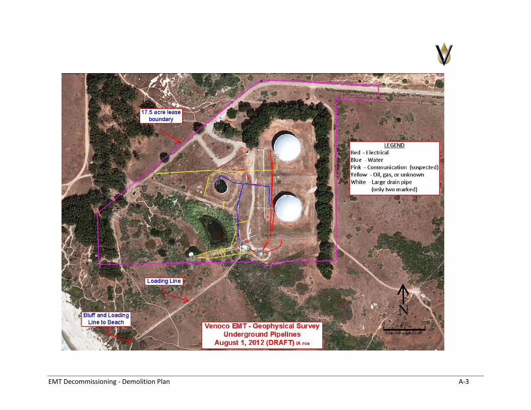
EMT Decommissioning - Demolition Plan A-3
