production technology (me-310) index
TRANSCRIPT
CHAROTAR UNIVERSITY OF SCIENCE & TECHNOLOGY FACULTY OF TECHNOLOGY & ENGINEERING CHAMOS Matrusanstha Department of Mechanical Engineering
PRODUCTION TECHNOLOGY (ME-310)
INDEX
Sr.
No.
Performance
Date Title No.
of Pages
Marks
Assessment
Date Sign
1
STUDY OF TOOL GEOMETRY
2
EXPERIMENT TO FIND SHEAR
ANGLE
3
CHIP THICKNESS ANALYSIS
4
PROBLEMS ON MERCHANT
CIRCLE DIAGRAM
5
EFFECT OF PEAK CURRENT
ON MRR IN EDM
6
STUDY OF ULTRASONIC
MACHINING
7
STUDY OF SINGLE SPINDLE
AUTOMATS
8
STUDY OF JIGS AND FIXTURES
9
STUDY OF DESIGN OF
MACHINE TOOL ELEMENTS
10
A CASE STUDY ON “FAST
PRODUCTION OF GEAR
PROTOTYPES”
1

ME – 310 PRODUCTION TECHNOLOGY
CO1 Understand the theory behind cutting of materials for shaping them into desired forms.
CO2 Analyze forces involved during machining process.
CO3 Understand motions in machine tools and analyze various elements of machine tools.
CO4 Outline tooling equipments of semi-automats and automats.
CO5 Interpret modern machining processes for material removal application.
CO6 Understand gear and thread manufacturing methods.
CO7 Understand work holding method for production activities.
List of Experiment ( ME310-PRODUCTION TECHNOLOGY)
Sr. No. Title Course Outcomes
1 Study of Tool Geometry CO1
2 Experiment to Find Shear Angle CO1,CO2
3 Chip Thickness Analysis CO1, CO2
4 Problems on Merchant Circle Diagram CO2
5 Effect of Peak Current on MRR in EDM CO5
6 Study of Ultrasonic Machining CO5
7 Study of Single Spindle Automats CO4
8 Study of Jigs And Fixtures CO7
9 Study of Design of Machine Tool Elements CO3, CO6
10 A case study on “Fast production of gear prototypes” CO5, CO6
List of Assignment(ME310-PRODUCTION TECHNOLOGY)
Sr.
No.
Title Course
Outcomes 1 Assignment 1- Theory of Metal Cutting CO1, CO2
2 Assignment 2- Analysis of Machine Tools CO3
3 Assignment 3- Semi Automats and Automats CO4
4 Assignment-4- Modern Machining Processes CO5
5 Assignment-5- Gear and Thread Manufacturing, Jigs and Fixtures CO6, CO7
CHAROTAR UNIVERSITY OF SCIENCE & TECHNOLOGY FACULTY OF TECHNOLOGY & ENGINEERING CHAMOS Matrusanstha Department of Mechanical Engineering
Production Technology (ME-310) Date:
EXPERIMENT No. 1
STUDY OF TOOL GEOMETRY
AIM:
STUDY OF TOOL GEOMETRY OF SINGLE POINT, MULTI POINT CUTTING
TOOL. SHARPENING OF SINGLE POINT CUTTING TOOL.
THEORY:
INTRODUCTION:
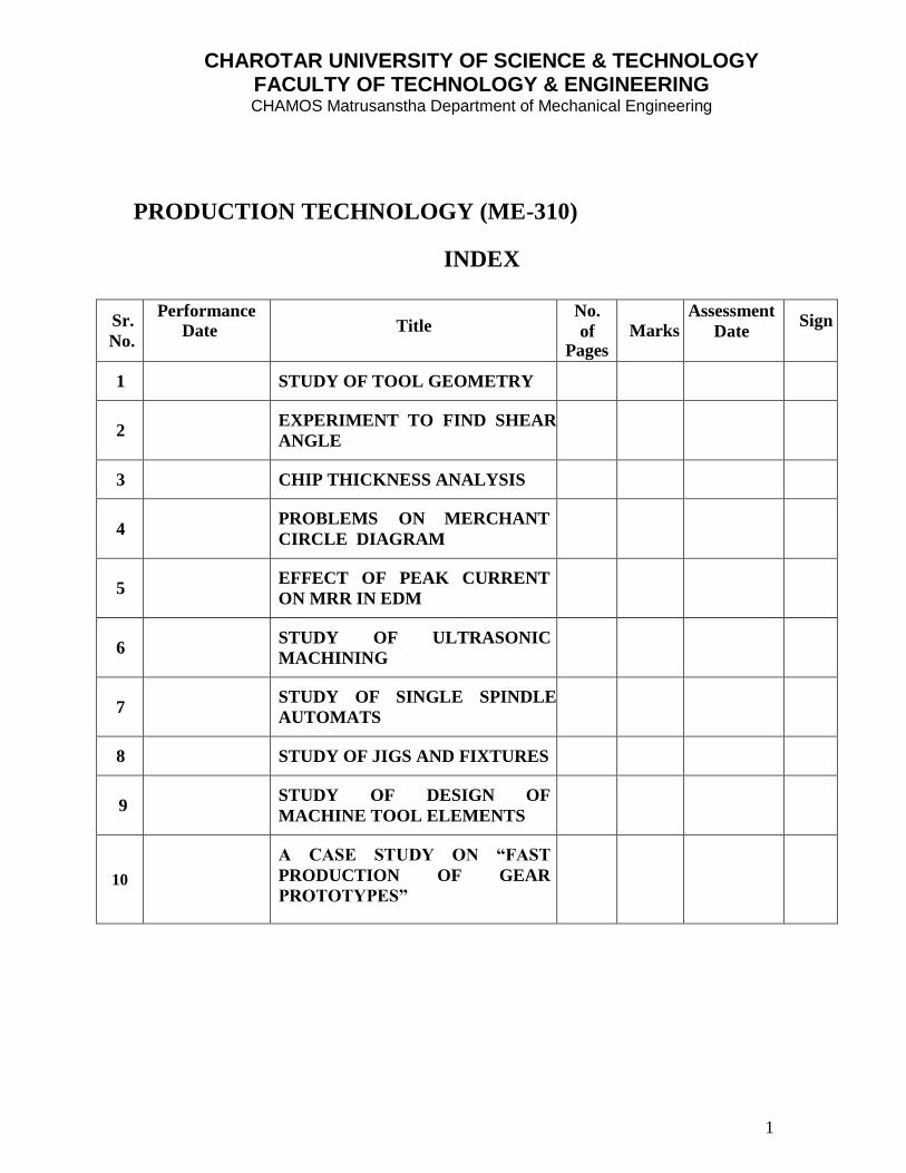
It is an instrumental media which helps to remove material from the work piece, and to
give desired shape and size with the help of single point contact tool or multi point
cutting tool. The relative motion is established between work and the cutting tool to
undergo cutting process.
CUTTING TOOL CLASSIFICATION:
According to different methods
According to method of manufacturing-
Forged tool, Tipped tool brazed to the carbon steel shank,
Tipped tool fastened mechanically to the carbon steel shank.
According to the method of holding the tool- Solid tool, Tool bit inserted in the tool holder.
According to the method of using the tool- Turning, Chamfering, Thread cutting,
Facing, Grooving, Forming, Boring, Internal thread cutting, Parting off.
According to the method of applying the feed- Right hand, Left hand, Round nose.
Figure 1: Single and Multi-point Cutting Tools.
2
CHAROTAR UNIVERSITY OF SCIENCE & TECHNOLOGY FACULTY OF TECHNOLOGY & ENGINEERING CHAMOS Matrusanstha Department of Mechanical Engineering
3
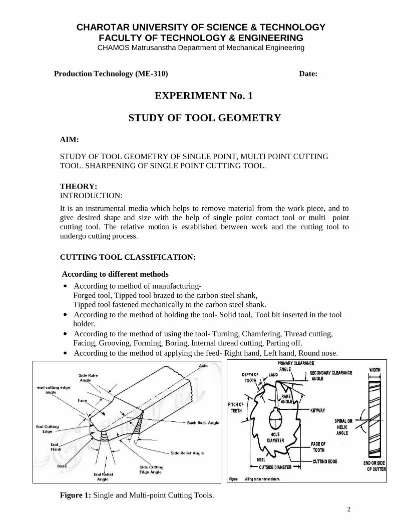
Figure 2: Shapes of Single Point Cutting Tools
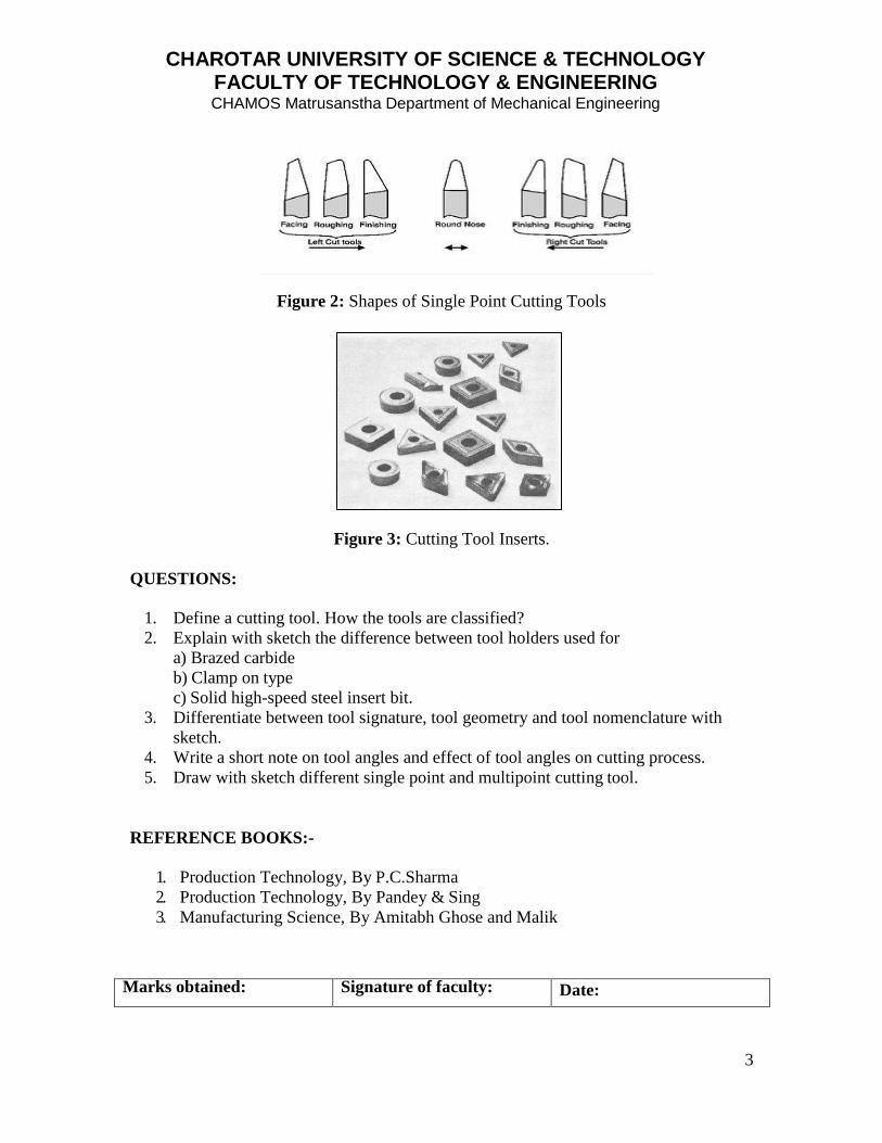
Figure 3: Cutting Tool Inserts.
QUESTIONS:
1. Define a cutting tool. How the tools are classified?
2. Explain with sketch the difference between tool holders used for
a) Brazed carbide
b) Clamp on type
c) Solid high-speed steel insert bit.
3. Differentiate between tool signature, tool geometry and tool nomenclature with
sketch.
4. Write a short note on tool angles and effect of tool angles on cutting process.
5. Draw with sketch different single point and multipoint cutting tool.
REFERENCE BOOKS:-
1. Production Technology, By P.C.Sharma
2. Production Technology, By Pandey & Sing
3. Manufacturing Science, By Amitabh Ghose and Malik
Marks obtained: Signature of faculty: Date:
CHAROTAR UNIVERSITY OF SCIENCE & TECHNOLOGY FACULTY OF TECHNOLOGY & ENGINEERING CHAMOS Matrusanstha Department of Mechanical Engineering
4
Production Technology (ME-310) Date:
EXPERIMENT No. 2
EXPERIMENT TO FIND SHEAR ANGLE
AIM:
TO EVALUATE SHEAR ANGLE AS A FUNCTION OF THE RAKE ANGLE OF THE
TOOL.
THEORY:
INTRODUCTION:
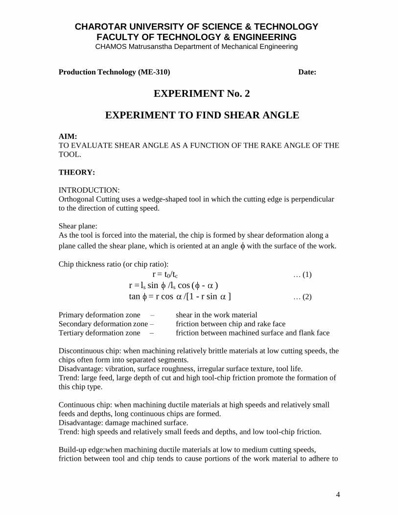
Orthogonal Cutting uses a wedge-shaped tool in which the cutting edge is perpendicular
to the direction of cutting speed.
Shear plane:
As the tool is forced into the material, the chip is formed by shear deformation along a
plane called the shear plane, which is oriented at an angle with the surface of the work.
Chip thickness ratio (or chip ratio):
r = t0/tc … (1)
r = ls sin /ls cos ( - )
tan = r cos /[1 - r sin ] … (2)
Primary deformation zone – shear in the work material
Secondary deformation zone – friction between chip and rake face
Tertiary deformation zone – friction between machined surface and flank face
Discontinuous chip: when machining relatively brittle materials at low cutting speeds, the
chips often form into separated segments.
Disadvantage: vibration, surface roughness, irregular surface texture, tool life.
Trend: large feed, large depth of cut and high tool-chip friction promote the formation of
this chip type.
Continuous chip: when machining ductile materials at high speeds and relatively small
feeds and depths, long continuous chips are formed.
Disadvantage: damage machined surface.
Trend: high speeds and relatively small feeds and depths, and low tool-chip friction.
Build-up edge:when machining ductile materials at low to medium cutting speeds,
friction between tool and chip tends to cause portions of the work material to adhere to
CHAROTAR UNIVERSITY OF SCIENCE & TECHNOLOGY FACULTY OF TECHNOLOGY & ENGINEERING CHAMOS Matrusanstha Department of Mechanical Engineering
5
the rake face of the tool near the cutting edge. This formation is called a build-up edge
(BUE).
Characteristic: cyclical in nature, it forms, grows, and breaks off. Unstable.
Disadvantage: change tool geometry, cutting forces, cutting temperature and machined
surface quality.
The Merchant equation defines the general relationship between rake angle, tool-chip
friction, and shear plane angle as under:-
= 45 + /2 - /2
Where =Shear angle; Rake angle; =Friction Angle
OBSERVATIONS:
Tool Angles:
Tool Material:
Workpiece Material:
Spindle Speed (rpm):
Depth of Cut:
OBSERVATION TABLE:
Test Side Rake Angle,
(Degrees)
Feed t1, (mm)
Chip Thickness t2 (mm)
Theoretical Shear
Angle,
(Degrees)
1 -5
2 0
3 +5
4 +10
5 +15
6 +20
7 +25
CONCLUSION:
Marks obtained: Signature of faculty: Date:
CHAROTAR UNIVERSITY OF SCIENCE & TECHNOLOGY FACULTY OF TECHNOLOGY & ENGINEERING CHAMOS Matrusanstha Department of Mechanical Engineering
6
Production Technology (ME-310) Date:
PRACTICAL NO. 3
CHIP THICKNESS ANALYSIS AIM:
TO STUDY EFFECT OF CUTTING PARAMETERS ON CHIP THICKNESS
APPARATUS/INSTRUMENTS: Lathe with a three-jaw chuck, Vernier Caliper, Ø20;
20 mm long M.S. rod.
PROCEDURE: Set up the lathe and machine the MS rod for different set of cutting
parameters. The cutting parameters are speed, feed and depth of cut. In the first set up
vary the depth of cut, keeping the speed and feed constant. In the second set up vary the
speed, keeping the feed and depth of cut constant. In the third setup, vary the feed,
keeping the speed and depth of cut constant. Collect the chips and measure the thickness
at four different points along the length.
OBSERVATIONS:
1. Material: MS, Ø20 and 20 mm long 2. Parameters: Speed
TABLE A: Speed = 250rpm; Feed = 0.12mm/rev
Depth of cut
(mm)
Chip Thickness (mm)
T1 T2 T3 T4 Average
0.5
1.0
1.5
TABLE B: Feed = 0.12mm/rev; Depth of cut = 0.5 mm
Speed (rpm)
Chip Thickness (mm)
T1 T2 T3 T4 Average
0.06
0.12
0.24
CHAROTAR UNIVERSITY OF SCIENCE & TECHNOLOGY FACULTY OF TECHNOLOGY & ENGINEERING CHAMOS Matrusanstha Department of Mechanical Engineering
7
TABLE C: Speed = 350 rpm; Depth of cut = 1 mm
Feed (mm/rev)
Chip Thickness (mm)
T1 T2 T3 T4 Average
0.06
0.12
0.24
GRAPHS:
TABLE A: Depth of cut Vs Chip Thickness
TABLE B: Speed Vs Chip Thickness
TABLE C: Feed Vs Chip Thickness
CONCLUSION:
REFERENCE BOOKS:-
1. Production Technology, By P.C.Sharma
2. Production Technology, By Pandey & Sing
3. Production Technology, By HMT
Marks obtained: Signature of faculty: Date:
CHAROTAR UNIVERSITY OF SCIENCE & TECHNOLOGY FACULTY OF TECHNOLOGY & ENGINEERING CHAMOS Matrusanstha Department of Mechanical Engineering
8
Production Technology (ME-310) Date:
EXPERIMENT No. 4
PROBLEMS ON MERCHANT CIRCLE DIAGRAM
Problem 1
During turning a ductile alloy by a tool of γ0 =10 0, it is found PZ=1000N,
P=400N,PY=300N and ζ=2.5.Evaluate using MCD, the values of F,N and µ as well as PS
and Pn for the above machining.
Problem 2
During turning a steel rod of diameter 160mm at speed 560rpm, feed 0.32mm/rev and
depth of cut 4.0mm by a ceramic insert of geometry
00,-100, 60,60,150,750,0(mm) The following was observed:
PZ=1600N, PX=800N and chip thickness=1mm. Determine with the help of MCD the
possible values of F,N,Ma, PS and Pn cutting power and specific energy consumption.
Problem 3
For turning a given steel rod by a tool of given geometry if shear force PS, Frictional
force F and shear angle γ0 could be estimated to be 400N and 300N resp. then what
would be the possible values of Px, PY And PZ? Use MCD.
REFERENCE BOOKS:-
1. Production Technology, By P.C.Sharma
2. Production Technology, By Pandey & Sing
3. Tool Design, By Donaldson
Marks obtained: Signature of faculty: Date:
CHAROTAR UNIVERSITY OF SCIENCE & TECHNOLOGY FACULTY OF TECHNOLOGY & ENGINEERING CHAMOS Matrusanstha Department of Mechanical Engineering
9
Production Technology (ME-310) Date:
EXPERIMENT No. 5
EFFECT OF PEAK CURRENT ON MRR IN EDM
AIM: TO STUDY THE EFFECT OF PEAK CURRENT IP ON MRR IN ELECTRICAL
DISCHARGE MACHINING.
THEORY:
Material Removal rate is a function of current, voltage, pulse ON time, pulse OFF time,
polarity, etc. Here the more important parameter is the current. Keeping all other
parameter as constant the effect of current on material removal rate has to be studied.
RELEVANCE:
It is to get an idea about how peak current and material removal rate are related under
constant environment. The experiment helps us to select a proper current for a particular
material removal rate when called for.
APPRATUS:
EDM machine with specifications given in table. (Student will write the specification in
tabular format.)
PROCEDURE:
Standard procedure has to be followed for initial setting of the machine. Change the peak
current Keeping all other parameters constant and observe the material removal rate.
Note down all the condition.
OBSERVATION TABLE:
Sr.
No.
Peak
current, Ip
Weight of the w/p MRR
in
gm/sec
Time ‘t’ in sec.
Before After Difference Start Stop
1
2
3
4
CHAROTAR UNIVERSITY OF SCIENCE & TECHNOLOGY FACULTY OF TECHNOLOGY & ENGINEERING CHAMOS Matrusanstha Department of Mechanical Engineering
10
PROCEDURE:
I. Initial weight of the work piece (W1) = gm. II. Final weight of the work piece (W2) = gm.
III. Material Removal Rate: (W1 - W1) / t = gm/sec.
CONCLUSION:
Comment on the utility of the experiment. Insert the Graph.
REFERENCE BOOKS:-
1. Production Technology, By P.C.Sharma
2. Technology of Machine Tools, By Krar, Check
3. Materials & Processes in Manufacturing, By Black, Kohser
4. Production Technology, By HMT
Marks obtained: Signature of faculty: Date:
CHAROTAR UNIVERSITY OF SCIENCE & TECHNOLOGY FACULTY OF TECHNOLOGY & ENGINEERING CHAMOS Matrusanstha Department of Mechanical Engineering
11
Production Technology (ME-310) Date:
EXPERIMENT No. 6
ULTRASONIC MACHINING AIM:
STUDY OF ULTRASONIC MACHINING OF ABRASIVE MATERIAL.
THEORY:
INTRODUCTION:
This is designed to highlight aspects of the ultrasonic machining process for the
machining of non-ferrous metals, glass, ceramics and other hard, brittle materials.
DEFINITION:
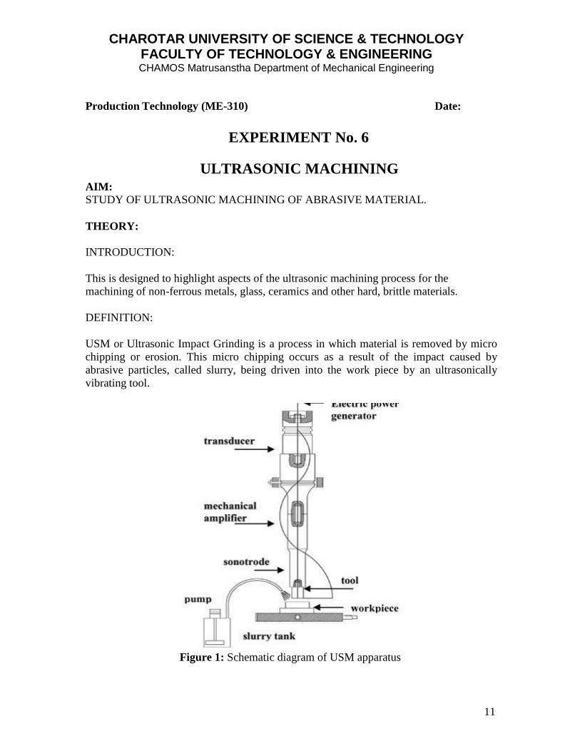
USM or Ultrasonic Impact Grinding is a process in which material is removed by micro
chipping or erosion. This micro chipping occurs as a result of the impact caused by
abrasive particles, called slurry, being driven into the work piece by an ultrasonically
vibrating tool.
Figure 1: Schematic diagram of USM apparatus
CHAROTAR UNIVERSITY OF SCIENCE & TECHNOLOGY FACULTY OF TECHNOLOGY & ENGINEERING CHAMOS Matrusanstha Department of Mechanical Engineering
12
USM Main Components:
Pneumatic Press: A very rigid and low friction precision feed system.
Ultrasonic Generator: Designed as Amplitude regulated power system and
equipped with an automatic frequency control.
Machining Head: Comprising of Sound Transducer, acoustic transformer and
sonotrode (Electrode or Cutting tool).
Process Control Unit: Microprocessor Controlled.
Automatic safety Device for overload or overheating.
Chilling system & slurry system.
PROCESS:
1. The goal of USM is higher machining rates with better surface quality at the
lowest cost possible.
2. The stresses developed in the subsurface are of critical importance when
machining brittle ceramics as the inherent micro structural variations and
subsurface flaw characteristics influence the resultant stress distributions in the
subsurface.
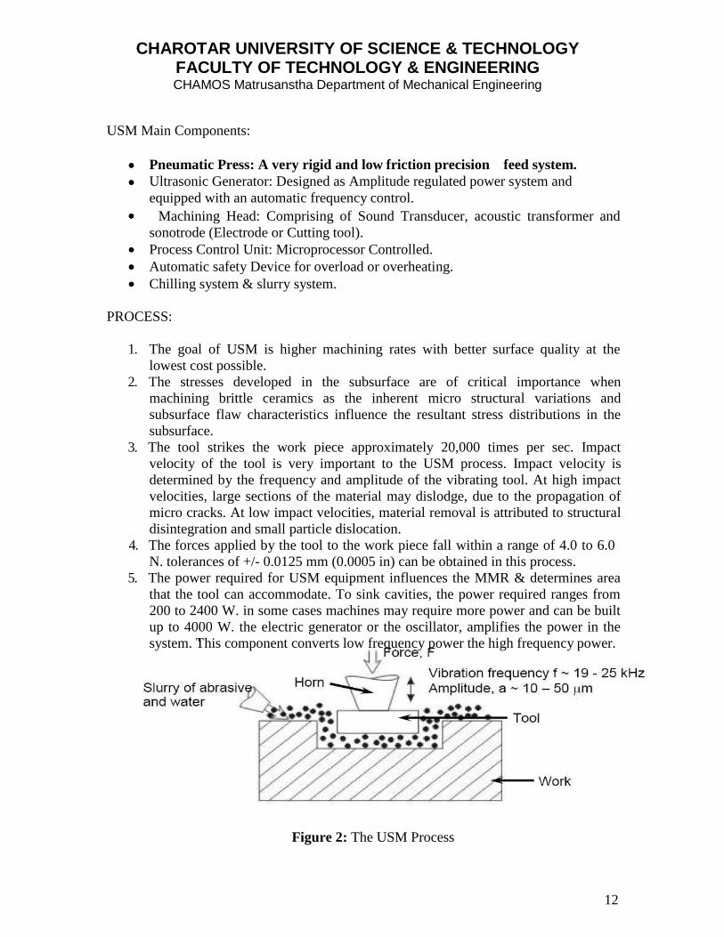
3. The tool strikes the work piece approximately 20,000 times per sec. Impact
velocity of the tool is very important to the USM process. Impact velocity is
determined by the frequency and amplitude of the vibrating tool. At high impact
velocities, large sections of the material may dislodge, due to the propagation of
micro cracks. At low impact velocities, material removal is attributed to structural
disintegration and small particle dislocation.
4. The forces applied by the tool to the work piece fall within a range of 4.0 to 6.0
N. tolerances of +/- 0.0125 mm (0.0005 in) can be obtained in this process.
5. The power required for USM equipment influences the MMR & determines area
that the tool can accommodate. To sink cavities, the power required ranges from
200 to 2400 W. in some cases machines may require more power and can be built
up to 4000 W. the electric generator or the oscillator, amplifies the power in the
system. This component converts low frequency power the high frequency power.
Figure 2: The USM Process
CHAROTAR UNIVERSITY OF SCIENCE & TECHNOLOGY FACULTY OF TECHNOLOGY & ENGINEERING CHAMOS Matrusanstha Department of Mechanical Engineering
13
ABRASIVE:
The abrasive particles are usually boron carbide ranging in size from 100 to 1000, with
1000 designed for machining. The grains are suspended in liquid slurry carries away
debris from the cutting area. The slurry has a water concentration that ranges from20 %
to 60% by volume. Grains are usually boron carbide, but aluminum oxide and silicon
carbide are often used.
The other types of abrasives are Diamond, Cubic Boron Nitride, Boron carbide, and
Aluminum Oxide.
The most common abrasive used in the ultrasonic machining process is Boron Carbide,
which is used when machining metals, high-density ceramics, minerals and semi-precious
and precious stones. When machining low-density ceramics, glass, silicon, germanium
and mineral stones silicon carbide is most often used.
TOOL MATERIAL AND ITS CONFIGURATION:
The most common tool material is M.S. in some cases; other tool materials such as SS
303, Monel, 52100 Steel, Aluminum and Molybdenum are used to make the tool. The
mass of the tool used in ultrasonic machining is important due to process constraints. A
tool with a large mass will absorb ultrasonic energy and reduce machining efficiency.
The tool is configured in the exact shape to be ground into the work piece. The tip of the
tool vibrates at low amplitude and a high frequency. This vibration forces the cutting
action of the abrasive particles. In USM process, the tool, made of softer material than
that of the work piece, is oscillated by the booster and sonotrode at a frequency about 20
KHz. With an amplitude of about 25.4 um (0.001 in). It forces the abrasive grits, in the
gap between the tool and the work piece, to impact normally and successively on the
work surface, thereby machining the work surface.
ADVANTAGES OF USM:
1. USM solves the problem of slow, expensive, ineffective machining of ceramics.
2. High MMR with low cutting pressures.
3. Little surface damage and only small reductions in strength.
4. Position accuracy is generally within 0.003 inches.
5. Repeatability of the process is 0.001 in.
DISADVANTAGES OF USM:
1. Tool wears or taper in the cut may reduce the effectiveness of the process.
2. The slurry has to be fed into and removed from the gap between the tool and the
work piece, thus limiting the MRR.
3. The presence of slurry limits the accuracy, especially small crevices.
4. It is difficult to monitor directly the presence of progress in the process.
CHAROTAR UNIVERSITY OF SCIENCE & TECHNOLOGY FACULTY OF TECHNOLOGY & ENGINEERING CHAMOS Matrusanstha Department of Mechanical Engineering
14
5. If the impact velocity of the tool is too high, the propagated cracks can merge at
the surface and dislodge large sections of the material.
6. If the abrasive slurry becomes embedded in the material, work hardening occurs,
and as the process continues material is chipped away due to the contracted
brittleness.
IMPORTANT OUTCOMES:
The tougher the work piece materials, the more tool wear and the lower the machining
rates and precision of the holes. The more brittle the materials are, the greater the
tendency for metal removal by fracture. The tougher the material, the greater the
tendency for metal removal based on plasticity. The Angle is defined as the opening
between two lines, which meet at a point. The Vernier bevel protractor can read to the
accuracy of 5’. Sine bar is used for the accurate angle measurement and to locate the
work to a given angle. Sine bar is reliable for angle less than and it becomes in
accurate as the angle increases. It is impractical to use sine bar for angle above 45 Angle
gauges are used to measure the angle to the accuracy of 3”.
QUESTIONS:
1. Explain mechanics of ultrasonic machining.
2. Write down important process parameters of USM process. Which parameters
affect material removal rate (MRR) in USM.
3. Explain principle-non-traditional machining process. What is the function of horn
in it?
4. Explain the principal of USM process with a neat sketch. State the requirements
of abrasives in this process.
5. Write at least five practical applications of USM process and brief each
application within five lines.
6. Write the detailed specification of the USM machine in your lab.
REFERENCE BOOKS:-
1. Production Technology, By P.C.Sharma
2. Production Technology, By O.P.Khanna
3. Workshop Technology, By S.K.Hajara Chaudhary Part:II
4. Production Engineering & Science, ByPandey & Singh
5. Production Technology, By HMT
Marks obtained: Signature of faculty: Date:
CHAROTAR UNIVERSITY OF SCIENCE & TECHNOLOGY FACULTY OF TECHNOLOGY & ENGINEERING CHAMOS Matrusanstha Department of Mechanical Engineering
15
Production Technology (ME-310) Date:
EXPERIMENT No. 7
SINGLE SPINDLE AUTOMATS
AIM:
MANUFACTURING A COMPONENT ON SINGLE SPINDLE AUTOMATES AS
PER DRAWING.
THEORY:
INTRODUCTION:
The Capstan (C) & Turret (T) lathes are developed for the purpose of producing mass
identical parts with more production rates and at the same time very less rejection rates.
MAIN PARTS:
Bed, All geared headstock, Saddle, Multi station tool post. Here, tailstock is replaced by
hexagonal turret sliding on the machine bed. Six faces of turret holds six different
operation tools, either with auto indexing or manual indexing. By indexing the operator
brings tool in the axis of lathe, keeping in view the sequence of operations. The job is
clamped either in chucks or collets and all feed movements are regulated with the help of
adjustable stops, for specific operations.
WORKING PRINCIPLE OF SEMI AUTOMATS AND FULL AUTOMATS:
CONSTRUCTION DETAILS—EVALUATION PROCESS OF WORKING:
1. For properly setting up a turret, skill is necessary in the selection, mounting, and
adjustment of the tools.
2. In small lot production, it is important that this work can be done quickly, so as
not to consume too much of the total production time, which consists of set up,
work piece handling, machine handling and cutting time.
3. Set up time is reduced by having the tool in up to date condition and readily
available.
4. For short run jobs, a permanent set up of the usual bar tools on the turret is a
means of reducing time.
5. The tools selected are standard and when permanently mounted, they may be
quickly adjusted for various jobs.
6. The loading and unloading time, which is the time consumed in mounting or
removing the work, depends largely on the work holding devices used.
7. For bar work, this time is reduced to a minimum by using bar stock collets.
8. The time it takes, to pre position the tools ready for cutting is part of the cycle
time.

CHAROTAR UNIVERSITY OF SCIENCE & TECHNOLOGY FACULTY OF TECHNOLOGY & ENGINEERING CHAMOS Matrusanstha Department of Mechanical Engineering
16
9. This is reduced by having the tool in proper sequence for convenient use and by
taking
10. Multiple or combined cuts when ever possible.
11. The balance of the machine handling time is made up of the time necessary to
change the speeds and feeds.
12. Cutting time is controlled with proper cutting tools, feeds and speeds.
13. Combined cuts refer to the simultaneous use of both slide and turret tools.
14. In bar work, combined cuts are especially desirable, as an additional support is
given, to the work piece, there by reducing spring and chatter.
15. In chucking work, internal operations such as drilling or boring may frequently be
combined with turning or facing cuts from the square turret.
16. Time is also saved, by taking multiple cuts, that is, having two or more tools
mounted on one tool station.
17. For out side turning, a single cutter turner or box tool has been developed As bar
stock is supported only at the collets, additional support must be provided for
heavy cuts to be taken.
18. This is done by means of two rollers that contact the turned diameter of the stock
to counter the thrust of the cutting tool.
MAJOR OPERATIONS TO BE CARRIED OUT USING AUTOMATES:
Turning, Drilling, Boring, Threading, Reaming, Necking, Chamfering and cutting off or
parting off. Other specialized operations are possible with specialized tools.
QUESTIONS:
1. What are the main parts of capstan and turret lathes? Where they differ?
2. Explain step-by-step procedure of part you already made using Capstan & Turret
lathe in your workshop.
3. Write down different types of turret lathes and their applications.
4. Compare engine lathe with automats.
5. Compare and differentiate between capstan and turret lathe.
6. Explain with sketch the function of bar feeding mechanism.
7. Explain indexing mechanism of single spindle automate in your workshop.
8. Write the detailed specification of single spindle automate in your workshop.
REFERENCE BOOKS:-
1. Production Technology, By P.C.Sharma
2. Workshop Technology, By S.K.Hajara Chaudhary Part:II
3. Production Engineering & Science, ByPandey & Singh
4. Production Technology, By HMT
Marks obtained: Signature of faculty: Date:
CHAROTAR UNIVERSITY OF SCIENCE & TECHNOLOGY FACULTY OF TECHNOLOGY & ENGINEERING CHAMOS Matrusanstha Department of Mechanical Engineering
17
hold and job.
Production Technology (ME-310) Date:
EXPERIMENT No. 8
JIGS AND FIXTURES AIM:
TO STUDY DIFFERENT JIGS AND FIXTURES AVAILABLE IN WORKSHOP.
THEORY:
INTRODUCTION:
Work piece control is biggest issue for a process planner. Because loss of work piece
control will result in work pieces having out of dimension condition. Once the drawing
for a part is completed it is sent to process planning department where method and
sequence of manufacture are finalized. This department also floats the requirements for
different tooling needed for the completion of job. Jigs and fixtures are tooling needed for
the satisfactory work piece control, in simple terms work holding devices.
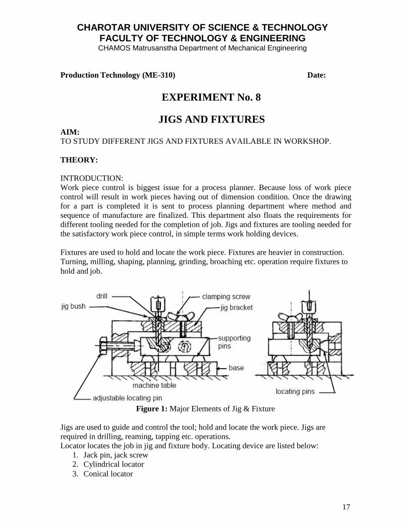
Fixtures are used to hold and locate the work piece. Fixtures are heavier in construction.
Turning, milling, shaping, planning, grinding, broaching etc. operation require fixtures to
Figure 1: Major Elements of Jig & Fixture
Jigs are used to guide and control the tool; hold and locate the work piece. Jigs are
required in drilling, reaming, tapping etc. operations.
Locator locates the job in jig and fixture body. Locating device are listed below:
1. Jack pin, jack screw
2. Cylindrical locator
3. Conical locator

CHAROTAR UNIVERSITY OF SCIENCE & TECHNOLOGY FACULTY OF TECHNOLOGY & ENGINEERING CHAMOS Matrusanstha Department of Mechanical Engineering
18
4. Diamond locator
5. Vee locator
Clamps in jigs and fixtures are used to provide holding force to the work piece.
Clamps are of different types:
1. Strap clamp
2. Screw clamp
3. Hinged clamp
4. Wedge clamp.
5. C- clamp
6. Toggle clamp
7. Cam operated clamp
Bushes in jig dose the function of guiding the tool.
1. Fixed bush
2. Liner bush
3. Renewable bush
4. Slip bush.
5. Screw bush
6. Special bush
Different types of jigs are:
1. Template jig
2. Plate jig
3. Channel jig
4. Leaf jig
5. Universal jig
6. Index jig
7. Turn over jig etc.
Fixtures are mainly classified on base of method of manufacturer.
1. Milling fixture
2. Turning fixture
3. Grinding fixture
4. Boring fixture
5. Broaching fixture
6. Welding fixture
7. Assembly fixture
OBSERVATION:
Analyze each and every jig and fixture in our workshop in context of function location
and clamping facility.

CHAROTAR UNIVERSITY OF SCIENCE & TECHNOLOGY FACULTY OF TECHNOLOGY & ENGINEERING CHAMOS Matrusanstha Department of Mechanical Engineering
19
QUESTIONS:
1. Explain the principle of 3-2-1 locations.
2. Differentiate between jigs and fixtures.
3. List out different types of clamps & Bushes.
4. Explain various types of jigs.
5. What considerations are taken while designing a clamp?
6. Discuss Design consideration for fixture.
7. Explain the Principle of working of Indexing Drill Jig with sketch
REFERENCE BOOKS:-
1. Production Technology, By P.C.Sharma
2. Production Technology, By R.K.Jain
3. Tool Design, By Donaldson
Marks obtained: Signature of faculty: Date:
CHAROTAR UNIVERSITY OF SCIENCE & TECHNOLOGY FACULTY OF TECHNOLOGY & ENGINEERING CHAMOS Matrusanstha Department of Mechanical Engineering
20
Production Technology (ME-310) Date:
EXPERIMENT No. 9
STUDY OF DESIGN OF MACHINE TOOL ELEMENTS
AIM:
TO STUDY DESIGN OF MACHINE TOOLS ELEMENTS.
THEORY:
INTRODUCTION:
Types of Machine Tools:
Lathes: In a turning or facing operation on a lathe, the workpiece rotates to provide the
cutting motion, and the feed is by motion of the cutting tool. Lathes are used for the
production of all kinds of components which are symmetrical about their axis of rotation.
Drilling Machines: The cutting action results from the rotary movement of the cutting
tool or workpiece, with a feed motion of the workpiece or tool, in the direction of the
rotating axis. Drilling machines are used for drilling, boring, counter-sinking, reaming
and tapping operations.
Milling Machines: Similar to drilling. In the case of milling, both the tool and the
workpiece can move horizontal or vertical direction. Milling machines are used to
produce flat surfaces, sink, and slot.
Machining Centers (Horizontal / Vertical)
Transfer Machines: A number of work stations (turning, drilling, milling, etc.) aranged
behind each other, linked by the means of an automatic work transportation unit, which
governs their positions and the timing cycle.
Grinding Machines: Basically, the cutting tool provides the cutting movement on
grinding machines. The contact between the workpiece and the grinding wheel is either
on the wheel periphery or on the wheel face.
Honing Machines: The fundamental difference between honing and grinding techniques,
is that when honing, the aim is only for an improvement in surface finish and dimensional
accuracy.
CHAROTAR UNIVERSITY OF SCIENCE & TECHNOLOGY FACULTY OF TECHNOLOGY & ENGINEERING CHAMOS Matrusanstha Department of Mechanical Engineering
21
Construction of Machine Tool
Frame: The frame is a machine's fundamental element. This casting or fabricated section
carries all the active and passive components- spindles, tables, and controls. Frames are
made from welded steel, cast iron, or composite concrete. When constructing the frame,
loads, damping, apertures, heat transfer, and noise are major design considerations.
Slides and Rails: Guide ways are frame elements that carry the workpiece table or
spindles. There are two way types: box ways and roller ways.
Box way: This oldest and simplest of the two. It has high stiffness, good damping
characteristics, a large surface contact area, and resistance to high cutting and shock load.
The rail for this design is cast or welded onto the frame or bolted in place. Cast ways are
difficult to repair and virtually impossible to replace.
Roller ways: This way type consists of a rail and a slide, but has a rolling-element
bearing between the two. Roller ways are lighter weight and operate with less friction, so
they can positioned faster and with less energy. Roller way, however, takes more space
and is usually more costly.
Spindles And Motors
Electric motor is the prime movers for most machine tool functions. They mostly use 3-
phase ac power supplied at 220 or 460 V. Today's spindles generally operate around
10,000 rpm or higher, range from 5-150 hp (3.7-112 kW).
Spindle motors: A spindle is a motor-driven shaft that both positions and transmits power
to a tool or holds a workpiece. Spindle motors are the major motors on a machine tool,
drive the spindle shafts.
Feed motors: Positioning motors drive the ballscrews that move the sildes carrying
spindles or worktables. Today's most popular positioning motor is technically called a dc
brushless motor, more commonly known as an ac servo motor.
Linear motors: A linear motor is essentially a "straightened out" rotary motor. The rotor
is the slide and the stator is a row of windings. It is very lightweight relative to the
conventional motor, but less accurate in positioning.
QUESTIONS:
1. Machine tool structures are made rigid for high process capability. Justify your
answer.
2. What are guide-ways? Explain its types.
3. Discuss various speed drives in machine tools.
CHAROTAR UNIVERSITY OF SCIENCE & TECHNOLOGY FACULTY OF TECHNOLOGY & ENGINEERING CHAMOS Matrusanstha Department of Mechanical Engineering
22
REFERENCE BOOKS:-
1. Production Technology, By R.K.Jain
2. Machine Tool Design & Numerical control, By N.K.Mehta
3. A TextBook on Production Technology By P.C.Sharma
Marks obtained: Signature of faculty: Date:
CHAROTAR UNIVERSITY OF SCIENCE & TECHNOLOGY FACULTY OF TECHNOLOGY & ENGINEERING CHAMOS Matrusanstha Department of Mechanical Engineering
23
Production Technology (ME-310) Date:
EXPERIMENT No. 10
A CASE STUDY ON “FAST PRODUCTION OF GEAR
PROTOTYPES
AIM:
TO COMPARE THE TECHNOLOGIES FOR FAST PRODUCTION OF GEARS
NOTE:
Refer the attached research paper and answer the following questions.
QUESTIONS:
1. As per your opinion what is the need of faster production of gears in current time?
2. From present research paper enlist various methods for fast production of gears.
3. Write down general observations for each process for gear manufacturing in present paper.
4. Compare the various results obtained from all processes applied for gear manufacturing in present paper.
5. What differences you have observed between conventional and non-conventional gear manufacturing technologies?
Marks obtained: Signature of faculty: Date:
Procedia CIRP 14 ( 2014 ) 77 – 82
Available online at www.sciencedirect.com
2212-8271 © 2014 Published by Elsevier B.V. Open access under CC BY-NC-ND license. Selection and peer-review under responsibility of the International Scientific Committee of the 6th CIRP International Conference on High Performance Cuttingdoi: 10.1016/j.procir.2014.03.066
ScienceDirect
6th CIRP International Conference on High Performance Cutting, HPC2014
Fast production of gear prototypes - a comparison of technologies Jan Bouqueta
, Lars Hensgenb, Andreas Klinkb, Tom Jacobsc
, Fritz Klockeb, Bert Lauwersa
aDepartment of Mechanical Engineering, KU Leuven, Celestijnenlaan 300A, 3001 Leuven, Belgium
bWZL, RWTH Aachen University, Steinbachstr. 19, 52074 Aachen, Germany c Sirris, Wetenschapspark 9, 3590 Diepenbeek, Belgium
* Corresponding author. Tel.: +32 16 322856; E-mail address: [email protected]
Abstract
The time-to-market for automotive and other gear-involved products is still reducing. This demands new production technologies for the manufacturing of functional gear prototypes. At the moment gear prototypes are made using classical series production technologies, such as gear hobbing and grinding. However, these technologies require design specific dedicated tools, making the production of a functional gear prototype expensive and time-consuming. This paper presents an experimental investigation and comparison of different alternative production technologies for the manufacturing of functional gear prototypes. Wire-EDM, Selective Laser Melting and milling using standard milling tools, have been compared for the production of a spur gear out of 16MnCr5 steel. A strategy for the wire-cutting of a spur gear was developed, resulting in a total machining time of 22h – with very good gear quality in terms of geometrical accuracy and surface roughness. This same gear has been produced by SLM, with a total machining time of 17h. Two different milling strategies have been developed on a milling machine, resulting in a total machining time of 14h15min. The shape accuracy and surface roughness were compared using a CMM and a surface profiler. Taking these results into account and considering the fact that it is impossible to make helical gears or machine micro flank corrections using wire-EDM, it was concluded that the milling is the most promising production technology for functional gear prototypes. The fact that functional prototypes could be made without the current lead time (± 10 weeks) is a great improvement for the production of gear prototypes, meeting the shorter time-to-market requirements of today’s industry. © 2014 The Authors. Published by Elsevier B.V. Selection and peer-review under responsibility of the International Scientific Committee of the 6th CIRP International Conference on High Performance Cutting.
Gear manufacturing; Wire-EDM; SLM; milling; prototype
1. Introduction
The pressure on the automotive industry, as well as in other gear-using industries, is higher than ever. The time-to-market for new products is continuously reducing. The manufacturing of functional gear prototypes is identified as one of the bottlenecks. Functional gear prototypes, used for testing newgearboxes and differentials, are currently manufactured using classical production technologies. These technologies, such as gear hobbing, gear planning, shaping, skiving and grinding
[1], are only very efficient for large series production, gear hobbing and grinding require gear shape dependent tools, strongly increasing the cost for functional prototype gear manufacturing. In case the prototype will be accepted, the cost/part can of course be reduced since the tools can still be used, however not all designs (prototypes) will be continued to series production. Besides the cost, the time delay is even a bigger problem in gear prototyping, as the production of dedicated tools can take more than 9 weeks, a production technology capable of machining functional gear prototypes, without the need for dedicated tools, would strongly reduce the time-to-market for new gearboxes, differentials or any
© 2014 Published by Elsevier B.V. Open access under CC BY-NC-ND license. Selection and peer-review under responsibility of the International Scientific Committee of the 6th CIRP International Conference on High Performance Cutting
78 Jan Bouquet et al. / Procedia CIRP 14 ( 2014 ) 77 – 82
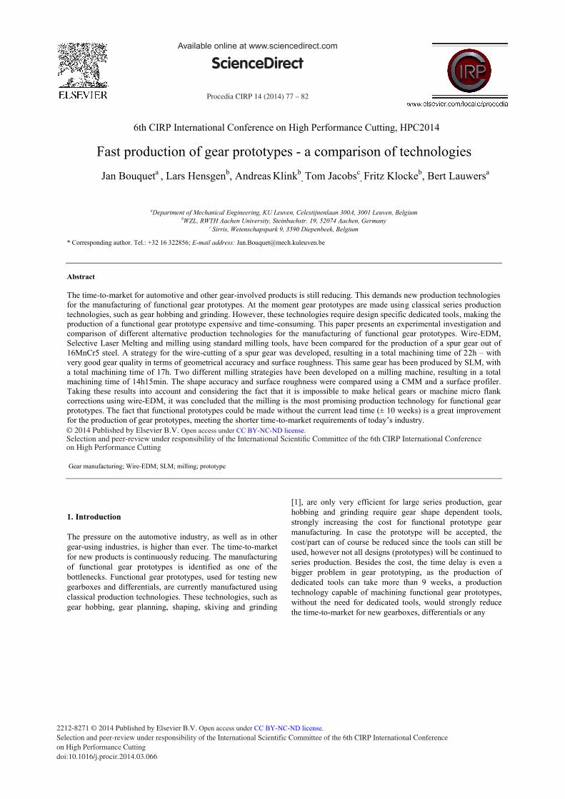
other application. The ability of fast prototyping gears makes it possible to make variants of a particular design for optimizing and tuning Noise, Vibration and Harshness (NVH) behavior. Today, gear prototypes are already produced by for example 3D printing technologies (using polymers), but this is only for demonstrating purposes. Functional gear prototypes should withstand the same loads and have the same NVH behavior as gears made by classical production technologies.
Commercial applications have been developed by a tool
manufacturer for shaping gears, using a special tool (gear design independent) on a turn-milling center (Figure 1(b)) [2]. Also in the field of CAD/CAM, commercial solutions are being developed for programming toolpaths for gear manufacturing using only standard ball- and endmills. So there is clear evolution towards more flexible production methods for gear prototypes [3,4,5,6]. Besides the above implementations, there are other potential technologies. In this paper three technologies, Wire EDM, Selective Laser Melting and milling, are compared for gear prototyping, in terms of productivity, accuracy and surface quality. Within this research, a demonstrator gear part has been proposed and the properties/characteristics are listed in Table 1. To perform tests on Wire EDM and milling, pre-turned forgings have been provided by the industrial partner, supporting this research. As turning can be done using standard tools, it makes sense to start from a pre-turned blank.
Table 1: Properties of the demonstrator gear part
Test case gear data
Material 16MnCr5
Number of teeth (Z) 36
Heigth 31.5 [mm]
Normal module (mn) 2.120 [mm]
Reference circle diameter (d0) 76.320 [mm]
Base circle diameter (db) 72.985 [mm]
Crowning width of tooth (cβ) 0.008 +/- 0.003 [mm]
Gear quality Acc. To DIN 3960
DIN Class 6
Surface finish (Ra) 0.8 [μm]
Profile angle variation fHα 6 [μm]
Profile form variation ff 8 [μm]
Total profile variation Ff 10 [μm]
Tooth trace angle variation fHβ 12 [μm]
Total tooth thrace variation Fβ 15 [μm]
Tooth trace form variation Fβf 9 [μm]
Run out Fr 24 [μm]
Cumulative pitch error Fp 32 [μm]
Single pitch error fp 7 [μm]
Pitch to pitch error fu 9 [μm]
2. Milling
2.1. Applied method
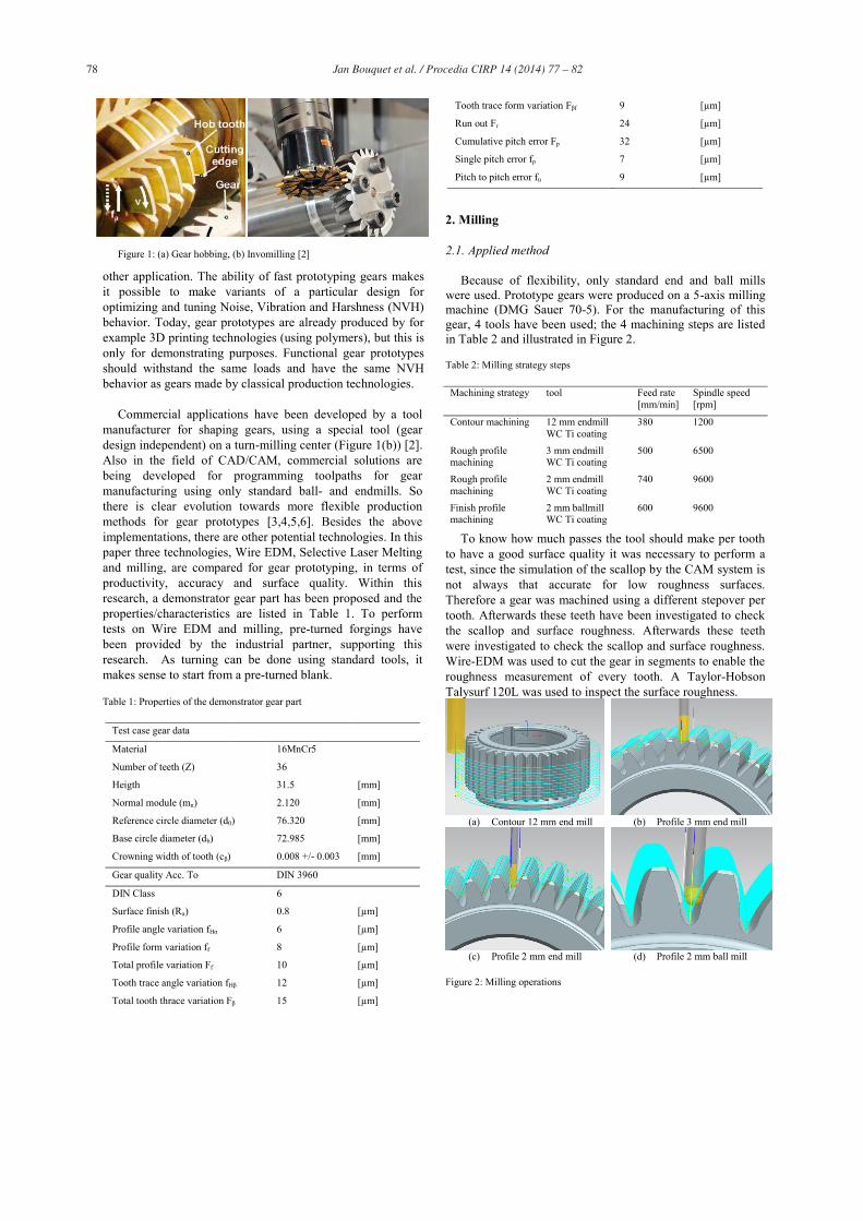
Because of flexibility, only standard end and ball mills were used. Prototype gears were produced on a 5-axis milling machine (DMG Sauer 70-5). For the manufacturing of this gear, 4 tools have been used; the 4 machining steps are listed in Table 2 and illustrated in Figure 2.
Table 2: Milling strategy steps
Machining strategy tool Feed rate [mm/min]
Spindle speed [rpm]
Contour machining 12 mm endmill WC Ti coating
380 1200
Rough profile machining
3 mm endmill WC Ti coating
500 6500
Rough profile machining
2 mm endmill WC Ti coating
740 9600
Finish profile machining
2 mm ballmill WC Ti coating
600 9600
To know how much passes the tool should make per tooth to have a good surface quality it was necessary to perform a test, since the simulation of the scallop by the CAM system is not always that accurate for low roughness surfaces. Therefore a gear was machined using a different stepover per tooth. Afterwards these teeth have been investigated to check the scallop and surface roughness. Afterwards these teeth were investigated to check the scallop and surface roughness. Wire-EDM was used to cut the gear in segments to enable the roughness measurement of every tooth. A Taylor-Hobson Talysurf 120L was used to inspect the surface roughness.
(a) Contour 12 mm end mill (b) Profile 3 mm end mill
(c) Profile 2 mm end mill (d) Profile 2 mm ball mill
Figure 2: Milling operations
Figure 1: (a) Gear hobbing, (b) Invomilling [2]
79 Jan Bouquet et al. / Procedia CIRP 14 ( 2014 ) 77 – 82
Table 3: Surface roughness in function of passes
No. of passes 150 250 400 450 500 550
Surface roughness Ra [μm]
0.76 0.38 0.27 0.21 0.24 0.22
Table 3 lists the Ra roughness values in function of machining passes per tooth. The surface roughness of around 0.3-0.2 μm Ra is well below the specified 0.8 μm Ra. For the final test gear, 450 passes per tooth was selected.
2.2. Results
Table 4 lists the time needed for the different tasks. The finishing step using a 2 mm ball mill consumes most of the time. This step can be reduced, by reducing the amount of passes, depending on the required gear quality. Since for this test case, 0.8 μm Ra would be enough, 150 passes per tooth suffices, and the machining time for the finishing step would be 200 min.
Table 4: Manufacturing time (milling)
Task Time [min]
CAM programming & toolpath generation 90
Clamping and alignment workpiece 15
Roughing 3 mm endmill 60
Roughing 2 mm endmill 90
Finishing 2 mm ball mill 600
Total manufacturing time 855
The gear shape accuracy and surface roughness is shown in Table 5.
Table 5: milling measurement results
Gear quality parameter Measured value [μm] Limit [μm]
Surface finish (Ra) 0.21 0.8
Profile angle variation fHα -14 6
Profile form variation ff 3.3 8
Total profile variation Ff 15.1 10
Tooth trace angle variation fHβ 4.1 12
Total tooth trace variation Fβ 14.1 15
Tooth trace form variation Fβf 2.1 9
Run out Fr 108 24
Cumulative pitch error Fp 57 32
Single pitch error fp 41 7
Pitch to pitch error fu 4 9
The individual tooth quality proved to be good. However some global defects can be identified. Initial machining experiments suffered from high tooth trace angle variation fHβ of 59.5 μm and high total tooth trace variation Fβ of 57.3 μm. These defects are identified as caused by the wobbling effect. Tooth trace defects usually indicate that the gear teeth are not machined perpendicular to the gear lower surface and thus not parallel to the core hole of the gear, causing a wobbling motion to the gear when rotating. This was solved by face milling the chuck, used for clamping the turned forging, which makes sure that the gear is mounted with a good
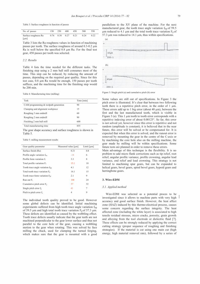
parallelism to the XY plane of the machine. For the next manufactured gear, the tooth trace angle variation fHβ of 59.5 μm reduced to 4.1 μm and the total tooth trace variation Fβ of 57.3 μm was reduced to 14.1 μm, thus within specifications.
Figure 3: Single pitch (a) and cumulative pitch (b) error
Some values are still out of specifications. In Figure 3 the pitch error is illustrated. It’s clear that between two following teeth there is a repetitive pitch error, in the order of 1 μm. These errors add up to 1 big error (about 40 μm), between the first and the last manufactured tooth, which is visible in Figure 3 (a). This 1 μm tooth to tooth error corresponds with a repetitive indexing error of about 0.00125°. So far, this error is not solved yet, however since this error is repetitive and not random (amplitude is constant), it is believed that in the near future, this error will be solved or be compensated for. It is expected that when this error is solved, and the runout error is removed by mounting the gear in the centre of the C-axis or by machining the core hole also on the milling machine, the gear made by milling will be within specifications. Some future tests are planned in order to remove these errors. Main advantage of this technique is the flexibility. It is no problem to add micro flank corrections such as tip relief, root relief, angular profile variance, profile crowning, angular lead variance, end relief and lead crowning. This strategy is not limited to machining spur gears, but can be expanded to helical gears, bevel gears, spiral bevel gears, hypoid gears and herringbone gears.
3. Wire-EDM
3.1. Applied method
Wire-EDM was selected as a potential proces to be investigated since it allows to machine parts with very high accuracy and good surface finish. However, the heat affect zone (HAZ) induced by this thermo-electrical process, causes some concern regarding the surface integrity. The heat affected zone (including the white layer) is associated to high tensile residual stresses, micro cracks, porosity, grain growth and alloying from the tool electrode or dielectric fluid [7]. These effects can be strongly reduced by applying the correct cutting strategy (proper sequence of roughing and finishing strategies). If the material is cut using one main cut (high energy, high material removal rate), followed by a series of
(a)
(b)
80 Jan Bouquet et al. / Procedia CIRP 14 ( 2014 ) 77 – 82
subsequent trim cuts for a high quality finish, these effects are strongly reduced or even absent. Also the type of dielectric has its influence on the surface finish and integrity. Oil based dielectric results in better surface quality, but the cutting process is slower compared to water as a dielectric [7]. The thickness of the remaining HAZ can be detected measuring the depth of the tensile residual stress. For the machining of ASP 2023 tool steel, the HAZ thickness can be reduced from 30 μm after the main cut, to 20 μm after the rough cut and to 5 μm after the finishing cut [7], using an oil based dielectric. When using water as a dielectric, the HAZ thickness is 27 μm, 17 μm, and 7 μm respectively. The surface roughness after the main cut is about 3 μm Ra using water as a dielectric and 4 μm when oil was used as. After the finish trim cut this can be reduced to below 0.5 μm in both cases. The surface roughness required for this application, as listed in table 1, is 0.8 μm Ra thus this should be no problem when using the correct cutting strategy and parameters.
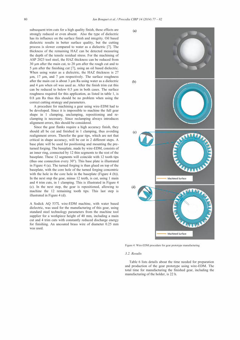
A procedure for machining a gear using wire-EDM had to be developed. Since it is impossible to machine the full gear shape in 1 clamping, unclamping, repositioning and re-clamping is necessary. Since reclamping always introduces alignment errors, this should be considered.
Since the gear flanks require a high accuracy finish, they should all be cut and finished in 1 clamping, thus avoiding realignment errors. Therefor the gear tips, which are not that critical in shape accuracy, will be cut in 2 different steps. A base plate will be used for positioning and mounting the pre-turned forging. The baseplate, made by wire-EDM, consists of an inner ring, connected by 12 thin segments to the rest of the baseplate. These 12 segments will coincide with 12 tooth tips (thus one connection every 30°). This base plate is illustrated in Figure 4 (a). The turned forging is than glued on top of the baseplate, with the core hole of the turned forging concentric with the hole in the core hole in the baseplate (Figure 4 (b)). In the next step the gear, minus 12 teeth, is cut, using 1 main and 4 trim cuts, in 1 clamping. This is illustrated in Figure 4 (c). In the next step, the gear is repositioned, allowing to machine the 12 remaining tooth tips. This last step is illustrated in Figure 4 (d). A Sodick AQ 537L wire-EDM machine, with water based dielectric, was used for the manufacturing of this gear, using standard steel technology parameters from the machine tool supplier for a workpiece height of 40 mm, including a main cut and 4 trim cuts with constantly reduced discharge energy for finishing. An uncoated brass wire of diameter 0.25 mm was used.
Figure 4: Wire-EDM procedure for gear prototype manufacturing
3.2. Results
Table 6 lists details about the time needed for preparation and production of the gear prototype using wire-EDM. The total time for manufacturing the finished gear, including the manufacturing of the holder, is 22 h.
81 Jan Bouquet et al. / Procedia CIRP 14 ( 2014 ) 77 – 82
Table 6: Manufacturing time (EDM)
Task Time [min]
CAM programming 90
Manufacturing of the tool holder 200
Positioning and gluing 15
Main cut 400
Trim cut 530
Repositioning and gluing 15
Removing of the remaining tips 70
Total machining time 1320
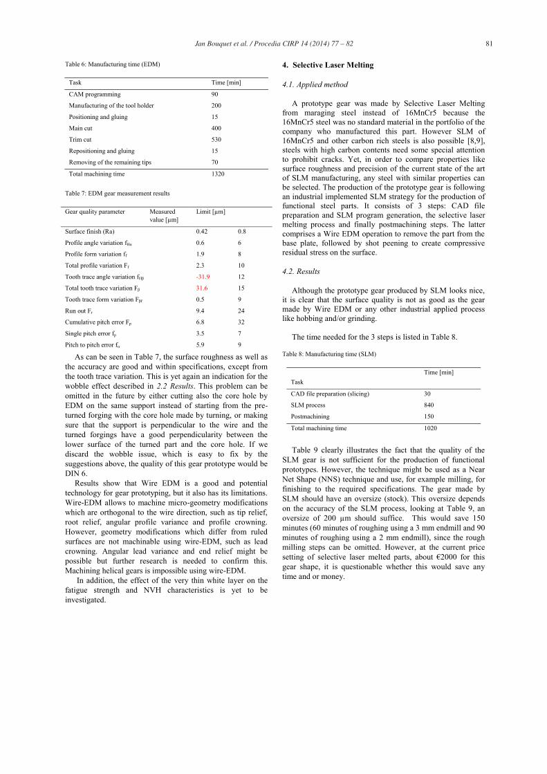
Table 7: EDM gear measurement results
Gear quality parameter Measured value [μm]
Limit [μm]
Surface finish (Ra) 0.42 0.8
Profile angle variation fHα 0.6 6
Profile form variation ff 1.9 8
Total profile variation Ff 2.3 10
Tooth trace angle variation fHβ -31.9 12
Total tooth trace variation Fβ 31.6 15
Tooth trace form variation Fβf 0.5 9
Run out Fr 9.4 24
Cumulative pitch error Fp 6.8 32
Single pitch error fp 3.5 7
Pitch to pitch error fu 5.9 9
As can be seen in Table 7, the surface roughness as well as the accuracy are good and within specifications, except from the tooth trace variation. This is yet again an indication for the wobble effect described in 2.2 Results. This problem can be omitted in the future by either cutting also the core hole by EDM on the same support instead of starting from the pre-turned forging with the core hole made by turning, or making sure that the support is perpendicular to the wire and the turned forgings have a good perpendicularity between the lower surface of the turned part and the core hole. If we discard the wobble issue, which is easy to fix by the suggestions above, the quality of this gear prototype would be DIN 6.
Results show that Wire EDM is a good and potential technology for gear prototyping, but it also has its limitations. Wire-EDM allows to machine micro-geometry modifications which are orthogonal to the wire direction, such as tip relief, root relief, angular profile variance and profile crowning. However, geometry modifications which differ from ruled surfaces are not machinable using wire-EDM, such as lead crowning. Angular lead variance and end relief might be possible but further research is needed to confirm this. Machining helical gears is impossible using wire-EDM.
In addition, the effect of the very thin white layer on the fatigue strength and NVH characteristics is yet to be investigated.
4. Selective Laser Melting
4.1. Applied method
A prototype gear was made by Selective Laser Melting from maraging steel instead of 16MnCr5 because the 16MnCr5 steel was no standard material in the portfolio of the company who manufactured this part. However SLM of 16MnCr5 and other carbon rich steels is also possible [8,9], steels with high carbon contents need some special attention to prohibit cracks. Yet, in order to compare properties like surface roughness and precision of the current state of the art of SLM manufacturing, any steel with similar properties can be selected. The production of the prototype gear is following an industrial implemented SLM strategy for the production of functional steel parts. It consists of 3 steps: CAD file preparation and SLM program generation, the selective laser melting process and finally postmachining steps. The latter comprises a Wire EDM operation to remove the part from the base plate, followed by shot peening to create compressive residual stress on the surface.
4.2. Results
Although the prototype gear produced by SLM looks nice, it is clear that the surface quality is not as good as the gear made by Wire EDM or any other industrial applied process like hobbing and/or grinding.
The time needed for the 3 steps is listed in Table 8.
Table 8: Manufacturing time (SLM)
Task
Time [min]
CAD file preparation (slicing) 30
SLM process 840
Postmachining 150
Total machining time 1020
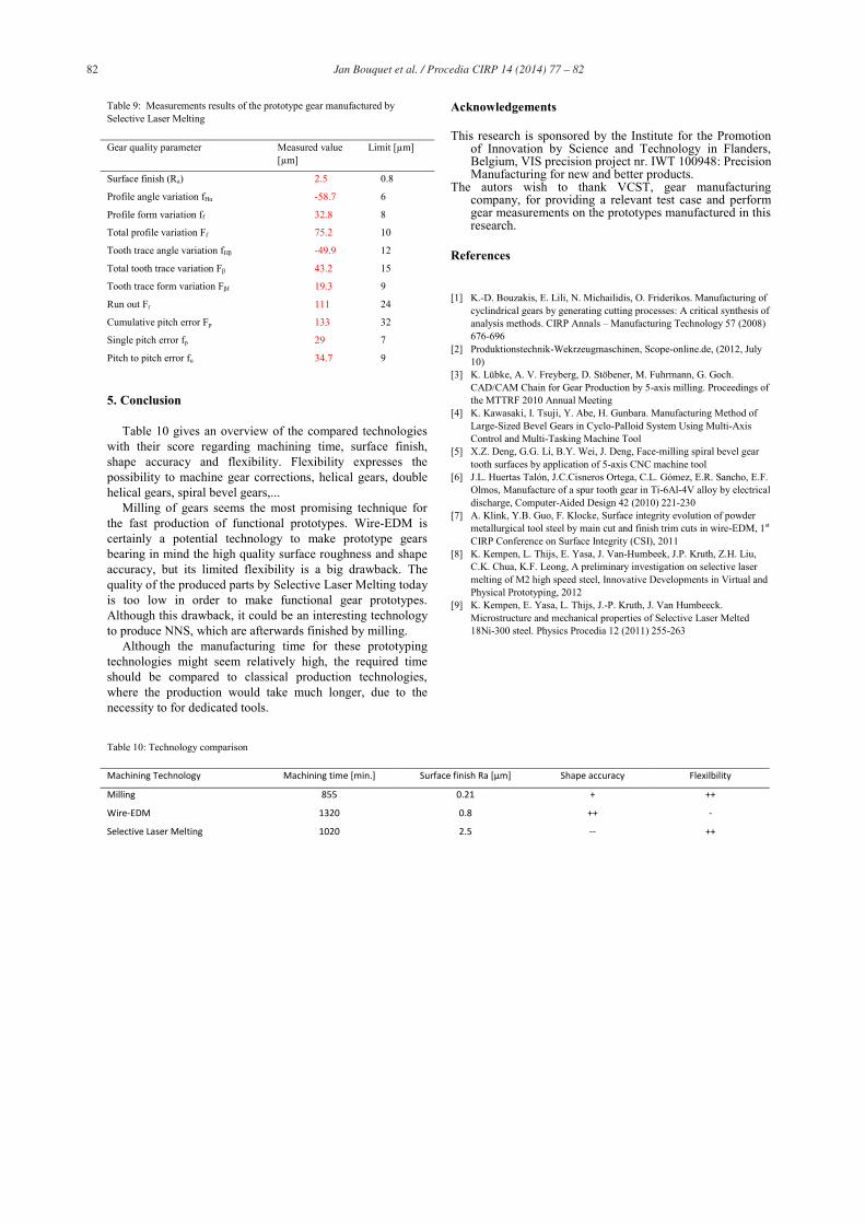
Table 9 clearly illustrates the fact that the quality of the
SLM gear is not sufficient for the production of functional prototypes. However, the technique might be used as a Near Net Shape (NNS) technique and use, for example milling, for finishing to the required specifications. The gear made by SLM should have an oversize (stock). This oversize depends on the accuracy of the SLM process, looking at Table 9, an oversize of 200 μm should suffice. This would save 150 minutes (60 minutes of roughing using a 3 mm endmill and 90 minutes of roughing using a 2 mm endmill), since the rough milling steps can be omitted. However, at the current price setting of selective laser melted parts, about €2000 for this gear shape, it is questionable whether this would save any time and or money.
82 Jan Bouquet et al. / Procedia CIRP 14 ( 2014 ) 77 – 82
Table 9: Measurements results of the prototype gear manufactured by Selective Laser Melting
Gear quality parameter Measured value [μm]
Limit [μm]
Surface finish (Ra) 2.5 0.8
Profile angle variation fHα -58.7 6
Profile form variation ff 32.8 8
Total profile variation Ff 75.2 10
Tooth trace angle variation fHβ -49.9 12
Total tooth trace variation Fβ 43.2 15
Tooth trace form variation Fβf 19.3 9
Run out Fr 111 24
Cumulative pitch error Fp 133 32
Single pitch error fp 29 7
Pitch to pitch error fu 34.7 9
5. Conclusion
Table 10 gives an overview of the compared technologies with their score regarding machining time, surface finish, shape accuracy and flexibility. Flexibility expresses the possibility to machine gear corrections, helical gears, double helical gears, spiral bevel gears,...
Milling of gears seems the most promising technique for the fast production of functional prototypes. Wire-EDM is certainly a potential technology to make prototype gears bearing in mind the high quality surface roughness and shape accuracy, but its limited flexibility is a big drawback. The quality of the produced parts by Selective Laser Melting today is too low in order to make functional gear prototypes. Although this drawback, it could be an interesting technology to produce NNS, which are afterwards finished by milling.
Although the manufacturing time for these prototyping technologies might seem relatively high, the required time should be compared to classical production technologies, where the production would take much longer, due to the necessity to for dedicated tools.
Acknowledgements
This research is sponsored by the Institute for the Promotion of Innovation by Science and Technology in Flanders, Belgium, VIS precision project nr. IWT 100948: Precision Manufacturing for new and better products.
The autors wish to thank VCST, gear manufacturing company, for providing a relevant test case and perform gear measurements on the prototypes manufactured in this research.
References
[1] K.-D. Bouzakis, E. Lili, N. Michailidis, O. Friderikos. Manufacturing of
cyclindrical gears by generating cutting processes: A critical synthesis of analysis methods. CIRP Annals – Manufacturing Technology 57 (2008) 676-696
[2] Produktionstechnik-Wekrzeugmaschinen, Scope-online.de, (2012, July 10)
[3] K. Lübke, A. V. Freyberg, D. Stöbener, M. Fuhrmann, G. Goch. CAD/CAM Chain for Gear Production by 5-axis milling. Proceedings of the MTTRF 2010 Annual Meeting
[4] K. Kawasaki, I. Tsuji, Y. Abe, H. Gunbara. Manufacturing Method of Large-Sized Bevel Gears in Cyclo-Palloid System Using Multi-Axis Control and Multi-Tasking Machine Tool
[5] X.Z. Deng, G.G. Li, B.Y. Wei, J. Deng, Face-milling spiral bevel gear tooth surfaces by application of 5-axis CNC machine tool
[6] J.L. Huertas Talón, J.C.Cisneros Ortega, C.L. Gómez, E.R. Sancho, E.F. Olmos, Manufacture of a spur tooth gear in Ti-6Al-4V alloy by electrical discharge, Computer-Aided Design 42 (2010) 221-230
[7] A. Klink, Y.B. Guo, F. Klocke, Surface integrity evolution of powder metallurgical tool steel by main cut and finish trim cuts in wire-EDM, 1st CIRP Conference on Surface Integrity (CSI), 2011
[8] K. Kempen, L. Thijs, E. Yasa, J. Van-Humbeek, J.P. Kruth, Z.H. Liu, C.K. Chua, K.F. Leong, A preliminary investigation on selective laser melting of M2 high speed steel, Innovative Developments in Virtual and Physical Prototyping, 2012
[9] K. Kempen, E. Yasa, L. Thijs, J.-P. Kruth, J. Van Humbeeck. Microstructure and mechanical properties of Selective Laser Melted 18Ni-300 steel. Physics Procedia 12 (2011) 255-263
Table 10: Technology comparison
Machining Technology Machining time [min.] Surface finish Ra [μm] Shape accuracy Flexilbility
Milling 855 0.21 + ++
Wire-EDM 1320 0.8 ++ -
Selective Laser Melting 1020 2.5 -- ++