production switcher system - s-pro.tv switcher system dvs-9000/9000sf system (with ccp-9000 series)...
TRANSCRIPT

ProductionSw
itcher System
DV
S-9000/9000S
F S
ystem (W
ith C
CP
-9000 Series)
ProductionSwitcher System
DVS-9000/9000SF System(With CCP-9000 Series Center Control Panel)
User’s Guide [English]
Volume 32nd Edition
4-136-339-01 (1)
User’s GuideVolume 3
2nd Edition
[ English ]

DVS-9000/9000SF System (With CCP-9000 Series Center Control Panel)
User’s Guide
Production Switcher System
Volume 3 [English]
2nd EditionSoftware Version 8.00 and Later

NOTICE TO USERS© 2002 Sony Corporation. All rights reserved. This manual or the software described herein, in whole or in part, may not be reproduced, translated or reduced to any machine readable form without prior written approval from Sony Corporation.
SONY CORPORATION PROVIDES NO WARRANTY WITH REGARD TO THIS MANUAL, THE SOFTWARE OR OTHER INFORMATION CONTAINED HEREIN AND HEREBY EXPRESSLY DISCLAIMS ANY IMPLIED WARRANTIES OF MERCHANTABILITY OR FITNESS FOR ANY PARTICULAR PURPOSE WITH REGARD TO THIS MANUAL, THE SOFTWARE OR SUCH OTHER INFORMATION. IN NO EVENT SHALL SONY CORPORATION BE LIABLE FOR ANY INCIDENTAL, CONSEQUENTIAL OR SPECIAL DAMAGES, WHETHER BASED ON TORT, CONTRACT, OR OTHERWISE, ARISING OUT OF OR IN CONNECTION WITH THIS MANUAL, THE SOFTWARE OR OTHER INFORMATION CONTAINED HEREIN OR THE USE THEREOF.
Sony Corporation reserves the right to make any modification to this manual or the information contained herein at any time without notice.The software described herein may also be governed by the terms of a separate user license agreement.

<Organization of This User’s Guide>The User’s Guide for this system comprises Volumes 1 to 3.
Volume 1The volume comprises the following chapters.Chapter 1 DVS-9000 FunctionsChapter 2 Menus and Control PanelChapter 3 Signal Selection and TransitionsChapter 4 KeysChapter 5 WipesChapter 6 DME WipesChapter 7 Frame MemoryChapter 8 Color Backgrounds, Copy and Swap, and Other SettingsChapter 9 Color CorrectorChapter 10 Special FunctionsAppendix (Volume 1)
• Wipe Pattern List• DME Wipe Pattern List• Menu Tree
Index
Volume 2The volume comprises the following chapters.Chapter 11 DME OperationsChapter 12 External DevicesChapter 13 Keyframe EffectsChapter 14 SnapshotsChapter 15 Utility/ShotboxChapter 16 MacrosChapter 17 FilesAppendix (Volume 2)
• SpotLighting• Functional Differences With Models of DME• Macro File Editing Rules• About the Macro Attachment List Display• Menu Operations Not Recorded in a Menu Macro
Index
Volume 3This book. For the contents of this volume, see “Table of Contents” at the front.Chapter 18 System Setup (System)Chapter 19 Control Panel Setup (Panel)Chapter 20 Switcher Setup (Switcher)Chapter 21 DME Setup (DME)Chapter 22 DCU Setup (DCU)Chapter 23 Setup Relating to Router Interface and Tally (Router/Tally)
3

4
Chapter 24 Simple Connection of the MKS-8080/8082 AUX Bus Remote Panel
Chapter 25 DIAGNOSISAppendix (Volume 3)
• Data Saved by [Setup Define] and [Initial Status Define]• Error Messages
Index

Table of Contents
Chapter 18 System Setup (System)
Setup for the Whole System.........................................................................12Network Settings (Network Config Menu).................................................13
Making the Network Settings................................................................13System Settings (System Config Menu)......................................................14
Selecting the System Operation Mode ..................................................14Specifying the Switcher Controlled by the Control Panel ....................15Specifying the DME Connected to the Switcher...................................16
Setting the Signal Format (Format Menu).................................................17Setting the Signal Format ......................................................................17
Setting the Screen Aspect Ratio (Format Menu).......................................19Selecting the State After Powering On (Start Up Menu)..........................20
Saving and Recalling Setup Data ..........................................................21Selecting the State at Start-up ...............................................................22Saving User-Defined Settings ...............................................................23Setting Automatic Loading of Register Data at Power On (Autoload
Function) ....................................................................................23Reset and Initialization (Initialize Menu)...................................................25Installation and Device Setup (Install/Unit Config Menu) .......................26
Installing Software ................................................................................26Making Settings Required to Use the Software ....................................28Adding User Texture Patterns ...............................................................31Switching the Color Correction Function .............................................38
System Maintenance (Maintenance Menu)................................................39Setting the Date and Time .....................................................................39Using a Memory Card ...........................................................................40Carrying Out the Primary Setting..........................................................40Reloading a USB Driver........................................................................41Initializing the Hard Disk ......................................................................41Locking the Setup Menu Settings .........................................................42
Chapter 19 Control Panel Setup (Panel)
Overall Control Panel Settings (Config Menu)..........................................50Panel Setup ............................................................................................50
5Table of Contents

6
Interchanging the Bank Order or Disabling Operation .........................51Assigning Two M/E Banks to One M/E Bank ......................................52Assigning the Key Delegation in the Downstream Key Control Block
(MKS-8032 DSK Fader Module, Option) .................................53Linking Switcher Bus and Router Destination......................................54Linking Transitions Between Keyers ....................................................57Linking the Next Transition Selection Buttons .....................................57Selecting the Module to be the Reference for Device Control Block ...58Assigning a Region to a Region Selection Button in the Numeric Keypad
Control Block.............................................................................58Setting the Assignment of Transition Type Selection Buttons .............60Setting VTR Operation Button Assignment..........................................61Setting the Assignment of Macro Operation Buttons ...........................63Assigning Keys to the DSK1 and DSK2 Buttons in the Downstream Key/
Fade-to-Black Control Block .....................................................63Assigning Keys to the Independent Key Transition Control Block
(Simple Type) ............................................................................64Assigning Preview Output to Preview Selection Buttons .....................66Assigning Functions to the Device Control Block ................................67Inhibiting Utility 2 Bus and Key Operations.........................................69Assigning Functions to the Menu Control Block Top Menu and User
Preference Buttons .....................................................................69Cross-Point Settings (Xpt Assign Menu) ....................................................71
Creating Cross-Point Assign Tables......................................................71Copying Cross-Point Assign Tables......................................................77Selecting Cross-Point Assign Tables ....................................................78Exporting Source Names and Destination Names.................................79Making Settings for Audio Mixer .........................................................79
Auxiliary Bus Control Block Settings (Aux Assign Menu).......................81Assigning a Bus to an AUX Delegation Button....................................81Using the Auxiliary Bus Control Block for Router Control .................82
Setting Button Assignments (Prefs/Utility Menu) .....................................87Assigning Functions to User Preference Buttons..................................87Assigning a Function to a Memory Recall Button in the Utility/Shotbox
Control Block (MKS-8033 Utility/Shotbox Module, Option)...92Interfacing With External Devices (Device Interface Menu) ...................98
Making Control Panel GPI Input Settings.............................................98Making Control Panel GPI Output Settings ........................................101Setting the Control Mode for P-Bus Devices ......................................103
Table of Contents

Setting the SCU Editor Panel Port ......................................................103Making DCU Serial Port Settings .......................................................104Sharing Disk Recorder/Extended VTR File Lists ...............................105
Operation Settings (Operation Menu)......................................................106Setting the On-Air Tally......................................................................107Setting the Transition Rate Display Mode ..........................................107Making Settings Relating to Effects....................................................107Setting the First Keyframe When a Rewind is Executed ....................108Setting the Source and Destination Names .........................................108Settings for the Wipe Snapshot Menu .................................................109Setting the Button Operation Mode.....................................................110Setting Trackball, Joystick, Search Dial, and Double-Click Sensitivity...
111Specifying Main Split Fader................................................................112Setting the Macro Execution Mode.....................................................112
Screen Saver and Other Settings (Maintenance Menu)..........................114Screen Saver Settings ..........................................................................114Adjusting the Brightness .....................................................................114Adjusting the Alarms...........................................................................115Calibrating the Touch Panel ................................................................115Setting the Menu to be Shown When the Menus Are Started.............116Selecting the Mouse Button Used for Adjusting the Knob Parameters ....
116
Chapter 20 Switcher Setup (Switcher)
Settings for Switcher Configuration (Config Menu)...............................119Adjusting the Reference Phase............................................................120Specifying the Video Switching Timing .............................................120Setting the Operation Mode ................................................................120Setting User Regions ...........................................................................123Assigning PGM/PST Logically to an M/E..........................................123Setting the Assignments of DME Channels to Use on the Individual M/E
Banks........................................................................................124Signal Input Settings (Input Menu) ..........................................................125
Making Phase Adjustment and Through Mode Settings.....................125Making Video Process Settings...........................................................126Enabling the Illegal Color Limiter ......................................................126
Signal Output Settings (Output Menu) ....................................................127Assigning Output Signals ....................................................................127
7Table of Contents

8
Setting the Reference Output ..............................................................128Setting the Output Signal ....................................................................129
Settings Relating to Video Switching (Transition Menu) .......................132Selecting the Bank to Make the Settings.............................................132
Settings Relating to Keys, Wipes, Frame Memory and Color Correction (Key/Wipe/FM/CCR Menu)...........................................................135
Switching Video Process Memory On or Off .....................................135Settings for the Show Key Function....................................................136Settings for Key Auto Drop Function .................................................136Automatically Naming and Saving to Frame Memory .......................137Selecting the Bank to Make the Settings.............................................137
Settings Relating to Function Links (Link Menu)...................................140Setting a Cross-Point Button Link.......................................................140Making Link Table Settings ................................................................142Linking Cross-Point Buttons and GPI Output Ports ...........................142Making a Setting for Linking Two M/E Banks...................................144Making a Link Setting for Key Transition ..........................................145
Interfacing With External Devices (Device Interface Menu) .................147Making 9-Pin Port Device Interface Settings......................................147Making Switcher Processor GPI Input Settings ..................................148Making Switcher Processor GPI Output Settings ...............................151Enabling or Disabling AUX Bus Control............................................152Setting the Interface Between the DME and the Switcher ..................153Setting the AUX Bus Output and Reentry Input .................................154Selecting the Mode for Turning Off Keys Upon Receiving the Editor
Command .................................................................................155
Chapter 21 DME Setup (DME)
Settings Relating to Signal Inputs (Input Menu).....................................158Setting the Initial Crop ........................................................................158Setting an Illegal Color Limit for Matte Signals .................................159Making DME System Phase Adjustment ............................................159Setting the TBC Window Center Position ..........................................159
Settings Relating to Signal Outputs (Output Menu) ...............................161Adjusting the Monitor Output .............................................................161Setting the Monitor Output..................................................................162
Interfacing With External Devices (Device Interface Menu) .................163Making DME GPI Input Settings ........................................................164Making DME GPI Output Settings .....................................................166
Table of Contents

Chapter 22 DCU Setup (DCU)
Setup Relating to DCU...............................................................................168Settings Relating to Parallel Inputs (Input Config Menu)......................169
Assigning a GPI Input Port .................................................................169Releasing the Assignment of a GPI Input Port....................................170
GPI Input Setting (GPI Input Assign Menu)...........................................171Making DCU GPI Input Settings ........................................................171
Parallel Output Settings (Output Config Menu) .....................................175Assigning a GPI Output Port...............................................................175Releasing the Assignment of a GPI Output Port .................................176
GPI Output Setting (GPI Output Assign Menu) .....................................177Making DCU GPI Output Settings......................................................177
Serial Port Settings (Serial Port Assign Menu) .......................................180Making Serial Port Settings.................................................................180Making Detailed Settings on the External Device Connected to the Serial
Port ...........................................................................................182
Chapter 23 Setup Relating to Router Interface and Tally (Router/Tally)
Router Interface Settings (Router Menu) ................................................192Assigning Switcher Inputs and Outputs to S-Bus Space.....................192Making an External Box Setting .........................................................193
Tally Group Settings (Group Tally Menu) ..............................................196Wiring Settings (Wiring Menu) ................................................................197
Making New Wiring Settings..............................................................197Changing the Wiring Settings .............................................................198Deleting Wiring Settings .....................................................................198Sorting Wiring Settings .......................................................................198
Tally Generation Settings (Tally Enable Menu)......................................200Making New Tally Generation Settings ..............................................200Modifying Tally Generation................................................................201Deleting Tally Generation Settings .....................................................201
Tally Copy Settings (Tally Copy Menu)...................................................203Making New Tally Copy Settings .......................................................203Modifying Tally Copy Settings ...........................................................204Deleting Tally Copy Settings ..............................................................204
Parallel Tally Settings (Parallel Tally Menu) ..........................................205Making or Modifying Parallel Tally Settings......................................205Deleting Parallel Tally Settings...........................................................206
Serial Tally Settings (Serial Tally Menu) .................................................207
9Table of Contents

10
Setting or Changing the Serial Tally Settings .....................................207Making the Serial Tally Source Address Settings...............................207Clearing a Source Address Setting ......................................................208
Chapter 24 Simple Connection of the MKS-8080/8082 AUX Bus Remote Panel
Procedure for Simple Connection.............................................................210Setting Status of the MKS-8080/8082 in Simple Connection..................212
Chapter 25 DIAGNOSIS
Checking the Communications Status......................................................214Communications Status Display .........................................................214
Appendix (Volume 3)
Data Saved by [Setup Define] and [Initial Status Define].......................218Data Saved by [Setup Define] .............................................................218Data Saved by [Initial Status Define]..................................................223
Error Messages ...........................................................................................226Error Messages Displayed in the Error Status/Error Log Menu .........226Error Messages Appearing in a Message Box.....................................231Error Messages Shown in the Error Information Menu ......................239
Index ...........................................................................................................241
Table of Contents

Chapter 18 System Setup (System)
Setup for the Whole System .......................................................................12Network Settings (Network Config Menu) ...............................................13
Making the Network Settings ..............................................................13System Settings (System Config Menu) ....................................................14
Selecting the System Operation Mode ................................................14Specifying the Switcher Controlled by the Control Panel ..................15Specifying the DME Connected to the Switcher .................................16
Setting the Signal Format (Format Menu) ...............................................17Setting the Signal Format ....................................................................17
Setting the Screen Aspect Ratio (Format Menu) .....................................19Selecting the State After Powering On (Start Up Menu) ........................20
Saving and Recalling Setup Data ........................................................21Selecting the State at Start-up .............................................................22Saving User-Defined Settings .............................................................23Setting Automatic Loading of Register Data at Power On (Autoload
Function) ..................................................................................23Reset and Initialization (Initialize Menu) .................................................25Installation and Device Setup (Install/Unit Config Menu) .....................26
Installing Software ..............................................................................26Making Settings Required to Use the Software ..................................28Adding User Texture Patterns .............................................................31Switching the Color Correction Function ...........................................38
System Maintenance (Maintenance Menu) ..............................................39Setting the Date and Time ...................................................................39Using a Memory Card .........................................................................40Carrying Out the Primary Setting ........................................................40Reloading a USB Driver ......................................................................41Initializing the Hard Disk ....................................................................41Locking the Setup Menu Settings .......................................................42

Chapter 18
System
Setup (S
ystem)
12
Setup for the Whole System
Carry out operations relating to setup for the whole system in the Engineering Setup menu.To access the Engineering Setup menu, press the top menu selection button [ENG SETUP].Here the “whole system” refers to all devices connected on the Control LAN.The DCU is connected through the control panel, but is also included in the “whole system.”
For an overview of setup, see “Setup” in Chapter 1 (Volume 1).
Setting the unit IDWhen there are two switchers and connected DME units on the same network, it is necessary to set the unit ID on each device, as follows.
For more details of how to make the unit ID settings, refer to the installation manual for the particular device.
Switcher ID
1st switcher 1
2nd switcher 2
DME ID
DME1 for 1st switcher (channels 1 to 4) 1
DME2 for 1st switcher (channels 5 to 8) 2
DME1 for 2nd switcher (channels 1 to 4) 3
DME2 for 2nd switcher (channels 5 to 8) 4
Setup for the Whole System

Chapter 18
System
Setup (S
ystem)
Network Settings (Network Config Menu)
This provides automatic configuration of all devices connected to the Data LAN (excluding the DCU), and displays a list of them.To make the network settings, use System >Network Config menu.
To display the Network Config menuIn the Engineering Setup menu, select VF1 ‘System’ and HF1 ‘Network Config.’The status area shows the device ID, and Control LAN and Data LAN IP addresses for each device excluding the DCU.
Making the Network Settings
1 In the System >Network Config menu, press [Auto Config].
This automatically checks all devices (excluding the DCU) connected to the Data LAN.
2 Once switch to another menu, then display the Network Config menu again.
Now the status area of the System >Network Config menu shows the results of the automatic check.
NoteBe sure to carry out this operation after reconfiguring the system, or after a software upgrade.
13Network Settings (Network Config Menu)

Chapter 18
System
Setup (S
ystem)
14
System Settings (System Config Menu)
Specify the overall system operation mode and the hierarchical relationship of the devices.To make the system settings, use the System >System Config menu.
To display the System Config menuIn the Engineering Setup menu, select VF1 ‘System’ and HF2 ‘System Config.’
NoteAfter changing any of the following settings, be sure to press [Execute] to save the new values. If you want to cancel the setting changes without saving them, press [Clear].
Selecting the System Operation Mode
In the <Operation Mode> group of the System >System Config menu, select one of the following.• Single Proc mode: The control panel controls a single switcher.• Dual Simul mode: The control panel controls two switchers simultaneously.
Notes• Single Simul mode is disabled for the CCP-9000/9000A.• When operating an MVS-8000 system and a DVS-9000 system in Dual
Simul mode, simultaneous operation may not be possible because of differences between the systems in some functions.
• For an MVS-8000 system, SD systems and HD systems store different numbers of frames in frame memory. When operating an SD system and an HD system in Dual Simul mode, use the HD system (which stores fewer frames) as the first system (the system whose switcher ID is 1).
Device hierarchical relationship setting• Panel Assign: Specify the switcher controlled by a control panel.• Switcher Assign: Specify the DME connected to a switcher.
System Settings (System Config Menu)

Chapter 18
System
Setup (S
ystem)
Specifying the Switcher Controlled by the Control Panel
1 In the System >System Config menu, press the [Panel Assign] button.
The Panel Assign menu appears.
2 Select the switcher to be controlled by the selected control panel, as follows.
• If there is only one switcher on the network, in the <1st Switcher> group, set [SWR1] to On, and in the <2nd Switcher> group, set [SWR2] to Off.
• If there are two switchers on the same network, in the <1st Switcher> group, select the switcher to be operated.When the system operation mode (see previous item) is set to [Dual Simul], the switcher status set in <1st Switcher> appears on the control panel.
3 To set the selected control panel as tally control master panel, press [Tally Master], turning it on.
If there are multiple panels and processors, the control panel for which [Tally Master] is set to On carries out tally control for the whole system.
NoteWhen there are multiple control panels, make sure that one of them has [Tally Master] set to On. When you change the master panel, be sure to copy and save the setup tally (TLY) and router (RTR) data in the File menu, and make the same settings for other panels.
To select the lighting mode of the switcher bus selection buttons on the remote panelWhen switching buses with the MKS-8080/8082 AUX Bus Remote Panel or other remote panel connected via S-Bus data link, you can select the lighting mode of the bus selection buttons.In the System >System Config >Panel Assign menu, select either of the following in the <S-Bus Remote Sw'er Status> group.Mode 1: The inhibited buttons do not light even when pressed, and the other
buttons light after a longer delay time than in Mode 2.Mode 2: The delay time for button lighting is reduced, but even the inhibited
buttons may light for a moment when pressed.
Notes• Make sure that [Tally Master] is set to On.• When simple connection is used between the center control panel and remote
panel, this setting is disabled.
15System Settings (System Config Menu)

Chapter 18
System
Setup (S
ystem)
16
Specifying the DME Connected to the Switcher
1 In the System >System Config menu, press [Switcher Assign].
The Switcher Assign menu appears.
2 Using either of the following methods, select the switcher to which the settings apply.
• In the list appearing in the menu, press the desired device name.• Press the arrow keys to scroll the reverse video cursor.
The selected switcher appears in reverse video.If there is only one switcher on the network, carry out the SWR1 setting (for the first switcher) only.
3 Make the DME settings as follows.
• When making DME settings for SWR1 (the first switcher), for the first DME, select [DME1] in the <1st DME> group.Turn all buttons in the <2nd DME> group off.
• When making DME settings for SWR2 (the second switcher), for the first DME, select [DME3] in the <1st DME> group. Turn all buttons in the <2nd DME> group off.
Setup in “Dual Simul” modeWhen the system operation mode (see page 14) is set to “Dual Simul,” the following setting is required for setup of the two switchers and connected DME units.In the <Setup Target> group, set the [System 1] or [System 2] button to On, then carry out the setup. You can also set both to On, and make the settings simultaneously on the two systems.
System Settings (System Config Menu)

Chapter 18
System
Setup (S
ystem)
Setting the Signal Format (Format Menu)
To set the format, that is, the frame frequency and number of scan lines handled by each device, use the System >Format menu.
To display the Format menuIn the Engineering Setup menu, select VF1 ‘System’ and HF3 ‘Format.’
NoteAfter changing any of the following settings, be sure to press [Execute] to save the new values. If you want to cancel the settings and return to the original state, press [Clear] without pressing [Execute].
Setting the Signal Format
Specify the signal format to be handled by the devices.The combinations of signal formats that can be selected are as follows.
1 In the System >Format menu, select the device for operations.
• Press directly on the list in the status area.• Press the arrow keys to scroll the reverse video cursor.• Turn the knob.
2 Press [Signal Format].
A pop-up window appears.
System Field frequency Effective number of scan lines
SD system 59.94 480i
50 576i
Knob Parameter Adjustment Setting values
1 Device Selection of device for operations 1 and upwards
17Setting the Signal Format (Format Menu)

Chapter 18
System
Setup (S
ystem)
18
3 Press the button for the desired signal format.
Setting the Signal Format (Format Menu)

Chapter 18
System
Setup (S
ystem)
Setting the Screen Aspect Ratio (Format Menu)
Switch the screen aspect ratio to 4:3 or 16:9.To set the screen aspect ratio, use the System >Format menu.
Setting the screen aspect ratio
1 In the System >Format menu, press [Aspect].
The Aspect menu appears.
2 In the <Screen Aspect> group, select one of the following.
• 16:9• 4:3• Independ: Set the screen aspect ratio separately for M/E, P/P, and USER
on the switcher, and for each channel independently on the DME.
3 If you selected [Independ] in step 2, select from the following.
Switcher Aspect: Make the setting for the switcher.DME Aspect: Make the setting for the DME.
A menu appears according to the selection.
4 Carry out either of the following, depending on the selection you made in step 3.
When you selected [Switcher Aspect]: In each of the <M/E-1>, <M/E-2>, <M/E-3>, <P/P>, and <USER> groups, select either [16:9] or [4:3].
When you selected [DME Aspect]: For each of the <CH1> to <CH4> groups, select either [16:9] or [4:3].
5 To confirm the above setting, press [Aspect Execute].To cancel the setting and return to the original state, press [Clear] without pressing [Aspect Execute].
When you press [Aspect Execute], a confirmation message appears.
6 Press [Yes].
This saves the screen aspect ratio setting.
19Setting the Screen Aspect Ratio (Format Menu)

Chapter 18
System
Setup (S
ystem)
20
Selecting the State After Powering On (Start Up Menu)
Set the initial state of the devices when the system is powered on.For each device, you can select Resume mode or Custom mode.
Resume modeThis resumes the setting state at the previous power-off operation. This setting is only available for the switcher processor and panel.
Custom modeThis uses the settings saved in non-volatile memory or ROM within the device. In this mode, there are Setup and Initial Status settings which can be set separately.• Setup mode: Select the setup state to be used after powering on from the
following.User: Start up using the user data previously saved with [Setup Define].Factory: Start up with the factory default settings.
• Initial status mode: Select the state of each device after powering on (excluding the settings to which “setup” applies).
User: Start up using the user data previously saved with [Initial Status Define]. For the control panel, this applies to the key bus delegation buttons only.
Factory: Start up with the factory default settings.
For details of saving and recalling setup data, see “Saving and Recalling Setup Data” (page 21) and the appendix “Data Saved by [Setup Define] and [Initial Setup Define]” (Volume 2).
Autoload functionSwitch on or off the function to automatically load predetermined register data or frame memory image data at power on. Set the data to be read in the File menu.
Selecting the State After Powering On (Start Up Menu)

Chapter 18
System
Setup (S
ystem)
Saving and Recalling Setup Data
Concept of saving and recalling setup data
Updating the switcher or control panel setup data saves the updated setup data in RAM in each device.• In Resume mode (see page 20), even if devices are reset or powered off, the
data is preserved in RAM, and recalled when the power is turned back on.
NoteThe Resume mode cannot be used for DMEs and DCUs.
• In Custom mode (see page 20), the user-defined settings (user setup data) saved in non-volatile memory or factory default setup data held in ROM in
Hard disk / memory cardUser setup data
Load Save
File menu: [Load]
File menu: [Save]
Current setup data(If in Resume mode, settings data is saved.)
StoreIn Custom mode, power on or reset
Initialize
User setup data Factory default setup data
Setup menu:[Setup Define]
Setup menu:[All Clear]
RAM
ROM Non-volatile memory
21Selecting the State After Powering On (Start Up Menu)

Chapter 18
System
Setup (S
ystem)
22
each device is recalled when a reset is made or the power is turned back on. (See “Selecting the State at Start-up” (page 22).)
Note that the setup data in RAM can also be saved to the control panel hard disk or memory card.
To set the initial state at start-up, use the System >Start Up menu.
NoteIt is not possible to set the DCU state at start-up, but its settings can be saved in the control panel.
To display the Start Up menuIn the Engineering Setup menu, select VF1 ‘System’ and HF4 ‘Start Up.’The status area shows the current start-up mode settings of each device.
Selecting the State at Start-up
1 In the status area of the System >Start Up menu, select the device to which the settings are to apply.
2 In the <Start Up Mode> group, select one of the following modes.
Resume: When this is on, Resume mode is enabled.Custom: When this is on, Custom mode is enabled.
For information about Resume mode and Custom mode, see “System Setup” in Chapter 1 (Volume 1).
NoteThe Resume mode is only valid when a switcher or control panel is selected for the setting.
3 When Custom mode is selected, in each of the <Setup> group and <Initial Status> group, select one of the following.
User: When this is on, user-defined settings are used for the Setup or Initial Status settings. For the method of saving the user-defined settings, see the next item.
Factory: When this is on, factory default settings are used for the Setup or Initial Status settings.
4 To confirm the settings, press [Execute]. If you want to cancel the setting changes without saving them, press [Clear].
When [Execute] is pressed, a confirmation message appears.
Selecting the State After Powering On (Start Up Menu)
Chapter 18
System
Setup (S
ystem)
5 Select [Yes].
The start-up state settings are saved.
Saving User-Defined Settings
Saving the Setup settings
1 After selecting the devices to which the settings apply to, in the System >Start Up menu, press [Setup Define].
A confirmation message appears.
2 Press [Yes].
This saves the setup settings for the selected devices in non-volatile memory within the respective devices.
For details about the settings which will be saved, see“Data Saved by [Setup Define] and [Initial Status Define]” (page 218).
Saving the Initial Status settings
1 After selecting the devices to which the settings apply to, in the System >Start Up menu, press [Init Status Define].
A confirmation message appears.
2 Press [Yes].
This saves the initial status settings other than the “setup” settings for the selected devices in non-volatile memory within the respective devices.
For details about the settings which will be saved, see “Data Saved by [Setup Define] and [Initial Status Define]” (page 218).
Setting Automatic Loading of Register Data at Power On (Autoload Function)
To have specified data read in at power on, in the System >Start Up menu, press [Power On File Load], turning it on.This enables the autoload function.
23Selecting the State After Powering On (Start Up Menu)

Chapter 18
System
Setup (S
ystem)
24
When the autoload function is enabled, a directory “PWON_LD” appears in the corresponding File menu.
About saving data which can be loaded by the autoload function, see “Saving Files Recalled by Autoload” in Chapter 17 (Volume 2).
Selecting the State After Powering On (Start Up Menu)

Chapter 18
System
Setup (S
ystem)
Reset and Initialization (Initialize Menu)
To carry out a reset or memory initialization for a device, use the System >Initialize menu.• Reset: Reset to state after powering on.• All Clear: Clear the memory, and carry out initialization. The Network
Config, System Config, Format, and Start Up setup values are set by reference to data stored in non-volatile memory, and the system automatically starts up. It is not necessary to reset the Date/Time settings.
For more details, see “Saving and Recalling Setup Data” (page 21).
To display the Initialize menuIn the Engineering Setup menu, select VF1 ‘System’ and HF5 ‘Initialize.’The status area shows the current start-up mode settings.
Resetting the device and initializing memory
1 In the status area of the System >Initialize menu, select the device to which the settings are to apply.
2 In the <Initialize> group, select one of the following modes.
Reset: Reset the device.All Clear: Initialize memory.
3 Press [Execute].
A confirmation message appears.
4 Select [Yes].
Depending on the selection in step 2, the following is the result.• When you selected [Reset], a reset is applied to the device causing it to
be restarted in the start-up state.• When you selected [All Clear], all memory in the device is cleared,
including snapshots, keyframe effects, setup, and so on, and the device returns to its factory default settings. However, the Network Config, Format, Start Up, and Date/Time settings are not initialized.
25Reset and Initialization (Initialize Menu)

Chapter 18
System
Setup (S
ystem)
26
Installation and Device Setup (Install/Unit Config Menu)
To install software or firmware in a device, use the System >Install/Unit Config menu.This installs the software and firmware in all devices (including the DCU) connected to the Data LAN.
To display the Install/Unit Config menuIn the Engineering Setup menu, select VF1 ‘System’ and HF6 ‘Install/Unit Config.’The status area shows the version of the software and the firm ware installed in each device.
The following functions are available here.Install: Automatically detects the software that can be installed on each device,
and installs the selected software.Detail Information: Gives details of the software and firmware installed in
each device.Unit Config: Carries out switcher processor settings. Switches the color
corrector function between secondary color correction and spot color adjustment.
License: Makes the license valid or invalid.
Displaying installation detailsIn the System >Install/Unit Config menu, press [Detail Information].This accesses the Detail Information menu, and displays the detailed information on the software and firmware installed in the currently selected device.
Installing Software
1 Insert the memory card holding the software into the memory card slot.
2 In the System >Install/Unit Config menu, press [Install].
The Install menu appears; the status area shows the following information.Upper list: For each connected device, this shows the device name,
current software version (Current), and the latest version that can be
Installation and Device Setup (Install/Unit Config Menu)

Chapter 18
System
Setup (S
ystem)
installed (Install, Title).OK: Installation already completed.On: For installation, but not completed.Error: An error occurred during installation.Cancel: Installation canceled.
Lower list: For the device selected in the upper list, this shows an automatically detected list of software that can be installed on the particular device. Also, software selected as a candidate for installation in the upper list is marked in the lower list with an bullet.
3 If you are satisfied with the currently installed version of all items in the upper list, skip to step 6.
To change the items to be installed, use any of the following methods to select the relevant device.
• Press directly on the list in the status area.• Use the arrow keys to scroll the reverse video cursor.• Turn the knob.
The display of the lower list changes according to the selected device.
To display all related softwarePress [Display All Software], turning it on.Not just the automatically detected software, but the names of all related software for the selected device appear.
4 In the lower list, select the software you want to install.
• Press directly on the list in the status area.• Use the arrow keys to scroll the reverse video cursor.• Turn the knob.
5 Press [Set].
The selection is reflected under “Install” and “Title” in the upper list.
6 Press [Install].
The “Install” box shows “On,” confirming that this is to be installed. To cancel this installation setting, press “Install” once more, making the box blank.
Knob Parameter Adjustment Setting values
1 Device Device selection 1 and upwards
Knob Parameter Adjustment Setting values
3 No Software selection 1 and upwards
27Installation and Device Setup (Install/Unit Config Menu)

Chapter 18
System
Setup (S
ystem)
28
7 Repeat steps 3 to 6, to confirm all software to be installed.
8 Press [Execute].
A confirmation message appears.
9 Press [Yes].
This carries out the installation, and when it completes normally, the “Install” box shows “OK.”
Making Settings Required to Use the Software
To use the software listed below, you are required to enter an install key which validates the software. (If the software has been factory installed, the install key is not required.)For the method of obtaining an install key, contact your Sony representative. To obtain a key, you may be required to submit the unique device ID of the switcher you are using. You can check the unique device ID in the Install/Unit Config menu of the switcher, using the following procedure.
a) This can be used only with a CCP-9000A series control panel.
To display the unique device ID
1 In the System >Install/Unit Config menu, use either of the following methods to select the device for which you want to register the license.
• Press directly on the list in the status area.• Press the arrow keys to scroll the reverse video cursor.
2 Press [License].
The License menu appears as follows.
BZS-9250 Simple P/P Software
BZS-9420 Color Corrector Software
BZS-9471 Texture Lighting Software (for BKDS-9470)
BZDM-9050 Texture Lighting Software (for MVE-9000)
BZS-8050 Editing Control Software a)
Installation and Device Setup (Install/Unit Config Menu)

Chapter 18
System
Setup (S
ystem)
Entering the install keyWhen you have the install key, carry out the following procedure.
1 In the System >Install/Unit Config menu, use either of the following methods to select the device for which you want to register the license.
• Press directly on the list in the status area.• Press the arrow keys to scroll the reverse video cursor.
2 Press [License].
The License menu appears.
3 Press directly on the name of the software you want to license (the Condition box is blank).
List of software option model names and numbers
Device name
Unique device ID
Whether or not software licensed
29Installation and Device Setup (Install/Unit Config Menu)

Chapter 18
System
Setup (S
ystem)
30
4 Press [License Management].
The License Management menu appears.
5 Press [Activate License].
A keyboard window appears.
6 Enter the 16-character install key you have been given, and press [Enter].
A license registration completed message appears.
7 Press [OK].
The status area Condition box shows “Active.”
8 Using either of the following methods, restart the device.
• In the System >Initialize menu, with only the device for which you registered the license being selected, press [Reset] in the <Initialize> group and then press [Execute].
• Power off and on again.
After restarting, the licensed software is now available for use.
(In case it becomes necessary to cancel the license registration, you can use the following procedure.)
To cancel the license registration
1 In the System >Install/Unit Config menu, use either of the following methods to select the device for which you want to cancel the license registration.
• Press directly on the list in the status area.• Press the arrow keys to scroll the reverse video cursor.
2 Press [License].
The License menu appears.
3 Press directly on the name of the software for which you want to cancel the license registration (the Condition box shows “Active”).
4 Press [License Management].
The License Management menu appears.
5 Press [Deactivate License].
Installation and Device Setup (Install/Unit Config Menu)

Chapter 18
System
Setup (S
ystem)
A confirmation message appears.
6 Press [Yes].
A license registration canceled message appears.
7 Press [OK].
The status area Condition box showing “Active” changes to blank.
8 Using either of the following methods, restart the device.
• In the System >Initialize menu, select only the device for which you registered the license, and press [Reset] in the <Initialize> group.
• Power off and on again.
After restarting, the software for which the license registration has been canceled is no longer available.
Adding User Texture Patterns
You can add user created texture patterns to the repertory of texture patterns with which the spotlighting function enables the light falls on the image surface.
NoteThis function is not supported on the MVE-8000A.
For details of spotlighting and texture patterns, see “Spotlighting Settings” in Chapter 11 (Volume 2).
The procedure for adding a texture pattern is as follows.
To prepare a texture fileCreate a texture file meeting the following conditions, and save it on a memory card.File format: Windows bmp (“bitmap”) (extension: bmp, 24-bit RGB)File name: alphanumeric (maximum 8 characters) + extension (bmp)
Prepare the texture file (next item)
m
Create the texture package (page 34)
m
Install the texture package (page 36)
31Installation and Device Setup (Install/Unit Config Menu)

Chapter 18
System
Setup (S
ystem)
32
Example: wood_01.bmpImage size (horizontal × vertical): 128 × 128 to 1024 × 1024 pixels
The maximum number of texture files that can be handled by the system is related to the image size of the texture files, as shown in the following table (when all images are the same size).
Notes• Different image sizes can be combined, but this affects the total number of
texture files that can be handled.• The number of texture files that can be handled may be reduced, depending
on the way in which they are stored in memory (see “Texture Package menu” (page 32)).
• For a texture file with an image size outside the specification, the minimum enclosing image size is applied (see table above), and the region below and to the right is filled with black.Example: a 300 × 200 pixel texture file is treated as 512 × 256 pixels.
Texture Package menuTo create user texture patterns, use the Texture Package menu.
Maximum number of texture files handled
Dimension (horizontal)
Dimension (vertical)
128 pixels 256 pixels 512 pixels 1024 pixels
128 pixels 64 32 16 8
256 pixels 32 16 8 4
512 pixels 16 8 4 2
1024 pixels 8 4 2 1
200
256
300
512
Installation and Device Setup (Install/Unit Config Menu)

Chapter 18
System
Setup (S
ystem)
a The rest of the capacity (available memory space)This shows an available memory space in units of 128×128 pixels (a maximum of 64 units of memory space is available).
b Texture number listThis shows the texture numbers (101 to 164) registered in the texture package.The list Capacity shows the file size in units of 128×128 pixels (a total maximum of 64 units of texture files can be registered).
5Grid display of memory capacity
6Select button
7Delete button
8Make Package button
1 The rest of the capacity
2 Texture number list
3Directory selection button
4Texture file list
33Installation and Device Setup (Install/Unit Config Menu)

Chapter 18
System
Setup (S
ystem)
34
c Directory selection buttonBy pressing this button to display the popup window, you can select a directory on the memory card.
d Texture file listThis shows the texture files stored on the memory card.If a texture file is stored in a directory, press the directory selection button and select the directory in the popup window, to show a list of files.The list Capacity shows the file size in units of 128×128 pixels.
e Grid display of memory capacityThis shows how the texture files are stored in memory (an 8×8 grid, of 64 squares, each equivalent to 128×128 pixels).And this shows the location where the texture files are stored in memory by bold frames. The grid for the texture file selected in the texture number list is shown in amber.
f Select buttonPressing this button assigns the texture file selected in the texture file list to the number selected in the texture number list.
g Delete buttonPressing this button deletes the texture file assigned to the number in the texture number list.
h Make Package buttonPressing this button creates the texture package.
Creating a texture packageTo use a user-provided texture pattern with the spotlighting function, it is necessary to convert the texture files to vector files for bump mapping. This operation is referred to as “creating a texture package.”
1 Insert the memory card holding the texture file into the memory card slot.
2 In the Engineering Setup menu, select VF1 ‘System’ and HF6 ‘Install/Unit Config.’
The Install/Unit Config menu appears; the status area shows the version information for the software installed on the various devices.
3 Using any of the following methods, select a DME for which the spotlighting license is valid.
• Press directly on the list in the status area.• Press the arrow keys to scroll the reverse video cursor.
Installation and Device Setup (Install/Unit Config Menu)

Chapter 18
System
Setup (S
ystem)
• Turn the knob.
4 Press [Texture Package].
NoteIf you select a device for which the spotlighting license is not enabled, then [Texture Package] is not enabled.
The Texture Package menu appears.
For details of the Texture Package menu, see page 32.
5 In the texture number list, select the number for which you want to register the texture package, by any of the following methods.
• Press directly on the list in the status area.• Press the arrow keys to scroll the reverse video cursor.• Turn the knob.
6 In the texture file list, select the texture file by any of the following methods.
• Press directly on the list in the status area.• Press the arrow keys to scroll the reverse video cursor.• Turn the knob.
a) The range of the setting values depends on the number of saved files on a memory card.
7 In the <Texture Pattern> group, press [Select].
This assigns the texture file selected in step 6 to the number selected in step 5, and updates the texture number list.The grid display of memory capacity shows the location where the texture files are stored in memory by bold frames. The grid portion for the texture file selected in the texture number list is shown in amber.
8 Repeat steps 5 to 7, to assign all of the texture files to texture packages.
Notes• If you assign a texture file that is already in the texture number list to a
different texture number, then the previous assignment is deleted. (It is
Knob Parameter Adjustment Setting values
1 Texture No Texture number selection 101 to 164
Knob Parameter Adjustment Setting values
2 No Texture file selection 1 and upwards a)
35Installation and Device Setup (Install/Unit Config Menu)

Chapter 18
System
Setup (S
ystem)
36
not possible to assign the same texture file to two or more different texture numbers.)
• In the following cases, texture file assignment is not possible.– If there is no available memory space (“The rest of the capacity:0”
appears)– If the selected texture file is too large to fit in the available memory
space
To delete a texture file assignmentSelect the texture file (multiple selections are not possible) you want to delete in the texture number list, and in the <Texture Pattern> group press [Delete].
9 To create the texture package, press [Make Package].
A confirmation message appears.
10Select [OK].
The texture package is created in the same location that the texture file is stored on the memory card (extension: zsp, file name generated automatically).
Notes• If you remove the memory card on which the texture file is stored, it is
not possible to create the texture package.• If a texture package is already present on the memory card, it is
overwritten by a new texture package.• If you carry out steps 9 and 10 without having assigned even one texture
file, it is not possible to create a texture package.• If there is insufficient space on the memory card to store the texture
package, an error message appears, and the process is aborted. If this happens, delete unwanted files from the memory card using your computer, so that there is enough free space on the memory card, and repeat the process. (As a guide, the space required is approximately equal to total number of bytes of the texture files assigned in steps 5 to 8.)
Installing the texture package
1 Insert the memory card holding the texture package into the memory card slot.
2 In the Engineering Setup menu, select VF1 ‘System’ and HF6 ‘Install/Unit Config.’
Installation and Device Setup (Install/Unit Config Menu)

Chapter 18
System
Setup (S
ystem)
The Install/Unit Config menu appears; the status area shows the version information for the software installed on the various devices.
3 Press [Install].
The System >Install/Unit Config >Install menu appears; the status area shows the following information.
Upper list: For each connected device, this shows the device name, current software version (Current), and the information about the texture package that can be installed (Install, Title).OK: Installation already completed.On: For installation, but not completed.Error: An error occurred during installation.Cancel: Installation canceled.
Lower list: For the device selected in the upper list, this shows an automatically detected list of software that can be installed on the particular device. Also, software selected as a candidate for installation in the upper list is marked in the lower list with an asterisk.
4 Using any of the following methods, select in the upper list a DME for which the spotlighting license is valid.
• Press directly on the list in the status area.• Use the arrow keys to scroll the reverse video cursor.• Turn the knob.
5 Press [Display All Software], turning it on.
The lower list shows the texture packages.
6 Using any of the following methods, select the texture package you want to install from the lower list.
• Press directly on the list in the status area.• Use the arrow keys to scroll the reverse video cursor.• Turn the knob.
7 Press [Set].
The selection is reflected under “Install” and “Title” in the upper list.
Knob Parameter Adjustment Setting values
1 Device Device selection 1 and upwards
Knob Parameter Adjustment Setting values
3 No Package selection 1 and upwards
37Installation and Device Setup (Install/Unit Config Menu)

Chapter 18
System
Setup (S
ystem)
38
8 Press [Install].
The “Install” box shows “On,” confirming that this is to be installed. To cancel this installation setting, press “Install” once more, making the box blank.
9 To carry out the installation, press [Execute].
A confirmation message appears.
10Select [Yes].
This carries out the installation, and when it completes normally, the “Install” box shows “OK.”
Switching the Color Correction Function
NoteAfter making the setting, be sure to finally press [Execute] to confirm the setting. To cancel the setting during the process, press [Clear].
1 In the System >Install/Unit Config menu status area, select SWR1 or SWR2, where the color correction function is installed.
2 Press [Unit Config].
• The Unit Config menu appears.• The status area shows the device name and the currently selected color
correction function name.
3 In the <CCR Config> group, select either of the following.
Spot CCR: Enable the spot color adjustment function.Secondary CCR: Enable the secondary color correction function.
4 Press [Execute].
A confirmation message appears.
5 Select [Yes].
• This resets the device and switches the function.• The color correction settings are all reinitialized.
Installation and Device Setup (Install/Unit Config Menu)

Chapter 18
System
Setup (S
ystem)
System Maintenance (Maintenance Menu)
• Date and time setting• Formatting a memory card• Primary settings for USB external storage device• Reloading a USB driver• Formatting the hard disk• Locking setup menu operations
– For each VF button group, selecting a set of candidate menus to be locked, then locking all of the candidates using a password. Except for list scrolling, moving menus, and similar operations, menu operations for all settings can be locked.
– Changing the password
To display the Maintenance menuIn the Engineering Setup menu, select VF1 ‘System’ and HF7 ‘Maintenance.’ In the status area, the current date and time, and details of the memory card appear.
Setting the Date and Time
For system date and time settings, use the following procedure.
1 In the System >Maintenance menu, turn the knobs to set the following parameters.
Parameter group [1/2]
Parameter group [2/2]
The set date and time appears in the “Set” box in the status area.
Knob Parameter Adjustment Setting values
1 Hour Hour 0 to 23
2 Min Minute 0 to 59
3 Sec Second 0 to 59
Knob Parameter Adjustment Setting values
1 Month Month 1 to 12
2 Day Day 1 to 31
3 Year Year 2000 to 2037
39System Maintenance (Maintenance Menu)

Chapter 18
System
Setup (S
ystem)
40
2 Press the [Set Date/Time] button.
This sets the current time to the date and time set in step 1, and the setting in the “Current” box of the status area changes accordingly.
Using a Memory Card
Displaying memory card information
1 Insert the memory card into the memory card slot.
2 In the <USB Storage Device> group of the System >Maintenance menu, press [Refresh].
Formatting a memory card
NoteFormat a memory card before using it for the first time.
1 Insert the memory card in the memory card slot.
2 In the System >Maintenance menu, using either of the following methods, select the USB device.
• Press directly on the list in the status area.• Press the arrow keys to scroll the reverse video cursor.
3 In the <USB Storage Device> group, press [Format].
A confirmation message appears.
4 To carry out the formatting, press [YES].
This formats the memory card.
Carrying Out the Primary Setting
To specify a USB device with a storage device connected as a primary device, use the following procedure.
System Maintenance (Maintenance Menu)

Chapter 18
System
Setup (S
ystem)
NoteWithout this setting, you cannot use the “Memory Card” item in the File menu to access a memory card on a storage device connected to the USB device.
1 In the System >Maintenance menu, using any of the following methods, select the USB device you want to set as primary.
• Press directly on the list in the status area.• Press the arrow keys to scroll the reverse video cursor.• Turn the knob.
2 In the <USB Storage Device> group, press [Set Primary].
Making the primary setting automaticIn the <USB Storage Device> group, press [Auto Detect].
Reloading a USB Driver
To reload a USB driver, in the System >Maintenance menu, press [Reload USB Driver].
NoteIf even after this operation the memory card is not recognized, remove the memory card and reinsert it, then try again.
Initializing the Hard Disk
If a file system corruption error has occurred on the hard disk, you should initialize the hard disk.
1 In the <HDD> group of the System >Maintenance menu, press [HDD Format].
Note When the hard disk is operating normally, pressing [HDD Format] has no effect.
An initialization confirmation message appears.
Knob Parameter Adjustment Setting values
5 Mount Point USB device selection 1 to 18
41System Maintenance (Maintenance Menu)

Chapter 18
System
Setup (S
ystem)
42
2 To execute the initialization operation, press [Yes]. To cancel, press [No].
If you have pressed [Yes], the hard disk initialization operation is executed, and a finished message appears. If you have pressed [No], the initialization operation is canceled, and the System >Maintenance menu appears again.
3 Press [OK].
The processor is reset.
Locking the Setup Menu Settings
To protect the data, you can inhibit operations in selected setup menus. Use the following procedure. (It is not possible to lock the Setup Operation Lock menu.)
1 In the System >Maintenance menu, press [Setup Operation Lock].
The Setup Operation Lock menu appears.
2 In the <VF Group> group, select the group including the desired menu.
The status area shows a list of menu numbers and menu names in the selected group.Subsequent lock operations apply within the group selected here.
3 Using any of the following methods, select the menu or the set of menus as candidates for the locking operation.
• Press directly on the list in the status area.• Use the arrow keys to scroll the reverse video cursor.• Turn the knobs.
• To select all setup menus within the selected group, press [ALL].
You can also select a menu while it is open. For details, see “Selecting an opened setup menu for locking” (page 44).
4 Press [Lock Item Select].
Knob Parameter Adjustment Setting values
1 No Selection of a menu by its number in the list
1 and upwards
3 Num Selection of number of menus in the list
1 and upwards
System Maintenance (Maintenance Menu)

Chapter 18
System
Setup (S
ystem)
This makes the selected menus candidates for locking, and a padlock icon appears in the “Lock” box (in the unlocked state) .
Note If there are already one or more locked menus, selection of lock candidates is not possible.
To deselect a lock candidateAfter selecting a menu, press [Lock Item Select] once more, to clear the Lock box.
To deselect all lock candidates in the selected VF groupPress [Lock Item All Clear].
5 Repeat steps 2 to 4, to select all of the lock candidates.
6 Press [Lock].
A keyboard window appears.
7 Enter the password with a maximum of 16 characters, and press [Enter].
If the password is correct, the menus selected in the list of candidates are all locked. The padlock icon changes to the locked state .
Releasing the lockWhen a lock is already applied, use the following procedure.
1 In the System >Maintenance >Setup Operation Lock menu, press [Lock].
A keyboard window appears.
2 Enter the password.
If the password is correct, the lock is released, and the padlock icon disappears.
Changing the lock password
1 In the System >Maintenance >Setup Operation Lock menu, press [Change Password].
A confirmation message appears.
2 Press [Yes].
A keyboard window labeled “Old Password” appears.
43System Maintenance (Maintenance Menu)

Chapter 18
System
Setup (S
ystem)
44
3 Enter the old password, and press [Enter].
If the password is correct, a keyboard window labeled “New Password” appears.
4 Enter the new password, and press [Enter].
5 Enter the new password once more, for confirmation.
This sets the new password.
Selecting an opened setup menu for lockingWith the menu you want to lock open, press [Lock Item Select] button at the lower left.
The [Lock Item Select] button turns red, and a padlock icon appears.
This selection is reflected in the lock candidate list in the Setup Operation Lock menu.
VF button
Lock Item Select button
HF button
System Maintenance (Maintenance Menu)

Chapter 18
System
Setup (S
ystem)
Note If there are already one or more locked menus, selection of lock candidates is not possible.In this case, the indication of the [Lock Item Select] button changes as follows.
If you want to select lock candidates, first remove the lock in the Setup Operation Lock menu.
When the displayed menu is locked
When a menu other than the displayed menu is locked
45System Maintenance (Maintenance Menu)

Chapter 18
System
Setup (S
ystem)
46
System Maintenance (Maintenance Menu)
Chapter 19 Control Panel Setup (Panel)
Overall Control Panel Settings (Config Menu) ........................................50Panel Setup ..........................................................................................50Interchanging the Bank Order or Disabling Operation .......................51Assigning Two M/E Banks to One M/E Bank ....................................52Assigning the Key Delegation in the Downstream Key Control Block
(MKS-8032 DSK Fader Module, Option) ...............................53Linking Switcher Bus and Router Destination ....................................54Linking Transitions Between Keyers ..................................................57Linking the Next Transition Selection Buttons ...................................57Selecting the Module to be the Reference for Device Control Block .58Assigning a Region to a Region Selection Button in the Numeric Keypad
Control Block ...........................................................................58Setting the Assignment of Transition Type Selection Buttons ...........60Setting VTR Operation Button Assignment ........................................61Setting the Assignment of Macro Operation Buttons .........................63Assigning Keys to the DSK1 and DSK2 Buttons in the Downstream Key/
Fade-to-Black Control Block ...................................................63Assigning Keys to the Independent Key Transition Control Block
(Simple Type) ..........................................................................64Assigning Preview Output to Preview Selection Buttons ...................66Assigning Functions to the Device Control Block ..............................67Inhibiting Utility 2 Bus and Key Operations .......................................69Assigning Functions to the Menu Control Block Top Menu and User
Preference Buttons ...................................................................69Cross-Point Settings (Xpt Assign Menu) ..................................................71
Creating Cross-Point Assign Tables ....................................................71Copying Cross-Point Assign Tables ....................................................77Selecting Cross-Point Assign Tables ..................................................78Exporting Source Names and Destination Names ...............................79Making Settings for Audio Mixer .......................................................79

Auxiliary Bus Control Block Settings (Aux Assign Menu) .....................81Assigning a Bus to an AUX Delegation Button ..................................81Using the Auxiliary Bus Control Block for Router Control ...............82
Setting Button Assignments (Prefs/Utility Menu) ...................................87Assigning Functions to User Preference Buttons ................................87Assigning a Function to a Memory Recall Button in the Utility/Shotbox
Control Block (MKS-8033 Utility/Shotbox Module, Option) .92Interfacing With External Devices (Device Interface Menu) .................98
Making Control Panel GPI Input Settings ...........................................98Making Control Panel GPI Output Settings ......................................101Setting the Control Mode for P-Bus Devices ....................................103Setting the SCU Editor Panel Port ....................................................103Making DCU Serial Port Settings .....................................................104Sharing Disk Recorder/Extended VTR File Lists .............................105
Operation Settings (Operation Menu) ....................................................106Setting the On-Air Tally ....................................................................107Setting the Transition Rate Display Mode ........................................107Making Settings Relating to Effects ..................................................107Setting the First Keyframe When a Rewind is Executed ..................108Setting the Source and Destination Names .......................................108Settings for the Wipe Snapshot Menu ...............................................109Setting the Button Operation Mode ...................................................110Setting Trackball, Joystick, Search Dial, and Double-Click Sensitivity .
111Specifying Main Split Fader ..............................................................112Setting the Macro Execution Mode ...................................................112
Screen Saver and Other Settings (Maintenance Menu) ........................114Screen Saver Settings ........................................................................114Adjusting the Brightness ...................................................................114Adjusting the Alarms .........................................................................115

Calibrating the Touch Panel ..............................................................115Setting the Menu to be Shown When the Menus Are Started ...........116Selecting the Mouse Button Used for Adjusting the Knob Parameters ..
116

Chapter 19
Control P
anel Setup (P
anel)
50
Overall Control Panel Settings (Config Menu)
To carry out the overall control panel settings, use the Panel >Config menu.
To display the Config menuIn the Engineering Setup menu, select VF2 ‘Panel’ and HF1 ‘Config.’The status area shows the “Bank numbers 1 to 4” (physical locations) of the M/E and PGM/PST banks, the allocated bank names, and whether or not operation is enabled.
Panel Setup
In panel setup, you carry out settings particular to the control panel.You can make the following settings.
Panel settings (Config)• M/E Assign: Set the logical configuration of the M/E and PGM/PST banks.• M/E Operation: For each of the M/E and PGM/PST banks, make operations
possible, not possible, or disabled (Enable/Disable/Inhibit).• Dual M/E Assign: Using two M/E banks, assign the shift and non-shift
button rows of a single M/E bank.• Dual M/E Xpt Swap: When a setting has been made for Dual M/E Assign,
swap the shift and non-shift button rows.• DSK Fader Assign: Carry out fader function assignment and key delegation
for the key delegation buttons, in each of the maximum of four downstream key control blocks.
• External Bus Link: Make link settings relating internal switcher buses to routing switcher destinations.
• Key Trans Link: Select whether or not to link transitions between keyers, and if so which keyer to link to. You can set the links between keyers for each M/E bank separately.
• Reference Module: When a trackball module and a joystick module are both connected as device control blocks, select which is used as the reference.
• 10 Key Region Assign: Assign any regions to the region selection buttons in the numeric keypad control block. Also used for setting the regions included in the selection when the [All] button is pressed.
• Program Button: Make assignments for buttons of some control blocks such as assigning the buttons in a transition control block for controlling a VTR.
Overall Control Panel Settings (Config Menu)

Chapter 19
Control P
anel Setup (P
anel)
• Compact Key Module Assign: You can select which keys can be operatedwith an independent key transition control block (simple type).• M/E Operation Inhibit: For each M/E or PGM/PST bank, enable or inhibit
utility 2 bus-related and key-related operations.
Interchanging the Bank Order or Disabling Operation
1 In the Panel >Config menu, select the Bank you want to set, using any of the following methods.
• Press directly on the status area display.• Press the arrow keys to scroll the reverse video cursor.• Turn the knob.
The Bank selection here indicates the physical position on the control panel, numbering from the top as the 1st Row, 2nd Row, 3rd Row, and 4th Row.On the MKS-9011 1M/E Control Panel only the 1st Row is valid. On the MKS-9012 2M/E Control Panel, only the 1st Row and 2nd Row are valid.
2 Select the bank that you want to assign to the selected Bank number in the <M/E Assign> group.
The status area shows the interchanged state of the banks.
Notes• It is not possible to assign the same M/E logical bank to more than one
physical bank. Be sure to make different M/E assignments.• When the bank order is changed, the state of region selection button
assignment in the numeric keypad control block also changes correspondingly.
3 For the selected Bank number, in the <M/E Operation> group, select one of the following.
Enable: Enable panel display and operation of the bank.Disable: Enable only panel display, and disable operation of the bank.Inhibit: Disable both the panel display and operation of the bank.
NoteWhen this is set to Inhibit, snapshots of the bank are not recalled.
Knob Parameter Adjustment Setting values
1 Bank Select the position of the bank you want to set
1 to 4
51Overall Control Panel Settings (Config Menu)

Chapter 19
Control P
anel Setup (P
anel)
52
Assigning Two M/E Banks to One M/E Bank
1 In the Panel >Config menu, select the M/E bank for which you want to make the setting.
• Press directly on the list in the status area.• Press the arrow keys to scroll the reverse video cursor.• Turn the knob.
a) Depends on the center control panel configuration. When the bank closest to the operator (the 4th row of a 4-M/E system) is selected, [Dual M/E Assign] is disabled.
For example, if the furthest bank from you is assigned to M/E-1, and you want no shift button operation for the bank, select 1 (1st Row) for Bank.
2 Press [Dual M/E Assign].
This assigns the furthest M/E bank from you to the unshifted (shifted) cross-points and the M/E bank in front of it to the shifted (unshifted) cross-points. For fader lever operations, only the M/E bank closer to you is enabled.
The shift/non-shift assignment is set by [Dual M/E Xpt Swap]. For more details, see the next section, “Interchanging shifted and non-shifted operations for a dual M/E.”
To return to the original assignmentInterchange the bank order (see page 51).
Interchanging shifted and non-shifted operations for a dual M/E
1 In the Panel >Config menu, select the M/E bank for which the dual M/E setting is made.
• Press directly on the list in the status area.• Press the arrow keys to scroll the reverse video cursor.• Turn the knob.
a) Depends on the center control panel configuration.
2 Press [Dual M/E Xpt Swap], toggling it on or off.
Knob Parameter Adjustment Setting values
1 Bank Selection of position of bank for which you want to make the setting
1 to 4 a)
Knob Parameter Adjustment Setting values
1 Bank Bank to be selected for dual M/E setting
1 to 4 a)
Overall Control Panel Settings (Config Menu)

Chapter 19
Control P
anel Setup (P
anel)
On: The lower M/E bank is non-shifted, and the higher M/E bank isshifted.Off: The lower M/E bank is shifted, and the higher M/E bank is non-
shifted.
Assigning the Key Delegation in the Downstream Key Control Block (MKS-8032 DSK Fader Module, Option)
As an example, to assign key 4 of the M/E-1 bank to key delegation button 1 of the downstream key control block 1, use the following procedure.
1 In the Panel >Config menu, press the [DSK Fader Assign].
The DSK Fader Assign menu appears.
2 Directly press on the indications in the status area, to select the downstream key control block for which you want to make the setting, and select the key delegation. Here, press on the intersection of the “1st Module” column and “Key1 Assign” row.
3 In the <M/E Select> group, select the bank of the key you want to assign.Here, select [M/E-1] as an example.
4 In the <Key Link Select> group, select the key you want to assign.Here, select [Key4] as an example.
5 To disable the fader lever of the selected downstream key control block, select [Disable] in the <Fader Assign> group.To enable the fader lever, select one of the following in the <Fader Assign> group, determine the key to which the fader lever operation applies.
All: Key selected with one of the key delegation buttonsKey1: Key assigned to key delegation button 1 ([DSK1] button)Key2: Key assigned to key delegation button 2 ([DSK2] button)Key3: Key assigned to key delegation button 3 ([DSK3] button)Key4: Key assigned to key delegation button 4 ([DSK4] button)
53Overall Control Panel Settings (Config Menu)

Chapter 19
Control P
anel Setup (P
anel)
54
Linking Switcher Bus and Router Destination
To provide links between the switcher bus and router destination, make the following settings as required.Matrix selection: Select the target of link setting from the eight matrices (1 to
8).Matrix position definition: Set the start address and level for the source and
destination on the S-Bus.Link table setting: Link a switcher cross-point button and matrix source.Link bus setting: Link a switcher bus address and router destination.
Selecting a matrix number
1 In the Panel >Config menu, press [Link/Program Button].
The Link/Program Button menu appears.
2 In the <Link> group, press [External Bus Link].
The External Bus Link menu appears.The status area shows the current link status.
3 Turn the knobs to select the matrix.
In the status area, the color of the selected part changes.
4 Press [Link Matrix Set].
This confirms the matrix selection and the selected part in the status area returns to the previous color.
To delete a linkWith the link selected, press [Clear].
Defining the position of a matrixSpecify where in the 1024 × 1024 S-Bus space the link matrix is to be provided, by setting the source and destination start address.For the matrix selected in the External Bus Link menu, use the following procedure.
Knob Parameter Adjustment Setting values
1 Link No Link number 1 to 64
2 Link Matrix Matrix number 1 to 8
Overall Control Panel Settings (Config Menu)

Chapter 19
Control P
anel Setup (P
anel)
1 In the Panel >Config >Link/Program Button >External Bus Link menu,press [Link Matrix Adjust].
The Link Matrix Adjust menu appears.The status area shows the status of the currently selected matrix, and a list of the source and destination start addresses that can be selected.In this menu too, you can use the knobs to select the link for the setting.
2 Using any of the following methods, define the position of the matrix to be linked.
• Press directly on the list in the status area.• Press the arrow keys to scroll the reverse video cursor.• Turn the knobs.
3 To confirm a source address selected in step 2, press [Source Set], to confirm a destination address press [Destination Set], and to confirm a level press [Level Set].
This confirms the selection, which is reflected in the status area.
Setting a link tableFor the link selected in the External Bus Link menu, make the settings as follows.
1 In the Panel >Config >Link/Program Button >External Bus Link >Link Matrix Adjust menu, press [Link Table Adjust].
The Link Table Adjust menu appears.The status area lists the status of the currently selected link, combinations of video signals and sources, and the sources that can be selected.
2 Using any of the following methods, select the switcher cross-point button and the matrix source to be linked to the button.
• Press directly on the list in the status area.• Press the arrow keys to scroll the reverse video cursor.• Turn the knobs.
Knob Parameter Adjustment Setting values
2 Source Source start address 1 to 897
3 Destination Destination start address 1 to 897
4 Level Level 1 to 8
Knob Parameter Adjustment Setting values
1 Main No Switcher cross-point button 1 to 128
55Overall Control Panel Settings (Config Menu)

Chapter 19
Control P
anel Setup (P
anel)
56
3 To confirm the matrix source selection made in step 2, press [Link Source Set].
This confirms the selection, which is reflected in the status area.
4 As required, repeat steps 2 and 3 to select the matrix sources to be linked to other cross-point buttons.
To initialize the set linksIn the Panel >Config >Link/Program Button >External Bus Link >Link Matrix Adjust menu, press [Init Link Table].A confirmation message appears.Press [Yes].The links set using the above procedure are initialized to the default settings, and this is reflected in the status area.
Making link bus settingsFor the link number selected in the External Bus Link menu, use the following procedure.
1 In the Panel >Config >Link/Program Button >External Bus Link menu, press [Link Bus Adjust].
The Link Bus Adjust menu appears. The status area lists the current link status, and the switcher buses and router destinations that can be selected.In this menu too, you can use knob 1 to select the link to be set.
2 Using any of the following methods, select the switcher bus and the router destination to be linked to the switcher bus.
• Press directly on the list in the status area.• Press the arrow keys to scroll the reverse video cursor.• Turn the knobs.
3 To confirm the bus selected in step 2, press [Master Bus Set], and to confirm the destination press [Linked Dest Set].
This confirms the selection, which is reflected in the status area.
2 Source No Matrix source selection 1 to 128
Knob Parameter Adjustment Setting values
Knob Parameter Adjustment Setting values
2 Internal Bus Switcher bus selection 1 to 128
3 Destination Router destination selection 1 to 128
Overall Control Panel Settings (Config Menu)

Chapter 19
Control P
anel Setup (P
anel)
Linking Transitions Between Keyers
1 In the Panel >Config menu, press [Link/Program Button].
The Link/Program Button menu appears.
2 In the <Link> group, press [Key Trans Link].
The Key Trans Link menu appears.The status area shows the keyers for each M/E bank and the linked keyers.
3 Using any of the following methods, select the keyer to be the master.
• Press directly on the list in the status area.• Press the arrow keys to scroll the reverse video cursor.• Turn the knob.
The selected keyer appears in reverse video.
4 In the <Key Select> group, select the keyer to be linked to the transition of the master.
NoteLinking does not apply to a transition carried out with the downstream key control block.
Linking the Next Transition Selection Buttons
To the transition links between keyers, you can add a link for the next transition selection buttons in the transition control block. The effect of this additional link is such that if for example, two keyers (Key 2 and Key 3) are linked with the master keyer (Key 1), pressing the [KEY1] next transition selection button also selects the [KEY2] and [KEY3] buttons.
1 Set the transition links between keyers.
For details of the operation, see the previous section “Linking Transitions Between Keyers.”
2 Press [Next Trans Link], turning it on.
Knob Parameter Adjustment Setting values
1 Master Key Select keyer to be master 1 to 16
57Overall Control Panel Settings (Config Menu)

Chapter 19
Control P
anel Setup (P
anel)
58
The [KEY1], [KEY2], [KEY3], and [KEY4] next transition selection buttons in the transition control block are now selected coupled to the settings in the Key Trans Link menu for transition links between keyers.
NoteThese settings apply to the whole Key Trans Link menu. It is not possible to make separate settings for each master keyer.
Selecting the Module to be the Reference for Device Control Block
In the <Reference Module> group of the Panel >Config menu, select the module to be the reference.• Trackball• Joystick
Assigning a Region to a Region Selection Button in the Numeric Keypad Control Block
A maximum of four regions can be set for a single region selection button in the numeric keypad control block.
1 In the Panel >Config menu, press [10 Key Region Assign].
The 10 Key Region Assign menu appears.
Overall Control Panel Settings (Config Menu)

Chapter 19
Control P
anel Setup (P
anel)
The left side of the status area shows region selection buttons; the upper part of the right side shows a list of regions assigned to region selection buttons, and the lower part shows a list of assignable regions.2 Press the indication of the button for the assignment.
The button you pressed appears in reverse video.
3 Using any of the following methods, select one of the four regions for the setting.
• Press directly on the list in the upper part of the right side.• Press the arrow keys to scroll the reverse video cursor in the list in the
upper part of the right side.• Turn the knob.
4 Using any of the following methods, select the region to be assigned.
• Press directly on the list in the lower part of the right side.• Press the arrow keys to scroll the reverse video cursor in the list in the
lower part of the right side.• Turn the knob.
5 Press [Set], to confirm the selection.
This assigns the region to the region selection button in the numeric keypad control block.
NoteOnly regions assigned here can be used for keyframe or snapshot recall.
To return the region assignment to the factory default stateIn the Panel >Config >10 Key Region Assign menu, press [Default].This returns the assignment of region selection buttons in the numeric keypad control block to the factory default state.
To delete a region assignmentIn step 3 of the procedure “Assigning a Region to a Region Selection Button in the Numeric Keypad Control Block” (page 58), make the selection to which the operation applies, then press [Clear].This clears the assignment of the selected region.
Knob Parameter Adjustment Setting values
1 Button Assign Selection to which setting applies
1 to 4
Knob Parameter Adjustment Setting values
2 Region Region selection 1 and upwards
59Overall Control Panel Settings (Config Menu)

Chapter 19
Control P
anel Setup (P
anel)
60
Setting the region selection buttons selected when the [ALL] button is pressed
1 In the Panel >Config >10 Key Region Assign menu, press [All Select] in the button area, or the [All Select] button indication in the status area, setting it to On.
The [All Select] button indication in the status area changes to orange, and the system switches to a mode for assigning region selection buttons to the [ALL] button. In the factory default state, all buttons appear in reverse video, and are assigned to the [ALL] button.
2 If you do not want to assign any region selection button to the [ALL] button, press the corresponding button indication, setting it to Off.
The button you pressed returns to normal display.
NoteAssignment to the [ALL] button is region by region. Changing the assignment of a region selection button does not change the regions assigned to the [ALL] button.
Setting the Assignment of Transition Type Selection Buttons
You can change the assignment of transition type selection buttons in the transition control block.
1 In the Panel >Config menu, press [Link/Program Button].
The Link/Program Button menu appears.
2 Press [Transition Module].
The Transition Module menu appears.
3 Select the bank of the transition control block you want to set in the <Bank Select> group.
The current assignment of the transition type selection buttons appears at the upper left.
4 Press the transition type selection button for which you want to change the assignment.
Overall Control Panel Settings (Config Menu)

Chapter 19
Control P
anel Setup (P
anel)
The button you pressed appears in reverse video.5 Using any of the following methods, select the transition type to be assigned, from the list on the right.
• Press directly on the list.• Press the arrow keys to scroll the reverse video cursor.• Turn the knob.
6 Press [Set].
The texts on the button illustrations change to reflect the selection.
To cancel the assignmentPress [Clear].
To make the assignment the defaultPress [Default].
Setting VTR Operation Button Assignment
You can change the assignment of some of the buttons in the transition control block for use in VTR operations.
1 In the Panel >Config menu, press [Link/Program Button].
The Link/Program Button menu appears.
2 Press [Transition Module].
The Transition Module menu appears.
3 Select the bank of the transition control block you want to set in the <Bank Select> group.
In the center on the left, [NORM], [NORM/REV], and [REV] appear with their current assignments.
On the lower left, [PTN LIMIT], [LIMIT SET], and [KF] appear with their current assignments.
4 Press any of the [NORM], [NORM/REV], and [REV] buttons.
Knob Parameter Adjustment Setting values
1 Button Assign
Selection of transition type 1 to 10
61Overall Control Panel Settings (Config Menu)

Chapter 19
Control P
anel Setup (P
anel)
62
The three buttons appear in reverse video.
5 Using any of the following methods, select the button functions for the assignment from the list on the right.
• Press directly on the list.• Press the arrow keys to scroll the reverse video cursor.• Turn the knob.
The following are the button functions.Normal/Reverse: Use the respective buttons as a [NORM] button,
[NORM/REV] button, and [REV] button for VTR operations.Play/Stop/Cue: Use the respective buttons as a [PLAY] button, [STOP]
button, and [CUE] button for VTR operations.
6 Press [Set].
The texts on the button displays change to the selected items.
7 Press any of the [PTN LIMIT], [LIMIT SET], and [KF] buttons.
The three buttons appear in reverse video.
8 Select the button functions for the assignment from the list on the right.
• Press directly on the list.• Press the arrow keys to scroll the reverse video cursor.• Turn the knob.
The following are the button functions.Ptn Limit /KF: Use the respective buttons as a [PTN LIMIT] button,
[LIMIT SET] button, and [KF] button.Play/Stop/Cue: Use the respective buttons as a [PLAY] button, [STOP]
button, and [CUE] button for VTR operations.
9 Press [Set].
The texts on the button displays change to the selected items.
To inhibit the button operationsPress [Clear].
Knob Parameter Adjustment Setting values
1 Button Assign
Selection of button functions 1 or 2
Knob Parameter Adjustment Setting values
1 Button Assign
Selection of button functions 1 or 2
Overall Control Panel Settings (Config Menu)

Chapter 19
Control P
anel Setup (P
anel)
To make the assignment the defaultPress [Default].Setting the Assignment of Macro Operation Buttons
NoteThis setting is disabled for the CCP-9000/9000A.
To switch the [UNDO] button on a simple type Flexi Pad control block to a [MCRO] button for macro operation, use the following procedure.
1 In the Panel >Config >Link/Program Button menu, press [Flexi Pad Module].
The Flexi Pad Module menu appears.
2 Select the assignment of the [UNDO] button in the simple type Flexi Pad control block from the <UNDO Button Assign> group.
UNDO: use as an [UNDO] button.MACRO: use as a [MCRO] button.
Assigning Keys to the DSK1 and DSK2 Buttons in the Downstream Key/Fade-to-Black Control Block
It is possible to select the key used for downstream key/fade-to-black control block operations.
NoteThis operation cannot be done in the CCP-9000/9000A.
1 In the Panel >Config >Link/Program Button menu, press [DSK/FTB Module].
The DSK/FTB Module menu appears. The left side of the status area shows the DSK1 and DSK2 buttons, and the right side shows a list of keys to be assigned.
2 Press the indication (DSK1, DSK2) of the button for the assignment.
The button you pressed changes to reverse video.
63Overall Control Panel Settings (Config Menu)

Chapter 19
Control P
anel Setup (P
anel)
64
3 Using any of the following methods, select the key to be assigned.
• Press directly on the list.• Press the arrow keys to scroll the reverse video cursor.• Turn the knob.
4 Press [Set], to confirm the selection.
This assigns the selected key to the key delegation button.
To return the key delegation button assignment to the factory default stateIn the DSK/FTB Module menu, press [Default].This returns the key delegation assignment to the factory default state.
Assigning Keys to the Independent Key Transition Control Block (Simple Type)
It is possible to select the keys that can be used in an independent key transition control block (simple type) operation.
NoteThis operation cannot be done in the CCP-9000/9000A.
The control panel comprises a main base for installing the principal switcher bank control blocks, and an extension section for extended control blocks. The independent key transition control block (simple type) can be installed in either, but the assignable keys differ as follows.
When the independent key transition control block (simple type) is installed in the main baseSelect the keys to be assigned from the following.• Key1,2 (keys 1 and 2)• Key3,4 (keys 3 and 4)• DSK1,2 (downstream keys 1 and 2)• DSK3,4 (downstream keys 3 and 4)• N/A (no assignment)In this case, “Key1,2” and “Key3,4” are the keys of the switcher bank (M/E-1, M/E-2, M/E-3, PGM/PST) in which the independent key transition control
Knob Parameter Adjustment Setting values
1 Key No Selection of key assigned to button
1 to 16
Overall Control Panel Settings (Config Menu)

Chapter 19
Control P
anel Setup (P
anel)
block is installed and whose assignment is determined by the M/E Assign menu.When the independent key transition control block (simple type) is installed in the extension sectionSelect the keys to be assigned from the following.• M/E-1 Key1,2• M/E-1 Key3,4• M/E-2 Key1,2• M/E-2 Key3,4• M/E-3 Key1,2• M/E-3 Key3,4• DSK1,2• DSK3,4• Key1,2 1)
• Key3,4 1)
• N/A (no assignment)1) In this case, depending on the switcher extension interface port, operations always apply to
the following.Ext Port 1: M/E-1Ext Port 2: M/E-2Ext Port 3: M/E-3For the MKS-8010B, operations also apply to an M/E bank assigned to the interface port in the Extension Panel menu .
To assign a key to the independent key transition control block (simple type), use the following procedure. Here the example shown is the case in which keys 3 and 4 (“Key3,4”) are assigned to the second row switcher bank of the main base.
1 In the Panel >Config menu, press [Compact Key Module Assign].
The Compact Key Module Assign menu appears.The left side of the status area shows data for the main base (physical layout and switcher bank names and key assignment). The right side shows the data for the extension section (physical ports and key assignment).
2 Press directly on the display on the left, to select the control block for the assignment. Here, press on the intersection of the “2nd Row” column and “Module Assign” row.
3 In the <Module Assign> group, select the key you want to assign.In this example, select [Key3,4].
To return the key assignment to the defaultIn the Compact Key Module Assign menu, press [Default].This returns all key assignments to their factory default state.
65Overall Control Panel Settings (Config Menu)

Chapter 19
Control P
anel Setup (P
anel)
66
Assigning Preview Output to Preview Selection Buttons
It is possible to assign any preview output to a preview selection button.This applies to the preview selection buttons in the fade-to-black control block and the downstream key/fade-to-black control block.
NoteThis operation cannot be done in the CCP-9000/9000A.
1 In the Panel >Config menu, press [Link/Program Button].
The Link/Program Button menu appears.
2 Press [Fade To Black Module].
The Fade To Black Module menu appears.On the left of the status area, preview selection buttons (1 to 11) appear. On the right side a list of signals to be assigned appears.
3 In the button indications on the left, press the button for the assignment.
4 Using any of the following methods, select the signal to be assigned.
• Press directly on the list on the right.• In the list on the right, press the arrow keys to scroll the reverse video
cursor.• Turn the knob.
5 Press [Set].
This assigns the signal selected in the list to the button.
To cancel an assignmentSelect the button, then press [Clear].This leaves nothing assigned.
To return all preview selection button assignments to the factory default stateIn the Fade To Black Module menu, press [Default].
Knob Parameter Adjustment Setting values
1 Button Button selection 1 to 20
Overall Control Panel Settings (Config Menu)

Chapter 19
Control P
anel Setup (P
anel)
Assigning Functions to the Device Control Block
Assigning devices or functions to the device selection buttons and other buttons of the device control block (search dial)
You can assign devices and functions to the device selection buttons, SBOX buttons and [DELAY] button of the device control block (search dial).
For details of the device control block (search dial), see Chapter 2 (Volume 1).
1 In the Panel >Config menu, press [Link/Program Button].
The Link/Program Button menu appears.
2 Press [Device Control Module].
The Device Control Module menu appears.The left of the status area shows the device selection buttons, SBOX buttons and [DELAY] button of the device control block (search dial). The list on the right shows the devices and functions that can be assigned.
3 In the button displays on the left, press the button for the assignment.
4 Using any of the following methods, select the device or function to be assigned.
• Press directly on the list on the right.• In the list on the right, press the arrow keys to scroll the reverse video
cursor.• Turn the knob.
5 Press [Set].
This assigns the device or function selected in the list to the button.
To cancel an assignmentSelect the button, then press [Clear].This removes the assignment to that button.
To return all device selection button assignments to the factory default stateIn the Device Control Module menu, press [Default].
Knob Parameter Adjustment Setting values
1 Device Function
Selection of device or function to be assigned
1 and upwards
67Overall Control Panel Settings (Config Menu)

Chapter 19
Control P
anel Setup (P
anel)
68
Assigning devices and functions to the region selection buttons of the device control block (MKS-8031TB Trackball Module, option)
You can assign devices and functions to the region selection buttons of the optional device control block (trackball).
For details of the device control block (MKS-8031TB Trackball Module, option), see Chapter 2 (Volume 1).
1 In the Panel >Config menu, press [Link/Program Button].
The Link/Program Button menu appears.
2 Press [Joystick/Trackball Module].
The Joystick/Trackball Module menu appears.The left of the status area shows the region selection buttons of the device control block. The list on the right shows the devices and functions that can be assigned.
3 In the button displays on the left, press the button for the assignment.
4 Using any of the following methods, select the device or function to be assigned.
• Press directly on the list on the right.• In the list on the right, press the arrow keys to scroll the reverse video
cursor.• Turn the knob.
5 Press [Set].
This assigns the device or function selected in the list to the button.
To cancel an assignmentSelect the button, then press [Clear].This removes the assignment to that button.
To return all device selection button assignments to the factory default stateIn the Joystick/Trackball Module menu, press [Default].
Knob Parameter Adjustment Setting values
1 Device Function
Selection of device or function to be assigned
1 and upwards
Overall Control Panel Settings (Config Menu)

Chapter 19
Control P
anel Setup (P
anel)
Inhibiting Utility 2 Bus and Key Operations
You can inhibit operations on the utility 2 bus and keys 1 to 4 of the M/E and PGM/PST banks by menu operations.This inhibitions apply for the following control blocks.• Cross-point control block• Transition control block• Independent key transition control block 1)
1) Only when the Key1, 2 or Key 3, 4 are assigned by the Compact Key Module Assign menu.
NoteThis operation cannot be done in the CCP-9000/9000A.
1 In the Panel >Config menu, press [M/E Operation Inhibit].
M/E Operation Inhibit menu appears.
2 In the list in the status area, using any of the following methods, select the switcher bank for which operations are to be inhibited.
• Press directly on the desired switcher bank in the list.• Press the arrow keys to scroll the reverse video cursor.• Turn the knob.
3 In the <M/E Operation Inhibit> group, press the utility 2 bus or key button ([Util2 Bus] or [Key1] to [Key4]) for which operations are to be inhibited.
Assigning Functions to the Menu Control Block Top Menu and User Preference Buttons
To these 41 buttons, you can freely assign a menu recall or user preference button function.
For details of the menu control block, see Chapter 2 (Volume 1).
1 In the Panel >Config menu, press [Link/Program Button].
The Link/Program Button menu appears.
2 Press [Menu Panel].
Knob Parameter Adjustment Setting values
1 Bank Switcher bank selection for inhibiting operations
1 to 4
69Overall Control Panel Settings (Config Menu)

Chapter 19
Control P
anel Setup (P
anel)
70
The Menu Panel menu appears.The left side of the status area shows the Top menu selection buttons and user preference buttons, and the right side shows a list of menus and actions to be assigned.
3 Using any of the following methods, scroll the display.
• Press the arrow keys.• Turn the knob.
4 In the button indications on the left, press the button for the assignment.
5 Using any of the following methods, select the menu or action to be assigned.
• Press directly on the right list.• Press the arrow keys on the right list to scroll the reverse video cursor.• Turn the knob.
6 Press [Set].
This assigns the menu or action selected in the list to the button.To cancel an assignment, select the button, then press [Clear].To return all button assignments to the factory default state, in the Menu Panel menu, press [Default].
Knob Parameter Adjustment Setting values
1 Scroll Scroll 1 to 5
Knob Parameter Adjustment Setting values
3 Menu/Action Select the menu or action 1 to 40
Overall Control Panel Settings (Config Menu)

Chapter 19
Control P
anel Setup (P
anel)
Cross-Point Settings (Xpt Assign Menu)
To carry out the cross-point settings, use the Panel >Xpt Assign menu.
To display the Xpt Assign menuIn the Engineering Setup menu, select VF2 ‘Panel’ and HF2 ‘Xpt Assign.’The status area shows a list of “cross-point assign tables” to use for the M/E banks, PGM/PST bank, and various buses.
The following functions are available here.• Xpt Assign: For each control block or bus, display and set the assignments
to the main table and tables 1 to 14. You can also carry out settings to link switcher signal selection to the audio mixer.
• Main, V/K Pair Assign: Make cross-point settings for the main table.– Assign video/key sources for button numbers 1 to 128.– For each table, specify whether the rightmost cross-point button in each
row is used as a shift button, and the operation mode when it is used as a shift button.
– For the [SHIFT] button in the cross-point control block and for each table, select the mode in which this is a shift button dedicated to the source name displays, or the mode in which it is a shift button for all buses.
– Disable cross-point buttons to work.• Mixer Xpt Assign: Assign audio mixer cross-points to cross-point buttons
in the main table. • Table Button Assign: Create tables 1 to 14 in the same way as the main
table.• Src Name: Set source names of up to 16 characters.• LCD Color: Set the LCD color for source name display.• Table Copy: Copy table contents from the main table to tables 1 to 14 or
between tables 1 to 14 (it is not possible to copy tables 1 to 14 to the main table).
• Name Export: This function sends the source name and destination name to the S-Bus.
Creating Cross-Point Assign Tables
As cross-point assign tables, you can create a “main” table and up to 14 other tables (table 1 to table 14). However, you can only carry out assignment of the video and key combinations in the main table.
71Cross-Point Settings (Xpt Assign Menu)

Chapter 19
Control P
anel Setup (P
anel)
72
Creating the main tableIn the main table, a pair consisting of a video signal and a key signal is assigned to each button number. You can also assign the same signal to another button number at the same time. Further, you can delete currently assigned signals from the main table.To create the main table, use the following procedure.
1 In the Panel >Xpt Assign menu or Panel >Xpt Assign >Table1 (Table2, Table3, or Table4) menu, press [Main, V/K Pair Assign].
The Main, V/K Pair Assign menu appears.The left of the status area shows the video and key signal names, source number, and audio mixer cross-points (machine numbers) currently assigned in the main table. On the right is a list of the source numbers and signals that can be assigned. When the shift button is pressed, the number column is distinguished by color.
For details of audio mixer cross-point assignment operations, see “Setting the audio mixer cross-points” (page 80).
2 Using any of the following methods, select the button number.
• Press the arrow keys to scroll the reverse video cursor.• Turn the knob.
3 When assigning a video signal, press [Video] in the <Assign> group. When assigning a key signal, press [Key]. (You can select a video signal and a key signal at the same time.)
Note [Video] and [Key] in the <Assign> group cannot be turned off at the same time. At least the one or the other is always on.
4 Use any of the following methods to select the signal to assign.
• Press directly on the list in the status area.• Press the arrow keys to scroll the reverse video cursor.• Turn the knob.
5 Using the buttons in the <Xpt Assign> group, assign the selected signal to the button number currently selected in the main table.
Knob Parameter Adjustment Setting values
1 V/K Pair No Selection of video and key pair number 1 to 128
Knob Parameter Adjustment Setting values
3 Source No Selection of source to be assigned 1 to 128
Cross-Point Settings (Xpt Assign Menu)

Chapter 19
Control P
anel Setup (P
anel)
Set: Delete the signal currently assigned to the selected button number andmake a new assignment.Insert: Move down one line the signal currently assigned to the selected
button number and following signals, and make a new assignment.
Note When a button number in the range 121 to 128 is selected, execution of “Insert” is impossible. The signal assignments to button numbers 121 to 128 cannot be changed. When “Insert” is executed for any other number, moving down of signals ends at number 120, and the signals assigned to numbers 121 to 128 are maintained in their original lines.
To disable a buttonIn the Panel >Xpt Assign >Main, V/K Pair Assign menu, select the button you want to disable, and press [Inhibit].
To delete any currently assigned signalIn the Panel >Xpt Assign >Main, V/K Pair Assign menu, select the button corresponding to the signal you want to delete, and press [Delete] in the <Xpt Assign> group.Signal deletion is executed in accordance with the selection in the <Assign> group, and the signal assigned to the button number next to the selected button number and following signals move up one line.
Note When a button number in the range 121 to 128 is selected, execution of “Delete” is impossible. The signal assignments to button numbers 121 to 128 cannot be changed. When a signal assigned to any other button number is deleted, moving up of signals ends when the signal assigned to number 120 has moved to number 119, and the signals assigned to numbers 121 to 128 are maintained in their original lines.
Creating tables 1 to 14When creating tables 1 to 14, in the same way as when creating the main table, you can assign the same signal to more than one button number, or delete currently assigned signals. However, assignment of video and key combinations is impossible.
1 In the Panel >Xpt Assign menu, press [Table Button Assign].
The Table Button Assign menu appears.The table number appears on the upper left part of the status area.The left part of the status area shows the cross-point button numbers, video and key pair numbers, video signal source names and source numbers, and
73Cross-Point Settings (Xpt Assign Menu)
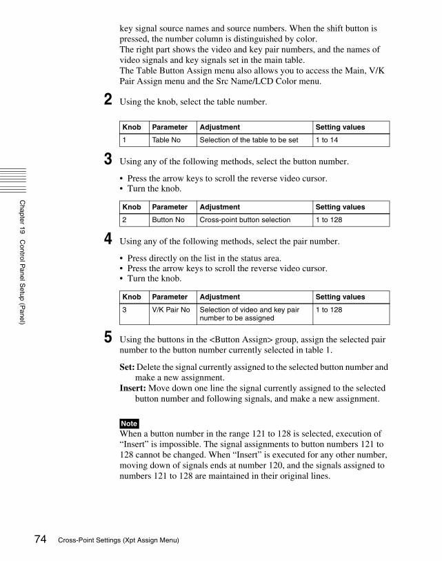
Chapter 19
Control P
anel Setup (P
anel)
74
key signal source names and source numbers. When the shift button is pressed, the number column is distinguished by color.The right part shows the video and key pair numbers, and the names of video signals and key signals set in the main table.The Table Button Assign menu also allows you to access the Main, V/K Pair Assign menu and the Src Name/LCD Color menu.
2 Using the knob, select the table number.
3 Using any of the following methods, select the button number.
• Press the arrow keys to scroll the reverse video cursor.• Turn the knob.
4 Using any of the following methods, select the pair number.
• Press directly on the list in the status area.• Press the arrow keys to scroll the reverse video cursor.• Turn the knob.
5 Using the buttons in the <Button Assign> group, assign the selected pair number to the button number currently selected in table 1.
Set: Delete the signal currently assigned to the selected button number and make a new assignment.
Insert: Move down one line the signal currently assigned to the selected button number and following signals, and make a new assignment.
Note When a button number in the range 121 to 128 is selected, execution of “Insert” is impossible. The signal assignments to button numbers 121 to 128 cannot be changed. When “Insert” is executed for any other number, moving down of signals ends at number 120, and the signals assigned to numbers 121 to 128 are maintained in their original lines.
Knob Parameter Adjustment Setting values
1 Table No Selection of the table to be set 1 to 14
Knob Parameter Adjustment Setting values
2 Button No Cross-point button selection 1 to 128
Knob Parameter Adjustment Setting values
3 V/K Pair No Selection of video and key pair number to be assigned
1 to 128
Cross-Point Settings (Xpt Assign Menu)

Chapter 19
Control P
anel Setup (P
anel)
To disable a buttonIn the Panel >Xpt Assign >Table Button Assign menu, select the button you want to disable, and press [Inhibit].To delete any currently assigned signalIn the Panel >Xpt Assign >Table Button Assign menu, select the button corresponding to the signal you want to delete, and press [Delete] in the <Button Assign> group.The signal assigned to the button number next to the selected button number and following signals move up one line.
Note When a button number in the range 121 to 128 is selected, execution of “Delete” is impossible. The signal assignments to button numbers 121 to 128 cannot be changed. When a signal assigned to any other button number is deleted, moving up of signals ends when the signal assigned to number 120 has moved to number 119, and the signals assigned to numbers 121 to 128 are maintained in their original lines.
Returning the table to its default state
1 In the Panel >Xpt Assign >Main, V/K Pair Assign menu or Panel >Xpt Assign >Table Button Assign menu, press [Default Recall].
A confirmation message appears, asking whether or not to return to the default state.
2 To return to the default state, press [Yes], and to cancel the operation, press [No].
Setting the cross-point button shift operationYou can set the operation of the rightmost button in each row of cross-point buttons excluding the reentry buttons.In the <Xpt Shift Mode> group of the Panel >Xpt Assign >Main, V/K Pair Assign menu or Panel >Xpt Assign >Table Button Assign menu, select one of the following for each cross-point table.Hold: Acts as a shift button, and the shifted version of the cross-point buttons
is enabled while the button is held down.Lock: Acts as a shift button, and pressing the button toggles between the
shifted version and the unshifted version.Off: Acts as a cross-point button, in a 16-button system as button number 16,
in a 24-button system as button number 24, and in a 32-button system as button number 32.
75Cross-Point Settings (Xpt Assign Menu)

Chapter 19
Control P
anel Setup (P
anel)
76
Setting the action of the [SHIFT] button in the cross-point control block
In the <Display Shift Mode> group of the Panel >Xpt Assign >Main, V/K Pair Assign menu or Panel >Xpt Assign >Table Button Assign menu, select either of the following.Display: Functions as a shift button dedicated to the source name displays.Shift All Bus: Functions as a shift button for all buses.
Notes• It is not possible to make this setting separately for each of the M/E and
PGM/PST banks.• “Shift All Bus” is only valid when the cross-point button shift operation (see
previous item) is set to “Lock” or “Off.”
Setting the source signal name
1 In the Panel >Xpt Assign menu or Panel >Xpt Assign >Table Button Assign menu, press [Src Name/LCD Color].
The Src Name/LCD Color menu appears.
2 Turn the knob to select the signal to be set.
3 Press [Source Name].
A keyboard window appears.
4 Enter any name of not more than 16 characters, then press [Enter].
For details of keyboard window operation, see “Menu Operations” in Chapter 2 (Volume 1).
Sequential names for multiple signalsWhen you specify a number at the end of a signal name, all of the signals in the range selected by knobs 1 and 2 are automatically assigned names ending with sequential numbers.Example: To assign sequential names to source signal 2 through source signal
41. In step 2 above, set knob 1 to “2,” and set knob 2 to “3.”2. Set the name of source signal 2 to “CAM2.”
Knob Parameter Adjustment Setting values
1 Source No Source signal selection 1 to 128
2 Num Number of source signals to be selected
1 to 128
Cross-Point Settings (Xpt Assign Menu)

Chapter 19
Control P
anel Setup (P
anel)
The name “CAM3” is assigned automatically to source signal 3, and the name “CAM4” is assigned automatically to source signal 4.Setting the source name display color
1 In the Panel >Xpt Assign >Table Button Assign >Src Name/LCD Color menu, turn the knobs to select the setting target.
2 In the <LCD Color> group, select the color (Orange/Green/Yellow).
Copying Cross-Point Assign Tables
The contents of a cross-point assign table can be copied to another cross-point assign table, and vice versa.
Note The contents of a sub table cannot be copied to the main table.
1 In the Panel >Xpt Assign menu, press [Table Copy].
The Table Copy menu appears.The status area shows a list of copy sources and a list of copy destinations.
2 Using any of the following methods, select the number of the table to use as the copy source and the number of the table you want to be the copy destination.
• Press directly on the list of copy sources (left-side list) or the list of copy destinations (right-side list) in the status area.
• Press the arrow keys to scroll the reverse video cursor.• Turn the knob.
3 Press [Copy].
Knob Parameter Adjustment Setting values
1 Source No Source signal selection 1 to 128
2 Num Number of source signals to be selected
1 to 128
Knob Parameter Adjustment Setting values
1 Left No Selection of copy source 1 to 15
2 Right No Selection of copy destination 1 to 14
77Cross-Point Settings (Xpt Assign Menu)

Chapter 19
Control P
anel Setup (P
anel)
78
A confirmation message appears, asking whether or not to execute the copy.
4 To execute the copy, press [Yes], and to cancel the operation, press [No].
Selecting Cross-Point Assign Tables
You can select the cross-point assign table to be used for each of the following banks or buses.• M/E-1 bank and PGM/PST bank• Buses assignable to AUX delegation buttons
NoteIt is not possible to assign cross-point tables 5 to 14 to a bus of a switcher operated by an MKS-8080/8082 AUX Bus Remote Panel.
1 In the Panel >Xpt Assign menu, using any of the following methods, select the switcher bank or bus.
• Press directly on the list on the left of the status area.• Press the arrow keys on the list on the left to scroll the reverse video
cursor.• Turn the knobs.
2 Using any of the following methods, select the table.
• Press directly on the list on the right of the status area.• Press the arrow keys on the list on the right to scroll the reverse video
cursor.• Turn the knob.
3 Press [Table Assign Set].
This sets the table for the selected switcher bank or bus.
Knob Parameter Adjustment Setting values
1 Bank/Bus No Switcher bank or bus selection
1 and upwards
2 Num Number of selected switcher banks or buses
1 and upwards
Knob Parameter Adjustment Values
3 Table No Selection of table to be assigned
1 to 15
Cross-Point Settings (Xpt Assign Menu)

Chapter 19
Control P
anel Setup (P
anel)
Exporting Source Names and Destination Names
To send the source names and destination names to the S-Bus, use the following procedure.
1 In the Panel >XPT Assign menu, press [Name Export].
The Name Export menu appears.
2 Turn the knob to set the station ID.
a) If set to 255, the information is sent to all stations (with display of “All”).
3 Press [Src Name Export].
This exports the source names to the station selected in step 2.
4 Press [Dest Name Export].
This exports the destination names to the station selected in step 2.
NoteSince destination names cannot be selected freely, fixed names are used.
Making Settings for Audio Mixer
Enabling the function to link the audio mixer
NoteFor audio mixer operations in this system, it is necessary to set Mixer ESAM-II for the DCU 9-pin serial port.
For details, see “Serial Port Settings (Serial Port Assign Menu)” (page 180).
1 In the Panel >Xpt Assign menu, using any of the following methods, select the M/E bank or bus.
• Press directly on the list on the left of the status area.• Press the arrow keys in the list on the left, to scroll the reverse video
cursor.• Turn the knob.
Knob Parameter Adjustment Setting values
1 Station ID Station ID setting 1 to 255 a)
79Cross-Point Settings (Xpt Assign Menu)

Chapter 19
Control P
anel Setup (P
anel)
80
2 Press [Audio Follow].
“Enable” appears in the Audio Follow column.
Setting the audio mixer cross-pointsTo assign an audio mixer cross-point to a switcher cross-point pair (video/key), carry out the following procedure.
1 In the Panel >Xpt Assign menu, press [Mixer Xpt Assign].
The Mixer Xpt Assign menu appears.
2 In the list on the left, select the number for the setting.
3 In the list on the right, select the audio mixer cross-point (machine number).
4 Press [Set].
The audio mixer number appears in the Mixer Xpt column.
Cross-Point Settings (Xpt Assign Menu)

Chapter 19
Control P
anel Setup (P
anel)
Auxiliary Bus Control Block Settings (Aux Assign Menu)
To carry out the settings of the AUX delegation buttons in the auxiliary bus control block, use the Panel >Aux Assign menu.
To display the Aux Assign menuIn the Engineering Setup menu, select VF2 ‘Panel’ and HF3 ‘Aux Assign.’The left side of the status area shows the delegation numbers, and the list of buses set; the right side shows a list of buses that can be assigned.
The following functions are available here.• Aux Assign: Assign the AUX delegation buttons in the auxiliary bus control
block to any bus.• Shift Mode: Specify whether the rightmost button of the AUX delegation
buttons is used as a shift button, and when it is used as a shift button, the operation mode.
Assigning a Bus to an AUX Delegation Button
1 In the Panel >Aux Assign menu, using any of the following methods, select the delegation button and the bus to be assigned.
• Press directly on the list in the status area.• Press the arrow keys to scroll the reverse video cursor.• Turn the knobs.
a) The setting can be from 1 to 20. The valid settings, however, depend on the number of buttons and the delegation button shift mode.
.
b) The buses that can be assigned are as follows.AUX1 to AUX48, Monitor1 to Monitor8, DME1V to DME4V, and DME1K to DME4K
Knob Parameter Adjustment Setting values
1 Deleg No Selection of AUX delegation button
1 to 128 a)
2 Bus No Selection of bus to be assigned 1 to 123 b)
Shift mode Valid settings
OFF 1 to 10
ON 1 to 20
81Auxiliary Bus Control Block Settings (Aux Assign Menu)

Chapter 19
Control P
anel Setup (P
anel)
82
M/E1 Utility1 and 2, P/P Utility1 and 2, Frame Memory Source1 and 2, Edit Preview, DSK1 to 4 Fill/Source, M/E-1 Key 1 to 4 Fill/Source, M/E-1 EXT DME, P/P EXT DME, DME Utility 1 and 2, and CCR 1 and 2
• For a button for which you want to disable operation, press [Inhibit].
2 Press [Set] to confirm the selection.
To set the AUX delegation button shift operationTo set the operation mode of the rightmost button in the row of AUX delegation buttons, select one of the following in the <Shift Mode> group of the Panel >Aux Assign menu.Hold: Acts as a shift button, and the shifted version of the AUX delegation
buttons is enabled while the button is held down.Lock: Acts as a shift button, and pressing the button toggles between the
shifted version and the unshifted version of the AUX delegation buttons.Off: Acts as an AUX delegation button. In a 16-button system it acts as button
number 16, in a 24-button system as button number 24, and in a 32-button system as button number 32.
Using the Auxiliary Bus Control Block for Router Control
To make router control settings, display the Setup >Panel >Aux Assign >RTR Mode Setting menu.This menu is used to make settings related to “Router Control Menu Operations” in Chapter 8 (Volume 1).
To display the RTR Mode Setting menu
1 In the Engineering Setup menu, select VF2 ‘Panel’ and HF3 ‘Aux Assign.’
The Aux Assign menu appears.
2 Press [RTR Mode Setting].
The RTR Mode Setting menu appears. The left of the status area shows the destination number assignment status and source table, and the right side lists the destinations that can be assigned.
Assigning a destination to a destination selection buttonIn the Panel >Aux Assign >RTR Mode Setting menu, use the following procedure.
Auxiliary Bus Control Block Settings (Aux Assign Menu)

Chapter 19
Control P
anel Setup (P
anel)
1 Using any of the following methods, select a destination selection buttonand the destination to be assigned to the button.
• Press directly on the list in the status area.• Press the arrow keys to scroll the reverse video cursor.• Turn the knobs.
• For a button whose operation you want to disable, press [Inhibit].
Note When a destination selection button having a number in the range 65 to 128 is selected, source table selection automatically becomes invalid, and therefore the Inhibit function also becomes invalid.
2 Press [Dest Set] to confirm the selection.
3 If in step 1 you selected a value in the range 1 to 64, turn the knob to select the source table.
4 Press [Source Table Set] to confirm the selection.
5 Repeat steps 1 to 4 as required.
To set the shift operation of the destination selection buttonsTo set the operation mode of the rightmost button in the destination selection button row, select one of the following in the <Dest Shift Mode> group of the Panel >Aux Assign >RTR Mode Setting menu.Hold: Acts as a shift button, and the shifted destination selection buttons are
enabled while the button is held down.Lock: Acts as a shift button, and pressing the button toggles between the
shifted and unshifted states of the destination selection buttons.Off: Acts as a destination selection button, that is, button number 16 on a 16-
button system, button number 24 on a 24-button system, and button number 32 on a 32-button system.
Knob Parameter Adjustment Setting values
1 Dest No Destination selection button selection
1 to 128
2 No Destination selection in S-Bus space
1 to 1024
Knob Parameter Adjustment Setting values
3 Source Table
Source table selection 1 to 5
83Auxiliary Bus Control Block Settings (Aux Assign Menu)

Chapter 19
Control P
anel Setup (P
anel)
84
Setting the source table
1 In the Panel >Aux Assign >RTR Mode Setting menu, press [Source Table Assign].
The Source Table Assign menu appears.
2 In the <Source Table Select> group, select the source table you want to manipulate.
3 Press [Table Assign].
The Table Assign menu appears.The left of the status area lists the button numbers and set sources, and the right side lists the source that can be assigned.
4 Using any of the following methods, select a source selection button and the source you want to assign.
• Press directly on the list in the status area.• Press the arrow keys to scroll the reverse video cursor.• Turn the knobs.
• For a button whose operation you want to disable, press [Inhibit].
5 Press [Source Set] to confirm the selection.
To set the shift operation of the source selection buttonsTo set the operation mode of the rightmost button in the source selection button row with different destinations assigned to the 1st and 2nd rows, select the source table in the Source Table Assign menu, then in the <Xpt Shift Mode> group select one of the following.Hold: Acts as a shift button, and the shifted source selection buttons are
enabled while the button is held down.Lock: Acts as a shift button, and pressing the button toggles between the
shifted and unshifted states of the source selection buttons.Off: Acts as a cross-point button, that is, button number 16 on a 16-button
system, button number 24 on a 24-button system, and button number 32 on a 32-button system.
Knob Parameter Adjustment Setting values
1 Source No Source selection button selection 1 to 128
2 No Source selection in S-Bus space 1 to 1024
Auxiliary Bus Control Block Settings (Aux Assign Menu)

Chapter 19
Control P
anel Setup (P
anel)
To expand the shift functionTo set the [KEY] button as a shift operation expansion button, in the Source Table Assign menu select the source table, then in the <Expand Xpt Shift Assign> group, press [Key Button].In order not to expand the shift operation, press [No Assign] in the <Expand Xpt Shift Assign> group.Assigning levels to a level selection buttonTo assign levels to the [LEVEL1] to [LEVEL4] buttons in the auxiliary bus control block, use the following procedure.
1 In the Panel >Aux Assign >RTR Mode Setting menu, press [Level Button Assign].
The Level Button Assign menu appears. The status area shows a list of the assignment status of levels to each button.
2 In the <Level Button Select> group, select the button you want to set.
3 In the <Level Assign> group, press the levels you want to assign to the button, turning them on.
You can select plural of levels. You can also make a selection that overlaps that of another button.
Selecting a destination selection button for a snapshotTo set whether snapshots are recalled for each destination selection button individually, use the Panel >Aux Assign >RTR Mode Setting menu as follows.
1 Use any of the following methods to select the destination selection button to which the setting applies.
• Press directly on the list on the left of the status area.• Press the arrow keys to scroll the reverse video cursor.• Turn the knob.
2 Press [SS Enable], turning it on or off.
On: When a snapshot applying to the router is recalled, the recall also applies to the selected destination selection button.
Off: When a snapshot applying to the router is recalled, the recall does not apply to the selected destination selection button.
Knob Parameter Adjustment Setting values
1 Dest No Selection of destination selection button
1 to 128
85Auxiliary Bus Control Block Settings (Aux Assign Menu)

Chapter 19
Control P
anel Setup (P
anel)
86
NoteWhen a destination selection button is set to Inhibit, then even if SS Enable is on, the snapshot for that destination is not recalled.
Auxiliary Bus Control Block Settings (Aux Assign Menu)

Chapter 19
Control P
anel Setup (P
anel)
Setting Button Assignments (Prefs/Utility Menu)
Assign the [PREFS 1] to [PREFS 16] buttons in the menu control block, and the utility/shotbox control block buttons.This assigns recalling frequently used menus (menu shortcuts), enabling/disabling functions (recalling utility commands) and recalling shotbox registers or macro registers.• User Preference: Make the settings for the user preference buttons in the
menu control block. • Utility Module Assign: Make the utility/shotbox control block settings.
To display the Prefs/Utility menuIn the Engineering Setup menu, select VF2 ‘Panel’ and HF4 ‘Prefs/Utility.’The status area shows the settings of the user preference buttons.
Assigning Functions to User Preference Buttons
1 In the Panel >Prefs/Utility menu, using any of the following methods, select the button to be assigned.
• Press directly on the list in the status area.• Press the arrow keys to scroll the reverse video cursor.• Turn the knob.
2 In the <Action> group, select the function to be assigned.
Menu Shortcut: Assign a frequently used menu to be recalled (menu shortcut).
Utility Command: Assign a function enable/disable or similar operation (utility command).
Macro Recall: Assign a macro register recall.Shotbox Recall: Assign a shotbox register recall.
3 Depending on the selection in step 2, make the following settings.
Knob Parameter Adjustment Setting values
1 No User preference button selection 1 to 16
87Setting Button Assignments (Prefs/Utility Menu)

Chapter 19
Control P
anel Setup (P
anel)
88
When Menu Shortcut is selected: For the subsequent operations, see the next item “Assigning a menu shortcut to a user preference button” (page 91).
When Utility Command is selected: A list of commands appears on the right of the status area; using any of the following methods, select the command you want to assign.• Press directly on the list.• Press the arrow keys to scroll the reverse video cursor.• Turn the knob.
a) When the Command parameter is set to Sw’er GPI Test Fire, Panel GPI Test Fire, DCU GPI, or Test Fire
When Macro Recall is selected: Turn the knob to select the macro register you want to assign.
When Shotbox Recall is selected: Turn the knob to select the shotbox register you want to assign.
4 Press [Action Set].
This assigns the selected action, which is reflected in the status area.
To cancel an assignmentAfter selecting the relevant button, press [Clear].
Using the [PREFS 9] to [PREFS 16] settingsThere are sixteen user preference buttons that can be set, [PREFS 1] to [PREFS 16], but there are only eight user preference buttons present in the menu control block. By default these buttons are assigned to the [PREFS 1] to [PREFS 8] settings. Therefore, to use the settings of [PREFS 9] to [PREFS 16], it is necessary to access the Engineering Setup >Panel >Config >Link/Program Button >Menu Panel menu, and assign these settings to buttons in the menu control block.
Knob Parameter Adjustment Setting values
3 Command Utility command selection 1 and upwards
4 a) GPI No GPI port number 1 and upwards
Knob Parameter Adjustment Setting values
3 Macro Macro register selection 1 to 99
Knob Parameter Adjustment Setting values
3 Shotbox Shotbox register selection 1 to 99
Setting Button Assignments (Prefs/Utility Menu)

Chapter 19
Control P
anel Setup (P
anel)
List of utility commands and user preference button statusThe following table shows the utility commands that can be assigned to user preference buttons.
Command name a) Function Button status
Lit amber Off
SWR Remote1 Enbl|
SWR Remote4 Enbl
Switcher Remote 1 enabled/disabled|
Switcher Remote 4 enabled/disabled
Enabled Disabled
DME1 Editor Port Enbl DME1 editor port enabled/disabled Enabled Disabled
DME2 Editor Port Enbl DME2 editor port enabled/disabled Enabled Disabled
2nd System Enbl (Dual Simul Mode) Second system enabled/disabled
Enabled Disabled
ME1 PGM1 ST|
ME1 PGM4 ST
M/E-1 PGM1 output safe title on/off|
M/E-1 PGM4 output safe title on/off
On Off
ME1 PVW ST M/E-1 preview output safe title on/off On Off
ME1 Clean ST M/E-1 clean output safe title on/off On Off
ME1 K-PVW ST M/E-1 key preview output safe title on/off
On Off
ME2 PGM1 ST|
ME2 PGM4 ST
M/E-2 PGM1 output safe title on/off|
M/E-2 PGM4 output safe title on/off
On Off
ME2 PVW ST M/E-2 preview output safe title on/off On Off
ME2 Clean ST M/E-2 clean output safe title on/off On Off
ME2 K-PVW ST M/E-2 key preview output safe title on/off
On Off
ME3 PGM1 ST|
ME3 PGM4 ST
M/E-3 PGM1 output safe title on/off|
M/E-3 PGM4 output safe title on/off
On Off
ME3 PVW ST M/E-3 preview output safe title on/off On Off
ME3 Clean ST M/E-3 clean output safe title on/off On Off
ME3 K-PVW ST ME-3 key preview output safe title on/off
On Off
PP PGM1 ST|
PP PGM4 ST
P/P PGM1 output safe title on/off|
P/P PGM4 output safe title on/off
On Off
PP PVW ST P/P preview output safe title on/off On Off
PP Clean ST P/P clean output safe title on/off On Off
PP K-PVW ST P/P key preview output safe title on/off On Off
DME MON1 ST DME Monitor 1 output safe title on/off On Off
DME MON2 ST DME Monitor 2 output safe title on/off On Off
Edit PVW ST Edit preview output safe title on/off On Off
89Setting Button Assignments (Prefs/Utility Menu)

Chapter 19
Control P
anel Setup (P
anel)
90
Preset ST Preset output safe title on/off On Off
AUX1 ST|
AUX48 ST
AUX1 output safe title on/off|
AUX48 output safe title on/off
On Off
FM Src1 Frame Freeze
Frame freeze of frame memory source 1
During frame freeze
Either of the other two states
FM Src1 Filed Freeze Field freeze of frame memory source 1 During field freeze
Either of the other two states
FM Src1 Freeze Off Release freeze of frame memory source 1
While freeze being released
Either of the other two states
FM Src2 Frame Freeze
Frame freeze of frame memory source 2
During frame freeze
Either of the other two states
FM Src2 Field Freeze Field freeze of frame memory source 2 During field freeze
Either of the other two states
FM Src2 Freeze Off Release freeze of frame memory source 2
While freeze being released
Either of the other two states
SWR GPI Enbl Enable/disable switcher GPI Enabled Disabled
DME1 GPI Enbl Enable/disable DME1 GPI Enabled Disabled
DME2 GPI Enbl Enable/disable DME2 GPI Enabled Disabled
Panel GPI Enbl Enable/disable panel GPI Enabled Disabled
SWR GPI1 Test Fire |
SWR GPI8 Test Fire
Output test trigger from switcher GPI1 |
Output test trigger from switcher GPI8
Output (lights only at the instant the button is pressed)
When the output is assigned
Panel GPI1 Test Fire |
Panel GPI8 Test Fire
Output test trigger from panel GPI1 |
Output test trigger from panel GPI8
Output (lights only at the instant the button is pressed)
When the output is assigned
DCU GPI1 Test Fire |
DCU GPI50 Test Fire
Output test trigger from port assigned to DCU GPI1
|Output test trigger from port assigned to DCU GPI50
Output (lights only at the instant the button is pressed)
When the output is assigned
Macro Attachment Enbl
Enable/disable macro attachment Enabled Disabled
Macro Only Set Macro only mode on/off On Off
Pre Macro Set macro attachment in pre macro mode
Can be set only while pressed (lit)
When the function is assigned
Post Macro Set macro attachment in post macro mode
Can be set only while pressed (lit)
When the function is assigned
Macro Take Macro execution During execution When the function is assigned
Macro Auto Ins Macro auto insert mode on/off On Off
Command name a) Function Button status
Lit amber Off
Setting Button Assignments (Prefs/Utility Menu)

Chapter 19
Control P
anel Setup (P
anel)
a) For the safe title on/off commands (from ME1 PGM1 ST-ME1 PGM4 ST to AUX1 ST-AUX48 ST), the name of the assigned output signal is shown.
Assigning a menu shortcut to a user preference button
1 Referring to the procedure up to step 2 on page 87, select [Menu Shortcut].
The user preference buttons [PREFS 1] to [PREFS 16] flash amber.
2 Using any of the following methods, display the menu to which you want to make a shortcut.
• In the menu control block, press the relevant top menu selection button, then select VF and HF.
• Press the menu page number button in the upper left corner of the menu screen, then enter a menu number from the numeric keypad window.
• Press a particular control panel button twice in rapid succession.
3 Press the user preference button to which you want to assign the shortcut.
The menu screen goes back to the Prefs/Utility menu, and the selection is reflected in the status area. The user preference buttons [PREFS 1] to [PREFS 16] flash amber.
Macro AT with Rate When registering an auto transition macro event, on/off setting of mode to save transition rate
On Off
Macro AT with A/B Bus When registering an auto transition macro event for the transition control block, on/off setting of mode to save A/B Bus cross-point settings
On Off
Macro TL with Region When registering a timeline macro event, on/off setting of mode to save applicable region
On Off
DME Override DME override on/off On Off
DME Graphic DME graphics on/off (Applies to graphics for channel selected in device control block)
On Off
System Manager Enbl Enable/disable operation from System Manager
Enabled Disabled
Plug-In Editor Enbl Enable/disable operation from an editing keyboard
Enabled Disabled
Inhibit Set Inhibit cross-point button Can be set only while pressed (lit)
When the function is assigned
Inhibit All Clear Clear all cross-point button inhibit settings
Can be set only while pressed (lit)
When the function is assigned
Command name a) Function Button status
Lit amber Off
91Setting Button Assignments (Prefs/Utility Menu)

Chapter 19
Control P
anel Setup (P
anel)
92
4 Repeat steps 2 and 3 as required, to assign all desired menu shortcuts to the user preference buttons.
To abandon the process of menu shortcut assignmentIn the Prefs/Utility menu, press [Menu Shortcut] once more.This exits the menu shortcut assignment mode.
Assigning a Function to a Memory Recall Button in the Utility/Shotbox Control Block (MKS-8033 Utility/Shotbox Module, Option)
1 In the Prefs/Utility menu, press [Utility Module Assign].
The Prefs/Utility >Utility Module Assign menu appears. The status area shows the settings in the utility/shotbox control block.
2 Using any of the following methods, select the button to be assigned.
• Press directly on the list.• Press the arrow keys to scroll the reverse video cursor.• Turn the knobs.
3 In the <Action> group, select the function you want to assign.
Menu Shortcut: Assign a frequently used menu to be recalled (menu shortcut).
Utility Command: Assign a function enable/disable or similar operation (utility command).
Macro Recall: Assign a macro register recall.Shotbox Recall: Assign a shotbox register recall.
4 Depending on the selection in step 3, make the following settings.
When Menu Shortcut is selected: For the subsequent operations, see the next item “Assigning a menu shortcut to a memory recall button” (page 96).
When Utility Command is selected: A list of commands appears on the right of the status area; using any of the following methods, select the command you want to assign.• Press directly on the list.
Knob Parameter Adjustment Setting values
1 Bank Bank selection 1 to 4
2 Button No Control block button selection 1 to 24
Setting Button Assignments (Prefs/Utility Menu)

Chapter 19
Control P
anel Setup (P
anel)
• Press the arrow keys to scroll the reverse video cursor.• Turn the knob.a) When the Command parameter is set to Sw’er GPI Test Fire, Panel GPI Test Fire, DCU GPI, or Test Fire
When Macro Recall is selected: Turn the knob to select the macro register you want to assign.
When Shotbox Recall is selected: Turn the knob to select the shotbox register you want to assign.
5 Press [Action Set].
This assigns the selected action, which is reflected in the status area.In the utility/shotbox control block, the assigned button lights orange.If a shotbox register was assigned, the register name appears.
To cancel an assignmentAfter selecting the relevant button, press [Clear].
List of utility commands and memory recall button statusThe following table shows the utility commands that can be assigned to memory recall buttons.
Knob Parameter Adjustment Setting values
3 Command Utility command selection 1 and upwards
4 a) GPI No GPI port number 1 and upwards
Knob Parameter Adjustment Setting values
3 Macro Macro register selection 1 to 99
Knob Parameter Adjustment Setting values
3 Shotbox Shotbox register selection 1 to 99
Command name a) Function Button status
Lit green Lit orange
SWR Remote1 Enbl|
SWR Remote4 Enbl
Switcher Remote 1 enabled/disabled|
Switcher Remote 4 enabled/disabled
Enabled Disabled
DME1 Editor Port Enbl DME1 editor port enabled/disabled Enabled Disabled
DME2 Editor Port Enbl DME2 editor port enabled/disabled Enabled Disabled
2nd System Enbl (Dual Simul Mode) Second system enabled/disabled
Enabled Disabled
93Setting Button Assignments (Prefs/Utility Menu)

Chapter 19
Control P
anel Setup (P
anel)
94
ME1 PGM1 ST|
ME1 PGM4 ST
M/E-1 PGM1 output safe title on/off|
M/E-1 PGM4 output safe title on/off
On Off
ME1 PVW ST M/E-1 preview output safe title on/off On Off
ME1 Clean ST M/E-1 clean output safe title on/off On Off
ME1 K-PVW ST M/E-1 key preview output safe title on/off
On Off
ME2 PGM1 ST|
ME2 PGM4 ST
M/E-2 PGM1 output safe title on/off|
M/E-2 PGM4 output safe title on/off
On Off
ME2 PVW ST M/E-2 preview output safe title on/off On Off
ME2 Clean ST M/E-2 clean output safe title on/off On Off
ME2 K-PVW ST M/E-2 key preview output safe title on/off
On Off
ME3 PGM1 ST|
ME3 PGM4 ST
M/E-3 PGM1 output safe title on/off|
M/E-3 PGM4 output safe title on/off
On Off
ME3 PVW ST M/E-3 preview output safe title on/off On Off
ME3 Clean ST M/E-3 clean output safe title on/off On Off
ME3 K-PVW ST ME-3 key preview output safe title on/off
On Off
PP PGM1 ST|
PP PGM4 ST
PP PGM1 output safe title on/off|
PP PGM4 output safe title on/off
On Off
PP PVW ST P/P preview output safe title on/off On Off
PP Clean ST P/P clean output safe title on/off On Off
PP K-PVW ST P/P key preview output safe title on/off On Off
DME MON1 ST DME Monitor 1 output safe title on/off On Off
DME MON2 ST DME Monitor 2 output safe title on/off On Off
Edit PVW ST Edit preview output safe title on/off On Off
Preset ST Preset output safe title on/off On Off
AUX1 ST|
AUX48 ST
AUX1 output safe title on/off|
AUX48 output safe title on/off
On Off
FM Src1 Frame Freeze
Frame freeze of frame memory source 1
During frame freeze
Either of the other two states
FM Src1 Filed Freeze Field freeze of frame memory source 1 During field freeze
Either of the other two states
FM Src1 Freeze Off Release freeze of frame memory source 1
While freeze being released
Either of the other two states
Command name a) Function Button status
Lit green Lit orange
Setting Button Assignments (Prefs/Utility Menu)

Chapter 19
Control P
anel Setup (P
anel)
FM Src2 Frame Freeze
Frame freeze of frame memory source 2
During frame freeze
Either of the other two states
FM Src2 Field Freeze Field freeze of frame memory source 2 During field freeze
Either of the other two states
FM Src2 Freeze Off Release freeze of frame memory source 2
While freeze being released
Either of the other two states
SWR GPI Enbl Enable/disable switcher GPI Enabled Disabled
DME1 GPI Enbl Enable/disable DME1 GPI Enabled Disabled
DME2 GPI Enbl Enable/disable DME2 GPI Enabled Disabled
Panel GPI Enbl Enable/disable panel GPI Enabled Disabled
SWR GPI1 Test Fire|
SWR GPI8 Test Fire
Output test trigger from switcher GPI1|
Output test trigger from switcher GPI8
Output (lights only at the instant the button is pressed)
When the output is assigned
Panel GPI1 Test Fire |
Panel GPI8 Test Fire
Output test trigger from panel GPI1 |
Output test trigger from panel GPI8
Output (lights only at the instant the button is pressed)
When the output is assigned
DCU GPI1 Test Fire|
DCU GPI50 Test Fire
Output test trigger from port assigned to DCU GPI1
|Output test trigger from port assigned to DCU GPI50
Output (lights only at the instant the button is pressed)
When the output is assigned
Macro Attachment Enbl
Enable/disable macro attachment Enabled Disabled
Macro Only Set Macro only mode on/off On Off
Pre Macro Set macro attachment in pre macro mode
Can be set only while pressed (lit)
When the function is assigned
Post Macro Set macro attachment in post macro mode
Can be set only while pressed (lit)
When the function is assigned
Macro Take Macro execution During execution When the function is assigned
Macro Auto Ins Macro auto insert mode on/off On Off
Macro AT with Rate When registering an auto transition macro event, on/off setting of mode to save transition rate
On Off
Macro AT with A/B Bus When registering an auto transition macro event for the transition control block, on/off setting of mode to save A/B Bus cross-point settings
On Off
Macro TL with Region When registering a timeline macro event, on/off setting of mode to save applicable region
On Off
DME Override DME override on/off On Off
Command name a) Function Button status
Lit green Lit orange
95Setting Button Assignments (Prefs/Utility Menu)

Chapter 19
Control P
anel Setup (P
anel)
96
a) For the safe title on/off commands (from ME1 PGM1 ST-ME1 PGM4 ST to AUX1 ST-AUX48 ST), the name of the assigned output signal is shown.
Assigning a menu shortcut to a memory recall button
1 Referring to the procedure up to step 3 on “Assigning a Function to a Memory Recall Button in the Utility/Shotbox Control Block (MKS-8033 Utility/Shotbox Module, Option)” (page 92), select [Menu Shortcut].
The memory recall buttons in the utility/shotbox control block flash orange.
2 Using any of the following methods, display the menu to which you want to make a shortcut.
• In the menu control block, press the relevant top menu selection button, then select VF and HF.
• Press the menu page number button in the upper left corner of the menu screen, then enter a menu number from the numeric keypad window.
• Press a particular control panel button twice in rapid succession.
3 In the utility/shotbox control block, select the bank, and press the button to which you want to assign the shortcut.
The menu screen goes back to the Prefs/Utility >Utility Module Assign menu, and the selection is reflected in the status area.The buttons in the utility/shotbox control block flash.
4 Repeat steps 2 and 3 as required, to assign all desired menu shortcuts to the buttons in the utility/shotbox control block.
To abandon the process of menu shortcut assignmentIn the Prefs/Utility >Utility Module Assign menu, press [Menu Shortcut].This exits the menu shortcut assignment mode.
DME Graphic DME graphics on/off (Applies to graphics for channel selected in device control block)
On Off
Plug-In Editor Enbl Enable/disable operation from an editing keyboard
Enabled Disabled
Inhibit Set Inhibit cross-point button Can be set only while pressed (lit)
When the function is assigned
Inhibit All Clear Clear all cross-point button inhibit settings
Can be set only while pressed (lit)
When the function is assigned
Command name a) Function Button status
Lit green Lit orange
Setting Button Assignments (Prefs/Utility Menu)

Chapter 19
Control P
anel Setup (P
anel)
Setting names to be displayed in memory recall buttonsNoteThe name you set using the following procedure is displayed only when “Menu Shortcut” or “Utility Command” has been assigned to the selected memory recall button. To set a name for display in a memory recall button to which “Shotbox Recall” or “Macro Recall” has been assigned, use the Shotbox menu or Macro menu.
1 In the Prefs/Utility >Utility Module Assign menu, select the button using any of the following methods.
• Press directly on the list.• Press the arrow keys to scroll the reverse video cursor.• Turn the knobs.
2 Press [Name].
A keyboard window appears.
3 Enter a name of not more than eight characters, and press [Enter].
The name you have set is reflected in the status area and on the memory recall button in the utility/shotbox control block.
Knob Parameter Adjustment Setting values
1 Bank Bank selection 1 to 4
2 Button No Control block button selection 1 to 24
97Setting Button Assignments (Prefs/Utility Menu)

Chapter 19
Control P
anel Setup (P
anel)
98
Interfacing With External Devices (Device Interface Menu)
To carry out setup relating to connections with external devices, display the Panel >Device Interface menu.
To display the Device Interface menuIn the Engineering Setup menu, select VF2 ‘Panel’ and HF5 ‘Device Interface.’
The following functions are available here.• GPI Input: Set the GPI input ports and trigger type, and make the action
settings.• GPI Output: Set the GPI output ports and trigger type, and make the action
settings.• P-Bus Control: Set the control mode for P-Bus devices.• DCU Serial Port Assign: Assign the devices (disk recorder/VTR/Extended
VTR) connected to a DCU and accessible from the control panel to the [DEV1] to [DEV12] buttons which become operative when you press the [DEV] button on the device control block. For a disk recorder or Extended VTR, you can also make settings relating to sharing of file lists. Further, you can make settings for devices (disk recorder/VTR/Extended VTR) operable from an editing keyboard.
• Editor Port Assign: When the BZS-8050 license is valid, make settings for the SCU editor panel port.
Making Control Panel GPI Input Settings
1 In the Panel >Device Interface menu, press [GPI Input].
The GPI Input menu appears.
2 Using any of the following methods, select the settings.
• Press directly on the list in the status area.• Press the arrow keys to scroll the reverse video cursor.• Turn the knob.
Knob Parameter Adjustment Setting values
1 Port Port selection 1 to 8
Interfacing With External Devices (Device Interface Menu)

Chapter 19
Control P
anel Setup (P
anel)
3 In the <Trigger Type> group, select the trigger type.(Rising Edge): Apply the trigger on a rising edge of an input pulse.
(Falling Edge): Apply the trigger on a falling edge of an input pulse.
(Any Edge): Apply the trigger on a change in the polarity of the input signal.
(Level): Carry out the specified operation when the input is low or high.
No Operation: Apply no trigger on an input pulse.
4 In the <Target> group, select the action block.
M/E-1, M/E-2, M/E-3, P/P: Set the action for one of the banks.Common/Setup: Set an action for something other than the above, or a
setup action.
5 Using any of the following methods, select the action to be set.
• Press directly on the list in the status area.• Press the arrow keys to scroll the reverse video cursor.• Turn the knobs.
a) As for the setting values, see “Selectable actions for various trigger types” (page 99).b) When knob 2 selection is “Aux ? O’ride Src ??”c) When knob 2 selection is “Key Snapshot”d) When knob 2 selection is “Snapshot” or “Shotbox”e) When knob 2 selection is “Effect”f) When knob 2 selection is “Prefs Button?”
6 Press [Action Set] to confirm the action selection.
The selected setting appears in the status area.
Selectable actions for various trigger types• When the trigger type is other than “Level”
Knob Parameter Adjustment Setting values
2 Action Action selection 1 and upwards a)
4 Aux Bus No Aux bus selection 1 to 48 b)
5 Reg No Register number 1 to 4 c)
1 to 99 d)
1 to 399 e)
5 Src No Source signal selection 1 and upwards b)
5 No User preference button selection
1 to 16 f)
99Interfacing With External Devices (Device Interface Menu)

Chapter 19
Control P
anel Setup (P
anel)
100
When Target is M/E-1, M/E-2, or M/E-3: Cut, Auto TransKey1 Cut, Key2 Cut, Key3 Cut, Key4 CutKey1 Auto Trans, Key2 Auto Trans, Key3 Auto Trans, Key4 Auto TransKey1 SS ? Recall, Key2 SS ? Recall, Key3 SS ? Recall, Key4 SS ? Recall
When Target is P/P: Cut, Auto TransDSK1 Cut, DSK2 Cut, DSK3 Cut, DSK4 CutDSK1 Auto Trans, DSK2 Auto Trans, DSK3 Auto Trans, DSK4 Auto TransDSK1 SS ? Recall, DSK2 SS ? Recall, DSK3 SS ? Recall, DSK4 SS ? Recall FTB Cut, FTB Auto Trans
When Target is Common/Setup: Master SS ? Recall, Master Effect ? Recall, SS ? Recall, Effect ? Recall, Effect ? Recall & Run, KF Run, KF Stop, KF Rewind, FM Src1 Frame Freeze, FM Src1 Field Freeze, FM Src1 Freeze Off, FM Src2 Frame Freeze, FM Src2 Field Freeze, FM Src2 Freeze Off, FM Src1 Clip Record, FM Src1 Clip Stop, FM Src2 Clip Record, FM Src2 Clip Stop, FM1 to FM8 Clip Cueup, FM1 to FM8 Clip Play, FM1 to FM8 Clip Stop, Shotbox ? Recall, Macro Take, Prefs Buttons?, Macro ? Recall, No Action
• When the trigger type is only “Rising Edge” or “Falling Edge”Aux? O’ride Src??
• When the trigger type is “Level”When Target is M/E-1, M/E-2, M/E-3, or P/P: No ActionWhen Target is Common/Setup: Format (Overall system settings, frame/
field rate, number of lines)Aspect (overall system settings), Simul, Level Enable, No Action
Notes• “Level Enable” is a function that determines whether GPI inputs are enabled
(“Enable”) or disabled (“Disable”) for the “Aspect” and “Format” actions that can be used when the trigger type is Level. When Level Enable is used, if the input is “Disable” then it is not possible to switch “Aspect” or “Format” by GPI input.If a GPI to switch “Aspect” or “Format” occurs when powering the system off, the action triggered by the GPI may start immediately before the power goes off and the power may go off before the action is completed. This may corrupt the setup settings. It is therefore recommended to use Level Enable to avoid such a situation.
• As for “Aux ? O’ride Src ??,” when “Rising Edge” is selected, on a rising edge the set AUX bus primary input is used. On a falling edge, the original state of the cross-point is restored. If the GPI trigger is applied repeatedly at short intervals (0.5 second or less), the cross-point switching may not be carried out correctly. In this case, apply the GPI trigger again.
Interfacing With External Devices (Device Interface Menu)

Chapter 19
Control P
anel Setup (P
anel)
Carrying out level settingsTo set the low level and high level, first set the trigger type to “Level,” then use the following procedure.
1 In the Panel >Device Interface menu, select the action to be set, and press [H/L Set].
The H/L Set menu appears.
2 Using any of the following methods, select the settings.
• Press directly on the list in the status area.• Press the arrow keys to scroll the reverse video cursor.• Turn the knob.
3 To apply the selection made in step 2 when the input is the GPI high level, press [H Set]. To apply the selection made in step 2 when the input is low, press [L Set].
This confirms the setting, which appears in the status area.
Making Control Panel GPI Output Settings
1 In the Panel >Device Interface menu, press [GPI Output].
The GPI Output menu appears.
2 Using any of the following methods, select the settings.
• Press directly on the list in the status area.• Press the arrow keys to scroll the reverse video cursor.• Turn the knob.
3 In the <Trigger Type> group, select the trigger polarity.
(Rising Edge): The trigger causes the relay contacts to be open-circuit or drives the output high, and holds this state for the specified pulse width.
Knob Parameter Adjustment Setting values
1 No Signal format/screen aspect ratio selection
1 and upwards
Knob Parameter Adjustment Setting values
1 Port Port selection 1 to 8
101Interfacing With External Devices (Device Interface Menu)

Chapter 19
Control P
anel Setup (P
anel)
102
(Falling Edge): The trigger causes the relay contacts to be shorted or drives the output low, and holds this state for the specified pulse width.
(Any Edge): Each time the trigger occurs, the relay contacts are alternately closed or opened, or the output is switched between high and low.
Status: Depending on the status, the relay contacts are closed or opened, or the output is switched between high and low.
No Operation: The trigger has no effect on the relay state or output level.
4 Turning the knobs, select the pulse width and timing to be set.
a) 1: Field 1, 2: Field 2, 3: Any
When “ ” is selected as the trigger polarity, there is no Pulse Width setting. When “Status” is selected, there is no Pulse Width or Timing setting.
5 In the <Source> group, select the action block.
M/E-1 to M/E-3 and P/P: Set an action for the M/E or PGM/PST bank.Common: Set an action for error status.
6 Using any of the following methods, select the action to be set.
• Press directly on the list in the status area.• Press the arrow keys to scroll the reverse video cursor.• Turn the knobs.
a) • Action list when the trigger type is other than “Status”When Source is M/E-1, M/E-2, or M/E-3: Key1 SS ? Recall, Key2 SS ? Recall, Key3
SS ? Recall, Key4 SS ? Recall, No ActionWhen Source is P/P: DSK1 SS ? Recall, DSK2 SS ? Recall, DSK3 SS ? Recall, DSK
4 SS ? Recall, No ActionWhen Source is Common: KF Run, No Action
• Action list when the trigger type is “Status”When Source is M/E-1, M/E-2, or M/E-3: Key1 SS ? Recall, Key2 SS ? Recall, Key3
SS ? Recall, Key4 SS ? RecallKey1 On, Key2 On, Key3 On, Key4 On, No Action
Knob Parameter Adjustment Setting values
3 Pulse Width Pulse width 1 to 60 (fields)
4 Timing Output timing 1 to 3 a)
Knob Parameter Adjustment Setting values
2 Action Action selection 1 and upwards a)
5 Reg No Register number 1 to 4 b)
Interfacing With External Devices (Device Interface Menu)

Chapter 19
Control P
anel Setup (P
anel)
When Source is P/P: DSK1 SS ? Recall, DSK2 SS ? Recall, DSK3 SS ? Recall, DSK4SS ? RecallDSK1 On, DSK2 On, DSK3 On, DSK4 On, No Action
When Source is Common: Error Make, Error Break, PREFS1, PREFS2, PREFS3, PREFS4, PREFS5, PREFS6, PREFS7, PREFS8, PREFS9, PREFS10, PREFS11, PREFS12, PREFS13, PREFS14, PREFS15, PREFS16, Device Recording, No Action
b) When knob 2 selection is “Key Snapshot”
7 Press [Action Set] to confirm the action selection.
The selected setting appears in the status area.
Test firing the triggerTo test fire the trigger, press [Test Fire].This outputs a trigger from the selected output port. This is not output when the trigger type is “Status.”
Setting the Control Mode for P-Bus Devices
In the <P-Bus Control> group of the Panel >Device Interface menu, select the mode.Trigger: When a predetermined button is pressed, the action command
assigned to that button is output, to control an external device.Timeline: The external device is controlled as a keyframe effect controlled by
the center control panel.
Setting the SCU Editor Panel Port
When an editing keyboard is used, this port setting is for the editing keyboard if the license for the BZS-8050 is valid (see page 28), and for the serial tally if the license for the BZS-8050 is invalid.If you want to use the port setting for the serial tally when the license for the BZS-8050 is valid, select [Serial Tally] from the <Editor Port Assign> group in the Panel >Device Interface menu.Serial Tally: Use the SCU editor panel port for the serial tally.Editor Keyboard: Use the SCU editor panel port for the editing keyboard.
103Interfacing With External Devices (Device Interface Menu)

Chapter 19
Control P
anel Setup (P
anel)
104
Making DCU Serial Port Settings
You can assign buttons in the device control block (DEV1 to DEV12) to DCU serial ports, to operate the devices (disk recorder/VTR/Extended VTR) connected to these ports. For a disk recorder/Extended VTR, you can also set the sharing of file lists.
For details of DCU serial port settings, see “Serial Port Settings (Serial Port Assign Menu)” (page 180).
Associating a serial port with a device selection button
1 In the Panel >Device Interface menu, press [DCU Serial Port Assign].
The Serial Port Assign menu appears.
2 Using any of the following methods, select the DCU serial port.
• Press directly on the list in the status area.• Press the arrow keys to scroll the reverse video cursor.• Turn the knob.
a) The range of the setting value depends on the DCU port settings.
The DCU number, slot number, and serial port number appear.
3 Select the device selection button to be assigned from the <Assign> group.
Notes• It is not possible to assign more than one device selection button to the
same port. The later assigned device selection button takes priority, and the previous selection is invalidated.
• If P-Bus/Mixer ESAM-II is assigned to a serial port, it is not possible to assign a device selection button to that port.
4 Repeat steps 2 and 3 as required to make assignments to other ports.
To select whether to use an editing keyboardIf you want to use an editing keyboard for the selected device, select a port using the same operation as in step 2, then press [Plug-In Editor Enbl] to display “Enbl” in the Editor column. If you do not want to use an editing keyboard, press [Plug-In Editor Enbl] to make the “Enbl” display disappear.
Knob Parameter Adjustment Setting values
1 No Serial port selection 1 and upwards a)
Interfacing With External Devices (Device Interface Menu)

Chapter 19
Control P
anel Setup (P
anel)
Notes • This selection is possible when the BZS-8050 license is valid (see page 28).• A port to which Mixer ESAM-II is assigned is automatically set to Enbl, and
you cannot change this setting.
Sharing Disk Recorder/Extended VTR File Lists
To share files between devices connected to the same disk recorder/Extended VTR, use the following procedure.
Note The following operation can only be carried out for the ports to which a disk recorder or Extended VTR is assigned.
1 In the Panel >Device Interface >Serial Port Assign menu, select the target disk recorder/Extended VTR.
• Press directly on the list in the status area.• Press the arrow keys to scroll the reverse video cursor.• Turn the knob.
a) The range of the setting value depends on the DCU port settings.
2 Turn the knob to select the device selection button (DEV1 to DEV12) for sharing the file list.
3 Press [Same File List Set].
This is reflected in the file list in the status area.
4 Repeat steps 1 to 3 as required to select other devices for sharing the file list.
Knob Parameter Adjustment Setting values
1 No Serial port selection 1 and upwards a)
Knob Parameter Adjustment Setting values
2 File List Device selection button for sharing the file list
1 to 12
105Interfacing With External Devices (Device Interface Menu)

Chapter 19
Control P
anel Setup (P
anel)
106
Operation Settings (Operation Menu)
To make settings relating to panel operation, use the Panel >Operation menu.
To display the Operation menuIn the Engineering Setup menu, select VF2 ‘Panel’ and HF6 ‘Operation.’The status area shows the items that can be set and a list of the settings.
The following functions are available here.• Button Tally: Set whether or not the system tally generation results are
reflected in the panel tally.• Trans Rate Display: Select whether the transition rate display mode is in
frames or timecode units.• S-Bus Name Link: Copy the S-Bus description name to the source name.• Effect: For keyframe effects, you can make the following settings. (See
Chapter 13 “Keyframe Effects” (Volume 2).)– Recall mode– Automatically turning off the [EDIT ENBL] button when an effect is
recalled– Automatic insertion of a first keyframe when an empty register is recalled– Effect Auto Save– Default KF Duration– Setting whether or not to replay the first keyframe after rewinding a GPI/
P-Bus/disk recorder/VTR/Extended VTR/Macro effect• Source/Dest Name: For the Source/Dest (source/destination) names used by
the system, select one of the following:– Source name set by cross-point assignment or fixed bus name– Description name set on routing switcher– “Type + Num” name set on routing switcherNames assigned with Xpt Assign can be replaced later with description names.
• Name Display: Specify the number of characters for display of the names selected in Source/Dest Name above, as two characters, four characters, or Auto.
• Flexi Pad Mode: Make menu settings for wipe snapshots. • Custom Button: Set the following button operation modes.
– [ALL] button for next transition selection– [AUTO TRANS] or [TAKE] button during auto transition execution– [RUN] button during keyframe execution– [AUTO TRANS] and [CUT] button replacement– [TRANS PVW] button– Key delegation [DME1] to [DME4] button selection mode– Key delegation [XPT HOLD] button operation mode
Operation Settings (Operation Menu)

Chapter 19
Control P
anel Setup (P
anel)
– Selection of signal assigned to the auxiliary bus control block key sourcebus (either key signal only, or either video signal or key signal selectable)• Sensitivity: Adjust trackball, joystick and double-click sensitivity, or set the
relationship between the angle of the search dial and the playback speed.• Macro: Set the macro execution mode.
Setting the On-Air Tally
To set the high tally state reflected on the control panel, use the following procedure.
1 In the Panel >Operation menu, press [Button Tally].
The Button Tally menu appears.
2 In the <Tally Type> group, select either of the following.
[R1] to [R8]: Reflect any of tally groups 1 to 8 as the tally state.Independent: Reflect only the switcher tally state.
3 Press [Execute].
A popup window appears and shows the progress of the operation.
Setting the Transition Rate Display Mode
To determine whether to display transition rate values in menus and on the control panel in frames or as timecode values, select either of the following in the <Trans Rate Display> group.Frame: display in frames.Timecode: display as timecode (SS:FF).
Making Settings Relating to Effects
To make settings relating to the functions used when carrying out keyframe effect operations, use the following procedure.
1 In the Panel >Operation menu, press [Effect Mode].
The Effect Mode menu appears.The status area shows a list of the items with their settings.
107Operation Settings (Operation Menu)

Chapter 19
Control P
anel Setup (P
anel)
108
2 Make the following settings as required.
Effect recall mode: To select the state of the first keyframe when an effect is recalled, select [Recall] (the first keyframe is not recalled) or [Recall&Rewind] (the first keyframe is recalled) in the <Recall Mode> group.
Automatically turning [EDIT ENBL] off: When an effect is recalled with the [EDIT ENBL] button on, to automatically turn this button off, disabling keyframe editing, turn [Edit Enable Auto Off] on.
Automatic first keyframe insertion: When an empty register is recalled, to automatically insert a first keyframe of the state at that point, turn [1st KF Auto Insert] on.
Automatic effect saving: To automatically save an effected when it is recalled after being edited, turn [Effect Auto Save] on.
Keyframe duration default value: Press [Default KF Duration], then enter the default value from the numeric keypad window.
Setting the First Keyframe When a Rewind is Executed
For P-Bus, GPI, and DDR/VTR timeline operations, to execute the first keyframe when a rewind is carried out, set each external device on in the <REWIND&1st KF> group in the Effect Mode menu.
NoteWhen an effect is executed by pressing the [RUN] button with this setting on, the first keyframe action is not executed.
GPI: setting for the GPI timelineP-Bus: setting for the P-Bus timelineDDR/VTR: setting for the VTR/disk recorder/Extended VTR timelineMacro: setting for the macro timeline
Setting the Source and Destination Names
To set the Source and Destination names used in the control panel, use the following procedure.
NoteBefore carrying out these settings, it is necessary to set the number of the S-Bus description name.
Operation Settings (Operation Menu)

Chapter 19
Control P
anel Setup (P
anel)
For details of the operation, see “Setting the group number of an S-Bus description name” (page 194).1 In the <Source/Dest Name> group of the Panel >Operation menu, select the names to be used from the following.
Sw’er Local: Source names set in the Xpt Assign menu, and fixed bus names
S-Bus Descript: Description names set in the routerS-Bus Type + Num: Type + Num set in the router (In this case always
eight characters.)
2 In the <Name Display Mode> group, select the method of display in the source name displays.
Auto: Optimize display according to number of characters. A name of up to two characters appears as two characters in one line. A name of up to four characters appears as four characters in one line.Otherwise, up to the first eight characters are shown in two lines.
2 Character: The first two characters appear.4 Character: The first four characters appear.
To replace a name set in the Xpt Assign menu with an S-Bus description nameTurn [S-Bus Name Link] on. This has such effect that each time a description name is changed on the router, the corresponding source name is automatically changed. Thus, the same description name can always be used both on the router and the switcher. Even when [Sw’er Local] is selected, the same name as when [S-Bus Descript] is selected can be displayed. The S-Bus description name can also be displayed in the Xpt Assign menu.
Settings for the Wipe Snapshot Menu
You can select the pattern numbers or register names as the button indications for the following menus.• M/E-1 >Wipe >Wipe Snapshot menu• M/E-1 >DME Wipe >DME Wipe Snapshot menu• Misc >Snapshot menu
1 In the Panel >Operation menu, press [Flexi Pad Mode].
The Flexi Pad Mode menu appears.The status area shows a list of the items with their settings.
109Operation Settings (Operation Menu)

Chapter 19
Control P
anel Setup (P
anel)
110
2 Make the following settings as required.
When making settings for the Wipe Snapshot menu or DME Wipe Snapshot menu memory recall buttons: In the <Wipe/DME Display> group, press to select [Pattern] or [Register Name].
When making settings for the Misc >Snapshot menu memory recall buttons: In the <Snapshot/Effect Display> group, press to select [Register No] or [Register Name].
Setting the Button Operation Mode
1 In the Panel >Operation menu, press [Custom Button].
The Custom Button menu appears.The status area shows a list of the items with their settings.
2 Make the following settings as required.
Operation mode of the [ALL] button in the transition control block: To specify the next transition to be selected by pressing the [ALL] button in the transition control block, press the next transition you want to select, turning it on, in the <Next Trans All> group. If everything here is set to Off, then pressing the [ALL] button does not change the specification of the next transition.
Operation mode during an auto transition: For the operation mode when the [AUTO TRANS] or [TAKE] button is pressed once more during an auto transition, select [Continue] or [Cancel] in the <Auto Trans/Take> group.Continue: Continue the auto transition.Cancel: Cancel the auto transition and return to the state before
starting the auto transition. Operation mode during keyframe execution: For the operation mode
when the [RUN] button is pressed once more during effect execution, select [Continue] or [Cancel] in the <Run> group.Continue: Continue the execution.Cancel: Cancel the execution and return to the state before starting the
execution.Interchanging the [AUTO TRANS] and [CUT] buttons: To
interchange the [AUTO TRANS] and [CUT] buttons in the transition control block, press the [Auto Trans/Cut Swap] button, turning it on.
Transition preview operation mode: For the operation mode of the [TRANS PVW] button, select [Lock] or [Hold] in the <Trans Pvw> group. The setting as to whether to use the “One-time mode” in which the transition preview terminates when the transition completes, or to use button control, is made on the switcher side (see page 132).
Operation Settings (Operation Menu)

Chapter 19
Control P
anel Setup (P
anel)
[KEY] button operation mode for key source bus operations: For keysource bus operations, specify the operation mode of the [KEY] button in the auxiliary bus control block in the <Key Source Bus Select Mode> group, as follows.Key: If you select this, the [KEY] button is always unlit, and this mode
allows only key signals to be selected with the cross-point buttons.Video & Key: The [KEY] button is enabled, and either video or key
signals can be selected.CCP-9000/9000A-specific button settings: Press [CCP-9000 Button],
and skip to step 3.
3 If required, make the following settings.
DME channel selection mode: To set the mode when one of the [DME1] to [DME4] buttons in the key delegation section is pressed to select the DME channel, select either of the following in the <DME Select> group.
Override: Forcibly select the selected channel. (Later selection takes precedence).Pre Select: It is not possible to select a channel that has already been
otherwise selected. (Earlier selection takes precedence.)Operation mode of the [XPT HOLD] button in the key delegation
section: To set the operation mode of the [XPT HOLD] button in the key delegation section, select either of the following in the <Xpt Hold> group.A/B Bus: When the [XPT HOLD] button is pressed, turning it on,
cross-point hold is enabled for the A and B buses only.All Bus: When the [XPT HOLD] button is pressed, turning it on,
cross-point hold is enabled for all buses used on the bank being currently operated.(A/B buses, Key 1 to Key 4 buses, Utility 1/2 buses, external DME bus, DME Utility 1/2 buses)
Setting Trackball, Joystick, Search Dial, and Double-Click Sensitivity
You can set the operational sensitivity for trackball, joystick and the buttons which recall the relevant menus when pressed twice, and the relation of the rotation angle of search dial with the playback speed.
1 In the Panel >Operation menu, press the [Sensitivity].
The Sensitivity menu appears.The status area shows a list of the items with their settings.
111Operation Settings (Operation Menu)

Chapter 19
Control P
anel Setup (P
anel)
112
2 Make the following settings as required.
Trackball and Z-ring sensitivity in normal mode: In the <Trackball Normal Mode> group, select [×1], [×2], or [×4].
Trackball and Z-ring sensitivity in fine mode: In the <Trackball Fine Mode> group, select [1/2], [1/4], or [1/8].
Joystick sensitivity in normal mode: In the <Joystick Normal Mode> group, select [×1], [×2], or [×4].
Joystick sensitivity in fine mode: In the <Joystick Fine Mode> group, select [1/2], [1/4], or [1/8].
Touch sensitivity for recalling menus by double-clicking buttons: In the <Double Click> group, select [Fast], [Normal], or [Slow].
Search dial rotation angle to attain the same playback speed: In the <SHTL/VAR Dial Range> group, select [Narrow] or [Wide].
Specifying Main Split Fader
In the <Main Split Fader> group of the Panel >Operation menu, select [Left] or [Right].
NoteThis setting is disabled for the CCP-9000/9000A.
Setting the Macro Execution Mode
1 Press [Macro] in the Panel >Operation menu.
The Macro menu appears.
2 In the <Macro Execution Mode> group, select the macro execution mode.
Normal: normal execution modeStep: step execution mode
3 In the <Flexi Pad Edit Mode> group, set the macro editing mode of the standard type Flexi Pad to [Pause Only] or [Full Editing].
This enables the standard type Flexi Pad control block to be used for macro editing. Depending on the macro editing mode setting, functions are assigned to the memory recall buttons as shown in the following figure.
Operation Settings (Operation Menu)

Chapter 19
Control P
anel Setup (P
anel)
NoteThis setting is disabled for the CCP-9000/9000A.
4 When making a macro attachment setting, select whether or not to enable cross-point button operations in the <Attachment Setting Mode> group.
With Button Function: enable cross-point button operationsW/o Button Function: disable cross-point button operations
STOR ??PAUS
EXIT STOR ??AUTOINS
PAUS ALL
INS MOD DEL
>NEXT<PREV
When the setting is [Pause Only]
When the setting is [Full Editing]
113Operation Settings (Operation Menu)

Chapter 19
Control P
anel Setup (P
anel)
114
Screen Saver and Other Settings (Maintenance Menu)
To make settings relating to the screen saver, etc., use the Panel >Maintenance menu.• Screen Saver: Make the menu screen saver settings.• LCD Brightness: Adjust the LCD brightness.• LED Brightness: Adjust the LED brightness.• Switch Brightness: Adjust the switch brightness.• Touch Beep: Select whether or not to sound a beep when a menu operation
is carried out.• Touch Panel Calibration: Calibrate the touch panel.• Initial Menu Set: Specify the menu to be displayed at menu startup.• Mouse Slider Control: Select the mouse button used for adjusting the bar
positions of the knob parameters.
To display the Maintenance menuIn the Engineering Setup menu, select VF2 ‘Panel’ and HF7 ‘Maintenance.’The status area shows a list of the items with their settings.
Screen Saver Settings
To enable the menu screen saver, use the following procedure.
1 In the Panel >Maintenance menu, press [Screen Saver], turning it on.
2 Adjust the following parameter.
Adjusting the Brightness
You can adjust each of the following brightnesses independently.LCD: Adjust the brightness of the source name displays and the LCD buttons
in the Flexi Pad control block.
Knob Parameter Adjustment Setting values
1 Sleep Time Time until screen saver starts operation
1 to 300 (minutes)
Screen Saver and Other Settings (Maintenance Menu)

Chapter 19
Control P
anel Setup (P
anel)
LED: Adjust the brightness of the LED displays in the numeric keypad controlblock and so forth.Switch: Adjust the brightness of the panel switches.The following description takes the LCD brightness as an example. Use a similar process for the other adjustments.
1 In the Panel >Maintenance menu, press [LCD Brightness].
2 Adjust the following parameter.
a) The larger the value, the brighter the screen.
Adjusting the Alarms
In the Panel >Maintenance menu, make the following settings.To give audible feedback from menu touch screen operations: Press
[Touch Beep], turning it on.
Calibrating the Touch Panel
1 In the Panel >Maintenance menu, press [Touch Panel Calibration].
The following message appears.“To Perform Calibration, please touch the center of each plus sign.”
2 Press [Yes].
3 Press the center of the plus sign displayed on the screen.
When you press on the plus sign, it disappears and a diagonally opposite plus sign appears.
4 Press the center of the plus sign.
A confirmation message appears.• Select “Yes” to restart the panel reflecting the new setting.• Select “No” to cancel the setting and return to the Maintenance menu.
Knob Parameter Adjustment Setting values
1 Brightness Menu screen brightness 1 to 5 a)
115Screen Saver and Other Settings (Maintenance Menu)

Chapter 19
Control P
anel Setup (P
anel)
116
Setting the Menu to be Shown When the Menus Are Started
1 In the Panel >Maintenance menu, press [Initial Menu Set].
A popup window appears.
2 Enter the page number of the desired menu.
The next time the menus are started, the menu specified by this number appears.
NoteTo enable this setting, the initial state of the control panel when powered on must be set to one of the following.• Set to Resume mode• Set to Custom mode, with “User” selected in the <Setup> group.
For details of these settings, see “Selecting the State After Powering On (Start Up Menu)” (page 20).
Selecting the Mouse Button Used for Adjusting the Knob Parameters
In the Panel >Maintenance menu, press either of the following buttons in the <Mouse Sliding Control> group.Left Button: Dragging the bar while holding down the left mouse button
adjusts the parameter assigned to the knob.Right Button: Dragging the bar while holding down the right mouse button
adjusts the parameter assigned to the knob.
NoteWhen Left Button selected, even pressing one of the knob parameter buttons in the menu control block does not display a numeric keypad window.
Screen Saver and Other Settings (Maintenance Menu)

Chapter 20 Switcher Setup (Switcher)
Settings for Switcher Configuration (Config Menu) .............................119Adjusting the Reference Phase ..........................................................120Specifying the Video Switching Timing ...........................................120Setting the Operation Mode ..............................................................120Setting User Regions .........................................................................123Assigning PGM/PST Logically to an M/E ........................................123Setting the Assignments of DME Channels to Use on the Individual M/E
Banks ......................................................................................124Signal Input Settings (Input Menu) ........................................................125
Making Phase Adjustment and Through Mode Settings ...................125Making Video Process Settings .........................................................126Enabling the Illegal Color Limiter ....................................................126
Signal Output Settings (Output Menu) ..................................................127Assigning Output Signals ..................................................................127Setting the Reference Output ............................................................128Setting the Output Signal ..................................................................129
Settings Relating to Video Switching (Transition Menu) .....................132Selecting the Bank to Make the Settings ...........................................132
Settings Relating to Keys, Wipes, Frame Memory and Color Correction (Key/Wipe/FM/CCR Menu) .........................................................135
Switching Video Process Memory On or Off ...................................135Settings for the Show Key Function ..................................................136Settings for Key Auto Drop Function ...............................................136Automatically Naming and Saving to Frame Memory .....................137Selecting the Bank to Make the Settings ...........................................137
Settings Relating to Function Links (Link Menu) .................................140Setting a Cross-Point Button Link .....................................................140Making Link Table Settings ..............................................................142Linking Cross-Point Buttons and GPI Output Ports .........................142Making a Setting for Linking Two M/E Banks .................................144

Making a Link Setting for Key Transition ........................................145Interfacing With External Devices (Device Interface Menu) ...............147
Making 9-Pin Port Device Interface Settings ....................................147Making Switcher Processor GPI Input Settings ................................148Making Switcher Processor GPI Output Settings .............................151Enabling or Disabling AUX Bus Control ..........................................152Setting the Interface Between the DME and the Switcher ................153Setting the AUX Bus Output and Reentry Input ...............................154Selecting the Mode for Turning Off Keys Upon Receiving the Editor
Command ...............................................................................155

Chapter 20
Sw
itcher Setup (S
witcher)
Settings for Switcher Configuration (Config Menu)
To make settings for the switcher processor configuration, use the Switcher >Config menu.
To display the Config menuIn the Engineering Setup menu, select VF3 ‘Switcher’ and HF1 ‘Config.’The status area shows the output signal assignment for each of the M/E and PGM/PST banks.
The following functions are available here.• System Phase: Adjust the switcher internal reference phase.• Switching Timing: Specify the timing of video switching.• M/E Config: Set the configuration for the M/E and PGM/PST outputs.
– Standard mode: Fix the output configuration for the maximum of four outputs (Out1 to 4) as follows.Out1: Program output Out2: Preview output Out3: Clean output Out4: Key preview output The program output is: clean output + key 1 + key 2 + key 3 + key 4For the key preview output, you can select either video mode (background and key) or key mode (key only), and select the background and key (K-PVW Config).
– Multi-program mode: Increase the number of M/E or PGM/PST programs, and assign any of the following to the maximum of six outputs (Out1 to 6). (M/E Output Assign)
Program outputs 1 to 4, preview output, key preview outputs 1 and 2, clean output.
Further, you can select the program background from Clean or Utility2, and change the combination of signals from which the program output is configured. (PGM Config)
– DSK mode: Treat P/P as four DSKs, with no background transitions. From among backgrounds 1 to 4, select one for which to make settings for program output configuration. (PGM Config) The signals which can be selected as the background are limited to Out1 to 6 from M/E-1.
• User 1 to 8 Config: Assign the User regions, being color backgrounds 1 and 2, AUX1 to 48, monitor 1 to 8, frame memory 1 to 8, and color correctors 1 and 2, to any of User1 to User8.
• Logical M/E Assign: Make settings for handling PGM/PST hardware logically as an M/E.
119Settings for Switcher Configuration (Config Menu)

Chapter 20
Sw
itcher Setup (S
witcher)
120
• DME Config: Set the DME channel assignments used on the individual M/E and PGM/PST banks.
• Side Flags: Make settings relating to the side flag function (inserting a selected image on both sides of a 4:3 image).
Adjusting the Reference Phase
To adjust the switcher internal reference phase, in the Switcher >Config menu, set the following parameter.
Specifying the Video Switching Timing
1 In the Switcher >Config menu, press [Switching Timing].
The Switching Timing menu appears.
2 Select any of the following.
Any: Not specifiedField 1: Field 1 (odd fields)Field 2: Field 2 (even fields)
Setting the Operation Mode
In the <M/E Config> group of the Switcher >Config menu, select the operation mode for each M/E or PGM/PST bank from the following.• Standard mode• Multi Program mode• DSK mode (PGM/PST only)
For details of the modes, see the explanation of the M/E Config function (page 119).
NoteWhen Multi Program mode is selected, two or more transition type indication may light. It is also possible that more than one “Transition Type” has been selected in the Misc >Transition menu for each M/E.
Knob Parameter Adjustment Setting values
3 Phase Switcher internal reference phase –32.00 to +96.00
Settings for Switcher Configuration (Config Menu)

Chapter 20
Sw
itcher Setup (S
witcher)
Assigning the output of each bank in Multi Program modeWhen you selected [Multi Program] as the operation mode, use the following procedure.
1 In the Switcher >Config menu, press [M/E Output Assign].
The M/E Output Assign menu appears.
2 On the list in the status area, select the bank output to be assigned.
The selected output appears in reverse video.
3 In the <M/E Output Assign> group, select the output signal to be assigned.
Setting the output configuration for each bankWhen you selected [Multi Program] or [DSK] as the operation mode, use the following procedure.
1 In the Switcher >Config menu, press [PGM Config].
The PGM Config menu appears.The status area shows the background and key configuration assigned to the output of each bank.
2 Using either of the following methods, select the output for which you want to make the setting.
• Press directly on the list in the status area.• Press the arrow keys to scroll the reverse video cursor.• Turn the knob.
The selected output appears in reverse video.
3 In the <Bkgd> group, select the background.
In Multi Program mode, select [Clean] or [Utility2], then skip to step 5.In DSK mode, select one of [Bkgd1] to [Bkgd4].
4 In DSK mode, turn the knobs to select the background signal.
Knob Parameter Adjustment Setting values
1 No (PGM) Output to which setting applies 1 to 16
Knob Parameter Adjustment Setting values
2 to 5 Bkgd1 to 4 Background signal selection 1 to 18 a)
121Settings for Switcher Configuration (Config Menu)

Chapter 20
Sw
itcher Setup (S
witcher)
122
a) 1 to 6: M/E1 OUT1 to 67 to 12: M/E2 OUT1 to 613 to 18: M/E3 OUT1 to 6
5 In each of the <Key1> to <Key4> groups, select [Enable] or [Disable].
Setting the key preview configurationYou can make this setting at any time, regardless of the operation mode.
1 In the Switcher >Config menu, press [K-PVW Config].
The K-PVW Config menu appears.The status area shows the key preview configuration for each bank.
2 Using either of the following methods, select the key preview to which the settings apply.
• Press directly on the list in the status area to make the selection.• Press the arrow keys to scroll the reverse video cursor.• Turn the knob.
The selected key preview appears in reverse video.
3 In the <Mode> group, select [Video] mode or [Key] mode.
If you select Key mode, skip to step 6.
4 In the <Bkgd> group, select the background.
In standard mode or Multi Program mode, select [Clean] or [Utility2], then skip to step 6.In DSK mode, select any of [Bkgd1] to [Bkgd4].
5 In DSK mode, turn the knobs to select the background signal.
a) 1 to 6: M/E1 OUT1 to 67 to 12: M/E2 OUT1 to 613 to 18: M/E3 OUT1 to 6
6 In the <Key 1> to <Key 4> groups, select the corresponding key status from the following.
Knob Parameter Adjustment Setting values
1 No (K-PVW) Key preview to which setting applies
1 to 8
Knob Parameter Adjustment Setting values
2 to 5 Bkgd1 to 4 Background signal selection 1 to 18 a)
Settings for Switcher Configuration (Config Menu)

Chapter 20
Sw
itcher Setup (S
witcher)
Link: Follow the key on/off setting.On: Key is always on.Off: Key is always off.
Setting User Regions
NoteIf you change the user region settings, the previously stored snapshot data and keyframe effect data can no longer be used.
1 In the Switcher >Config menu, press [User1-8 Config].
The User1-8 Config menu appears. The status area shows the region names and assigned user region numbers.
2 Using any of the following methods, select the region you want to set.
• Press directly on the list in the status area.• Press the arrow keys to scroll the reverse video cursor.• Turn the knob.
3 In the <User Region Assign> group, select the user region you want to assign. If you do not want to assign a user region, select [No Assign].
4 Repeat steps 2 and 3 as required to make the settings for other regions.
5 To confirm the setting, press [Execute]. To cancel the setting and return to the original state, press [Clear] without pressing [Execute].
When you press [Execute], a confirmation message appears.
6 Press [Yes].
This assigns a region to a user region.
Assigning PGM/PST Logically to an M/E
1 In the Switcher >Config menu, press [Logical M/E Assign].
Knob Parameter Adjustment Setting values
1 Region Region selection 1 and upwards
123Settings for Switcher Configuration (Config Menu)

Chapter 20
Sw
itcher Setup (S
witcher)
124
The Logical M/E Assign menu appears. The status area shows the physical M/E and logical M/E organization.
2 Select the M/E you want to logically set to the PGM/PST from the <Logical M/E to Physical P/P> group.
P/P: Assign the physical PGM/PST as logical PGM/PST.M/E-1: Assign the physical PGM/PST as logical M/E-1.M/E-2: Assign the physical PGM/PST as logical M/E-2.M/E-3: Assign the physical PGM/PST as logical M/E-3.
Setting the Assignments of DME Channels to Use on the Individual M/E Banks
The Switcher >Config >DME Config menu allows you to select the DME channels to use on the M/E and PGM/PST banks for processed keys or DME wipes.
1 In the Switcher >Config menu, press [DME Config].
The DME Config menu appears.
2 Using either of the following methods, select the M/E or PGM/PST bank for which you want to set a DME channel assignment.
• Press directly on the list in the status area.• Press the arrow keys to scroll the reverse video cursor.
3 In the <DME Channel> group, press one of the [Ch1] to [Ch8] buttons turning it on to select the channel which you want to assign to the bank selected in step 2.
4 Repeat steps 2 and 3 to assign DME channels to other banks.
Settings for Switcher Configuration (Config Menu)

Chapter 20
Sw
itcher Setup (S
witcher)
Signal Input Settings (Input Menu)
For setup relating to signal inputs, use the Switcher >Input menu.
To display the Input menuIn the Engineering Setup menu, select VF3 ‘Switcher’ and HF2 ‘Input.’The status area shows source numbers and source names, input signal phase, and through mode on/off setting.
The following functions are available here.• Input Phase Adjust: Carry out phase adjustment for each primary input.• Through Mode: Set through mode for the input side. This applies only to
the primary inputs, and can be set independently for each primary input.• Video Process: Switch video processing on or off for each input signal, and
adjust the brightness, hue and so forth.• Matte Illeg. Color Limit: Switch the illegal limiter on or off for the signal
generated by the switcher internal matte generator.
Making Phase Adjustment and Through Mode Settings
1 In the Switcher >Input menu, select the input signal to which the settings apply.
• Press directly on the list in the status area.• Press the arrow keys to scroll the reverse video cursor.• Turn the knob.
The selected input signal appears in reverse video.
2 Press [Input Phase Adj].
3 To adjust the phase, adjust the following parameter.
4 To enable through mode, press [Through Mode], turning it on.
Knob Parameter Adjustment Setting values
1 Src No Input signal selection 1 to 80
Knob Parameter Adjustment Setting values
2 Phase Input signal phase –16 to +16
125Signal Input Settings (Input Menu)

Chapter 20
Sw
itcher Setup (S
witcher)
126
Making Video Process Settings
1 In the Switcher >Input menu, press [Video Process].
The Video Process menu appears.The status area shows the source number, source name, and video process adjustment settings.
2 Using any of the following methods, select the input signal to which the settings apply.
• Press directly on the list in the status area.• Press the arrow keys to scroll the reverse video cursor.• Turn the knob.
3 Press [Video Process], turning it on.
4 Adjust the following parameters.
To set the parameter settings to their defaults, press [Unity].
Enabling the Illegal Color Limiter
To enable the illegal color limiter for the signals generated by the switcher internal matte generator, press [Matte Illeg Col Limit] in the Switcher >Input menu, turning it on.
Knob Parameter Adjustment Setting values
1 Src No Input signal selection 1 to 80
Knob Parameter Adjustment Setting values
1 Video Gain Video signal gain –200.00 to +200.00
2 Y Gain Y signal gain –200.00 to +200.00
3 C Gain Chrominance signal gain –200.00 to +200.00
4 Hue Delay Hue delay –180.00 to +180.00
5 Black Level Black level –7.31 to +109.59
Signal Input Settings (Input Menu)

Chapter 20
Sw
itcher Setup (S
witcher)
Signal Output Settings (Output Menu)
For setup relating to signal outputs, use the Switcher >Output menu.
To display the Output menuIn the Engineering Setup menu, select VF3 ‘Switcher’ and HF3 ‘Output.’The status area shows the output signal numbers and names, and output signal phase for the signals output from Output 1 to 48.
The following functions are available here.• Output Assign: Assign the signals output from the Output1 to 48 ports.• Video Clip: Adjust the clip levels (White Clip, Dark Clip, and Chroma Clip)
for the output signals from each of the Output1 to 48 ports.• V Blank: Adjust the vertical blanking width for the output signals from each
of the Output1 to 48 ports. The setting is the number of scan lines from the reference blanking position of field 1 for the particular format which should be masked.
• Through: Enable or disable through mode. Through mode can be enabled for AUX1 to 48 outputs, M/E and PGM/PST program outputs, and clean output.
• Safe Title: Enable or disable safe title, and carry out settings for box 1 and 2 and cross.
• Ref. Output Phase: Set the reference output mode and phase adjustment.
Assigning Output Signals
To assign a signal to output from an output port, use the following procedure.
1 In the Switcher >Output menu, press [Output Assign].
The Output Assign menu appears.The status area shows the output ports and assigned signals on the left, and a list of signals that can be assigned on the right.
2 In the <Output Assign> group, select either of the following.
[Re-Entry Source]: It is possible to make duplicate assignments.M/E-1 Output 1 to 6 a)
M/E-2 Output 1 to 6 a)
M/E-3 Output 1 to 6 a)
PGM/PST 1 to 6 a)
127Signal Output Settings (Output Menu)
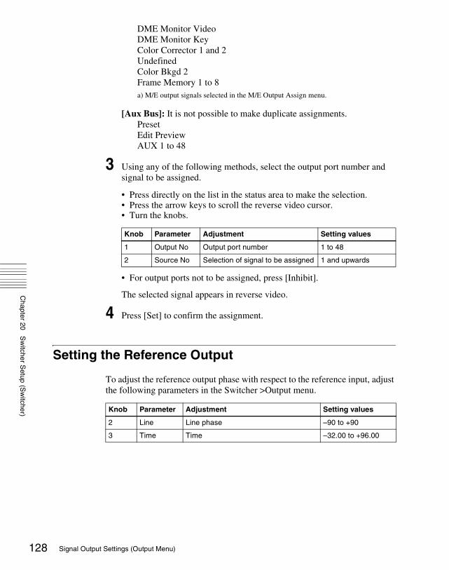
Chapter 20
Sw
itcher Setup (S
witcher)
128
DME Monitor VideoDME Monitor KeyColor Corrector 1 and 2UndefinedColor Bkgd 2Frame Memory 1 to 8a) M/E output signals selected in the M/E Output Assign menu.
[Aux Bus]: It is not possible to make duplicate assignments.PresetEdit PreviewAUX 1 to 48
3 Using any of the following methods, select the output port number and signal to be assigned.
• Press directly on the list in the status area to make the selection.• Press the arrow keys to scroll the reverse video cursor.• Turn the knobs.
• For output ports not to be assigned, press [Inhibit].
The selected signal appears in reverse video.
4 Press [Set] to confirm the assignment.
Setting the Reference Output
To adjust the reference output phase with respect to the reference input, adjust the following parameters in the Switcher >Output menu.
Knob Parameter Adjustment Setting values
1 Output No Output port number 1 to 48
2 Source No Selection of signal to be assigned 1 and upwards
Knob Parameter Adjustment Setting values
2 Line Line phase –90 to +90
3 Time Time –32.00 to +96.00
Signal Output Settings (Output Menu)

Chapter 20
Sw
itcher Setup (S
witcher)
Setting the Output Signal
In the following adjustment/setting operations, use any of the following methods to select the output signal before making the setting.• Press directly on the list in the status area.• Press the arrow keys to scroll the reverse video cursor.• Turn the knob.
The selected output signal appears in reverse video.
Adjusting the video clipTo adjust the clip value for each of the output signals from the Output 1 to 48 ports, use the following procedure.
1 In the Switcher >Output menu, press [Video Clip].
The Video Clip menu appears.The status area shows the output ports and assigned signals, and the white clip, dark clip, and chrominance clip values.
2 Adjust the following parameters.
To set the values to the default values, press [Default].
Making vertical blanking interval adjustment and through mode settings
1 In the Switcher >Output menu, press [V Blank/Through].
The V Blank/Through menu appears.The status area shows the output ports and the assigned signals, the vertical blanking interval, and the through mode Enable/Disable status.
2 Press [V Blank Mask].
Knob Parameter Adjustment Setting values
1 Output No Output port number selection 1 to 48
Knob Parameter Adjustment Setting values
2 White Clip Luminance signal white clip value 90.00 to 109.02
3 Dark Clip Luminance signal dark clip value –6.85 to +10.00
4 Chroma Clip Chrominance signal clip value 90.00 to 113.17
129Signal Output Settings (Output Menu)

Chapter 20
Sw
itcher Setup (S
witcher)
130
3 Adjust the parameter.
a) Depending on the signal format, the adjustment range varies as follows.• 480i: 10 to 19• 576i: 6 to 22
To return the values to their defaults, press [Default].
4 To enable the through mode, press [Through Mode], setting it to Enable.The through mode can be applied to the following outputs.
• Aux 1 to 48 outputs• Program outputs of the M/E and PGM/PST rows• Clean outputs of the M/E and PGM/PST rows
Making safe title settings
1 In the Switcher >Output menu, press [Safe Title].
The Safe Title menu appears.The status area shows the output ports and the assigned signals, with the box 1, box 2, and cross states.
2 To enable the safe title on/off setting made in the Misc menu, press [Safe Title], turning it on.
3 Carry out either of the following operations.
To display a box: Press [Box1] or [Box2], turning it on.In this case, carry out the following steps 4 and 5.
To display a cross: Press [Cross], turning it on.
4 When you selected [Box1] or [Box2] in step 3, adjust the following parameters.
a) Adjustable for Box2
5 When in step 3 you selected [Box1] or [Box2], in the <Box1 Adjust> or <Box2 Adjust> group, select the screen aspect ratio (16:9/14:9/4:3).
Knob Parameter Adjustment Setting values
2 Mask End Final value for vertical blanking interval
See note a) below
Knob Parameter Adjustment Setting values
2 Box Size Box size 50.00 to 100.00
3 Luminance Display brightness 0.00 to 100.00 a)
Signal Output Settings (Output Menu)

Chapter 20
Sw
itcher Setup (S
witcher)
Cropping the image to a 4:3 aspect ratio in an HD systemIn an HD system, to crop an image having a screen aspect ratio of 4:3 to an aspect ratio of 4:3, use the following procedure.
NoteThis setting is disabled for the DVS-9000 system.
1 In the Switcher >Output menu, press [4:3 Crop].
The 4:3 Crop menu appears.The status area shows the output ports and respective 4:3 Crop mode settings.
2 Press [4:3 Crop], turning it on.
This enables the crop setting, and this is reflected in the status area.
NoteWhen the screen aspect ratio of 16:9 is selected for all M/E banks in the System >Format >Active Line/Aspect menu, the setting of 4:3 Crop is disabled.
131Signal Output Settings (Output Menu)

Chapter 20
Sw
itcher Setup (S
witcher)
132
Settings Relating to Video Switching (Transition Menu)
For settings relating to video switching, use the Switcher >Transition menu.
To display the Transition menuIn the Engineering Setup menu, select VF3 ‘Switcher’ and HF4 ‘Transition.’The status area shows the transition preview, key transition, bus toggle, and split fader settings for each M/E and PGM/PST bank.
The following functions are available here.• Transition Preview: Specify the operation mode for transition preview for
each of the M/E and PGM/PST banks.• Key Transition: Specify the operation mode for independent key
transitions.• Bus Toggle: Switch the bus toggle for each of the M/E and PGM/PST banks
on or off.• Preset Color Mix: Set the stroke mode for a preset color mix, the key status
for a transition including a key, and the mode in which the transition type after a transition ends returns to the previous setting.
• Transition Curve: Set the relationship when carrying out a transition, between the fader lever position and the advancement state of the transition.
Selecting the Bank to Make the Settings
In the Transition menu, using any of the following methods, select the bank to which the settings apply, then make the settings.• Press directly on the list in the status area.• Press the arrow keys to scroll the reverse video cursor.• Turn the knob.
The selected bank appears in reverse video.
Setting the transition preview modeTo select the transition preview mode, in the <Transition Preview> group of the Transition menu, select either of the following.One Time: The transition preview ends after a single transition.
Knob Parameter Adjustment Setting values
1 Bank M/E or P/P selection to which settings apply 1 to 4
Settings Relating to Video Switching (Transition Menu)

Chapter 20
Sw
itcher Setup (S
witcher)
Normal: Switching the [TRANS PVW] button on or off switches between the transition preview mode and the normal mode.
Selecting the transition mode of the independent key transition control block
To select the key transition mode, select either of the following in the <Key Transition> group of the Transition menu.Same: The transition settings for the On and Off directions are the same.Independ: The transition settings for the On and Off directions can be set
separately.
Selecting the background transition flip-flop modeIn the Transition menu, press [Bus Toggle], to switch between on and off.On: Flip-flop modeOff: Bus fixed mode
For more details, see “Fader Lever Operation in Bus Fixed Mode” in Chapter 3 (Volume 1).
Setting the split fader to be enabled or disabledIn the Transition menu, press [Split Fader] to switch between Enable and Disable. This setting is only valid when using a simple transition module with Bus Toggle set to Off.
NoteThis setting is disabled for the CCP-9000/9000A.
Enable: When the fader lever is split, the split fader effect is enabled.Disable: Even when the fader lever is split, the normal fader lever effect is
obtained.
Enabling or disabling the fade-to-black function
In the <FTB> group of the Transition menu, press the program output name to toggle between On and Off.
NoteThis setting is disabled for the CCP-9000/9000A.
On: When the [FTB] button is pressed, a fade-to-black is carried out.Off: Even when the [FTB] button is pressed, no fade-to-black is carried out.
133Settings Relating to Video Switching (Transition Menu)

Chapter 20
Sw
itcher Setup (S
witcher)
134
NoteThe PGM2 to PGM4 settings are only valid in Multi Program mode or DSK mode.
Setting a preset color mix
1 In the Switcher >Transition menu, press [Preset Color Mix].
The Preset Color Mix menu appears.The status area shows the stroke mode setting for each M/E bank, the setting for whether or not the key status is maintained, and the one-time mode setting.
2 In the <Stroke Mode> group, select whether to carry out a transition in one stroke or two strokes.
Normal: Carry out a preset color mix with two transition operations.Single: Carry out a preset color mix with a single transition operation.
Note In bus fixed mode (see page 133), the setting is fixed to “Single.”
3 In the <Non Drop Key> group, select the key setting for a transition including a key.
To carry out the transition with the key state maintained, press [Key1] to [Key4], turning them on. (See “Transition Types” in Chapter 1 (Volume 1).)
4 If each time a transition ends the transition type is to return to the previous setting, press [One Time Enable].
Settings relating to fader lever operationsTo select the way in which the fader lever position and the transition progress are related, use the following procedure.
1 In the Switcher >Transition menu, press [Transition Curve].
The Transition Curve menu appears.
2 In the <Fader Curve> group, select the fader lever operation mode.
Normal: The transition progress is linear, according to the fader lever position. (Factory default setting)
Adv Tally Mode: When the fader lever is moved from the end of its travel, the tally is output slightly before the transition starts.
Settings Relating to Video Switching (Transition Menu)

Chapter 20
Sw
itcher Setup (S
witcher)
Settings Relating to Keys, Wipes, Frame Memory and Color Correction (Key/Wipe/FM/CCR Menu)
For settings relating to keys, wipes, frame memory and Color Correction, use the Switcher >Key/Wipe/FM/CCR menu.
To display the Key/Wipe/FM/CCR menuIn the Engineering Setup menu, select VF3 ‘Switcher’ and HF5 ‘Key/Wipe/FM/CCR.’The status area shows the key memory settings, mask and border processing order, key priority, cross-point hold, pattern limit transition, and wipe edge settings for each of the M/E and PGM/PST banks.
The following functions are available here.• Key Memory: Set the key memory operation mode for each of the M/E and
PGM/PST banks.• Video Proc Memory: Enable or disable video process memory.• Show Key: Enable or disable show key for edit preview, M/E and P/P Pvw/
K-Pvw.• Key Auto Drop: For each M/E or PGM/PST bank, specify a key to be turned
off automatically when you press a cross-point button for the bus to be output as the background.
• Mask/Border Process: Set the processing order of masks and borders for each M/E or PGM/PST bank.
• Key Priority: Set the key priority operation mode for each of the M/E and PGM/PST banks. In DSK mode, the key priority is fixed.
• Xpt Hold mode: Set the operation mode for the cross-point hold button provided on the key bus for each of the M/E and PGM/PST banks.
• Pattern Limit Transition: Set the operation mode when the pattern limit is released for each of the M/E and PGM/PST banks.
• Wipe Edge Default: Adjust the wipe edge softness for each of the M/E and PGM/PST banks.
• FM Auto Store: Switch on or off the function to automatically attach a name and save in frame memory.
Switching Video Process Memory On or Off
In the Switcher >Key/Wipe/FM/CCR menu, press [Video Proc Memory], turning it on.
135Settings Relating to Keys, Wipes, Frame Memory and Color Correction (Key/Wipe/FM/CCR Menu)

Chapter 20
Sw
itcher Setup (S
witcher)
136
Settings for the Show Key Function
1 In the Switcher >Key/Wipe/FM/CCR menu, press [Show Key].
The Show Key menu appears.
2 In the <Show Key Enable> group, press the signal for which “show key” is enabled, turning it on.
3 To set the time for which “show key” is held, press [Hold Time].
4 Adjust the following parameter.
Settings for Key Auto Drop Function
The “key auto drop” function automatically switches off a particular key when you press a cross-point button in a bus that outputs the background on the particular switcher bank (PGM/PST, or M/E-1 to M/E-3).When the background output bus is in flip-flop mode, this is always the A bus. In bus-fixed mode, it is either the A bus or the B bus depending on the fader lever position.
For details of bus-fixed mode, see “Executing a Transition” in Chapter 3 (Volume 1).
1 In the Switcher >Key/Wipe/FM/CCR menu, press [Key Auto Drop].
The Key Auto Drop menu appears.
Knob Parameter Adjustment Setting values
1 Hold Time Show key hold time 0 to 999 (frames)
Settings Relating to Keys, Wipes, Frame Memory and Color Correction (Key/Wipe/FM/CCR Menu)

Chapter 20
Sw
itcher Setup (S
witcher)
2 In the <Key Auto Drop> group, press the name of the keyer for which you want the key to be deleted automatically, turning it on.
Automatically Naming and Saving to Frame Memory
In the Switcher >Key/Wipe/FM/CCR menu, press [FM Auto Store], turning it on.
Selecting the Bank to Make the Settings
In the following procedures, select the bank to which the settings apply using any of the following methods, then make the settings.• Press directly on the list in the status area.• Press the arrow keys to scroll the reverse video cursor.• Turn the knob.
The selected bank appears in reverse video.
Selecting the key memory modeIn the <Key Memory> group of the Switcher >Key/Wipe/FM/CCR menu, select one from Full (full mode)/Simple (simple mode)/Off.
For more details, see “Key Memory” in Chapter 4 (Volume 1).
Selecting the processing order of masks and bordersIn the <Mask/Border Process> group of the Switcher >Key/Wipe/FM/CCR menu, select one of the following.Mask >Border: Apply the Mask effect, then apply the Border effect.Border >Mask: Apply the Border effect, then apply the Mask effect.
Selecting the key priority operation modeIn the <Key Priority> group of the Switcher >Key/Wipe/FM/CCR menu, select one of the following.Normal: The key priority sequence can be varied freely.Fix: Fixed at currently set priority sequence.
Knob Parameter Adjustment Setting values
1 Bank M/E or P/P selection to which settings apply 1 to 4
137Settings Relating to Keys, Wipes, Frame Memory and Color Correction (Key/Wipe/FM/CCR Menu)

Chapter 20
Sw
itcher Setup (S
witcher)
138
Setting the operation mode of the key bus [XPT HOLD] buttonIn the <Xpt Hold Mode> group of the Switcher >Key/Wipe/FM/CCR menu, select any of the following. This setting is applied for the attributes of snapshots as well as the operation mode of [XPT HOLD] button.Key Disable: The [XPT HOLD] button of the key bus functions not only as a
cross-point hold button but also as a key disable button. When the [XPT HOLD] button is on, recalling a snapshot or keyframe effect does not reflect the key settings, including the cross-point selection information.
Key Disable with Status: Same as [Key Disable], and further disables the reflection of the key on/off status.
Xpt Hold: The [XPT HOLD] button of the key bus functions as a cross-point hold button. When the [XPT HOLD] is on, recalling a snapshot or keyframe effect does not reflect the cross-point selection information.
To change the cross-point hold attribute of a snapshot If you select “Key Disable” above, this also applies key disable to the cross-point hold attribute.If you select “Key Disable With Status,” the key disable function is applied, including the key on/off status.
NoteThis setting is only reflected in the operation of the [XPT HOLD] button when the [XPT HOLD] button operating mode is set to “All Bus.” (See page 111.) Note that the snapshot cross-point hold attribute is also valid for settings other than “All Bus.”
Setting the operation mode when the pattern limit is releasedIn the <Pattern Limit Transition> group of the Switcher >Key/Wipe/FM/CCR menu, select either of the following operation modes.Auto: When the pattern limit is released, the remainder of the transition is
carried out automatically at a special-purpose transition rate.Manual: After the pattern limit is released, the transition waits for the next
operation, then executes. Until you move the fader lever or press [AUTO TRANS], the transition is not executed.
Setting the default wipe edge softness
1 In the Switcher >Key/Wipe/FM/CCR menu, press [Wipe Edge Default], turning it on.
Settings Relating to Keys, Wipes, Frame Memory and Color Correction (Key/Wipe/FM/CCR Menu)

Chapter 20
Sw
itcher Setup (S
witcher)
2 Set the following parameter.
Setting the mode in which all signals can be selected for input to the color corrector
Press [CCR Internal Signal Enable] in the Switcher > Key/Wipe/FM/CCR menu, turning it on. You can select signals generated internally to the switcher as material for input to the color corrector.
NoteWhen you select an M/E reentry signal as material for input to the color corrector, 1H delay occurs to the output signal of M/E.
Knob Parameter Adjustment Setting values
3 Soft Default value of wipe edge softness
–50.00 to +50.00
139Settings Relating to Keys, Wipes, Frame Memory and Color Correction (Key/Wipe/FM/CCR Menu)

Chapter 20
Sw
itcher Setup (S
witcher)
140
Settings Relating to Function Links (Link Menu)
Carry out setup relating to links by displaying the Switcher >Link menu.
To display the Link menuIn the Engineering Setup menu, select VF3 ‘Switcher’ and HF6 ‘Link.’The status area shows the current link information.
The following functions are available here.• Internal Bus Link: Make a setting of the bus link function that links
together two buses internal to the switcher.• GPI Link: Make settings for linking any cross-point buttons or [CUT] and
[AUTO TRANS] buttons in the cross-point control block and GPI output ports.
• M/E Link: Make settings to link together two M/E banks.• Key Trans Link: Make settings to link key transitions.
Setting a Cross-Point Button Link
To link together two buses internal to the switcher, use the following procedure.
1 In the Switcher >Link menu, press [Internal Bus Link].
The Internal Bus Link menu appears.The status area shows the link source and link destination buses, and link table information.
2 Using any of the following methods, select what setting applies to.
• Press directly on the list in the status area.• Press the arrow keys to scroll the reverse video cursor.• Turn the knob.
3 Press [Link Bus Select].
The Link Bus Select menu appears.
Knob Parameter Adjustment Setting values
1 Link No Link number 1 to 64
Settings Relating to Function Links (Link Menu)

Chapter 20
Sw
itcher Setup (S
witcher)
The status area lists the current setting status of the selected link and the buses that can be selected.
4 In the <Bus Select> group, select [Master Bus] (link source bus).
5 Using any of the following methods, select the bus to be the link source, and press [Bus Set].
• Press directly on the list appearing in the status area.• Press the arrow keys to scroll the reverse video cursor.• Turn the knob.
a) Only when [Master Bus] is selected, M/E-1 to M/E-3 Trans PGM, and P/P Trans PGM are available. Only when [Linked Bus] is selected, AUX 1 to AUX 48 as Key and MON 1 to MON 8 as Key are available.
NoteWith one of M/E-1 to M/E-3 Trans PGM and P/P Trans PGM selected for [Master Bus], the link setting become effective as soon as you start moving the fader lever.
6 In the <Bus Select> group, select [Linked Bus] (link destination bus).
7 Referring to step 5, select the bus to be the link destination, and press [Bus Set].
8 Turn the knob to select the link table, and press [Link Table Set].
For more information about link tables, see the following item.
The selected link table number is confirmed, and this is reflected in the status area.
To delete a linkSelect the link you want to delete, then press [Clear] in the Switcher >Link >Internal Bus Link menu.
Knob Parameter Adjustment Setting values
2 No Bus selection 1 to 190 a)
Knob Parameter Adjustment Setting values
3 Link Table No Link table selection 1 to 8
141Settings Relating to Function Links (Link Menu)

Chapter 20
Sw
itcher Setup (S
witcher)
142
Making Link Table Settings
1 In the Switcher >Link >Internal Bus Link menu, press [Link Table Select].
The Link Table Select menu appears.
2 Using any of the following methods, select the link source and link destination signals.
• Press directly on the list in the status area.• Press the arrow keys to scroll the reverse video cursor.• Turn the knobs.
3 To confirm the selection, press [Link Src Set].
This links the link destination signal to the signal selected as Main No.
To initialize the set source addressIn the Switcher >Link >Link Table Select menu, press [Init Link Table].A confirmation message appears; press [Yes].The source addresses are reassigned, and this is reflected in the status area.
To change the link number and link table numberIn this menu too, you can change the link number and link table number. To do this, turn the knobs as follows to make the setting, then press [Link Table Set].
Linking Cross-Point Buttons and GPI Output Ports
To link cross-point buttons or the [CUT] and [AUTO TRANS] buttons in the cross-point control block, and GPI output ports, use the following procedure.
1 In the Switcher >Link menu, press [GPI Link], to display the Switcher >Link >GPI Link menu.
The status area shows the output ports and the link status, and delay value information.
Knob Parameter Adjustment Setting values
4 Main No Video/key signal for link source 1 to 128
5 No Video/key signal for link destination 1 to 128
Knob Parameter Adjustment Setting values
1 Link No Link to which setting applies 1 to 64
3 Link Table No Link table selection 1 to 8
Settings Relating to Function Links (Link Menu)

Chapter 20
Sw
itcher Setup (S
witcher)
2 Using any of the following methods, select the GPI output port.
• Press directly on the list in the status area.• Press the arrow keys to scroll the reverse video cursor.• Turn the knob.
3 Press [GPI Link Adjust].
The GPI Link Adjust menu appears.The status area shows the current setting state of the selected link, and a list of the selectable video names or button names, together with the GPI link Enable/Disable setting for each bus.
4 Using any of the following methods, select what the setting applies to. For each GPI port there can be up to eight links.
• Press directly on the list in the status area.• Press the arrow keys to scroll the reverse video cursor.• Turn the knobs.
a) These include main pair numbers 1 to 128, and “Cut” and “Auto Trans” on each bank.
5 In the <Video/Button> group, press [Select].
The selected video or button name is reflected in the status area.
To clear a video/button name linkMake the selection to which the setting applies, then in the <Video/Button> group press [Clear].
6 To select for each bus whether the GPI link setting is enabled or disabled, use any of the following methods to select the bus to which the setting applies.
• Press directly on the list in the status area.• Press the arrow keys to scroll the reverse video cursor.• Turn the knob.
Knob Parameter Adjustment Setting values
1 GPI Port GPI output port selection 1 to 8
Knob Parameter Adjustment Setting values
1 GPI Port GPI output port selection 1 to 8
2 Link No Link number selection 1 to 8
3 Video/Button No Selection of video or button name to be linked
1 to 136 a)
143Settings Relating to Function Links (Link Menu)

Chapter 20
Sw
itcher Setup (S
witcher)
144
7 In the <Bus> group, select any of the following.
Enable: Enable the GPI link setting for the selected bus.Disable: Disable the GPI link setting for the selected bus.All Enable: Enable the GPI link setting for all buses.
Setting the delay value
1 In the Switcher >Link >GPI Link Adjust menu, turn the knobs to select the output port for which you want to set the delay value, and the corresponding delay value.
2 Press [Delay Set].
This confirms the delay value, which is reflected in the status area.
Making a Setting for Linking Two M/E Banks
You can link any two M/E banks for some operations by using the Switcher >Link >M/E Link menu.The operations for which you can link two M/E banks are as follows.• Transition execution (auto transition, cut, and fader lever operation)• Next transition selection• Transition type selection
NoteClip transition execution is excluded from the above transition execution operations.
1 In the Switcher >Link menu, press [M/E Link].
The M/E Link menu appears.The status area displays a link list showing link source banks (M/E and PGM/PST) and link destination banks, and a selection list.
Knob Parameter Adjustment Setting values
4 Bus Bus selection 1 to 114
Knob Parameter Adjustment Setting values
1 GPI Port GPI output port for the setting
1 to 8
5 Delay Delay value for the output port
0 to 300 (fields)
Settings Relating to Function Links (Link Menu)

Chapter 20
Sw
itcher Setup (S
witcher)
2 Using any of the following methods, select the link number you want to set.
• Press directly on the list in the status area.• Press the arrow keys to scroll the reverse video cursor.• Turn the knob.
3 In the <M/E Select> group, select [Master M/E] (link source).
4 Using any of the following methods, select the M/E or PGM/PST bank you want to be the link source, then press [M/E Set].
• Press directly on the list in the status area.• Press the arrow keys to scroll the reverse video cursor.• Turn the knob.
a) 1: M/E-12: M/E-23: M/E-34: PGM/PST
5 In the <M/E Select> group, select [Linked M/E] (link destination).
6 In the same way as in step 4, select the M/E or PGM/PST bank you want to be the link destination, then press [M/E Set].
To link the banks not only for transition execution but also for the other operationsPress [Transition Only], turning it off.
To release the link settingUse the same operation as in step 2 to select the link number for which you want to release the link setting, then press [Clear].
Making a Link Setting for Key Transition
You can make a link setting for key transition by using the Switcher >Link >Key Transition Link menu.The operations for which you can link two banks are the following independent key transition operations.
Knob Parameter Adjustment Setting values
1 Link No Link number selection 1 to 8
Knob Parameter Adjustment Setting values
2 No Bank selection 1 to 4 a)
145Settings Relating to Function Links (Link Menu)

Chapter 20
Sw
itcher Setup (S
witcher)
146
• Auto transition• Turning the key on or off• Fader lever operation (on the downstream key control block)
1 In the Switcher >Link menu, press [Key Trans Link].
The Key Transition Link menu appears.The status area displays a link list showing link sources and link destinations, and a key selection list.
2 Using any of the following methods, select the link number you want to set.
• Press directly on the list in the status area.• Press the arrow keys to scroll the reverse video cursor.• Turn the knob.
3 In the <Key Select> group, select [Master Key] (link source).
4 Using any of the following, select the key you want to be the link source, then press [Key Set].
• Press directly on the list in the status area.• Press the arrow keys to scroll the reverse video cursor.• Turn the knob.
a) The keys and their numbers selectable as link source/link destination are as follows.M/E-1 Key1 (1), M/E-1 Key2 (2), M/E-1 Key3 (3), M/E-1 Key4 (4), M/E-2 Key1 (5), M/E-2 Key2 (6), M/E-2 Key3 (7), M/E-2 Key4 (8), M/E-3 Key1 (9), M/E-3 Key2 (10), M/E-3 Key3 (11), M/E-3 Key4 (12), DSK1 (13), DSK2 (14), DSK3 (15), and DSK4 (16)
5 In the <Key Select> group, select [Linked Key] (link destination).
6 In the same way as in step 4, select the key you want to be the link destination, then press [Key Set].
To release the link settingUse the same operation as in step 2 to select the link number for which you want to release the link setting, then press [Clear].
Knob Parameter Adjustment Setting values
1 Link No Link number selection 1 to 32
Knob Parameter Adjustment Setting values
2 No Key number selection 1 to 16 a)
Settings Relating to Function Links (Link Menu)

Chapter 20
Sw
itcher Setup (S
witcher)
Interfacing With External Devices (Device Interface Menu)
To carry out setup relating to connections with external devices, display the Switcher >Device Interface menu.
To display the Device Interface menuIn the Engineering Setup menu, select VF3 ‘Switcher’ and HF7 ‘Device Interface.’
The following functions are available here.• Remote Assign: Set the use of the four 9-pin ports.• GPI Input: Set the GPI input ports and trigger polarities, and make the
action settings.• GPI Output: Set the GPI output ports and trigger polarities, and make the
action settings.• Aux Control: Set whether operations on the AUX buses from the four 9-pin
ports are inhibited.• DME Type Setting: When the DME is an MVE-9000 or MVE-8000A, carry
out interface settings, and for an SDI interface set the AUX bus outputs and reentry inputs.
Making 9-Pin Port Device Interface Settings
The description in this section takes the REMOTE1 port as an example. For other REMOTE ports, carry out the same process as required.
1 In the Switcher >Device Interface menu, press [Remote Assign].
The Remote Assign menu appears.
2 Select the device interface you want to set for the REMOTE1 port from the <Remote1> group.
Editor A: assign Editor A to the REMOTE1 port.Editor B: assign Editor B to the REMOTE1 port.AUX: assign AUX to the REMOTE1 port.DME1: assign DME1 to the REMOTE1 port.
147Interfacing With External Devices (Device Interface Menu)

Chapter 20
Sw
itcher Setup (S
witcher)
148
NoteWhen REMOTE3 and REMOTE4 are respectively assigned to DME1 and DME2, you can switch the AUX bus from the DME (DME-3000/7000) connected to these ports.At this time, connect the DME input video signals and key signals as follows.• DME1 video input: AUX1 output• DME1 key input: AUX2 output• DME2 video input: AUX4 output• DME2 key input: AUX5 outputNote that for a DME external video signal, you can select any of AUX1 to AUX14 on the DME. Connect to the selected AUX bus.
Making Switcher Processor GPI Input Settings
1 In the Switcher >Device Interface menu, press [GPI Input].
The GPI Input menu appears.
2 Using any of the following methods, select the settings.
• Press directly on the list in the status area.• Press the arrow keys to scroll the reverse video cursor.• Turn the knobs.
3 In the <Trigger Type> group, select the trigger type.
(Rising Edge): Apply the trigger on a rising edge of an input pulse.
(Falling Edge): Apply the trigger on a falling edge of an input pulse.
(Any Edge): Apply the trigger on a change in the polarity of the input signal.
(Level): Carry out the specified operation when the input is low or high.
No Operation: Apply no trigger on an input pulse.
4 In the <Target> group, select the action block.
M/E-1, M/E-2, M/E-3, P/P: Set the action for one of the banks.
Knob Parameter Adjustment Setting values
1 Port Port selection 1 to 8
2 No Selection of number for action to be assigned
1 to 8
Interfacing With External Devices (Device Interface Menu)

Chapter 20
Sw
itcher Setup (S
witcher)
Common/Setup: Set an action for something other than the above, or a setup action.
5 Using any of the following methods, select the action to be set.
• Press directly on the list in the status area.• Press the arrow keys to scroll the reverse video cursor.• Turn the knobs.
a) As for the setting values, see “Selectable actions for various trigger types” (page 149).b) When knob 3 selection is “Key Snapshot”c) When knob 3 selection is “Snapshot” or “Effect”
6 Press [Action Set] to confirm the action selection.
The selected setting appears in the status area.
Selectable actions for various trigger types• When the trigger type is other than “Level”
When Target is M/E-1, M/E-2, or M/E-3: Cut, Auto TransKey1 Cut, Key1 Auto Trans, Key2 Cut, Key2 Auto Trans, Key3 Cut, Key3 Auto Trans, Key4 Cut, Key4 Auto TransSS ? Recall, Key1 SS ? Recall, Key2 SS ? Recall, Key3 SS ? Recall, Key4 SS ? RecallEffect ? Recall, Effect ? Recall & Run, KF Run, KF Stop, KF Rewind, KF Reverse Run, No Action
When Target is P/P: Cut, Auto TransDSK1 Cut, DSK1 Auto Trans, DSK2 Cut, DSK2 Auto Trans, DSK3 Cut, DSK3 Auto Trans, DSK4 Cut, DSK4 Auto TransFTB Cut, FTB Auto TransSS ? Recall, DSK1 SS ? Recall, DSK2 SS ? Recall, DSK3 SS ? Recall, DSK4 SS ? Recall Effect ? Recall, Effect ? Recall & Run, KF Run, KF Stop, KF Rewind, KF Reverse Run, No Action
When Target is Common/Setup: FM Src1 Field Freeze, FM Src1 Frame Freeze, FM Src2 Field Freeze, FM Src2 Frame FreezeFM Src1 Freeze Off, FM Src2 Freeze OffFM Src1 Clip Record, FM Src1 Clip Stop, FM Src2 Clip Record, FM Src2 Clip Stop, FM1 to FM8 Clip Cueup, FM1 to FM8 Clip Play, FM1 to FM8 Clip Stop, User1 to 8 SS ? Recall, User1 to 8 EFF ? Recall, User1 to 8 EFF ?
Knob Parameter Adjustment Setting values
3 Action Action selection 1 and upwards a)
4 Reg No Register number 1 to 4 b)
1 to 99 c)
149Interfacing With External Devices (Device Interface Menu)
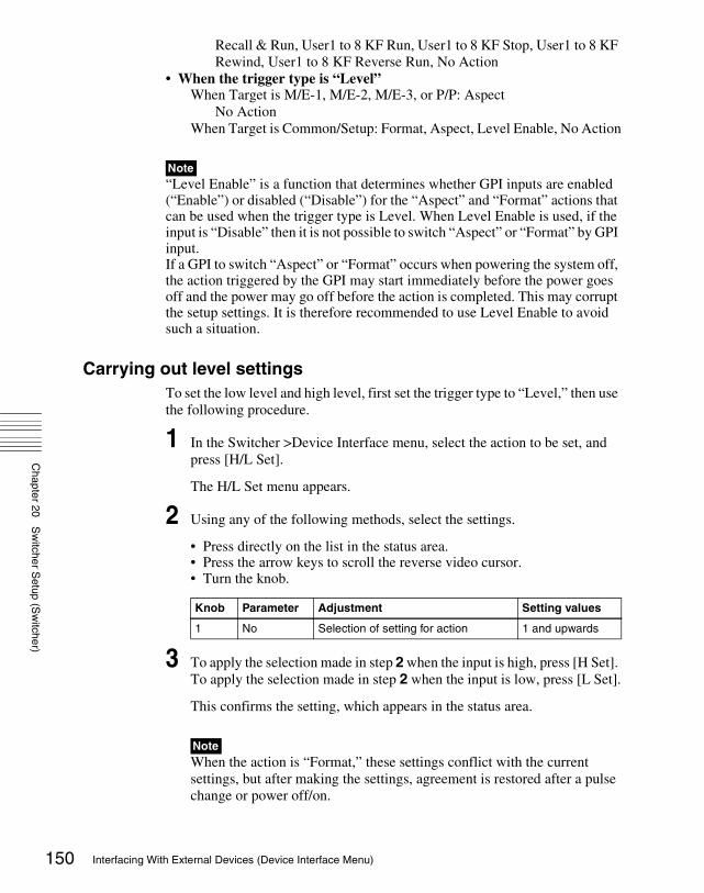
Chapter 20
Sw
itcher Setup (S
witcher)
150
Recall & Run, User1 to 8 KF Run, User1 to 8 KF Stop, User1 to 8 KF Rewind, User1 to 8 KF Reverse Run, No Action
• When the trigger type is “Level”When Target is M/E-1, M/E-2, M/E-3, or P/P: Aspect
No ActionWhen Target is Common/Setup: Format, Aspect, Level Enable, No Action
Note“Level Enable” is a function that determines whether GPI inputs are enabled (“Enable”) or disabled (“Disable”) for the “Aspect” and “Format” actions that can be used when the trigger type is Level. When Level Enable is used, if the input is “Disable” then it is not possible to switch “Aspect” or “Format” by GPI input.If a GPI to switch “Aspect” or “Format” occurs when powering the system off, the action triggered by the GPI may start immediately before the power goes off and the power may go off before the action is completed. This may corrupt the setup settings. It is therefore recommended to use Level Enable to avoid such a situation.
Carrying out level settingsTo set the low level and high level, first set the trigger type to “Level,” then use the following procedure.
1 In the Switcher >Device Interface menu, select the action to be set, and press [H/L Set].
The H/L Set menu appears.
2 Using any of the following methods, select the settings.
• Press directly on the list in the status area.• Press the arrow keys to scroll the reverse video cursor.• Turn the knob.
3 To apply the selection made in step 2 when the input is high, press [H Set]. To apply the selection made in step 2 when the input is low, press [L Set].
This confirms the setting, which appears in the status area.
NoteWhen the action is “Format,” these settings conflict with the current settings, but after making the settings, agreement is restored after a pulse change or power off/on.
Knob Parameter Adjustment Setting values
1 No Selection of setting for action 1 and upwards
Interfacing With External Devices (Device Interface Menu)

Chapter 20
Sw
itcher Setup (S
witcher)
Making Switcher Processor GPI Output Settings
1 In the Switcher >Device Interface menu, press [GPI Output].
The GPI Output menu appears.
2 Using any of the following methods, select the settings.
• Press directly on the list in the status area.• Press the arrow keys to scroll the reverse video cursor.• Turn the knob.
3 In the <Trigger Type> group, select the trigger polarity.
(Rising Edge): The trigger causes the relay contacts to be open-circuit or drives the output high, and holds this state for the specified pulse width.
(Falling Edge): The trigger causes the relay contacts to be shorted or drives the output low, and holds this state for the specified pulse width.
(Any Edge): Each time the trigger occurs, the relay contacts are alternately closed or opened, or the output is switched between high and low.
Status: Depending on the status, the relay contacts are closed or opened, or the output is switched between high and low.
No Operation: The trigger has no effect on the output.
4 Turn the knobs to select the pulse width and timing to be set.
a) 1: Field 1, 2: Field 2, 3: Any
When “ ” is selected as the trigger polarity, there is no Pulse Width setting. When “Status” is selected, there is no Pulse Width or Timing setting.
5 In the <Source> group, select the action block.
M/E-1 to M/E-3 and P/P: Set an action for the M/E or PGM/PST bank.Common: Set an action for error status.
Knob Parameter Adjustment Setting values
1 Port Port selection 1 to 8
Knob Parameter Adjustment Setting values
3 Pulse Width Pulse width 1 to 60 (fields)
4 Timing Output timing 1 to 3 a)
151Interfacing With External Devices (Device Interface Menu)

Chapter 20
Sw
itcher Setup (S
witcher)
152
6 Using any of the following methods, select the action to be set.
• Press directly on the list appearing in the status area.• Press the arrow keys to scroll the reverse video cursor.• Turn the knobs.
a) • Action list when the trigger type is other than “Status”When Source is M/E-1, M/E-2, or M/E-3: Cut, Auto Trans
Key1 Cut, Key1 Auto Trans, Key2 Cut, Key2 Auto Trans, Key3 Cut, Key3 Auto Trans, Key4 Cut, Key4 Auto TransKey1 SS ? Recall, Key2 SS ? Recall, Key3 SS ? Recall, Key4 SS ? RecallEffect ? Recall, Effect ? Recall & Run, KF Run, KF Stop, KF Rewind, No Action
When Source is P/P: Cut, Auto TransDSK1 Cut, DSK1 Auto Trans, DSK2 Cut, DSK2 Auto Trans, DSK3 Cut, DSK3 Auto Trans, DSK4 Cut, DSK4 Auto TransFTB Cut, FTB Auto TransDSK1 SS ? Recall, DSK2 SS ? Recall, DSK3 SS ? Recall, DSK4 SS ? RecallEffect ? Recall, Effect ? Recall & Run, KF Run, KF Stop, KF Rewind, No Action
When Source is Common: No Action• Action list when the trigger type is “Status”
When Source is M/E-1, M/E-2 or M/E-3: Key1 On, Key2 On, Key3 On, Key4 OnNo Action
When Source is P/P: DSK1 On, DSK2 On, DSK3 On, DSK4 OnNo Action
When Source is Common: Error Make, Error Break, No Actionb) When knob 2 selection is “Key Snapshot”c) When knob 2 selection is “Snapshot” or “Effect”
7 Press [Action Set] to confirm the action selection.
The selected setting appears in the status area.
Test firing the triggerTo test fire the trigger, press [Test Fire].This outputs a trigger from the selected output port. This is not output when the trigger type is “Status.”
Enabling or Disabling AUX Bus Control
1 In the Switcher >Device Interface menu, press [Aux Control].
The Aux Control menu appears.
Knob Parameter Adjustment Setting values
2 Action Action selection 1 and upwards a)
5 Reg No Register number 1 to 4 b)
1 to 99 c)
Interfacing With External Devices (Device Interface Menu)

Chapter 20
Sw
itcher Setup (S
witcher)
2 Select the 9-pin port for the setting, from the <Control> group.
Remote1: Make the settings for the REMOTE1 port.Remote2: Make the settings for the REMOTE2 port.Remote3: Make the settings for the REMOTE3 port.Remote4: Make the settings for the REMOTE4 port.
3 Using any of the following methods, select the AUX bus.
• Press directly on the list in the status area.• Press the arrow keys to scroll the reverse video cursor.• Turn the knob.
a) 0: EDIT PVW1 to 48: AUX1 to AUX48
4 Select whether to enable or disable AUX bus control from the <Control Mode> group.
Enable: enable control of the port selected in step 2.Disable: disable control of the port selected in step 2.Manual: make whether control of the port selected in step 2 is possible or
not depend on the setting in the Misc menu.
5 Repeat steps 2 to 4 as required to make the settings for other ports.
Setting the Interface Between the DME and the Switcher
To set the interface between the DME and the switcher when the DME is an MVE-8000A or MVE-9000, proceed as follows.
1 In the Switcher >Device Interface menu, press [DME Type Setting].
The DME Type Setting menu appears.
2 In the <DME1 Type> group to set DME1 or in the <DME2 Type> group to set DME2, press [SDI], turning it on. ([Dedicated] is disabled.)
Dedicated: The MVE-8000A/MVE-9000 has an MVS-8000-series dedicated interface.
SDI: The MVE-8000A/MVE-9000 has an SDI interface.
Knob Parameter Adjustment Setting values
1 No AUX bus selection 0 to 48 a)
153Interfacing With External Devices (Device Interface Menu)

Chapter 20
Sw
itcher Setup (S
witcher)
154
3 To select the number of keys that use DME on an M/E bank, make one of the following selections in the <DME Assigned Key per M/E> group.
NoteThis setting is disabled for the CCP-9000/9000A.
Up to 2 Keys: Mode in which a processed key operation is carried out only with the dedicated interface DME or the SDI interface DME.
Up to 3 Keys: Mode in which two processed key operations with the dedicated interface DME and the SDI interface DME are both possible simultaneously on the same M/E. When this mode is selected, when combined by a processed key with the SDI interface DME, select the material for the second channel not on the DME external video bus, but on the AUX bus.
Setting the AUX Bus Output and Reentry Input
Select the signal input to the DME (AUX bus output) and the signal returned as the switcher primary input (reentry input) as follows.
NoteBefore the following operations, carry out the procedure described in the previous item “Setting the Interface Between the DME and the Switcher.”
1 In the Switcher >Device Interface menu, press [DME Type Setting].
The DME Type Setting menu appears.
2 Press [DME SDI Interface].
The DME SDI Interface menu appears.
3 Using any of the following methods, select the DME channel to which operations apply.
• Press directly on the list on the left of the status area.• Press the arrow keys to scroll the reverse video cursor.• Turn the knob.
Knob Parameter Adjustment Setting values
1 DME Ch No DME channel selection 1 to 24
Interfacing With External Devices (Device Interface Menu)

Chapter 20
Sw
itcher Setup (S
witcher)
Notes • When using the MVE-8000A, it is not possible to select any of DME 1
Ext In to DME 8 Ext In.• When using the BKDS-9470, it is not possible to select DME 1 to DME
8 (video/key).
4 In the <Select> group, select the AUX bus or reentry to be assigned to the DME channel.
Aux Bus: Set AUX bus.Re-Entry: Set reentry.
5 Depending on the selection in step 4, use any of the following methods to make the setting.
• Press directly on the list on the right of the status area.• Press directly on the list on the right of the status area.• Press the arrow keys to scroll the reverse video cursor.• Turn the knob.
• When Aux Bus is selected
• When Re-Entry is selected
6 Press [Set].
In the list on the right of the status area, the selected content is reflected in the specified DME channel.
Repeat steps 3 to 6 as required.
Selecting the Mode for Turning Off Keys Upon Receiving the Editor Command
Selects the mode for turning off keys when an “All Stop” command is received from the editor.
1 In the Switcher >Device Interface menu, press [Editor I/F].
The Editor I/F menu appears.
Knob Parameter Adjustment Setting values
2 Src No AUX bus number 0 to 48
Knob Parameter Adjustment Setting values
2 Src No Reentry number 0 to 80
155Interfacing With External Devices (Device Interface Menu)

Chapter 20
Sw
itcher Setup (S
witcher)
156
2 Select one of the following modes.
All: When an “All Stop” command is received, all keys for the selected regions are turned off.
Specified: When an “All Stop” command is received, among all the keys for the selected regions, only the keys specified by the editor are turned off.
NoteWhen an “All Stop” command is received in the process of a transition, the keys selected for the next transition are also turned off.
Interfacing With External Devices (Device Interface Menu)

Chapter 21 DME Setup (DME)
Settings Relating to Signal Inputs (Input Menu) ...................................158Setting the Initial Crop ......................................................................158Setting an Illegal Color Limit for Matte Signals ...............................159Making DME System Phase Adjustment ..........................................159Setting the TBC Window Center Position ........................................159
Settings Relating to Signal Outputs (Output Menu) .............................161Adjusting the Monitor Output ...........................................................161Setting the Monitor Output ................................................................162
Interfacing With External Devices (Device Interface Menu) ...............163Making DME GPI Input Settings ......................................................164Making DME GPI Output Settings ...................................................166

Chapter 21
DM
E S
etup (DM
E)
158
Settings Relating to Signal Inputs (Input Menu)
To make settings relating to DME input signals, display the DME >Input menu.
To display the Input menuIn the Engineering Setup menu, select VF4 ‘DME’ and HF1 ‘Input.’The status area shows the initial crop information and the DME system phase.
The following functions are available here.• Initial Crop: Make the initial crop setting.• Matte Illeg. Color Limit: Switch the illegal limiter for the signal generated
by the DME internal matte generator on or off.• System Phase: Adjust the operation timing of the whole system with respect
to the reference signal.• TBC Center: Set the TBC window center position.
In the following, the settings for DME1 are explained. (It is not necessary to make settings for DME2.)
Setting the Initial Crop
1 In the DME1 <Aspect> group of the DME >Input menu, select the screen aspect ratio (16:9 or 4:3).
2 In the DME1 <Crop> group, press [Initial Crop] and adjust the following parameters.
• If you selected 4:3 in step 1
Knob Parameter Adjustment Setting values
1 Top Position of top side –3.00 to +3.00
2 Left Position of left side –4.00 to +4.00
3 Right Position of right side –4.00 to +4.00
4 Bottom Position of bottom side –3.00 to +3.00
Settings Relating to Signal Inputs (Input Menu)

Chapter 21
DM
E S
etup (DM
E)
• If you selected 16:9 in step 1
To return the parameter values to their default valuesPress [Unity] in the <Crop> group.
Setting an Illegal Color Limit for Matte Signals
To enable the illegal color limiter for the signals generated by the DME internal matte generator, press [Matte Illeg Col Limit] for DME1 in the DME >Input menu, turning it on.
Making DME System Phase Adjustment
To adjust the DME reference phase, use the following procedure.
1 In the DME >Input menu, press [System Phase].
2 Set the following parameters.
Setting the TBC Window Center Position
When the MVE-8000A/MVE-9000 is connected through SDI interface, the DME >Input >TBC Center menu allows you to set the TBC window center position.
Knob Parameter Adjustment Setting values
1 Top Position of top side –9.00 to +9.00
2 Left Position of left side –16.00 to +16.00
3 Right Position of right side –16.00 to +16.00
4 Bottom Position of bottom side –9.00 to +9.00
Knob Parameter Adjustment Setting values
1 DME1 Phase
DME1 system phase adjustment –32.00 to +96.00
2 DME2 Phase
DME2 system phase adjustment –32.00 to +96.00
159Settings Relating to Signal Inputs (Input Menu)

Chapter 21
DM
E S
etup (DM
E)
160
1 In the DME >Input menu, press [TBC Center].
The TBC Center menu appears.The status area shows the TBC center position values for DME1, DME 2, and external input signals.
Note The TBC center position values for external input signals are shown only when an SDI-interfaced MVE-9000 is used.
2 Using any of the following methods, select the input number for which you want to set the TBC center position.
• Press directly on the list in the status area.• Press the arrow keys to scroll the reverse video cursor.• Turn the knob.
3 In the <Video/Key> group (when an SDI-interfaced MVE-8000A/9000 is used) or the <External Video> group (when an SDI-interfaced MVE-9000 is used), press the desired button, and set the TBC center position to 0H, 0.5H, or 1H.
Knob Parameter Adjustment Setting values
1 No Input number selection 1 to 8
Settings Relating to Signal Inputs (Input Menu)

Chapter 21
DM
E S
etup (DM
E)
Settings Relating to Signal Outputs (Output Menu)
To make settings relating to DME output signals, display the DME >Output menu.
To display the Output menuIn the Engineering Setup menu, select VF4 ‘DME’ and HF3 ‘Output.’These settings are possible only when the DME is an MVE-9000 or SDI-interfaced MVE-8000A.
The following functions are available here.• Monitor Output: Set the signals output from the four monitor output
connectors.• Clip Adjust: Adjust the clip levels of DME1 and DME2 outputs.
Adjusting the Monitor Output
When the MVE-8000A/MVE-9000 is connected through SDI interface, you can adjust both DME1 and DME2 output video clip levels.Use the following procedure. (DME 1 is taken by way of example.)
1 In the <DME1(Ch1-Ch4)> group of the DME >Output menu, press [Clip Adjust], turning it on.
2 Set the following parameters.
To return the setting to the default valueIn the DME >Output menu, press [Default].
Knob Parameter Adjustment Setting values
1 White Clip White clip adjustment 90.00 to 109.02
2 Dark Clip Dark clip adjustment −6.85 to +10.00
3 Chroma Clip Chroma clip adjustment 90.00 to 113.17
161Settings Relating to Signal Outputs (Output Menu)

Chapter 21
DM
E S
etup (DM
E)
162
Setting the Monitor Output
To set the signals output from the four monitor output connectors, use the following procedure.
Note This setting is valid when an SDI-interfaced MVE-8000A or an MVE-9000 is used.
1 In the DME >Output menu, press [Monitor Output].
The Monitor Output menu appears.
2 In the <Select> group, select the DME to which the setting applies.
DME1: Select DME1.DME2: Select DME2.
3 In the list on the left of the status area, press directly on the monitor output for which you want to make setting.
4 In the list on the right of the status area, press directly on the signal you want to output.
5 Press [Set].
The selection is reflected in the monitor output.
Settings Relating to Signal Outputs (Output Menu)

Chapter 21
DM
E S
etup (DM
E)
Interfacing With External Devices (Device Interface Menu)
To carry out setup relating to DME connections with external devices, display the DME >Device Interface menu.
To display the Device Interface menuIn the Engineering Setup menu, select VF4 ‘DME’ and HF4 ‘Device Interface.’
The following functions are available here.• Editor Protocol: Set the protocol to be used on the Editor port.• Editor Port Setting: Make settings relating to the control of the four editor
ports installed in the DME.• GPI Input: Set the GPI input ports and trigger polarities, and make the
action settings.• GPI Output: Set the GPI output ports and trigger polarities, and make the
action settings.
In the following, the settings for DME1 are explained. (It is not necessary to make settings for DME2.)
Setting the editor protocolIn the <DME1 Editor Protocol> group of the DME >Device Interface menu, press the following buttons to make the setting.DME: Control by DME protocol through the editor port.VTR: Control by VTR protocol through the editor port.
Making editor port settingsIn the <DME1 Editor Port Setting> group of the DME >Device Interface menu,press either of the following to select the way in which the editor ports are used.Common: Control all of channels 1 to 4 through Editor ports 1 to 4.Independ: Control channels 1 to 4 individually through Editor ports 1 to 4.
Note On the MVE-8000, the setting is fixed to Common.
163Interfacing With External Devices (Device Interface Menu)

Chapter 21
DM
E S
etup (DM
E)
164
Making DME GPI Input Settings
The same GPI input is used for switcher processor control and for the MKS-6470 GPI input.
1 In the DME >Device Interface menu, press [DME1 GPI Input].
The DME1 GPI Input menu appears.
2 Using any of the following methods, select the settings.
• Press directly on the list in the status area.• Press the arrow keys to scroll the reverse video cursor.• Turn the knobs.
3 In the <Trigger Type> group, select the trigger polarity.
(Rising Edge): Apply the trigger on a rising edge of an input pulse.
(Falling Edge): Apply the trigger on a falling edge of an input pulse.
(Any Edge): Apply the trigger on a change in the polarity of the input signal.
(Level): Carry out the specified operation when the input is low or high.
No Operation: Apply no trigger on an input pulse.
4 In the <Target> group, select what this applies to (channels 1 to 4, or Proc).
5 Using any of the following methods, select the action to be set.
• Press directly on the list in the status area.• Press the arrow keys to scroll the reverse video cursor.• Turn the knobs.
a) As for the setting values, see “Selectable actions for various trigger types” (page 165).b) When knob 3 selection is “Snapshot”
Knob Parameter Adjustment Setting values
1 Port Input port selection 1 to 8
2 No Selection of number for action to be assigned
1 to 8
Knob Parameter Adjustment Setting values
3 Action Action selection 1 and upwards a)
4 Reg No Register number 1 to 99 b)
1 to 399 c)
Interfacing With External Devices (Device Interface Menu)

Chapter 21
DM
E S
etup (DM
E)
c) When knob 3 selection is “Effect”
6 Press [Action Set] to confirm the action selection.
The selected setting appears in the status area.
Selectable actions for various trigger types• When the trigger type is other than “Level”
When Target is Ch1, Ch2, Ch3, or Ch4: Freeze, SS ? RecallEffect ? Recall, Effect ? Recall & Run, KF Run, KF Stop, KF Rewind, KF Reverse Run, No Action
When Target is Proc: No Action• When the trigger type is “Level”
When Target is Ch1, Ch2, Ch3, or Ch4: Aspect, No ActionWhen Target is Proc: Format (frame/field rate, number of lines)
Aspect, Level Enable, No Action
Note“Level Enable” is a function that determines whether GPI inputs are enabled (“Enable”) or disabled (“Disable”) for the “Aspect” and “Format” actions that can be used when the trigger type is Level. When Level Enable is used, if the input is “Disable” then it is not possible to switch “Aspect” or “Format” by GPI input.If a GPI to switch “Aspect” or “Format” occurs when powering the system off, the action triggered by the GPI may start immediately before the power goes off and the power may go off before the action is completed. This may corrupt the setup settings. It is therefore recommended to use Level Enable to avoid such a situation.
Carrying out level settingsTo set the low level and high level, first set the trigger type to “Level,” then use the following procedure.
1 In the DME >Device Interface menu, select the action to be set, and press [H/L Set].
The H/L Set menu appears.
2 Using any of the following methods, select the settings.
• Press directly on the list in the status area.• Press the arrow keys to scroll the reverse video cursor.• Turn the knob.
165Interfacing With External Devices (Device Interface Menu)

Chapter 21
DM
E S
etup (DM
E)
166
3 To apply the selection made in step 2 when the input is high, press [H Set]. To apply the selection made in step 2 when the input is low, press [L Set].
This confirms the setting, which appears in the status area.
Making DME GPI Output Settings
1 In the DME >Device Interface menu, press [DME1 GPI Output].
The DME1 GPI Output menu appears.The output port selection is fixed at 1.
2 In the <Trigger Type> group, select the trigger polarity.
Status: Depending on the status, the relay contacts are closed or opened, or the output is switched between high and low.
No Operation: The trigger has no effect on the relay state or output level.
3 Using any of the following methods, select the action you want to set.
• Press directly on the list in the status area.• Press the arrow keys to scroll the reverse video cursor.• Turn the knob.
a) Error Make, Error Break, No Action
4 Press [Action Set] to confirm the action selection.
The selected setting appears in the status area.
Knob Parameter Adjustment Setting values
1 No Signal format/screen aspect ratio selection
1 and upwards
Knob Parameter Adjustment Setting values
2 Action Action selection 1 to 3 a)
Interfacing With External Devices (Device Interface Menu)

Chapter 22 DCU Setup (DCU)
Setup Relating to DCU .............................................................................168Settings Relating to Parallel Inputs (Input Config Menu) ....................169
Assigning a GPI Input Port ...............................................................169Releasing the Assignment of a GPI Input Port ..................................170
GPI Input Setting (GPI Input Assign Menu) .........................................171Making DCU GPI Input Settings ......................................................171
Parallel Output Settings (Output Config Menu) ...................................175Assigning a GPI Output Port .............................................................175Releasing the Assignment of a GPI Output Port ...............................176
GPI Output Setting (GPI Output Assign Menu) ...................................177Making DCU GPI Output Settings ....................................................177
Serial Port Settings (Serial Port Assign Menu) .....................................180Making Serial Port Settings ...............................................................180Making Detailed Settings on the External Device Connected to the Serial
Port .........................................................................................182

Chapter 22
DC
U S
etup (DC
U)
168
Setup Relating to DCU
In DCU setup, carry out settings particular to the DCU.You can make the following settings.• Input Config: Assign GPI inputs to Parallel input ports.• GPI Input Assign: Make GPI input settings.• Output Config: Assign GPI outputs to parallel output ports inserted in an
option slot.• GPI Output Assign: Make GPI output settings.• Serial Port Assign: Set the protocol to match the devices connected to a 9-
pin serial port. You can also select the control panel used to control each device.
NoteFor setup relating to DCU, it is necessary to make the same settings on multiple control panels (maximum three units) that are sharing the DCU. After carrying out the DCU setup on one control panel, make the same settings on the other control panels.
Setup Relating to DCU

Chapter 22
DC
U S
etup (DC
U)
Settings Relating to Parallel Inputs (Input Config Menu)
To assign GPI inputs to DCU parallel input ports, display the DCU >Input Config menu.The DCU parallel input ports are assigned with the following priority sequence.1. When external boxes are set in the Router/Tally >Router >External Box
Assign menu, the parallel inputs are assigned to the external box inputs in order.
2. When tally settings are carried out in the Router/Tally >Tally Enable menu, tally inputs are assigned automatically.
In this menu, you set only the input ports which are unused after making the above assignments.
To display the Input Config menuIn the Engineering Setup menu, select VF5 ‘DCU’ and HF1 ‘Input Config.’The status area shows input port information.
Assigning a GPI Input Port
1 In the DCU >Input Config menu, select what the setting applies to (DCU1 or DCU2) from the <DCU Select> group.
2 In the <Parallel Input Assign> group, press [GPI Input].
3 Using any of the following methods, assign the number of the GPI input to the input port.
• Press directly on the list in the status area.• Press the arrow keys to scroll the reverse video cursor.• Turn the knobs.
a) When the MKS-2700 is connected, select a value in the range 1 to 34.
4 To confirm the assignment in step 3, press [GPI Input Set].
Knob Parameter Adjustment Setting values
1 Parallel Input Input port 1 to 102 a)
3 GPI Input GPI input 1 to 50
169Settings Relating to Parallel Inputs (Input Config Menu)

Chapter 22
DC
U S
etup (DC
U)
170
This assigns the GPI input, and this is reflected in the status area.
Releasing the Assignment of a GPI Input Port
1 In the DCU >Input Config menu, select what the setting applies to (DCU1 or DCU2) from the <DCU Select> group.
2 In the <Parallel Input Assign> group, if [GPI Input] is on, press it to turn it off.
3 Turn the knobs to adjust the following parameters.
4 In the <Parallel Input Assign> group, press [No Assign].
Knob Parameter Adjustment Setting values
1 From No First port number 1 to To No
2 To No Last port number From No to 102
Settings Relating to Parallel Inputs (Input Config Menu)

Chapter 22
DC
U S
etup (DC
U)
GPI Input Setting (GPI Input Assign Menu)
To set the trigger type and so on for each GPI input, display the DCU >GPI Input Assign menu.
To display the GPI Input Assign menuIn the Engineering Setup menu, select VF5 ‘DCU’ and HF2 ‘GPI Input Assign.’The GPI input port setting status appears in the status area.
Making DCU GPI Input Settings
1 In the DCU >GPI Input Assign menu, using any of the following methods select what the setting applies to.
• Press directly on the list in the status area.• Press the arrow keys to scroll the reverse video cursor.• Turn the knob.
2 In the <Trigger Type> group, select the trigger polarity.
(Rising Edge): Apply the trigger on a rising edge of an input pulse.
(Falling Edge): Apply the trigger on a falling edge of an input pulse.
(Any Edge): Apply the trigger on a change in the polarity of the input signal.
(Level): Carry out the specified operation when the input is low or high.
No Operation: Apply no trigger on an input pulse.
3 In the <Target Device> group, select the control panel to handle the GPI input.
SCU1: ID1 control panel (PNL1)SCU2: ID2 control panel (PNL2)SCU3: ID3 control panel (PNL3)
Knob Parameter Adjustment Setting values
1 No GPI input 1 to 50
171GPI Input Setting (GPI Input Assign Menu)

Chapter 22
DC
U S
etup (DC
U)
172
The action set in the following step 4 is executed for the switcher and DME controlled by the selected control panel.
4 Using any of the following methods, select the action you want to set.
• Press directly on the list in the status area.• Press the arrow keys to scroll the reverse video cursor.• Turn the knobs.
a) As for the setting values, see “Selectable actions for various trigger types” (page 172)b) When knob 2 selection is “Aux ? O’ride Src ??”c) When knob 2 selection is “Key Snapshot”d) When knob 2 selection is “Snapshot”e) When knob 2 selection is “Effect”
5 To confirm the setting in step 4, press [Action Set].
This confirms the setting, which appears in the status area.
Selectable actions for various trigger types• When the trigger type is other than “Level”
M/E-1 Cut, M/E-2 Cut, M/E-3 Cut, P/P Cut, M/E-1 Auto Trans, M/E-2 Auto Trans, M/E-3 Auto Trans, P/P Auto TransM/E-1 Key1 Auto Trans, M/E-1 Key1 CutM/E-1 Key2 Auto Trans, M/E-1 Key2 CutM/E-1 Key3 Auto Trans, M/E-1 Key3 CutM/E-1 Key4 Auto Trans, M/E-1 Key4 CutM/E-2 Key1 Auto Trans, M/E-2 Key1 CutM/E-2 Key2 Auto Trans, M/E-2 Key2 CutM/E-2 Key3 Auto Trans, M/E-2 Key3 CutM/E-2 Key4 Auto Trans, M/E-2 Key4 CutM/E-3 Key1 Auto Trans, M/E-3 Key1 CutM/E-3 Key2 Auto Trans, M/E-3 Key2 CutM/E-3 Key3 Auto Trans, M/E-3 Key3 CutM/E-3 Key4 Auto Trans, M/E-3 Key4 CutP/P DSK1 Auto Trans, P/P DSK1 CutP/P DSK2 Auto Trans, P/P DSK2 CutP/P DSK3 Auto Trans, P/P DSK3 Cut
Knob Parameter Adjustment Setting values
2 Action Action selection 1 and upwards a)
4 Aux Bus No Aux bus selection 1 to 48 b)
5 Reg No Register number 1 to 4 c)
1 to 99 d)
1 to 399 e)
5 Src No Source signal selection 1 and upwards b)
GPI Input Setting (GPI Input Assign Menu)

Chapter 22
DC
U S
etup (DC
U)
P/P DSK4 Auto Trans, P/P DSK4 CutFTB Auto Trans, FTB CutMaster SS ? Recall,SS ? Recall, M/E-1 Key1 SS ? Recall, M/E-1 Key2 SS ? RecallM/E-1 Key3 SS ? Recall, M/E-1 Key4 SS ? RecallM/E-2 Key1 SS ? Recall, M/E-2 Key2 SS ? RecallM/E-2 Key3 SS ? Recall, M/E-2 Key4 SS ? RecallM/E-3 Key1 SS ? Recall, M/E-3 Key2 SS ? RecallM/E-3 Key3 SS ? Recall, M/E-3 Key4 SS ? RecallP/P DSK1 SS ? Recall, P/P DSK2 SS ? RecallP/P-1 DSK3 SS ? Recall, P/P-1 DSK4 SS ? RecallFM Src1 Field Freeze, FM Src1 Frame Freeze, FM Src1 Freeze OffFM Src2 Field Freeze, FM Src2 Frame Freeze, FM Src2 Freeze OffFM Src1 Clip Record, FM Src1 Clip Stop, FM Src2 Clip Record, FM Src2 Clip Stop, FM1 to FM8 Clip Cueup, FM1 to FM8 Clip Play, FM1 to FM8 Clip Stop, Effect ? Recall, Effect ? Recall & Run, KF Run, KF Stop, Master Effect ? RecallKF Rewind, Shotbox ? Recall, Macro Take, Macro ? Recall, No Action
• When the trigger type is only “Rising Edge” or “Falling Edge”Aux? O’ride Src??
• When the trigger type is “Level”Simul, Custom, Format (frame/field rate, number of lines)(System Format, SWR Format, DME Ch1-Ch4 Format, DME Ch5-Ch8 Format)Aspect (System Aspect, SWR Aspect, M/E-1 Aspect, M/E-2 Aspect, M/E-3 Aspect, P/P Aspect, DME Ch1-Ch4 AspectDME Ch1 Aspect, DME Ch2 Aspect, DME Ch3 Aspect, DME Ch4 Aspect, DME Ch5 AspectDME Ch6 Aspect, DME Ch7 Aspect, DME Ch8 Aspect)Level Enable, No Action
Notes• “Level Enable” is a function that determines whether GPI inputs are enabled
(“Enable”) or disabled (“Disable”) for the Aspect and Format actions that can be used when the trigger type is Level. When Level Enable is used, if the input is “Disable” then it is not possible to switch Aspect or Format by GPI input.If a GPI to switch Aspect or Format occurs when powering the system off, the action triggered by the GPI may start immediately before the power goes off and the power may go off before the action is completed. This may corrupt the setup settings. It is therefore recommended to use Level Enable to avoid such a situation.
• As for “Aux ? O’ride Src ??,” when “Rising Edge” is selected, on a rising edge the set AUX bus primary input is used. On a falling edge, the original
173GPI Input Setting (GPI Input Assign Menu)

Chapter 22
DC
U S
etup (DC
U)
174
state of the cross-point is restored. If the GPI trigger is applied repeatedly at short intervals (0.5 second or less), the cross-point switching may not be carried out correctly. In this case, apply the GPI trigger again.
Carrying out level settingsTo set the low level and high level, first set the trigger type to “Level,” then use the following procedure.
1 In the DCU >GPI Input Assign menu, select the action to be set, and press [H/L Set].
The H/L Set menu appears.
2 Using any of the following methods, select the settings.
• Press directly on the list in the status area.• Press the arrow keys to scroll the reverse video cursor.• Turn the knob.
3 To apply the selection made in step 2 when the input is the GPI high level, press [H Set]. To apply the selection made in step 2 when the input is low, press [L Set].
This confirms the setting, which appears in the status area.
Knob Parameter Adjustment Setting values
1 No Signal format/screen aspect ratio selection
1 and upwards
GPI Input Setting (GPI Input Assign Menu)

Chapter 22
DC
U S
etup (DC
U)
Parallel Output Settings (Output Config Menu)
For the DCU parallel output ports, after carrying out tally settings in the Router/Tally >Tally Enable menu, you can assign GPI outputs to output ports that are still unused.To assign DCU outputs to DCU parallel output ports, display the DCU >Output Config menu.
To display the Output Config menuIn the Engineering Setup menu, select VF5 ‘DCU’ and HF3 ‘Output Config.’The status area shows output port information.
Assigning a GPI Output Port
1 In the DCU >Output Config menu, select what the setting applies to (DCU1 or DCU2) from the <DCU Select> group.
2 In the <Parallel Output Assign> group, press [GPI Output].
3 Using any of the following methods, select the output port and GPI output number.
• Press directly on the list in the status area.• Press the arrow keys to scroll the reverse video cursor.• Turn the knobs.
a) When the MKS-2700 is connected, select 2.b) When the MKS-2700 is connected, select a value in the range 1 to 36.
4 To confirm the selected setting, press [GPI Output Set].
This confirms the selection, which is reflected in the status area.
Knob Parameter Adjustment Setting values
1 Parallel Output Slot Output port slot 2 to 6 a)
2 Parallel Output Port Output port 1 to 54 b)
5 GPI Output GPI output 1 to 50
175Parallel Output Settings (Output Config Menu)

Chapter 22
DC
U S
etup (DC
U)
176
Releasing the Assignment of a GPI Output Port
1 In the DCU >Output Config menu, select what the setting applies to (DCU1 or DCU2) from the <DCU Select> group.
2 In the <Parallel Output Assign> group, if [GPI Output] is on, press it to turn it off.
3 Turn the knobs to select the slot and port to which the setting applies.
4 In the <Parallel Output Assign> group, press [No Assign].
Knob Parameter Adjustment Setting values
1 From Slot First port slot 2 to 6
2 From Port First port number 1 to 54
3 To Slot Last port slot 2 to 6
4 To Port Last port number 1 to 54
Parallel Output Settings (Output Config Menu)

Chapter 22
DC
U S
etup (DC
U)
GPI Output Setting (GPI Output Assign Menu)
To set the trigger type and so on for each GPI output, display the DCU >GPI Output Assign menu.
To display the GPI Output Assign menuIn the Engineering Setup menu, select VF5 ‘DCU’ and HF4 ‘GPI Output Assign.’The GPI output port setting status appears in the status area.
Making DCU GPI Output Settings
1 In the DCU >GPI Output Assign menu, using any of the following methods select what the setting applies to.
• Press directly on the list in the status area.• Press the arrow keys to scroll the reverse video cursor.• Turn the knob.
2 In the <Trigger Type> group, select the trigger polarity.
(Rising Edge): The trigger causes the relay contacts to be open-circuit or drives the output high, and holds this state for the specified pulse width.
(Falling Edge): The trigger causes the relay contacts to be shorted or drives the output low, and holds this state for the specified pulse width.
(Any Edge): Each time the trigger occurs, the relay contacts are alternately closed or opened, or the output is switched between high and low.
Status: Depending on the status, the relay contacts are closed or opened, or the output is switched between high and low.
No Operation: The trigger has no effect on the relay state or output level.
3 Turning the knobs, select the pulse width and timing to be set.
Knob Parameter Adjustment Setting values
1 No GPI output 1 to 50
177GPI Output Setting (GPI Output Assign Menu)

Chapter 22
DC
U S
etup (DC
U)
178
a) 1: Field 1, 2: Field 2, 3: Any
When “ ” is selected as the trigger polarity, there is no Pulse Width setting. When “Status” is selected, there is no Pulse Width or Timing setting.
4 In the <Source Device> group, select the control panel or DCU to handle the GPI output.
SCU1: ID1 control panel (PNL1)SCU2: ID2 control panel (PNL2)SCU3: ID3 control panel (PNL3)DCU1: ID1 DCUDCU2: ID2 DCU
When the action set in the following step 5 is carried out on the control panel selected here, this causes a GPI output. It is also possible to output error information. When the DCU is selected, you can output error information by means of the action set in step 5.
5 Using any of the following methods, select the action you want to set.
• Press directly on the list in the status area.• Press the arrow keys to scroll the reverse video cursor.• Turn the knobs.
a) • Action list when the trigger type is other than “Status”When Source Device is SCU: M/E1 Key1 SS ? Recall, M/E1 Key2 SS ? Recall, M/E1
Key3 SS ? RecallM/E1 Key4 SS ? Recall, M/E2 Key1 SS ? Recall, M/E2 Key2 SS ? Recall, M/E2 Key3 SS ? Recall, M/E2 Key4 SS ? RecallM/E3 Key1 SS ? Recall, M/E3 Key2 SS ? Recall, M/E3 Key3 SS ? Recall, M/E3 Key4 SS ? RecallP/P DSK1 SS ? Recall, P/P DSK2 SS ? Recall, P/P DSK3 SS ? Recall, P/P DSK4 SS ? RecallEditor GPI-?? (executable only when the BZS-8050 license is valid)No Action
When Source Device is DCU: No Action• Action list when the trigger type is “Status”
Knob Parameter Adjustment Setting values
3 Pulse Width Pulse width 1 to 60 (fields)
4 Timing Output timing 1 to 3 a)
Knob Parameter Adjustment Setting values
2 Action Action selection 1 and upwards a)
5 Reg No Snapshot register number 1 to 4 b)
5 GPI No GPI number selection 1 to 32 c)
GPI Output Setting (GPI Output Assign Menu)

Chapter 22
DC
U S
etup (DC
U)
When Source Device is SCU: M/E1 Key1 SS ? Recall, M/E1 Key2 SS ? Recall, M/E1 Key3 SS ? Recall, M/E1 Key4 SS ? RecallM/E2 Key1 SS ? Recall, M/E2 Key2 SS ? Recall, M/E2 Key3 SS ? Recall, M/E2 Key4 SS ? RecallM/E3 Key1 SS ? Recall, M/E3 Key2 SS ? Recall, M/E3 Key3 SS ? Recall, M/E3 Key4 SS ? RecallP/P DSK1 SS ? Recall, P/P DSK2 SS ? Recall, P/P DSK3 SS ? Recall, P/P DSK4 SS ? RecallM/E1 Key1 On, M/E1 Key2 On, M/E1 Key3 On, M/E1 Key4 OnM/E2 Key1 On, M/E2 Key2 On, M/E2 Key3 On, M/E2 Key4 OnM/E3 Key1 On, M/E3 Key2 On, M/E3 Key3 On, M/E3 Key4 OnP/P DSK1 On, P/P DSK2 On, P/P DSK3 On, P/P DSK4 OnError Make, Error Break, Device Recording, No Action
When Source Device is DCU: Error Make, Error Break, No Actionb) When knob 2 selection is “Key Snapshot”c) When knob 2 selection is “GPI”
6 To confirm the selection, press [Action Set].
This confirms the selection, which appears in the status area.
Test firing the triggerTo test fire the trigger, in the DCU >GPI Output menu press [Test Fire].This outputs a trigger from the selected output port. This is not output when the trigger type is “Status.”
179GPI Output Setting (GPI Output Assign Menu)

Chapter 22
DC
U S
etup (DC
U)
180
Serial Port Settings (Serial Port Assign Menu)
To set the protocol to match a device connected to a 9-pin serial port, display the DCU >Serial Port Assign menu.
To display the Serial Port Assign menuIn the Engineering Setup menu, select VF5 ‘DCU’ and HF5 ‘Serial Port Assign.’The serial port setting status appears in the status area.
Making Serial Port Settings
1 In the DCU >Serial Port Assign menu, select the target for the setting (DCU1 or DCU2) from the <DCU Select> group.
2 Using any of the following methods, select the serial port.
• Press directly on the list on the left of the status area.• Press the arrow keys to scroll the reverse video cursor.• Turn the knob.
a) The setting value range depends on the DCU port setting. (When the MKS-2700 is connected, select 2 for the slot and a value in the range 1 to 6 for the port.)
3 Using any of the following methods, select the protocol for the connected device.
• Press directly on the list on the right of the status area.• Press the arrow keys to scroll the reverse video cursor.• Turn the knob.
a) 1. No Assign: nothing is connected to the serial port.2. P-Bus: P-Bus device.3. VTR: VTR4. DDR SD9P: disk recorder (Sony disk 9-pin protocol)5. DDR VDCP: disk recorder (video disk communication protocol)
Knob Parameter Adjustment Setting values
1 Port No Serial port 1 and upwards a)
Knob Parameter Adjustment Setting values
2 Device Type Protocol selection 1 to 7 a)
Serial Port Settings (Serial Port Assign Menu)

Chapter 22
DC
U S
etup (DC
U)
6. Extended VTR (Abekas A53 protocol)7. Mixer ESAM-II
Note Mixer ESAM-II cannot be operated from this system. It can only be operated from an editing keyboard.
4 Press [Device Type Set].
The selected protocol is reflected on the left of the status area.
5 To enter the name of the serial port, press [Set] in the <Name> group.
A keyboard window appears. You can enter a name of not more than 16 characters.If no name is set for the serial port, it is displayed as “DCUd_PORTs-p.”d: 1 or 2 (DCU No.)s: 2 to 6 (Slot No.)p: 1 to 6 (Port No.)
6 Press [Enter].
To return the set name to the default namePress [Clear] in the <Name> group.
7 From the <SCU Select> group, select the control panel (SCU1, SCU2 or SCU3) assigned to operations on the external device connected to the serial port.
Deleting the serial port assignment
1 In the DCU >Serial Port Assign menu, select the target for the setting (DCU1 or DCU2) from the <DCU Select> group.
2 Using any of the following methods, specify the serial port.
• Press directly on the list in the status area.• Press the arrow keys to scroll the reverse video cursor.• Turn the knob.
a) The range of setting values depends on the DCU port setting. (When the MKS-2700 is connected, select 2 for the slot and a value in the range 1 to 6 for the port.)
3 Press [Clear].
Knob Parameter Adjustment Setting values
1 Port No Serial port 1 and upwards a)
181Serial Port Settings (Serial Port Assign Menu)

Chapter 22
DC
U S
etup (DC
U)
182
Making Detailed Settings on the External Device Connected to the Serial Port
After setting the external device for each serial port, it is necessary to make further detailed settings for operation of the external device.
Making detailed settings for a P-Bus device
1 In the DCU >Serial Port Assign menu, select the setting target (DCU1 or DCU2) from the <DCU Select> group.
2 Using any of the following methods, select the serial port connected to the P-Bus device for which you want to make the settings.
• Press directly on the list in the status area.• Press the arrow keys to scroll the reverse video cursor.• Turn the knob.
a) The range of setting values depends on the DCU port setting. (When the MKS-2700 is connected, select 2 for the slot and a value in the range 1 to 6 for the port.)
3 Press [Port Setting].
The DCU >Serial Port Assign >P-Bus Setting menu appears.At the top of the status area, the relevant serial port, slot number, protocol, serial port name, and SCU number appear. In the lower part of the status area, the device name and response speed settings appear.
4 Using any of the following methods, select the ID for which you want to make a device name setting.
• Press directly on the device name list in the status area.• Press the arrow keys to scroll the reverse video cursor.• Turn the knob.
5 In the <Name> group, press [Set] to display a numeric keypad window.
6 Input the desired name, and press [Enter].
The input device name appears in the device name list.
Knob Parameter Adjustment Setting values
1 Port No Serial port number 1 and upwards a)
Knob Parameter Adjustment Setting values
1 ID ID selection 0 to 23
Serial Port Settings (Serial Port Assign Menu)

Chapter 22
DC
U S
etup (DC
U)
To return the device name for the selected ID to the default nameIn the <Name> group, press [Clear].
7 Using any of the following methods, specify the command to which the response speed setting applies.
• Press directly on the delay list in the status area.• Press the arrow keys to scroll the reverse video cursor.• Turn the knob.
8 Turn the knob to set the response speed (in field units) of the device.
9 Press [Delay Set].
This confirms the setting.
10Repeat steps 4 to 9 as required to make the settings for other commands.
Making detailed settings for a VTR
1 In the <DCU Select> group of the DCU >Serial Port Assign menu, select the target for the setting (DCU1 or DCU2).
2 Using any of the following methods, select the serial port connected to the VTR for which you want to make the settings.
• Press directly on the list in the status area.• Press the arrow keys to scroll the reverse video cursor.• Turn the knob.
a) The range of setting values depends on the DCU port setting. (When the MKS-2700 is connected, select 2 for the slot and a value in the range 1 to 6 for the port.)
3 Press [Port Setting].
The DCU >Serial Port Assign >VTR Setting menu appears.
Knob Parameter Adjustment Setting values
2 No Command number selection 1 to 18
Knob Parameter Adjustment Setting values
3 Delay Response speed setting 0 to 60
Knob Parameter Adjustment Setting values
1 Port No Serial port 1 and upwards a)
183Serial Port Settings (Serial Port Assign Menu)

Chapter 22
DC
U S
etup (DC
U)
184
At the top of the status area, the relevant serial port, slot number, protocol, serial port name, SCU number, and timecode source appear. In the lower part of the status area, the VTR constants appear.
4 In the <TC Source> group, select the timecode source (reference signal for determining the tape position) from the following.
LTC (Longitudinal Time Code): Use LTC. When interpolation data is returned from a VTR, use that interpolation data.
LTC: VITC (Vertical Interval Time Code): Normally use LTC, but when the tape is moving at speeds at which LTC cannot be read, use VITC. When interpolation data is returned from a VTR, use that interpolation data.
VITC: Use VITC. CTL (Control): CTL pulses or timer counter pulses are used. Use this
only for a tape on which no timecode is recorded.
The displayed tape position is based on the reference signal specified here.
5 Using any of the following methods, specify the VTR constants.
• Press directly on the list in the status area.• Press the arrow keys to scroll the reverse video cursor.• Turn the knob.
6 Press [Set].
A numeric keypad window for hexadecimal input appears.
7 Set the VTR constants using values in the range 00 to FF.
Knob Parameter Adjustment Setting values
1 Item Item selection 1 to 16
Block Byte Setting item
BLOCK 1 1 HI-BYTE (DEVICE TYPE)
2 LO-BYTE (DEVICE TYPE)
3 HI-BYTE (FRAME) (PREROLL TIME)
4 LO-BYTE (FRAME) (PREROLL TIME)
5 EDIT DELAY (FRAME)
6 EE DELAY (FRAME)
7 OVER RUN (FRAME)
8 TRAJECTORY
Serial Port Settings (Serial Port Assign Menu)

Chapter 22
DC
U S
etup (DC
U)
8 Press [Enter].
This confirms the settings.
9 Repeat steps 5 to 8 as required to set the constants for other VTRs.
Making detailed settings for a disk recorder (Sony disk 9-pin protocol)
1 In the <DCU Select> group of the DCU >Serial Port Assign menu, select the target for the setting (DCU1 or DCU2).
2 Using any of the following methods, select the serial port connected to the disk recorder for which you want to make the settings.
• Press directly on the list in the status area.• Press the arrow keys to scroll the reverse video cursor.• Turn the knob.
a) The range of setting values depends on the DCU port setting. (When the MKS-2700 is connected, select 2 for the slot and a value in the range 1 to 6 for the port.)
3 Press [Port Setting].
The DCU >Serial Port Assign >DDR SD9P Setting menu appears.At the top of the status area, the relevant serial port, slot number, protocol, serial port name, SCU number, and disk recorder type appear. In the lower part of the status area, the response speed settings appear.
4 Using any of the following methods, specify the item to which the response speed setting applies.
BLOCK 2 1 TC READ DELAY (FRAME)
2 START DELAY (FRAME)
3 AFTER SYNC DELAY–
4 AFTER SYNC DELAY+
5 MODE1
6 MODE2
7 MAX PRRL SPEED
8 QUICK PVW PRRL TIME (FRAME)
Block Byte Setting item
Knob Parameter Adjustment Setting values
1 Port No Serial port 1 and upwards a)
185Serial Port Settings (Serial Port Assign Menu)

Chapter 22
DC
U S
etup (DC
U)
186
• Press directly on the list in the status area.• Press the arrow keys to scroll the reverse video cursor.• Turn the knob.
a) 1. Maximum Open Delay: maximum time required to open a file2. Maximum Cueup Delay: maximum time required to cue up a file3. Play After Cueup Delay: delay time from the cued-up state to begin playback4. Play After Open Next Delay: delay time from the Open Next state to begin playback
5 Turn the knob to set the disk recorder response speed.
6 Press [Set].
This confirms the setting.
7 Repeat steps 4 to 6 as required to make the settings for other items.
Making detailed settings for a disk recorder (video disk communications protocol)
1 In the <DCU Select> group of the DCU >Serial Port Assign menu, select the target for the setting (DCU1 or DCU2).
2 Using any of the following methods, select the serial port connected to the disk recorder for which you want to make settings.
• Press directly on the list in the status area.• Press the arrow keys to scroll the reverse video cursor.• Turn the knob.
a) The range of setting values depends on the DCU port setting. (When the MKS-2700 is connected, select 2 for the slot and a value in the range 1 to 6 for the port.)
3 Press [Port Setting].
The DCU >Serial Port Assign >DDR VDCP Setting menu appears.At the top of the status area, the relevant serial port, slot number, protocol, serial port name, SCU number, and disk recorder type appear.
Knob Parameter Adjustment Setting values
1 Item No Item selection 1 to 4 a)
Knob Parameter Adjustment Setting values
2 Setting Response speed setting 0 to 255
Knob Parameter Adjustment Setting values
1 Port No Serial port 1 and upwards a)
Serial Port Settings (Serial Port Assign Menu)

Chapter 22
DC
U S
etup (DC
U)
In the lower part of the status area appear the video port number and response speed settings.
4 In the <DDR Type> group, select the type of disk recorder.
Player: Functioning as a player.Recorder: Functioning as a recorder.
5 In the <Name Mode> group, select the file name character count mode.
Fixed 8 Character: Use 8-character file names.Variable Length: Use variable-length file names. (The file name is
limited to 23 characters.)
6 In the <TC Sense> group, select the type of timecode sensing.
Zero based: Mode in which timecode is detected taking the first frame of the recalled file as 00:00:00:00
SOM based: Mode in which timecode saved in the recalled file is detected
NoteThe details of the above operation modes depend on the connected device. For more information, consult the documentation for the connected device.
7 Using any of the following methods, specify the item to which the video port number or response speed setting applies.
• Press directly on the list in the status area.• Press the arrow keys to scroll the reverse video cursor.• Turn the knob.
a) 1. Video Port: Number of the video port associated with the serial port to which the setting appliesFor a player, the output port settingFor a recorder, the input port setting
2. Maximum Open Delay: maximum time required to open a file3. Maximum Cueup Delay: maximum time required to cue up a file4. Play After Cueup Delay: delay time from the cued-up state to begin playback5. Stop Delay: delay time from issuing the stop command until actually stopping6. Still Delay: delay time from issuing the still command until actually stopping7. Continue Delay: delay time from issuing the continue command until actually stopping
8 Turn the knob to set the disk recorder video port number or response speed.
Knob Parameter Adjustment Setting values
1 Item No Item selection 1 to 7 a)
187Serial Port Settings (Serial Port Assign Menu)

Chapter 22
DC
U S
etup (DC
U)
188
When setting the video port number
a) 0: No assignment
When setting the response speed
9 Press [Set].
This confirms the setting.
10If required, repeat steps 4 to 9, to set other items.
Making detailed settings for an Extended VTR
1 In the DCU >Serial Port Assign menu, select the setting target (DCU1 or DCU2) from the <DCU Select> group.
2 Using any of the following methods, select the serial port connected to the Extended VTR for which you want to make the settings.
• Press directly on the list in the status area.• Press the arrow keys to scroll the reverse video cursor.• Turn the knob.
a) The range of setting values depends on the DCU port setting. (When the MKS-2700 is connected, select 2 for the slot and a value in the range 1 to 6 for the port.)
3 Press [Port Setting].
The DCU >Serial Port Assign >Extended VTR Setting menu appears.At the top of the status area, the relevant serial port, slot number, protocol, serial port name, and SCU number appear. In the lower part of the status area, the response speed settings appear.
4 Using any of the following methods, specify the command to which the response speed setting applies.
• Press directly on the list in the status area.• Press the arrow keys to scroll the reverse video cursor.• Turn the knob.
Knob Parameter Adjustment Setting values
2 Setting Video port number 0 to 127 a)
Knob Parameter Adjustment Setting values
2 Setting Response speed 0 to 255
Knob Parameter Adjustment Setting values
1 Port No Serial port number 1 and upwards a)
Serial Port Settings (Serial Port Assign Menu)

Chapter 22
DC
U S
etup (DC
U)
a) 1.Maximum Open Delay: maximum time required to open a file2. Maximum Cueup Delay: maximum time required to cue up a file3. Play After Cueup Delay: maximum delay time from the cued-up state to begin playback4. Stop Delay: delay time from issuing the stop command until actually stopping
5 Turn the knob to set the response speed of the Extended VTR.
6 Press [Set].
This confirms the setting.
7 Repeat steps 4 to 6 as required to make the settings for other items.
Knob Parameter Adjustment Setting values
1 Item No Item selection 1 to 4 a)
Knob Parameter Adjustment Setting values
2 Setting Response speed setting 0 to 255
189Serial Port Settings (Serial Port Assign Menu)

Chapter 22
DC
U S
etup (DC
U)
190
Serial Port Settings (Serial Port Assign Menu)
Chapter 23 Setup Relating to Router Interface and Tally (Router/Tally)
Router Interface Settings (Router Menu) ..............................................192Assigning Switcher Inputs and Outputs to S-Bus Space ...................192Making an External Box Setting .......................................................193
Tally Group Settings (Group Tally Menu) ............................................196Wiring Settings (Wiring Menu) ..............................................................197
Making New Wiring Settings ............................................................197Changing the Wiring Settings ...........................................................198Deleting Wiring Settings ...................................................................198Sorting Wiring Settings .....................................................................198
Tally Generation Settings (Tally Enable Menu) ....................................200Making New Tally Generation Settings ............................................200Modifying Tally Generation ..............................................................201Deleting Tally Generation Settings ...................................................201
Tally Copy Settings (Tally Copy Menu) .................................................203Making New Tally Copy Settings .....................................................203Modifying Tally Copy Settings .........................................................204Deleting Tally Copy Settings ............................................................204
Parallel Tally Settings (Parallel Tally Menu) ........................................205Making or Modifying Parallel Tally Settings ....................................205Deleting Parallel Tally Settings .........................................................206
Serial Tally Settings (Serial Tally Menu) ...............................................207Setting or Changing the Serial Tally Settings ...................................207Making the Serial Tally Source Address Settings .............................207Clearing a Source Address Setting ....................................................208

Chapter 23
Setup R
elating to Router Interface and Tally (R
outer/Tally)
192
Router Interface Settings (Router Menu)
In this system, the interface with a router (routing switcher) uses the S-Bus protocol. It is therefore necessary to assign inputs and outputs of the switcher and so on to an S-Bus space.To carry out this assignment, use the Router/Tally >Router menu. The assignment is common to the parallel and serial tallies.
To display the Router menuIn the Engineering Setup menu, select VF6 ‘Router/Tally’ and HF1 ‘Router.’The status area shows the device names to be assigned to the S-Bus space, the matrix size, source address, destination address, and level.
The following functions are available here.• Matrix Size: Assign the switcher matrix of each switcher processor to S-Bus
space, and select the matrix size and positioning level, source address settings, and so on.
• External Box: To obtain the signal selection status of external devices with a parallel input, assign a matrix as an external selector in the S-Bus space. Make the matrix size, assignment level, source address, and other settings.
• Alias Name Gp: Set the group number for an S-Bus description name to be displayed in the source name displays for a cross-point operation.
Assigning Switcher Inputs and Outputs to S-Bus Space
1 In the <Device> group of the Router/Tally >Router menu, select the device to which the settings apply.
SWR1: Settings apply to switcher 1.SWR2: Settings apply to switcher 2.
NoteWhen there are two switchers on the same network, the SWR2 (second switcher) settings are required. If there is only one switcher, the settings are not required.
2 In the <Matrix Size> group, select the matrix size.
Standard (136 × 138): Assign the switcher S-Bus space at full size. You can assign all switcher inputs and outputs to the S-Bus space, but this causes some waste of S-Bus space.
Router Interface Settings (Router Menu)

Chapter 23
Setup R
elating to Router Interface and Tally (R
outer/Tally)
Compact (128 × 128): Assign the switcher S-Bus space at compact size.It is not possible to assign all switcher inputs and outputs to the S-Bus space, but the S-Bus space can be used efficiently.
3 Turn the knobs to set the parameters for the following items.
Source: Specify the start address of the matrix source.Destination: Specify the start address of the matrix destination.Level: Specify the level in the S-Bus space.
a) When the matrix size is Standard, the maximum value is 889. For the Compact size, the maximum value is 897.
b) When the matrix size is Standard, the maximum value is 887. For the Compact size, the maximum value is 897.
Making an External Box Setting
1 In the Router/Tally >Router menu, press [External Box Assign].
The External Box Assign menu appears.The status area shows the external box size, address, and other settings.
2 In the <Device> group, select what the setting applies to (External Box 1 to 4).
3 In the <Matrix Size> group, select the number of inputs.
No Assign: Do not use.8×1: Select an external box with 8 inputs and 1 output.16×1: Select an external box with 16 inputs and 1 output.32×1: Select an external box with 32 inputs and 1 output.
4 Turn the knobs to make adjustments.
Knob Parameter Adjustment Setting values
1 Source Source start address 1 and upwards a)
2 Destination Destination start address 1 and upwards b)
3 Level Level 1 to 8
Knob Parameter Adjustment Setting values
1 Source Source start address 1 to 1017 a)
1 to 1009 b)
1 to 993 c)
2 Destination Destination start address 1 to 1024
3 Level Level 1 to 8
193Router Interface Settings (Router Menu)

Chapter 23
Setup R
elating to Router Interface and Tally (R
outer/Tally)
194
a) When Matrix Size is 8×1b) When Matrix Size is 16×1c) When Matrix Size is 32×1
Coupling external boxesBy coupling a number of external boxes, the number of inputs can be increased.Here the example of coupling External Box1 and External Box2 is described.
1 In the Router/Tally >Router >External Box Assign menu, select [External box1] from the <Device> group.
2 In the <Matrix Size> group, select [8×1].
3 Turn the knobs to make adjustments.
4 In the <Device> group, select [External box2].
5 In the <Matrix Size> group, select [32×1].
6 Turn the knobs to make adjustments.At this point make the settings of Destination and Level the same as in step 3.
This automatically couples External Box1 and External Box2, forming an external box with 40 (8+32) inputs.
Setting the group number of an S-Bus description name
1 In the <Alias Name Gp> group of the Router/Tally >Router menu, press [Gp No].
2 Turn the knob to set the following parameter.
a) When setting values 1 to 7 are selected: If the name is not set, the description name for 0 appears. If the description name for 0 is not registered either, the Type and No values appear.
Knob Parameter Adjustment Setting values
1 Source Source start address 1 to 1017
2 Destination Destination start address 1 to 1024
3 Level Level 1 to 8
Knob Parameter Adjustment Setting values
1 Gp No Group number of S-Bus description name
0 to 7 a)
Router Interface Settings (Router Menu)

Chapter 23
Setup R
elating to Router Interface and Tally (R
outer/Tally)
3 In the <Alias Name Gp> group, press [Set].This confirms the setting, which is reflected in the status area.
NoteTransmit the description name selected here from the router.
195Router Interface Settings (Router Menu)

Chapter 23
Setup R
elating to Router Interface and Tally (R
outer/Tally)
196
Tally Group Settings (Group Tally Menu)
With the S-Bus protocol, tally control is possible for groups 1 to 8, but in this system you can use either groups 1 to 4 or groups 5 to 8.You can also select whether or not to transfer the tally information over the S-Bus.To select the tally groups, use the Router/Tally >Group Tally menu.
To display the Group Tally menuIn the Engineering Setup menu, select VF6 ‘Router/Tally’ and HF2 ‘Group Tally.’
The following functions are available here.• Tally Group: Select the group tally (Gp1 to 4 or Gp5 to 8) which can be
used. (For the parallel tally, all groups can be used regardless of this setting.)• S-Bus Tally Enable: Specify S-Bus tally enabled or disabled.
Setting the tally groups
1 To select a consecutive sequence of groups from each of groups 1 to 4 and groups 5 to 8, set [All Group Enable] to On in the Group Tally menu.
2 In the <Tally Group> group, select the desired groups.
Tally Group Settings (Group Tally Menu)

Chapter 23
Setup R
elating to Router Interface and Tally (R
outer/Tally)
Wiring Settings (Wiring Menu)
When configuring a system in which the switcher inputs and outputs are connected to a router, setting this connection configuration (referred to as "wiring") in the S-Bus space, or inputting the information which specifies the physical wiring, is necessary.To make the wiring settings, use the Router/Tally >Wiring menu. The settings are common to the parallel and serial tallies.
To display the Wiring menuIn the Engineering Setup menu, select VF6 ‘Router/Tally’ and HF3 ‘Wiring.’The status area shows the wiring settings.
Making New Wiring Settings
1 In the Router/Tally >Wiring menu, press [New].
The New menu appears.
2 With a knob or menu operation, set the destination.
When switcher inputs and outputs are connected to the router in a group, you can specify the start and end destination addresses.
Destination From: Specify the start destination address for the wiring configuration.
Destination To: When the wiring configuration is multiple, specify the end destination address. For a single wiring connection, this setting is not required.
Destination Level: Specify the destination level of the wiring configuration.
3 Set the source.
Source From: Specify the source start address for the wiring configuration.
Knob Parameter Adjustment Setting values
1 Destination (From) Destination start address 1 to 1024
2 Destination (To) Destination end address From start address to 1024
3 Destination (Level) Destination level 1 to 8
197Wiring Settings (Wiring Menu)

Chapter 23
Setup R
elating to Router Interface and Tally (R
outer/Tally)
198
Source Level: Specify the source level for the wiring configuration.
4 Press [Execute].
This makes the wiring setting according to the specifications in steps 2 and 3.
Changing the Wiring Settings
1 In the Router/Tally >Wiring menu, press [Modify].
The Modify menu appears.
2 Referring to steps 2 and 3 in the preceding section “Making new wiring settings,” change the parameters as required. In this case, however, it is not possible to specify multiple destinations in a single operation, and a single “Destination Address” must be specified.
3 Press [Execute].
This updates the wiring settings.
Deleting Wiring Settings
1 In the Router/Tally >Wiring menu, using either of the following methods, select the wiring whose settings you want to delete.
• Press directly on the list in the status area.• Press the arrow keys to scroll the reverse video cursor.
2 Press [Delete].
This deletes the selected wiring entry.
Sorting Wiring Settings
In the Router/Tally >Wiring menu, press [Sort].The sorting of wiring settings are executed in the following order.
Knob Parameter Adjustment Setting values
4 Source (From) Source start address 1 to 1024
5 Source (Level) Source level 1 to 8
Wiring Settings (Wiring Menu)

Chapter 23
Setup R
elating to Router Interface and Tally (R
outer/Tally)
Destination level order (ascending)tDestination address order (ascending)tSource level order (ascending)199Wiring Settings (Wiring Menu)

Chapter 23
Setup R
elating to Router Interface and Tally (R
outer/Tally)
200
Tally Generation Settings (Tally Enable Menu)
For settings relating to tally generation, use the Router/Tally >Tally Enable menu. Specify the destination to be the reference for tally generation, and make various settings.The settings are common to the parallel and serial tallies.
To display the Tally Enable menuIn the Engineering Setup menu, select VF6 ‘Router/Tally’ and HF4 ‘Tally Enable.’The status area shows the tally generation settings.
The following functions are available here.• Tally Type: Specify the tally type. • Destination: Specify the address and level.• Tally Enable: Specify the timing at which a tally is enabled.
– Enable: Always enabled.– Disable: Always disabled.– Tally Input: Follow the tally input status.
Making New Tally Generation Settings
1 In the Router/Tally >Tally Enable menu, press [New].
The New menu appears.
2 Turn the knobs to set the following parameters.
a) 1:R1, 2:G1, 3:R2, 4:G2, 5:R3, 6:G3, 7:R4, 8:G4, 9:R5, 10:G5, 11:R6, 12:G6, 13:R7, 14:G7, 15:R8, and 16:G8. (R is an abbreviation of “Red Tally,” and G of “Green Tally.”)
3 In the <Tally Enable> group, specify the tally generation mode.
Enable: Always generate a tally.
Knob Parameter Adjustment Setting values
1 Destination Address Destination address 1 to 1024
2 Destination Level Destination level 1 to 8
3 Tally Type Tally type 1 to 16 a)
Tally Generation Settings (Tally Enable Menu)

Chapter 23
Setup R
elating to Router Interface and Tally (R
outer/Tally)
Disable: Never generate a tally.Tally Input: Generate a tally from the tally input state.4 When you selected Tally Input as the tally generation mode in step 3, select either of the following in the <Tally Input> group.
DCU1: Generate tally with reference to signal input to DCU1 port. Set the port number with the knob.
DCU2: Generate tally with reference to signal input to DCU2 port. Set the port number with the knob.
5 Turn the knob to select the tally input port number.
6 Press [Execute].
This sets the settings made in steps 2 to 5 as the settings for tally generation.
Modifying Tally Generation
1 In the Router/Tally >Tally Enable menu, press [Modify].
The Modify menu appears.
2 With reference to steps 2 to 5 in the preceding section “Making new tally generation settings,” change the parameters as required.
3 Press [Execute].
This modifies the tally generation settings.
Deleting Tally Generation Settings
1 Using either of the following methods in the Router/Tally >Tally Enable menu, select the tally generation entry you want to delete.
• Press directly on the list in the status area.• Press the arrow keys to scroll the reverse video cursor.
2 Press [Delete].
Knob Parameter Adjustment Setting values
5 Input No Tally input port number 1 to 102
201Tally Generation Settings (Tally Enable Menu)

Chapter 23
Setup R
elating to Router Interface and Tally (R
outer/Tally)
202
This deletes the selected tally generation entry.
Tally Generation Settings (Tally Enable Menu)

Chapter 23
Setup R
elating to Router Interface and Tally (R
outer/Tally)
Tally Copy Settings (Tally Copy Menu)
You can copy the tally information pertaining to a particular source to a different source.For settings relating to the tally copy function, use the Router/Tally >Tally Copy menu. The settings are common to the parallel and serial tallies.
To display the Tally Copy menuIn the Engineering Setup menu, select VF6 ‘Router/Tally’ and HF5 ‘Tally Copy.’The status area shows the tally copy status.
Making New Tally Copy Settings
1 In the Router/Tally >Tally Copy menu, select [New].
The New menu appears.
2 Turn the knob to select the copy-from source.When setting more than one tally copy, you can specify the copy-from source start and end addresses.
3 Specify the copy-to source address.
4 Press [Execute].
This makes the tally copy setting according to the specifications in steps 2 and 3.
Knob Parameter Adjustment Setting values
1 Copy From (From) Copy-from source start address 1 to 1024
2 Copy From (To) Copy-from source end address 1 to 1024
Knob Parameter Adjustment Setting values
3 Copy To (From) Copy-to source (start) address 1 to 1024
4 Copy To (To) Copy-to source (end) address 1 to 1024
203Tally Copy Settings (Tally Copy Menu)

Chapter 23
Setup R
elating to Router Interface and Tally (R
outer/Tally)
204
Modifying Tally Copy Settings
1 In the Router/Tally >Tally Copy menu, press [Modify].
The Modify menu appears.
2 Use the knobs to select the copy source and copy destination.
3 Press [Execute].
This updates the tally copy settings.
Deleting Tally Copy Settings
1 In the Router/Tally >Tally Copy menu, using any of the following methods, select the tally copy whose settings you want to delete.
• Press directly on the list in the status area.• Press the arrow keys to scroll the reverse video cursor.• Turn the knob.
2 Press [Delete].
This deletes the selected tally copy entry.
Knob Parameter Adjustment Setting values
1 Copy From Copy-from source 1 to 1024
2 Copy To Copy-to source 1 to 1024
Knob Parameter Adjustment Setting values
1 Copy No Tally copy setting selection for deletion 1 and upwards
Tally Copy Settings (Tally Copy Menu)

Chapter 23
Setup R
elating to Router Interface and Tally (R
outer/Tally)
Parallel Tally Settings (Parallel Tally Menu)
For settings relating to parallel tally, use the Router/Tally >Parallel Tally menu.Make the parallel port settings for output of tally information pertaining to sources and destinations.For each of the tally output terminal numbers, specify the tally type, and source address or destination level and address.
To display the Parallel Tally menuIn the Engineering Setup menu, select VF6 ‘Router/Tally’ and HF6 ‘Parallel Tally.’The status area shows the parallel tally settings.
Making or Modifying Parallel Tally Settings
1 In the <Device> group of the Router/Tally >Parallel Tally menu, select DCU1 or DCU2.
2 Using any of the following methods, select the slot number and port number.
• Press directly on the list in the status area.• Press the arrow keys to scroll the reverse video cursor.• Turn the knobs.
a) When the MKS-2700 is connected, select 2 for the slot and a value in the range 1 to 36 for the port.
b) When the MKS-2700 is connected, select a value in the range 1 to 36.
3 Press [Set].
The Set menu appears.
4 In the <Source/Destination> group, select the tally type.
Src: Return a tally to all sources output to the destination.
Knob Parameter Adjustment Setting values
1 Slot No Parallel tally slot number 2 to 6 a)
2 Port No Parallel tally port number 1 to 54 b)
205Parallel Tally Settings (Parallel Tally Menu)

Chapter 23
Setup R
elating to Router Interface and Tally (R
outer/Tally)
206
Dest: Return a tally to the destination outputting the source to which a source tally is returned.
5 Set the destination address and level.
The level setting is only required when in step 4 you selected Destination.
6 When setting the tally type, set the following parameter.
a) 1:R1, 2:G1, 3:R2, 4:G2, 5:R3, 6:G3, 7:R4, 8:G4, 9:R5, 10:G5, 11:R6, 12:G6, 13:R7, 14:G7, 15:R8, and 16:G8. (R is an abbreviation of “Red Tally,” and G of “Green Tally.”)
7 Press [Execute].
This makes the parallel tally settings, in accordance with the settings in steps 1 to 6.
Deleting Parallel Tally Settings
1 In the Router/Tally >Parallel Tally menu, using any of the following methods, select the parallel tally whose settings you want to delete.
• Press directly on the list in the status area.• Press the arrow keys to scroll the reverse video cursor.• Turn the knobs.
2 Press [Clear].
This deletes the selected parallel tally entry.
Knob Parameter Adjustment Setting values
1 Address Destination address 1 to 1024
2 Level Destination level 1 to 8
Knob Parameter Adjustment Setting values
3 Type Tally type 1 to 16 a)
Knob Parameter Adjustment Setting values
1 Slot No Parallel tally slot number 2 to 6
2 Port No Parallel tally port number 1 to 54
Parallel Tally Settings (Parallel Tally Menu)

Chapter 23
Setup R
elating to Router Interface and Tally (R
outer/Tally)
Serial Tally Settings (Serial Tally Menu)
To make serial tally settings, display the Router/Tally >Serial Tally menu.Make the serial tally settings, including tally type and source address for each serial tally port.
To display the Serial Tally menuIn the Engineering Setup menu, select VF6 ‘Router/Tally’ and HF7 ‘Serial Tally.’The serial tally settings appear in the status area.
Setting or Changing the Serial Tally Settings
1 In the <Serial Tally Port> group of the Router/Tally >Serial Tally menu, select the port to which the setting applies.
2 In the <Tally Group> group, select the tally group.
3 In the <Tally Type> group, press the tally types to select. (You can select up to four.)
NoteThe selectable tally types depend on the settings in step 2.
Making the Serial Tally Source Address Settings
To set the serial tally source address for each port, use the following procedure.
1 In the Router/Tally >Serial Tally menu, press [Source Assign].
The Source Assign menu appears.In the status area, the tally types and source address set for the serial tally port appear.
2 In the <Serial Tally Port> group, select the port to which the setting applies.
3 Using any of the following methods, select the port bit number.
207Serial Tally Settings (Serial Tally Menu)

Chapter 23
Setup R
elating to Router Interface and Tally (R
outer/Tally)
208
• Press directly on the list on the left of the status area.• Press the arrow keys to scroll the reverse video cursor.• Turn the knob.
4 Turn the knob to select the source address.
5 Press [Source Address Set].
This confirms the setting.
Clearing a Source Address Setting
To clear a source address setting for a particular bitIn the Router/Tally >Serial Tally >Source Assign menu, select the serial tally port and bit number (see steps 2 and 3 in the previous item), then press [Clear].This clears the source address setting for the selected bit.
To clear all source address settingsIn the Router/Tally >Serial Tally >Source Assign menu, select the serial tally port, then press [All Clear].A confirmation message appears.• If you select “Yes,” this clears all source address settings for the selected
serial tally port.• If you select “No,” the clear operation is canceled.
Knob Parameter Adjustment Setting values
1 Bit No Bit selection 1 to 128
Knob Parameter Adjustment Setting values
2 Source Addr Source address selection 1 to 1024
Serial Tally Settings (Serial Tally Menu)

Chapter 24 Simple Connection of the MKS-8080/8082 AUX Bus Remote Panel
Procedure for Simple Connection ...........................................................210Setting Status of the MKS-8080/8082 in Simple Connection ................212

Chapter 24
Sim
ple Connection of the M
KS
-8080/8082 AU
X B
us Rem
ote Panel
210
Procedure for Simple Connection
To connect the MKS-8080/8082 AUX Bus Remote Panel to a CCP-9000 Center Control Panel using an S-Bus data link requires a BKPF-R70A Routing Switcher Controller Board or similar primary station and various settings for connection.However, using a simple connection, the need for an S-Bus data link primary station is avoided, and direct connection to the MKS-8080/8082 is possible.A simple connection is possible if the following conditions are met:• There are no devices other than the CCP-9000 and MKS-8080/8082
connected on the S-Bus data link.• There are no more than 16 MKS-8080/8082 units connected on the S-Bus
data link.
To carry out simple connection of the MKS-8080/8082 AUX Bus Remote Panel, use the following procedure.For settings on the MKS-8080/8082, see the section “Making the Setting With Buttons (Setup Function)” in the Operation Manual for the MKS-8080/8082.
1 Carry out initialization of the MKS-8080/8082 settings.This can be done on the MKS-8080/8082 separately.
2 Set the MKS-8080/8082 station number in the range 2 to 17.This can be done on the MKS-8080/8082 separately.
3 Set the S-Bus data link primary station to the CCP-9000/9000A Center Control Panel by setting the STATION ID switches S903 on the front of the board in the SCU SLOT 1 to 001 (switch 1 only to the OPEN position).
4 In the Engineering Setup >System >Initialize menu, select PNL, and carry out a reset.
This carries out a restart, and when the restart is completed connection to the MKS-8080/8082 is possible.
5 In the Engineering Setup >Router/Tally >Router menu, set the position of the DVS-9000 system in S-Bus space.
System control unit Board STATION ID switches
MKS-9011/9012 CA-52 S903
MKS-9011A/9012A FP-141 S108
Procedure for Simple Connection

Chapter 24
Sim
ple Connection of the M
KS
-8080/8082 AU
X B
us Rem
ote Panel
Select the setting from SWR1 and SWR2, and set each of Source, Destination, and Level to 1.
211Procedure for Simple Connection

Chapter 24
Sim
ple Connection of the M
KS
-8080/8082 AU
X B
us Rem
ote Panel
212
Setting Status of the MKS-8080/8082 in Simple Connection
As a result of making the simple connection, the MKS-8080/8082 operates in AUX bus mode, and the settings are the following factory defaults.With regard to the meaning of the following settings, see the section “Menu Operations” in the Operation Manual for the MKS-8080/8082.
C: SET SWITCHER ID (for AUX mode)This is set to 001, which is the station number of the CCP-9000/9000A.
D: SET AUX DESTINATION/SOURCE (for AUX mode)The source is set to IN001 and following, and destination is set to OUT001 and following.
H: SET PHANTOM TABLE (for Router mode)This is unset, since the unit does not operate in router mode.
N: SET PANEL TABLE (for Router mode)The source is set to IN001 and following, and destination is set to OUT001 and following. However, since the unit does not operate in router mode, these settings are not used.
R: SET ROUTESince when using the simple connection the switcher and router cannot be connected in cascade, no route setting is required, and this is unset.
O: SET AVAILABLE SOURCE/DESTINATIONSet the source and destination ranges so that the DVS-9000 inputs and outputs can be selected.
Y: SET DISPLAY MODESThe DISPLAY MODES/PANEL FUNCTION setting is set to NORMAL. The TALLY GROUP setting is set to be the same as the setting in Engineering Setup >Router/Tally >Tally Group on the DVS-9000.
Z: SET PANEL STATUSThe various settings are the same as the factory default settings.
Setting Status of the MKS-8080/8082 in Simple Connection

Chapter 25 DIAGNOSIS
Checking the Communications Status ....................................................214Communications Status Display .......................................................214

Chapter 25
DIA
GN
OS
IS
214
Checking the Communications Status
In the Diagnosis menu, you can check the communications status of the control LAN and data LAN within the system.
Communications Status Display
To display the communications status, in the Diagnosis menu select VF3 ‘System Info’ and HF1 ‘LAN Status’. The following communications status screen appears.
Devices constituting the system only appear if they are connected. You can check connection information in the Engineering Setup >System >System Config menu (See “System Settings (System Config Menu)” (page 14)). Even if a DCU is connected, if there is a communications error, it does not appear.
The LAN communications status is shown as follows. • Control LAN (CTRL LAN)
When connected: White When not connected: Red and white flashing
• Data LAN (DATA LAN)When connected: Blue
Checking the Communications Status

Chapter 25
DIA
GN
OS
IS
When not connected: Red and blue flashing• Peripheral LAN (PERIPH LAN)When connected: AmberWhen not connected: Not shown
If the connection between the menu panel and another panel is broken, it does not appear.
215Checking the Communications Status

Chapter 25
DIA
GN
OS
IS
216
Checking the Communications Status
Appendix (Volume 3)
Data Saved by [Setup Define] and [Initial Status Define] .....................218Data Saved by [Setup Define] ...........................................................218Data Saved by [Initial Status Define] ................................................223
Error Messages .........................................................................................226Error Messages Displayed in the Error Status/Error Log Menu .......226Error Messages Appearing in a Message Box ...................................231Error Messages Shown in the Error Information Menu ....................239

Appendix (V
olume 3)
218
Data Saved by [Setup Define] and [Initial Status Define]
This section lists the data saved in the Engineering Setup >System >Start Up menu, by each of [Setup Define] and [Initial Status Define].
Data Saved by [Setup Define]
Type Menu number Menu path Saved data
Included in Panel Setup
0022 Home >Favorites >Group Edit All data relating to Group Edit menu
0023 Home >Favorites >Button Edit All data relating to Button Edit menu
7321 Engineering Setup >Panel >Config
All data relating to Config menu
7321.1 Engineering Setup >Panel >Config >DSK Fader Assign
All data relating to DSK Fader Assign menu
7321.2 Engineering Setup >Panel >Config >Link/Program Button >Key Trans Link
All data relating to Key Trans Link menu
7321.3 Engineering Setup >Panel >Config >Link/Program Button >External Bus Link
All data relating to External Bus Link menu
7321.7 Engineering Setup >Panel >Config >10 Key Region Assign
All data relating to 10 Key Region Assign menu
7321.8 Engineering Setup >Panel >Config >Link/Program Button
All data relating to Link/Program Button menu
7321.11 Engineering Setup >Panel >Config >MP2 Main/Sub Assign
All data relating to MP2 Main/Sub Assign menu
7321.15 Engineering Setup >Panel >Config >Compact Key Module Assign
All data relating to Compact Key Module Assign menu
7321.18 Engineering Setup >Panel >Config >M/E Operation Inhibit
All data relating to M/E Operation Inhibit menu
7322.1 Engineering Setup >Panel >Xpt Assign >Table Button Assign
All data relating to Table Button Assign menu
7322.5 Engineering Setup >Panel >Xpt Assign >Main,V/K Pair Assign
<Xpt Shift Mode> And <Display Shift Mode> Group Data
7322.10 Engineering Setup >Panel >Side Flags Button Assign
All data relating to Side Flags Button Assign menu
Data Saved by [Setup Define] and [Initial Status Define]

Appendix (V
olume 3)
Included in Panel Setup
7323 Engineering Setup >Panel >Aux Assign
Data relating to bus assignment to AUX delegation buttons
7323.1 Engineering Setup >Panel >Aux Assign >RTR Mode Setting
All data relating to RTR Mode Setting menu
7324 Engineering Setup >Panel >Prefs/Utility
All data relating to function assignment to user preference buttons
Included in Panel Setup
7324.1 Engineering Setup >Panel >Prefs/Utility >Utility Module Assign
All data relating to function assignment to utility/shotbox control block
7324.2 Engineering Setup >Panel >Prefs/Utility >Key 2/4 Bus Button Assign
All data relating to utility/shotbox assignment to cross-point buttons in the key 2 row
7325 Engineering Setup >Panel >Device Interface
All data relating to Device Interface menu
7325.1 Engineering Setup >Panel >Device Interface >GPI Input
All data relating to GPI Input menu
7325.3 Engineering Setup >Panel >Device Interface >GPI Output
All data relating to GPI Output menu
7325.4 Engineering Setup >Panel >Device Interface >DCU Serial Port Assign
All data relating to DCU Serial Port Assign menu
7326 Engineering Setup >Panel >Operation
All data relating to Operation menu
7326.2 Engineering Setup >Panel >Operation >Effect Mode
All data relating to Effect Mode menu (excluding [Default KF Duration] setting values)
7326.3 Engineering Setup >Panel >Operation >Flexi Pad Mode
All data relating to Flexi Pad Mode menu
7326.4 Engineering Setup >Panel >Operation >Custom Button
All data relating to Custom Button menu
7326.5 Engineering Setup >Panel >Operation >Sensitivity
All data relating to Sensitivity menu
7326.6 Engineering Setup >Panel >Operation >Macro
All data relating to Macro menu
7326.7 Engineering Setup >Panel >Operation>Custom Button >CCP-6000/8000 Button
All data relating to CCP-6000/8000 Button menu
7326.8 Engineering Setup >Panel >Operation >Custom Button >CCP-9000 Button
All data relating to CCP-9000 Button menu
Type Menu number Menu path Saved data
219Data Saved by [Setup Define] and [Initial Status Define]

Appendix (V
olume 3)
220
Included in Panel Setup
7327 Engineering Setup >Panel >Maintenance
• Setting data for the following buttons:- [Screen Saver]- [LCD Brightness]- [LED Brightness]- [Switch Brightness]- [Touch Beep]
• Setting data for Initial Menu
7351 to 7355 Engineering Setup >DCU All data relating to DCU
7361 to 7367 Engineering Setup >Router/Tally All data relating to router interface and tally interface
— — Data of Color Palette window
Included in Switcher Setup
73317331.17331.27331.3
• Engineering Setup >Switcher >Config
• Engineering Setup >Switcher >Config >M/E Output Assign
• Engineering Setup >Switcher >Config >PGM Config
• Engineering Setup >Switcher >Config >K-PVW Config
• <M/E Config> group setting data
• All data relating to M/E Output Assign menu
• All data relating to PGM Config menu
• All data relating to K-PVW Config menu
7331.4 Engineering Setup >Switcher >Config >User1-8 Config
All data relating to User1-8 Config menu
7331.5 Engineering Setup >Switcher >Config >Logical M/E Assign
All data relating to Logical M/E Assign menu
7331.6 Engineering Setup >Switcher >Config >DME Config
All data relating to DME Config menu
7331 Engineering Setup >Switcher >Config
Setting data for knob 3 (Phase)
7331 Engineering Setup >Switcher >Config
Setting data for <Switching Timing> group
7331 Engineering Setup >Switcher >Config >
Settings of the following items:• [Recall M/E Config]• [DME Wipe Sub Inhibit]
7331.7 Engineering Setup >Switcher >Config >Side Flags
All data relating to Side Flags menu
7332 Engineering Setup >Switcher >Input
Settings of [Input Phase Adj], [Through Mode] and [Matte Illeg Col Limit]
7332.1 Engineering Setup >Switcher >Input >Video Process
All data relating to Video Process menu
7333 Engineering Setup >Switcher >Output
Settings of the following reference outputs:• Knob 1 (Output No)• Knob 2 (Line)• Knob 3 (Time)
7333.1 Engineering Setup >Switcher > Output >Output Assign
All data relating to Output Assign menu
Type Menu number Menu path Saved data
Data Saved by [Setup Define] and [Initial Status Define]

Appendix (V
olume 3)
Included in Switcher Setup
7333.2 Engineering Setup >Switcher >Output >Video Clip
All data relating to Video Clip menu
7333.3 Engineering Setup >Switcher >Output >V Blank/Through
Setting of [V Blank Mask], and [Through Mode] setting data for each output
7333.4 Engineering Setup >Switcher >Output >Safe Title
All data relating to Safe Title menu
7333.5 Engineering Setup >Switcher >Output >4:3 Crop
All data relating to 4:3 Crop menu
7333.7 Engineering Setup >Switcher >Output >FC Output Assign
All data relating to FC Output Assign
Included in Switcher Setup
7334 Engineering Setup >Switcher >Transition
Following setting data in the Transition menu:• <Transition Preview> group• <Key Transition> group• [Bus Toggle], [Split Fader]• <FTB> group
7334.1 Engineering Setup >Switcher >Transition >Preset Color Mix
All data relating to Preset Color Mix menu
7334.2 Engineering Setup >Switcher > Transition >Transition Curve
Setting data for <Fader Curve> group
7335 Engineering Setup >Switcher >Key/Wipe/FM
All data relating to Key/Wipe/FM/CCR menu
7335.1 Engineering Setup >Switcher >Key/Wipe/FM/CCR >Show Key
All data relating to Show Key menu
7335.2 Engineering Setup >Switcher >Key/Wipe/FM/CCR >Key Auto Drop
All data relating to Key Auto Drop menu
7336.1 Engineering Setup >Switcher >Link >Internal Bus Link
All data relating to Internal Bus Link menu
7336.4 Engineering Setup >Switcher >Link >GPI Link
All data relating to GPI Link menu
7336.6 Engineering Setup >Switcher >Link >M/E Link
All data relating to M/E Link menu
7336.7 Engineering Setup >Switcher >Link >Key Transition Link
All data relating to Key Transition Link menu
7337.1 Engineering Setup >Switcher >Device Interface >Remote Assign
All data relating to Remote Assign menu
7337.2 Engineering Setup >Switcher >Device Interface >GPI Input
All data relating to GPI Input menu
7337.4 Engineering Setup >Switcher >Device Interface >GPI Output
All data relating to GPI Output menu
7337.5 Engineering Setup >Switcher >Device Interface >AUX Control
All data relating to AUX Control menu
Type Menu number Menu path Saved data
221Data Saved by [Setup Define] and [Initial Status Define]

Appendix (V
olume 3)
222
a) For MVE-9000 onlyb) Only when using the MVE-8000A/9000 SDI interface
Included in Switcher Setup
7337.6 Engineering Setup >Switcher >Device Interface >DME Type Setting
All data relating to DME Type Setting menu a)
7322.5 Engineering Setup >Panel >Xpt Assign >Main,V/K Pair Assign
Cross-point assignment settings (excluding <Xpt Shift Mode> and <Display Shift Mode> groups)
7322.6 Engineering Setup >Panel >Xpt Assign >Src Name/LCD Color
• Names of source signals• Color of source name display
for each source signal
7326.2 Engineering Setup >Panel >Operation >Effect Mode
Setting of [Default KF Duration] for switcher keyframes
3221 Misc >Safe Title All data relating to Safe Title menu
Included in DME Setup
7341 Engineering Setup >DME >Input All data relating to Input menu
7341.1 Engineering Setup >DME >Input >TBC Center
All data relating to TBC Center menu b)
7343 Engineering Setup >DME >Output
Video clip level adjustment values for DME1 and DME2 outputs b)
7343.1 Engineering Setup >DME >Output >Monitor Output
All data relating to Monitor Output menu a)
7344 Engineering Setup >DME >Device Interface
All data relating to Device Interface menu
7344.1 Engineering Setup >DME >Device Interface >DME1 GPI Input
All data relating to DME1 GPI Input menu
7344.3 Engineering Setup >DME >Device Interface >DME1 GPI Output
All settings relating to DME1 GPI Output menu
7344.4 Engineering Setup >DME >Device Interface >DME2 GPI Input
All settings relating to DME2 GPI Input menu
7344.6 Engineering Setup >DME >Device Interface >DME2 GPI Output
All settings relating to DME2 GPI Output menu
7326.2 Engineering Setup >Panel >Operation >Effect Mode
• Settings relating to [Default KF Duration] for DME keyframes
• Setting data for [Effect Auto Save] button
Type Menu number Menu path Saved data
Data Saved by [Setup Define] and [Initial Status Define]

Appendix (V
olume 3)
Data Saved by [Initial Status Define]
Type Menu number Menu path Saved data
Included in Panel
— — Setting data and LCD displays for the following panel buttons• Key Control Block:
Delegation buttons, [AUTO DELEG]• Numeric Keypad Control Block:
Mode selection buttons, [TC], [RCALL], [STORE]
• Menu Control Block:User preference buttons assigned for Plug-in Editor Enbl and System Manager Enbl functions
• [SUB MENU SITE]• Utility/Shotbox Control Block:
[BANK1] to [BANK4], memory recall button
• Downstream Key Control Block:[DSK1] to [DSK4], [K-SS], key source name display/key snapshot buttons
• CCP-9000:AUX delegation buttons, bank selection buttons, mode selection buttons, [EDIT ENBL], key row delegation buttons
3211 Misc >Enable >Port Enable >System Manager
All data relating to System Manager menu
3212 Misc >Enable >Plug-In Editor
All data relating to Plug-In Editor menu
6351 Snapshot >Key Snapshot >Attribute
Settings of <Recall Mode> group
Included in Switcher(Same as data saved in Snapshots) a)
— — • For each M/E, setting data relating to the following: cross-points, transitions, Key1 to Key4 (including settings in the independent key transition control block), wipes, DME wipes, video processing
• Color backgrounds 1/2• Frame memory• AUX bus (including video processing
settings)• Monitor bus
3213 Misc >Enable >Side Flags All data relating to Side Flags menu
3211 Misc >Enable >Port Enable
Setting data for <Switcher> group
Included in DME
4100 DME >Status Three-dimensional transformation data
4111 DME >Edge >Border/Crop
All data relating to Border/Crop menu
223Data Saved by [Setup Define] and [Initial Status Define]

Appendix (V
olume 3)
224
Included in DME
4112 DME >Edge >Beveled Edge
All data relating to Beveled Edge menu
4121 to 4124 DME >Video Modify All data relating to Video Modify menu
4131 DME >Freeze >Freeze All data relating to Freeze menu
4141 (4141.1 to 4141.28)
DME >Non Linear All data relating to Non Linear menu
4151 DME >Light/Trail >Lighting All data relating to Lighting menu
4152 DME >Light/Trail >Trail All data relating to Trail menu
4153 DME >Light/Trail >Motion Decay
All data relating to Motion Decay menu
4154 DME >Light/Trail >KF Strobe
All data relating to KF Strobe menu
4161 DME >Input/Output >Bkgd
All data relating to Bkgd menu
4162 DME >Input/Output >Video/Key
All data relating to Video/Key menu
4163 DME >Input/Output >Process
All data relating to Process menu
4164 DME >Input/Output >Graphic
All data relating to Graphic menu
4211, 4221 Global Effect >Ch1-Ch4 >Combine PriorityGlobal Effect >Ch5-Ch8 >Combine Priority
All data relating to Combine Priority menu
4212, 4222 Global Effect >Ch1-Ch4 >BrickGlobal Effect >Ch5-Ch8 >Brick
All data relating to Brick menu
4213, 4223 Global Effect >Ch1-Ch4 >ShadowGlobal Effect >Ch5-Ch8 >Shadow
All data relating to Shadow menu
4113 DME >Edge >Key Border All data relating to Key Border menu b)
4114 DME > Edge> Art Edge All data relating to Art Edge menu b)
4115 DME >Edge >Drop/Flex Shadow
All data relating to Drop/Flex Shadow menu b)
4116 DME >Edge >Wipe Crop All data relating to Wipe Crop menu b)
4117 DME >Edge >Color Mix All data relating to Color Mix menu b)
4127 DME >Video Modify >Mask
All data relating to Mask menu b)
4156 DME >Light/Trail >Spot Lighting
All data relating to Spot Lighting menu b)
Type Menu number Menu path Saved data
Data Saved by [Setup Define] and [Initial Status Define]

Appendix (V
olume 3)
a) In Multi Program 2 mode, M/E Config settings are saved in a snapshot when [Recall M/E Config] is set to ON, but are not saved by [Initial Status Define].
b) For MVE-9000 only
Included in DME
4155 DME >Light/Trail >Wind All data relating to Wind menu b)
4171 DME >Enhanced Video Modify >Sketch
All data relating to Sketch menu b)
4172 DME >Enhanced Video Modify >Metal
All data relating to Metal menu b)
4173 DME >Enhanced Video Modify >Dim & Fade
All data relating to Dim & Fade menu a)
4174 DME >Enhanced Video Modify >Glow
All data relating to Glow menu b)
3211 Misc >Enable >Port Enable
<DME1> and <DME2> group data
Type Menu number Menu path Saved data
225Data Saved by [Setup Define] and [Initial Status Define]

Appendix (V
olume 3)
226
Error Messages
Error messages appear in the following three formats.• A list display in the Error Status menu (7411)/Error Log menu (7412)• Message boxes• List based on the Error Information menu (9900)
Error Messages Displayed in the Error Status/Error Log Menu
When an error occurs, the word “ERROR” appears in red on the menu title button.When “ERROR” is displayed, pressing the menu title button displays the Error Status menu or Error Log menu.When an error is current effective: the Error Status menu appears (see page
227).When an error has already been cleared: the Error Log menu appears (see
page 228).
You can select whether or not to indicate the occurrence of an error by the word “ERROR” shown on the menu title button, by setting [Error Popup] in the Error Status menu or Error Log menu. For details, see “Error Status menu” (page 227) or “Error Log menu” (page 228).
To display the error status or error log regardless of whether there is currently an error
1 Carry out either of the following.
• Press the [DIAG] button of the top menu selection buttons.
Menu title button
Error Messages

Appendix (V
olume 3)
• Press the menu page number button at the upper left of the menu screen, to display the top menu window, then enter 7411 or 7412, and press [Enter].
The Diagnostic menu appears.
2 Press VF1 ‘Error Info.’
The error information menu appears.
3 Press either of the following buttons.
HF1 ‘Error Status’: display the Error Status menuHF2 ‘Error Log’: display the Error Log menu
Error Status menuThe Error Status menu lists currently occurring error information, listed with the most recent information at the top.When an error has been cleared, the error disappears from the list.
1 No
2 Date/Time
3 Device
4 Status
5 Refresh Status button 6 Error Popup button
227Error Messages

Appendix (V
olume 3)
228
a NoThis is a sequential number assigned to the error status.
b Date/TimeThis shows the date and time the error occurred.
c DeviceThis shows the device on which the error occurred.
d StatusThis shows the details of the error.
e Refresh Status buttonThis refreshes the list display.
f Error Popup buttonThis selects whether or not to display “ERROR” on the menu title button when an error occurs. This button is linked to the Error Popup button in the error log menu.On: if a device error occurs, display “ERROR” on the menu title button.Off: if a device error occurs, do not display “ERROR” on the menu title button.
Error Log menuThe Error Log menu lists changes in the error status from the time that the menu display in the menu operating section is started up, listed with the most recent information at the top.A maximum of 1024 error status changes appear, and when the number exceeds 1024, the oldest items disappear from the list.
Error Messages

Appendix (V
olume 3)
a NoThis is a sequential number assigned to the items in the error log.
b Date/TimeThis shows the date and time the status change occurred.
c DeviceThis shows the device on which the status change occurred.
d StatusThis shows the details of the status change.If you press on the list, this switches the display to reverse video, and selects the item. You can also select items in the error log by turning the knob.
1 No
2 Date/Time
3 Device
4 Status
5 Clear button
6 Plural button
7 All button
8 Error Popup button
229Error Messages

Appendix (V
olume 3)
230
e Clear buttonThis deletes the selected error log item from the list.
f Plural buttonWhen this is on, you can select more than one error log. To cancel the selection, press once again to return to the normal display.
g All buttonWhen this is on, all error log items are selected. To cancel the selection, press once again to return to the normal display.
h Error Popup buttonThis selects whether or not to display “ERROR” on the menu title button when an error occurs. This button is linked to the Error Popup button in the error status menu.On: if a device error occurs, display “ERROR” on the menu title button.Off: if a device error occurs, do not display “ERROR” on the menu title button.
Error Messages

Appendix (V
olume 3)
Error Messages Appearing in a Message Box
Corresponding to the content of the message, an icon appears.
Icon Title
Message
Icon Title Message Description
Activate License
The license key you entered is invalid.Please check and enter again.
7316.7: Engineering Setup >System >Install/Unit Config >License >License ManagementIn the above menu, since the entered information was incorrect, the Activate License procedure failed. Check the license key, and enter again.
Activate License
License key was successfully entered.The license will be activated after rebooting your system.
7316.7: Engineering Setup >System >Install/Unit Config >License >License ManagementIn the above menu, the Activate License procedure completed successfully.
231Error Messages

Appendix (V
olume 3)
232
Append Key Frame
[Append Key Frame] cannot be executed.FMx is not assigned to a user region.
2515: Frame Memory >Still >Create Key FrameIn the above menu, an attempt was made to execute [Append Key Frame], but it failed because the frame memory output (FMx) is not assigned to a user region.7331.4: Make the assignment in the Engineering Setup >Switcher >Config >User1-8 Config menu, and try again.
[Append Key Frame] cannot be executed.Key Frame Register is locked. (UserX)
2515: Frame Memory >Still >Create Key FrameIn the above menu, an attempt was made to execute [Append Key Frame] using a locked register (UserX region). Unlock the register.
[Append Key Frame] cannot be executed.Key Frame Register is busy. (UserX)
2515: Frame Memory >Still >Create Key FrameIn the above menu, an attempt was made to execute [Append Key Frame] using a register (UserX region) into which files are being loaded. Try again after file loading has finished.
[Append Key Frame] cannot be executed.Key Frame Register is being edited. (UserX)
2515: Frame Memory >Still >Create Key FrameIn the above menu, an attempt was made to execute [Append Key Frame] using a register (UserX region) with which a keyframe creating or editing operation is proceeding. Try again after the keyframe operation has finished.
[Append Key Frame] cannot be executed.Key Frame Register is full. (UserX)
2515: Frame Memory >Still >Create Key FrameIn the above menu, an attempt was made to execute [Append Key Frame] using a register (UserX region) in which no keyframe remains.
[Append Key Frame] cannot be executed.Key Frame Register is not active.(UserX)
2515: Frame Memory >Still >Create Key FrameIn the above menu, an attempt was made to execute [Append Key Frame] using a register for which the appropriate region selection button in the numeric keypad control block is not selected. Try again after you select the region selection button [UserX] in the numeric keypad control block.
Change Password
The password has been successfully changed.
7317.1: Engineering Setup >System >Maintenance >Setup Operation LockIn the above menu, the password was successfully changed.
Change Password
Failed.The password was not changed.
7317.1: Engineering Setup >System >Maintenance >Setup Operation LockIn the above menu, the password was not changed.
Icon Title Message Description
Error Messages

Appendix (V
olume 3)
Create Key Frame
[Create Key Frame] cannot be executed.FMx is not assigned to a user region.
2515: Frame >Memory >Still >Create Key FrameIn the above menu, an attempt was made to execute [Create Key Frame], but it failed because the frame memory output (FMx) is not assigned to a user region.7331.4: Make the assignment in the Engineering Setup >Switcher >Config >User1-8 Config menu, and try again.
[Create Key Frame] cannot be executed.Key Frame Register is locked. (UserX)
2515: Frame Memory >Still >Create Key FrameIn the above menu, an attempt was made to execute [Create Key Frame] using a locked register (UserX region). Unlock the register.
[Create Key Frame] cannot be executed.Key Frame Register is busy. (UserX)
2515: Frame Memory >Still >Create Key FrameIn the above menu, an attempt was made to [Create Key Frame] using a register (UserX region) into which files are being loaded. Try again after file loading has finished.
[Create Key Frame] cannot be executed.Key Frame Register is being edited. (UserX)
2515: Frame Memory >Still >Create Key FrameIn the above menu, an attempt was made to execute [Create Key Frame] using a register (UserX region) with which a keyframe creating or editing operation is proceeding. Try again after the keyframe operation has finished.
[Create Key Frame] cannot be executed.There is no free Key Frame. (UserX)
2515: Frame Memory >Still >Create Key FrameIn the above menu, an attempt was made to execute [Create Key Frame] for a UserX region with insufficient usable keyframes.
[Create Key Frame] cannot be executed.Key Frame Register is not active. (UserX)
2515: Frame Memory >Still >Create Key FrameIn the above menu, an attempt was made to execute [Create Key Frame] using a register for which the appropriate region selection button in the numeric keypad control block is not selected. Try again after you select the region selection button [UserX] in the numeric keypad control block.
Deactivate License
The license will be deactivated after rebooting your system.
7316.7: Engineering Setup >System >Install/Unit Config >License >License ManagementIn the above menu, the Deactivate License procedure completed successfully.
Disk Format
Success!! 7317: Engineering Setup >System >MaintenanceIn the above menu, removable disk formatting procedure completed successfully.
Failure.Make sure of the memory card.
7317: Engineering Setup >System >MaintenanceIn the above menu, removable disk formatting procedure failed. Check that the memory card is correctly inserted.
Icon Title Message Description
233Error Messages

Appendix (V
olume 3)
234
Error This operation is cancelled, because the register is locked.Please change the register status to be unlocked first.
6211.1: Effect >Master Timeline >Store >Edit6311.1: Snapshot >Master Snapshot >Store >Edit6411.1: Shotbox >Register >Store/Recall >EditIn the above menu, an attempt was made to assign to a register that is locked. Unlock the register before carrying out the assignment.
The file was not able to be read.
7142.1: File >Shotbox, Macro >File EditIn the above menu, [Off Line Edit] was pressed but the selected file could not be read.Select the file again, and press [Off Line Edit] once more.
It was not possible to make a file.
7142.3: File >Shotbox, Macro >File Edit >Off Line EditIn the above menu, when storing, the file could not be written.Try the store once more.
Failed... 7162: File >All, External File >Import/ExportIn the above menu, importing a file failed. Check the format of the original file, and try again.
The Source and the target are the same directory.Please change the source or the target directory.
7172: File >Configure >Unit ID CopyIn the above menu, the same directory and ID were selected for source and target.Select a different directory and ID.
File Frame Memory
Some requests are skipped.Following operation is not permitted.— Loading that will cause duplicate register name.
7151: File >Frame Memory7162: File >All, External File >Import/ExportIn the above menu, an attempt was made to load a file of a name already existing in the register.
File Open Status
ERROR (01) 533X: Device >DDR/VTR menuWhen an error is returned from the DDR/VTR, one of these messages appears, depending on the error number.Use Menu 7355: Engineering Setup >DCU >Serial Port Assign or Menu 7325.4: Engineering Setup >Panel >Device Interface >Serial Port Assign to check the device settings.
ERROR (02)
ERROR (FF): No target device has been assigned
GPI Input Please set Target. 7325.1/2: Engineering Setup >Panel >Device Interface >GPI Input7344.1/2: Engineering Setup >DME >Device Interface >DME1 GPI Input7344.5/6: Engineering Setup >DME >Device Interface >DME2 GPI Input7352/7352.1: Engineering Setup >DCU >GPI Input AssignIn the above menus, when making a setting, a parameter setting value was incorrect. Check the settings, and try again.
Please set Trigger Type.
Please set Reg No.
Please set Aux Bus No.
Please set Src No.
Please set Pulse Width.
Please set Pulse Timing.
Icon Title Message Description
Error Messages
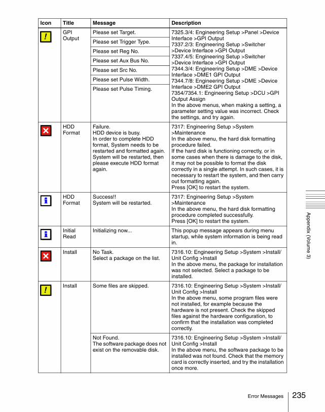
Appendix (V
olume 3)
GPI Output
Please set Target. 7325.3/4: Engineering Setup >Panel >Device Interface >GPI Output7337.2/3: Engineering Setup >Switcher >Device Interface >GPI Output7337.4/5: Engineering Setup >Switcher >Device Interface >GPI Output7344.3/4: Engineering Setup >DME >Device Interface >DME1 GPI Output7344.7/8: Engineering Setup >DME >Device Interface >DME2 GPI Output7354/7354.1: Engineering Setup >DCU >GPI Output AssignIn the above menus, when making a setting, a parameter setting value was incorrect. Check the settings, and try again.
Please set Trigger Type.
Please set Reg No.
Please set Aux Bus No.
Please set Src No.
Please set Pulse Width.
Please set Pulse Timing.
HDD Format
Failure.HDD device is busy.In order to complete HDD format, System needs to be restarted and formatted again.System will be restarted, then please execute HDD format again.
7317: Engineering Setup >System >MaintenanceIn the above menu, the hard disk formatting procedure failed.If the hard disk is functioning correctly, or in some cases when there is damage to the disk, it may not be possible to format the disk correctly in a single attempt. In such cases, it is necessary to restart the system, and then carry out formatting again.Press [OK] to restart the system.
HDD Format
Success!!System will be restarted.
7317: Engineering Setup >System >MaintenanceIn the above menu, the hard disk formatting procedure completed successfully.Press [OK] to restart the system.
Initial Read
Initializing now... This popup message appears during menu startup, while system information is being read in.
Install No Task.Select a package on the list.
7316.10: Engineering Setup >System >Install/Unit Config >InstallIn the above menu, the package for installation was not selected. Select a package to be installed.
Install Some files are skipped. 7316.10: Engineering Setup >System >Install/Unit Config >InstallIn the above menu, some program files were not installed, for example because the hardware is not present. Check the skipped files against the hardware configuration, to confirm that the installation was completed correctly.
Not Found.The software package does not exist on the removable disk.
7316.10: Engineering Setup >System >Install/Unit Config >InstallIn the above menu, the software package to be installed was not found. Check that the memory card is correctly inserted, and try the installation once more.
Icon Title Message Description
235Error Messages

Appendix (V
olume 3)
236
Install All processes have succeeded. 7316.10: Engineering Setup >System >Install/Unit Config >InstallIn the above menu, the installation procedure completed successfully.
Install Error
Target: MENU
Error code:INSTALL_UNCOMPRESS_ERROR
Program file: XXXXX
During software installation, an attempt to uncompress a file failed.
Target: MENU
Error code:Error message received from the Switcher/DME/Panel Processor
Program file: XXXXX
During software installation, an error occurred on the Switcher/DME/Panel Processor.The displayed message is the same as shown in “Error Messages Shown in the Error Information Menu” (page 239).
Install Error
Target: XXXXXError code: XXXXXProgram file: XXXXX
7316.10: Engineering Setup >System >Install/Unit Config >InstallIn the above menu, if an error occurs during installation, this shows:1. Target: Target device for installation2. Error code: Message returned by device3. Program file: Program file name where error
occurredCheck the following, and try the installation once more.•Are you using the correct software package?•Has it been downloaded correctly? (Retry
download)
Target: XXXXXError code: INSTALL_ERR_NOCONFIGNo config file is found.
7316.10: Engineering Setup >System >Install/Unit Config >InstallIn the above menu, when installing, an installation settings file could not be read in correctly.Download another set of installation files, and try the installation once more.
Target: XXXXXError code: INSTALL_ERR_NOPROGRAMNo program file is found.
7316.10: Engineering Setup >System >Install/Unit Config >InstallIn the above menu, when installing, a program file included in the installation settings file could not be read in correctly.Download another set of installation files, and try the installation once more.
Icon Title Message Description
Error Messages

Appendix (V
olume 3)
Internal Error: Data HDD
The user data partition of hard disk drive is damaged, and all data is lost. The hard disk drive needs to be reformatted.Please execute HDD format on Page 7317.
When starting up the menu system, an error was found on the hard disk.In the 7317: Engineering Setup >System > Maintenance menu, execute [HDD Format].
Internal Error: HDD is incorrect
Hard disk is incorrect or not formatted.To format the hard disk, please execute “HDD Format” on Page 7317.
Internal Error: Temporary HDD
The system data partition of hard disk drive is damaged. The hard disk drive needs to be reformatted. Please execute HDD format on Page 7317.Please make sure to save all data in the user data partition of hard disk drive to any other device or media, before reformatted.
Invalid Name
Empty... 2512: Frame Memory >Still >Freeze/StoreIn the above menu, a Store was carried out without specifying a name.Alternatively:71XX: File Menu7171: File >Configure >DirectoryIn the above menu, when renaming a file or creating a directory, the name was not entered. Enter the name correctly.
The file exists already... 2512: Frame Memory >Still >Freeze/StoreIn the above menu, the file name specified for a store operation already exists in the switcher. Specify a different name.
Loading Texture Pattern
Target File: XXXXXFailed to load target bmp file./Illegal Name.This operation is canceled.
7316.9: Engineering Setup >System >Install/Unit Config >Texture PackageIn the above menu, an error occurred when loading a texture file. Delete texture files with an illegal size or illegal file name, then try again.
Target File: XXXXXFailed to load target bmp file./Illegal Size.This operation is canceled.
Make Package
Texture file: XXXXXNot Found.This texture file does not exist on the removable disk.
7316.9: Engineering Setup >System >Install/Unit Config >Texture PackageIn the above menu, when loading an already created texture package, a texture file within the texture package was not found.
This operation is cancelled, because capacity is full.Please clear texture pattern.
7316.9: Engineering Setup >System >Install/Unit Config >Texture PackageIn the above menu, when making a texture package, there was insufficient space on a memory card.
Icon Title Message Description
237Error Messages

Appendix (V
olume 3)
238
Password Password Incorrect 7317.1: Engineering Setup >System >Maintenance >Setup Operation LockIn the above menu, the wrong password was entered.Enter the correct password.
Record Cannot be executed.Maximum number of clips are created.
2523: Frame Memory >Clip >RecordIn the above menu, an attempt was made to execute [Rec Start] but the number of recorded clips had already reached its upper limit.
Rename Files currently used for playback cannot be renamed.
2546: Frame Memory >File >RenameIn the above menu, an attempt was made to execute [Rename], but a movie (clip) currently being played back is included in the selected files.
Set Time/Date
Error: Wrong Format. 7317: Engineering Setup >System >MaintenanceIn the above menu, an incorrect date and time was specified. Specify the date and time correctly.
Warning No Switcher information available.Please confirm “Network Configuration” on Page 7311.
When starting up the menu system, the switcher is not present in the system information. Check the Data LAN connections, and in the 7311: Engineering Setup >System >Network Config menu, retry [Auto Config].
Warning This operation will be cancelled, because the register is locked.Please change the register status to be unlocked first.
6211.1: Effect >Master Timeline >Store >Edit6311.1: Snapshot >Master Snapshot >Store >Edit6411.1: Shotbox >Register >Store >EditIn the above menus, an attempt was made to store in a locked register. Unlock the register before carrying out the store.
Warning (System Config)
Illegal Network Config Information (Page 7311)
When starting up the menu system, if the system information read from the control panel is not correct, one of these messages, that corresponds to the situation appears.Following the message, use 7311: Engineering Setup >System >Network Config or 7312: Engineering Setup >System >System Config to retry the operation.
Illegal Panel Assign Information for Dual Simul Operation (Page 7312)
No Panel Assign Information (Page 7312)
No Switcher Assign Information (Page 7312)
No System Operation Mode Information (Page 7312)
No DME Channel Information
Icon Title Message Description
Error Messages

Appendix (V
olume 3)
Error Messages Shown in the Error Information Menu
If a file transfer related error occurs, the Error Information menu appears to the following error messages.
Error message Error description/measures
[Error] Packet Format Load/save the data again. Still then the message is displayed, contact a Sony service representative.[Error] No Request
[Error] No Request File
[Error] Illegal Host
[Error] Not Supported
[Error] USB Access
[Error] Get File System Info
[Error] Copy Result
[Error] Remove Result
[Error] Move Result
[Error] Make Dir Result
[Error] Path Info
[Error] Dir Operation
[Error] Command Result
[Error] Transfer Result
[Error] Source File Name
[Error] Source File Open
[Error] Source File Read
[Error] Destination File Name
[Error] Destination File Open
[Error] Destination File Read
[Error] Destination File Write
[Error] Illegal Format
[Error] Edit Header
[Error] Local File Access
[Error] FTP Connect
[Error] FTP Busy
[Error] FTP Access
[Error] FTP No Result
[Error] FTP Put Command
[Error] FTP Delete
[Error] FTP Delete Command
[Error] FTP Delete Result
[Error] Control Table No Space
[Error] Control Table Same Name
[Error] No Queue
[Error] Resize BMP
239Error Messages

Appendix (V
olume 3)
240
[Error] Make Vector Load/save the data again. Still then the message is displayed, contact a Sony service representative.[Error] Uncompress
[Error] Compress
[Error] Server Not Respond No reactions are returned from the processor. Check your Data-LAN connections and the power source of the processor.
[Error] No Space There is not sufficient space in the memory card or hard disk.
Error message Error description/measures
Error Messages

Index
Index
AAlarm adjustment 115Autoload function 23Aux bus control enable/disable
152AUX bus remote panel 209AUX delegation button
settings 81shift operation 82
BBackground
transition flip-flop mode 133
Beep 114Border
processing order 137Brightness adjustment 114Button
assignment settings 87operation mode 110
Button assignments 87
CCalibration 115Color correction
switching the function 38Communications status 214Control panel settings 50Cross-point
assign tables 71button shift operation 75settings 71
Cross-point assign tables 78Custom mode 20
DDate and time 39DCU
serial port settings 104
setup 168Default wipe edge softness
138Destination names 108Device
interface 98, 147, 163setup 26
Device interface 163Device management 39Diagnosis 213Disk recorder
settings 185, 186DME setup 157Double-click sensitivity 111
EEditing keyboard 103Effect
settings 107Engineering setup 11, 47,
117, 157, 167, 191, 209Error messages 226
Error Information menu 239
error status/log 226message box 231
Extended VTR 188External
box setting 193
FFader lever operations 134Fade-to-black function 133Formatting a memory card 40Formatting the hard disk 41Function
assignment user preference buttons 87
links 140
GGPI input settings
for control panel 98for DCU 171for DME 164for switcher processor
148GPI output settings
for control panel 101for DCU 177for DME 166for switcher processor
151
IIllegal color limiter 126, 159Initialization
hard disk 41Installation 26
JJoystick sensitivity 111
KKey
auto drop 136memory mode 137priority operation mode
137settings 135
LLink
cross-point buttons 140, 142
key transition 145M/E banks 144
241Index

242
Index
Locking the setup data 42
MMacro
assignment of operation buttons 63
execution mode 112Mask processing order 137Memory card formatting 40Menu shortcut assignment
memory recall button 96user preference buttons
91MKS-8080/8082
setting status 212simple connection 210
Monitor output 161
NNetwork settings 13
OOn-air tally 107Operation mode setting 120Operation settings 106
PParallel
input settings 169output settings 175tally settings 205
Pattern limit 138P-Bus devices
control mode setting 103PGM/PST
logical assignment to M/E 123
Power-on state 20Preset color mix setting 134Primary setting 40
RReference
output setting 128
phase adjustment 120Region
assigning 58Reset 25Reset/initialization 25Resume mode 20Router destination 54Router interface settings 192Router interface/tally setup
191
SSafe title settings 130Screen
saver 114SCU editor panel port 103Serial
port settings 180tally setting 207
Setupfor control panel 50for DCU 168for the whole switcher
system 12locking the data 42
Setup data saving/recalling 21Show key function 136Signal format setting 17Signal input settings
for DME 158for switcher processor
125Signal output settings
for DME 161for switcher processor
127Software
installation 26setting required 28
Source name 108Source signal name 76Split
fader setting 133Spotlighting settings
user texture patterns 31
Start-up state 22Switcher configuration 119Switcher setup 117System
maintenance 39settings 14
TTally
copy settings 203generation settings 200group settings 196
TBC window center position 159
Through mode settings 129Touch panel calibration 115Trackball sensitivity 111Transition
mode 133preview mode setting 132
UUSB driver reloading 41User region setting 123User-defined settings 23
VVertical blanking interval
adjustment 129Video
clip adjustment 129switching settings 132switching timing 120
Video process memory 135VTR
operation button assignment 61
WWipe
settings 135
Index

Index
Wiring settings 197XXPT HOLD button operation
mode 138
243Index

244
Index
Index

The material contained in this manual consists of infor-mation that is the property of Sony Corporation and is intended solely for use by the purchasers of the equip-ment described in this manual.Sony Corporation expressly prohibits the duplication of any portion of this manual or the use thereof for any pur-pose other than the operation or maintenance of the equipment described in this manual without the express written permission of Sony Corporation.

DVS-9000/9000SFSystem (SY)4-136-339-01 (1)
Printed in Japan2009.04 13
©2002
Sony Corporation
Printed on recycled paper.