pressure measurementthe “fluid” in this problem is the air which has a density at the above...
TRANSCRIPT

96
Pressure Measurement
Absolute pressure: It refers to the absolute value of the force per unit
area exerted on the containing wall by a fluid. Gage pressure represents
the difference between the absolute pressure and the local atmospheric
pressure. The absolute pressure may not be negative.
Vacuum represents the amount by which the atmospheric pressure
exceeds the absolute pressure. The vacuum may not be greater than the
local atmospheric pressure.
The three terms are illustrated graphically in Figure(1).
Some Common units of Pressure
1 atmosphere (atm) = 14.696 pounds per square inch absolute
= 1.01325 × 10⁵ newtons per square meter (Pa)
= 2116 pounds-force per square foot (lbf/ft2)
1 N/m2 ≡ 1 pascal (Pa)
1 atmosphere (atm) = 760 millimeters of mercury (mmHg)
1 bar = 105 newtons per square meter (100 kPa)
Fig.(1) Relationship between pressure terms.
1 bar = 105 Pa
1 microbar = 1 dyne per square centimeter
= 2.089 pounds-force per square foot
= 0.1 newton per square meter (0.1 Pa)

07
1 millimeter of mercury (mmHg) = 1333.22 microbar
= 133.322 newtons per square meter
(133.3 Pa)
1 micrometer = 10−6
meters of mercury (μm, microns)
= 10−3
millimeters of mercury (mmHg)
= 0.133322 newtons per square meter=(0.133 Pa)
1 torr ≡ 1 millimeter of mercury (mmHg)
1 inch of mercury = 70.73 pounds-force per square foot
1 inch of water = 5.203 pounds-force per square foot
1 pound per square inch absolute = 6894.76 newtons per square meter
(6.894 kPa)= 0.070307 kilograms-force per square
centimeter (kgf/cm2), [kilopounds
per square centimeter (kp/cm2)]
Mechanical Pressure-Measurement Devices
Mechanical devices offer the simplest means for pressure measurement. It
consists the following measuring devices:
U-Tube Manometer:
The fluid manometer is a widely used device for measurement of fluid
pressures under steady-state and laboratory conditions. Consider the u-
tube manometer shown in figure 1, the difference in pressure between the
unknown pressure p and the atmosphere is determined as a function of the
differential height h.

07
Fig.(1) U-tube manometer
The density of the fluid transmitting the pressure p is ρf , and the density
of the manometer fluid is designated as ρm. A pressure balance of the two
columns dictates that:-
(1)
The sensitivity of the U-tube manometer may be defined as
Sensitivity = h/(p − pa) = h/Δp = 1/(g/gc)(ρm − ρf )
or for a manometer with ρm ρf ,
Sensitivity = 1/ρm(g/gc)
Ex:
A U-tube manometer employs special oil having a specific gravity of 0.82
for the manometer fluid. One side of the manometer is open to local
atmospheric pressure of 29.3 inHg and the difference in column heights is
measured as 20 cm±1.0 mm when exposed to an air source at 25◦C.
Standard acceleration of gravity is present. Calculate the pressure of the
air source in Pascals and its uncertainty.

07
Solution
The manometer fluid has a density of 82 percent of that of water at 25◦C;
so,
ρm = 0.82ρw = (0.82)(996 kg/m3) = 816.7 kg/m3
The local atmospheric pressure is
pa = 29.3 inHg = 9.922 × 10⁴ Pa
The “fluid” in this problem is the air which has a density at the above
pressure and 25◦C (298 K) of
ρf = ρa = p/RT = 9.922 × 10⁴/(287)(298)= 1.16 kg/m
3
For this problem the density is negligible compared to that of the
manometer fluid, but we shall include it anyway. From Eq. (1)
p − pa =( g)h(ρm − ρf ) = 9.807/1(0.2)(816.7 − 1.16)= 1600 Pa
or p = 1600 + 9.922 × 104 = 1.0082 × 10
5 Pa
The uncertainty of the column height measurement is
1mm/(20cm×10mm/cm) = 1/200= 0.5 %
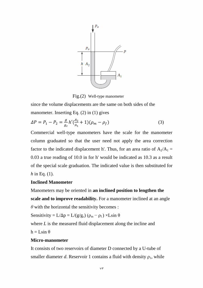
Well-type manometer:
A well-type manometer operates in the same manner as the U-tube
manometer, except that the construction is as shown in Fig. 6.4. In this
case the pressure balance of Eq. (1) still yields
p − pa = g/gc h(ρm − ρf )
The well-type manometer is filled to a certain level at zero-pressure
differential conditions. A measurement is then made of the displacement
of the small column from this zero level. Designating this displacement
by h', we have
(2)
07
Fig.(2) Well-type manometer
since the volume displacements are the same on both sides of the
manometer. Inserting Eq. (2) in (1) gives
(3)
Commercial well-type manometers have the scale for the manometer
column graduated so that the user need not apply the area correction
factor to the indicated displacement h'. Thus, for an area ratio of A2/A1 =
0.03 a true reading of 10.0 in for h' would be indicated as 10.3 as a result
of the special scale graduation. The indicated value is then substituted for
h in Eq. (1).
Inclined Manometer
Manometers may be oriented in an inclined position to lengthen the
scale and to improve readability. For a manometer inclined at an angle
θ with the horizontal the sensitivity becomes :
Sensitivity = L/Δp = L/(g/gc) (ρm − ρf ) ×Lsin θ
where L is the measured fluid displacement along the incline and
h = Lsin θ
Micro-manometer
It consists of two reservoirs of diameter D connected by a U-tube of
smaller diameter d. Reservoir 1 contains a fluid with density ρ1, while
07
reservoir 2 contains a fluid having a density ρ2. The assembly is subjected
to a pressure differential Δp. The sensitivity may be derived
3
(4)
When D d and the difference in the two fluid densities is small, a very
large sensitivity can result.
Dead-Weight Tester
The dead-weight tester is a device used for balancing a fluid pressure
with a known weight. Typically, it is a device used for static calibration
of pressure gages. Consider the schematic in Fig. (3). The apparatus is
set up for calibration of the pressure gage G. The chamber and cylinder of
the tester are filled with a clean oil . The gage to be tested is installed and
the piston inserted in the cylinder. The pressure exerted on the fluid by
the piston is now transmitted to the gage when the valve is opened. This
pressure may be varied by adding weights to the piston. The viscous
friction between the piston and the cylinder in the axial direction may be
substantially reduced by rotating the piston-weight assembly while the
measurement is taken. As the pressure is increased, it may be necessary
to advance the plunger to account for the compression of the oil and any
entrapped gases in the apparatus. The accuracies of dead-weight testers
are limited by two factors:
(1) The friction between the cylinder and the piston.
(2) The uncertainty in the area of the piston.
The friction is reduced by rotation of the piston and use of long enough
surfaces to ensure negligible flow of oil through the annular space
between the piston and the cylinder. The area upon which the weight
force acts is not the area of the piston or the area of the cylinder; it is

07
some effective area between these two which depends on the clearance
spacing and the viscosity of the oil. The smaller the clearance, the more
closely the effective area will approximate the cross-sectional area of the
piston.
Fig.(3) Schematic of a dead-weight tester.
It can be shown that the percentage error due to the clearance varies
according to
(5)
where
ρ = density of the oil
Δp = pressure differential on the cylinder
b = clearance spacing
μ = viscosity
D = piston diameter
L = piston length
09
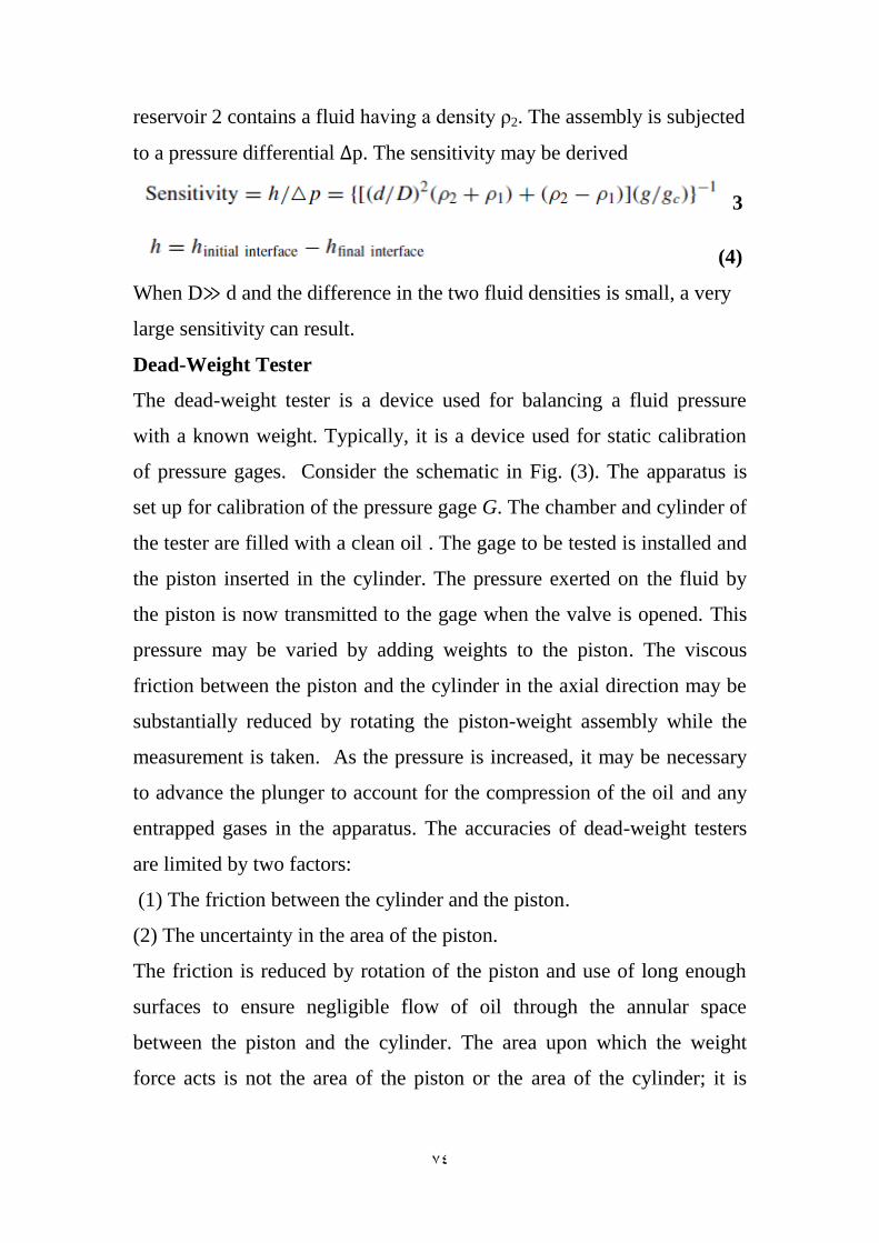
Bourdon-Tube Pressure Gage
Bourdon-tube pressure gages enjoy a wide range of application where
consistent, inexpensive measurements of static pressure are desired. They
are commercially available in many sizes (1- to 16-in diameter) and
accuracies. The construction of a bourdon-tube gage is shown in Figure
(4). The bourdon tube itself is usually an elliptical cross-sectional tube
having a C-shape configuration. When the pressure is applied to the
inside of the tube, an elastic deformation results, which, ideally, is
proportional to the pressure. The degree of linearity depends on the
quality of the gage. The end of the gage is connected to a spring-
loaded linkage, which amplifies the displacement and transforms it to
an angular rotation of the pointer.
Fig.(4) Schematic of a bourdon-tube pressure gage.
Electrical-resistance strain gages may also be installed on the bourdon
tube to sense the elastic deformation. A proprietary design of digital
pressure transducers based upon piezo-resistance strain gage response
00
claims an accuracy of 0.02 percent of full scale and is available in full-
scale ranges from l0 to 10,000 psia.
Diaphragm and Bellows Gages
Diaphragm and bellows gages represent similar types of elastic
deformation devices useful for many pressure-measurement applications.
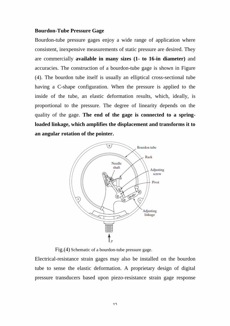
Diaphragm Gages
Consider first the flat diaphragm subjected to the differential pressure
p1−p2, as shown in Figure (5). The diaphragm will be deflected in
accordance with this pressure differential and the deflection sensed by an
appropriate displacement transducer.
Fig.(5) Schematic of a diaphragm gage.
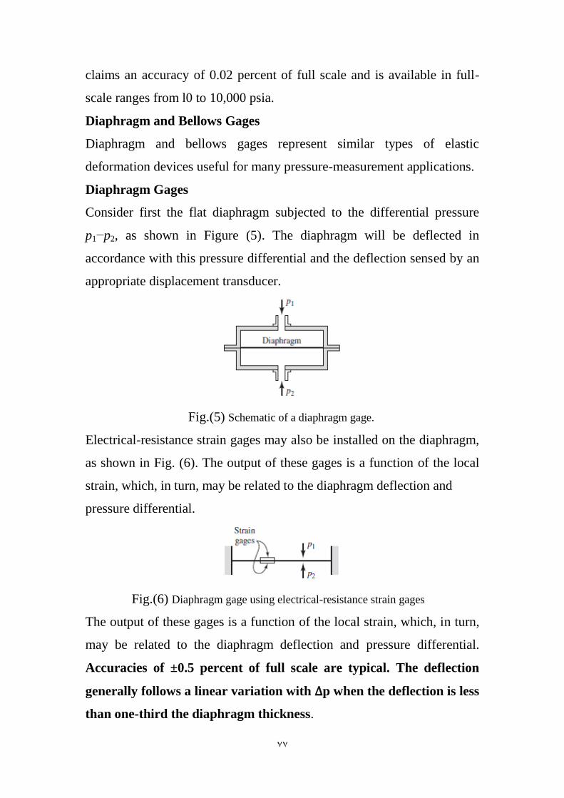
Electrical-resistance strain gages may also be installed on the diaphragm,
as shown in Fig. (6). The output of these gages is a function of the local
strain, which, in turn, may be related to the diaphragm deflection and
pressure differential.
Fig.(6) Diaphragm gage using electrical-resistance strain gages
The output of these gages is a function of the local strain, which, in turn,
may be related to the diaphragm deflection and pressure differential.
Accuracies of ±0.5 percent of full scale are typical. The deflection
generally follows a linear variation with Δp when the deflection is less
than one-third the diaphragm thickness.

07
Capacitive Transducer
The deflection of a diaphragm under pressure may be sensed by a
capacitance variation, as shown in Figure(7). Such pressure pickups are
well suited for dynamic measurements since the natural frequency of
diaphragms can be rather high. The capacitance pickup, however,
involves low sensitivity, and special care must be exerted in the
construction of readout circuitry.
Fig.(7)Capacitance pressure gage
Bellow Gages
The bellows gage is depicted schematically in Figure(8). A differential
pressure force causes a displacement of the bellows, which may be
converted to an electrical signal or undergo a mechanical amplification to
permit display of the output on an indicator dial. The bellows gage is
generally unsuitable for transient measurements because of the
larger relative motion and mass involved. The diaphragm gage, on
the other hand, which may be quite stiff, involves rather small
displacements and is suitable for high-frequency pressure
measurements.

06
Fig.(8) Schematic of a bellows pressure gage
Differential Pressure Gage
Differential pressure gage is shown in Figure(9). Commercial models of
this type of gage permit measurement of pressures as low as 0.00035 psi
(0.25 Pa). The natural frequency of a circular diaphragm fixed at its
perimeter is given by
(6)
where E = modulus of elasticity, psi or Pa
t = thickness, in or m
a = radius of diaphragm, in or m
ρ = density of material, lbm/in3 or kg/m3
gc = dimensional conversion constant = 385.9 lbm · in/lbf · s2 or 1.0 kg ·
m/N · s2
μ = Poisson’s ratio
77
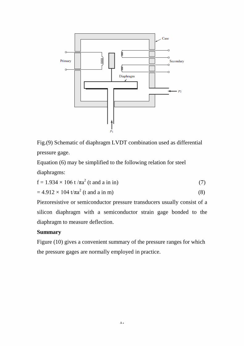
Fig.(9) Schematic of diaphragm LVDT combination used as differential
pressure gage.
Equation (6) may be simplified to the following relation for steel
diaphragms:
f = 1.934 × 10⁶ t /πa2 (t and a in in) (7)
= 4.912 × 10⁴ t/πa2 (t and a in m) (8)
Piezoresistive or semiconductor pressure transducers usually consist of a
silicon diaphragm with a semiconductor strain gage bonded to the
diaphragm to measure deflection.
Summary
Figure (10) gives a convenient summary of the pressure ranges for which
the pressure gages are normally employed in practice.

77
Fig.(10)Summary of applicable range of pressure gages.

77
Dynamic Response Considerations
The fluctuating pressure has a frequency of ω and an amplitude of p0 and
is impressed on the tube of length L and radius r. At the end of this tube is
a chamber of volume V as shown in figure (11)where the connection to
the pressure-sensitive transducer is made. If the conventional formula for
laminar friction resistance in the tube flow is used to represent this
friction, the resulting expression for the pressure-amplitude ratio is:
|
|
[ (
) ]
(
)
(9)
In this equation p is the amplitude of the pressure signal impressed on the
transducer. The natural frequency ωn is given by
(10)
and the damping ratio ζ is
√
(11)
Fig.(11)
In the above formulas c represents the velocity of sound in the fluid, μ is
the dynamic viscosity of the fluid, and ρ is the fluid density. The phase
angle for the pressure signal is
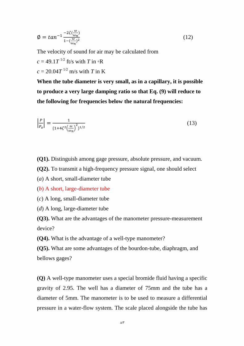
77
(12)
The velocity of sound for air may be calculated from
c = 49.1T 1/2
ft/s with T in ◦R
c = 20.04T 1/2
m/s with T in K
When the tube diameter is very small, as in a capillary, it is possible
to produce a very large damping ratio so that Eq. (9) will reduce to
the following for frequencies below the natural frequencies:
|
|
(
)
(13)
(Q1). Distinguish among gage pressure, absolute pressure, and vacuum.
(Q2). To transmit a high-frequency pressure signal, one should select
(a) A short, small-diameter tube
(b) A short, large-diameter tube
(c) A long, small-diameter tube
(d) A long, large-diameter tube
(Q3). What are the advantages of the manometer pressure-measurement
device?
(Q4). What is the advantage of a well-type manometer?
(Q5). What are some advantages of the bourdon-tube, diaphragm, and
bellows gages?
(Q) A well-type manometer uses a special bromide fluid having a specific
gravity of 2.95. The well has a diameter of 75mm and the tube has a
diameter of 5mm. The manometer is to be used to measure a differential
pressure in a water-flow system. The scale placed alongside the tube has

77
no correction factor for the area ratio of the manometer. Calculate the
value of a factor that may be multiplied by the manometer reading in
inches to find the pressure differential in pounds per square inch.
A2=1.95×10⁻⁵
m2 , A1=4.41×10
-3, 2.95
1
Or the factor is 1.95N/m3
(Q) AU-tube manometer uses tubes of 0.250 and 0.500 in diameters for
the two legs. When subjected to a certain pressure, the difference in
height of the two fluid columns is 10.0 inHg. What would have been the
reading if both tubes were the same diameter? The measurement is
performed on air.
Solution:
The reading would be the same. 10 in. Hg
(Q) A manometer uses a fluid having a specific gravity of 1.85. The
sensing fluid is water. What is the pressure difference when the difference
in heights of the columns is 5.0 in? Assume that both legs of the
manometer are filled with water.
Solution:
Δ ( )
77
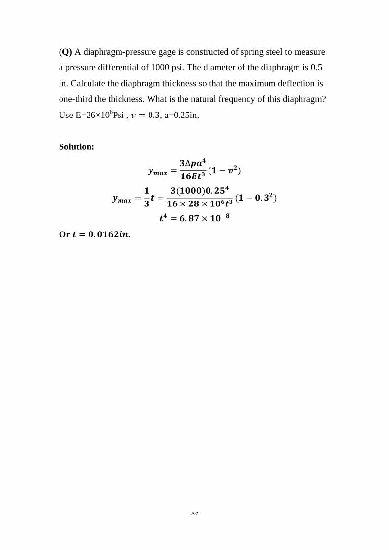
(Q) A diaphragm-pressure gage is constructed of spring steel to measure
a pressure differential of 1000 psi. The diameter of the diaphragm is 0.5
in. Calculate the diaphragm thickness so that the maximum deflection is
one-third the thickness. What is the natural frequency of this diaphragm?
Use E=26×106Psi , , a=0.25in,
Solution:
Or .