prepared for: abc sample - arc flash safety training
TRANSCRIPT

(502) 716-7073 Office (502) 371-6300 Fax
3018 Eastpoint Parkway Louisville, KY 40223
www.e-hazard.com [email protected]
Taking the Flash Out of Electrical Safety
October 3, 2017
Arc Flash Study
Prepared for:
ABC
City, State
Prepared by:
John D. Aeiker, PE, CSP
Consultant
CONTENTS Arc Flash Study Overview
Incident Energy Summary Report
Equipment Evaluation Report
PPE Poster
Arc Flash Model Drawing
SAMPLE
October 3, 2017 2
(502) 716-7073 Office (502) 371-6300 Fax
3018 Eastpoint Parkway Louisville, KY 40223
www.e-hazard.com [email protected]
October 3, 2017
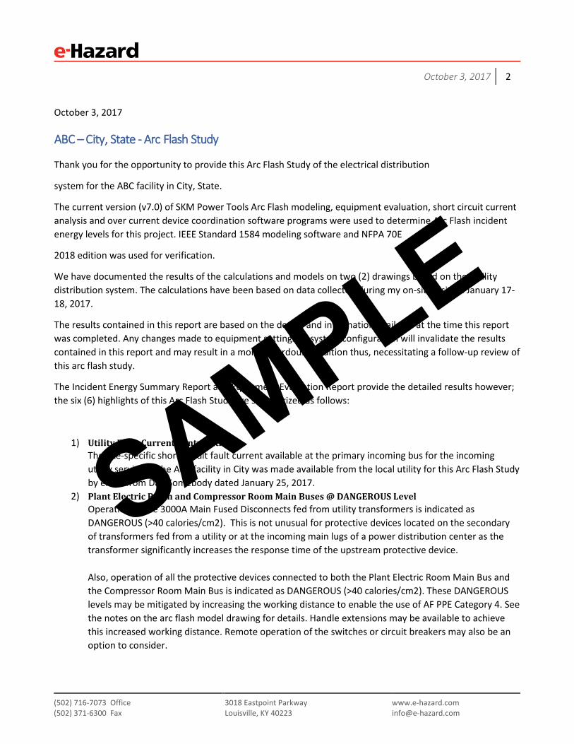
ABC – City, State - Arc Flash Study
Thank you for the opportunity to provide this Arc Flash Study of the electrical distribution
system for the ABC facility in City, State.
The current version (v7.0) of SKM Power Tools Arc Flash modeling, equipment evaluation, short circuit current analysis and over current device coordination software programs were used to determine Arc Flash incident energy levels for this project. IEEE Standard 1584 modeling software and NFPA 70E
2018 edition was used for verification.
We have documented the results of the calculations and models on two (2) drawings based on the facility distribution system. The calculations have been based on data collected during my on-site visit on January 17-18, 2017.
The results contained in this report are based on the design and information available at the time this report was completed. Any changes made to equipment settings or system configuration will invalidate the results contained in this report and may result in a more hazardous condition thus, necessitating a follow-up review of this arc flash study.
The Incident Energy Summary Report and Equipment Evaluation Report provide the detailed results however; the six (6) highlights of this Arc Flash Study are summarized as follows:
1) Utility Fault Current ContributionThe site-specific short circuit fault current available at the primary incoming bus for the incomingutility service to the ABC facility in City was made available from the local utility for this Arc Flash Studyby email from Dan Somebody dated January 25, 2017.
2) Plant Electric Room and Compressor Room Main Buses @ DANGEROUS LevelOperation of the 3000A Main Fused Disconnects fed from utility transformers is indicated asDANGEROUS (>40 calories/cm2). This is not unusual for protective devices located on the secondaryof transformers fed from a utility or at the incoming main lugs of a power distribution center as thetransformer significantly increases the response time of the upstream protective device.
Also, operation of all the protective devices connected to both the Plant Electric Room Main Bus andthe Compressor Room Main Bus is indicated as DANGEROUS (>40 calories/cm2). These DANGEROUSlevels may be mitigated by increasing the working distance to enable the use of AF PPE Category 4. Seethe notes on the arc flash model drawing for details. Handle extensions may be available to achievethis increased working distance. Remote operation of the switches or circuit breakers may also be anoption to consider.
SAMPLE

October 3, 2017 3
(502) 716-7073 Office (502) 371-6300 Fax
3018 Eastpoint Parkway Louisville, KY 40223
www.e-hazard.com [email protected]
3) System MiscoordinationThe Incident Energy Summary Report indicates a few areas of over current device miscoordination, seethe (*N5) notations in the arc flash summary report. In a few cases, subpanel branch breakers arecoordinated to the bus duct fused disconnects bypassing the subpanel main breakers.
In an industrial power system, miscoordination is not an uncommon situation to find and it typicallyworks in your favor relative to arc flash as the speed of the upstream protective device reduces theincident energy exposure. These upstream protective devices function in this manner only in anoverload condition. As we understand the system is reliable and functions well, our recommendationis to leave these devices and their settings in their current state. While a detailed system analysiscould be considered, it should be noted that this power system device coordination analysis couldconsume significant engineering and field monitoring cost.
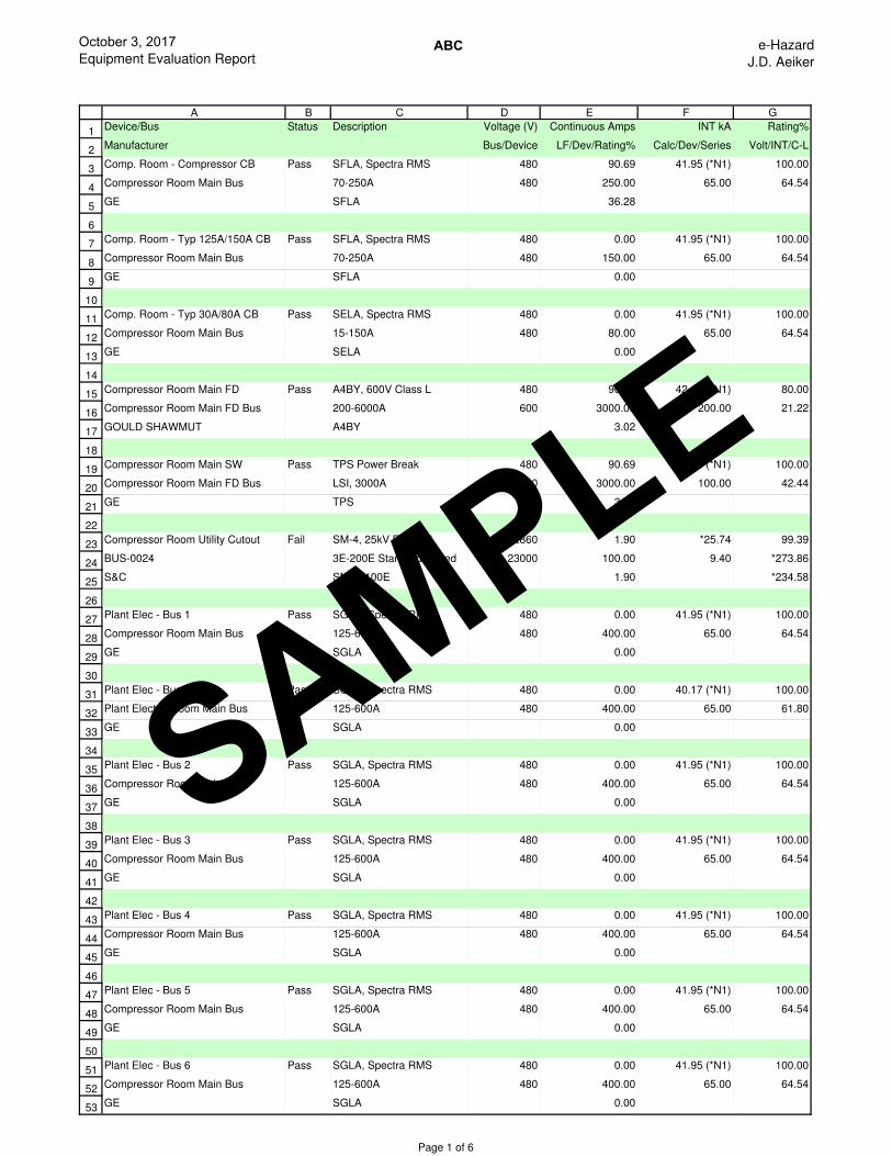
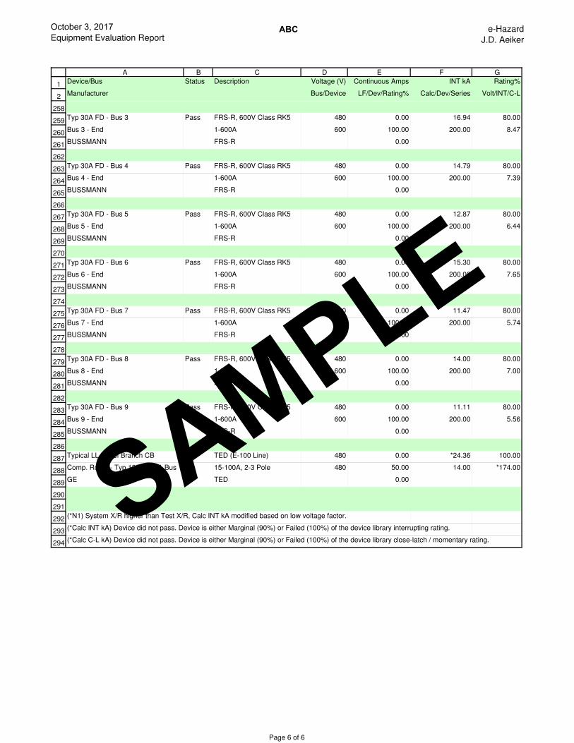
4) Equipment Evaluation ReportThe Equipment Evaluation Report indicates a few failures or marginal ratings. These are primarily intwo areas of over current device ratings in the Device Evaluation Summary Reports. One area is theShort Circuit Current Available ratings for a device > 80% SCCA ratings and the other is related toconnected load to the device > 80% for continuous load ratings.
a. In the case of the available short circuit current ratings, these devices are continuous dutyrated and thus they are suitable for the service as designed and intended. This is a softwaredefault value based on the NEC and in this case is not applicable to your system.
b. The second area is relative to connected load greater than 80% and 100%. The softwarecannot determine the real horsepower of a particular motor and assumes it to be 100%loaded.It cannot determine true loading of multiple motors operated in a lead / lag configuration. Itcalculates to 100% load on every device connected. It cannot calculate diversity of loads perthe NEC. This is the only reason you will find a marginal rating on a device due to loading > 80%or a failure rating on a device due to loading > 100%.
5) Equipment LabelingThe switchboard and motor control center (MCC) sections will be labeled to the actual incident energylevels per the requirements of IEEE 1584 and NFPA 70E for testing, troubleshooting and interactingwith the device with exposed energized parts. All disconnects that could require maintenance, testingor troubleshooting will be labeled to the requirements of NFPA 70E 130.5(H); extracted text fromprovided next.
NFPA 70E, 2015 Edition (Pg. 28)130.5 (H) Equipment Labeling. Electrical equipment such as switchboards, panel boards, industrial controlpanels, meter socket enclosures, and motor control centers that are in other than dwelling units and thatare likely to require examination, adjustment, servicing, or maintenance while energized shall be field-marked with a label containing all the following information:
(1) Nominal system voltage(2) Arc flash boundary(3) At least one of the following:
a. Available incident energy and the corresponding working distance, or the arc flashPPE category in Table 130.7(C)(15)(A)(b) or Table 130.7(C)(15)(B)for theequipment, but not both
SAMPLE

October 3, 2017 4
(502) 716-7073 Office (502) 371-6300 Fax
3018 Eastpoint Parkway Louisville, KY 40223
www.e-hazard.com [email protected]
b. Minimum arc rating of clothingc. Site-specific level of PPE
Exception: Labels applied prior to September 30, 2011 are acceptable if they contain the available incident energy or required level of PPE.
The method of calculating and the data to support the information for the label shall be documented. Where the review of the arc flash hazard risk assessment identifies a change that renders the label inaccurate, the label shall be updated.
The owner of the electrical equipment shall be responsible for the documentation, installation, and maintenance of the field-marked label.
6) Operation of Electrical EquipmentThe motor control centers and distribution panels are typical lockout points. The calculated energylevels as indicated on the drawings are often in excess of 1.2 calories/cm2 and as such would requiresome level of arc rated PPE.
NFPA 70E, 2018 Edition (Pg. 24)130.2 Electrically Safe Working Conditions(a) Energized Work(4) Normal Operation. Normal operation of electric equipment shall be permitted where all of thefollowing conditions are satisfied:
1) The equipment is properly installed.2) The equipment is properly maintained.3) The equipment doors are closed and secured.4) All equipment covers are in place and secured.5) There is no evidence of impending failure.
Informational Note: The phrase properly installed means that the equipment is installed in accordance with applicable industry codes and standards and the manufacturer’s recommendations. The phrase properly maintained means that the equipment has been maintained in accordance with the manufacturer’s recommendations and applicable industry codes and standards. The phrase evidence of impending failure means that there is evidence such as arcing, overheating, loose or bound equipment parts, visible damage, or deterioration.
SAMPLE

October 3, 2017 5
(502) 716-7073 Office (502) 371-6300 Fax
3018 Eastpoint Parkway Louisville, KY 40223
www.e-hazard.com [email protected]
NFPA 70E, 2018 Edition (Pg. 35) Table 130.7(C) (15) (A)(a) Arc Flash Hazard Identification for Alternating Current (ac) and Direct Current (dc) Systems
Task Equipment Condition* Arc Flash PPE Required
… Normal operation of a circuit breaker (CB), switch, contactor, or starter
All of the following:
The equipment is properly installed The equipment is properly maintained All equipment doors are closed and secured All equipment covers are in place and secured There is no evidence of impending failure
No
One or more of the following: The equipment is not properly installed The equipment is not properly maintained Equipment doors are open or not secured Equipment covers are off or not secured There is evidence of impending failure
Yes
NFPA 70E makes it very clear the determination of this condition can only be made by the responsible person in charge of the facility. If the facility has evidence and documentation as per the requirements of NFPA 70E 205.3, 205.4 and 210.5 that all five conditions are met, then no arc rated PPE would be required to operate disconnects with the doors properly closed and latched. "In our experience, it is very rare that equipment is maintained to the exact specifications of the manufacturer”. For reference see NFPA extracts listed below.
A safer approach could be taken. Other facilities with similar situations provide an appropriate Arc Rated switchers coat, face shield and leather gloves in each of the MCC rooms and then instruct the task qualified workers when performing the lock out procedure to wear the coat, hard hat, face shield and gloves to interact with the disconnect in question. If this approach is taken, the under layer clothing shall be 100% natural fiber non-melting clothing per NFPA 70E. After the disconnect switch is operated to the “off” position, then lock out procedures can be performed without any arc rated PPE.
NFPA 70E, 2018 Edition (Pg. 44 & 45) 205.3 General Maintenance Requirements. Electrical equipment shall be maintained in accordance with manufacturers’ instructions or industry consensus standards to reduce the risk associated with failure. The equipment owner or the owner’s designated representative shall be responsible for maintenance of the electrical equipment and documentation.
Informational Note: Common industry practice is to apply test or calibration decals to equipment to indicate the test or calibration date and overall condition of equipment that has been tested and maintained in the field. These decals provide the employee immediate indication of last maintenance date and if the tested device or system was found acceptable on the date of test. This local information can assist the employee in the assessment of overall electrical equipment maintenance status.
SAMPLE

October 3, 2017 6
(502) 716-7073 Office (502) 371-6300 Fax
3018 Eastpoint Parkway Louisville, KY 40223
www.e-hazard.com [email protected]
205.4 Overcurrent Protective Devices. Overcurrent protective devices shall be maintained in accordance with the manufacturers’ instructions or industry consensus standards. Maintenance, tests, and inspections shall be documented.
210.5 Protective Devices. Protective devices shall be maintained to adequately withstand or interrupt available fault current.
Informational Note: Improper or inadequate maintenance can result in increased opening time of the overcurrent protective device, thus increasing the incident energy.
The calculations in this study and resultant incident energy levels are based upon the overcurrent devices (overcurrent relays, circuit breakers, and fused disconnects) operating as designed and being properly maintained. Maintenance intervals should be based on the manufacturer’s recommendations or industry consensus testing standards. This is typically a 3 to 5 year interval based on the conditions of the equipment. The InterNational Electrical Testing Association (NETA) provides guidance documents for adjusting these intervals based on location conditions.
It is important to note that in many cases, changing the trip settings of the equipment in place in the facility is relatively simple to do. Full-function circuit breakers and time overcurrent relay devices often have adjustable long-time, short-time and instantaneous (LSI) trip units that provide the unique ability to modify or change the trip settings with a small screwdriver. As any changes to the equipment settings may have a significant impact on the incident energy levels found in the electrical system, the facility should have a change management process in place to maintain the settings as found for this Arc Flash Study. Any change to the site distribution system or a change by the utility relative to your incoming service fault current could necessitate a review of this arc flash study.
Annex H of NFPA 70E provides guidance for a clothing system to 12 calories/cm2 and as such on all the model drawings anytime there is a PPE Category 3 situation it will be indicated as such with the specific calories/cm2 exposure. This can help you if your clothing supplier is providing 12 calories/cm2 clothing. This needs to be verified to what level of protection your PPE uniform clothing provides. This can be your decision after verification of the ATPV of the clothing supplied, documented and communicated to the affected personnel. Layering of Arc rated clothing is allowed as long as it has been tested as a system. This information is available on the clothing manufacturers’ websites as well as on ArcWear.com. As an example, Westex has tested their Indura Ultrasoft shirt with their T-shirt (typical rental company provided material) and the combination achieves 20 calories/cm2. Tyndale’s 9 calories/cm2 shirt has been tested with various other 4 calories/cm2 T-shirts achieving slightly higher overall results when used together.
Any exposures greater than PPE Category 1 (> 4 calories/cm2) requires the use of an arc rated face shield and balaclava or an arc rated face shield hood assembly.
NFPA 70E requires the arc flash study to be reviewed every five years. If the utility contacts you for a service interruption, ask the question for what purpose. If they are upgrading the transmission line or transmission / distribution transformers, this is your indication to find out what the change will be to your incoming fault current and relay clearing times which can affect the arc flash calculations.
SAMPLE

October 3, 2017 7
(502) 716-7073 Office (502) 371-6300 Fax
3018 Eastpoint Parkway Louisville, KY 40223
www.e-hazard.com [email protected]
If the utility has not changed anything relative to your incoming service fault current and you have not changed anything in your distribution system on site, then the review can be a very simple process of noting this fact every 5 years. A verification from the utility of the utility information found on the arc flash study document and also contained on the USB drive is all that would be required.
NFPA 70E requires initial qualified training and re-training every three years for your qualified electrical workers. We typically recommend electrical safety training after the labeling activity as this can provide a customized session for your specific equipment and what the labels require as far as proper work practices.
Within the documentation binder for this study are copies of all the associated information; this summary report, the one-line drawings from SKM, the Incident Energy Summary Report, and the Equipment Evaluation Report. All of the relative files in PDF, native Microsoft Office format and native SKM format are provided on an USB drive for file retention. It is recommended that these files be retained in a secure location within your organization. e-Hazard also retains the files backed up to a “secured cloud service”.
I keep an exact duplicate of the documentation binder in my office so if there is ever a question, we can both look at the exact same piece of information at any time in the future. If I should be traveling, I have all the files on my laptop with me.
Please call John Aeiker, 251-581-1492 for any additional clarification relative to this report.
Thank you,
SAMPLE

October 3, 2017 Incident Energy Summary Report
ABC e-Hazard
J.D. Aeiker
1
2
3
4
5
6
7
8
9
10
11
12
13
14
15
16
17
18
19
20
21
22
23
24
25
26
27
28
29
30
31
32
33
34
35
A B C D E F G H I J K L M N O P
Bus Name Protective Bus Bus Bus Prot Dev Prot Dev Trip/ Breaker Ground Equip Gap Arc Working Incident PPE Level
Device kV Bolted Arcing Bolted Arcing Delay Opening Type (mm) Flash Distance Energy
Name Fault Fault Fault Fault Time Time/Tol Boundary (in) (cal/cm2)
(kA) (kA) (kA) (kA) (sec.) (sec.) (in)
Bus 1 - Begin Plant Elec - Bus 1 0.48 26.90 15.27 26.90 15.27 0.025 0.000 Yes PNL 25 19 18 1.3 Level 1
Bus 1 - End Plant Elec - Bus 1 0.48 15.76 9.67 15.76 9.67 0.025 0.000 Yes PNL 25 14 18 0.80 Level 0
Bus 10 - Begin Plant Elec - Bus 10 0.48 35.03 19.14 35.03 19.14 0.025 0.000 Yes PNL 25 22 18 1.7 Level 1
Bus 10 - End Plant Elec - Bus 10 0.48 27.32 15.47 27.32 15.47 0.025 0.000 Yes PNL 25 19 18 1.3 Level 1
Bus 2 - Begin Plant Elec - Bus 2 0.48 32.38 17.89 32.38 17.89 0.025 0.000 Yes PNL 25 21 18 1.6 Level 1
Bus 2 - End Plant Elec - Bus 2 0.48 17.66 10.66 17.66 10.66 0.025 0.000 Yes PNL 25 15 18 0.89 Level 0
Bus 3 - Begin Plant Elec - Bus 3 0.48 26.90 15.27 26.90 15.27 0.025 0.000 Yes PNL 25 19 18 1.3 Level 1
Bus 3 - End Plant Elec - Bus 3 0.48 16.94 10.29 16.94 10.29 0.025 0.000 Yes PNL 25 15 18 0.86 Level 0
Bus 4 - Begin Plant Elec - Bus 4 0.48 24.32 14.01 24.32 14.01 0.025 0.000 Yes PNL 25 18 18 1.2 Level 0
Bus 4 - End Plant Elec - Bus 4 0.48 14.79 9.16 14.79 9.16 0.025 0.000 Yes PNL 25 14 18 0.75 Level 0
Bus 5 - Begin Plant Elec - Bus 5 0.48 21.51 12.62 21.51 12.62 0.025 0.000 Yes PNL 25 17 18 1.1 Level 0
Bus 5 - End Plant Elec - Bus 5 0.48 12.87 8.14 12.87 8.14 0.025 0.000 Yes PNL 25 13 18 0.66 Level 0
Bus 6 - Begin Plant Elec - Bus 6 0.48 19.24 11.47 19.24 11.47 0.025 0.000 Yes PNL 25 16 18 0.96 Level 0
Bus 6 - End Plant Elec - Bus 6 0.48 15.30 9.43 15.30 9.43 0.025 0.000 Yes PNL 25 14 18 0.78 Level 0
Bus 7 - Begin Plant Elec - Bus 7 0.48 17.92 10.79 17.92 10.79 0.025 0.000 Yes PNL 25 15 18 0.90 Level 0
Bus 7 - End Plant Elec - Bus 7 0.48 11.47 7.37 11.47 7.37 0.025 0.000 Yes PNL 25 12 18 0.60 Level 0
Bus 8 - Begin Plant Elec - Bus 8 0.48 17.92 10.79 17.92 10.79 0.025 0.000 Yes PNL 25 15 18 0.90 Level 0
Bus 8 - End Plant Elec - Bus 8 0.48 14.00 8.74 14.00 8.74 0.025 0.000 Yes PNL 25 13 18 0.72 Level 0
Bus 9 - Begin Plant Elec - Bus 9 0.48 17.07 10.36 17.07 10.36 0.025 0.000 Yes PNL 25 15 18 0.86 Level 0
Bus 9 - End Plant Elec - Bus 9 0.48 11.11 7.18 11.11 7.18 0.025 0.000 Yes PNL 25 12 18 0.58 Level 0
BUS-0003 Compressor Room Utility
Cutout
22.86 22.95 22.95 22.94 22.94 0.017 0.000 Yes SWG 153 76 36 5.4 Level 2 (*N11) (*N21)
Comp. Room - Typ
125A/150A Bus
Comp. Room - Typ
125A/150A CB
0.48 24.36 14.03 24.36 14.03 0.025 0.000 Yes PNL 25 18 18 1.2 Level 0
Comp. Room - Typ
30A/80A Bus
Comp. Room - Typ
30A/80A CB
0.48 18.63 11.16 18.63 11.16 0.025 0.000 Yes PNL 25 15 18 0.93 Level 0
Compressor Room Main
Bus
Compressor Room Utility
Cutout
0.48 39.77 18.13 39.24 17.88 2 0.000 Yes PNL 25 306 18 125 Dangerous! (*N3)
(*N5) (*N9) (*N21)
Compressor Room Main
FD Bus
Compressor Room Utility
Cutout
0.48 39.95 18.20 39.42 17.96 2 0.000 Yes PNL 25 307 18 125 Dangerous! (*N3)
(*N9) (*N21)
Furnace 701 Bus Plant Elec - Furnace 701
CB
0.48 20.04 11.87 19.19 11.37 0.025 0.000 Yes PNL 25 16 18 1.00 Level 0
Furnace 702 Bus Plant Elec - Furnace 702
CB
0.48 17.28 10.46 16.44 9.96 0.025 0.000 Yes PNL 25 15 18 0.87 Level 0
Furnance 701 Heater Plant Elec - Furnace 701
CB
0.24 12.09 5.23 11.58 5.01 2 0.000 Yes PNL 25 135 18 33 Level 4 (*N9)
Furnance 702 Heater Plant Elec - Furnace 702
CB
0.24 11.55 5.06 10.99 4.82 2 0.000 Yes PNL 25 132 18 31 Level 4 (*N9)
Plant Electric Main FD
Bus
Plant Electric Utility
Cutouts
0.48 38.11 20.56 36.38 19.63 1.838 0.000 Yes PNL 25 310 18 128 Dangerous! (*N21)
Plant Electric Room
Main Bus
Plant Electric Utility
Cutouts
0.48 37.95 20.49 36.22 19.55 1.856 0.000 Yes PNL 25 311 18 128 Dangerous! (*N5)
(*N21)
Page 1 of 5
SAMPLE

October 3, 2017 Incident Energy Summary Report
ABC e-Hazard
J.D. Aeiker
1
2
3
4
A B C D E F G H I J K L M N O P
Bus Name Protective Bus Bus Bus Prot Dev Prot Dev Trip/ Breaker Ground Equip Gap Arc Working Incident PPE Level
Device kV Bolted Arcing Bolted Arcing Delay Opening Type (mm) Flash Distance Energy
Name Fault Fault Fault Fault Time Time/Tol Boundary (in) (cal/cm2)
(kA) (kA) (kA) (kA) (sec.) (sec.) (in)
36
37
38
39
40
41
42
43
44
45
46
47
48
49
50
51
52
53
54
55
56
57
58
SSR Compressors Comp. Room -
Compressor CB
0.48 29.54 16.54 29.02 16.25 0.025 0.000 Yes PNL 25 20 18 1.4 Level 1
Typ 100A Load - Bus 1 Typ 100A FD - Bus 1 0.48 10.48 6.83 10.48 6.83 0.004 0.000 Yes PNL 25 4 18 0.09 Level 0
Typ 100A Load - Bus 10 Typ 100A FD - Bus 10 0.48 15.03 9.29 15.03 9.29 0.004 0.000 Yes PNL 25 5 18 0.13 Level 0
Typ 100A Load - Bus 2 Typ 100A FD - Bus 2 0.48 11.35 7.31 11.35 7.31 0.004 0.000 Yes PNL 25 4 18 0.10 Level 0
Typ 100A Load - Bus 3 Typ 100A FD - Bus 3 0.48 11.01 7.12 11.01 7.12 0.004 0.000 Yes PNL 25 4 18 0.10 Level 0
Typ 100A Load - Bus 4 Typ 100A FD - Bus 4 0.48 10.02 6.57 10.02 6.57 0.004 0.000 Yes PNL 25 4 18 0.09 Level 0
Typ 100A Load - Bus 5 Typ 100A FD - Bus 5 0.48 9.08 5.13 9.08 5.13 0.008 0.000 Yes PNL 25 5 18 0.13 Level 0 (*N3)
Typ 100A Load - Bus 6 Typ 100A FD - Bus 6 0.48 10.22 6.68 10.22 6.68 0.004 0.000 Yes PNL 25 4 18 0.09 Level 0
Typ 100A Load - Bus 7 Typ 100A FD - Bus 7 0.48 8.35 4.78 8.35 4.78 0.008 0.000 Yes PNL 25 5 18 0.12 Level 0 (*N3)
Typ 100A Load - Bus 8 Typ 100A FD - Bus 8 0.48 9.62 6.34 9.62 6.34 0.004 0.000 Yes PNL 25 4 18 0.08 Level 0
Typ 100A Load - Bus 9 Typ 100A FD - Bus 9 0.48 8.15 4.68 8.15 4.68 0.008 0.000 Yes PNL 25 4 18 0.12 Level 0 (*N3)
Typ 200A Load - Bus 1 Typ 200A FD - Bus 1 0.48 12.92 8.16 12.92 8.16 0.008 0.000 Yes PNL 25 6 18 0.22 Level 0
Typ 200A Load - Bus 10 Typ 200A FD - Bus 10 0.48 20.16 11.93 20.16 11.93 0.004 0.000 Yes PNL 25 5 18 0.17 Level 0
Typ 200A Load - Bus 2 Typ 200A FD - Bus 2 0.48 14.20 8.85 14.20 8.85 0.008 0.000 Yes PNL 25 7 18 0.24 Level 0
Typ 200A Load - Bus 3 Typ 200A FD - Bus 3 0.48 13.71 8.59 13.71 8.59 0.008 0.000 Yes PNL 25 7 18 0.23 Level 0
Typ 200A Load - Bus 4 Typ 200A FD - Bus 4 0.48 12.25 7.80 12.25 7.80 0.008 0.000 Yes PNL 25 6 18 0.21 Level 0
Typ 200A Load - Bus 5 Typ 200A FD - Bus 5 0.48 10.89 7.05 10.89 7.05 0.008 0.000 Yes PNL 25 6 18 0.19 Level 0
Typ 200A Load - Bus 6 Typ 200A FD - Bus 6 0.48 12.59 7.98 12.59 7.98 0.008 0.000 Yes PNL 25 6 18 0.22 Level 0
Typ 200A Load - Bus 7 Typ 200A FD - Bus 7 0.48 9.87 6.48 9.87 6.48 0.008 0.000 Yes PNL 25 6 18 0.17 Level 0
Typ 200A Load - Bus 8 Typ 200A FD - Bus 8 0.48 11.69 7.49 11.69 7.49 0.008 0.000 Yes PNL 25 6 18 0.20 Level 0
Typ 200A Load - Bus 9 Typ 200A FD - Bus 9 0.48 9.60 6.33 9.60 6.33 0.008 0.000 Yes PNL 25 5 18 0.17 Level 0
Typ 208V Panel - Bus 1 Typ 208V XFMR FD -
Bus 1
0.208 1.54 1.17 1.54 1.17 0.458 0.000 Yes PNL 25 18 18 1.2 Level 0 (*N15)
Typ 208V Panel - Bus
10
Typ 208V XFMR FD -
Bus 10
0.208 1.57 1.19 1.57 1.19 0.426 0.000 Yes PNL 25 18 18 1.2 Level 0 (*N15)
Page 2 of 5
SAMPLE

October 3, 2017 Incident Energy Summary Report
ABC e-Hazard
J.D. Aeiker
1
2
3
4
A B C D E F G H I J K L M N O P
Bus Name Protective Bus Bus Bus Prot Dev Prot Dev Trip/ Breaker Ground Equip Gap Arc Working Incident PPE Level
Device kV Bolted Arcing Bolted Arcing Delay Opening Type (mm) Flash Distance Energy
Name Fault Fault Fault Fault Time Time/Tol Boundary (in) (cal/cm2)
(kA) (kA) (kA) (kA) (sec.) (sec.) (in)
59
60
61
62
63
64
65
66
67
68
69
70
71
72
73
74
75
76
77
78
79
80
81
82
83
84
Typ 208V Panel - Bus 2 Typ 208V XFMR FD -
Bus 2
0.208 1.55 1.18 1.55 1.18 0.45 0.000 Yes PNL 25 18 18 1.2 Level 0 (*N15)
Typ 208V Panel - Bus 3 Typ 208V XFMR FD -
Bus 3
0.208 1.55 1.17 1.55 1.17 0.453 0.000 Yes PNL 25 18 18 1.2 Level 0 (*N15)
Typ 208V Panel - Bus 4 Typ 208V XFMR FD -
Bus 4
0.208 1.54 1.17 1.54 1.17 0.463 0.000 Yes PNL 25 18 18 1.2 Level 0 (*N15)
Typ 208V Panel - Bus 5 Typ 208V XFMR FD -
Bus 5
0.208 1.53 1.16 1.53 1.16 0.475 0.000 Yes PNL 25 18 18 1.2 Level 0 (*N15)
Typ 208V Panel - Bus 6 Typ 208V XFMR FD -
Bus 6
0.208 1.54 1.17 1.54 1.17 0.46 0.000 Yes PNL 25 18 18 1.2 Level 0 (*N15)
Typ 208V Panel - Bus 7 Typ 208V XFMR FD -
Bus 7
0.208 1.52 1.16 1.52 1.16 0.487 0.000 Yes PNL 25 18 18 1.2 Level 0 (*N15)
Typ 208V Panel - Bus 8 Typ 208V XFMR FD -
Bus 8
0.208 1.54 1.17 1.54 1.17 0.468 0.000 Yes PNL 25 18 18 1.2 Level 0 (*N15)
Typ 208V Panel - Bus 9 Typ 208V XFMR FD -
Bus 9
0.208 1.52 1.16 1.52 1.16 0.491 0.000 Yes PNL 25 18 18 1.2 Level 0 (*N15)
Typ 240V Panel - Bus 1 Typ 240V XFMR FD -
Bus 1
0.24 1.34 0.91 1.34 0.91 0.861 0.000 Yes PNL 25 18 18 1.2 Level 0 (*N3) (*N15)
Typ 240V Panel - Bus
10
Typ 240V XFMR FD -
Bus 10
0.24 1.36 0.92 1.36 0.92 0.799 0.000 Yes PNL 25 18 18 1.2 Level 0 (*N3) (*N15)
Typ 240V Panel - Bus 2 Typ 240V XFMR FD -
Bus 2
0.24 1.34 0.91 1.34 0.91 0.846 0.000 Yes PNL 25 18 18 1.2 Level 0 (*N3) (*N15)
Typ 240V Panel - Bus 3 Typ 240V XFMR FD -
Bus 3
0.24 1.34 0.91 1.34 0.91 0.851 0.000 Yes PNL 25 18 18 1.2 Level 0 (*N3) (*N15)
Typ 240V Panel - Bus 4 Typ 240V XFMR FD -
Bus 4
0.24 1.34 0.91 1.34 0.91 0.871 0.000 Yes PNL 25 18 18 1.2 Level 0 (*N3) (*N15)
Typ 240V Panel - Bus 5 Typ 240V XFMR FD -
Bus 5
0.24 1.33 0.91 1.33 0.91 0.894 0.000 Yes PNL 25 18 18 1.2 Level 0 (*N3) (*N15)
Typ 240V Panel - Bus 6 Typ 240V XFMR FD -
Bus 6
0.24 1.34 0.91 1.34 0.91 0.864 0.000 Yes PNL 25 18 18 1.2 Level 0 (*N3) (*N15)
Typ 240V Panel - Bus 7 Typ 240V XFMR FD -
Bus 7
0.24 1.32 0.90 1.32 0.90 0.916 0.000 Yes PNL 25 18 18 1.2 Level 0 (*N3) (*N15)
Typ 240V Panel - Bus 8 Typ 240V XFMR FD -
Bus 8
0.24 1.33 0.91 1.33 0.91 0.879 0.000 Yes PNL 25 18 18 1.2 Level 0 (*N3) (*N15)
Typ 240V Panel - Bus 9 Typ 240V XFMR FD -
Bus 9
0.24 1.32 0.90 1.32 0.90 0.923 0.000 Yes PNL 25 18 18 1.2 Level 0 (*N3) (*N15)
Typ 30A Load - Bus 1 Typ 30A FD - Bus 1 0.48 5.19 3.74 5.19 3.74 0.004 0.000 Yes PNL 25 3 18 0.05 Level 0
Typ 30A Load - Bus 10 Typ 30A FD - Bus 10 0.48 6.02 4.25 6.02 4.25 0.004 0.000 Yes PNL 25 3 18 0.05 Level 0
Typ 30A Load - Bus 2 Typ 30A FD - Bus 2 0.48 5.38 3.86 5.38 3.86 0.004 0.000 Yes PNL 25 3 18 0.05 Level 0
Typ 30A Load - Bus 3 Typ 30A FD - Bus 3 0.48 5.30 3.81 5.30 3.81 0.004 0.000 Yes PNL 25 3 18 0.05 Level 0
Typ 30A Load - Bus 4 Typ 30A FD - Bus 4 0.48 5.08 3.68 5.08 3.68 0.004 0.000 Yes PNL 25 3 18 0.05 Level 0
Typ 30A Load - Bus 5 Typ 30A FD - Bus 5 0.48 4.84 3.53 4.84 3.53 0.004 0.000 Yes PNL 25 2 18 0.04 Level 0
Typ 30A Load - Bus 6 Typ 30A FD - Bus 6 0.48 5.11 3.69 5.11 3.69 0.004 0.000 Yes PNL 25 3 18 0.05 Level 0
Typ 30A Load - Bus 7 Typ 30A FD - Bus 7 0.48 4.64 3.40 4.64 3.40 0.004 0.000 Yes PNL 25 2 18 0.04 Level 0
Page 3 of 5
SAMPLE

October 3, 2017 Incident Energy Summary Report
ABC e-Hazard
J.D. Aeiker
1
2
3
4
A B C D E F G H I J K L M N O P
Bus Name Protective Bus Bus Bus Prot Dev Prot Dev Trip/ Breaker Ground Equip Gap Arc Working Incident PPE Level
Device kV Bolted Arcing Bolted Arcing Delay Opening Type (mm) Flash Distance Energy
Name Fault Fault Fault Fault Time Time/Tol Boundary (in) (cal/cm2)
(kA) (kA) (kA) (kA) (sec.) (sec.) (in)
85
86
87
88
89
90
91
92
93
94
95
96
97
Typ 30A Load - Bus 8 Typ 30A FD - Bus 8 0.48 4.97 3.61 4.97 3.61 0.004 0.000 Yes PNL 25 2 18 0.05 Level 0
Typ 30A Load - Bus 9 Typ 30A FD - Bus 9 0.48 4.58 3.36 4.58 3.36 0.004 0.000 Yes PNL 25 2 18 0.04 Level 0
Typ PP Panels & Field
Devices
Typical LL Panel Branch
CB
0.208 1.79 1.30 1.79 1.30 1.834 0.000 Yes PNL 25 18 18 1.2 Level 0 (*N15) (*N21)
Typical LL Panel Field
Device
Typical LL Panel Branch
CB
0.48 18.19 10.93 18.19 10.93 0.018 0.000 Yes PNL 25 13 18 0.66 Level 0 (*N21)
Level 0: Nonmelting or
Untreated Fiber with
Weight >= 4.5 oz/sq yd
0.0 - 1.2 cal/cm^2 #Level 0 = 71 (*N11) - Out of IEEE
1584 Range, Lee
Equation Used.
Applicable for Open
Air only. Existing
Equipment type is not
Open Air!
Level 1: Arc-rated shirt
& pants or arc-rated
coverall
1.2 - 4.0 cal/cm^2 #Level 1 = 6 (*N3) - Arcing Current
Low Tolerances Used
Level 2: Arc-rated shirt
& pants or arc-rated
coverall
4.0 - 8.0 cal/cm^2 #Level 2 = 1 (*N5) -
Miscoordinated,
Upstream Device
Tripped
Level 3: Arc-rated shirt
& pants + arc-rated
coverall + arc-rated arc
flash suit
8.0 - 25.0 cal/cm^2 #Level 3 = 0 (*N9) - Max Arcing
Duration Reached
Level 4: Arc-rated shirt
& pants + arc-rated
coverall + arc-rated arc
flash suit
25.0 - 40.0 cal/cm^2 #Level 4 = 2 (*N15) - Report as
category 0 if fed by
one transformer size
< 125 kVA
Level Dangerous!: DO
NOT WORK ON LIVE!
40.0 - 999.0 cal/cm^2 #Danger = 4 (*N21) - Equipment
Evaluation Failed,
OVERDUTIED
EQUIPMENT
FOUND -
Inappropriate to
provide arc-flash
hazard results.NFPA 70E 2012 Annex D.7 - IEEE 1584 Bus Report ( - 80% Cleared
Fault Threshold, include Ind. Motors for 5.0 Cycles), mis-coordination
checked
For additional information refer to NFPA 70 E, Standard for
Electrical Safety in the Workplace.
Level 1: Arc-rated shirt & pants or arc-rated coverall , Hardhat + Arc-rated hard hat liner + Safety Glasses or Goggles + Ear Canal Inserts, Leather Gloves, Leather work shoes, Safety glasses, electrically rated hard hat with
hood and face shield., 4 cal/sq cm, Arc-rated shirt (long-sleeve) plus Arc-rated pants (long), or Arc-rated coverall, plus arc-rated face shield or arc flash suit hood, Arc-rated rainwear as needed., > 50V voltage rated tools +
Class 0 (minimum) gloves and leather protectors (flash) as needed., Leather shoes (flash) as needed. Dielectric shoes or insulating mat (step and touch potential).
Level 0: Nonmelting or Untreated Fiber with Weight >= 4.5 oz/sq yd, Safety Glasses or Goggles + Ear Canal Inserts, Leather Gloves, Safety glasses, Non-melting or untreated natural fiber (cotton/wool/rayon/silk > 4.5 oz/sq
yd), shirt (long-sleeve), pants (long)., > 50V voltage rated tools + Class 0 (minimum) gloves, Dielectric shoes or insulating mat (step and touch potential).
Page 4 of 5
SAMPLE
October 3, 2017 Incident Energy Summary Report
ABC e-Hazard
J.D. Aeiker
1
2
3
4
A B C D E F G H I J K L M N O P
Bus Name Protective Bus Bus Bus Prot Dev Prot Dev Trip/ Breaker Ground Equip Gap Arc Working Incident PPE Level
Device kV Bolted Arcing Bolted Arcing Delay Opening Type (mm) Flash Distance Energy
Name Fault Fault Fault Fault Time Time/Tol Boundary (in) (cal/cm2)
(kA) (kA) (kA) (kA) (sec.) (sec.) (in)
98
99
100
101
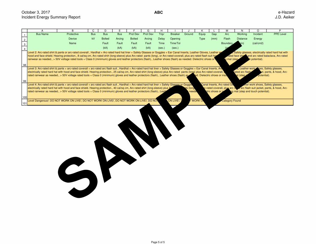
Level 3: Arc-rated shirt & pants + arc-rated coverall + arc-rated arc flash suit , Hardhat + Arc-rated hard hat liner + Safety Glasses or Goggles + Ear Canal Inserts, Arc-rated Gloves, Leather work shoes, Safety glasses,
electrically rated hard hat with hood and face shield. Hearing protection., 25 cal/sq cm, Arc-rated shirt (long-sleeve) plus Arc-rated pants (long) plus Arc-rated coverall, plus arc rated arc flash suit jacket, pants, & hood, Arc-
rated rainwear as needed., > 50V voltage rated tools + Class 0 (minimum) gloves and leather protectors (flash)., Leather shoes (flash) as needed. Dielectric shoes or insulating mat (step and touch potential).
Level 4: Arc-rated shirt & pants + arc-rated coverall + arc-rated arc flash suit , Hardhat + Arc-rated hard hat liner + Safety Glasses or Goggles + Ear Canal Inserts, Arc-rated Gloves, Leather work shoes, Safety glasses,
electrically rated hard hat with hood and face shield. Hearing protection., 40 cal/sq cm, Arc-rated shirt (long-sleeve) plus Arc-rated pants (long) plus Arc-rated coverall, plus arc rated arc flash suit jacket, pants, & hood, Arc-
rated rainwear as needed., > 50V voltage rated tools + Class 0 (minimum) gloves and leather protectors (flash)., Leather shoes (flash) as needed. Dielectric shoes or insulating mat (step and touch potential).
Level Dangerous!: DO NOT WORK ON LIVE!, DO NOT WORK ON LIVE!, DO NOT WORK ON LIVE!, DO NOT WORK ON LIVE!, DO NOT WORK ON LIVE!, No FR Category Found
Level 2: Arc-rated shirt & pants or arc-rated coverall , Hardhat + Arc-rated hard hat liner + Safety Glasses or Goggles + Ear Canal Inserts, Leather Gloves, Leather work shoes, Safety glasses, electrically rated hard hat with
hood and face shield. Hearing protection., 8 cal/sq cm, Arc-rated shirt (long-sleeve) plus Arc-rated pants (long), or Arc-rated coverall, plus arc-rated flash suit hood or arc-rated face shield and arc rated balaclava, Arc-rated
rainwear as needed., > 50V voltage rated tools + Class 0 (minimum) gloves and leather protectors (flash)., Leather shoes (flash) as needed. Dielectric shoes or insulating mat (step and touch potential).
Page 5 of 5
SAMPLE
October 3, 2017 Equipment Evaluation Report
ABC e-Hazard
J.D. Aeiker
1
2
3
4
5
6
7
8
9
10
11
12
13
14
15
16
17
18
19
20
21
22
23
24
25
26
27
28
29
30
31
32
33
34
35
36
37
38
39
40
41
42
43
44
45
46
47
48
49
50
51
52
53
A B C D E F G
Device/Bus Status Description Voltage (V) Continuous Amps INT kA Rating%
Manufacturer Bus/Device LF/Dev/Rating% Calc/Dev/Series Volt/INT/C-L
Comp. Room - Compressor CB Pass SFLA, Spectra RMS 480 90.69 41.95 (*N1) 100.00
Compressor Room Main Bus 70-250A 480 250.00 65.00 64.54
GE SFLA 36.28
Comp. Room - Typ 125A/150A CB Pass SFLA, Spectra RMS 480 0.00 41.95 (*N1) 100.00
Compressor Room Main Bus 70-250A 480 150.00 65.00 64.54
GE SFLA 0.00
Comp. Room - Typ 30A/80A CB Pass SELA, Spectra RMS 480 0.00 41.95 (*N1) 100.00
Compressor Room Main Bus 15-150A 480 80.00 65.00 64.54
GE SELA 0.00
Compressor Room Main FD Pass A4BY, 600V Class L 480 90.69 42.44 (*N1) 80.00
Compressor Room Main FD Bus 200-6000A 600 3000.00 200.00 21.22
GOULD SHAWMUT A4BY 3.02
Compressor Room Main SW Pass TPS Power Break 480 90.69 42.44 (*N1) 100.00
Compressor Room Main FD Bus LSI, 3000A 480 3000.00 100.00 42.44
GE TPS 3.02
Compressor Room Utility Cutout Fail SM-4, 25kV E-Rated 22860 1.90 *25.74 99.39
BUS-0024 3E-200E Standard Speed 23000 100.00 9.40 *273.86
S&C SM-4, 100E 1.90 *234.58
Plant Elec - Bus 1 Pass SGLA, Spectra RMS 480 0.00 41.95 (*N1) 100.00
Compressor Room Main Bus 125-600A 480 400.00 65.00 64.54
GE SGLA 0.00
Plant Elec - Bus 10 Pass SGLA, Spectra RMS 480 0.00 40.17 (*N1) 100.00
Plant Electric Room Main Bus 125-600A 480 400.00 65.00 61.80
GE SGLA 0.00
Plant Elec - Bus 2 Pass SGLA, Spectra RMS 480 0.00 41.95 (*N1) 100.00
Compressor Room Main Bus 125-600A 480 400.00 65.00 64.54
GE SGLA 0.00
Plant Elec - Bus 3 Pass SGLA, Spectra RMS 480 0.00 41.95 (*N1) 100.00
Compressor Room Main Bus 125-600A 480 400.00 65.00 64.54
GE SGLA 0.00
Plant Elec - Bus 4 Pass SGLA, Spectra RMS 480 0.00 41.95 (*N1) 100.00
Compressor Room Main Bus 125-600A 480 400.00 65.00 64.54
GE SGLA 0.00
Plant Elec - Bus 5 Pass SGLA, Spectra RMS 480 0.00 41.95 (*N1) 100.00
Compressor Room Main Bus 125-600A 480 400.00 65.00 64.54
GE SGLA 0.00
Plant Elec - Bus 6 Pass SGLA, Spectra RMS 480 0.00 41.95 (*N1) 100.00
Compressor Room Main Bus 125-600A 480 400.00 65.00 64.54
GE SGLA 0.00
Page 1 of 6
SAMPLE

October 3, 2017 Equipment Evaluation Report
ABC e-Hazard
J.D. Aeiker
1
2
A B C D E F G
Device/Bus Status Description Voltage (V) Continuous Amps INT kA Rating%
Manufacturer Bus/Device LF/Dev/Rating% Calc/Dev/Series Volt/INT/C-L
54
55
56
57
58
59
60
61
62
63
64
65
66
67
68
69
70
71
72
73
74
75
76
77
78
79
80
81
82
83
84
85
86
87
88
89
90
91
92
93
94
95
96
97
98
99
100
101
102
103
104
Plant Elec - Bus 7 Pass SGLA, Spectra RMS 480 0.00 40.17 (*N1) 100.00
Plant Electric Room Main Bus 125-600A 480 400.00 65.00 61.80
GE SGLA 0.00
Plant Elec - Bus 8 Pass SGLA, Spectra RMS 480 0.00 40.17 (*N1) 100.00
Plant Electric Room Main Bus 125-600A 480 400.00 65.00 61.80
GE SGLA 0.00
Plant Elec - Bus 9 Pass SGLA, Spectra RMS 480 0.00 40.17 (*N1) 100.00
Plant Electric Room Main Bus 125-600A 480 400.00 65.00 61.80
GE SGLA 0.00
Plant Elec - Furnace 701 CB Pass SGLA, Spectra RMS 480 152.28 40.17 (*N1) 100.00
Plant Electric Room Main Bus 125-600A 480 500.00 65.00 61.80
GE SGLA 30.46
Plant Elec - Furnace 702 CB Pass SGLA, Spectra RMS 480 152.48 40.17 (*N1) 100.00
Plant Electric Room Main Bus 125-600A 480 500.00 65.00 61.80
GE SGLA 30.50
Plant Electric Room Main FD Pass A4BY, 600V Class L 480 304.76 40.59 (*N1) 80.00
Plant Electric Main FD Bus 200-6000A 600 3000.00 200.00 20.29
GOULD SHAWMUT A4BY 10.16
Plant Electric Room Main SW Pass TPS Power Break 480 304.76 40.59 (*N1) 100.00
Plant Electric Main FD Bus LSI, 3000A 480 3000.00 100.00 40.59
GE TPS 10.16
Plant Electric Utility Cutouts Fail SM-4, 25kV E-Rated 22860 6.40 *24.33 99.39
BUS-0008 3E-200E Standard Speed 23000 100.00 9.40 *258.86
S&C SM-4, 100E 6.40 *214.48
Typ 100A FD - Bus 1 Pass FRS-R, 600V Class RK5 480 0.00 15.76 80.00
Bus 1 - End 1-600A 600 100.00 200.00 7.88
BUSSMANN FRS-R 0.00
Typ 100A FD - Bus 10 Pass FRS-R, 600V Class RK5 480 0.00 27.32 80.00
Bus 10 - End 1-600A 600 100.00 200.00 13.66
BUSSMANN FRS-R 0.00
Typ 100A FD - Bus 2 Pass FRS-R, 600V Class RK5 480 0.00 17.66 80.00
Bus 2 - End 1-600A 600 100.00 200.00 8.83
BUSSMANN FRS-R 0.00
Typ 100A FD - Bus 3 Pass FRS-R, 600V Class RK5 480 0.00 16.94 80.00
Bus 3 - End 1-600A 600 100.00 200.00 8.47
BUSSMANN FRS-R 0.00
Typ 100A FD - Bus 4 Pass FRS-R, 600V Class RK5 480 0.00 14.79 80.00
Bus 4 - End 1-600A 600 100.00 200.00 7.39
Page 2 of 6
SAMPLE

October 3, 2017 Equipment Evaluation Report
ABC e-Hazard
J.D. Aeiker
1
2
A B C D E F G
Device/Bus Status Description Voltage (V) Continuous Amps INT kA Rating%
Manufacturer Bus/Device LF/Dev/Rating% Calc/Dev/Series Volt/INT/C-L
105
106
107
108
109
110
111
112
113
114
115
116
117
118
119
120
121
122
123
124
125
126
127
128
129
130
131
132
133
134
135
136
137
138
139
140
141
142
143
144
145
146
147
148
149
150
151
152
153
154
155
BUSSMANN FRS-R 0.00
Typ 100A FD - Bus 5 Pass FRS-R, 600V Class RK5 480 0.00 12.87 80.00
Bus 5 - End 1-600A 600 100.00 200.00 6.44
BUSSMANN FRS-R 0.00
Typ 100A FD - Bus 6 Pass FRS-R, 600V Class RK5 480 0.00 15.30 80.00
Bus 6 - End 1-600A 600 100.00 200.00 7.65
BUSSMANN FRS-R 0.00
Typ 100A FD - Bus 7 Pass FRS-R, 600V Class RK5 480 0.00 11.47 80.00
Bus 7 - End 1-600A 600 100.00 200.00 5.74
BUSSMANN FRS-R 0.00
Typ 100A FD - Bus 8 Pass FRS-R, 600V Class RK5 480 0.00 14.00 80.00
Bus 8 - End 1-600A 600 100.00 200.00 7.00
BUSSMANN FRS-R 0.00
Typ 100A FD - Bus 9 Pass FRS-R, 600V Class RK5 480 0.00 11.11 80.00
Bus 9 - End 1-600A 600 100.00 200.00 5.56
BUSSMANN FRS-R 0.00
Typ 200A FD - Bus 1 Pass FRS-R, 600V Class RK5 480 0.00 15.76 80.00
Bus 1 - End 1-600A 600 200.00 200.00 7.88
BUSSMANN FRS-R 0.00
Typ 200A FD - Bus 10 Pass FRS-R, 600V Class RK5 480 0.00 27.32 80.00
Bus 10 - End 1-600A 600 200.00 200.00 13.66
BUSSMANN FRS-R 0.00
Typ 200A FD - Bus 2 Pass FRS-R, 600V Class RK5 480 0.00 17.66 80.00
Bus 2 - End 1-600A 600 200.00 200.00 8.83
BUSSMANN FRS-R 0.00
Typ 200A FD - Bus 3 Pass FRS-R, 600V Class RK5 480 0.00 16.94 80.00
Bus 3 - End 1-600A 600 200.00 200.00 8.47
BUSSMANN FRS-R 0.00
Typ 200A FD - Bus 4 Pass FRS-R, 600V Class RK5 480 0.00 14.79 80.00
Bus 4 - End 1-600A 600 200.00 200.00 7.39
BUSSMANN FRS-R 0.00
Typ 200A FD - Bus 5 Pass FRS-R, 600V Class RK5 480 0.00 12.87 80.00
Bus 5 - End 1-600A 600 200.00 200.00 6.44
BUSSMANN FRS-R 0.00
Typ 200A FD - Bus 6 Pass FRS-R, 600V Class RK5 480 0.00 15.30 80.00
Bus 6 - End 1-600A 600 200.00 200.00 7.65
BUSSMANN FRS-R 0.00
Typ 200A FD - Bus 7 Pass FRS-R, 600V Class RK5 480 0.00 11.47 80.00
Page 3 of 6
SAMPLE

October 3, 2017 Equipment Evaluation Report
ABC e-Hazard
J.D. Aeiker
1
2
A B C D E F G
Device/Bus Status Description Voltage (V) Continuous Amps INT kA Rating%
Manufacturer Bus/Device LF/Dev/Rating% Calc/Dev/Series Volt/INT/C-L
156
157
158
159
160
161
162
163
164
165
166
167
168
169
170
171
172
173
174
175
176
177
178
179
180
181
182
183
184
185
186
187
188
189
190
191
192
193
194
195
196
197
198
199
200
201
202
203
204
205
206
Bus 7 - End 1-600A 600 200.00 200.00 5.74
BUSSMANN FRS-R 0.00
Typ 200A FD - Bus 8 Pass FRS-R, 600V Class RK5 480 0.00 14.00 80.00
Bus 8 - End 1-600A 600 200.00 200.00 7.00
BUSSMANN FRS-R 0.00
Typ 200A FD - Bus 9 Pass FRS-R, 600V Class RK5 480 0.00 11.11 80.00
Bus 9 - End 1-600A 600 200.00 200.00 5.56
BUSSMANN FRS-R 0.00
Typ 208V XFMR FD - Bus 1 Pass FRS-R, 600V Class RK5 480 0.00 15.76 80.00
Bus 1 - End 1-600A 600 100.00 200.00 7.88
BUSSMANN FRS-R 0.00
Typ 208V XFMR FD - Bus 10 Pass FRS-R, 600V Class RK5 480 0.00 27.32 80.00
Bus 10 - End 1-600A 600 100.00 200.00 13.66
BUSSMANN FRS-R 0.00
Typ 208V XFMR FD - Bus 2 Pass FRS-R, 600V Class RK5 480 0.00 17.66 80.00
Bus 2 - End 1-600A 600 100.00 200.00 8.83
BUSSMANN FRS-R 0.00
Typ 208V XFMR FD - Bus 3 Pass FRS-R, 600V Class RK5 480 0.00 16.94 80.00
Bus 3 - End 1-600A 600 100.00 200.00 8.47
BUSSMANN FRS-R 0.00
Typ 208V XFMR FD - Bus 4 Pass FRS-R, 600V Class RK5 480 0.00 14.79 80.00
Bus 4 - End 1-600A 600 100.00 200.00 7.39
BUSSMANN FRS-R 0.00
Typ 208V XFMR FD - Bus 5 Pass FRS-R, 600V Class RK5 480 0.00 12.87 80.00
Bus 5 - End 1-600A 600 100.00 200.00 6.44
BUSSMANN FRS-R 0.00
Typ 208V XFMR FD - Bus 6 Pass FRS-R, 600V Class RK5 480 0.00 15.30 80.00
Bus 6 - End 1-600A 600 100.00 200.00 7.65
BUSSMANN FRS-R 0.00
Typ 208V XFMR FD - Bus 7 Pass FRS-R, 600V Class RK5 480 0.00 11.47 80.00
Bus 7 - End 1-600A 600 100.00 200.00 5.74
BUSSMANN FRS-R 0.00
Typ 208V XFMR FD - Bus 8 Pass FRS-R, 600V Class RK5 480 0.00 14.00 80.00
Bus 8 - End 1-600A 600 100.00 200.00 7.00
BUSSMANN FRS-R 0.00
Typ 208V XFMR FD - Bus 9 Pass FRS-R, 600V Class RK5 480 0.00 11.11 80.00
Bus 9 - End 1-600A 600 100.00 200.00 5.56
BUSSMANN FRS-R 0.00
Page 4 of 6
SAMPLE

October 3, 2017 Equipment Evaluation Report
ABC e-Hazard
J.D. Aeiker
1
2
A B C D E F G
Device/Bus Status Description Voltage (V) Continuous Amps INT kA Rating%
Manufacturer Bus/Device LF/Dev/Rating% Calc/Dev/Series Volt/INT/C-L
207
208
209
210
211
212
213
214
215
216
217
218
219
220
221
222
223
224
225
226
227
228
229
230
231
232
233
234
235
236
237
238
239
240
241
242
243
244
245
246
247
248
249
250
251
252
253
254
255
256
257
Typ 240V XFMR FD - Bus 1 Pass FRS-R, 600V Class RK5 480 0.00 15.76 80.00
Bus 1 - End 1-600A 600 45.00 200.00 7.88
BUSSMANN FRS-R 0.00
Typ 240V XFMR FD - Bus 10 Pass FRS-R, 600V Class RK5 480 0.00 27.32 80.00
Bus 10 - End 1-600A 600 100.00 200.00 13.66
BUSSMANN FRS-R 0.00
Typ 240V XFMR FD - Bus 2 Pass FRS-R, 600V Class RK5 480 0.00 17.66 80.00
Bus 2 - End 1-600A 600 100.00 200.00 8.83
BUSSMANN FRS-R 0.00
Typ 240V XFMR FD - Bus 3 Pass FRS-R, 600V Class RK5 480 0.00 16.94 80.00
Bus 3 - End 1-600A 600 100.00 200.00 8.47
BUSSMANN FRS-R 0.00
Typ 240V XFMR FD - Bus 4 Pass FRS-R, 600V Class RK5 480 0.00 14.79 80.00
Bus 4 - End 1-600A 600 100.00 200.00 7.39
BUSSMANN FRS-R 0.00
Typ 240V XFMR FD - Bus 5 Pass FRS-R, 600V Class RK5 480 0.00 12.87 80.00
Bus 5 - End 1-600A 600 100.00 200.00 6.44
BUSSMANN FRS-R 0.00
Typ 240V XFMR FD - Bus 6 Pass FRS-R, 600V Class RK5 480 0.00 15.30 80.00
Bus 6 - End 1-600A 600 100.00 200.00 7.65
BUSSMANN FRS-R 0.00
Typ 240V XFMR FD - Bus 7 Pass FRS-R, 600V Class RK5 480 0.00 11.47 80.00
Bus 7 - End 1-600A 600 100.00 200.00 5.74
BUSSMANN FRS-R 0.00
Typ 240V XFMR FD - Bus 8 Pass FRS-R, 600V Class RK5 480 0.00 14.00 80.00
Bus 8 - End 1-600A 600 100.00 200.00 7.00
BUSSMANN FRS-R 0.00
Typ 240V XFMR FD - Bus 9 Pass FRS-R, 600V Class RK5 480 0.00 11.11 80.00
Bus 9 - End 1-600A 600 100.00 200.00 5.56
BUSSMANN FRS-R 0.00
Typ 30A FD - Bus 1 Pass FRS-R, 600V Class RK5 480 0.00 15.76 80.00
Bus 1 - End 1-600A 600 30.00 200.00 7.88
BUSSMANN FRS-R 0.00
Typ 30A FD - Bus 10 Pass FRS-R, 600V Class RK5 480 0.00 27.32 80.00
Bus 10 - End 1-600A 600 100.00 200.00 13.66
BUSSMANN FRS-R 0.00
Typ 30A FD - Bus 2 Pass FRS-R, 600V Class RK5 480 0.00 17.66 80.00
Bus 2 - End 1-600A 600 100.00 200.00 8.83
BUSSMANN FRS-R 0.00
Page 5 of 6
SAMPLE
October 3, 2017 Equipment Evaluation Report
ABC e-Hazard
J.D. Aeiker
1
2
A B C D E F G
Device/Bus Status Description Voltage (V) Continuous Amps INT kA Rating%
Manufacturer Bus/Device LF/Dev/Rating% Calc/Dev/Series Volt/INT/C-L
258
259
260
261
262
263
264
265
266
267
268
269
270
271
272
273
274
275
276
277
278
279
280
281
282
283
284
285
286
287
288
289
290
291
292
293
294
Typ 30A FD - Bus 3 Pass FRS-R, 600V Class RK5 480 0.00 16.94 80.00
Bus 3 - End 1-600A 600 100.00 200.00 8.47
BUSSMANN FRS-R 0.00
Typ 30A FD - Bus 4 Pass FRS-R, 600V Class RK5 480 0.00 14.79 80.00
Bus 4 - End 1-600A 600 100.00 200.00 7.39
BUSSMANN FRS-R 0.00
Typ 30A FD - Bus 5 Pass FRS-R, 600V Class RK5 480 0.00 12.87 80.00
Bus 5 - End 1-600A 600 100.00 200.00 6.44
BUSSMANN FRS-R 0.00
Typ 30A FD - Bus 6 Pass FRS-R, 600V Class RK5 480 0.00 15.30 80.00
Bus 6 - End 1-600A 600 100.00 200.00 7.65
BUSSMANN FRS-R 0.00
Typ 30A FD - Bus 7 Pass FRS-R, 600V Class RK5 480 0.00 11.47 80.00
Bus 7 - End 1-600A 600 100.00 200.00 5.74
BUSSMANN FRS-R 0.00
Typ 30A FD - Bus 8 Pass FRS-R, 600V Class RK5 480 0.00 14.00 80.00
Bus 8 - End 1-600A 600 100.00 200.00 7.00
BUSSMANN FRS-R 0.00
Typ 30A FD - Bus 9 Pass FRS-R, 600V Class RK5 480 0.00 11.11 80.00
Bus 9 - End 1-600A 600 100.00 200.00 5.56
BUSSMANN FRS-R 0.00
Typical LL Panel Branch CB Fail TED (E-100 Line) 480 0.00 *24.36 100.00
Comp. Room - Typ 125A/150A Bus 15-100A, 2-3 Pole 480 50.00 14.00 *174.00
GE TED 0.00
(*N1) System X/R higher than Test X/R, Calc INT kA modified based on low voltage factor.
(*Calc INT kA) Device did not pass. Device is either Marginal (90%) or Failed (100%) of the device library interrupting rating.
(*Calc C-L kA) Device did not pass. Device is either Marginal (90%) or Failed (100%) of the device library close-latch / momentary rating.
Page 6 of 6
SAMPLE

Hea
dBod
yHan
dsFe
et
Best
Practi
ces Rated UndergarmentsDI/EH Work Shoes
Rated Hard Hat LinerRated Jacket, Parka, or Rainwear
• Workingunderpowerlines• Highstep-potentialrisk• Wetconditions
Leather Work Shoes
RatedlongsleeveShirt&RatedPants
Rated Flash Hood
RatedFace Shield with Rated Balaclava
RatedFace Shield
Rated Gloves
Hard Hat Safety Glasses/Goggles
Hearing Protection
orRatedCoverall
Rated Arc Flash Suitor
or
orRubberInsulating Gloves
with Leather Protectors
or
HeavyDutyLeatherGloves
or
4 cal/cm2
PPE Min. Arc Rating8 cal/cm2
PPE Min. Arc Rating40 cal/cm2
PPE Min. Arc Rating PPE Min. Arc Rating25 cal/cm2
Are You Protected?
PersonalProtectiveEquipment for the task
TakingtheFlashOutofElectricalSafetyCheck to
be sure
you have cor
rect
(502) 716-7073e-Hazard.com
Arc-RatedRequired by NFPA 70ERequired, Choices AvailableAs Needed Recommended Best Practice
v1501 | © 2015 e-Hazard Management, LLC.
25 cal/cm2
Arc Rating40 cal/cm2
Arc Rating
Dielectric Shoes
Best Practicesfor
Exposureup to:
1.2cal/cm2
Eye and Hearing Protection
HeavyDutyLeatherGloves
EHLeatherWorkShoes
LongsleeveShirtLongPantsUndergarments
ALLClothingMadeofNonmeltingorUntreated Natural Fiber
SAMPLE

3 Labels
Compressor Room Main Bus
Typical for: - SSR Compressor #1 - SSR Compressor #2 - New IR Compressor
Furnace 701
3 Labels
ABC CORPORATION
ABC CAT Subsidary CORPORATION Someplace, S T
ABC CORPORATION - Someplace, ST Arc FlashStudy - Model Drawing e-Hazard - Louisville, KYJ. D. Aeiker October 3, 2017 Rev. 0
Plant Electric Room Main Bus - MPD-2
3 Labels
2 Labels 2 Labels
2 Labels 2 Labels
Plant Electric Room Main Bus - MDP-2
Furnace 702
6 Labels
NOTE #2: DANGEROUS!! VERY HIGH INCIDENT ENERGYOperation of protective devices on the Plant Electric Room Main Bus is Dangerous; >40 calories/cm2.
The DANGEROUS Level may be mitigated by increasing theworking distance from 18" to 38". This increase in working distancewould reduce the Incident Energy from 128 cal/cm2 to 38 cal/cm2 and enable the use of AF PPE Level 4 for operation of protective devices on the Plant Electric Room Main Bus. The AFB remains the same in either case.
NOTE #1: DANGEROUS!! VERY HIGH INCIDENT ENERGYOperation of the Plant Electric Room Main Fused Disconnect is Dangerous; >40 calories/cm2.
The DANGEROUS Level may be mitigated by increasing theworking distance from 18" to 38". This increase in working distancewould reduce the Incident Energy from 128 cal/cm2 to 37 cal/cm2 and enable the use of AF PPE Level 4 for operation of the Plant Electric Room Main Fused Disconnect. The AFB remains the same in either case.
NOTE #3: DANGEROUS!! VERY HIGH INCIDENT ENERGYOperation of the Compressor Room Main Fused Disconnect is Dangerous; >40 calories/cm2.
The DANGEROUS Level may be mitigated by increasing theworking distance from 18" to 38". This increase in working distancewould reduce the Incident Energy from 125 cal/cm2 to 37 cal/cm2 and enable the use of AF PPE Level 4 for operation of the Compressor Room Main Fused Disconnect. The AFB remains the same in either case.
NOTE #2: DANGEROUS!! VERY HIGH INCIDENT ENERGYOperation of protective devices on the Compressor Room Main Bus is Dangerous; >40 calories/cm2.
The DANGEROUS Level may be mitigated by increasing theworking distance from 18" to 38". This increase in working distancewould reduce the Incident Energy from 125 cal/cm2 to 37 cal/cm2 and enable the use of AF PPE Level 4 for operation of protective devices on the Compressor Room Main Bus. The AFB remains the same in either case.
6 Labels
Typical for:
- LL1 Panel MLO
- LL2 Panel MLO
- LL3 Panel MLO
- LL5 Panel MLO
- New Addition Panel MLO
- Assorted Spares
and other similar LL
panels fed from
Compressor Room Main
12 Labels
Typical for: - PP1 Panel MLO- PP10 Panel MLO and similar panels or field devices
20 Labels
Typical for:
- LL1 Panel Field Devices
- LL2 Panel Field Devices
- LL3 Panel Field Devices
- LL5 Panel Field Devices
- New Addition Panel Field Devices
and similar panels or field
devices
30 Labels
Typical for:
- CU 2-10
- Air Dryers
- Assorted Spares
and other similar loads
fed from Compressor
Room Main
18 Labels
Compressor Room Main Bus
Plant Electric Main FD Bus
Eversource - Plant ElectricSystemNominalVoltage 22860.0 VSC Contribution 3P 22561.0 Amps
S
P
XFMR - Plant Electric RoomNominal kVA 2000.0 kVAPri RatedVoltage 22860 VSec RatedVoltage 480 VZ% 6.2000 %Ampacity 58.1 AAmpacity Sec 2766.5 A
Eversource - Compressor RoomSystemNominalVoltage 22860.0 VSC Contribution 3P 23736.0 Amps
S
P
XFMR - Compressor RoomNominal kVA 2000.0 kVAPri RatedVoltage 22860 VSec RatedVoltage 480 VZ% 5.7000 %Ampacity 58.1 AAmpacity Sec 2766.5 A
Compressor Room Main FD Bus
Voltage 480.0 VIsc 3P 39951.63 AAF_TripTime 2.000 sAF_IncidentEnergy 125.32 Cal/cm^2AF_PPE Category Dangerous!AF_Boundary 306.64 inchesAF_ArcingFault 18.197 kA
Plant Electric Utility CutoutsS&C Model SM-4, 100EVoltage 22860.0 VRated Current 100.0 AInterrupt Rating 9.4 kATrip 100.0 ASettings
100 Amps
CBL-0001(6) 500 AWG 25.0 ftInstallation ConduitAmpacity 2580.0 A
Plant Electric Main FD Bus
Voltage 480.0 VIsc 3P 38106.89 AAF_TripTime 1.838 sAF_IncidentEnergy 127.67 Cal/cm^2AF_PPE Category Dangerous!AF_Boundary 310.13 inchesAF_ArcingFault 20.561 kA
Plant Electric Room Main FDGOULD SHAWMUT Model A4BYVoltage 480.0 VRated Current 3000.0 AInterrupt Rating 200.0 kATrip 3000.0 A
Plant Electric Room Main Bus
Voltage 480.0 VIsc 3P 37951.39 AAF_TripTime 1.856 sAF_IncidentEnergy 128.41 Cal/cm^2AF_PPE Category Dangerous!AF_Boundary 311.22 inchesAF_ArcingFault 20.490 kA
CBL-0002(1) 3000 AWG 10.0 ftInstallation SandwichAmpacity 3000.0 A
CBL-0003(1) 2/0 AWG 300.0 ftInstallation Direct BuriedAmpacity 288.3 A
Plant Electric Room Main SWGE Model TPSVoltage 480.0 VRated Current 3000.0 AInterrupt Rating 100.0 kATrip 3000.0 APlug 0.0 A
Plant Elec - Furnace 701 CBGE Model SGLAVoltage 480.0 VRated Current 600.0 AInterrupt Rating 65.0 kATrip 500.0 APlug 0.0 ASettings
MAX
CBL-0004(2) 350 AWG 240.0 ftInstallation ConduitAmpacity 700.0 A
Furnace 701 Bus
Voltage 480.0 VIsc 3P 20035.59 AAF_TripTime 0.025 sAF_IncidentEnergy 1 Cal/cm^2AF_PPE Category 0AF_Boundary 16.14 inchesAF_ArcingFault 11.873 kA
Plant Elec - Furnace 702 CBGE Model SGLAVoltage 480.0 VRated Current 600.0 AInterrupt Rating 65.0 kATrip 500.0 APlug 0.0 ASettings
MAX
CBL-0005(2) 350 AWG 320.0 ftInstallation ConduitAmpacity 700.0 A
Furnace 702 Bus
Voltage 480.0 VIsc 3P 17281.47 AAF_TripTime 0.025 sAF_IncidentEnergy 0.87 Cal/cm^2AF_PPE Category 0AF_Boundary 14.85 inchesAF_ArcingFault 10.464 kA
Furnance 701 DriveRated HP 125.0 hpRatedVoltage 480 VRatedAmps 150.8 A
S
P
Furnance 701 XFMRNominal kVA 150.0 kVAPri RatedVoltage 480 VSec RatedVoltage 240 VZ% 2.0000 %Ampacity 180.4 AAmpacity Sec 360.8 A
CBL-0006(2) 4/0 AWG 10.0 ftInstallation ConduitAmpacity 520.0 A
Furnance 701 Heater
Voltage 240.0 VIsc 3P 12093.86 AAF_TripTime 2.000 sAF_IncidentEnergy 32.57 Cal/cm^2AF_PPE Category 4AF_Boundary 134.89 inchesAF_ArcingFault 5.235 kA
Furnance 702 DriveRated HP 125.0 hpRatedVoltage 480 VRatedAmps 150.8 A
S
P
Furnance 702 XFMRNominal kVA 150.0 kVAPri RatedVoltage 480 VSec RatedVoltage 240 VZ% 2.0000 %Ampacity 180.4 AAmpacity Sec 360.8 A
CBL-0007(2) 4/0 AWG 10.0 ftInstallation ConduitAmpacity 520.0 A
Furnance 702 Heater
Voltage 240.0 VIsc 3P 11548.70 AAF_TripTime 2.000 sAF_IncidentEnergy 31.34 Cal/cm^2AF_PPE Category 4AF_Boundary 131.78 inchesAF_ArcingFault 5.064 kA
Plant Elec - Bus 10GE Model SGLAVoltage 480.0 VRated Current 400.0 AInterrupt Rating 65.0 kATrip 400.0 APlug 0.0 ASettings
MAX
CBL-0008(2) 4/0 AWG 20.0 ftInstallation ConduitAmpacity 520.0 A
Bus 10 - Begin
Voltage 480.0 VIsc 3P 35031.27 AAF_TripTime 0.025 sAF_IncidentEnergy 1.67 Cal/cm^2AF_PPE Category 1AF_Boundary 22.1 inchesAF_ArcingFault 19.135 kA
CBL-0009(1) 400 AWG 60.0 ftInstallation SandwichAmpacity 400.0 A
Bus 10 - End
Voltage 480.0 VIsc 3P 27320.87 AAF_TripTime 0.025 sAF_IncidentEnergy 1.33 Cal/cm^2AF_PPE Category 1AF_Boundary 19.22 inchesAF_ArcingFault 15.474 kA
Plant Elec - Bus 9GE Model SGLAVoltage 480.0 VRated Current 400.0 AInterrupt Rating 65.0 kATrip 400.0 APlug 0.0 ASettings
MAX
CBL-0010(2) 4/0 AWG 250.0 ftInstallation ConduitAmpacity 520.0 A
Bus 9 - Begin
Voltage 480.0 VIsc 3P 17073.52 AAF_TripTime 0.025 sAF_IncidentEnergy 0.86 Cal/cm^2AF_PPE Category 0AF_Boundary 14.75 inchesAF_ArcingFault 10.356 kA
CBL-0011(1) 400 AWG 210.0 ftInstallation SandwichAmpacity 400.0 A
Bus 9 - End
Voltage 480.0 VIsc 3P 11112.18 AAF_TripTime 0.025 sAF_IncidentEnergy 0.58 Cal/cm^2AF_PPE Category 0AF_Boundary 11.58 inchesAF_ArcingFault 7.176 kA
Plant Elec - Bus 8GE Model SGLAVoltage 480.0 VRated Current 400.0 AInterrupt Rating 65.0 kATrip 400.0 APlug 0.0 ASettings
MAX
CBL-0012(2) 4/0 AWG 230.0 ftInstallation ConduitAmpacity 520.0 A
Bus 8 - Begin
Voltage 480.0 VIsc 3P 17922.24 AAF_TripTime 0.025 sAF_IncidentEnergy 0.9 Cal/cm^2AF_PPE Category 0AF_Boundary 15.16 inchesAF_ArcingFault 10.794 kA
CBL-0013(1) 400 AWG 105.0 ftInstallation SandwichAmpacity 400.0 A
Bus 8 - End
Voltage 480.0 VIsc 3P 13997.60 AAF_TripTime 0.025 sAF_IncidentEnergy 0.72 Cal/cm^2AF_PPE Category 0AF_Boundary 13.19 inchesAF_ArcingFault 8.740 kA
Plant Elec - Bus 7GE Model SGLAVoltage 480.0 VRated Current 400.0 AInterrupt Rating 65.0 kATrip 400.0 APlug 0.0 ASettings
MAX
CBL-0014(2) 4/0 AWG 230.0 ftInstallation ConduitAmpacity 520.0 A
Bus 7 - Begin
Voltage 480.0 VIsc 3P 17922.24 AAF_TripTime 0.025 sAF_IncidentEnergy 0.9 Cal/cm^2AF_PPE Category 0AF_Boundary 15.16 inchesAF_ArcingFault 10.794 kA
CBL-0015(1) 400 AWG 210.0 ftInstallation SandwichAmpacity 400.0 A
Bus 7 - End
Voltage 480.0 VIsc 3P 11472.62 AAF_TripTime 0.025 sAF_IncidentEnergy 0.6 Cal/cm^2AF_PPE Category 0AF_Boundary 11.79 inchesAF_ArcingFault 7.374 kA
Compressor Room Utility CutoutS&C Model SM-4, 100EVoltage 22860.0 VRated Current 100.0 AInterrupt Rating 9.4 kATrip 100.0 ASettings
100 Amps
CBL-0016(1) 2/0 AWG 300.0 ftInstallation Direct BuriedAmpacity 288.3 A
CBL-0017(6) 500 AWG 25.0 ftInstallation ConduitAmpacity 2580.0 A
CBL-0018(1) 3000 AWG 10.0 ftInstallation SandwichAmpacity 3000.0 A
Compressor Room Main SWGE Model TPSVoltage 480.0 VRated Current 3000.0 AInterrupt Rating 100.0 kATrip 3000.0 APlug 0.0 A
Compressor Room Main Bus
Voltage 480.0 VIsc 3P 39768.70 AAF_TripTime 2.000 sAF_IncidentEnergy 124.79 Cal/cm^2AF_PPE Category Dangerous!AF_Boundary 305.84 inchesAF_ArcingFault 18.126 kA
Compressor Room Main FDGOULD SHAWMUT Model A4BYVoltage 480.0 VRated Current 3000.0 AInterrupt Rating 200.0 kATrip 3000.0 A
Plant Elec - Bus 4GE Model SGLAVoltage 480.0 VRated Current 400.0 AInterrupt Rating 65.0 kATrip 400.0 APlug 0.0 ASettings
MAX
CBL-0019(2) 4/0 AWG 130.0 ftInstallation ConduitAmpacity 520.0 A
Bus 4 - Begin
Voltage 480.0 VIsc 3P 24324.63 AAF_TripTime 0.025 sAF_IncidentEnergy 1.2 Cal/cm^2AF_PPE Category 0AF_Boundary 18 inchesAF_ArcingFault 14.012 kA
CBL-0020(1) 400 AWG 180.0 ftInstallation SandwichAmpacity 400.0 A
Bus 4 - End
Voltage 480.0 VIsc 3P 14789.36 AAF_TripTime 0.025 sAF_IncidentEnergy 0.75 Cal/cm^2AF_PPE Category 0AF_Boundary 13.6 inchesAF_ArcingFault 9.160 kA
Plant Elec - Bus 3GE Model SGLAVoltage 480.0 VRated Current 400.0 AInterrupt Rating 65.0 kATrip 400.0 APlug 0.0 ASettings
MAX
CBL-0021(2) 4/0 AWG 100.0 ftInstallation ConduitAmpacity 520.0 A
Bus 3 - Begin
Voltage 480.0 VIsc 3P 26901.03 AAF_TripTime 0.025 sAF_IncidentEnergy 1.31 Cal/cm^2AF_PPE Category 1AF_Boundary 19.05 inchesAF_ArcingFault 15.271 kA
CBL-0022(1) 400 AWG 150.0 ftInstallation SandwichAmpacity 400.0 A
Bus 3 - End
Voltage 480.0 VIsc 3P 16942.03 AAF_TripTime 0.025 sAF_IncidentEnergy 0.86 Cal/cm^2AF_PPE Category 0AF_Boundary 14.69 inchesAF_ArcingFault 10.288 kA
Plant Elec - Bus 2GE Model SGLAVoltage 480.0 VRated Current 400.0 AInterrupt Rating 65.0 kATrip 400.0 APlug 0.0 ASettings
MAX
CBL-0023(2) 4/0 AWG 50.0 ftInstallation ConduitAmpacity 520.0 A
Bus 2 - Begin
Voltage 480.0 VIsc 3P 32382.34 AAF_TripTime 0.025 sAF_IncidentEnergy 1.56 Cal/cm^2AF_PPE Category 1AF_Boundary 21.14 inchesAF_ArcingFault 17.892 kA
CBL-0024(1) 400 AWG 180.0 ftInstallation SandwichAmpacity 400.0 A
Bus 2 - End
Voltage 480.0 VIsc 3P 17661.64 AAF_TripTime 0.025 sAF_IncidentEnergy 0.89 Cal/cm^2AF_PPE Category 0AF_Boundary 15.03 inchesAF_ArcingFault 10.660 kA
Plant Elec - Bus 1GE Model SGLAVoltage 480.0 VRated Current 400.0 AInterrupt Rating 65.0 kATrip 400.0 APlug 0.0 ASettings
MAX
CBL-0025(2) 4/0 AWG 100.0 ftInstallation ConduitAmpacity 520.0 A
Bus 1 - Begin
Voltage 480.0 VIsc 3P 26901.03 AAF_TripTime 0.025 sAF_IncidentEnergy 1.31 Cal/cm^2AF_PPE Category 1AF_Boundary 19.05 inchesAF_ArcingFault 15.271 kA
CBL-0026(1) 400 AWG 180.0 ftInstallation SandwichAmpacity 400.0 A
Bus 1 - End
Voltage 480.0 VIsc 3P 15757.15 AAF_TripTime 0.025 sAF_IncidentEnergy 0.8 Cal/cm^2AF_PPE Category 0AF_Boundary 14.1 inchesAF_ArcingFault 9.670 kA
Plant Elec - Bus 6GE Model SGLAVoltage 480.0 VRated Current 400.0 AInterrupt Rating 65.0 kATrip 400.0 APlug 0.0 ASettings
MAX
CBL-0027(2) 4/0 AWG 210.0 ftInstallation ConduitAmpacity 520.0 A
Bus 6 - Begin
Voltage 480.0 VIsc 3P 19244.61 AAF_TripTime 0.025 sAF_IncidentEnergy 0.96 Cal/cm^2AF_PPE Category 0AF_Boundary 15.78 inchesAF_ArcingFault 11.471 kA
CBL-0028(1) 400 AWG 90.0 ftInstallation SandwichAmpacity 400.0 A
Bus 6 - End
Voltage 480.0 VIsc 3P 15301.50 AAF_TripTime 0.025 sAF_IncidentEnergy 0.78 Cal/cm^2AF_PPE Category 0AF_Boundary 13.87 inchesAF_ArcingFault 9.431 kA
Plant Elec - Bus 5
GE Model SGLAVoltage 480.0 VRated Current 400.0 AInterrupt Rating 65.0 kATrip 400.0 APlug 0.0 ASettings
MAX
CBL-0029(2) 4/0 AWG 170.0 ftInstallation ConduitAmpacity 520.0 A
Bus 5 - Begin
Voltage 480.0 VIsc 3P 21512.10 AAF_TripTime 0.025 sAF_IncidentEnergy 1.07 Cal/cm^2AF_PPE Category 0AF_Boundary 16.8 inchesAF_ArcingFault 12.616 kA
CBL-0030(1) 400 AWG 210.0 ftInstallation SandwichAmpacity 400.0 A
Bus 5 - End
Voltage 480.0 VIsc 3P 12873.32 AAF_TripTime 0.025 sAF_IncidentEnergy 0.66 Cal/cm^2AF_PPE Category 0AF_Boundary 12.58 inchesAF_ArcingFault 8.137 kA
Comp. Room - Compressor CBGE Model SFLAVoltage 480.0 VRated Current 250.0 AInterrupt Rating 65.0 kATrip 250.0 APlug 0.0 ASettings
MAX
CBL-0031(1) 250 AWG 40.0 ftInstallation ConduitAmpacity 290.0 A
SSR Compressors
Voltage 480.0 VIsc 3P 29538.68 AAF_TripTime 0.025 sAF_IncidentEnergy 1.43 Cal/cm^2AF_PPE Category 1AF_Boundary 20.08 inchesAF_ArcingFault 16.541 kA
Typical Compressor Motor
Rated HP 75.0 hpRatedVoltage 480 VRatedAmps 90.5 A
Comp. Room - Typ 125A/150A CBGE Model SFLAVoltage 480.0 VRated Current 250.0 AInterrupt Rating 65.0 kATrip 150.0 APlug 0.0 ASettings
MAX
CBL-0032(1) 2/0 AWG 50.0 ftInstallation ConduitAmpacity 195.0 A
Comp. Room - Typ 125A/150A Bus
Voltage 480.0 VIsc 3P 24359.97 AAF_TripTime 0.025 sAF_IncidentEnergy 1.2 Cal/cm^2AF_PPE Category 0AF_Boundary 18.01 inchesAF_ArcingFault 14.030 kA
Typical LL Panel Branch CBGE Model TEDVoltage 480.0 VRated Current 50.0 AInterrupt Rating 14.0 kATrip 50.0 APlug 0.0 ASettings
Fixed
CBL-0033(1) 6 AWG 10.0 ftInstallation ConduitAmpacity 75.0 A
Typical LL Panel Field Device
Voltage 480.0 VIsc 3P 18191.89 AAF_TripTime 0.018 sAF_IncidentEnergy 0.66 Cal/cm^2AF_PPE Category 0AF_Boundary 12.51 inchesAF_ArcingFault 10.933 kA
S
P
Typical XFMR off LL PanelNominal kVA 30.0 kVAPri RatedVoltage 480 VSec RatedVoltage 208 VZ% 4.0000 %Ampacity 36.1 AAmpacity Sec 83.3 A
CBL-0034(1) 2 AWG 50.0 ftInstallation ConduitAmpacity 130.0 A
Typ PP Panels & Field Devices
Voltage 208.0 VIsc 3P 1788.02 AAF_TripTime 1.834 sAF_IncidentEnergy 1.2 Cal/cm^2AF_PPE Category 0AF_Boundary 18.04 inchesAF_ArcingFault 1.299 kA
Comp. Room - Typ 30A/80A CBGE Model SELAVoltage 480.0 VRated Current 80.0 AInterrupt Rating 65.0 kATrip 80.0 APlug 0.0 ASettings
MAX
CBL-0035(1) 2 AWG 50.0 ftInstallation ConduitAmpacity 130.0 A
Comp. Room - Typ 30A/80A Bus
Voltage 480.0 VIsc 3P 18629.10 AAF_TripTime 0.025 sAF_IncidentEnergy 0.93 Cal/cm^2AF_PPE Category 0AF_Boundary 15.49 inchesAF_ArcingFault 11.157 kA
SAMPLE

Bus 1
ABC CORPORATION - SOMEPLACE, ST
Arc Flash Study - Model Drawing - Bus Ducts
e-Hazard - Louisville, KY
J. D. Aeiker October 3, 2017 Rev. 0
ABC CORPORATION
ABC SUBSIDARYCORPORATION SOMEPLACE, ST
Typical for: 150A to 400A Bus Loads
Typical for: 70A to 125A Bus Loads
Typical for: 15A to 60A Bus Loads
Typical for all 240V Panels
fed by transformers less
than 125KVA
Typical for all 208V Panels
fed by transformers less
than 125KVA
Bus 1
Typical for: 150A to 400A Bus Loads
Typical for: 70A to 125A Bus Loads
Typical for: 15A to 60A Bus Loads
Typical for all 240V Panels
fed by transformers less
than 125KVA
Typical for all 208V Panels
fed by transformers less
than 125KVA
Bus 2 Bus 2
Typical for: 150A to 400A Bus Loads
Typical for: 70A to 125A Bus Loads
Typical for: 15A to 60A Bus Loads
Typical for all 240V Panels
fed by transformers less
than 125KVA
Typical for all 208V Panels
fed by transformers less
than 125KVA
Typical for: 150A to 400A Bus Loads
Typical for: 70A to 125A Bus Loads
Typical for: 15A to 60A Bus Loads
Typical for all 240V Panels
fed by transformers less
than 125KVA
Typical for all 208V Panels
fed by transformers less
than 125KVA
Typical for: 150A to 400A Bus Loads
Typical for: 70A to 125A Bus Loads
Typical for: 15A to 60A Bus Loads
Typical for all 240V Panels
fed by transformers less
than 125KVA
Typical for all 208V Panels
fed by transformers less
than 125KVA
Typical for: 150A to 400A Bus Loads
Typical for: 70A to 125A Bus Loads
Typical for: 15A to 60A Bus Loads
Typical for all 240V Panels
fed by transformers less
than 125KVA
Typical for all 208V Panels
fed by transformers less
than 125KVA
Typical for: 150A to 400A Bus Loads
Typical for: 70A to 125A Bus Loads
Typical for: 15A to 60A Bus Loads
Typical for all 240V Panels
fed by transformers less
than 125KVA
Typical for all 208V Panels
fed by transformers less
than 125KVA
Typical for: 150A to 400A Bus Loads
Typical for: 70A to 125A Bus Loads
Typical for: 15A to 60A Bus Loads
Typical for all 240V Panels
fed by transformers less
than 125KVA
Typical for all 208V Panels
fed by transformers less
than 125KVA
Typical for: 150A to 400A Bus Loads
Typical for: 70A to 125A Bus Loads
Typical for: 15A to 60A Bus Loads
Typical for all 240V Panels
fed by transformers less
than 125KVA
Typical for all 208V Panels
fed by transformers less
than 125KVA
Typical for: 150A to 400A Bus Loads
Typical for: 70A to 125A Bus Loads
Typical for: 15A to 60A Bus Loads
Typical for all 240V Panels
fed by transformers less
than 125KVA
Typical for all 208V Panels
fed by transformers less
than 125KVA
Bus 3 Bus 3
Bus 10 Bus 10
Bus 8 Bus 8 Bus 7 Bus 7 Bus 6 Bus 6
Bus 5 Bus 5 Bus 4 Bus 4
Bus 9 Bus 9
Bus 1 - End
Voltage 480.0 VIsc 3P 15757.15 AAF_TripTime 0.025 sAF_IncidentEnergy 0.8 Cal/cm^2AF_PPE Category 0AF_Boundary 14.1 inchesAF_ArcingFault 9.670 kA
Typ 200A FD - Bus 1BUSSMANN Model FRS-RVoltage 480.0 VRated Current 200.0 AInterrupt Rating 200.0 kATrip 200.0 A
CBL-0046(1) 4/0 AWG 50.0 ftInstallation ConduitAmpacity 260.0 A
Typ 200A Load - Bus 1
Voltage 480.0 VIsc 3P 12918.83 AAF_TripTime 0.008 sAF_IncidentEnergy 0.22 Cal/cm^2AF_PPE Category 0AF_Boundary 6.45 inchesAF_ArcingFault 8.161 kA
Typ 100A FD - Bus 1BUSSMANN Model FRS-RVoltage 480.0 VRated Current 100.0 AInterrupt Rating 200.0 kATrip 100.0 A
CBL-0047(1) 2 AWG 50.0 ftInstallation ConduitAmpacity 130.0 A
Typ 100A Load - Bus 1
Voltage 480.0 VIsc 3P 10483.92 AAF_TripTime 0.004 sAF_IncidentEnergy 0.09 Cal/cm^2AF_PPE Category 0AF_Boundary 3.76 inchesAF_ArcingFault 6.828 kA
Typ 30A FD - Bus 1BUSSMANN Model FRS-RVoltage 480.0 VRated Current 30.0 AInterrupt Rating 200.0 kATrip 30.0 A
CBL-0048(1) 8 AWG 50.0 ftInstallation ConduitAmpacity 55.0 A
Typ 30A Load - Bus 1
Voltage 480.0 VIsc 3P 5189.64 AAF_TripTime 0.004 sAF_IncidentEnergy 0.05 Cal/cm^2AF_PPE Category 0AF_Boundary 2.53 inchesAF_ArcingFault 3.745 kA
Typ 240V XFMR FD - Bus 1BUSSMANN Model FRS-RVoltage 480.0 VRated Current 45.0 AInterrupt Rating 200.0 kATrip 45.0 A
CBL-0049(1) 6 AWG 50.0 ftInstallation ConduitAmpacity 75.0 A
S
P
Typ 240V XFMR - Bus 1Nominal kVA 30.0 kVAPri RatedVoltage 480 VSec RatedVoltage 240 VZ% 5.0000 %Ampacity 36.1 AAmpacity Sec 72.2 A
Typ 240V Panel - Bus 1
Voltage 240.0 VIsc 3P 1338.73 AAF_TripTime 0.861 sAF_IncidentEnergy 1.2 Cal/cm^2AF_PPE Category 0AF_Boundary 18.04 inchesAF_ArcingFault 0.912 kA
Typ 208V XFMR FD - Bus 1BUSSMANN Model FRS-RVoltage 480.0 VRated Current 100.0 AInterrupt Rating 200.0 kATrip 45.0 A
CBL-0050(1) 6 AWG 50.0 ftInstallation ConduitAmpacity 75.0 A
S
P
Typ 208V XFMR - Bus 1
Nominal kVA 30.0 kVAPri RatedVoltage 480 VSec RatedVoltage 208 VZ% 5.0000 %Ampacity 36.1 AAmpacity Sec 83.3 A
Typ 208V Panel - Bus 1
Voltage 208.0 VIsc 3P 1544.69 AAF_TripTime 0.458 sAF_IncidentEnergy 1.2 Cal/cm^2AF_PPE Category 0AF_Boundary 18.04 inchesAF_ArcingFault 1.172 kA
Typ 200A FD - Bus 2BUSSMANN Model FRS-RVoltage 480.0 VRated Current 200.0 AInterrupt Rating 200.0 kATrip 200.0 A
CBL-0051(1) 4/0 AWG 50.0 ftInstallation ConduitAmpacity 260.0 A
Typ 200A Load - Bus 2
Voltage 480.0 VIsc 3P 14204.44 AAF_TripTime 0.008 sAF_IncidentEnergy 0.24 Cal/cm^2AF_PPE Category 0AF_Boundary 6.81 inchesAF_ArcingFault 8.850 kA
Typ 100A FD - Bus 2BUSSMANN Model FRS-RVoltage 480.0 VRated Current 100.0 AInterrupt Rating 200.0 kATrip 100.0 A
CBL-0052(1) 2 AWG 50.0 ftInstallation ConduitAmpacity 130.0 A
Typ 100A Load - Bus 2
Voltage 480.0 VIsc 3P 11351.27 AAF_TripTime 0.004 sAF_IncidentEnergy 0.1 Cal/cm^2AF_PPE Category 0AF_Boundary 3.93 inchesAF_ArcingFault 7.307 kA
Typ 30A FD - Bus 2BUSSMANN Model FRS-RVoltage 480.0 VRated Current 100.0 AInterrupt Rating 200.0 kATrip 30.0 A
CBL-0053(1) 8 AWG 50.0 ftInstallation ConduitAmpacity 55.0 A
Typ 30A Load - Bus 2
Voltage 480.0 VIsc 3P 5384.08 AAF_TripTime 0.004 sAF_IncidentEnergy 0.05 Cal/cm^2AF_PPE Category 0AF_Boundary 2.59 inchesAF_ArcingFault 3.864 kA
Typ 240V XFMR FD - Bus 2BUSSMANN Model FRS-RVoltage 480.0 VRated Current 100.0 AInterrupt Rating 200.0 kATrip 45.0 A
CBL-0054(1) 6 AWG 50.0 ftInstallation ConduitAmpacity 75.0 A
S
P
Typ 240V XFMR - Bus 2Nominal kVA 30.0 kVAPri RatedVoltage 480 VSec RatedVoltage 240 VZ% 5.0000 %Ampacity 36.1 AAmpacity Sec 72.2 A
Typ 240V Panel - Bus 2
Voltage 240.0 VIsc 3P 1344.52 AAF_TripTime 0.846 sAF_IncidentEnergy 1.2 Cal/cm^2AF_PPE Category 0AF_Boundary 18.04 inchesAF_ArcingFault 0.915 kA
Typ 208V XFMR FD - Bus 2BUSSMANN Model FRS-RVoltage 480.0 VRated Current 100.0 AInterrupt Rating 200.0 kATrip 45.0 A
CBL-0055(1) 6 AWG 50.0 ftInstallation ConduitAmpacity 75.0 A
S
P
Typ 208V XFMR - Bus 2
Nominal kVA 30.0 kVAPri RatedVoltage 480 VSec RatedVoltage 208 VZ% 5.0000 %Ampacity 36.1 AAmpacity Sec 83.3 A
Typ 208V Panel - Bus 2
Voltage 208.0 VIsc 3P 1551.37 AAF_TripTime 0.450 sAF_IncidentEnergy 1.2 Cal/cm^2AF_PPE Category 0AF_Boundary 18.04 inchesAF_ArcingFault 1.175 kA
Bus 2 - End
Voltage 480.0 VIsc 3P 17661.64 AAF_TripTime 0.025 sAF_IncidentEnergy 0.89 Cal/cm^2AF_PPE Category 0AF_Boundary 15.03 inchesAF_ArcingFault 10.660 kA
Typ 200A FD - Bus 3BUSSMANN Model FRS-RVoltage 480.0 VRated Current 100.0 AInterrupt Rating 200.0 kATrip 200.0 A
CBL-0056(1) 4/0 AWG 50.0 ftInstallation ConduitAmpacity 260.0 A
Typ 200A Load - Bus 3
Voltage 480.0 VIsc 3P 13714.21 AAF_TripTime 0.008 sAF_IncidentEnergy 0.23 Cal/cm^2AF_PPE Category 0AF_Boundary 6.68 inchesAF_ArcingFault 8.588 kA
Typ 100A FD - Bus 3BUSSMANN Model FRS-RVoltage 480.0 VRated Current 100.0 AInterrupt Rating 200.0 kATrip 100.0 A
CBL-0057(1) 2 AWG 50.0 ftInstallation ConduitAmpacity 130.0 A
Typ 100A Load - Bus 3
Voltage 480.0 VIsc 3P 11005.59 AAF_TripTime 0.004 sAF_IncidentEnergy 0.1 Cal/cm^2AF_PPE Category 0AF_Boundary 3.87 inchesAF_ArcingFault 7.117 kA
Typ 30A FD - Bus 3BUSSMANN Model FRS-RVoltage 480.0 VRated Current 100.0 AInterrupt Rating 200.0 kATrip 30.0 A
CBL-0058(1) 8 AWG 50.0 ftInstallation ConduitAmpacity 55.0 A
Typ 30A Load - Bus 3
Voltage 480.0 VIsc 3P 5301.79 AAF_TripTime 0.004 sAF_IncidentEnergy 0.05 Cal/cm^2AF_PPE Category 0AF_Boundary 2.56 inchesAF_ArcingFault 3.814 kA
Typ 240V XFMR FD - Bus 3BUSSMANN Model FRS-RVoltage 480.0 VRated Current 100.0 AInterrupt Rating 200.0 kATrip 45.0 A
CBL-0059(1) 6 AWG 50.0 ftInstallation ConduitAmpacity 75.0 A
S
P
Typ 240V XFMR - Bus 3Nominal kVA 30.0 kVAPri RatedVoltage 480 VSec RatedVoltage 240 VZ% 5.0000 %Ampacity 36.1 AAmpacity Sec 72.2 A
Typ 240V Panel - Bus 3
Voltage 240.0 VIsc 3P 1342.56 AAF_TripTime 0.851 sAF_IncidentEnergy 1.2 Cal/cm^2AF_PPE Category 0AF_Boundary 18.04 inchesAF_ArcingFault 0.914 kA
Typ 208V XFMR FD - Bus 3BUSSMANN Model FRS-RVoltage 480.0 VRated Current 100.0 AInterrupt Rating 200.0 kATrip 45.0 A
CBL-0060(1) 6 AWG 50.0 ftInstallation ConduitAmpacity 75.0 A
S
P
Typ 208V XFMR - Bus 3
Nominal kVA 30.0 kVAPri RatedVoltage 480 VSec RatedVoltage 208 VZ% 5.0000 %Ampacity 36.1 AAmpacity Sec 83.3 A
Typ 208V Panel - Bus 3
Voltage 208.0 VIsc 3P 1549.10 AAF_TripTime 0.453 sAF_IncidentEnergy 1.2 Cal/cm^2AF_PPE Category 0AF_Boundary 18.04 inchesAF_ArcingFault 1.174 kA
Typ 200A FD - Bus 4BUSSMANN Model FRS-RVoltage 480.0 VRated Current 100.0 AInterrupt Rating 200.0 kATrip 200.0 A
CBL-0061(1) 4/0 AWG 50.0 ftInstallation ConduitAmpacity 260.0 A
Typ 200A Load - Bus 4
Voltage 480.0 VIsc 3P 12249.57 AAF_TripTime 0.008 sAF_IncidentEnergy 0.21 Cal/cm^2AF_PPE Category 0AF_Boundary 6.26 inchesAF_ArcingFault 7.799 kA
Typ 100A FD - Bus 4BUSSMANN Model FRS-RVoltage 480.0 VRated Current 100.0 AInterrupt Rating 200.0 kATrip 100.0 A
CBL-0062(1) 2 AWG 50.0 ftInstallation ConduitAmpacity 130.0 A
Typ 100A Load - Bus 4
Voltage 480.0 VIsc 3P 10024.20 AAF_TripTime 0.004 sAF_IncidentEnergy 0.09 Cal/cm^2AF_PPE Category 0AF_Boundary 3.67 inchesAF_ArcingFault 6.571 kA
Typ 30A FD - Bus 4BUSSMANN Model FRS-RVoltage 480.0 VRated Current 100.0 AInterrupt Rating 200.0 kATrip 30.0 A
CBL-0063(1) 8 AWG 50.0 ftInstallation ConduitAmpacity 55.0 A
Typ 30A Load - Bus 4
Voltage 480.0 VIsc 3P 5079.26 AAF_TripTime 0.004 sAF_IncidentEnergy 0.05 Cal/cm^2AF_PPE Category 0AF_Boundary 2.5 inchesAF_ArcingFault 3.676 kA
Typ 240V XFMR FD - Bus 4BUSSMANN Model FRS-RVoltage 480.0 VRated Current 100.0 AInterrupt Rating 200.0 kATrip 45.0 A
CBL-0064(1) 6 AWG 50.0 ftInstallation ConduitAmpacity 75.0 A
S
P
Typ 240V XFMR - Bus 4Nominal kVA 30.0 kVAPri RatedVoltage 480 VSec RatedVoltage 240 VZ% 5.0000 %Ampacity 36.1 AAmpacity Sec 72.2 A
Typ 240V Panel - Bus 4
Voltage 240.0 VIsc 3P 1335.28 AAF_TripTime 0.871 sAF_IncidentEnergy 1.2 Cal/cm^2AF_PPE Category 0AF_Boundary 18.04 inchesAF_ArcingFault 0.910 kA
Typ 208V XFMR FD - Bus 4BUSSMANN Model FRS-RVoltage 480.0 VRated Current 100.0 AInterrupt Rating 200.0 kATrip 45.0 A
CBL-0065(1) 6 AWG 50.0 ftInstallation ConduitAmpacity 75.0 A
S
P
Typ 208V XFMR - Bus 4
Nominal kVA 30.0 kVAPri RatedVoltage 480 VSec RatedVoltage 208 VZ% 5.0000 %Ampacity 36.1 AAmpacity Sec 83.3 A
Typ 208V Panel - Bus 4
Voltage 208.0 VIsc 3P 1540.71 AAF_TripTime 0.463 sAF_IncidentEnergy 1.2 Cal/cm^2AF_PPE Category 0AF_Boundary 18.04 inchesAF_ArcingFault 1.170 kA
Typ 200A FD - Bus 5BUSSMANN Model FRS-RVoltage 480.0 VRated Current 100.0 AInterrupt Rating 200.0 kATrip 200.0 A
CBL-0066(1) 4/0 AWG 50.0 ftInstallation ConduitAmpacity 260.0 A
Typ 200A Load - Bus 5
Voltage 480.0 VIsc 3P 10892.26 AAF_TripTime 0.008 sAF_IncidentEnergy 0.19 Cal/cm^2AF_PPE Category 0AF_Boundary 5.86 inchesAF_ArcingFault 7.054 kA
Typ 100A FD - Bus 5BUSSMANN Model FRS-RVoltage 480.0 VRated Current 100.0 AInterrupt Rating 200.0 kATrip 100.0 A
CBL-0067(1) 2 AWG 50.0 ftInstallation ConduitAmpacity 130.0 A
Typ 100A Load - Bus 5
Voltage 480.0 VIsc 3P 9081.61 AAF_TripTime 0.008 sAF_IncidentEnergy 0.13 Cal/cm^2AF_PPE Category 0AF_Boundary 4.76 inchesAF_ArcingFault 5.134 kA
Typ 30A FD - Bus 5BUSSMANN Model FRS-RVoltage 480.0 VRated Current 100.0 AInterrupt Rating 200.0 kATrip 30.0 A
CBL-0068(1) 8 AWG 50.0 ftInstallation ConduitAmpacity 55.0 A
Typ 30A Load - Bus 5
Voltage 480.0 VIsc 3P 4840.28 AAF_TripTime 0.004 sAF_IncidentEnergy 0.04 Cal/cm^2AF_PPE Category 0AF_Boundary 2.44 inchesAF_ArcingFault 3.528 kA
Typ 240V XFMR FD - Bus 5BUSSMANN Model FRS-RVoltage 480.0 VRated Current 100.0 AInterrupt Rating 200.0 kATrip 45.0 A
CBL-0069(1) 6 AWG 50.0 ftInstallation ConduitAmpacity 75.0 A
S
P
Typ 240V XFMR - Bus 5Nominal kVA 30.0 kVAPri RatedVoltage 480 VSec RatedVoltage 240 VZ% 5.0000 %Ampacity 36.1 AAmpacity Sec 72.2 A
Typ 240V Panel - Bus 5
Voltage 240.0 VIsc 3P 1326.94 AAF_TripTime 0.894 sAF_IncidentEnergy 1.2 Cal/cm^2AF_PPE Category 0AF_Boundary 18.04 inchesAF_ArcingFault 0.906 kA
Typ 208V XFMR FD - Bus 5BUSSMANN Model FRS-RVoltage 480.0 VRated Current 100.0 AInterrupt Rating 200.0 kATrip 45.0 A
CBL-0070(1) 6 AWG 50.0 ftInstallation ConduitAmpacity 75.0 A
S
P
Typ 208V XFMR - Bus 5
Nominal kVA 30.0 kVAPri RatedVoltage 480 VSec RatedVoltage 208 VZ% 5.0000 %Ampacity 36.1 AAmpacity Sec 83.3 A
Typ 208V Panel - Bus 5
Voltage 208.0 VIsc 3P 1531.09 AAF_TripTime 0.475 sAF_IncidentEnergy 1.2 Cal/cm^2AF_PPE Category 0AF_Boundary 18.04 inchesAF_ArcingFault 1.165 kA
Typ 200A FD - Bus 6BUSSMANN Model FRS-RVoltage 480.0 VRated Current 100.0 AInterrupt Rating 200.0 kATrip 200.0 A
CBL-0071(1) 4/0 AWG 50.0 ftInstallation ConduitAmpacity 260.0 A
Typ 200A Load - Bus 6
Voltage 480.0 VIsc 3P 12586.98 AAF_TripTime 0.008 sAF_IncidentEnergy 0.22 Cal/cm^2AF_PPE Category 0AF_Boundary 6.36 inchesAF_ArcingFault 7.982 kA
Typ 100A FD - Bus 6BUSSMANN Model FRS-RVoltage 480.0 VRated Current 100.0 AInterrupt Rating 200.0 kATrip 100.0 A
CBL-0072(1) 2 AWG 50.0 ftInstallation ConduitAmpacity 130.0 A
Typ 100A Load - Bus 6
Voltage 480.0 VIsc 3P 10216.63 AAF_TripTime 0.004 sAF_IncidentEnergy 0.09 Cal/cm^2AF_PPE Category 0AF_Boundary 3.71 inchesAF_ArcingFault 6.679 kA
Typ 30A FD - Bus 6BUSSMANN Model FRS-RVoltage 480.0 VRated Current 100.0 AInterrupt Rating 200.0 kATrip 30.0 A
CBL-0073(1) 8 AWG 50.0 ftInstallation ConduitAmpacity 55.0 A
Typ 30A Load - Bus 6
Voltage 480.0 VIsc 3P 5107.94 AAF_TripTime 0.004 sAF_IncidentEnergy 0.05 Cal/cm^2AF_PPE Category 0AF_Boundary 2.51 inchesAF_ArcingFault 3.694 kA
Typ 240V XFMR FD - Bus 6BUSSMANN Model FRS-RVoltage 480.0 VRated Current 100.0 AInterrupt Rating 200.0 kATrip 45.0 A
CBL-0074(1) 6 AWG 50.0 ftInstallation ConduitAmpacity 75.0 A
S
P
Typ 240V XFMR - Bus 6Nominal kVA 30.0 kVAPri RatedVoltage 480 VSec RatedVoltage 240 VZ% 5.0000 %Ampacity 36.1 AAmpacity Sec 72.2 A
Typ 240V Panel - Bus 6
Voltage 240.0 VIsc 3P 1337.48 AAF_TripTime 0.864 sAF_IncidentEnergy 1.2 Cal/cm^2AF_PPE Category 0AF_Boundary 18.04 inchesAF_ArcingFault 0.911 kA
Typ 208V XFMR FD - Bus 6BUSSMANN Model FRS-RVoltage 480.0 VRated Current 100.0 AInterrupt Rating 200.0 kATrip 45.0 A
CBL-0075(1) 6 AWG 50.0 ftInstallation ConduitAmpacity 75.0 A
S
P
Typ 208V XFMR - Bus 6
Nominal kVA 30.0 kVAPri RatedVoltage 480 VSec RatedVoltage 208 VZ% 5.0000 %Ampacity 36.1 AAmpacity Sec 83.3 A
Typ 208V Panel - Bus 6
Voltage 208.0 VIsc 3P 1543.25 AAF_TripTime 0.460 sAF_IncidentEnergy 1.2 Cal/cm^2AF_PPE Category 0AF_Boundary 18.04 inchesAF_ArcingFault 1.171 kA
Typ 200A FD - Bus 7BUSSMANN Model FRS-RVoltage 480.0 VRated Current 100.0 AInterrupt Rating 200.0 kATrip 200.0 A
CBL-0076(1) 4/0 AWG 50.0 ftInstallation ConduitAmpacity 260.0 A
Typ 200A Load - Bus 7
Voltage 480.0 VIsc 3P 9866.26 AAF_TripTime 0.008 sAF_IncidentEnergy 0.17 Cal/cm^2AF_PPE Category 0AF_Boundary 5.55 inchesAF_ArcingFault 6.483 kA
Typ 100A FD - Bus 7BUSSMANN Model FRS-RVoltage 480.0 VRated Current 100.0 AInterrupt Rating 200.0 kATrip 100.0 A
CBL-0077(1) 2 AWG 50.0 ftInstallation ConduitAmpacity 130.0 A
Typ 100A Load - Bus 7
Voltage 480.0 VIsc 3P 8350.50 AAF_TripTime 0.008 sAF_IncidentEnergy 0.12 Cal/cm^2AF_PPE Category 0AF_Boundary 4.54 inchesAF_ArcingFault 4.778 kA
Typ 30A FD - Bus 7BUSSMANN Model FRS-RVoltage 480.0 VRated Current 100.0 AInterrupt Rating 200.0 kATrip 30.0 A
CBL-0078(1) 8 AWG 50.0 ftInstallation ConduitAmpacity 55.0 A
Typ 30A Load - Bus 7
Voltage 480.0 VIsc 3P 4637.96 AAF_TripTime 0.004 sAF_IncidentEnergy 0.04 Cal/cm^2AF_PPE Category 0AF_Boundary 2.38 inchesAF_ArcingFault 3.402 kA
Typ 240V XFMR FD - Bus 7BUSSMANN Model FRS-RVoltage 480.0 VRated Current 100.0 AInterrupt Rating 200.0 kATrip 45.0 A
CBL-0079(1) 6 AWG 50.0 ftInstallation ConduitAmpacity 75.0 A
S
P
Typ 240V XFMR - Bus 7Nominal kVA 30.0 kVAPri RatedVoltage 480 VSec RatedVoltage 240 VZ% 5.0000 %Ampacity 36.1 AAmpacity Sec 72.2 A
Typ 240V Panel - Bus 7
Voltage 240.0 VIsc 3P 1319.16 AAF_TripTime 0.916 sAF_IncidentEnergy 1.2 Cal/cm^2AF_PPE Category 0AF_Boundary 18.04 inchesAF_ArcingFault 0.902 kA
Typ 208V XFMR FD - Bus 7BUSSMANN Model FRS-RVoltage 480.0 VRated Current 100.0 AInterrupt Rating 200.0 kATrip 45.0 A
CBL-0080(1) 6 AWG 50.0 ftInstallation ConduitAmpacity 75.0 A
S
P
Typ 208V XFMR - Bus 7
Nominal kVA 30.0 kVAPri RatedVoltage 480 VSec RatedVoltage 208 VZ% 5.0000 %Ampacity 36.1 AAmpacity Sec 83.3 A
Typ 208V Panel - Bus 7
Voltage 208.0 VIsc 3P 1522.11 AAF_TripTime 0.487 sAF_IncidentEnergy 1.2 Cal/cm^2AF_PPE Category 0AF_Boundary 18.04 inchesAF_ArcingFault 1.160 kA
Typ 200A FD - Bus 8BUSSMANN Model FRS-RVoltage 480.0 VRated Current 100.0 AInterrupt Rating 200.0 kATrip 200.0 A
CBL-0081(1) 4/0 AWG 50.0 ftInstallation ConduitAmpacity 260.0 A
Typ 200A Load - Bus 8
Voltage 480.0 VIsc 3P 11688.11 AAF_TripTime 0.008 sAF_IncidentEnergy 0.2 Cal/cm^2AF_PPE Category 0AF_Boundary 6.1 inchesAF_ArcingFault 7.492 kA
Typ 100A FD - Bus 8BUSSMANN Model FRS-RVoltage 480.0 VRated Current 100.0 AInterrupt Rating 200.0 kATrip 100.0 A
CBL-0082(1) 2 AWG 50.0 ftInstallation ConduitAmpacity 130.0 A
Typ 100A Load - Bus 8
Voltage 480.0 VIsc 3P 9621.31 AAF_TripTime 0.004 sAF_IncidentEnergy 0.08 Cal/cm^2AF_PPE Category 0AF_Boundary 3.58 inchesAF_ArcingFault 6.345 kA
Typ 30A FD - Bus 8BUSSMANN Model FRS-RVoltage 480.0 VRated Current 100.0 AInterrupt Rating 200.0 kATrip 30.0 A
CBL-0083(1) 8 AWG 50.0 ftInstallation ConduitAmpacity 55.0 A
Typ 30A Load - Bus 8
Voltage 480.0 VIsc 3P 4971.63 AAF_TripTime 0.004 sAF_IncidentEnergy 0.05 Cal/cm^2AF_PPE Category 0AF_Boundary 2.47 inchesAF_ArcingFault 3.610 kA
Typ 240V XFMR FD - Bus 8BUSSMANN Model FRS-RVoltage 480.0 VRated Current 100.0 AInterrupt Rating 200.0 kATrip 45.0 A
CBL-0084(1) 6 AWG 50.0 ftInstallation ConduitAmpacity 75.0 A
S
P
Typ 240V XFMR - Bus 8Nominal kVA 30.0 kVAPri RatedVoltage 480 VSec RatedVoltage 240 VZ% 5.0000 %Ampacity 36.1 AAmpacity Sec 72.2 A
Typ 240V Panel - Bus 8
Voltage 240.0 VIsc 3P 1332.27 AAF_TripTime 0.879 sAF_IncidentEnergy 1.2 Cal/cm^2AF_PPE Category 0AF_Boundary 18.04 inchesAF_ArcingFault 0.909 kA
Typ 208V XFMR FD - Bus 8BUSSMANN Model FRS-RVoltage 480.0 VRated Current 100.0 AInterrupt Rating 200.0 kATrip 45.0 A
CBL-0085(1) 6 AWG 50.0 ftInstallation ConduitAmpacity 75.0 A
S
P
Typ 208V XFMR - Bus 8
Nominal kVA 30.0 kVAPri RatedVoltage 480 VSec RatedVoltage 208 VZ% 5.0000 %Ampacity 36.1 AAmpacity Sec 83.3 A
Typ 208V Panel - Bus 8
Voltage 208.0 VIsc 3P 1537.23 AAF_TripTime 0.468 sAF_IncidentEnergy 1.2 Cal/cm^2AF_PPE Category 0AF_Boundary 18.04 inchesAF_ArcingFault 1.168 kA
Typ 200A FD - Bus 9BUSSMANN Model FRS-RVoltage 480.0 VRated Current 100.0 AInterrupt Rating 200.0 kATrip 200.0 A
CBL-0086(1) 4/0 AWG 50.0 ftInstallation ConduitAmpacity 260.0 A
Typ 200A Load - Bus 9
Voltage 480.0 VIsc 3P 9596.19 AAF_TripTime 0.008 sAF_IncidentEnergy 0.17 Cal/cm^2AF_PPE Category 0AF_Boundary 5.46 inchesAF_ArcingFault 6.331 kA
Typ 100A FD - Bus 9BUSSMANN Model FRS-RVoltage 480.0 VRated Current 100.0 AInterrupt Rating 200.0 kATrip 100.0 A
CBL-0087(1) 2 AWG 50.0 ftInstallation ConduitAmpacity 130.0 A
Typ 100A Load - Bus 9
Voltage 480.0 VIsc 3P 8151.95 AAF_TripTime 0.008 sAF_IncidentEnergy 0.12 Cal/cm^2AF_PPE Category 0AF_Boundary 4.48 inchesAF_ArcingFault 4.681 kA
Typ 30A FD - Bus 9BUSSMANN Model FRS-RVoltage 480.0 VRated Current 100.0 AInterrupt Rating 200.0 kATrip 30.0 A
CBL-0088(1) 8 AWG 50.0 ftInstallation ConduitAmpacity 55.0 A
Typ 30A Load - Bus 9
Voltage 480.0 VIsc 3P 4578.01 AAF_TripTime 0.004 sAF_IncidentEnergy 0.04 Cal/cm^2AF_PPE Category 0AF_Boundary 2.36 inchesAF_ArcingFault 3.364 kA
Typ 240V XFMR FD - Bus 9BUSSMANN Model FRS-RVoltage 480.0 VRated Current 100.0 AInterrupt Rating 200.0 kATrip 45.0 A
CBL-0089(1) 6 AWG 50.0 ftInstallation ConduitAmpacity 75.0 A
S
P
Typ 240V XFMR - Bus 9Nominal kVA 30.0 kVAPri RatedVoltage 480 VSec RatedVoltage 240 VZ% 5.0000 %Ampacity 36.1 AAmpacity Sec 72.2 A
Typ 240V Panel - Bus 9
Voltage 240.0 VIsc 3P 1316.92 AAF_TripTime 0.923 sAF_IncidentEnergy 1.2 Cal/cm^2AF_PPE Category 0AF_Boundary 18.04 inchesAF_ArcingFault 0.901 kA
Typ 208V XFMR FD - Bus 9BUSSMANN Model FRS-RVoltage 480.0 VRated Current 100.0 AInterrupt Rating 200.0 kATrip 45.0 A
CBL-0090(1) 6 AWG 50.0 ftInstallation ConduitAmpacity 75.0 A
S
P
Typ 208V XFMR - Bus 9
Nominal kVA 30.0 kVAPri RatedVoltage 480 VSec RatedVoltage 208 VZ% 5.0000 %Ampacity 36.1 AAmpacity Sec 83.3 A
Typ 208V Panel - Bus 9
Voltage 208.0 VIsc 3P 1519.52 AAF_TripTime 0.491 sAF_IncidentEnergy 1.2 Cal/cm^2AF_PPE Category 0AF_Boundary 18.04 inchesAF_ArcingFault 1.158 kA
Typ 200A FD - Bus 10BUSSMANN Model FRS-RVoltage 480.0 VRated Current 100.0 AInterrupt Rating 200.0 kATrip 200.0 A
CBL-0091(1) 4/0 AWG 50.0 ftInstallation ConduitAmpacity 260.0 A
Typ 200A Load - Bus 10
Voltage 480.0 VIsc 3P 20156.04 AAF_TripTime 0.004 sAF_IncidentEnergy 0.17 Cal/cm^2AF_PPE Category 0AF_Boundary 5.43 inchesAF_ArcingFault 11.934 kA
Typ 100A FD - Bus 10BUSSMANN Model FRS-RVoltage 480.0 VRated Current 100.0 AInterrupt Rating 200.0 kATrip 100.0 A
CBL-0092(1) 2 AWG 50.0 ftInstallation ConduitAmpacity 130.0 A
Typ 100A Load - Bus 10
Voltage 480.0 VIsc 3P 15031.23 AAF_TripTime 0.004 sAF_IncidentEnergy 0.13 Cal/cm^2AF_PPE Category 0AF_Boundary 4.61 inchesAF_ArcingFault 9.288 kA
Typ 30A FD - Bus 10BUSSMANN Model FRS-RVoltage 480.0 VRated Current 100.0 AInterrupt Rating 200.0 kATrip 30.0 A
CBL-0093(1) 8 AWG 50.0 ftInstallation ConduitAmpacity 55.0 A
Typ 30A Load - Bus 10
Voltage 480.0 VIsc 3P 6022.64 AAF_TripTime 0.004 sAF_IncidentEnergy 0.05 Cal/cm^2AF_PPE Category 0AF_Boundary 2.75 inchesAF_ArcingFault 4.252 kA
Typ 240V XFMR FD - Bus 10BUSSMANN Model FRS-RVoltage 480.0 VRated Current 100.0 AInterrupt Rating 200.0 kATrip 45.0 A
CBL-0094(1) 6 AWG 50.0 ftInstallation ConduitAmpacity 75.0 A
S
P
Typ 240V XFMR - Bus 10Nominal kVA 30.0 kVAPri RatedVoltage 480 VSec RatedVoltage 240 VZ% 5.0000 %Ampacity 36.1 AAmpacity Sec 72.2 A
Typ 240V Panel - Bus 10
Voltage 240.0 VIsc 3P 1362.55 AAF_TripTime 0.799 sAF_IncidentEnergy 1.2 Cal/cm^2AF_PPE Category 0AF_Boundary 18.04 inchesAF_ArcingFault 0.924 kA
Typ 208V XFMR FD - Bus 10BUSSMANN Model FRS-RVoltage 480.0 VRated Current 100.0 AInterrupt Rating 200.0 kATrip 45.0 A
CBL-0095(1) 6 AWG 50.0 ftInstallation ConduitAmpacity 75.0 A
S
P
Typ 208V XFMR - Bus 10
Nominal kVA 30.0 kVAPri RatedVoltage 480 VSec RatedVoltage 208 VZ% 5.0000 %Ampacity 36.1 AAmpacity Sec 83.3 A
Typ 208V Panel - Bus 10
Voltage 208.0 VIsc 3P 1572.17 AAF_TripTime 0.426 sAF_IncidentEnergy 1.2 Cal/cm^2AF_PPE Category 0AF_Boundary 18.04 inchesAF_ArcingFault 1.186 kA
Bus 3 - End
Voltage 480.0 VIsc 3P 16942.03 AAF_TripTime 0.025 sAF_IncidentEnergy 0.86 Cal/cm^2AF_PPE Category 0AF_Boundary 14.69 inchesAF_ArcingFault 10.288 kA
Bus 4 - End
Voltage 480.0 VIsc 3P 14789.36 AAF_TripTime 0.025 sAF_IncidentEnergy 0.75 Cal/cm^2AF_PPE Category 0AF_Boundary 13.6 inchesAF_ArcingFault 9.160 kA
Bus 5 - End
Voltage 480.0 VIsc 3P 12873.32 AAF_TripTime 0.025 sAF_IncidentEnergy 0.66 Cal/cm^2AF_PPE Category 0AF_Boundary 12.58 inchesAF_ArcingFault 8.137 kA
Bus 6 - End
Voltage 480.0 VIsc 3P 15301.50 AAF_TripTime 0.025 sAF_IncidentEnergy 0.78 Cal/cm^2AF_PPE Category 0AF_Boundary 13.87 inchesAF_ArcingFault 9.431 kA
Bus 7 - End
Voltage 480.0 VIsc 3P 11472.62 AAF_TripTime 0.025 sAF_IncidentEnergy 0.6 Cal/cm^2AF_PPE Category 0AF_Boundary 11.79 inchesAF_ArcingFault 7.374 kA
Bus 8 - End
Voltage 480.0 VIsc 3P 13997.60 AAF_TripTime 0.025 sAF_IncidentEnergy 0.72 Cal/cm^2AF_PPE Category 0AF_Boundary 13.19 inchesAF_ArcingFault 8.740 kA
Bus 9 - End
Voltage 480.0 VIsc 3P 11112.18 AAF_TripTime 0.025 sAF_IncidentEnergy 0.58 Cal/cm^2AF_PPE Category 0AF_Boundary 11.58 inchesAF_ArcingFault 7.176 kA
Bus 10 - End
Voltage 480.0 VIsc 3P 27320.87 AAF_TripTime 0.025 sAF_IncidentEnergy 1.33 Cal/cm^2AF_PPE Category 1AF_Boundary 19.22 inchesAF_ArcingFault 15.474 kASAMPLE