preparatory survey for yangon-mandalay railway …
TRANSCRIPT
18-022
J R1 R
PREPARATORY SURVEY FOR
YANGON-MANDALAY RAILWAY IMPROVEMENT PROJECT PHASE II
FINAL REPORT (FOR DISCLOSURE)
FEBRUARY 2018
JAPAN INTERNATIONAL COOPERATION AGENCY ORIENTAL CONSULTANTS GLOBAL CO., LTD.
JAPAN INTERNATIONAL CONSULTANTS FOR TRANSPORTATION CO., LTD. PACIFIC CONSULTANTS CO., LTD.
TONICHI ENGINEERING CONSULTANTS, INC. NIPPON KOEI CO., LTD.
MYANMA RAILWAYS MINISTRY OF TRANSPORT AND COMMUNICATIONS THE REPUBLIC OF THE UNION OF MYANMAR

(Exchange Rate: October 2017)
1 USD=110 JPY 1 USD=1,360MMK 1 MMK=0.0809 JPY
Preparatory Survey for Yangon-Mandalay Railway Improvement Project Phase ll Final Report
- i -
Preparatory Survey for Yangon-Mandalay Improvement Project Phase II
Final Report
Table of Contents
Table of Contents
List of Figures & Tables
Project Location Map
Abbreviations
Page
Chapter 1 Introduction 1.1 Background of the Project ............................................................................................... 1-1 1.2 Purpose of the Project ...................................................................................................... 1-2 1.3 Purpose of the Study ........................................................................................................ 1-3 1.4 Study Area ....................................................................................................................... 1-3 1.5 Study Tasks ...................................................................................................................... 1-4
Chapter 2 Review and Update Demand Forecast 2.1 Review of Demand Forecast in previous study ............................................................... 2-1
2.1.1 Precondition ............................................................................................................. 2-1 2.1.2 Demand Forecasting Result ..................................................................................... 2-1
2.2 Update of Demand Forecast ............................................................................................. 2-2 2.2.1 Methodology ............................................................................................................ 2-2 2.2.2 Update of Socio-economic Frame ............................................................................ 2-3 2.2.3 Update of Transportation Network .......................................................................... 2-7 2.2.4 Update of Passenger Demand Forecast .................................................................... 2-8 2.2.5 Update of Cargo Demand Forecast ........................................................................ 2-15
Chapter 3 Natural Condition 3.1 Introduction ...................................................................................................................... 3-1 3.2 Climate ............................................................................................................................. 3-1
3.2.1 Objective .................................................................................................................. 3-1 3.2.2 Meteorokogical & Hydrological Date Collection .................................................... 3-2
3.3 Earthquake ....................................................................................................................... 3-8 3.3.1 Background and Earthquake Zone of Myanmar ...................................................... 3-8 3.3.2 Records of Earthquakes in Myanmar ..................................................................... 3-11 3.3.3 Identification of Sources of Seismic Activities and Seismic Hazard Assessment . 3-15

Preparatory Survey for Yangon-Mandalay Railway Improvement Project Phase ll Final Report
- ii -
3.3.4 Seismic Hazard Assessment ................................................................................... 3-16 3.3.5 Impact of Earthquakes on the Project Area and Use of Collected Data in the
Study ...................................................................................................................... 3-17 3.4 Geotechnical Conditions ................................................................................................ 3-18
3.4.1 Scope of Objective ................................................................................................. 3-18 3.4.2 Scope of Work ........................................................................................................ 3-18 3.4.3 The Project Location .............................................................................................. 3-19 3.4.4 Topography ............................................................................................................ 3-19 3.4.5 Regional Geologic Setting ..................................................................................... 3-19 3.4.6 Classification of soil layer ...................................................................................... 3-20 3.4.7 FIELD INVESTIGATION ..................................................................................... 3-22 3.4.8 LABORATORY TEST .......................................................................................... 3-30 3.4.9 Liquefaction Potential at Site ................................................................................. 3-31 3.4.10 The Necessity of Geotechnical Survey at Detail Design Stage .............................. 3-45
Chapter 4 Railway System Parameters and Outline of Design Conditions 4.1 General ............................................................................................................................. 4-1 4.2 Rolling Stock Gauge and Construction Gauge ................................................................ 4-4
4.2.1 Current MR Rolling Stock Gauge and Construction Gauge .................................... 4-4 4.2.2 Proposed Construction Gauge and Rolling Stock Gauge for Yangon-Mandalay
Railway Phase I ........................................................................................................ 4-5 4.3 Axel Load of Train .......................................................................................................... 4-8
4.3.1 Current MR Axle Load ............................................................................................ 4-8 4.3.2 Proposed MR Axel Load of Train for Yangon-Mandalay Railway ......................... 4-8
Chapter 5 Railway Project Plan 5.1 Train Operation ................................................................................................................ 5-1
5.1.1 Current Conditions of Train Operation .................................................................... 5-1 5.1.2 Future Plan of Train Operation ................................................................................ 5-6 5.1.3 Number of DEMU Cars to be Procured ................................................................... 5-9 5.1.4 Draft Station Track Layout .................................................................................... 5-11
5.2 Track Alignment ............................................................................................................ 5-14 5.2.1 Current Conditions of Track Alignment ................................................................ 5-14 5.2.2 Recommendation for Track Alignment .................................................................. 5-16
5.3 Track and Roadbed ........................................................................................................ 5-38 5.3.1 Current Condition of Track and Roadbed .............................................................. 5-38 5.3.2 Problems and Countermeasures for Current Track ................................................ 5-44 5.3.3 Recommendation for Improvement of Track and Subballast/Roadbed ................. 5-45 5.3.4 Current condition and Problems of PC Sleeper Production ................................... 5-53
Preparatory Survey for Yangon-Mandalay Railway Improvement Project Phase ll Final Report
- iii -
5.3.5 Current Status of Ballast Production ...................................................................... 5-63 5.3.6 Summary of Quantity and Cost of Track Works .................................................... 5-69
5.4 Earth Work ..................................................................................................................... 5-71 5.4.1 Current Conditions of Earth Work ......................................................................... 5-71 5.4.2 Recommendation for Earth Work .......................................................................... 5-77
5.5 Railway Bridges ............................................................................................................. 5-80 5.5.1 Current Conditions of Existing Bridges ................................................................. 5-80 5.5.2 Improvement Plans of Railway Bridges ............................................................... 5-101
5.6 R.O.B. .......................................................................................................................... 5-106 5.6.1 Current Conditions of Existing R.O.Bs ................................................................ 5-106 5.6.2 Future Conditions of Existing R.O.Bs ................................................................. 5-108
5.7 Ancillary Civil Structures (Level Crossing, Fence, etc.) ............................................. 5-108 5.7.1 Current Conditions of Ancillary Civil Structures ................................................. 5-109 5.7.2 Recommendation for Ancillary Civil Structures .................................................. 5-111
5.8 Signal House and OCC Building ................................................................................. 5-112 5.8.1 Current Conditions of Signal House and OCC Building ..................................... 5-112 5.8.2 Phase 2 improvement policy and design policy ................................................... 5-115
5.9 Railway Station ............................................................................................................ 5-120 5.9.1 Survey of Station Building ................................................................................... 5-120 5.9.2 Current Conditions of Station .............................................................................. 5-122 5.9.3 Recommendation for Improvement Plan of Station ............................................. 5-129 5.9.4 Renovation of station building ............................................................................. 5-133
5.10 Rolling Stock ............................................................................................................... 5-136 5.10.1 Present Conditions of MR Rolling Stock ............................................................. 5-137 5.10.2 Recommended Plan for Rolling Stock ................................................................. 5-145 5.10.3 Procurement Schedule for Rolling Stock ............................................................. 5-151 5.10.4 Local Assembly .................................................................................................... 5-151
5.11 Depot ............................................................................................................................ 5-165 5.11.1 Current Conditions of Depot ................................................................................ 5-166 5.11.2 Recommendation for Future Plan of Depot ......................................................... 5-169
5.12 SIGNALLING ............................................................................................................. 5-176 5.12.1 Current Conditions of Signalling System ............................................................. 5-176 5.12.2 Improvement Plan ................................................................................................ 5-185
5.13 Telecommunication ..................................................................................................... 5-207 5.13.1 Current Conditions of Telecommunication .......................................................... 5-207 5.13.2 Scope of Project ................................................................................................... 5-211 5.13.3 Improvement Plan of Radio Telecommunication System .................................... 5-211
5.14 Train Monitoring System ............................................................................................. 5-214 5.14.1 Current Conditions of Signalling System ............................................................. 5-214
Preparatory Survey for Yangon-Mandalay Railway Improvement Project Phase ll Final Report
- iv -
5.14.2 Improvement Plan ................................................................................................ 5-217 5.15 Railway Freight Transport Plan ................................................................................... 5-223
5.15.1 Current Status of Railway Freight Transport by Modes ...................................... 5-223 5.15.2 Current Status of Facilities for Railway Freight Transportation .......................... 5-225 5.15.3 Proposal for the Development of the Railway Freight Transport Facilities ......... 5-231
5.16 Power Supply ............................................................................................................... 5-241 5.16.1 Existing Equipment for Power Supply ................................................................. 5-241 5.16.2 Recommendation for Improvement of Power Supply .......................................... 5-247
5.17 Station and Terminal Development Plan ..................................................................... 5-259 5.17.1 Current Planning of Station and Terminal Development by MR ......................... 5-259 5.17.2 Recommendation for Station and Terminal Development Plan ........................... 5-269
5.18 Passenger Service ........................................................................................................ 5-276 5.18.1 Current Conditions of Passenger Service ............................................................. 5-276 5.18.2 Recommendation for Improvement Plan of Passenger Service ........................... 5-277
5.19 Construction Basic Plan ............................................................................................... 5-283 5.19.1 Introduction .......................................................................................................... 5-283 5.19.2 Existing Conditions .............................................................................................. 5-283 5.19.3 Work procedure and Relationships between Work Items .................................... 5-285 5.19.4 Study for Construction Schedule .......................................................................... 5-287 5.19.5 General Construction Plan. .................................................................................. 5-289 5.19.6 Safety Management Plan ...................................................................................... 5-293 5.19.7 Traffic Control Plan ............................................................................................. 5-293
Chapter 6 Examine measures to reduce the project cost and shorten the project period 6.1 Mechanized Construction of Track Works ...................................................................... 6-1
6.1.1 Explanation and Comparison of [Organized Mechanization Standard Method] and [Large-Scale Mechanization Method] ............................................................... 6-1
6.1.2 Comparison of Working Efficiency of [Organized Mechanization Standard Method] and [Large-Scale Mechanization Method] ................................................ 6-3
Chapter 7 Operation and Maintenance 7.1 Institutional Arrangement for Operation and Maintenance (O&M) ................................ 7-1
7.1.1 General ..................................................................................................................... 7-1 7.1.2 Organization ............................................................................................................. 7-1 7.1.3 Operation .................................................................................................................. 7-5 7.1.4 Maintenance ............................................................................................................. 7-8
7.2 O&M Costs .................................................................................................................... 7-15 7.2.1 Initial Cost for the Track Maintenance .................................................................. 7-15 7.2.2 Price and Service Life of MTT .............................................................................. 7-15
Preparatory Survey for Yangon-Mandalay Railway Improvement Project Phase ll Final Report
- v -
Chapter 8 Environmental and Social Considerations 8.1 Environmental Impact Assessment .................................................................................. 8-1
8.1.1 Introduction .............................................................................................................. 8-1 8.1.2 Results of Environmental Impact Assessment ......................................................... 8-3
8.2 Abbreviated Resettlement Action Plan ........................................................................ 8-111 8.2.1 Necessity of Abbreviated Resettlement Action Plan ........................................... 8-111 8.2.2 Legal and Policy Framework for Resettlement and Land Acquisition in
Myanmar .............................................................................................................. 8-112 8.2.3 Scope of Land Acquisition and Resettlement ...................................................... 8-122 8.2.4 Livelihood Restoration Program (Proposed) ........................................................ 8-142 8.2.5 The Result of the Public Consultation .................................................................. 8-143 8.2.6 Arrangement for Implementation of A-RAP ....................................................... 8-143 8.2.7 Concerned Organizations ..................................................................................... 8-143 8.2.8 Grievance Redress Mechanism ............................................................................ 8-144 8.2.9 Monitoring Systems ............................................................................................. 8-145 8.2.10 Cost and Budget ................................................................................................... 8-148 8.2.11 Implementation Schedule ..................................................................................... 8-149 8.2.12 Terms of Reference (TOR) for Consulting Service ............................................. 8-151 8.2.13 The Result of Stakeholders Meeting .................................................................... 8-152
Chapter 9 Project Implementation Plan 9.1 Contract package .............................................................................................................. 9-1
9.1.1 Plan of Construction Contract .................................................................................. 9-1 9.1.2 Contract Package ...................................................................................................... 9-2
9.2 Implementation Schedule ................................................................................................. 9-2 9.3 Examine the Procurement Plan and Method .................................................................... 9-2
9.3.1 How things have been procured in similar projects at the MOTC and MR ............. 9-2 9.4 List of Local Contractors ................................................................................................. 9-8
Chapter 10 Cost Estimation 10.1 Pre-condition of Cost Estimation ................................................................................... 10-1
10.1.1 Exchange rate ......................................................................................................... 10-1 10.1.2 Price Escalation Rate .............................................................................................. 10-2 10.1.3 Physical Contingency Rate, Spare Parts ................................................................. 10-2 10.1.4 Tax ......................................................................................................................... 10-2 10.1.5 Others ..................................................................................................................... 10-2 10.1.6 Base Year of Cost Estimation ................................................................................. 10-3
10.2 Cost Estimation Method ................................................................................................ 10-3 10.3 Cost Estimation by Package ........................................................................................... 10-4
Preparatory Survey for Yangon-Mandalay Railway Improvement Project Phase ll Final Report
- vi -
10.4 Cost Estimation in Each Work Item and Package ......................................................... 10-4 10.5 Cost Estimation in Total .................................................................................................. 10-4
Chapter 11 Project Evaluation 11.1 Introduction .................................................................................................................... 11-1 11.2 Verification of Operation and Effect Indicators ............................................................ 11-1 11.3 Basic Assumptions ......................................................................................................... 11-4
11.3.1 Basic Condition ...................................................................................................... 11-4 11.3.2 Demand Forecast .................................................................................................... 11-4
11.4 Project Costs .................................................................................................................. 11-6 11.4.1 Financial Project Costs ........................................................................................... 11-6 11.4.2 Economic Project Costs ......................................................................................... 11-6 11.4.3 Operation and Maintenance Cost ........................................................................... 11-7
11.5 Economic Analysis ........................................................................................................ 11-7 11.5.1 Objective and Evaluation Policy ............................................................................ 11-7 11.5.2 Economic Benefit ................................................................................................... 11-8 11.5.3 Cost Benefit Analysis ........................................................................................... 11-10
11.6 Financial Analysis ........................................................................................................ 11-11 11.6.1 Objective and Evaluation Policy .......................................................................... 11-11 11.6.2 Revenue Estimation ............................................................................................. 11-13 11.6.3 Cash Flow Analysis .............................................................................................. 11-13 11.6.4 Analysis on Fund Raising Plan ............................................................................ 11-14
11.7 Economic impact Induced by railway corridor development ...................................... 11-16 11.7.1 Railway corridor area covered by Yangon-Mandalay railway ............................ 11-16 11.7.2 Economic potential increased by Y_M railway corridor development ................ 11-19
Chapter 12 Conclusion and Recommendation 12.1 Conclusion ..................................................................................................................... 12-1 12.2 Recommendation and Consideration for the Project ..................................................... 12-2
12.2.1 Consideration at the Detailed Design Stage ........................................................... 12-2 12.2.2 Consideration items in the Implementation Stage .................................................. 12-5
Chapter 13 Public Relations 13.1 PR materials prepared by JICA Study Team ................................................................. 13-1 13.2 Making Visual Presentation Material ............................................................................ 13-1 13.3 Preparation and Distribution of Leaflet and Booklet ..................................................... 13-2
13.3.1 PR towards Japanese people .................................................................................. 13-2 13.3.2 PR towards Myanmar people ................................................................................. 13-2

Preparatory Survey for Yangon-Mandalay Railway Improvement Project Phase ll Final Report
- vii -
List of Figures Page
Figure 1.4.1 Location Map ......................................................................................................... 1-3 Figure 2.2.1 Work FloSw for Passenger Demand Forecast ....................................................... 2-2 Figure 2.2.2 Work Flow for Cargo Demand Forecast ............................................................... 2-3 Figure 2.2.3 GDP Projection (Whole Myanmar) ....................................................................... 2-3 Figure 2.2.4 Population Projection (Whole Myanmar) .............................................................. 2-4 Figure 2.2.5 Household Income Distribution by Mode in 2013 ................................................ 2-6 Figure 2.2.6 Estimated Household Income Distribution ............................................................ 2-6 Figure 2.2.7 Assumed Future Transportation Network along Yangon – Mandalay
Railway .................................................................................................................. 2-8 Figure 2.2.8 Estimated Future Trip Generation in Myanmar ..................................................... 2-9 Figure 2.2.9 Estimated Future Trip Generation by State/Region ............................................... 2-9 Figure 2.2.10 Modal Split Hierarchy ......................................................................................... 2-11 Figure 2.2.11 Sectional Passenger Volume in 2023 (Outbound) ............................................... 2-13 Figure 2.2.12 Sectional Passenger Volume in 2023 (Inbound) ................................................. 2-13 Figure 2.2.13 Sectional Passenger Volume in 2030 (Outbound) ............................................... 2-14 Figure 2.2.14 Sectional Passenger Volume in 2030 (Inbound) ................................................. 2-14 Figure 2.2.15 Estimated Future Domestics Cargo Volume in Myanmar ................................... 2-15 Figure 2.2.16 Binary Choice Type Modal Split Model ............................................................. 2-18 Figure 3.2.1 Cyclone Track of MYANMAR (Since Nargis) ..................................................... 3-4 Figure 3.2.2 Maximum Water Level in 3 stations ..................................................................... 3-5 Figure 3.2.3 Location of Dams along the Taungoo-Mandalay railway area and list of
dams ....................................................................................................................... 3-7 Figure 3.2.4 21-Locations of River Improvement ..................................................................... 3-7 Figure 3.3.1 Tectonic Map of Myanmar .................................................................................... 3-9 Figure 3.3.2 Earthquake Prone Areas and Active Faults in Myanmar ..................................... 3-10 Figure 3.3.3 Historical Earthquake in Myanmar from the 18th Century until recently ........... 3-15 Figure 3.3.4 Seismic Zone Map of Myanmar .......................................................................... 3-18 Figure 3.4.1 Geological Map of Project Area .......................................................................... 3-21 Figure 3.4.2 Location of Investigated Points ........................................................................... 3-23 Figure 3.4.3 Number of N-Value (measured) vs Depth in Elevation (m) ................................ 3-25 Figure 3.4.4 Soil profile through the project area (A) .............................................................. 3-28 Figure 3.4.5 Distribution of liquefaction potential vs depth in elevation (m) .......................... 3-34 Figure 3.4.6 Distribution of liquefaction potential vs depth in elevation (m) .......................... 3-39 Figure 3.4.7 Result of liquefaction index ................................................................................. 3-44 Figure 4.2.1 Current MR Rolling Stock Gauge and Construction Gauge .................................. 4-4 Figure 4.2.2 Rolling Stock Gauge and Construction Gauge of Other Countries ....................... 4-5
Preparatory Survey for Yangon-Mandalay Railway Improvement Project Phase ll Final Report
- viii -
Figure 4.2.3 Proposed Rolling Stock Gauge considering Hi-Cube Container ........................... 4-6 Figure 4.2.4 Proposed Construction Gauge and Rolling Stock Gauge ...................................... 4-7 Figure 4.3.1 MR’s Standard Loading (H.M. and M.L.) ............................................................. 4-8 Figure 4.3.2 Proposed Axle Load of Train ................................................................................ 4-8 Figure 5.1.1 Receiving of Authority to Proceed at Kyauktaga Station (Phase 1) ...................... 5-3 Figure 5.1.2 Example of Lay Bye and Crossover (Tawa Station: Phase 1) ............................... 5-4 Figure 5.1.3 Taungoo OCC ........................................................................................................ 5-5 Figure 5.1.4 Express Train by new Chinese DEL and Coaches ................................................ 5-5 Figure 5.1.5 Example of Express DEMU Operation (Proposal by JICA Study Team) ............. 5-9 Figure 5.1.6 Example of Express Operation (Proposal by JICA Study Team) ........................ 5-10 Figure 5.1.7 Station Track Layout Classification .................................................................... 5-12 Figure 5.2.1 Location of Transition Curves with Less Than 500m Radius ............................. 5-15 Figure 5.2.2 Curve Ledger possessed by the track maintenance division ................................ 5-16 Figure 5.2.3 Curve Improvement of U-IP.1, D-IP.1 ................................................................ 5-28 Figure 5.2.4 Curve Improvement of D-IP.22 ........................................................................... 5-29 Figure 5.2.5 Curve Improvement of U-IP.26, D-IP.29 ............................................................ 5-30 Figure 5.2.6 Curve Improvement of D-IP.98, D-IP.99 ............................................................ 5-31 Figure 5.2.7 Curve Improvement of D-IP.103 ......................................................................... 5-32 Figure 5.2.8 Curve Improvement of U-IP.124, D-IP.131 ........................................................ 5-33 Figure 5.2.9 Curve Improvement of U-IP.136 ......................................................................... 5-34 Figure 5.2.10 Curve Improvement of U-IP.160, D-IP.173, U-IP.161, D-IP.174 ....................... 5-35 Figure 5.2.11 Curve Improvement of U-IP.175, D-IP.188 ........................................................ 5-36 Figure 5.2.12 Alignment Improvement before and after bridge related to bridge relocation
plan (Example of Bridge No.306) ....................................................................... 5-38 Figure 5.3.1 Current Condition of Roadbed and Ballast .......................................................... 5-39 Figure 5.3.2 Distribution of Extremely Big Size Ballast Stones .............................................. 5-40 Figure 5.3.3 Damage at rail head ............................................................................................. 5-40 Figure 5.3.4 Missing of Rail Fish Bolts ................................................................................... 5-40 Figure 5.3.5 Turnout Damage at Pynmana Station .................................................................. 5-41 Figure 5.3.6 Turnout Damage at Pynmana Stat ....................................................................... 5-41 Figure 5.3.7 Railroad Crossing at about 212 kmi from Yangon .............................................. 5-42 Figure 5.3.8 Derailment Trace at about 212 kmis from Yangon Starting Point ...................... 5-42 Figure 5.3.9 Derailment Trace at about 212 kmis from Yangon Starting Point ...................... 5-42 Figure 5.3.10 Inside of Sleeper becomes Hollow ...................................................................... 5-43 Figure 5.3.11 Bridge Sleeper Damage ....................................................................................... 5-43 Figure 5.3.12 Lead Track Area of Myohaung Freight Station ................................................... 5-43 Figure 5.3.13 Track Condition of Myohaung Freight Station ................................................... 5-43 Figure 5.3.14 Large Quantity of Garbage Thrown .................................................................... 5-44
Preparatory Survey for Yangon-Mandalay Railway Improvement Project Phase ll Final Report
- ix -
Figure 5.3.15 Burning Garbage in the Drainage Inside of Track Area at Naypyidaw Station .................................................................................................................. 5-44
Figure 5.3.16 Train Design Load ............................................................................................... 5-46 Figure 5.3.17 Standard Track Section in Straight Line] ............................................................ 5-49 Figure 5.3.18 Standard Track Section in Curve Line ................................................................. 5-50 Figure 5.3.19 Theft section of Fastening ................................................................................... 5-52 Figure 5.3.20 FD Clip Structure ................................................................................................. 5-52 Figure 5.3.21 FD Clip Installation work .................................................................................... 5-53 Figure 5.3.22 Rail Road with FD Clip ....................................................................................... 5-53 Figure 5.3.23 Locations of 9 PC sleeper factories between Yangon and Mandalay .................. 5-54 Figure 5.3.24 Benches of PC sleeper factory ............................................................................. 5-54 Figure 5.3.25 Molds of PC sleeper (4 PC sleepers can be produced by one mold ) .................. 5-54 Figure 5.3.26 Equipment to pull PC strand steel wire ............................................................... 5-55 Figure 5.3.27 PC strands ............................................................................................................ 5-55 Figure 5.3.28 Gantry Crane (Freight cars come under the gantry crane on siding rail) ............. 5-55 Figure 5.3.29 Layout of Production Line of PC Sleeper Factory .............................................. 5-56 Figure 5.3.30 Production Cycle of PC Sleeper (1)..................................................................... 5-57 Figure 5.3.31 Production Cycle of PC Sleeper (2)..................................................................... 5-57 Figure 5.3.32 PC sleeper Mold for JIS 50N (China Made) ....................................................... 5-61 Figure 5.3.33 Loading Test Machine of PC Sleeper .................................................................. 5-61 Figure 5.3.34 Batcher Plant (China Made) ................................................................................ 5-61 Figure 5.3.35 Hopper for placing Concrete ............................................................................... 5-61 Figure 5.3.36 Side Surfaces of Finished PC Sleepers ................................................................ 5-62 Figure 5.3.37 Stored PC Sleepers .............................................................................................. 5-63 Figure 5.3.38 Crusher ................................................................................................................ 5-64 Figure 5.3.39 Sifter Steel Plate .................................................................................................. 5-64 Figure 5.3.40 Quarry .................................................................................................................. 5-65 Figure 5.3.41 Road Condition .................................................................................................... 5-65 Figure 5.3.42 Crusher Plant adjacent Station ............................................................................. 5-65 Figure 5.3.43 Crusher ................................................................................................................ 5-66 Figure 5.3.44 Quarry .................................................................................................................. 5-66 Figure 5.3.45 Crusher ................................................................................................................ 5-67 Figure 5.3.46 Quarry .................................................................................................................. 5-67 Figure 5.3.47 Ballast Sample Test Certificate of Taunng Kant Lant Plant ................................ 5-69 Figure 5.4.1 Existing Conditions of Embankment ................................................................... 5-72 Figure 5.4.2 Lack of fill in the embankment (Mile 44) ........................................................... 5-73 Figure 5.4.3 Stone pitching to prevent erosion (Mile 357) ...................................................... 5-73 Figure 5.4.4 Standard Formation ............................................................................................. 5-75 Figure 5.4.5 Example of Additional Embankment Work and Ballast Filling - at Mile 44 ...... 5-75

Preparatory Survey for Yangon-Mandalay Railway Improvement Project Phase ll Final Report
- x -
Figure 5.4.6 Settlement Due to Erosion ................................................................................... 5-76 Figure 5.4.7 Settlement Due to Land Sliding in Soft Ground .................................................. 5-76 Figure 5.4.8 Additional Embankment Work at Mile 44 .......................................................... 5-77 Figure 5.4.9 Stone Pitching ...................................................................................................... 5-78 Figure 5.4.10 Stone Pitching & Preventive Piles ....................................................................... 5-78 Figure 5.5.1 Types of Superstructures ..................................................................................... 5-81 Figure 5.5.2 Types of Substructures ........................................................................................ 5-82 Figure 5.5.3 Unstable Shoe Structures (Bridge No.325) ......................................................... 5-88 Figure 5.5.4 Reduction of Joint Gaps ...................................................................................... 5-89 Figure 5.5.5 Deformation of Lateral Bracings under Tracks (Bridge No.384) ........................ 5-89 Figure 5.5.6 Corrosion due to Repeating Submergence (Bridge No.291) ............................... 5-90 Figure 5.5.7 Girders Supported by Temporal Members .......................................................... 5-90 Figure 5.5.8 Interference with Portal Bracings to Construction Gauge (Bridge No.373) ........ 5-91 Figure 5.5.9 Converted Portal Bracings (Bridge No.529) ....................................................... 5-91 Figure 5.5.10 Poor of Bearings (Bridge No.718) ....................................................................... 5-92 Figure 5.5.11 Corrosion and Cross-section Reduction of Cross Beams under Tracks .............. 5-92 Figure 5.5.12 Deformation of Cross Beams under Tracks (Bridge No.373) ............................. 5-93 Figure 5.5.13 Panel Points Filled with Concrete (Bridge No.306) ............................................ 5-93 Figure 5.5.14 Damage of other Structural Members (Bridge No.683) ...................................... 5-94 Figure 5.5.15 Durability Deterioration Caused by Material and Construction Faults
(Bridge No.270) ................................................................................................... 5-94 Figure 5.5.16 Girder Side Surface Covered with Repair Mortar (Bridge No.436) .................... 5-95 Figure 5.5.17 Spillage of Ballast from Joint Gaps between Girders (Bridge No.586) .............. 5-95 Figure 5.5.18 Structural Instability Due to Aged Deterioration in Bodies of Substructures ..... 5-96 Figure 5.5.19 Structural Instability Due to Bearing Capacity Deficiency of Substructure
Foundations ......................................................................................................... 5-97 Figure 5.5.20 Surface Coating wtih Mortar (Bridge No.527) .................................................... 5-97 Figure 5.5.21 Scour around Pier Foundations Caused by Flowing Water (Bridge No.691) ...... 5-98 Figure 5.5.22 Anti-Scour Protection Works (Bridge No.699) ................................................... 5-98 Figure 5.5.23 Scour Progression (Bridge No.588) ..................................................................... 5-98 Figure 5.5.24 Damages of Pile Foundations (Bridge No.719) ................................................... 5-99 Figure 5.5.25 Aged Deterioration of Piers with Concrete-filled Steel Tubular ......................... 5-99 Figure 5.5.26 Lack of Bearing Seats ........................................................................................ 5-100 Figure 5.5.27 Structural Instability due to Aged Deterioration in Wing and Retaining
Walls .................................................................................................................. 5-100 Figure 5.5.28 Spillage of Ballast and Embankment Materials ................................................. 5-101 Figure 5.5.29 Concrete Girder Bridges (Constructed after 2000) ............................................ 5-102 Figure 5.5.30 Box Culverts to be Constructed between Existing Abutments .......................... 5-103 Figure 5.5.31 Type-1: New Abutments Built behind Existing Abutments .............................. 5-105
Preparatory Survey for Yangon-Mandalay Railway Improvement Project Phase ll Final Report
- xi -
Figure 5.5.32 Type-2: New Abutments Built at Existing Abutments ...................................... 5-105 Figure 5.5.33 Construction Using Precast Hume Pipe ............................................................. 5-105 Figure 5.5.34 Construction Applying Parallel Precast Members ............................................. 5-106 Figure 5.6.1 R.O.Bs ............................................................................................................... 5-107 Figure 5.6.2 Construction Gauges .......................................................................................... 5-108 Figure 5.7.1 Manned Level Crossings ................................................................................... 5-109 Figure 5.7.2 Unmanned Level Crossings ............................................................................... 5-110 Figure 5.7.3 Brick Wall Type and Chain Link Type Fence ................................................... 5-111 Figure 5.8.1 Signal House ...................................................................................................... 5-113 Figure 5.8.2 OCC Room ........................................................................................................ 5-113 Figure 5.8.3 Extremely damaged communication equipment house ..................................... 5-114 Figure 5.8.4 OCC Signal Cabin Type3 .................................................................................. 5-117 Figure 5.8.5 OCC Signal Cabin Type2 .................................................................................. 5-117 Figure 5.8.6 OCC Signal Cabin Type1 .................................................................................. 5-117 Figure 5.9.1 Thargaya Station ................................................................................................ 5-123 Figure 5.9.2 Nyaungyan Station ............................................................................................ 5-123 Figure 5.9.3 Inconsistent settlement ...................................................................................... 5-123 Figure 5.9.4 Crack of foundation ........................................................................................... 5-123 Figure 5.9.5 Pyaywun Station ................................................................................................ 5-124 Figure 5.9.6 Steel structure of Tajee station .......................................................................... 5-124 Figure 5.9.7 Ceiling collapse of Shanywa Station ................................................................. 5-124 Figure 5.9.8 Crack of Ingyinkan Station ................................................................................ 5-124 Figure 5.9.9 Mandalay Station ............................................................................................... 5-125 Figure 5.9.10 Peeling of concrete ............................................................................................ 5-125 Figure 5.9.11 Lighting system of platform .............................................................................. 5-126 Figure 5.9.12 Electric power system and socket outlet system ................................................ 5-126 Figure 5.9.13 Well ................................................................................................................... 5-126 Figure 5.9.14 Fire extinguishing facility .................................................................................. 5-126 Figure 5.9.15 Station office ..................................................................................................... 5-127 Figure 5.9.16 Ticket Counter ................................................................................................... 5-127 Figure 5.9.17 Public toilet ........................................................................................................ 5-128 Figure 5.9.18 Station kiosk ...................................................................................................... 5-128 Figure 5.9.19 Time table .......................................................................................................... 5-128 Figure 5.9.20 Station name board ............................................................................................ 5-128 Figure 5.9.21 Current Conditions of platform ......................................................................... 5-129 Figure 5.9.22 Improved concept .............................................................................................. 5-130 Figure 5.9.23 Pedestrian Width................................................................................................ 5-131 Figure 5.9.24 Slope for Wheelchair ......................................................................................... 5-131 Figure 5.9.25 Warning tile ....................................................................................................... 5-131

Preparatory Survey for Yangon-Mandalay Railway Improvement Project Phase ll Final Report
- xii -
Figure 5.9.26 Guide Sign ......................................................................................................... 5-132 Figure 5.9.27 Station name board and information guide board .............................................. 5-132 Figure 5.9.28 Solar lighting pole ............................................................................................. 5-133 Figure 5.9.29 Station Toilet ..................................................................................................... 5-133 Figure 5.9.30 Station building in critical condition ................................................................. 5-134 Figure 5.9.31 Improvement of platform shed .......................................................................... 5-136 Figure 5.10.1 RBE 2526 Car Seat Layout ............................................................................... 5-138 Figure 5.10.2 RBE 3045 Rolling Stock Situation .................................................................... 5-139 Figure 5.10.3 12272 Passenger Car Drawing (Seat Arrangement) .......................................... 5-140 Figure 5.10.4 12272 Passenger Car Seating in the Car ............................................................ 5-141 Figure 5.10.5 DF 2000 Type Locomotive (Made in China) .................................................... 5-142 Figure 5.10.6 Chinese Made Car (Ordinary Class) Drawing (Seat Arrangement) .................. 5-143 Figure 5.10.7 State of Passenger Car Made in China .............................................................. 5-143 Figure 5.10.8 Trainset of 11 UP Train ..................................................................................... 5-144 Figure 5.10.9 Train Ride Survey .............................................................................................. 5-145 Figure 5.10.10 Train Configuration ........................................................................................... 5-146 Figure 5.10.11 Seat Arrangement of the Proposed Express Type ............................................. 5-146 Figure 5.10.12 Seat Arrangement of Motor Car with Cab ......................................................... 5-148 Figure 5.10.13 Seat Arrangement of Intermediate Motor Car ................................................... 5-149 Figure 5.10.14 Local Type 6-car Train Plan .............................................................................. 5-149 Figure 5.10.15 Local Type 3-car Train plan .............................................................................. 5-149 Figure 5.10.16 Local Type 2-car Train Plan .............................................................................. 5-150 Figure 5.10.17 Reconfirmed and Determined Scope of Works (Cells with Orange
Hatching) ........................................................................................................... 5-152 Figure 5.10.18 Current State of New Naypyitaw Locomotive Factory ..................................... 5-153 Figure 5.10.19 Layout of New Naypyitaw Locomotive Factory ............................................... 5-154 Figure 5.10.20 Work Location and Flow ................................................................................... 5-157 Figure 5.10.21 Location of New Naypyitaw Locomotive New Factory and Depot .................. 5-158 Figure 5.10.22 Work Schedule (Draft) ...................................................................................... 5-160 Figure 5.10.23 Work Organization Chart (Draft) ...................................................................... 5-162 Figure 5.10.24 Overall Schedule Including Local Assembly (Draft) ........................................ 5-162 Figure 5.11.1 Train Operation proposed by JST ...................................................................... 5-166 Figure 5.11.2 Facility Examples in the Depot for Locomotive and RBE (Pyinmana Depot) .. 5-167 Figure 5.11.3 Facility Examples in the Depot for Passenger Coach (Mandalay Passenger
Coach Depot) ..................................................................................................... 5-168 Figure 5.11.4 Feature of the Toilet of MR’s Passenger Coaches ............................................. 5-168 Figure 5.11.5 Facility Examples in the Depot for Freight Car (Lifting Jack and Inspection
Pit in Myohaung Depot) .................................................................................... 5-169 Figure 5.11.6 Candidate Sites in Naypyitaw Area ................................................................... 5-172
Preparatory Survey for Yangon-Mandalay Railway Improvement Project Phase ll Final Report
- xiii -
Figure 5.11.7 Candidate Sites in Mandalay Area .................................................................... 5-173 Figure 5.11.8 Image of Naypyitaw Depot for DEMU ............................................................. 5-175 Figure 5.11.9 Image of New Mandalay Depot ......................................................................... 5-176 Figure 5.12.1 Electronic Interlocking System ......................................................................... 5-178 Figure 5.12.2 Interlocking Control Panel ................................................................................. 5-178 Figure 5.12.3 Mechanical Interlocking Device ........................................................................ 5-179 Figure 5.12.4 Signal Cabin at Myohaung Station .................................................................... 5-180 Figure 5.12.5 Semaphore Signal .............................................................................................. 5-181 Figure 5.12.6 Point Machine .................................................................................................... 5-182 Figure 5.12.7 Level Crossing Device ....................................................................................... 5-183 Figure 5.12.8 Existing Track Conditions ................................................................................. 5-184 Figure 5.12.9 Existing Telecommunication Equipment .......................................................... 5-185 Figure 5.12.10 Configuration of Interlocking System ............................................................... 5-188 Figure 5.12.11 System Diagram of Aspect of the Automatic Block System
(Semi-Overlapping Type) .................................................................................. 5-190 Figure 5.12.12 Location of Automatic Block Signals (Draft) ................................................... 5-190 Figure 5.12.13 Signal Assignment in Station Yard ................................................................... 5-191 Figure 5.12.14 Power Supply Diagram ...................................................................................... 5-193 Figure 5.12.15 Improvement Plan for Signalling System between Pyuntaza and Naypyitaw ... 5-203 Figure 5.12.16 Improvement Plan for Signalling System between Kyidaungkan and
Mandalay ........................................................................................................... 5-204 Figure 5.13.1 Optical Fiber Cable (OFC) ................................................................................ 5-207 Figure 5.13.2 OFC (Overhead Line) ........................................................................................ 5-208 Figure 5.13.3 Existing Transmission System Equipment ........................................................ 5-208 Figure 5.13.4 Typical Telecommunication Facilities of Normal Station. ................................ 5-209 Figure 5.13.5 Radio Antenna ................................................................................................... 5-209 Figure 5.13.6 Telecommunication Device in Station and Gateman House ............................. 5-210 Figure 5.13.7 Telecommunication Facilities General OCC ..................................................... 5-210 Figure 5.13.8 Existing Radio Telecommunication System ...................................................... 5-211 Figure 5.13.9 View of Radio Telecommunication System ...................................................... 5-212 Figure 5.13.10 Radio Transmission Channel ............................................................................. 5-212 Figure 5.13.11 Damage of Telecommunication Equipment House ........................................... 5-214 Figure 5.14.1 Current Conditions of Existing OCC ................................................................. 5-216 Figure 5.14.2 Configuration Diagram of TMS ........................................................................ 5-218 Figure 5.14.3 OCC Configuration Diagram ............................................................................. 5-218 Figure 5.14.4 OCC Control Area (a) Bago OCC ..................................................................... 5-219 Figure 5.14.5 OCC Control Area (b) Taungoo OCC ............................................................... 5-220 Figure 5.14.6 OCC Control Area (c) Thazi OCC .................................................................... 5-220 Figure 5.14.7 OCC Control Area (d) Mandalay OCC ............................................................. 5-220

Preparatory Survey for Yangon-Mandalay Railway Improvement Project Phase ll Final Report
- xiv -
Figure 5.14.8 Renovation Plan for Signaling System (a) Pyuntaza to Naypyidaw ................. 5-221 Figure 5.14.9 Renovation Plan for Signaling System (b) Kyidaungkan to Mandalay ............. 5-222 Figure 5.15.1 General Freight Train ........................................................................................ 5-223 Figure 5.15.2 International Marine Container Transportation ................................................. 5-224 Figure 5.15.3 Current Status of Pyinmana Station ................................................................... 5-225 Figure 5.15.4 Cargo Handling at Ywadaw Station .................................................................. 5-226 Figure 5.15.5 Current Status of the Naypyitaw Station ........................................................... 5-227 Figure 5.15.6 Current status of Thazi Station .......................................................................... 5-228 Figure 5.15.7 Current status of Paleik Station ......................................................................... 5-228 Figure 5.15.8 Myitnge Dry Port Construction Progress .......................................................... 5-230 Figure 5.15.9 Detail of the Myohaung Station Premise Cargo Handling Area ....................... 5-230 Figure 5.15.10 Current Status of Myohaung Station ................................................................. 5-231 Figure 5.15.11 Example of Arrival and Departure Track with Cargo Handling (Tsuchiura
Station, Japan) ................................................................................................... 5-232 Figure 5.15.12 Behind Pyinmana Station .................................................................................. 5-233 Figure 5.15.13 Ywadaw Station Development Plan .................................................................. 5-233 Figure 5.15.14 Watermelons of Thazi District........................................................................... 5-234 Figure 5.15.15 Thazi Station Development Plan ....................................................................... 5-235 Figure 5.15.16 Myohaung Station Development Plan (1) ......................................................... 5-236 Figure 5.15.17 Myohaung Station Development Plan (2) ......................................................... 5-237 Figure 5.15.18 Current Situation of Provisional Marine Containers Transport ......................... 5-239 Figure 5.16.1 State of Signal and Level Crossing .................................................................... 5-244 Figure 5.16.2 Power Supply System of Naypyitaw Station and Depots .................................. 5-245 Figure 5.16.3 Power Supply of Loco Shed in Naypyitaw Station ........................................... 5-246 Figure 5.16.4 Naypyitaw Rolling Stock Factory (Under Construction) .................................. 5-247 Figure 5.16.5 Transformers for Myohaung Station ................................................................. 5-247 Figure 5.16.6 Composition of the Power Supply Facilities in 50 Stations .............................. 5-250 Figure 5.16.7 Composition of the Power Supply Facilities in Level Crossing ........................ 5-250 Figure 5.16.8 Power System Schematic of Naypyitaw Station (After Improvement) ............. 5-254 Figure 5.17.1 Locational relation between Mandalay and Myohaung stations ....................... 5-260 Figure 5.17.2 Current Skeleton of Mandalay Station .............................................................. 5-261 Figure 5.17.3 Current Skeleton of Myohaung Station ............................................................. 5-262 Figure 5.17.4 Relationship between the Project and Station/ Terminal Development ............ 5-264 Figure 5.17.5 A draft plan of future skeleton of Mandalay Station ......................................... 5-265 Figure 5.17.6 Draft image of future Mandalay station ............................................................. 5-266 Figure 5.17.7 A draft plan of future skeleton of Myohaung station......................................... 5-266 Figure 5.17.8 Current situation of passenger handling at Myohaung station .......................... 5-267 Figure 5.17.9 Image of elevated station and “ground level station building + footbridge” ..... 5-267 Figure 5.17.10 Image of alternatives of access road for station plaza ....................................... 5-268
Preparatory Survey for Yangon-Mandalay Railway Improvement Project Phase ll Final Report
- xv -
Figure 5.17.11 Alternatives of location of elevated station ....................................................... 5-269 Figure 5.17.12 Trunk roads in Mandalay Area .......................................................................... 5-270 Figure 5.17.13 Location of Bus Terminal in Mandalay ............................................................. 5-271 Figure 5.17.14 Image of Mandalay station area long term plan after the Project ...................... 5-274 Figure 5.17.15 Location of Myohaung elevated station on the bridge and station plaza ........... 5-274 Figure 5.17.16 Access route for station plaza ............................................................................ 5-275 Figure 5.17.17 Location of railway crossing trunk road near Myohaung station ...................... 5-275 Figure 5.18.1 Booking Office Entrance (South of Yangon Station) ........................................ 5-278 Figure 5.18.2 Yangon Station Booking Office ........................................................................ 5-278 Figure 5.18.3 Reservation Record at Naypyitaw Station (32DN)............................................ 5-278 Figure 5.18.4 Example of Ticket Reservation System in Japan .............................................. 5-279 Figure 5.18.5 Pattern Diagram of Ticket Reservation System ................................................. 5-281 Figure 5.18.6 Existing LED Information Board in Yangon Station ........................................ 5-282 Figure 5.18.7 Example of Passenger Information System (LCD) in Japan ............................. 5-282 Figure 5.18.8 Example of Passenger Information System (LED) in Japan ............................. 5-282 Figure 5.19.1 Existing condition of railway ............................................................................ 5-284 Figure 5.19.2 Existing Condition of Ballast ............................................................................ 5-284 Figure 5.19.3 Access Road to Station ...................................................................................... 5-285 Figure 5.19.4 Existing Wooden Bridge ................................................................................... 5-285 Figure 5.19.5 Work Procedure and Relation of Each Work Items .......................................... 5-286 Figure 5.19.6 Outline of Construction ..................................................................................... 5-288 Figure 5.19.7 Standards for the Temporary Roads .................................................................. 5-290 Figure 6.1.1 Work Flow Chart ................................................................................................... 6-2 Figure 6.1.2 Construction Working Flow .................................................................................. 6-5 Figure 7.1.1 Myanma Railways' Organizational Chart .............................................................. 7-2 Figure 7.1.2 Existing Organization of Maintenance Division ................................................... 7-3 Figure 7.1.3 Scheme of Separating Infrastructure and Operation of Existing Railway ............. 7-5 Figure 7.1.4 Example of Consignment Contract ........................................................................ 7-5 Figure 7.1.5 Track Irregularity ................................................................................................... 7-7 Figure 7.1.6 Track Inspection Car ........................................................................................... 7-10 Figure 7.1.7 Multiple Tie Tamping Machine (MIT) ................................................................ 7-11 Figure 8.1.1 Approval Process and Time for IEE and EIA Type Projects ................................ 8-2 Figure 8.1.2 Educational Status in 18 Townships .................................................................... 8-26 Figure 8.1.3 Topography of Bago Region ............................................................................... 8-33 Figure 8.1.4 Topography of Mandalay Region ........................................................................ 8-34 Figure 8.1.5 Soil Map of Bago Region .................................................................................... 8-36 Figure 8.1.6 Soil Map of Mandalay Region ............................................................................. 8-37 Figure 8.1.7 Precipitation Level in Taungoo ........................................................................... 8-38 Figure 8.1.8 Precipitation Level in Pyinmana .......................................................................... 8-39
Preparatory Survey for Yangon-Mandalay Railway Improvement Project Phase ll Final Report
- xvi -
Figure 8.1.9 Precipitation Level in Mandalay .......................................................................... 8-39 Figure 8.1.10 Location of Myit Nge and Zawgyi Rivers along the Railway Line ..................... 8-40 Figure 8.1.11 Protected Areas in Myanmar ............................................................................... 8-42 Figure 8.1.12 Location of Air Quality Measurement ................................................................. 8-61 Figure 8.1.13 Wind Speed and Direction at A-1 ........................................................................ 8-65 Figure 8.1.14 Wind Speed and Direction at A-2 ........................................................................ 8-66 Figure 8.1.15 Wind Speed and Direction at A-3 ........................................................................ 8-67 Figure 8.1.16 Location of Water Quality Sampling Points ........................................................ 8-69 Figure 8.1.17 Location of Noise and Vibration Measurement ................................................... 8-73 Figure 8.1.18 Noise Level at A-1 ............................................................................................... 8-75 Figure 8.1.19 Noise Level at A-2 ............................................................................................... 8-75 Figure 8.1.20 Noise Level at A-3 ............................................................................................... 8-76 Figure 8.1.21 Vibration Level at A-1 ......................................................................................... 8-77 Figure 8.1.22 Vibration Level at A-2 ......................................................................................... 8-77 Figure 8.1.23 Vibration Level at A-3 ......................................................................................... 8-78 Figure 8.1.24 Location and Sampling Plots/Quadrants of Ecosystem Survey (Myohaung
Depot Site) ........................................................................................................... 8-79 Figure 8.2.1 Locations of expected affected areas (Bridge Renovation) ............................... 8-111 Figure 8.2.2 Locations of expected affected areas (Myohaung Depot Improvement Plan) ... 8-111 Figure 8.2.3 Locations of expected affected areas (Alignment and Track Improvement
Plan) ................................................................................................................... 8-112 Figure 8.2.4 Flow of Land Acquisition under Myanmar Legislation .................................... 8-114 Figure 8.2.5 Letter for Declaration of Cut-Off Date from MR to target District Offices ...... 8-122 Figure 8.2.6 Cut-off Date Announcement Letters posted in MR Stations ............................. 8-122 Figure 8.2.7 Assets Affected by Bridge Renovation .............................................................. 8-129 Figure 8.2.8 Assets Affected by Myohaung Depot Improvement ......................................... 8-130 Figure 8.2.9 Assets Affected by Alignment Improvement .................................................... 8-131 Figure 8.2.10 Scheme for Grievance Redress Mechanism (Proposed) .................................... 8-145 Figure 8.2.11 A-RAP Monitoring System ............................................................................... 8-146 Figure 11.7.1 Distribution of urban/rural population from Taungoo to Mandalay .................. 11-17 Figure 11.7.2 State/Region contribution to growth .................................................................. 11-18 Figure 11.7.3 Sector composition of GDP in Myanmar economy ........................................... 11-18

Preparatory Survey for Yangon-Mandalay Railway Improvement Project Phase ll Final Report
- xvii -
List of Tables Page
Table 1.5.1 Study Tasks ........................................................................................................... 1-4 Table 2.1.1 Estimated Passenger Demand in YM(1)-F/S ......................................................... 2-1 Table 2.1.2 Estimated Cargo Demand in YM(1)-F/S ............................................................... 2-2 Table 2.2.1 Estimated GRDP by Region and State .................................................................. 2-4 Table 2.2.2 Estimated Population by Region and State ............................................................ 2-5 Table 2.2.3 Estimated GDP per Capita ..................................................................................... 2-5 Table 2.2.4 Modal Choice Scale Parameters .......................................................................... 2-11 Table 2.2.5 Passenger Modal Share along Yangon-Mandalay Railway (Without Case) ....... 2-11 Table 2.2.6 Passenger Modal Share along Yangon-Mandalay Railway (With Case) ............ 2-12 Table 2.2.7 Elasticity of EXIM Volume by Type Commodities ............................................ 2-16 Table 2.2.8 Forecasted Future Domestic Cargo Volume by Commodity in Myanmar .......... 2-16 Table 2.2.9 Elasticity of Domestic Cargo Production and Attraction to GRDP ..................... 2-17 Table 2.2.10 Parameters for Modal Split Model 1 (Coastal - Land Transport) ........................ 2-19 Table 2.2.11 Parameters for Modal Split Model 2 (IWT - Land Transport) ............................ 2-19 Table 2.2.12 Parameters for Modal Split Model 3 (Railway - Truck) ...................................... 2-20 Table 2.2.13 Cargo Modal Share along Yangon-Mandalay Railway (Without Case) ............. 2-20 Table 2.2.14 Cargo Modal Share along Yangon-Mandalay Railway (With Case)................... 2-21 Table 2.2.15 Station to Station Cargo Volume in 2025 (Outbound) ........................................ 2-21 Table 2.2.16 Station to Station Cargo Volume in 2025 (Inbound) ........................................... 2-22 Table 2.2.17 Station to Station Cargo Volume in 2030 (Outbound) ........................................ 2-22 Table 2.2.18 Station to Station Cargo Volume in 2030 (Inbound) ........................................... 2-23 Table 3.2.1 The Highest And Lowest Temperature (oC ) In 7-Stations During (2006 To
2016) ...................................................................................................................... 3-2 Table 3.2.2 The Highest And Lowest Rainfall (mm) In 7-Stations During (2006 To
2016) ...................................................................................................................... 3-3 Table 3.2.3 Historical Records of Cyclone Paths & Cyclone Intensity(2006-2016) ................ 3-3 Table 3.2.4 Historical Record of Water Level .......................................................................... 3-5 Table 3.2.5 Location of the Interview and Flood Mark Survey................................................ 3-6 Table 3.3.1 Summary of Earthquakes in Myanmar over Time .............................................. 3-11 Table 3.3.2 Historical Earthquakes in Myanmar .................................................................... 3-12 Table 3.4.1 Total Quantity of Boring Works .......................................................................... 3-22 Table 3.4.2 Total Quantity of Laboratory Tests ..................................................................... 3-31 Table 3.4.3 The probable ground peak acceleration of each borehole ................................... 3-32 Table 3.4.4 Potential of Liquefaction condition ..................................................................... 3-33 Table 3.4.5 he Necessity of Geotechnical Survey at Detail Design Stage ............................. 3-45 Table 4.1.1 Railway Improvement Plan for the Project ........................................................... 4-1

Preparatory Survey for Yangon-Mandalay Railway Improvement Project Phase ll Final Report
- xviii -
Table 5.1.1 Maximum Speed on the Main Line ....................................................................... 5-2 Table 5.1.2 Travel Time of Current Express Trains (Yangon - Mandalay) ............................. 5-6 Table 5.1.3 Local Trains (between Taungoo and Mandalay) ................................................... 5-6 Table 5.1.4 Number of Vehicles to be Required and Procured in Phase 2 (Proposal by
JICA Study Team) ............................................................................................... 5-10 Table 5.1.5 Number of Train Services in Phase 2 (Based on Table 5.1.4) ............................. 5-10 Table 5.1.6 Breakdown of Draft Station Track Layouts ......................................................... 5-12 Table 5.2.1 Number of Curves (between Taungoo Station and Mandalay Station) ............... 5-14 Table 5.2.2 Speed Limit on Curve .......................................................................................... 5-17 Table 5.2.3 Design Standard for Track Alignment ................................................................. 5-18 Table 5.2.4 Number of Curves after Alignment Improvement ............................................... 5-19 Table 5.2.5 Improvement Plan of Horizontal Alignment (1 of 7) .......................................... 5-20 Table 5.2.6 Improvement Plan of Horizontal Alignment (2 of 7) .......................................... 5-21 Table 5.2.7 Improvement Plan of Horizontal Alignment (3 of 7) .......................................... 5-22 Table 5.2.8 Improvement Plan of Horizontal Alignment (4 of 7) .......................................... 5-23 Table 5.2.9 Improvement Plan of Horizontal Alignment (5 of 7) .......................................... 5-24 Table 5.2.10 Improvement Plan of Horizontal Alignment (6 of 7) .......................................... 5-25 Table 5.2.11 Improvement Plan of Horizontal Alignment (7 of 7) .......................................... 5-26 Table 5.2.12 Curves with Speed Limit for DEMU ................................................................... 5-27 Table 5.2.13 List of Bridges to be relocated ............................................................................. 5-37 Table 5.3.1 Specifications of Track Structure of Myanma Railway ....................................... 5-38 Table 5.3.2 Allowable Stress of the Rail ................................................................................ 5-46 Table 5.3.3 Specifications of the Track Structure .................................................................. 5-47 Table 5.3.4 Basic Specifications of Design ............................................................................ 5-47 Table 5.3.5 Specification and Definition ................................................................................ 5-48 Table 5.3.6 Speed Limit on the Curves .................................................................................. 5-48 Table 5.3.7 Speed limit in the turnout in Branch Line Side ................................................... 5-49 Table 5.3.8 Current Status of Ballast Production Capacity .................................................... 5-68 Table 5.3.9 Summary of Quantity and Cost of Track Works ................................................. 5-70 Table 5.5.1 Target Bridges (1) ................................................................................................ 5-84 Table 5.5.2 Target Bridges (2) ................................................................................................ 5-85 Table 5.5.3 Target Bridges (3) ................................................................................................ 5-86 Table 5.5.4 Target Bridges (4) ................................................................................................ 5-87 Table 5.5.5 List of Bridges Constructed since 2000 ............................................................. 5-103 Table 5.7.1 Number of Existing Level Crossings between Taungoo and Mandalay............ 5-109 Table 5.8.1 The current status of the communication equipment huts ................................. 5-114 Table 5.8.2 The list of Signal House .................................................................................... 5-115 Table 5.8.3 the Cost of Signal Houses .................................................................................. 5-118 Table 5.8.4 Location of machine huts for level crossings .................................................... 5-119
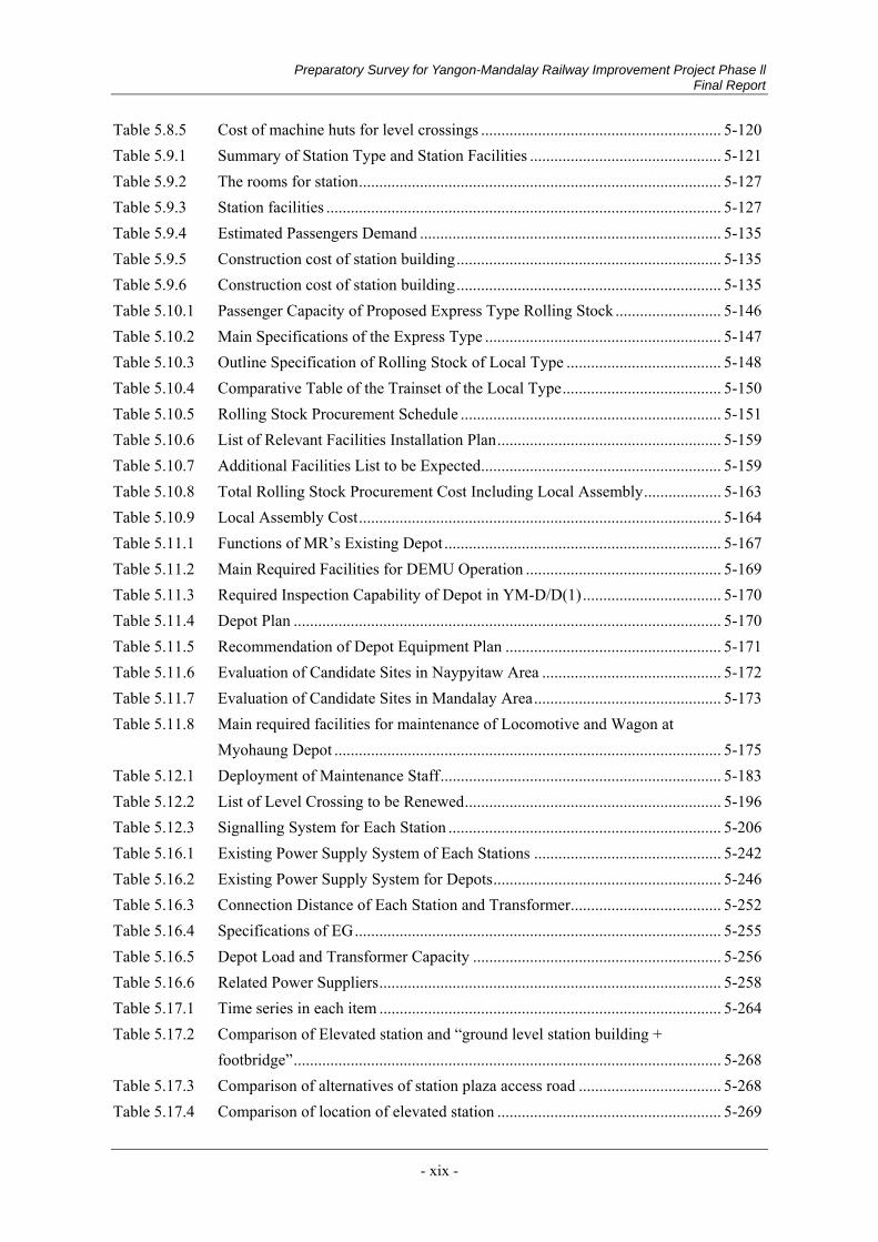
Preparatory Survey for Yangon-Mandalay Railway Improvement Project Phase ll Final Report
- xix -
Table 5.8.5 Cost of machine huts for level crossings ........................................................... 5-120 Table 5.9.1 Summary of Station Type and Station Facilities ............................................... 5-121 Table 5.9.2 The rooms for station ......................................................................................... 5-127 Table 5.9.3 Station facilities ................................................................................................. 5-127 Table 5.9.4 Estimated Passengers Demand .......................................................................... 5-135 Table 5.9.5 Construction cost of station building ................................................................. 5-135 Table 5.9.6 Construction cost of station building ................................................................. 5-135 Table 5.10.1 Passenger Capacity of Proposed Express Type Rolling Stock .......................... 5-146 Table 5.10.2 Main Specifications of the Express Type .......................................................... 5-147 Table 5.10.3 Outline Specification of Rolling Stock of Local Type ...................................... 5-148 Table 5.10.4 Comparative Table of the Trainset of the Local Type ....................................... 5-150 Table 5.10.5 Rolling Stock Procurement Schedule ................................................................ 5-151 Table 5.10.6 List of Relevant Facilities Installation Plan ....................................................... 5-159 Table 5.10.7 Additional Facilities List to be Expected ........................................................... 5-159 Table 5.10.8 Total Rolling Stock Procurement Cost Including Local Assembly ................... 5-163 Table 5.10.9 Local Assembly Cost ......................................................................................... 5-164 Table 5.11.1 Functions of MR’s Existing Depot .................................................................... 5-167 Table 5.11.2 Main Required Facilities for DEMU Operation ................................................ 5-169 Table 5.11.3 Required Inspection Capability of Depot in YM-D/D(1) .................................. 5-170 Table 5.11.4 Depot Plan ......................................................................................................... 5-170 Table 5.11.5 Recommendation of Depot Equipment Plan ..................................................... 5-171 Table 5.11.6 Evaluation of Candidate Sites in Naypyitaw Area ............................................ 5-172 Table 5.11.7 Evaluation of Candidate Sites in Mandalay Area .............................................. 5-173 Table 5.11.8 Main required facilities for maintenance of Locomotive and Wagon at
Myohaung Depot ............................................................................................... 5-175 Table 5.12.1 Deployment of Maintenance Staff ..................................................................... 5-183 Table 5.12.2 List of Level Crossing to be Renewed ............................................................... 5-196 Table 5.12.3 Signalling System for Each Station ................................................................... 5-206 Table 5.16.1 Existing Power Supply System of Each Stations .............................................. 5-242 Table 5.16.2 Existing Power Supply System for Depots ........................................................ 5-246 Table 5.16.3 Connection Distance of Each Station and Transformer ..................................... 5-252 Table 5.16.4 Specifications of EG .......................................................................................... 5-255 Table 5.16.5 Depot Load and Transformer Capacity ............................................................. 5-256 Table 5.16.6 Related Power Suppliers .................................................................................... 5-258 Table 5.17.1 Time series in each item .................................................................................... 5-264 Table 5.17.2 Comparison of Elevated station and “ground level station building +
footbridge” ......................................................................................................... 5-268 Table 5.17.3 Comparison of alternatives of station plaza access road ................................... 5-268 Table 5.17.4 Comparison of location of elevated station ....................................................... 5-269
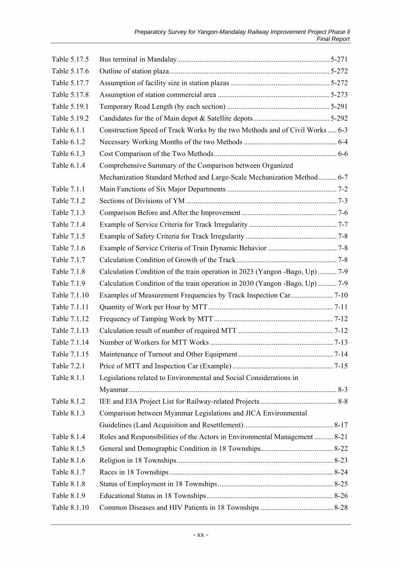
Preparatory Survey for Yangon-Mandalay Railway Improvement Project Phase ll Final Report
- xx -
Table 5.17.5 Bus terminal in Mandalay .................................................................................. 5-271 Table 5.17.6 Outline of station plaza ...................................................................................... 5-272 Table 5.17.7 Assumption of facility size in station plazas ..................................................... 5-272 Table 5.17.8 Assumption of station commercial area ............................................................ 5-273 Table 5.19.1 Temporary Road Length (by each section) ....................................................... 5-291 Table 5.19.2 Candidates for the of Main depot & Satellite depots ......................................... 5-292 Table 6.1.1 Construction Speed of Track Works by the two Methods and of Civil Works ..... 6-3 Table 6.1.2 Necessary Working Months of the two Methods .................................................. 6-4 Table 6.1.3 Cost Comparison of the Two Methods .................................................................. 6-6 Table 6.1.4 Comprehensive Summary of the Comparison between Organized
Mechanization Standard Method and Large-Scale Mechanization Method .......... 6-7 Table 7.1.1 Main Functions of Six Major Departments ........................................................... 7-2 Table 7.1.2 Sections of Divisions of YM ................................................................................. 7-3 Table 7.1.3 Comparison Before and After the Improvement ................................................... 7-6 Table 7.1.4 Example of Service Criteria for Track Irregularity ............................................... 7-7 Table 7.1.5 Example of Safety Criteria for Track Irregularity ................................................. 7-8 Table 7.1.6 Example of Service Criteria of Train Dynamic Behavior ..................................... 7-8 Table 7.1.7 Calculation Condition of Growth of the Track ...................................................... 7-8 Table 7.1.8 Calculation Condition of the train operation in 2023 (Yangon -Bago, Up) .......... 7-9 Table 7.1.9 Calculation Condition of the train operation in 2030 (Yangon -Bago, Up) .......... 7-9 Table 7.1.10 Examples of Measurement Frequencies by Track Inspection Car....................... 7-10 Table 7.1.11 Quantity of Work per Hour by MTT ................................................................... 7-11 Table 7.1.12 Frequency of Tamping Work by MTT ................................................................ 7-12 Table 7.1.13 Calculation result of number of required MTT ................................................... 7-12 Table 7.1.14 Number of Workers for MTT Works .................................................................. 7-13 Table 7.1.15 Maintenance of Turnout and Other Equipment ................................................... 7-14 Table 7.2.1 Price of MTT and Inspection Car (Example) ...................................................... 7-15 Table 8.1.1 Legislations related to Environmental and Social Considerations in
Myanmar ................................................................................................................ 8-3 Table 8.1.2 IEE and EIA Project List for Railway-related Projects ......................................... 8-8 Table 8.1.3 Comparison between Myanmar Legislations and JICA Environmental
Guidelines (Land Acquisition and Resettlement) ................................................ 8-17 Table 8.1.4 Roles and Responsibilities of the Actors in Environmental Management .......... 8-21 Table 8.1.5 General and Demographic Condition in 18 Townships ....................................... 8-22 Table 8.1.6 Religion in 18 Townships .................................................................................... 8-23 Table 8.1.7 Races in 18 Townships ........................................................................................ 8-24 Table 8.1.8 Status of Employment in 18 Townships .............................................................. 8-25 Table 8.1.9 Educational Status in 18 Townships .................................................................... 8-26 Table 8.1.10 Common Diseases and HIV Patients in 18 Townships ....................................... 8-28

Preparatory Survey for Yangon-Mandalay Railway Improvement Project Phase ll Final Report
- xxi -
Table 8.1.11 Number of Available Transportation Modes in 18 Townships ........................... 8-29 Table 8.1.12 Waste Management System in Mandalay City .................................................... 8-32 Table 8.1.13 Land Use Status in 18 Townships ....................................................................... 8-41 Table 8.1.14 Protected Areas in Myanmar ............................................................................... 8-43 Table 8.1.15 Ambient Air Quality in Naypyitaw and Mandalay .............................................. 8-44 Table 8.1.16 Water Quality in Nga Leik Stream ...................................................................... 8-44 Table 8.1.17 Noise Level in Naypyitaw and Mandalay ........................................................... 8-45 Table 8.1.18 Comparison of Project Alternatives..................................................................... 8-47 Table 8.1.19 Results of Scoping ............................................................................................... 8-51 Table 8.1.20 Terms of Reference of the Environmental Survey .............................................. 8-55 Table 8.1.21 Age and Gender of the PAPs (Bridge Renovation Area) .................................... 8-56 Table 8.1.22 Age and Gender of the PAPs (Myohaung Depot Site) ........................................ 8-57 Table 8.1.23 Age and Gender of the PAPs (Alignment and Track Improvement Area) .......... 8-57 Table 8.1.24 Occupation, Income and Expenditures of the PAPs (Bridge Renovation
Areas) .................................................................................................................. 8-57 Table 8.1.25 Occupation, Income and Expenditure of the PAPs (Myohaung Depot Site) ....... 8-58 Table 8.1.26 Occupation, Income and Expenditure of the PAPs (Track Improvement
Areas) .................................................................................................................. 8-58 Table 8.1.27 Ethnicity, Religion and Educational Level of the PAPs ...................................... 8-59 Table 8.1.28 Location of Air Quality Survey ........................................................................... 8-60 Table 8.1.29 Instruments Used for Air Quality Measurement ................................................. 8-61 Table 8.1.30 Results of Ambient Air Quality Measurement .................................................... 8-63 Table 8.1.31 Humidity and Temperature at A-1, A-2 and A-3................................................. 8-68 Table 8.1.32 Location of Water Quality Sampling ................................................................... 8-68 Table 8.1.33 Instruments Used for Water Quality Measurement ............................................. 8-69 Table 8.1.34 Results of Water Quality Measurement ............................................................... 8-71 Table 8.1.35 Instruments Used for Noise Level Measurement ................................................ 8-73 Table 8.1.36 Instruments Used for Vibration Level Measurement .......................................... 8-74 Table 8.1.37 Results of Noise Level Measurement .................................................................. 8-74 Table 8.1.38 Results of Vibration Level Measurement ............................................................ 8-76 Table 8.1.39 Species Inventory List ......................................................................................... 8-80 Table 8.1.40 Bird Species in Taungoo ...................................................................................... 8-81 Table 8.1.41 Butterfly Species in Taungoo .............................................................................. 8-82 Table 8.1.42 Bird Species in Nay Pyi Taw Depot Site ............................................................. 8-83 Table 8.1.43 Butterfly Species in Nay Pyi Taw Depot Site ..................................................... 8-83 Table 8.1.44 Dragonfly Species in Nay Pyi Taw Depot Site ................................................... 8-84 Table 8.1.45 Bird Species in Myohaung Depot Site................................................................. 8-84 Table 8.1.46 Butterfly Species in Myohaung Depot Site ......................................................... 8-85 Table 8.1.47 Dragonfly Species in Myohaung Depot Site ....................................................... 8-85
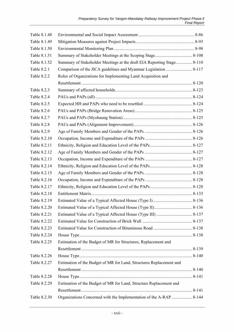
Preparatory Survey for Yangon-Mandalay Railway Improvement Project Phase ll Final Report
- xxii -
Table 8.1.48 Environmental and Social Impact Assessment .................................................... 8-86 Table 8.1.49 Mitigation Measures against Project Impacts ...................................................... 8-93 Table 8.1.50 Environmental Monitoring Plan .......................................................................... 8-98 Table 8.1.51 Summary of Stakeholder Meetings at the Scoping Stage .................................. 8-108 Table 8.1.52 Summary of Stakeholder Meetings at the draft EIA Reporting Stage ............... 8-110 Table 8.2.1 Comparison of the JICA guidelines and Myanmar Legislation ........................ 8-117 Table 8.2.2 Roles of Organizations for Implementing Land Acquisition and
Resettlement ...................................................................................................... 8-120 Table 8.2.3 Summary of affected households....................................................................... 8-123 Table 8.2.4 PAUs and PAPs (all) ......................................................................................... 8-124 Table 8.2.5 Expected HH and PAPs who need to be resettled ............................................. 8-124 Table 8.2.6 PAUs and PAPs (Bridge Renovation Areas) ..................................................... 8-125 Table 8.2.7 PAUs and PAPs (Myohaung Station) ................................................................ 8-125 Table 8.2.8 PAUs and PAPs (Alignment Improvement) ...................................................... 8-126 Table 8.2.9 Age of Family Members and Gender of the PAPs ............................................ 8-126 Table 8.2.10 Occupation, Income and Expenditure of the PAPs ........................................... 8-126 Table 8.2.11 Ethnicity, Religion and Education Level of the PAPs ....................................... 8-127 Table 8.2.12 Age of Family Members and Gender of the PAPs ............................................ 8-127 Table 8.2.13 Occupation, Income and Expenditure of the PAPs ........................................... 8-127 Table 8.2.14 Ethnicity, Religion and Education Level of the PAPs ....................................... 8-128 Table 8.2.15 Age of Family Members and Gender of the PAPs ............................................ 8-128 Table 8.2.16 Occupation, Income and Expenditure of the PAPs ........................................... 8-128 Table 8.2.17 Ethnicity, Religion and Education Level of the PAPs ....................................... 8-128 Table 8.2.18 Entitlement Matrix ............................................................................................. 8-133 Table 8.2.19 Estimated Value of a Typical Affected House (Type I) .................................... 8-136 Table 8.2.20 Estimated Value of a Typical Affected House (Type II) ................................... 8-136 Table 8.2.21 Estimated Value of a Typical Affected House (Type III) ................................. 8-137 Table 8.2.22 Estimated Value for Construction of Brick Wall .............................................. 8-137 Table 8.2.23 Estimated Value for Construction of Bituminous Road .................................... 8-138 Table 8.2.24 House Type ........................................................................................................ 8-138 Table 8.2.25 Estimation of the Budget of MR for Structures, Replacement and
Resettlement ...................................................................................................... 8-139 Table 8.2.26 House Type ........................................................................................................ 8-140 Table 8.2.27 Estimation of the Budget of MR for Land, Structures Replacement and
Resettlement ...................................................................................................... 8-140 Table 8.2.28 House Type ........................................................................................................ 8-141 Table 8.2.29 Estimation of the Budget of MR for Land, Structure Replacement and
Resettlement ...................................................................................................... 8-141 Table 8.2.30 Organizations Concerned with the Implementation of the A-RAP ................... 8-144
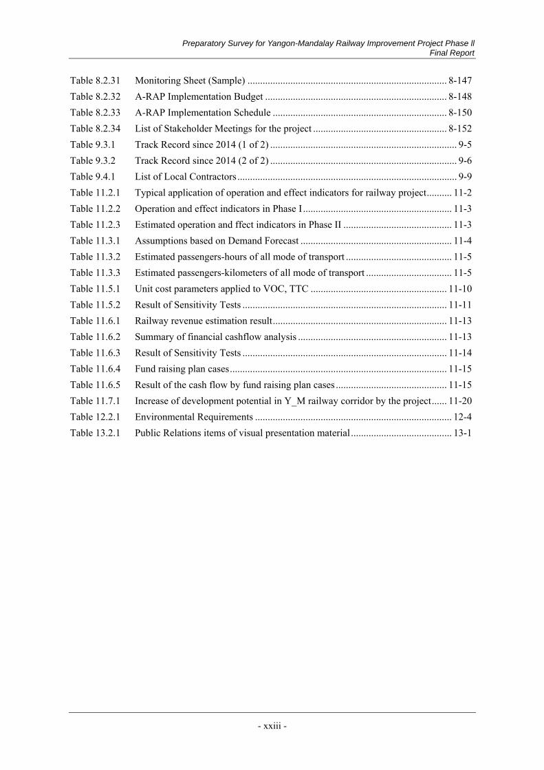
Preparatory Survey for Yangon-Mandalay Railway Improvement Project Phase ll Final Report
- xxiii -
Table 8.2.31 Monitoring Sheet (Sample) ............................................................................... 8-147 Table 8.2.32 A-RAP Implementation Budget ........................................................................ 8-148 Table 8.2.33 A-RAP Implementation Schedule ..................................................................... 8-150 Table 8.2.34 List of Stakeholder Meetings for the project ..................................................... 8-152 Table 9.3.1 Track Record since 2014 (1 of 2) .......................................................................... 9-5 Table 9.3.2 Track Record since 2014 (2 of 2) .......................................................................... 9-6 Table 9.4.1 List of Local Contractors ....................................................................................... 9-9 Table 11.2.1 Typical application of operation and effect indicators for railway project .......... 11-2 Table 11.2.2 Operation and effect indicators in Phase I ........................................................... 11-3 Table 11.2.3 Estimated operation and ffect indicators in Phase II ........................................... 11-3 Table 11.3.1 Assumptions based on Demand Forecast ............................................................ 11-4 Table 11.3.2 Estimated passengers-hours of all mode of transport .......................................... 11-5 Table 11.3.3 Estimated passengers-kilometers of all mode of transport .................................. 11-5 Table 11.5.1 Unit cost parameters applied to VOC, TTC ...................................................... 11-10 Table 11.5.2 Result of Sensitivity Tests ................................................................................. 11-11 Table 11.6.1 Railway revenue estimation result ..................................................................... 11-13 Table 11.6.2 Summary of financial cashflow analysis ........................................................... 11-13 Table 11.6.3 Result of Sensitivity Tests ................................................................................. 11-14 Table 11.6.4 Fund raising plan cases ...................................................................................... 11-15 Table 11.6.5 Result of the cash flow by fund raising plan cases ............................................ 11-15 Table 11.7.1 Increase of development potential in Y_M railway corridor by the project ...... 11-20 Table 12.2.1 Environmental Requirements .............................................................................. 12-4 Table 13.2.1 Public Relations items of visual presentation material ........................................ 13-1
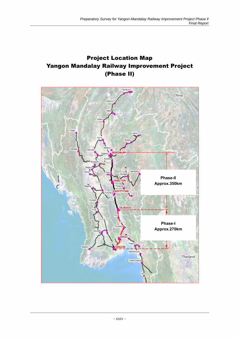
Preparatory Survey for Yangon-Mandalay Railway Improvement Project Phase ll Final Report
- xxiv -
Project Location Map
Yangon Mandalay Railway Improvement Project (Phase II)
Phase-I Approx.270km
Phase-II Approx.350km
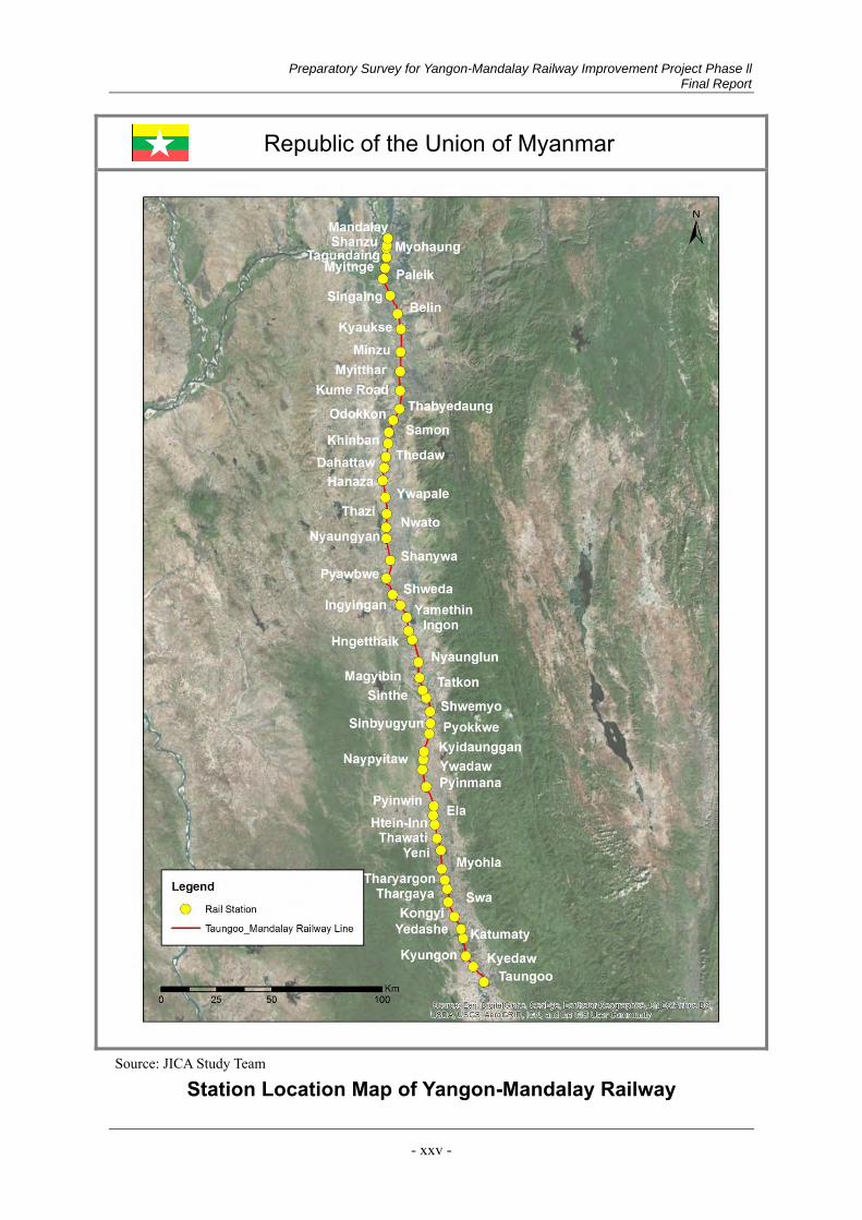
Preparatory Survey for Yangon-Mandalay Railway Improvement Project Phase ll Final Report
- xxv -
Source: JICA Study Team
Station Location Map of Yangon-Mandalay Railway
Republic of the Union of Myanmar
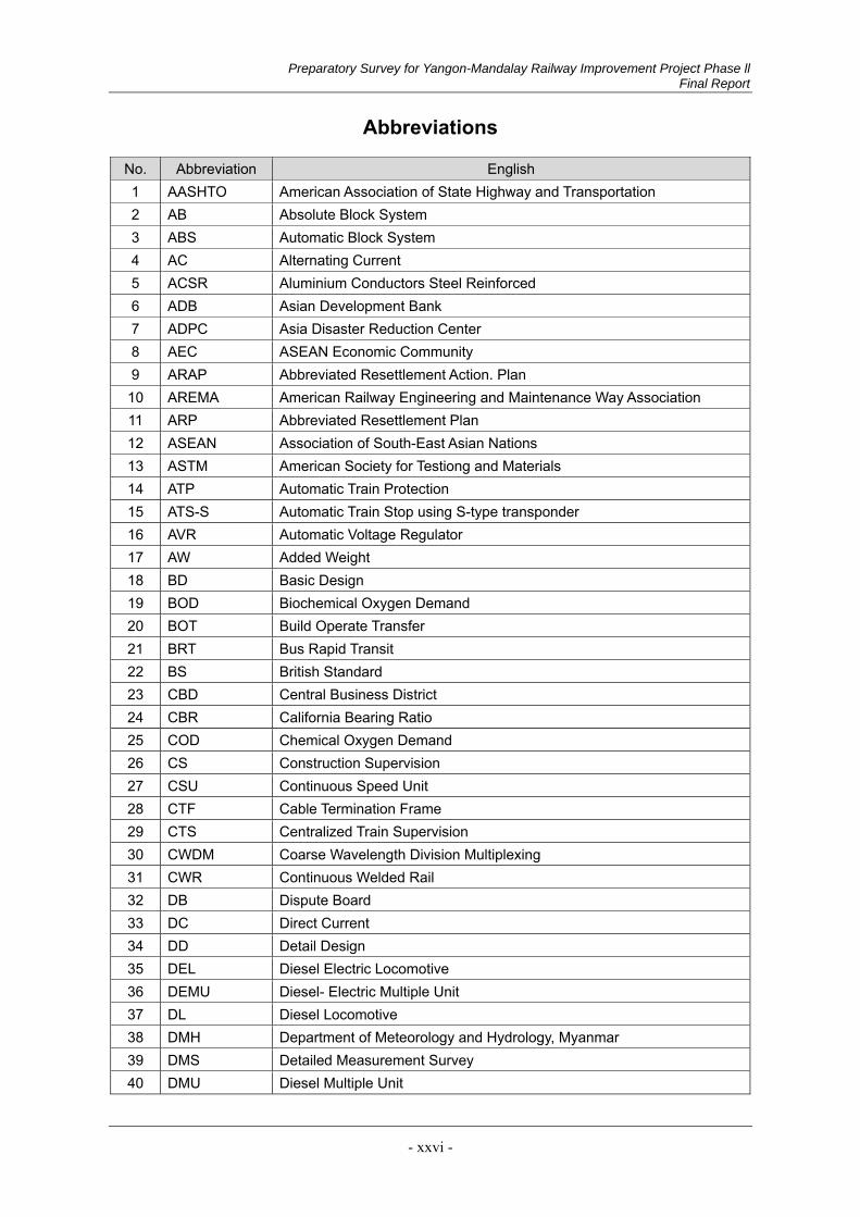
Preparatory Survey for Yangon-Mandalay Railway Improvement Project Phase ll Final Report
- xxvi -
Abbreviations
No. Abbreviation English 1 AASHTO American Association of State Highway and Transportation 2 AB Absolute Block System 3 ABS Automatic Block System 4 AC Alternating Current 5 ACSR Aluminium Conductors Steel Reinforced 6 ADB Asian Development Bank 7 ADPC Asia Disaster Reduction Center 8 AEC ASEAN Economic Community 9 ARAP Abbreviated Resettlement Action. Plan 10 AREMA American Railway Engineering and Maintenance Way Association 11 ARP Abbreviated Resettlement Plan 12 ASEAN Association of South-East Asian Nations 13 ASTM American Society for Testiong and Materials 14 ATP Automatic Train Protection 15 ATS-S Automatic Train Stop using S-type transponder 16 AVR Automatic Voltage Regulator 17 AW Added Weight 18 BD Basic Design 19 BOD Biochemical Oxygen Demand 20 BOT Build Operate Transfer 21 BRT Bus Rapid Transit 22 BS British Standard 23 CBD Central Business District 24 CBR California Bearing Ratio 25 COD Chemical Oxygen Demand 26 CS Construction Supervision 27 CSU Continuous Speed Unit 28 CTF Cable Termination Frame 29 CTS Centralized Train Supervision 30 CWDM Coarse Wavelength Division Multiplexing 31 CWR Continuous Welded Rail 32 DB Dispute Board 33 DC Direct Current 34 DD Detail Design 35 DEL Diesel Electric Locomotive 36 DEMU Diesel- Electric Multiple Unit 37 DL Diesel Locomotive 38 DMH Department of Meteorology and Hydrology, Myanmar 39 DMS Detailed Measurement Survey 40 DMU Diesel Multiple Unit
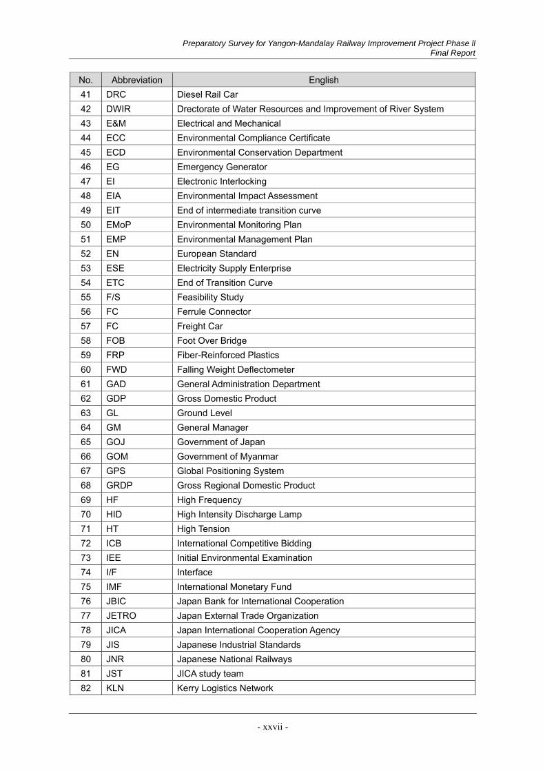
Preparatory Survey for Yangon-Mandalay Railway Improvement Project Phase ll Final Report
- xxvii -
No. Abbreviation English 41 DRC Diesel Rail Car 42 DWIR Drectorate of Water Resources and Improvement of River System 43 E&M Electrical and Mechanical 44 ECC Environmental Compliance Certificate 45 ECD Environmental Conservation Department 46 EG Emergency Generator 47 EI Electronic Interlocking 48 EIA Environmental Impact Assessment 49 EIT End of intermediate transition curve 50 EMoP Environmental Monitoring Plan 51 EMP Environmental Management Plan 52 EN European Standard 53 ESE Electricity Supply Enterprise 54 ETC End of Transition Curve 55 F/S Feasibility Study 56 FC Ferrule Connector 57 FC Freight Car 58 FOB Foot Over Bridge 59 FRP Fiber-Reinforced Plastics 60 FWD Falling Weight Deflectometer 61 GAD General Administration Department 62 GDP Gross Domestic Product 63 GL Ground Level 64 GM General Manager 65 GOJ Government of Japan 66 GOM Government of Myanmar 67 GPS Global Positioning System 68 GRDP Gross Regional Domestic Product 69 HF High Frequency 70 HID High Intensity Discharge Lamp 71 HT High Tension 72 ICB International Competitive Bidding 73 IEE Initial Environmental Examination 74 I/F Interface 75 IMF International Monetary Fund 76 JBIC Japan Bank for International Cooperation 77 JETRO Japan External Trade Organization 78 JICA Japan International Cooperation Agency 79 JIS Japanese Industrial Standards 80 JNR Japanese National Railways 81 JST JICA study team 82 KLN Kerry Logistics Network
Preparatory Survey for Yangon-Mandalay Railway Improvement Project Phase ll Final Report
- xxviii -
No. Abbreviation English 83 LC Level Crossing 84 LED Light Emitting Diode 85 LO Lubricating Oil 86 LRT Light Rail Transit 87 LTE Long Term Evolution(high speed wireless communication standard) 88 MARS Multi Access seat Reservation System 89 MD Managing Director 90 MDB Multilateral Development Bank 91 MEC Myanmar Earthquake Commitee 92 MEPE Myanmar Electric Power Enterprise 93 MESC Mandalay Electricity Supply Corporation 94 METI Ministry of Economy, Trade and Industry 95 MGS Myanmar Geosciences Society 96 MIMU Myanmar Information Management Unit 97 ML Main Line 98 MLIT Ministry of Land, Infrastructure, Transport and Tourism, Japan 99 MM Main Motor 100 MMI Man Machine Interface 101 MMK Myanmar Kyat 102 MNBC Myanmar National Building Codes 103 MOALI Ministry of Agriculture, Livestock and Irrigation 104 MOC Ministry of Construction 105 MONREC Ministry of Natural Resourse and Environmental Conservation 106 MOTC Ministry of Transportation and Communicatoins 107 MPPE Myanmar Petroleum Product Enterprise 108 MR Myanma Railways 109 MSH Main Signal House 110 MYT Myanmar’s National Transport Master Plan 111 NEQ National Environmental Quality Guidelines 112 NLTC Non-on-load Tap Changer 113 NTP Notice to Proceed 114 O&M Operation & Maintenance 115 OCC Operation Control Center
116 OCC Project The Project for Installation of Operation Control Centre System and Safety Equipment
117 OCHA United Nations Office for Coordination of Humanitarian Affairs 118 ODA Official Development Assistance 119 OECD Organization for Economic Co-operation and Development 120 OFC Optical Fiber Cable 121 OLTC 122 OTC Overhead Traveling Crane 123 OTDR Optical Time Domain Reflectometer
Preparatory Survey for Yangon-Mandalay Railway Improvement Project Phase ll Final Report
- xxix -
No. Abbreviation English 124 P/Q Pre-Qualification 125 PAPs Project Affected Persons 126 PAUs Project Affected Units 127 PC Prestressed Concrete 128 PGA Peak Ground Acceleration 129 PGD Peak Ground Displacement 130 PGV Peak Ground Velocity 131 PMU Project Management Unit 132 PPP Public-Private Partnership 133 PSHA Probabilistic Seismic Hazard Analysis 134 PIS Passenger Information System 135 PVC Poly Vinyl Chloride 136 PWM Pulse Width Modulation
137 QA and QC Plan Quality Assurance and Quality Control Plan
138 RBE Rail Bus Engine 139 RC Reinforced Concrete 140 Rf Rectifier 141 RGL Resources Group Logistics 142 RH Relay Hut 143 RI Relay Interlocking 144 ROB Road Over Bridge 145 ROW Right of Way 146 SA Spectal Acceleration 147 SAC Spaced Aerial Cable 148 SBD Standard Bidding Documents 149 SC Scissors crossing 150 SDR Social Discount Rate 151 SIL Safety Integrity Level 152 SL Survey Center line 153 SM Single Mode 154 SPAD Signal Passed At Danger 155 SPT Standard Penetration Test 156 SSI Solid State Interlocking 157 STEP Special Terms for Economic Partnership 158 STM Synchronous Transfer Mode 159 SW Switch 160 T/C Technical Committee 161 TA Tender Assistance 162 TAC Technical Advisory Committee 163 TCL Transition Curve Length 164 TEU Twenty Foot Equivalent Unit
Preparatory Survey for Yangon-Mandalay Railway Improvement Project Phase ll Final Report
- xxx -
No. Abbreviation English 165 TID Train Information Display 166 TMS Train Monitoring System 167 TN Turnout 168 T-N Total Nitrogen 169 TOD Transit Oriented Development 170 T-P Total Phosphorus 171 TRS Ticket Reservation System 172 UHF Ultra High Frequency 173 UIC International Union of Railways 174 UPS Uninterruptible Power Supply 175 VAT Value Added Tax 176 VHF Very High Frequency 177 VR Variable Resistance 178 YCDC Yangon City Development Committee 179 YCR Yangon Circular Railway 180 YCR-F/S Feasibility Study of the Yangon Circular Railway Line Upgrading Project
181 YCR-MR/BD Supporting Consulting Services for the Yangon Circular Railway Upgrading Project (for MR Works)
182 YCR-RS/BD Basic Design Study of the Yangon Circular Railway Line Upgrading Project
183 YESC Yangon Electricity Supply Corporation 184 YM Yangon-Mandalay Railway
185 YM-D/D(1) Detailed Design for Yangon-Mandalay Railway Improvement Project Phase I
186 YM(1)-F/S Feasibility Study on the Rehabilitation and Modernization of Yangon–Mandalay Railway
187 YUTRA Comprehensive Urban Transport Master Plan of the Greater Yangon
Preparatory Survey for Yangon-Mandalay Railway Improvement Project Phase ll Final Report
- xxxi -
Station Name (Phase I)
NO STATION NAME KILOPOST MILEAGE
1 Yangon 0 0
2 Pazundaung 1.61 1
3 Mahlwagon 4.02 2.5
4 Thin gan gyun 7.24 4.5
5 Toegyaungkalay 11.67 7.25
6 Ywathagyi 20.52 12.75
7 Laydaungkan 25.75 16
8 Darbain 36.15 22.46
9 Tongyi 48.68 30.25
10 Kyauktan 55.12 34.25
11 Tawa 61.56 38.25
12 Payathonzu 68.4 42.5
13 Bago 74.83 46.5
14 Shwele 83.24 51.72
15 Payagyi 91.73 57
16 Pyinbongyi 104.12 64.7
17 Kadok 114.26 71
18 Paungdawthi 121.91 75.75
19 Eimshaylayse 126 78.75
20 Daiku 130.76 81.25
21 Pyuntaza 141.22 87.75
22 Nyaung le bin 149.27 97.47
23 Tawwi 156.86 97.47
24 Pein za lok 163.75 101.75
25 Tha tegon 170.59 106
26 Kyauktaga 175.02 108.75
27 Penwegon 183.87 114.25
28 Taw gywe in 191.51 119

Preparatory Survey for Yangon-Mandalay Railway Improvement Project Phase ll Final Report
- xxxii -
NO STATION NAME KILOPOST MILEAGE
29 Kanyutk win 199.08 123.7
30 Nyaung bintha 206.8 128.5
31 Pyu 216.05 134.25
32 Zeya wadi 222.49 138.25
33 Nyaungchidauk 230.54 143.25
34 Kywebwe 240.19 149.25
35 Banbwegon 245.83 152.75
36 Oktwin 254.68 158.25
37 Thaung dai gon 260.31 161.75
38 Taungoo 267.15 166
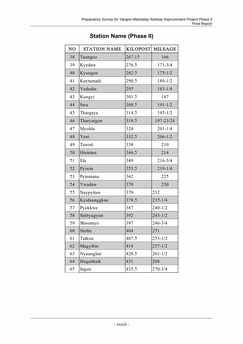
Preparatory Survey for Yangon-Mandalay Railway Improvement Project Phase ll Final Report
- xxxiii -
Station Name (Phase II)
NO STATION NAME KILOPOST MILEAGE
38 Taungoo 267.15 166
39 Kyedaw 276.5 171-3/4
40 Kyungon 282.5 175-1/2
41 Kaytumadi 290.5 180-1/2
42 Yedashe 295 183-1/4
43 Kongyi 301.5 187
44 Swa 308.5 191-1/2
45 Thargaya 314.5 195-1/2
46 Tharyargon 318.5 197-23/24
47 Myohla 324 201-1/4
48 Yeni 332.5 206-1/2
49 Tawuti 338 210
50 Hteininn 344.5 214
51 Ela 349 216-3/4
52 Pyiwin 353.5 219-1/4
53 Pyinmana 362 225
54 Ywadaw 370 230
55 Naypyitaw 370 232
56 Kyidaunggkan 378.5 235-1/4
57 Pyokkwe 387 240-1/2
58 Sinbyugyun 392 243-1/2
59 Shwemyo 397 246-3/4
60 Sinthe 404 251
61 Tatkon 407.5 253-1/2
62 Magyibin 414 257-1/2
63 Nyaunglun 420.5 261-1/2
64 Hngetthaik 431 268
65 Ingon 435.5 270-3/4
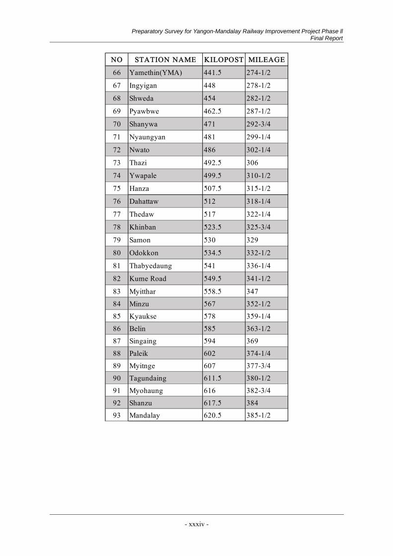
Preparatory Survey for Yangon-Mandalay Railway Improvement Project Phase ll Final Report
- xxxiv -
NO STATION NAME KILOPOST MILEAGE
66 Yamethin(YMA) 441.5 274-1/2
67 Ingyigan 448 278-1/2
68 Shweda 454 282-1/2
69 Pyawbwe 462.5 287-1/2
70 Shanywa 471 292-3/4
71 Nyaungyan 481 299-1/4
72 Nwato 486 302-1/4
73 Thazi 492.5 306
74 Ywapale 499.5 310-1/2
75 Hanza 507.5 315-1/2
76 Dahattaw 512 318-1/4
77 Thedaw 517 322-1/4
78 Khinban 523.5 325-3/4
79 Samon 530 329
80 Odokkon 534.5 332-1/2
81 Thabyedaung 541 336-1/4
82 Kume Road 549.5 341-1/2
83 Myitthar 558.5 347
84 Minzu 567 352-1/2
85 Kyaukse 578 359-1/4
86 Belin 585 363-1/2
87 Singaing 594 369
88 Paleik 602 374-1/4
89 Myitnge 607 377-3/4
90 Tagundaing 611.5 380-1/2
91 Myohaung 616 382-3/4
92 Shanzu 617.5 384
93 Mandalay 620.5 385-1/2
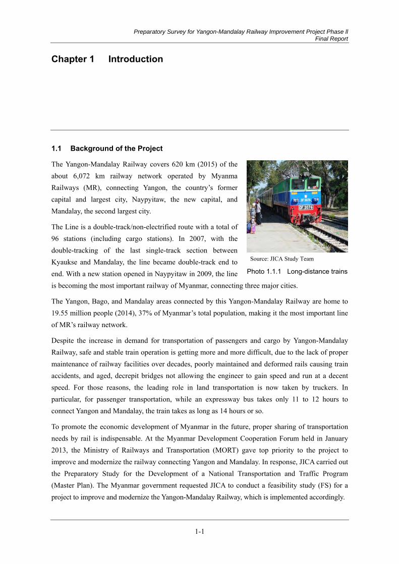
Preparatory Survey for Yangon-Mandalay Railway Improvement Project Phase ll Final Report
1-1
Chapter 1 Introduction
1.1 Background of the Project
The Yangon-Mandalay Railway covers 620 km (2015) of the about 6,072 km railway network operated by Myanma Railways (MR), connecting Yangon, the country’s former capital and largest city, Naypyitaw, the new capital, and Mandalay, the second largest city.
The Line is a double-track/non-electrified route with a total of 96 stations (including cargo stations). In 2007, with the double-tracking of the last single-track section between Kyaukse and Mandalay, the line became double-track end to end. With a new station opened in Naypyitaw in 2009, the line is becoming the most important railway of Myanmar, connecting three major cities.
The Yangon, Bago, and Mandalay areas connected by this Yangon-Mandalay Railway are home to 19.55 million people (2014), 37% of Myanmar’s total population, making it the most important line of MR’s railway network.
Despite the increase in demand for transportation of passengers and cargo by Yangon-Mandalay Railway, safe and stable train operation is getting more and more difficult, due to the lack of proper maintenance of railway facilities over decades, poorly maintained and deformed rails causing train accidents, and aged, decrepit bridges not allowing the engineer to gain speed and run at a decent speed. For those reasons, the leading role in land transportation is now taken by truckers. In particular, for passenger transportation, while an expressway bus takes only 11 to 12 hours to connect Yangon and Mandalay, the train takes as long as 14 hours or so.
To promote the economic development of Myanmar in the future, proper sharing of transportation needs by rail is indispensable. At the Myanmar Development Cooperation Forum held in January 2013, the Ministry of Railways and Transportation (MORT) gave top priority to the project to improve and modernize the railway connecting Yangon and Mandalay. In response, JICA carried out the Preparatory Study for the Development of a National Transportation and Traffic Program (Master Plan). The Myanmar government requested JICA to conduct a feasibility study (FS) for a project to improve and modernize the Yangon-Mandalay Railway, which is implemented accordingly.
Source: JICA Study Team
Photo 1.1.1 Long-distance trains
Preparatory Survey for Yangon-Mandalay Railway Improvement Project Phase ll Final Report
1-2
The feasibility study concluded that the government should give top priority to a project to improve and modernize the arterial railway from the viewpoints of national economy and fiscal revenues. Accordingly, an ODA loan agreement for the Phase I project was concluded in September 2014 in order to renew and modernize the transportation facilities and equipment along the Yangon-Taungoo section of the Yangon- Mandalay railway. Regarding the Phase I project currently under way, the detailed design study has already been completed, and MR is currently procuring contractors
The Yangon-Mandalay Railway Improvement Project is in line with what both the Japanese government and Myanmar government aim at, i.e., “the support of infrastructure development necessary for sustainable economic growth”, one of the priority areas in Japan’s Policy for Economic Cooperation to Myanmar (April 2012) and the rapid development of basic economic infrastructure, as one of the major objectives of the “Economic Policy” (July 2016) of the National League for Democracy (NLD), which recently came to power in the country.
The Study was triggered by a request from the Minister of Transport and Communications of Myanmar to early complete the renovation of the Yangon-Mandalay Railway as a whole, defining the improvement of the Taungoo-Mandalay section as a Phase II project and prompting it as a study necessary for the examination of the Yangon-Mandalay Railway Improvement Project Phase II (the Project).
1.2 Purpose of the Project
The objectives of this project are to rehabilitate deteriorated infrastructures and relevant facilities of the existing railway between Yangon city and Mandalay city and modernize them to increase the safety and speed of train operation, to reduce transportation cost, and to increase passenger and freight transportation, which will all contribute to the national economic development and the betterment of quality of life of the residents. The proposed technical targets of this project are to achieve the maximum train running speed of 100 km/h safely and to provide the train operation service of less than 8 hours for the section from Yangon to Mandalay.
Outline of the Project is shown below:
1) Civil Works including track works, civil structures and station buildings
2) Upgrade of signalling and telecommunication system
3) Introduction of new rolling stocks (DEMU)
4) Improvement of Freight Facilities
5) Improvement of Passenger Service Equipment including Automatic Ticket Bending Machine
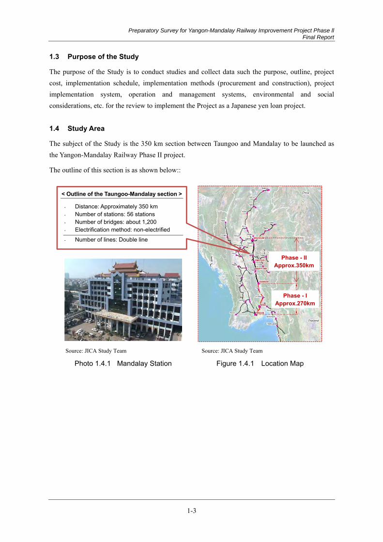
Preparatory Survey for Yangon-Mandalay Railway Improvement Project Phase ll Final Report
1-3
1.3 Purpose of the Study
The purpose of the Study is to conduct studies and collect data such the purpose, outline, project cost, implementation schedule, implementation methods (procurement and construction), project implementation system, operation and management systems, environmental and social considerations, etc. for the review to implement the Project as a Japanese yen loan project.
1.4 Study Area
The subject of the Study is the 350 km section between Taungoo and Mandalay to be launched as the Yangon-Mandalay Railway Phase II project.
The outline of this section is as shown below::
Source: JICA Study Team
Photo 1.4.1 Mandalay Station
Source: JICA Study Team
Figure 1.4.1 Location Map
Phase - I Approx.270km
Phase - II Approx.350km
< Outline of the Taungoo-Mandalay section >
- Distance: Approximately 350 km
- Number of stations: 56 stations
- Number of bridges: about 1,200
- Electrification method: non-electrified
- Number of lines: Double line
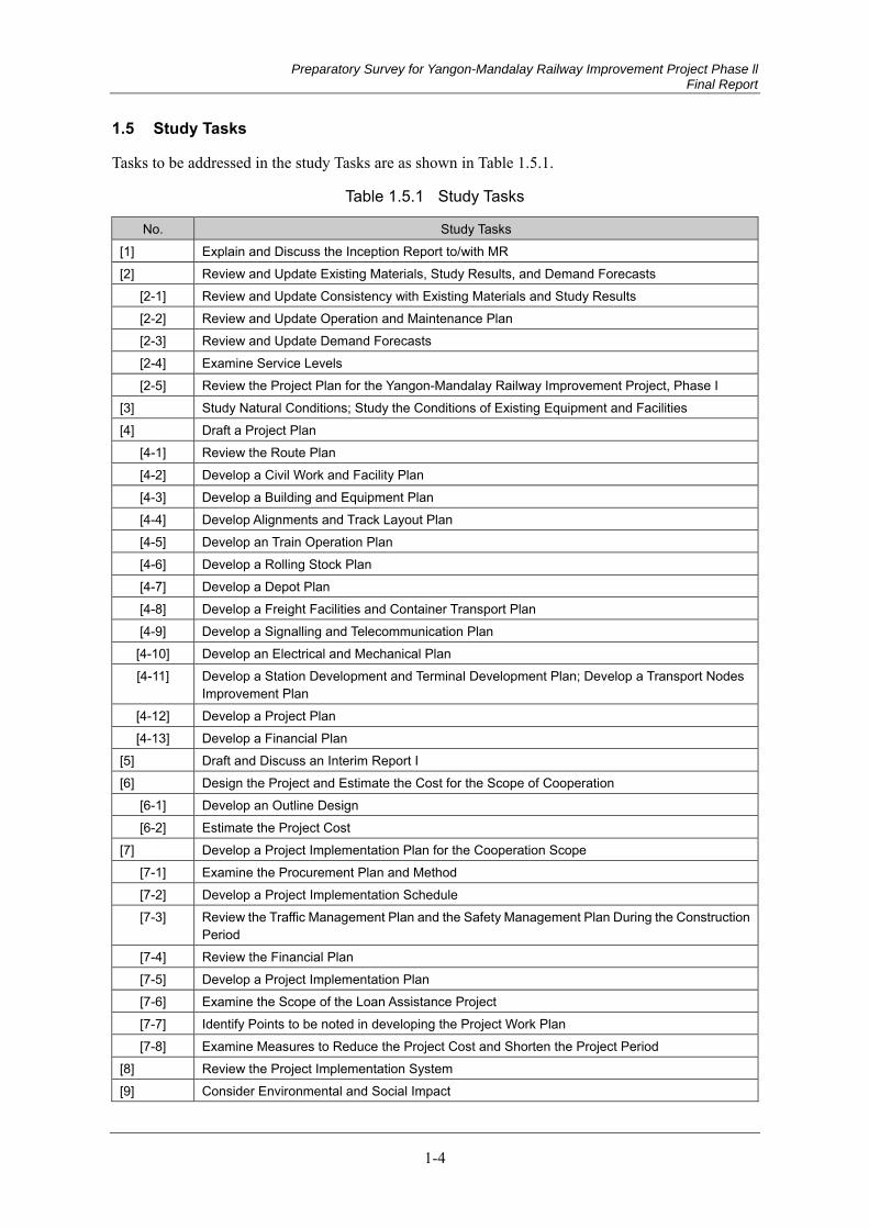
Preparatory Survey for Yangon-Mandalay Railway Improvement Project Phase ll Final Report
1-4
1.5 Study Tasks
Tasks to be addressed in the study Tasks are as shown in Table 1.5.1.
Table 1.5.1 Study Tasks
No. Study Tasks [1] Explain and Discuss the Inception Report to/with MR [2] Review and Update Existing Materials, Study Results, and Demand Forecasts
[2-1] Review and Update Consistency with Existing Materials and Study Results [2-2] Review and Update Operation and Maintenance Plan [2-3] Review and Update Demand Forecasts [2-4] Examine Service Levels [2-5] Review the Project Plan for the Yangon-Mandalay Railway Improvement Project, Phase I
[3] Study Natural Conditions; Study the Conditions of Existing Equipment and Facilities [4] Draft a Project Plan
[4-1] Review the Route Plan [4-2] Develop a Civil Work and Facility Plan [4-3] Develop a Building and Equipment Plan [4-4] Develop Alignments and Track Layout Plan [4-5] Develop an Train Operation Plan [4-6] Develop a Rolling Stock Plan [4-7] Develop a Depot Plan [4-8] Develop a Freight Facilities and Container Transport Plan [4-9] Develop a Signalling and Telecommunication Plan
[4-10] Develop an Electrical and Mechanical Plan [4-11] Develop a Station Development and Terminal Development Plan; Develop a Transport Nodes
Improvement Plan [4-12] Develop a Project Plan [4-13] Develop a Financial Plan
[5] Draft and Discuss an Interim Report I [6] Design the Project and Estimate the Cost for the Scope of Cooperation
[6-1] Develop an Outline Design [6-2] Estimate the Project Cost
[7] Develop a Project Implementation Plan for the Cooperation Scope [7-1] Examine the Procurement Plan and Method [7-2] Develop a Project Implementation Schedule [7-3] Review the Traffic Management Plan and the Safety Management Plan During the Construction
Period [7-4] Review the Financial Plan [7-5] Develop a Project Implementation Plan [7-6] Examine the Scope of the Loan Assistance Project [7-7] Identify Points to be noted in developing the Project Work Plan [7-8] Examine Measures to Reduce the Project Cost and Shorten the Project Period
[8] Review the Project Implementation System [9] Consider Environmental and Social Impact
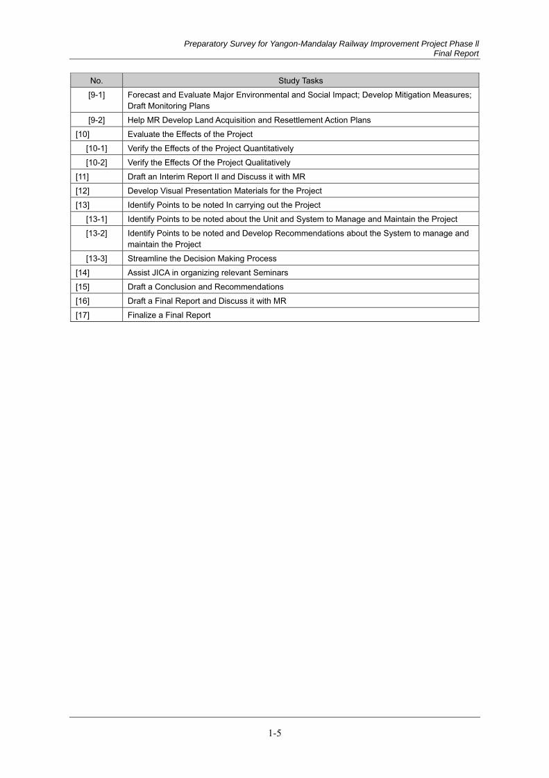
Preparatory Survey for Yangon-Mandalay Railway Improvement Project Phase ll Final Report
1-5
No. Study Tasks [9-1] Forecast and Evaluate Major Environmental and Social Impact; Develop Mitigation Measures;
Draft Monitoring Plans [9-2] Help MR Develop Land Acquisition and Resettlement Action Plans
[10] Evaluate the Effects of the Project [10-1] Verify the Effects of the Project Quantitatively [10-2] Verify the Effects Of the Project Qualitatively
[11] Draft an Interim Report II and Discuss it with MR [12] Develop Visual Presentation Materials for the Project [13] Identify Points to be noted In carrying out the Project
[13-1] Identify Points to be noted about the Unit and System to Manage and Maintain the Project [13-2] Identify Points to be noted and Develop Recommendations about the System to manage and
maintain the Project [13-3] Streamline the Decision Making Process
[14] Assist JICA in organizing relevant Seminars [15] Draft a Conclusion and Recommendations [16] Draft a Final Report and Discuss it with MR [17] Finalize a Final Report
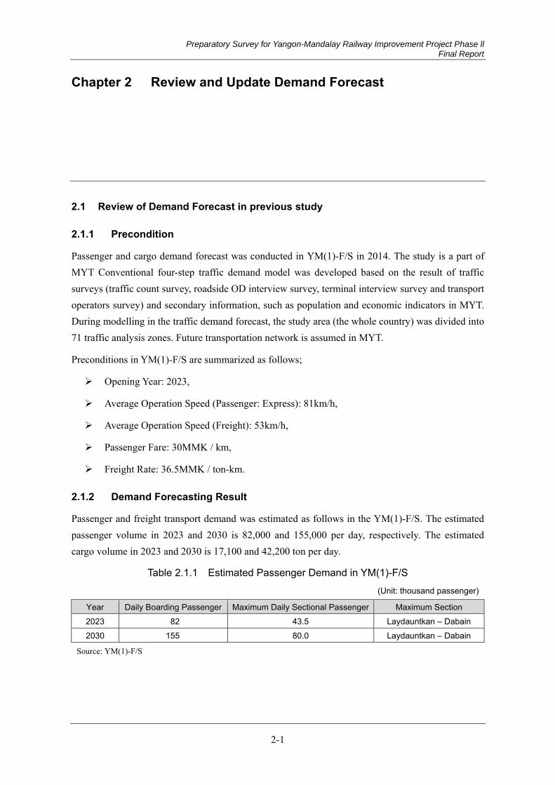
Preparatory Survey for Yangon-Mandalay Railway Improvement Project Phase ll Final Report
2-1
Chapter 2 Review and Update Demand Forecast
2.1 Review of Demand Forecast in previous study
Precondition 2.1.1
Passenger and cargo demand forecast was conducted in YM(1)-F/S in 2014. The study is a part of MYT Conventional four-step traffic demand model was developed based on the result of traffic surveys (traffic count survey, roadside OD interview survey, terminal interview survey and transport operators survey) and secondary information, such as population and economic indicators in MYT. During modelling in the traffic demand forecast, the study area (the whole country) was divided into 71 traffic analysis zones. Future transportation network is assumed in MYT.
Preconditions in YM(1)-F/S are summarized as follows;
Opening Year: 2023,
Average Operation Speed (Passenger: Express): 81km/h,
Average Operation Speed (Freight): 53km/h,
Passenger Fare: 30MMK / km,
Freight Rate: 36.5MMK / ton-km.
Demand Forecasting Result 2.1.2
Passenger and freight transport demand was estimated as follows in the YM(1)-F/S. The estimated passenger volume in 2023 and 2030 is 82,000 and 155,000 per day, respectively. The estimated cargo volume in 2023 and 2030 is 17,100 and 42,200 ton per day.
Table 2.1.1 Estimated Passenger Demand in YM(1)-F/S
(Unit: thousand passenger)
Year Daily Boarding Passenger Maximum Daily Sectional Passenger Maximum Section 2023 82 43.5 Laydauntkan – Dabain 2030 155 80.0 Laydauntkan – Dabain
Source: YM(1)-F/S
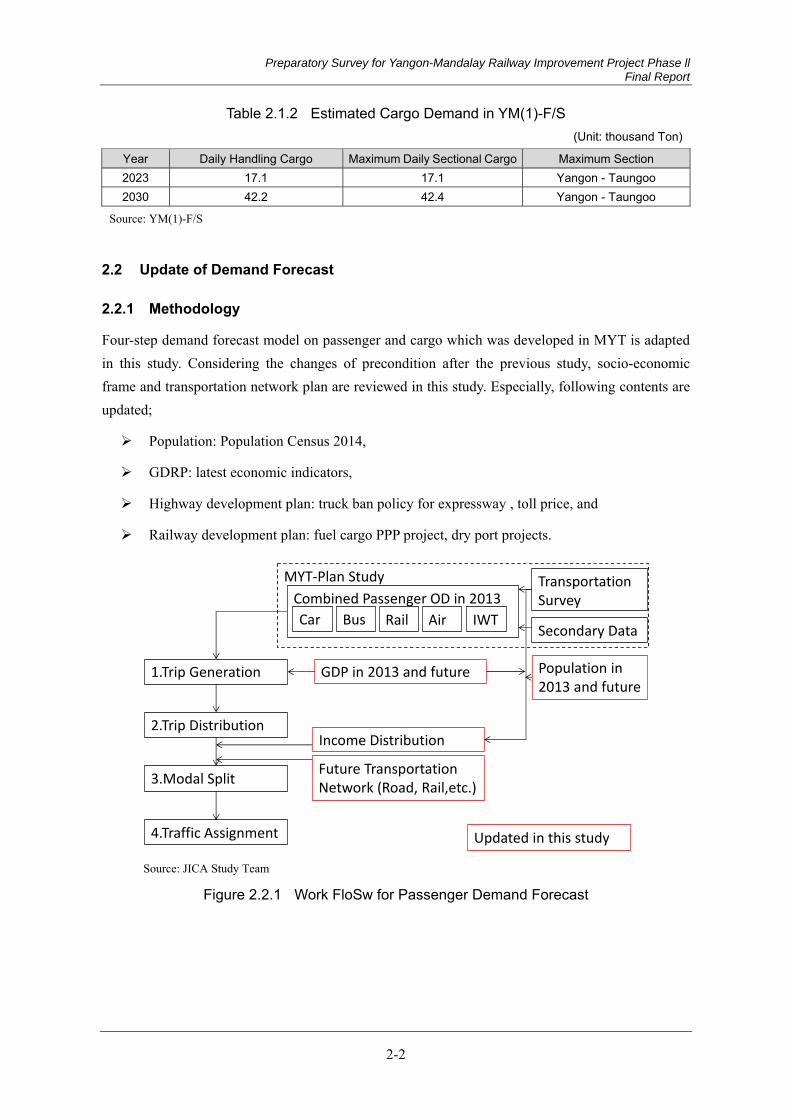
Preparatory Survey for Yangon-Mandalay Railway Improvement Project Phase ll Final Report
2-2
Table 2.1.2 Estimated Cargo Demand in YM(1)-F/S (Unit: thousand Ton)
Year Daily Handling Cargo Maximum Daily Sectional Cargo Maximum Section 2023 17.1 17.1 Yangon - Taungoo 2030 42.2 42.4 Yangon - Taungoo
Source: YM(1)-F/S
2.2 Update of Demand Forecast
Methodology 2.2.1
Four-step demand forecast model on passenger and cargo which was developed in MYT is adapted in this study. Considering the changes of precondition after the previous study, socio-economic frame and transportation network plan are reviewed in this study. Especially, following contents are updated;
Population: Population Census 2014,
GDRP: latest economic indicators,
Highway development plan: truck ban policy for expressway , toll price, and
Railway development plan: fuel cargo PPP project, dry port projects.
Source: JICA Study Team
Figure 2.2.1 Work FloSw for Passenger Demand Forecast
Combined Passenger OD in 2013
1.Trip Generation
2.Trip Distribution
3.Modal Split
4.Traffic Assignment
Car Bus AirRail IWT
Transportation Survey
Secondary Data
GDP in 2013 and future
Income Distribution
Future TransportationNetwork (Road, Rail,etc.)
MYT-Plan Study
Population in 2013 and future
Updated in this study
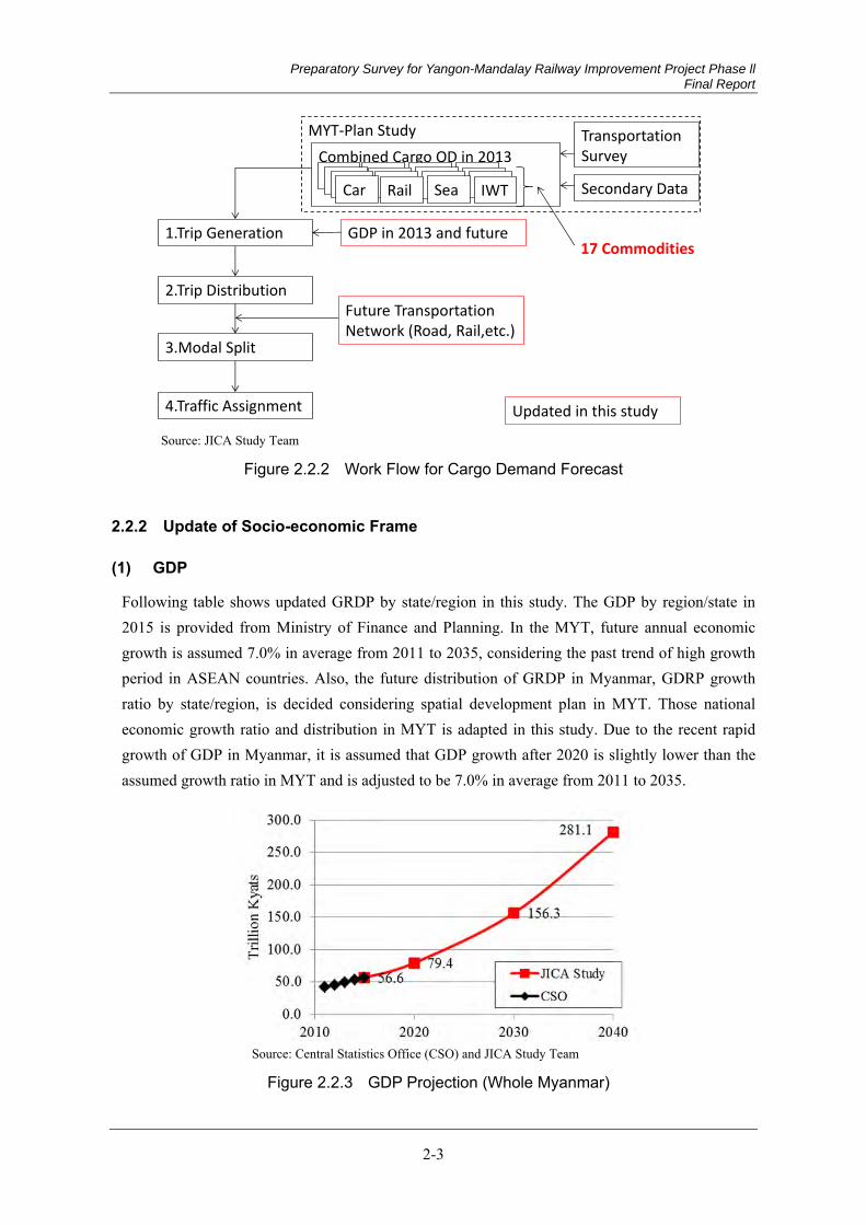
Preparatory Survey for Yangon-Mandalay Railway Improvement Project Phase ll Final Report
2-3
Source: JICA Study Team
Figure 2.2.2 Work Flow for Cargo Demand Forecast
Update of Socio-economic Frame 2.2.2
GDP (1)
Following table shows updated GRDP by state/region in this study. The GDP by region/state in 2015 is provided from Ministry of Finance and Planning. In the MYT, future annual economic growth is assumed 7.0% in average from 2011 to 2035, considering the past trend of high growth period in ASEAN countries. Also, the future distribution of GRDP in Myanmar, GDRP growth ratio by state/region, is decided considering spatial development plan in MYT. Those national economic growth ratio and distribution in MYT is adapted in this study. Due to the recent rapid growth of GDP in Myanmar, it is assumed that GDP growth after 2020 is slightly lower than the assumed growth ratio in MYT and is adjusted to be 7.0% in average from 2011 to 2035.
Source: Central Statistics Office (CSO) and JICA Study Team
Figure 2.2.3 GDP Projection (Whole Myanmar)
Combined Cargo OD in 2013
1.Trip Generation
2.Trip Distribution
3.Modal Split
4.Traffic Assignment
Car SeaRail IWT
Transportation Survey
Secondary Data
GDP in 2013 and future
Future TransportationNetwork (Road, Rail,etc.)
MYT-Plan Study
Car SeaRail IWTCar SeaRail IWTCar SeaRail IWT
17 Commodities
Updated in this study
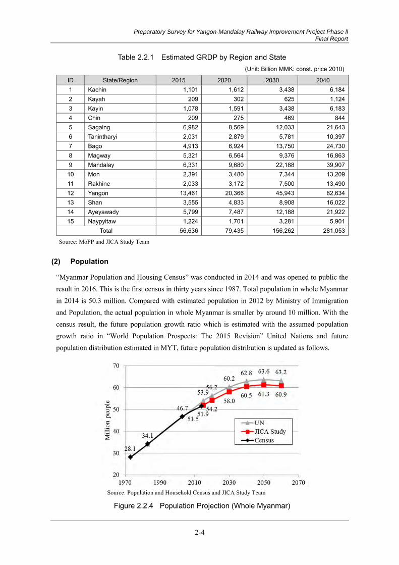
Preparatory Survey for Yangon-Mandalay Railway Improvement Project Phase ll Final Report
2-4
Table 2.2.1 Estimated GRDP by Region and State (Unit: Billion MMK: const. price 2010)
ID State/Region 2015 2020 2030 2040 1 Kachin 1,101 1,612 3,438 6,1842 Kayah 209 302 625 1,1243 Kayin 1,078 1,591 3,438 6,1834 Chin 209 275 469 8445 Sagaing 6,982 8,569 12,033 21,6436 Tanintharyi 2,031 2,879 5,781 10,3977 Bago 4,913 6,924 13,750 24,7308 Magway 5,321 6,564 9,376 16,8639 Mandalay 6,331 9,680 22,188 39,907
10 Mon 2,391 3,480 7,344 13,20911 Rakhine 2,033 3,172 7,500 13,49012 Yangon 13,461 20,366 45,943 82,63413 Shan 3,555 4,833 8,908 16,02214 Ayeyawady 5,799 7,487 12,188 21,92215 Naypyitaw 1,224 1,701 3,281 5,901
Total 56,636 79,435 156,262 281,053
Source: MoFP and JICA Study Team
Population (2)
“Myanmar Population and Housing Census” was conducted in 2014 and was opened to public the result in 2016. This is the first census in thirty years since 1987. Total population in whole Myanmar in 2014 is 50.3 million. Compared with estimated population in 2012 by Ministry of Immigration and Population, the actual population in whole Myanmar is smaller by around 10 million. With the census result, the future population growth ratio which is estimated with the assumed population growth ratio in “World Population Prospects: The 2015 Revision” United Nations and future population distribution estimated in MYT, future population distribution is updated as follows.
Source: Population and Household Census and JICA Study Team
Figure 2.2.4 Population Projection (Whole Myanmar)
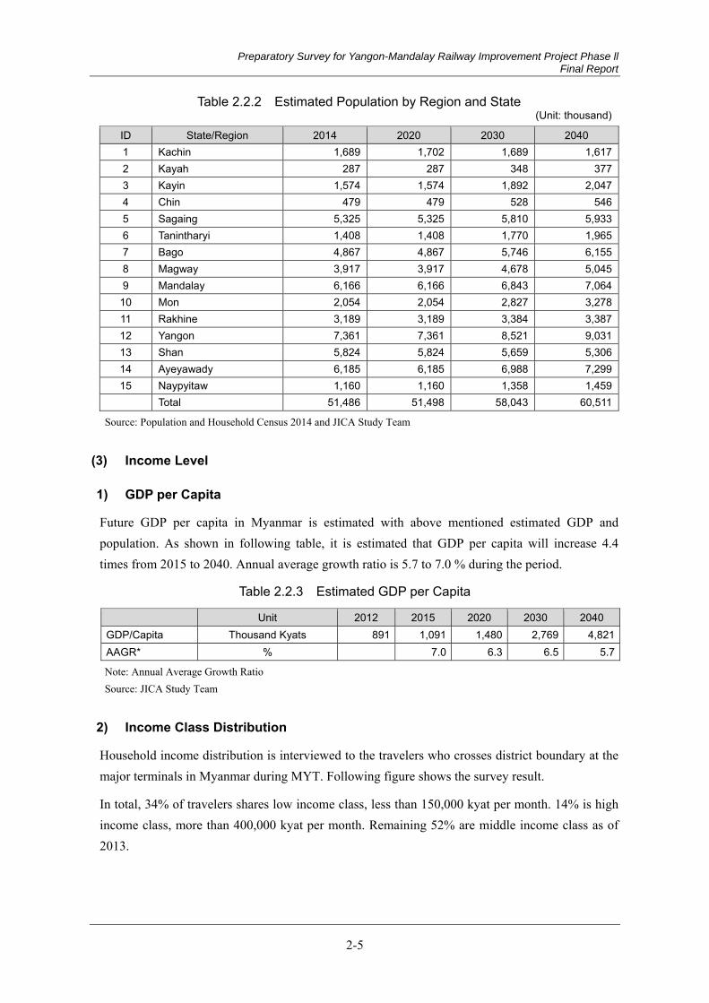
Preparatory Survey for Yangon-Mandalay Railway Improvement Project Phase ll Final Report
2-5
Table 2.2.2 Estimated Population by Region and State (Unit: thousand)
ID State/Region 2014 2020 2030 2040 1 Kachin 1,689 1,702 1,689 1,6172 Kayah 287 287 348 3773 Kayin 1,574 1,574 1,892 2,0474 Chin 479 479 528 5465 Sagaing 5,325 5,325 5,810 5,9336 Tanintharyi 1,408 1,408 1,770 1,9657 Bago 4,867 4,867 5,746 6,1558 Magway 3,917 3,917 4,678 5,0459 Mandalay 6,166 6,166 6,843 7,064
10 Mon 2,054 2,054 2,827 3,27811 Rakhine 3,189 3,189 3,384 3,38712 Yangon 7,361 7,361 8,521 9,03113 Shan 5,824 5,824 5,659 5,30614 Ayeyawady 6,185 6,185 6,988 7,29915 Naypyitaw 1,160 1,160 1,358 1,459
Total 51,486 51,498 58,043 60,511
Source: Population and Household Census 2014 and JICA Study Team
Income Level (3)
1) GDP per Capita
Future GDP per capita in Myanmar is estimated with above mentioned estimated GDP and population. As shown in following table, it is estimated that GDP per capita will increase 4.4 times from 2015 to 2040. Annual average growth ratio is 5.7 to 7.0 % during the period.
Table 2.2.3 Estimated GDP per Capita
Unit 2012 2015 2020 2030 2040 GDP/Capita Thousand Kyats 891 1,091 1,480 2,769 4,821AAGR* % 7.0 6.3 6.5 5.7
Note: Annual Average Growth Ratio Source: JICA Study Team
2) Income Class Distribution
Household income distribution is interviewed to the travelers who crosses district boundary at the major terminals in Myanmar during MYT. Following figure shows the survey result.
In total, 34% of travelers shares low income class, less than 150,000 kyat per month. 14% is high income class, more than 400,000 kyat per month. Remaining 52% are middle income class as of 2013.
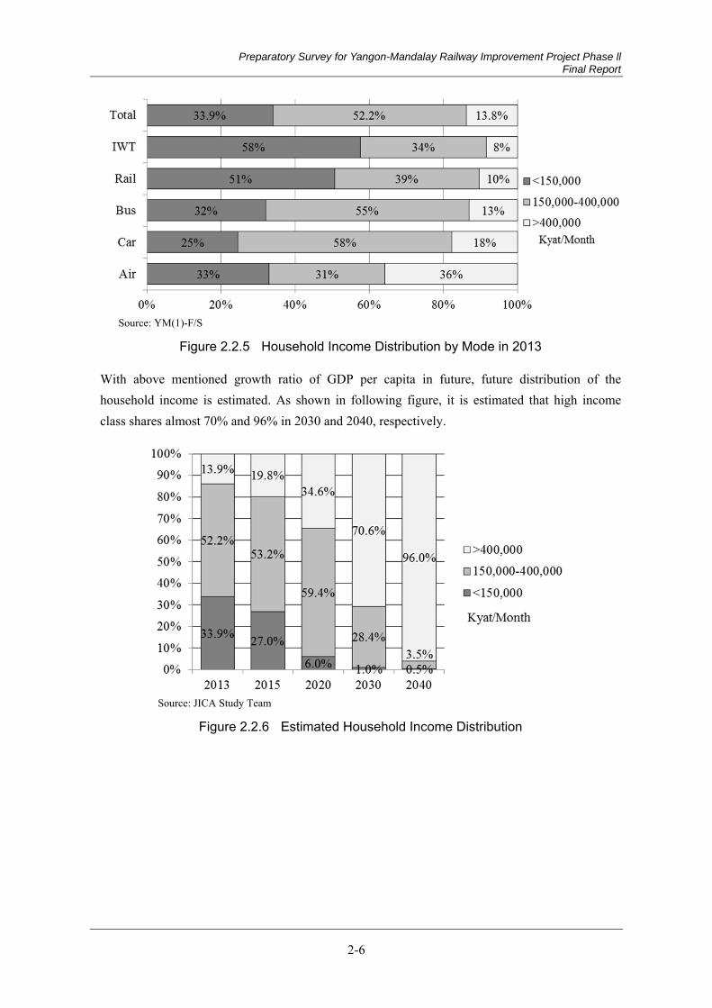
Preparatory Survey for Yangon-Mandalay Railway Improvement Project Phase ll Final Report
2-6
Source: YM(1)-F/S
Figure 2.2.5 Household Income Distribution by Mode in 2013
With above mentioned growth ratio of GDP per capita in future, future distribution of the household income is estimated. As shown in following figure, it is estimated that high income class shares almost 70% and 96% in 2030 and 2040, respectively.
Source: JICA Study Team
Figure 2.2.6 Estimated Household Income Distribution
Preparatory Survey for Yangon-Mandalay Railway Improvement Project Phase ll Final Report
2-7
Update of Transportation Network 2.2.3
Future Transportation Network (1)
In MYT, future transportation development plan was established by 2030 as shown in following figure. In this study, the future transportation is assumed as the plans in MYT. Following plan is the key assumption for forecasting the demand for Yangon-Mandalay railway.
Yangon - Mandalay Expressway opens for truck by 2023.
Yangon Inner & Outer Ring Road open by 2030.
Dry ports open at Ywarthargyi and Myitnge by 2023.
Additionally, it is assumed that fuel transportation shall be started by railway between Yangon and Mandalay based on the interview with MR.
Fare System for Yangon-Mandalay railway (2)
1) Passenger
In YM(1)-F/S, three alternatives are studied for passenger fare system which is distance proportional system , namely 15 kyat/km, 30 kyat/km and 45 kyat/km. As a result, it is estimated that total fare-box revenue is maximize in 30kyat/km case and decided as 30 kyat/km.
2) Cargo
As of now, cargo train is charged 26.3 kyat/km and 39.4 kyat/km for general cargo and fuel cargo, respectively. In this study it is assumed same fare system is applied based on the discussion with MR.

Preparatory Survey for Yangon-Mandalay Railway Improvement Project Phase ll Final Report
2-8
Source: JICA Study Team
Figure 2.2.7 Assumed Future Transportation Network along Yangon – Mandalay Railway
Update of Passenger Demand Forecast 2.2.4
Trip Generation (1)
Population growth, economic development and improvement of income level affect the trip generation volume. In the MYT, considering examples of economic development and traffic growth in neighboring countries, the GDP elasticity of trip generation from each zone from 2013 to 2015 and from 2015 to 2030 were defined as 1.0 and 1.2, respectively. Total daily trip generation in 2013 is approximately 300 thousand. Daily trip generation in 2040 is estimated 2.4 million.

Preparatory Survey for Yangon-Mandalay Railway Improvement Project Phase ll Final Report
2-9
Source: JICA Study Team
Figure 2.2.8 Estimated Future Trip Generation in Myanmar
Source: JICA Study Team
Figure 2.2.9 Estimated Future Trip Generation by State/Region
0
1,000
2,000
3,000
4,000
5,000
6,000
0
50
100
150
200
250
300
2015 2020 2030 2040
GD
P (T
rillio
n M
MK
)
Trip
gen
erat
ion
(mil.
trip
s/da
y)
GDP (Right axis:Trillion MMK)
Trip (Left axis: mil.trips/day)
23.8
2.4
13.9
0.2
43.3
7.2
122.6
43.3
367.0
49.5
17.8
424.9
44.3
58.5
131.6
12.2
1.2
6.0
0.1
31.2
4.4
67.1
29.6
168.8
26.5
8.5
214.0
24.5
37.9
76.1
5.9
0.6
2.6
0.1
21.5
2.4
34.7
20.1
74.6
13.0
3.7
99.9
13.3
23.4
40.7
0.0 50.0 100.0 150.0 200.0 250.0 300.0 350.0 400.0 450.0
Kachin
Kayah
Kayin
Chin
Sagaing
Tanintharyi
Bago
Magway
Mandalay
Mon
Rakhine
Yangon
Shan
Ayeyarwady
Nay Pyi Taw
thousand trips / day
201520202030
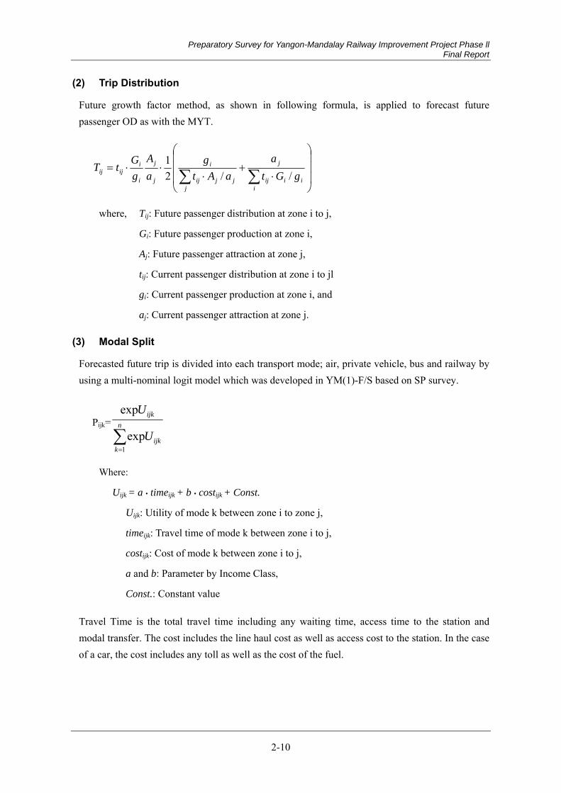
Preparatory Survey for Yangon-Mandalay Railway Improvement Project Phase ll Final Report
2-10
Trip Distribution (2)
Future growth factor method, as shown in following formula, is applied to forecast future passenger OD as with the MYT.
i
iiij
j
jjjij
i
j
j
i
iijij gGt
aaAt
gaA
gGtT
//21
where, Tij: Future passenger distribution at zone i to j,
Gi: Future passenger production at zone i,
Aj: Future passenger attraction at zone j,
tij: Current passenger distribution at zone i to jl
gi: Current passenger production at zone i, and
aj: Current passenger attraction at zone j.
Modal Split (3)
Forecasted future trip is divided into each transport mode; air, private vehicle, bus and railway by using a multi-nominal logit model which was developed in YM(1)-F/S based on SP survey.
Pijk=
n
kijk
ijk
U
U
1exp
exp
Where:
Uijk = a • timeijk + b • costijk + Const.
Uijk: Utility of mode k between zone i to zone j,
timeijk: Travel time of mode k between zone i to j,
costijk: Cost of mode k between zone i to j,
a and b: Parameter by Income Class,
Const.: Constant value
Travel Time is the total travel time including any waiting time, access time to the station and modal transfer. The cost includes the line haul cost as well as access cost to the station. In the case of a car, the cost includes any toll as well as the cost of the fuel.
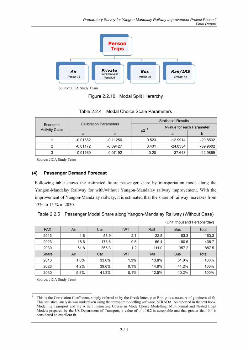
Preparatory Survey for Yangon-Mandalay Railway Improvement Project Phase ll Final Report
2-11
Source: JICA Study Team
Figure 2.2.10 Modal Split Hierarchy
Table 2.2.4 Modal Choice Scale Parameters
Economic Activity Class
Calibration Parameters Statistical Results
ρ2 1 t-value for each Parameter
a b a b 1 -0.01382 -0.11256 0.523 -12.9914 -20.85322 -0.01172 -0.09427 0.431 -24.8334 -39.96023 -0.01169 -0.07192 0.20 -37.643 -42.9869
Source: JICA Study Team
Passenger Demand Forecast (4)
Following table shows the estimated future passenger share by transportation mode along the Yangon-Mandalay Railway for with/without Yangon-Mandalay railway improvement. With the improvement of Yangon-Mandalay railway, it is estimated that the share of railway increases from 13% to 15 % in 2030.
Table 2.2.5 Passenger Modal Share along Yangon-Mandalay Railway (Without Case) (Unit: thousand Persons/day)
PAX Air Car IWT Rail Bus Total 2013 1.6 53.9 2.1 22.5 83.3 163.32023 18.6 173.6 0.6 65.4 180.6 438.72030 51.8 366.3 1.2 111.0 357.2 887.5Share Air Car IWT Rail Bus Total 2013 1.0% 33.0% 1.3% 13.8% 51.0% 100%2023 4.2% 39.6% 0.1% 14.9% 41.2% 100%2030 5.8% 41.3% 0.1% 12.5% 40.2% 100%
Source: JICA Study Team
1 This is the Correlation Coefficient, simply referred to by the Greek letter, ρ or Rho. ρ is a measure of goodness of fit.
This statistical analysis was undertaken using the transport modelling software, STRADA. As reported in the text book, Modelling Transport and the A Self Instructing Course in Mode Choice Modelling: Multinomial and Nested Logit Models prepared by the US Department of Transport, a value of ρ2 of 0.2 is acceptable and that greater than 0.4 is considered an excellent fit.

Preparatory Survey for Yangon-Mandalay Railway Improvement Project Phase ll Final Report
2-12
Table 2.2.6 Passenger Modal Share along Yangon-Mandalay Railway (With Case) (Unit: thousand Persons/day)
PAX Air Car IWT Rail Bus Total 2023 17.2 169.2 0.7 80.7 171.0 438.72030 49.5 357.7 1.3 132.4 346.6 887.5Share Air Car IWT Rail Bus Total 2023 3.9% 38.6% 0.2% 18.4% 39.0% 100%2030 5.6% 40.3% 0.1% 14.9% 39.1% 100%
Source: JICA Study Team
Passenger Demand Forecast for Yangon-Mandalay Railway Line (5)
Based on the above mentioned passenger demand forecast model, sectional passenger volume was estimated. It is estimate that total passenger volume in Yangon-Mandalay railway in 2023 and 2030 is 80,700 and 132,400 person per day, respectively. Maximum sectional traffic volume in 2030 is 78,600 passengers per both-ways per day between Ywadaw - Naypyitaw section.
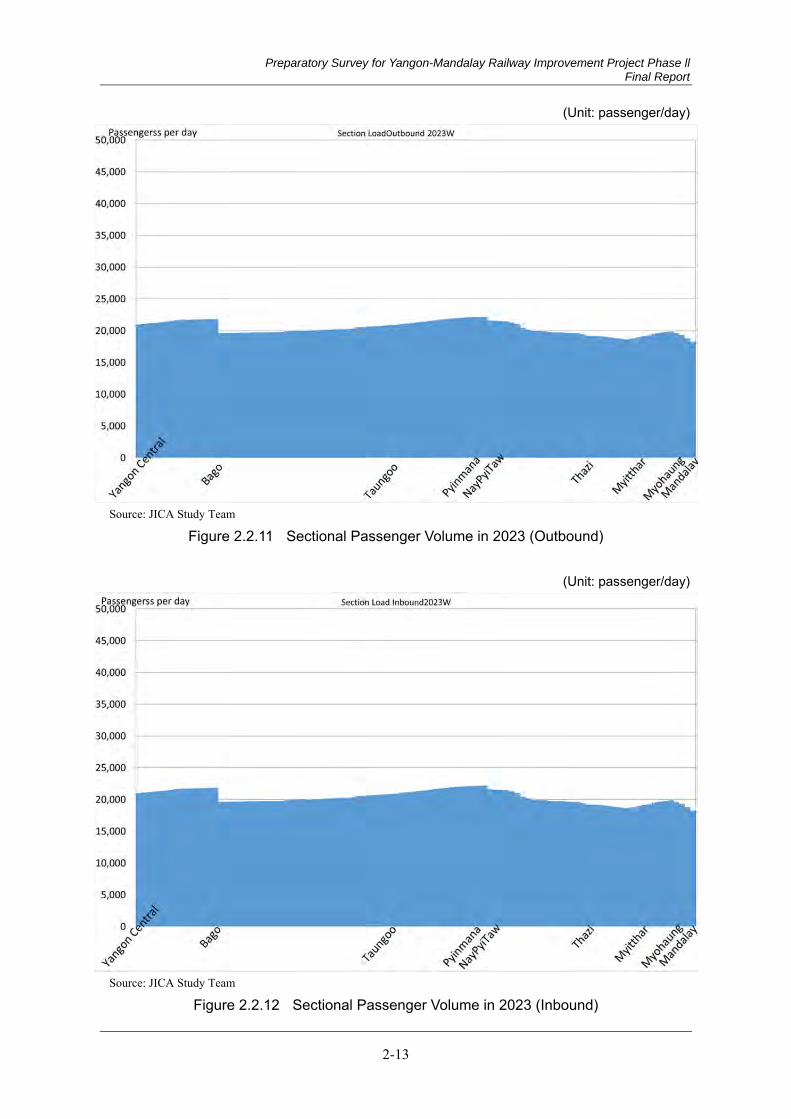
Preparatory Survey for Yangon-Mandalay Railway Improvement Project Phase ll Final Report
2-13
(Unit: passenger/day)
Source: JICA Study Team
Figure 2.2.11 Sectional Passenger Volume in 2023 (Outbound)
(Unit: passenger/day)
Source: JICA Study Team
Figure 2.2.12 Sectional Passenger Volume in 2023 (Inbound)
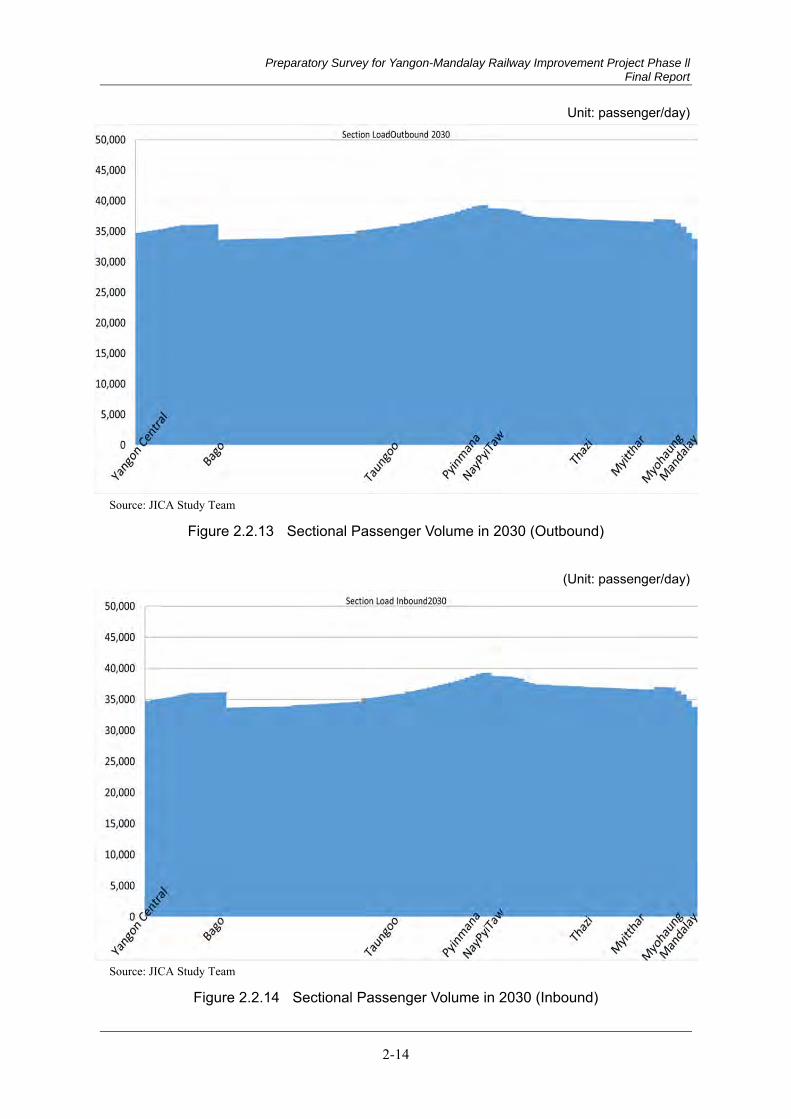
Preparatory Survey for Yangon-Mandalay Railway Improvement Project Phase ll Final Report
2-14
Unit: passenger/day)
Source: JICA Study Team
Figure 2.2.13 Sectional Passenger Volume in 2030 (Outbound)
(Unit: passenger/day)
Source: JICA Study Team
Figure 2.2.14 Sectional Passenger Volume in 2030 (Inbound)
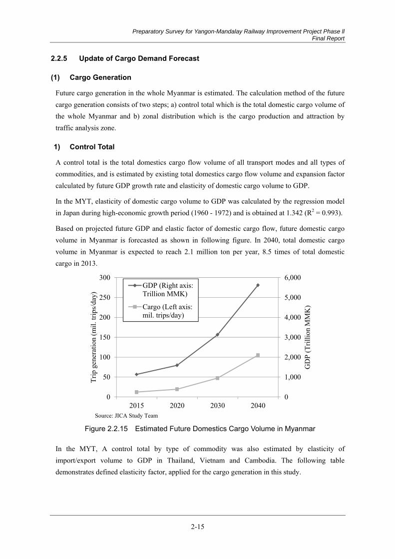
Preparatory Survey for Yangon-Mandalay Railway Improvement Project Phase ll Final Report
2-15
Update of Cargo Demand Forecast 2.2.5
Cargo Generation (1)
Future cargo generation in the whole Myanmar is estimated. The calculation method of the future cargo generation consists of two steps; a) control total which is the total domestic cargo volume of the whole Myanmar and b) zonal distribution which is the cargo production and attraction by traffic analysis zone.
1) Control Total
A control total is the total domestics cargo flow volume of all transport modes and all types of commodities, and is estimated by existing total domestics cargo flow volume and expansion factor calculated by future GDP growth rate and elasticity of domestic cargo volume to GDP.
In the MYT, elasticity of domestic cargo volume to GDP was calculated by the regression model in Japan during high-economic growth period (1960 - 1972) and is obtained at 1.342 (R2 = 0.993).
Based on projected future GDP and elastic factor of domestic cargo flow, future domestic cargo volume in Myanmar is forecasted as shown in following figure. In 2040, total domestic cargo volume in Myanmar is expected to reach 2.1 million ton per year, 8.5 times of total domestic cargo in 2013.
Source: JICA Study Team
Figure 2.2.15 Estimated Future Domestics Cargo Volume in Myanmar
In the MYT, A control total by type of commodity was also estimated by elasticity of import/export volume to GDP in Thailand, Vietnam and Cambodia. The following table demonstrates defined elasticity factor, applied for the cargo generation in this study.
0
1,000
2,000
3,000
4,000
5,000
6,000
0
50
100
150
200
250
300
2015 2020 2030 2040
GD
P (T
rillio
n M
MK
)
Trip
gen
erat
ion
(mil.
trip
s/da
y)
GDP (Right axis:Trillion MMK)
Cargo (Left axis:mil. trips/day)
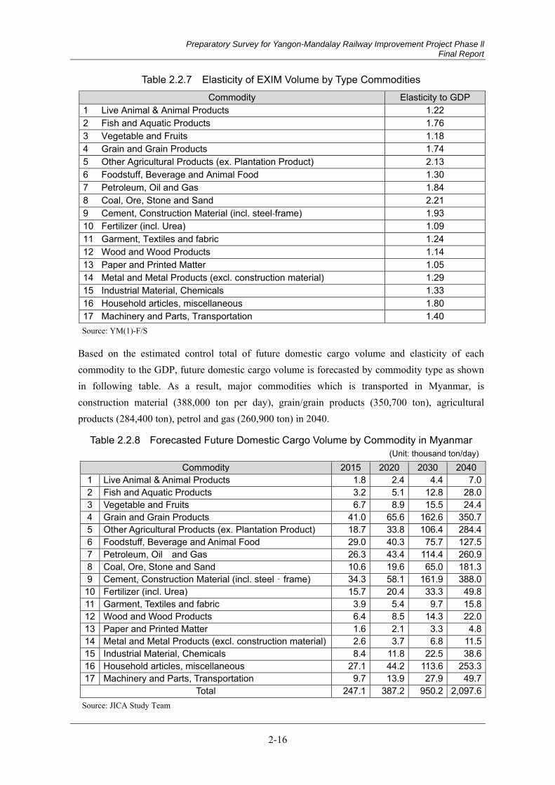
Preparatory Survey for Yangon-Mandalay Railway Improvement Project Phase ll Final Report
2-16
Table 2.2.7 Elasticity of EXIM Volume by Type Commodities Commodity Elasticity to GDP
1 Live Animal & Animal Products 1.22 2 Fish and Aquatic Products 1.76 3 Vegetable and Fruits 1.18 4 Grain and Grain Products 1.74 5 Other Agricultural Products (ex. Plantation Product) 2.13 6 Foodstuff, Beverage and Animal Food 1.30 7 Petroleum, Oil and Gas 1.84 8 Coal, Ore, Stone and Sand 2.21 9 Cement, Construction Material (incl. steel-frame) 1.93 10 Fertilizer (incl. Urea) 1.09 11 Garment, Textiles and fabric 1.24 12 Wood and Wood Products 1.14 13 Paper and Printed Matter 1.05 14 Metal and Metal Products (excl. construction material) 1.29 15 Industrial Material, Chemicals 1.33 16 Household articles, miscellaneous 1.80 17 Machinery and Parts, Transportation 1.40 Source: YM(1)-F/S
Based on the estimated control total of future domestic cargo volume and elasticity of each commodity to the GDP, future domestic cargo volume is forecasted by commodity type as shown in following table. As a result, major commodities which is transported in Myanmar, is construction material (388,000 ton per day), grain/grain products (350,700 ton), agricultural products (284,400 ton), petrol and gas (260,900 ton) in 2040.
Table 2.2.8 Forecasted Future Domestic Cargo Volume by Commodity in Myanmar (Unit: thousand ton/day)
Commodity 2015 2020 2030 20401 Live Animal & Animal Products 1.8 2.4 4.4 7.02 Fish and Aquatic Products 3.2 5.1 12.8 28.03 Vegetable and Fruits 6.7 8.9 15.5 24.44 Grain and Grain Products 41.0 65.6 162.6 350.75 Other Agricultural Products (ex. Plantation Product) 18.7 33.8 106.4 284.46 Foodstuff, Beverage and Animal Food 29.0 40.3 75.7 127.57 Petroleum, Oil and Gas 26.3 43.4 114.4 260.98 Coal, Ore, Stone and Sand 10.6 19.6 65.0 181.39 Cement, Construction Material (incl. steel‐frame) 34.3 58.1 161.9 388.010 Fertilizer (incl. Urea) 15.7 20.4 33.3 49.811 Garment, Textiles and fabric 3.9 5.4 9.7 15.812 Wood and Wood Products 6.4 8.5 14.3 22.013 Paper and Printed Matter 1.6 2.1 3.3 4.814 Metal and Metal Products (excl. construction material) 2.6 3.7 6.8 11.515 Industrial Material, Chemicals 8.4 11.8 22.5 38.616 Household articles, miscellaneous 27.1 44.2 113.6 253.317 Machinery and Parts, Transportation 9.7 13.9 27.9 49.7
Total 247.1 387.2 950.2 2,097.6Source: JICA Study Team
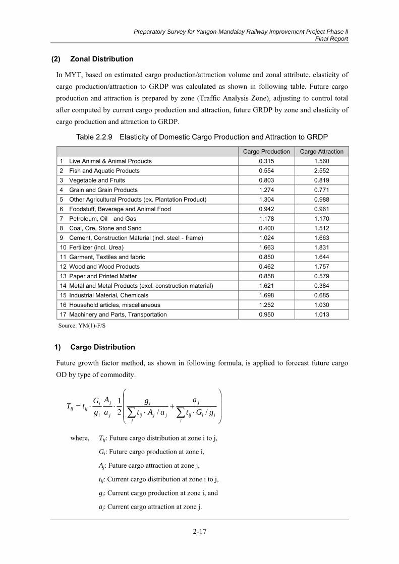
Preparatory Survey for Yangon-Mandalay Railway Improvement Project Phase ll Final Report
2-17
Zonal Distribution (2)
In MYT, based on estimated cargo production/attraction volume and zonal attribute, elasticity of cargo production/attraction to GRDP was calculated as shown in following table. Future cargo production and attraction is prepared by zone (Traffic Analysis Zone), adjusting to control total after computed by current cargo production and attraction, future GRDP by zone and elasticity of cargo production and attraction to GRDP.
Table 2.2.9 Elasticity of Domestic Cargo Production and Attraction to GRDP
Cargo Production Cargo Attraction1 Live Animal & Animal Products 0.315 1.560 2 Fish and Aquatic Products 0.554 2.552 3 Vegetable and Fruits 0.803 0.819 4 Grain and Grain Products 1.274 0.771 5 Other Agricultural Products (ex. Plantation Product) 1.304 0.988 6 Foodstuff, Beverage and Animal Food 0.942 0.961 7 Petroleum, Oil and Gas 1.178 1.170 8 Coal, Ore, Stone and Sand 0.400 1.512 9 Cement, Construction Material (incl. steel‐frame) 1.024 1.663 10 Fertilizer (incl. Urea) 1.663 1.831 11 Garment, Textiles and fabric 0.850 1.644 12 Wood and Wood Products 0.462 1.757 13 Paper and Printed Matter 0.858 0.579 14 Metal and Metal Products (excl. construction material) 1.621 0.384 15 Industrial Material, Chemicals 1.698 0.685 16 Household articles, miscellaneous 1.252 1.030 17 Machinery and Parts, Transportation 0.950 1.013
Source: YM(1)-F/S
1) Cargo Distribution
Future growth factor method, as shown in following formula, is applied to forecast future cargo OD by type of commodity.
i
iiij
j
jjjij
i
j
j
i
iijij gGt
aaAt
gaA
gGtT
//21
where, Tij: Future cargo distribution at zone i to j,
Gi: Future cargo production at zone i,
Aj: Future cargo attraction at zone j,
tij: Current cargo distribution at zone i to j,
gi: Current cargo production at zone i, and
aj: Current cargo attraction at zone j.

Preparatory Survey for Yangon-Mandalay Railway Improvement Project Phase ll Final Report
2-18
Modal Split (3)
Forecasted future cargo by type of commodity is divided into each transport mode; costal, inland water transport, railway and truck by using a logit model.
)exp()exp()exp(
jUiUiU
iP
where, Ui = a • timei + b • costi + Intercept
Uj = a • timej + b • costj
Ui: Utility of mode i,
timei: Travel time of mode i,
costi: Cost of mode i,
Uj: Utility of mode j,
timej: Travel time of mode j, and
costj: Cost of mode j.
In the MYT, modal split model is developed by the three steps by type of commodity, applying the binary choice model, (i) coastal shipping - inland transport, (ii) inland waterways and land transport, and (iii) railway and truck.
Source: YM(1)-F/S
Figure 2.2.16 Binary Choice Type Modal Split Model
Following tables show estimated parameters for modal split model computed by current cargo OD by commodity and transport mode.
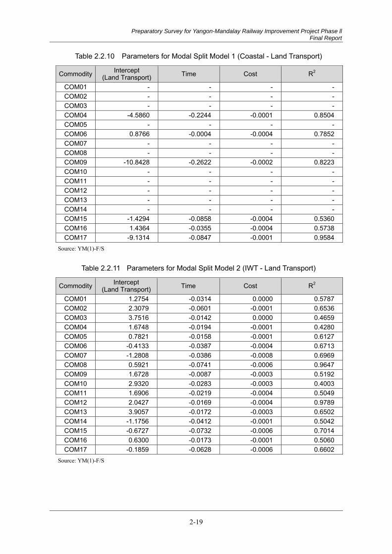
Preparatory Survey for Yangon-Mandalay Railway Improvement Project Phase ll Final Report
2-19
Table 2.2.10 Parameters for Modal Split Model 1 (Coastal - Land Transport)
Commodity Intercept (Land Transport) Time Cost R2
COM01 - - - -COM02 - - - -COM03 - - - -COM04 -4.5860 -0.2244 -0.0001 0.8504COM05 - - - -COM06 0.8766 -0.0004 -0.0004 0.7852COM07 - - - -COM08 - - - -COM09 -10.8428 -0.2622 -0.0002 0.8223COM10 - - - -COM11 - - - -COM12 - - - -COM13 - - - -COM14 - - - -COM15 -1.4294 -0.0858 -0.0004 0.5360COM16 1.4364 -0.0355 -0.0004 0.5738COM17 -9.1314 -0.0847 -0.0001 0.9584
Source: YM(1)-F/S
Table 2.2.11 Parameters for Modal Split Model 2 (IWT - Land Transport)
Commodity Intercept (Land Transport) Time Cost R2
COM01 1.2754 -0.0314 0.0000 0.5787COM02 2.3079 -0.0601 -0.0001 0.6536COM03 3.7516 -0.0142 0.0000 0.4659COM04 1.6748 -0.0194 -0.0001 0.4280COM05 0.7821 -0.0158 -0.0001 0.6127COM06 -0.4133 -0.0387 -0.0004 0.6713COM07 -1.2808 -0.0386 -0.0008 0.6969COM08 0.5921 -0.0741 -0.0006 0.9647COM09 1.6728 -0.0087 -0.0003 0.5192COM10 2.9320 -0.0283 -0.0003 0.4003COM11 1.6906 -0.0219 -0.0004 0.5049COM12 2.0427 -0.0169 -0.0004 0.9789COM13 3.9057 -0.0172 -0.0003 0.6502COM14 -1.1756 -0.0412 -0.0001 0.5042COM15 -0.6727 -0.0732 -0.0006 0.7014COM16 0.6300 -0.0173 -0.0001 0.5060COM17 -0.1859 -0.0628 -0.0006 0.6602
Source: YM(1)-F/S
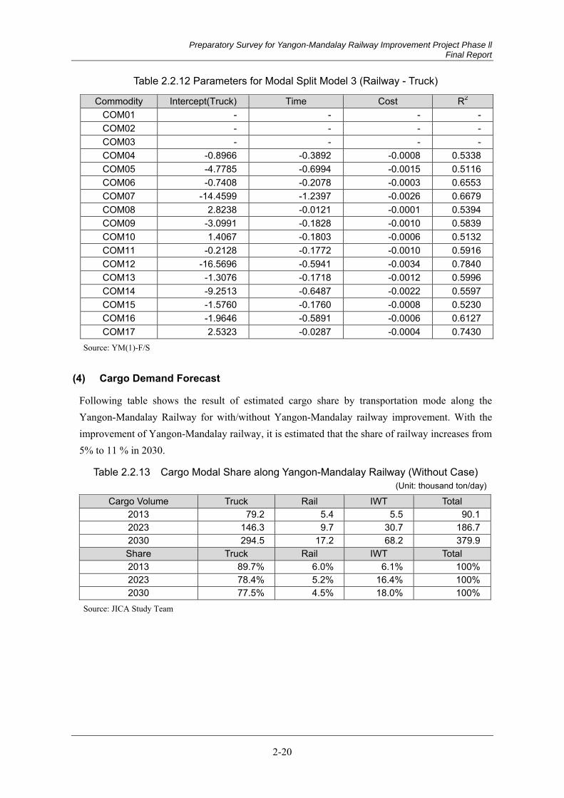
Preparatory Survey for Yangon-Mandalay Railway Improvement Project Phase ll Final Report
2-20
Table 2.2.12 Parameters for Modal Split Model 3 (Railway - Truck)
Commodity Intercept(Truck) Time Cost R2
COM01 - - - -COM02 - - - -COM03 - - - -COM04 -0.8966 -0.3892 -0.0008 0.5338COM05 -4.7785 -0.6994 -0.0015 0.5116COM06 -0.7408 -0.2078 -0.0003 0.6553COM07 -14.4599 -1.2397 -0.0026 0.6679COM08 2.8238 -0.0121 -0.0001 0.5394COM09 -3.0991 -0.1828 -0.0010 0.5839COM10 1.4067 -0.1803 -0.0006 0.5132COM11 -0.2128 -0.1772 -0.0010 0.5916COM12 -16.5696 -0.5941 -0.0034 0.7840COM13 -1.3076 -0.1718 -0.0012 0.5996COM14 -9.2513 -0.6487 -0.0022 0.5597COM15 -1.5760 -0.1760 -0.0008 0.5230COM16 -1.9646 -0.5891 -0.0006 0.6127COM17 2.5323 -0.0287 -0.0004 0.7430
Source: YM(1)-F/S
Cargo Demand Forecast (4)
Following table shows the result of estimated cargo share by transportation mode along the Yangon-Mandalay Railway for with/without Yangon-Mandalay railway improvement. With the improvement of Yangon-Mandalay railway, it is estimated that the share of railway increases from 5% to 11 % in 2030.
Table 2.2.13 Cargo Modal Share along Yangon-Mandalay Railway (Without Case) (Unit: thousand ton/day)
Cargo Volume Truck Rail IWT Total 2013 79.2 5.4 5.5 90.12023 146.3 9.7 30.7 186.72030 294.5 17.2 68.2 379.9Share Truck Rail IWT Total 2013 89.7% 6.0% 6.1% 100%2023 78.4% 5.2% 16.4% 100%2030 77.5% 4.5% 18.0% 100%
Source: JICA Study Team

Preparatory Survey for Yangon-Mandalay Railway Improvement Project Phase ll Final Report
2-21
Table 2.2.14 Cargo Modal Share along Yangon-Mandalay Railway (With Case) (Unit: thousand ton/day)
Cargo Volume Truck Rail IWT Total 2023 135.1 20.9 30.7 186.72030 271.5 40.7 67.7 379.9Share Truck Rail IWT Total 2023 72.4% 11.2% 16.4% 100%2030 71.5% 10.7% 17.8% 100%
Source: JICA Study Team
Cargo Demand Forecast for Yangon-Mandalay Railway Line (5)
Based on the above mentioned freight demand forecast model, station to station cargo volume was estimated as follows. In the assignment process, it is assumed that bulk cargo and general cargo will be handled at Myohaung station and Myinge area in Mandalay area, respectively.
It is estimate that total cargo volume in Yangon-Mandalay railway in 2025 and 2030 is 30,000 and 41,000 ton per day, respectively.
Table 2.2.15 Station to Station Cargo Volume in 2025 (Outbound) (Unit: ton/day)
Commodity Yangon
TotalMyohaung Myinge Thazi Pyinmana Taungoo
1 Live Animal & Animal Products 0 0 0 0 0 02 Fish and Aquatic Products 0 0 0 0 0 03 Vegetable and Fruits 0 0 0 0 0 04 Grain and Grain Products 153 0 2 0 1 157
5 Other Agricultural Products (ex. Plantation Product) 0 199 0 1 1 201
6 Foodstuff, Beverage and Animal Food 0 1,068 137 93 23 1,321
7 Petroleum, Oil and Gas 5,177 0 0 0 0 5,1778 Coal, Ore, Stone and Sand 18 0 3 6 0 26
9 Cement, Construction Material (incl. steel‐frame) 5,672 0 186 21 65 5,944
10 Fertilizer (incl. Urea) 0 43 0 0 0 4311 Garment, Textiles and fabric 0 54 0 0 0 5412 Wood and Wood Products 0 120 0 0 0 12013 Paper and Printed Matter 0 137 0 0 0 138
14 Metal and Metal Products (excl. construction material) 435 0 2 0 0 437
15 Industrial Material, Chemicals 0 866 28 34 4 93116 Household articles, miscellaneous 0 142 2 4 3 15117 Machinery and Parts, Transportation 0 80 1 6 1 88
Total 11,455 2,708 360 167 99 14,788
Source: JICA Study Team
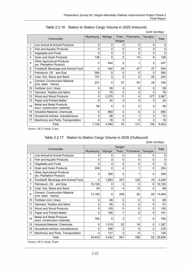
Preparatory Survey for Yangon-Mandalay Railway Improvement Project Phase ll Final Report
2-22
Table 2.2.16 Station to Station Cargo Volume in 2025 (Inbound) (Unit: ton/day)
Commodity Myohaung Myinge Thazi Pyinmana Taungoo
TotalYangon
1 Live Animal & Animal Products 0 0 0 0 0 02 Fish and Aquatic Products 0 0 0 0 0 03 Vegetable and Fruits 0 0 0 0 0 04 Grain and Grain Products 138 0 2 10 8 158
5 Other Agricultural Products (ex. Plantation Product) 0 444 0 1 2 447
6 Foodstuff, Beverage and Animal Food 0 442 24 47 27 5407 Petroleum, Oil and Gas 564 0 0 0 0 5648 Coal, Ore, Stone and Sand 151 0 0 9 83 244
9 Cement, Construction Material (incl. steel‐frame) 231 0 27 54 24 336
10 Fertilizer (incl. Urea) 0 59 0 0 0 5911 Garment, Textiles and fabric 0 75 2 0 0 7612 Wood and Wood Products 0 2,375 11 4 577 2,96713 Paper and Printed Matter 0 24 0 0 0 24
14 Metal and Metal Products (excl. construction material) 58 0 0 0 0 58
15 Industrial Material, Chemicals 0 880 3 5 2 89016 Household articles, miscellaneous 0 68 0 1 3 7217 Machinery and Parts, Transportation 0 18 0 0 0 18
Total 1,142 4,384 70 131 726 6,452Source: JICA Study Team
Table 2.2.17 Station to Station Cargo Volume in 2030 (Outbound) (Unit: ton/day)
Commodity Yangon
TotalMyohaung Myinge Thazi Pyinmana Taungoo
1 Live Animal & Animal Products 0 0 0 0 0 02 Fish and Aquatic Products 0 0 0 0 0 03 Vegetable and Fruits 0 0 0 0 0 04 Grain and Grain Products 249 0 4 1 0 254
5 Other Agricultural Products (ex. Plantation Product) 0 358 0 1 0 359
6 Foodstuff, Beverage and Animal Food 0 1,863 247 120 19 2,2497 Petroleum, Oil and Gas 10,183 0 0 0 0 10,1838 Coal, Ore, Stone and Sand 54 0 4 12 0 69
9 Cement, Construction Material (incl. steel‐frame) 13,183 0 246 26 29 13,484
10 Fertilizer (incl. Urea) 0 68 0 0 0 6811 Garment, Textiles and fabric 0 90 0 0 0 9112 Wood and Wood Products 0 155 0 0 0 15513 Paper and Printed Matter 0 180 1 0 0 181
14 Metal and Metal Products (excl. construction material) 765 0 3 1 0 768
15 Industrial Material, Chemicals 0 1,319 52 16 0 1,38716 Household articles, miscellaneous 0 268 2 5 2 27817 Machinery and Parts, Transportation 0 121 2 6 1 129
Total 24,433 4,422 561 188 52 29,656Source: JICA Study Team
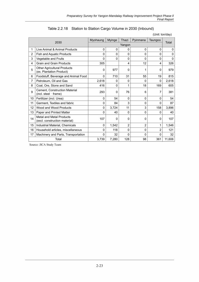
Preparatory Survey for Yangon-Mandalay Railway Improvement Project Phase ll Final Report
2-23
Table 2.2.18 Station to Station Cargo Volume in 2030 (Inbound) (Unit: ton/day)
2030 Myohaung Myinge Thazi Pyinmana Taungoo
TotalYangon
1 Live Animal & Animal Products 0 0 0 0 0 02 Fish and Aquatic Products 0 0 0 0 0 03 Vegetable and Fruits 0 0 0 0 0 04 Grain and Grain Products 305 4 12 4 326
5 Other Agricultural Products (ex. Plantation Product) 0 977 0 1 0 979
6 Foodstuff, Beverage and Animal Food 0 710 31 55 19 8157 Petroleum, Oil and Gas 2,618 0 0 0 0 2,6188 Coal, Ore, Stone and Sand 416 0 1 18 169 605
9 Cement, Construction Material (incl. steel‐frame) 293 0 76 6 7 381
10 Fertilizer (incl. Urea) 0 54 0 0 0 5411 Garment, Textiles and fabric 0 84 3 0 0 8712 Wood and Wood Products 0 3,724 11 3 158 3,89613 Paper and Printed Matter 0 40 0 0 0 40
14 Metal and Metal Products (excl. construction material) 107 0 0 0 0 107
15 Industrial Material, Chemicals 0 1,542 2 2 1 1,54616 Household articles, miscellaneous 0 118 0 0 2 12117 Machinery and Parts, Transportation 0 32 0 0 0 32
Total 3,739 7,280 128 98 361 11,606
Source: JICA Study Team
Preparatory Survey for Yangon-Mandalay Railway Improvement Project Phase ll Final Report
3-1
Chapter 3 Natural Condition
3.1 Introduction
Below natural condition surveys for implementing a project for the improvement of the existing railway (Taungoo station to Mandalay station: approximately 350km) were conducted in this study.
(a) Climate
Meteorological Data and Hydrological Data Collection
Hydrological Survey
(b) Earthquake
(c) Geotechnical Conditions
The result of these natural condition surveys are described for reference of evaluation of study by each experts of JST , examination of additional surevey in next detailed desing stage and reference of design conditons in next detailed design stage.
3.2 Climate
Objective 3.2.1
The objective of the survey is to collect basic meteorological and hydrological information. The situation regarding the flooding occurred in the past around three locations selected by the Myanmar Railway Authority along the Taungoo-Mandalay Railway Track was collected from MR staffs or local resident peoples.
Meteorological Data and Hydrological Data Collection (1)
Meteorological data was collected from seven Meteorology and Hydrology stations along the Taungoo-Mandalay railway. These stations are Taungoo, Yamethin, Pyinmana, Tatkone, Meikhtila, Kyaukse and Mandalay.The Hydrological Data (Water Level) was collected from three major rivers stations.
Taungoo: Sittoung River
Myintnge: Dokehtawady River and
Mandalay: Ayeyarwady River.
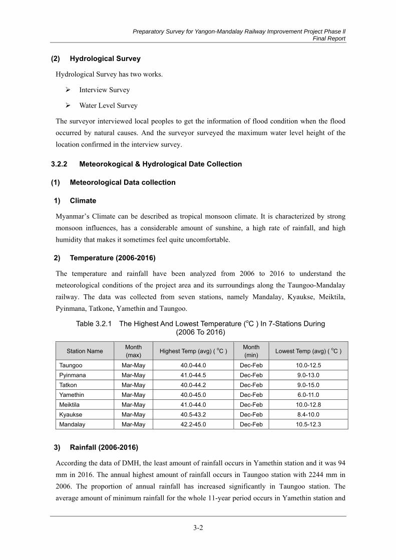
Preparatory Survey for Yangon-Mandalay Railway Improvement Project Phase ll Final Report
3-2
Hydrological Survey (2)
Hydrological Survey has two works.
Interview Survey
Water Level Survey
The surveyor interviewed local peoples to get the information of flood condition when the flood occurred by natural causes. And the surveyor surveyed the maximum water level height of the location confirmed in the interview survey.
Meteorokogical & Hydrological Date Collection 3.2.2
Meteorological Data collection (1)
1) Climate
Myanmar’s Climate can be described as tropical monsoon climate. It is characterized by strong monsoon influences, has a considerable amount of sunshine, a high rate of rainfall, and high humidity that makes it sometimes feel quite uncomfortable.
2) Temperature (2006-2016)
The temperature and rainfall have been analyzed from 2006 to 2016 to understand the meteorological conditions of the project area and its surroundings along the Taungoo-Mandalay railway. The data was collected from seven stations, namely Mandalay, Kyaukse, Meiktila, Pyinmana, Tatkone, Yamethin and Taungoo.
Table 3.2.1 The Highest And Lowest Temperature (oC ) In 7-Stations During (2006 To 2016)
Station Name Month (max) Highest Temp (avg) ( oC ) Month
(min) Lowest Temp (avg) ( oC )
Taungoo Mar-May 40.0-44.0 Dec-Feb 10.0-12.5 Pyinmana Mar-May 41.0-44.5 Dec-Feb 9.0-13.0 Tatkon Mar-May 40.0-44.2 Dec-Feb 9.0-15.0 Yamethin Mar-May 40.0-45.0 Dec-Feb 6.0-11.0 Meiktila Mar-May 41.0-44.0 Dec-Feb 10.0-12.8 Kyaukse Mar-May 40.5-43.2 Dec-Feb 8.4-10.0 Mandalay Mar-May 42.2-45.0 Dec-Feb 10.5-12.3
3) Rainfall (2006-2016)
According the data of DMH, the least amount of rainfall occurs in Yamethin station and it was 94 mm in 2016. The annual highest amount of rainfall occurs in Taungoo station with 2244 mm in 2006. The proportion of annual rainfall has increased significantly in Taungoo station. The average amount of minimum rainfall for the whole 11-year period occurs in Yamethin station and
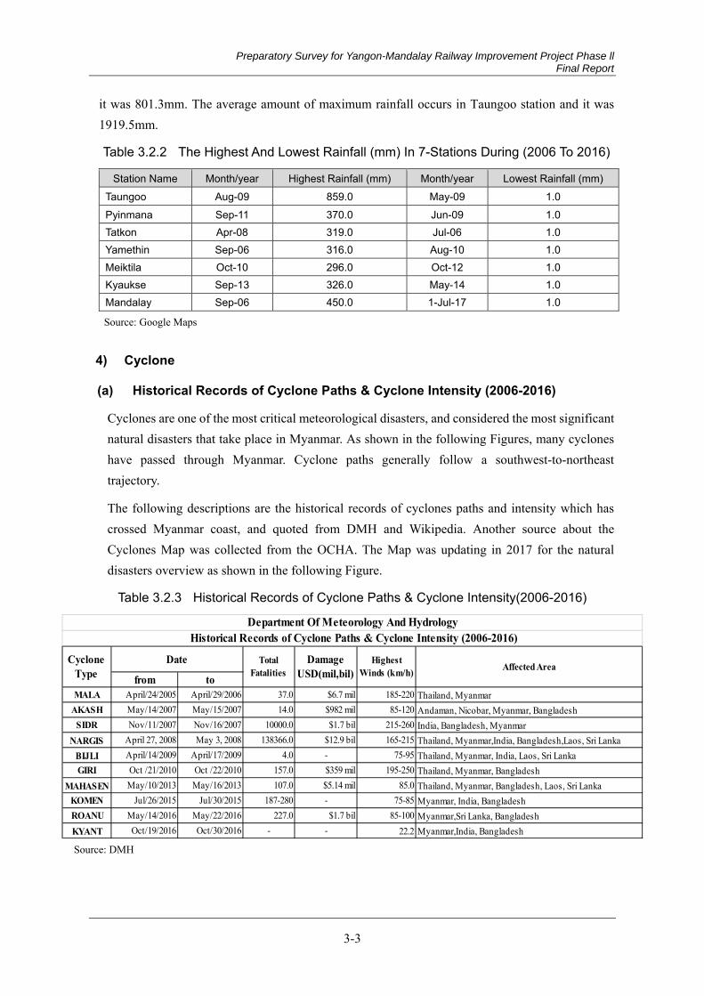
Preparatory Survey for Yangon-Mandalay Railway Improvement Project Phase ll Final Report
3-3
it was 801.3mm. The average amount of maximum rainfall occurs in Taungoo station and it was 1919.5mm.
Table 3.2.2 The Highest And Lowest Rainfall (mm) In 7-Stations During (2006 To 2016)
Station Name Month/year Highest Rainfall (mm) Month/year Lowest Rainfall (mm) Taungoo Aug-09 859.0 May-09 1.0 Pyinmana Sep-11 370.0 Jun-09 1.0 Tatkon Apr-08 319.0 Jul-06 1.0 Yamethin Sep-06 316.0 Aug-10 1.0 Meiktila Oct-10 296.0 Oct-12 1.0 Kyaukse Sep-13 326.0 May-14 1.0 Mandalay Sep-06 450.0 1-Jul-17 1.0
Source: Google Maps
4) Cyclone
(a) Historical Records of Cyclone Paths & Cyclone Intensity (2006-2016)
Cyclones are one of the most critical meteorological disasters, and considered the most significant natural disasters that take place in Myanmar. As shown in the following Figures, many cyclones have passed through Myanmar. Cyclone paths generally follow a southwest-to-northeast trajectory.
The following descriptions are the historical records of cyclones paths and intensity which has crossed Myanmar coast, and quoted from DMH and Wikipedia. Another source about the Cyclones Map was collected from the OCHA. The Map was updating in 2017 for the natural disasters overview as shown in the following Figure.
Table 3.2.3 Historical Records of Cyclone Paths & Cyclone Intensity(2006-2016)
Source: DMH
from toMALA April/24/2005 April/29/2006 37.0 $6.7 mil 185-220
AKASH May/14/2007 May/15/2007 14.0 $982 mil 85-120SIDR Nov/11/2007 Nov/16/2007 10000.0 $1.7 bil 215-260
NARGIS April 27, 2008 May 3, 2008 138366.0 $12.9 bil 165-215BIJLI April/14/2009 April/17/2009 4.0 - 75-95GIRI Oct /21/2010 Oct /22/2010 157.0 $359 mil 195-250
MAHASEN May/10/2013 May/16/2013 107.0 $5.14 mil 85.0KOMEN Jul/26/2015 Jul/30/2015 187-280 - 75-85ROANU May/14/2016 May/22/2016 227.0 $1.7 bil 85-100KYANT Oct/19/2016 Oct/30/2016 - - 22.2
Historical Records of Cyclone Paths & Cyclone Intensity (2006-2016)
Damage USD(mil,bil)
Thailand, Myanmar, BangladeshThailand, Myanmar, Bangladesh, Laos, Sri LankaMyanmar, India, BangladeshMyanmar,Sri Lanka, BangladeshMyanmar,India, Bangladesh
Thailand, MyanmarAndaman, Nicobar, Myanmar, BangladeshIndia, Bangladesh, MyanmarThailand, Myanmar,India, Bangladesh,Laos, Sri LankaThailand, Myanmar, India, Laos, Sri Lanka
Cyclone Type
Date Total Fatalities
Highest Winds (km/h) Affected Area
Department Of Meteorology And Hydrology
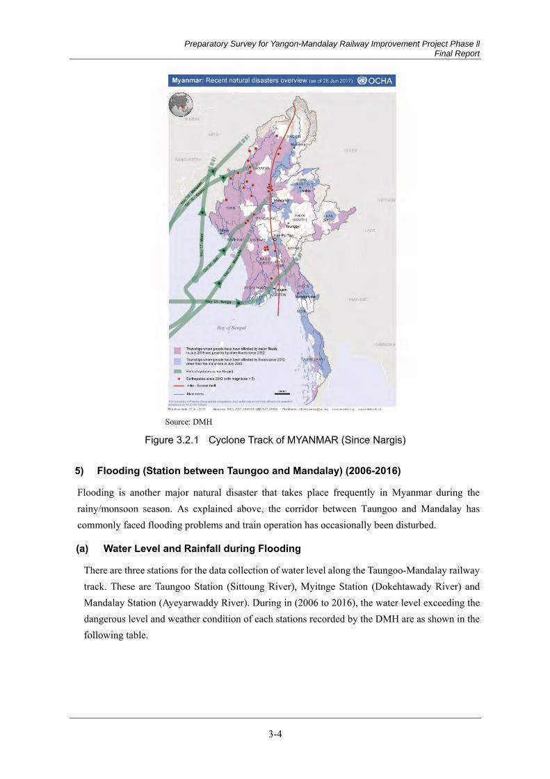
Preparatory Survey for Yangon-Mandalay Railway Improvement Project Phase ll Final Report
3-4
Source: DMH
Figure 3.2.1 Cyclone Track of MYANMAR (Since Nargis)
5) Flooding (Station between Taungoo and Mandalay) (2006-2016)
Flooding is another major natural disaster that takes place frequently in Myanmar during the rainy/monsoon season. As explained above, the corridor between Taungoo and Mandalay has commonly faced flooding problems and train operation has occasionally been disturbed.
(a) Water Level and Rainfall during Flooding
There are three stations for the data collection of water level along the Taungoo-Mandalay railway track. These are Taungoo Station (Sittoung River), Myitnge Station (Dokehtawady River) and Mandalay Station (Ayeyarwaddy River). During in (2006 to 2016), the water level exceeding the dangerous level and weather condition of each stations recorded by the DMH are as shown in the following table.
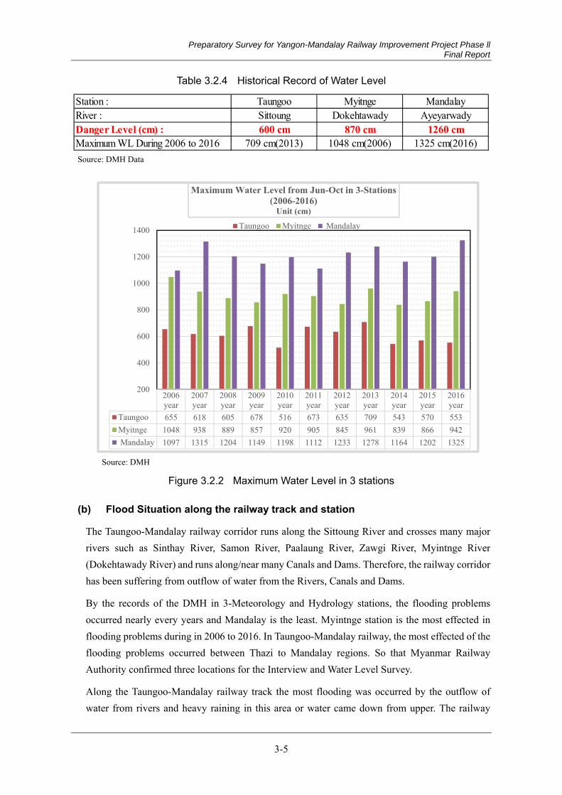
Preparatory Survey for Yangon-Mandalay Railway Improvement Project Phase ll Final Report
3-5
Table 3.2.4 Historical Record of Water Level
Source: DMH Data
Source: DMH
Figure 3.2.2 Maximum Water Level in 3 stations
(b) Flood Situation along the railway track and station
The Taungoo-Mandalay railway corridor runs along the Sittoung River and crosses many major rivers such as Sinthay River, Samon River, Paalaung River, Zawgi River, Myintnge River (Dokehtawady River) and runs along/near many Canals and Dams. Therefore, the railway corridor has been suffering from outflow of water from the Rivers, Canals and Dams.
By the records of the DMH in 3-Meteorology and Hydrology stations, the flooding problems occurred nearly every years and Mandalay is the least. Myintnge station is the most effected in flooding problems during in 2006 to 2016. In Taungoo-Mandalay railway, the most effected of the flooding problems occurred between Thazi to Mandalay regions. So that Myanmar Railway Authority confirmed three locations for the Interview and Water Level Survey.
Along the Taungoo-Mandalay railway track the most flooding was occurred by the outflow of water from rivers and heavy raining in this area or water came down from upper. The railway
Station : Taungoo Myitnge MandalayRiver : Sittoung Dokehtawady AyeyarwadyDanger Level (cm) : 600 cm 870 cm 1260 cmMaximum WL During 2006 to 2016 709 cm(2013) 1048 cm(2006) 1325 cm(2016)
2006year
2007year
2008year
2009year
2010year
2011year
2012year
2013year
2014year
2015year
2016year
Taungoo 655 618 605 678 516 673 635 709 543 570 553Myitnge 1048 938 889 857 920 905 845 961 839 866 942 Mandalay 1097 1315 1204 1149 1198 1112 1233 1278 1164 1202 1325
200
400
600
800
1000
1200
1400
Maximum Water Level from Jun-Oct in 3-Stations (2006-2016)
Unit (cm)Taungoo Myitnge Mandalay

Preparatory Survey for Yangon-Mandalay Railway Improvement Project Phase ll Final Report
3-6
stations in Taungoo to Mandalay are not affected more than the railway bridges or near of the bridges location.
Hydrological Survey (2)
Table 3.2.5 shows the three locations for interview and flood mark survey where were confirmed by the Myanmar Railway authority.
Table 3.2.5 Location of the Interview and Flood Mark Survey
Source: Myanmar Railway
1) Dam Construction along the railway track
Dams are constructed for a specific purpose such as water supply, flood control, irrigation, navigation, sedimentation control, and hydropower. A dam is the cornerstone in the development and management of water resources development of a river basin. By the Irrigation Department data, the following Table shows the lists of dams which located along or near the Taungoo-Mandalay railway area.

Preparatory Survey for Yangon-Mandalay Railway Improvement Project Phase ll Final Report
3-7
Source: MALI
Figure 3.2.3 Location of Dams along the Taungoo-Mandalay railway area and list of dams
2) River Improvement
The purposes of these projects were River Bank Protection, improvement of the old embankment, River Improvement data was collected from the DWIR in Bago Division and Mandalay Division to understand the River Dredging, Excavation and Improvement of River. In Bago Division, DWIR has 8-Locations for the River Improvement. Only two locations are near in Taungoo.
Source: DWIR
Figure 3.2.4 21-Locations of River Improvement
No. River Name Project Name Project Type
Tanaw Kyun Village Timber Spur with rocks inside
Phyu-Oak Pyart-Hmone Highway Timber Spur with rocks inside19-Ward, Dawna Road Timber Spur with rocks insideAung Gyi Village Timber Spur with Sand Bags inside
Pya Thaung Village Timber Spur with Sand Bags insideSteel Basket based Concrete embankmentImprovement of old embankment
Tha Bake Tan Village Concrete embankmentBanaw Village Bore Pile based Concrete embankmentNyaung Pin Thar Village Steel Basket based Concrete embankmentInlyar Village and Kinlat Village Sand Bag based Concrete embankment
Steel Basket based Concrete embankmentSand Bag based Concrete embankment
Shwe Sar Yan Village Steel Basket based Concrete embankmentTaung Kin-Myauk Myay Ward Steel Basket based Concrete embankment
Innwa region Steel Basket based Concrete embankmentOke Kyut Hpo Village Steel Basket based Concrete embankmentOhn Let Kauk Village Steel Basket based Concrete embankmentWonpatace Village Steel Basket based Concrete embankment
Aung Chan Thar Ward Ohn Pin Village, Thayet Pin Village
Timber Spur with Sand Bags inside
Myopyin Thet Taw Ya Pagoda East and Zawdika Sawmill front
Timber Spur
Dokehtawady2
Pannlong 3
Hpa Ye Kyun East and West Village
Thipaw Township
Concrete embankment
1 Sittaung
Thuye Tha Main Village Bend cutting for improvement of waterways and erosion protection
Hlae Swae Myaung Village and Chaung Kyo Village

Preparatory Survey for Yangon-Mandalay Railway Improvement Project Phase ll Final Report
3-8
In Mandalay Division, DWIR have 13-Locations for the River Improvement in Dokehtawady River and Pannlong River. The purposes of these projects were River Bank Protection and.
3.3 Earthquake
Background and Earthquake Zone of Myanmar 3.3.1
Among the natural disasters, an earthquake is one of the most destructive geological hazards that can cause damage, as there are primary effects by ground motion and ground failure, and other secondary effects such as tsunami, landslide, liquefaction and fire. Myanmar is more prone to earthquakes than other Indochina countries due to its seismological location. Tectonically, Myanmar lies in the frontier or convergence zone where two major plates, namely the India Plate (composed of the Indian continent and Indian Ocean) and the Eurasia Plate (comprising Europe, a part of Asia including the Eastern Highlands of Myanmar, and South China Sea) congregate. Sagaing fault has been suggested as the Plate boundary.
This is a tectonically active region and major active faults and fault systems are present almost all over of the country. Under the situation in Alpide earthquake Belt that is one of the two major earthquake belts, thrust transfers current collisional structures overwhelmed the whole country and devastating earthquakes struck the people and infrastructure of Myanmar
Apart from the Sagaing fault, there are thirteen major fault systems and a hundred active faults in Myanmar territory. They are: (1) Kaladan- Mrauk- U fault system; (2) Kabaw fault system; (3) Pyay fault; (4) Yenangyaung thrust; (5) Tangyidaung – Chauk thrust; (6) Tuyin Taung – Gwegyo thrust; (7) West Bago Yoma –Thegon fault system; (8) Shweli fault system;(9)Momeik fault system; (10) Shan Scarp –PaungLaung fault system; (11) Kyaukkyan- Papunfault system; (12) Golden Triangle fault system; and (13) Three Pagodas fault system. Among them, Sagaing fault is the most active and others seem to have a rate of displacement of 5 to 30 percent compared to Sagaing.
The majority of the earthquakes in Myanmar are mainly confined to three zones as follows (Hazard profile of Myanmar 2009):
i) The zone along the western fault belt of Myanmar that has mostly intermediate focus earthquakes. The earthquake frequency is much higher in the northern part.
ii) The zone along the Sagaing fault, including the offshore part with shallow focus earthquakes. The earthquake frequency is much higher in the three segments (from south to north), Bago – Taungoo, Sagaing- Tagaung, and Myitkyina- Putao.
iii) The zone in the north eastern part of Myanmar which is continuous to the earthquake belt in southern Yunnan.
The following Figure 3.3.1 presents the Tectonic Map of Myanmar region (revised in 2007) showing the plates and major fault zones. It also shows active faults that run from north to south in
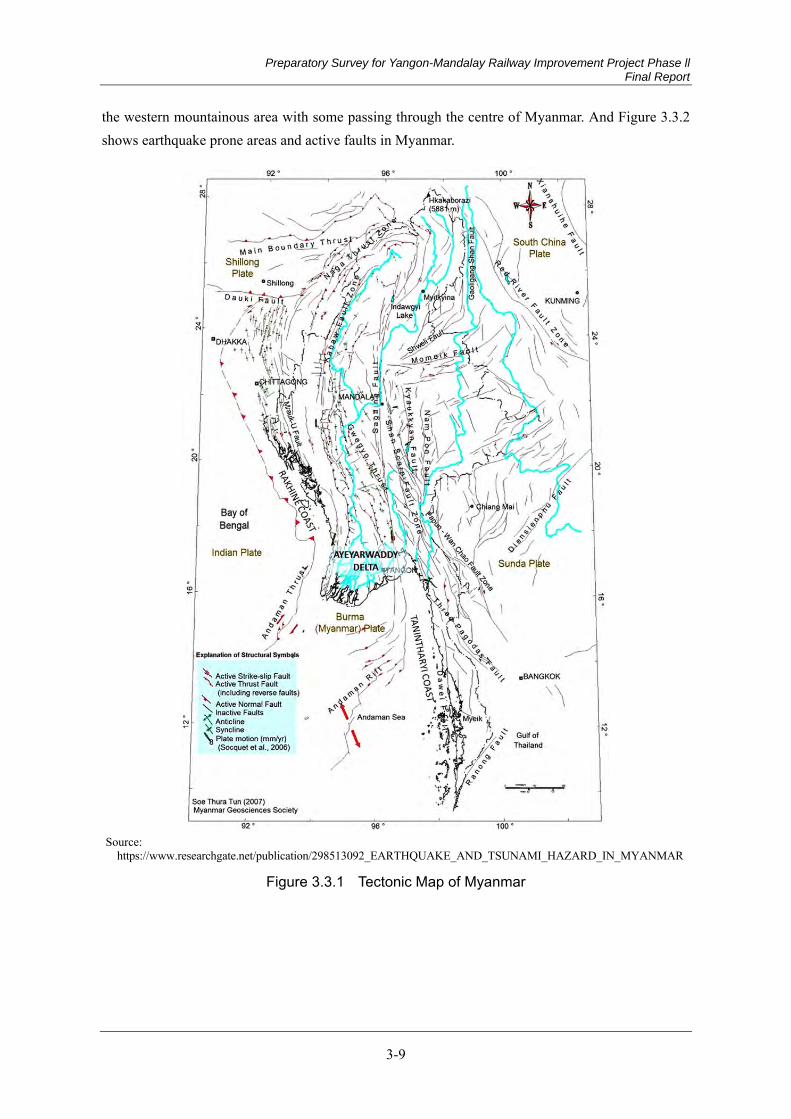
Preparatory Survey for Yangon-Mandalay Railway Improvement Project Phase ll Final Report
3-9
the western mountainous area with some passing through the centre of Myanmar. And Figure 3.3.2 shows earthquake prone areas and active faults in Myanmar.
Source:
https://www.researchgate.net/publication/298513092_EARTHQUAKE_AND_TSUNAMI_HAZARD_IN_MYANMAR
Figure 3.3.1 Tectonic Map of Myanmar

Preparatory Survey for Yangon-Mandalay Railway Improvement Project Phase ll Final Report
3-10
Source : MYT-PLAN based on MIMU
Figure 3.3.2 Earthquake Prone Areas and Active Faults in Myanmar
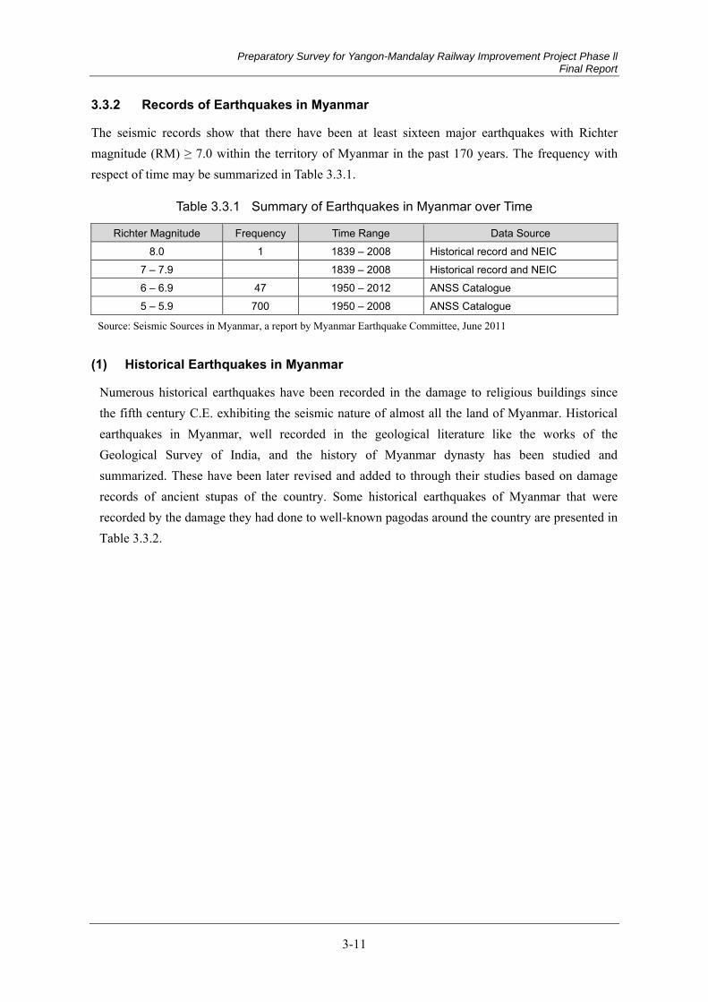
Preparatory Survey for Yangon-Mandalay Railway Improvement Project Phase ll Final Report
3-11
Records of Earthquakes in Myanmar 3.3.2
The seismic records show that there have been at least sixteen major earthquakes with Richter magnitude (RM) ≥ 7.0 within the territory of Myanmar in the past 170 years. The frequency with respect of time may be summarized in Table 3.3.1.
Table 3.3.1 Summary of Earthquakes in Myanmar over Time
Richter Magnitude Frequency Time Range Data Source 8.0 1 1839 – 2008 Historical record and NEIC
7 – 7.9 1839 – 2008 Historical record and NEIC 6 – 6.9 47 1950 – 2012 ANSS Catalogue 5 – 5.9 700 1950 – 2008 ANSS Catalogue
Source: Seismic Sources in Myanmar, a report by Myanmar Earthquake Committee, June 2011
Historical Earthquakes in Myanmar (1)
Numerous historical earthquakes have been recorded in the damage to religious buildings since the fifth century C.E. exhibiting the seismic nature of almost all the land of Myanmar. Historical earthquakes in Myanmar, well recorded in the geological literature like the works of the Geological Survey of India, and the history of Myanmar dynasty has been studied and summarized. These have been later revised and added to through their studies based on damage records of ancient stupas of the country. Some historical earthquakes of Myanmar that were recorded by the damage they had done to well-known pagodas around the country are presented in Table 3.3.2.
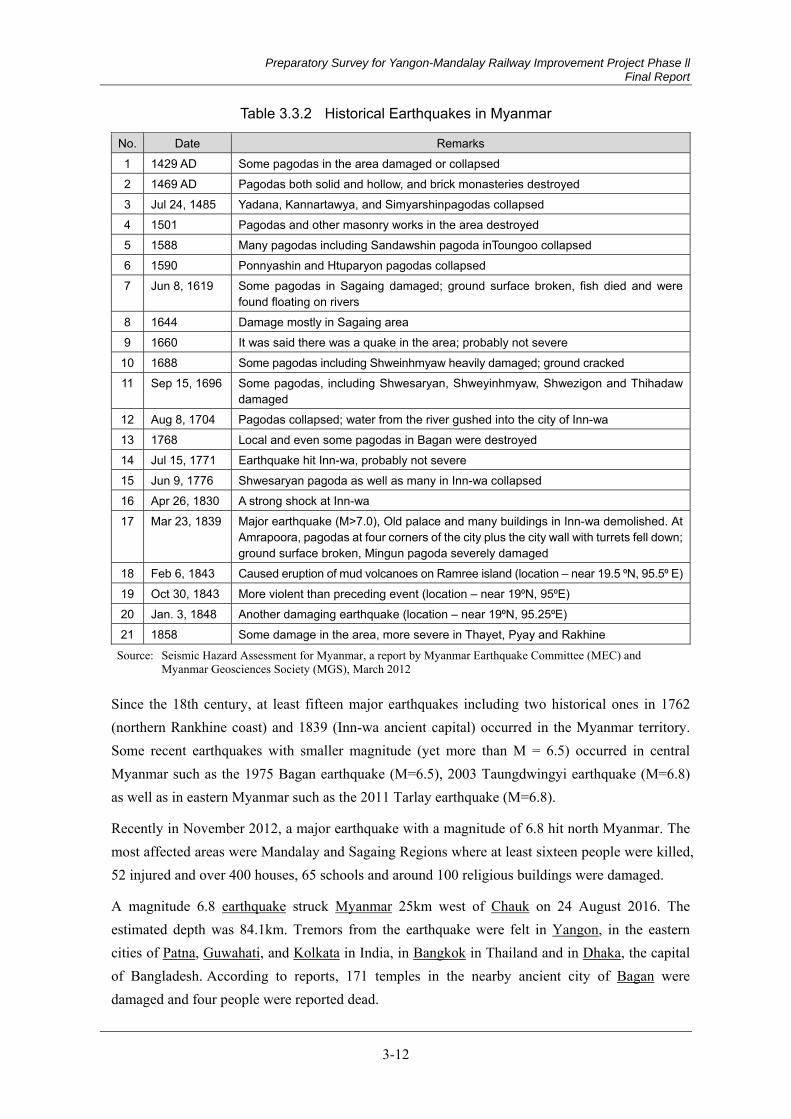
Preparatory Survey for Yangon-Mandalay Railway Improvement Project Phase ll Final Report
3-12
Table 3.3.2 Historical Earthquakes in Myanmar
No. Date Remarks 1 1429 AD Some pagodas in the area damaged or collapsed 2 1469 AD Pagodas both solid and hollow, and brick monasteries destroyed 3 Jul 24, 1485 Yadana, Kannartawya, and Simyarshinpagodas collapsed 4 1501 Pagodas and other masonry works in the area destroyed 5 1588 Many pagodas including Sandawshin pagoda inToungoo collapsed 6 1590 Ponnyashin and Htuparyon pagodas collapsed 7 Jun 8, 1619 Some pagodas in Sagaing damaged; ground surface broken, fish died and were
found floating on rivers 8 1644 Damage mostly in Sagaing area 9 1660 It was said there was a quake in the area; probably not severe
10 1688 Some pagodas including Shweinhmyaw heavily damaged; ground cracked 11 Sep 15, 1696 Some pagodas, including Shwesaryan, Shweyinhmyaw, Shwezigon and Thihadaw
damaged 12 Aug 8, 1704 Pagodas collapsed; water from the river gushed into the city of Inn-wa 13 1768 Local and even some pagodas in Bagan were destroyed 14 Jul 15, 1771 Earthquake hit Inn-wa, probably not severe 15 Jun 9, 1776 Shwesaryan pagoda as well as many in Inn-wa collapsed 16 Apr 26, 1830 A strong shock at Inn-wa 17 Mar 23, 1839 Major earthquake (M>7.0), Old palace and many buildings in Inn-wa demolished. At
Amrapoora, pagodas at four corners of the city plus the city wall with turrets fell down; ground surface broken, Mingun pagoda severely damaged
18 Feb 6, 1843 Caused eruption of mud volcanoes on Ramree island (location – near 19.5 ⁰N, 95.5⁰ E) 19 Oct 30, 1843 More violent than preceding event (location – near 19⁰N, 95⁰E) 20 Jan. 3, 1848 Another damaging earthquake (location – near 19⁰N, 95.25⁰E) 21 1858 Some damage in the area, more severe in Thayet, Pyay and Rakhine
Source: Seismic Hazard Assessment for Myanmar, a report by Myanmar Earthquake Committee (MEC) and Myanmar Geosciences Society (MGS), March 2012
Since the 18th century, at least fifteen major earthquakes including two historical ones in 1762 (northern Rankhine coast) and 1839 (Inn-wa ancient capital) occurred in the Myanmar territory. Some recent earthquakes with smaller magnitude (yet more than M = 6.5) occurred in central Myanmar such as the 1975 Bagan earthquake (M=6.5), 2003 Taungdwingyi earthquake (M=6.8) as well as in eastern Myanmar such as the 2011 Tarlay earthquake (M=6.8).
Recently in November 2012, a major earthquake with a magnitude of 6.8 hit north Myanmar. The most affected areas were Mandalay and Sagaing Regions where at least sixteen people were killed, 52 injured and over 400 houses, 65 schools and around 100 religious buildings were damaged.
A magnitude 6.8 earthquake struck Myanmar 25km west of Chauk on 24 August 2016. The estimated depth was 84.1km. Tremors from the earthquake were felt in Yangon, in the eastern cities of Patna, Guwahati, and Kolkata in India, in Bangkok in Thailand and in Dhaka, the capital of Bangladesh. According to reports, 171 temples in the nearby ancient city of Bagan were damaged and four people were reported dead.

Preparatory Survey for Yangon-Mandalay Railway Improvement Project Phase ll Final Report
3-13
Significant Earthquakes in Myanmar (2)
In Myanmar, considerable high magnitude earthquakes have occurred including some historical ones. Most of the events were > M=7.0 and causing severe damage and large number of casualties. Among these events, some are represented as below:
i) Inn-wa Earthquake – It produced a maximum intensity of MMI XI (Modified Mercalli Intensity Scale). This earthquake wrought fearful destruction in Ava and Amrapura. In addition to the damage to pagodas and temples, approximately 300 to 400 people were killed. Inn-wa has experienced very frequent shocks from the many earthquakes that have taken place here in the past.
ii) Pyay Earthquake - occurred in 1858, with aftershocks, and many houses and tops of Pagodas collapsed.
iii) Earthquakes in Rakhine Coastal Belt– recorded earthquakes were in 1762 in Sittway; in 1843 and 1848 in Kyaukpyu, where many buildings were damaged.
iv) Earthquakes in Upper Myanmar – recorded in 1906 in Putao, 1928 in Htawgaw – recorded damage to stone masonry buildings, 1931 in Kamaing- recorded landslides and rock falls, 1952 in Homalin.
v) Earthquakes in Sagaing- Tagaung Region – recorded in 1485 in Sagaing, 1871 in Mandalay, 1931 in Kaukse – minor cracking of buildings in Mandalay, 1946 in Tagaung, 1956 in Sagaing – several pagodas severely damaged and 40 to 50 people killed.
vi) Earthquakes in Pyinmana- Phyu Region – recorded in 1929 near Taungoo – reported bent railway tracks, bridges and culverts collapsed and loaded trucks overturned (Swa earthquake), 1930 near Khayan – in a zone trending north-south for 37 km south of Bago (on the Sagaing fault line); about 500 people in Bago and 50 people in Yangon were killed, in 1930 near Nyaunglebin – railroad tracks were twisted (Phyu Earthquake) and about 30 people killed; in 1931 in Pyinmana – three brick buildings sustained damages and got badly cracked, tremors were felt from Mandalay to the Bago District
vii) Earthquakes in Central Myanmar – The three largest events were - in 1858 in Pyay; in 1975 in Bagan–several pagodas in Bagan, an ancient city, were damaged and one person was killed; in 2003 in Taungdwingyi – severe damage to rural houses and religious buildings and seven people were killed.
viii) Earthquakes in Bago- Yangon region – on Dec17 1927 in Yangon (intensity of VII based on Rossi Farrell scale) – recorded damage to the city buildings. There have been many other recorded lower intensity earthquakes in the Bago Area (southern portion of the Sagaing fault).
Earthquakes have been recorded in Yangon and the surrounding areas in the years 1568, 1661, 1664, 1668, 1927 and 1970. The 1927 and 1970 earthquakes occurred in Dedaye and there are
Preparatory Survey for Yangon-Mandalay Railway Improvement Project Phase ll Final Report
3-14
records of the destruction of buildings. The Bago Earthquake that took place on May 5, 1930 caused extensive damage in Bago with great loss of life (500 people died). It also caused many deaths and considerable damage to property in Yangon (50 people died). A series of further shocks occurred further north on Dec 3 and 4, 1930, the severest of which wrecked the masonry buildings in the town of Phyu and caused 30 deaths.
Earthquakes in eastern such as the Myanmar–Maymyo Earthquake in 1912 – railway lines were damaged and mass landslides occurred. The railway line crosses the Kyaukkyan fault between miles 450 and 451 (between Hsum-hsai and Nawnghkio) where the foundations of earth banks were cracked and slid down to the west. Tarlay Earthquake –in 2011, an earthquake of M6.8 occurred around Tarlay town; more than 300 timber and poorly constructed brick buildings were damaged and 74 people died.
Figure 3.3.3 below shows the map of the epicentre distribution of the most significant earthquakes that occurred in and around Myanmar from the 18th Century until recently.
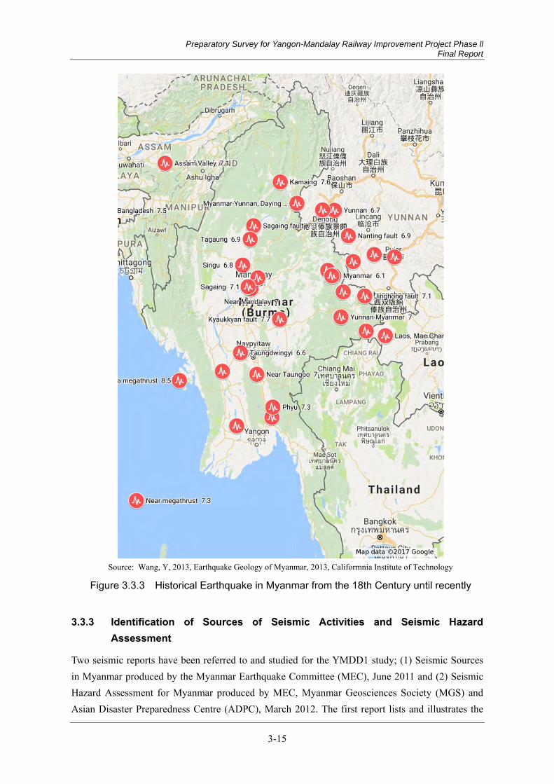
Preparatory Survey for Yangon-Mandalay Railway Improvement Project Phase ll Final Report
3-15
Source: Wang, Y, 2013, Earthquake Geology of Myanmar, 2013, Califormnia Institute of Technology
Figure 3.3.3 Historical Earthquake in Myanmar from the 18th Century until recently
Identification of Sources of Seismic Activities and Seismic Hazard 3.3.3Assessment
Two seismic reports have been referred to and studied for the YMDD1 study; (1) Seismic Sources in Myanmar produced by the Myanmar Earthquake Committee (MEC), June 2011 and (2) Seismic Hazard Assessment for Myanmar produced by MEC, Myanmar Geosciences Society (MGS) and Asian Disaster Preparedness Centre (ADPC), March 2012. The first report lists and illustrates the
Preparatory Survey for Yangon-Mandalay Railway Improvement Project Phase ll Final Report
3-16
earthquakes in Myanmar and aims at identifying seismological sources; the second one provides a seismic hazard analysis. The relevant portions of the two reports are presented below.
In earlier times, a lack of detailed studies on historical earthquake events such as paleo seismological studies made it difficult to have a good understanding of the exact magnitudes, locations and depths of the earthquakes that took place in Myanmar. Recent studies on earthquakes in Myanmar have started since the 2003 Taungdwingyi Earthquake. Geologists from Myanmar Universities were later organized in the Myanmar Earthquake Committee (MEC).
Mitigation was recognized to be vital after Cyclone Nargisthat devastated more than 150,000 lives in Myanmar in 2008. The need for proper earthquake risk assessment was then identified.
Seismically Active Systems (1)
As for the earthquake sources, the major active faults which have been seismically very hazardous for Myanmar have been Sagaing fault, Kyaukkyan fault, Nan Pon fault, Kabaw fault, MyaunkU fault, Dawei fault, Gwegyo thrust, and some major thrusts in north – west Myanmar.
Causes of Earthquakes (2)
In the June 2011 report produced by MEC titled “Seismic Sources in Myanmar”, it was concluded that the subduction zone of the Indian Australian plate and Burma (Eurasia) along the south - western margin and the collision zone of the Indian Plate and Eurasia Plate also caused high magnitude earthquakes (even tsunami generating earthquakes) that happened in the past century. The systems of the strike slip fault in the eastern part of Myanmar also caused some of the high-magnitude disastrous earthquakes, which are now under investigation. The need for seismic hazard analysis and developing a national seismic hazard analysis map for Myanmar was brought out through the report.
Seismic Hazard Assessment 3.3.4
The hazardous effects of earthquakes include both primary and secondary effects, comprising: (1) those resulting directly from a certain level of ground shaking; (2) those on the land surface resulting from fault rupturing or deformation; and (3) those triggered or activated by a certain level of ground motion resulting in tsunami or seiche in the water bodies and landslides. The first one represents the seismic hazards that are mostly described in terms of ground motion parameters such as peak ground acceleration (PGA), peak ground velocity (PGV), peak ground displacement (PGD), and spectral acceleration (SA). Assessment of seismic hazard is the basic prerequisite for the earthquake prone areas to mitigate the hazardous effects, leading to assessment of seismic risks.
Two approaches can be utilized in seismic hazards estimation: deterministic seismic hazards analysis (DSHA); and probabilistic seismic hazards analysis (PSHA). The seismic hazard assessment brought out by MEC in its March 2012 report is the first detailed probabilistic seismic hazard analysis for Myanmar. This has been referred to for the YMDD study.
Preparatory Survey for Yangon-Mandalay Railway Improvement Project Phase ll Final Report
3-17
Ten PSHA maps were produced by the study for Myanmar out of which, the frequently used maps would probably be the PSHA map of 10% probability of exceedance in 50 years. These maps are generally known as the PSHA maps of 500 years recurrence interval. They have been recommended to be used by all city related planners including infrastructure planners. Seismic risk assessment is needed to understand the vulnerability of buildings and urban infrastructure in general.
With an objective of mitigating earthquake hazards in Myanmar, a seismic zone map was prepared in 1959. Earlier, first and second generation maps were being prepared. The present studies by MEC produced the third generation PSHA maps covering the whole country. A seismic zone map of Myanmar (revised in 2005) has been presented in Figure 3.3.4.
Impact of Earthquakes on the Project Area and Use of Collected Data in the 3.3.5Study
The Yangon – Mandalay railway line that is under study lies more or less running along the Sagaing fault. Most of the project area is located in the zone of severe or very severe damage where it is possible to be hit by an earthquake with MM scale of VIII to IX or stronger.
The earthquake data derived from the ‘Seismic Sources in Myanmar’ and ‘Seismic Hazard Assessment for Myanmar’ should therefore be taken into account in designing the civil works and building structures in the study.

Preparatory Survey for Yangon-Mandalay Railway Improvement Project Phase ll Final Report
3-18
Source: AHA CENTRE and Japan International Cooperation Agency, 2015, Country Report Myanmar, pp. 14.
Figure 3.3.4 Seismic Zone Map of Myanmar
3.4 Geotechnical Conditions
Scope of Objective 3.4.1
The soil investigation conducted during this project phase intends to define the subsurface conditions at project site as much as possible to evaluate the requirements of designing the structure.
Scope of Work 3.4.2
The scope of investigation works include three portions; field investigation work, laboratory testing and report preparation. The field investigation work includes soil boring, soil undisturbed sampling, Standard Penetration Test (SPT) and water level measuring
Preparatory Survey for Yangon-Mandalay Railway Improvement Project Phase ll Final Report
3-19
The Project Location 3.4.3
The project area is located at along the existing railway line from Swar Station to Mandalay Station. Total (20) boring points are assigned to conduct for geotechnical survey. The detailed location of project area is indicated in the geological map Figure 3.4.1.
Topography 3.4.4
Generally, the project area (existing of Yangon-Mandalay Railway Line) is situated at Central Lowlands of tectonic provinces of Myanmar, and between the Bago-Yoma Ranges in the West and the Shan Scarp in the East.
Sittaung River, Zawgyi River, Sin Thay Chaung and other no distinct small streams are flowing along the project area. The most occurrence of drainage system is dendritic system.
Regional Geologic Setting 3.4.5
Refer to the geological map from Geology of Burma, published by Friedrich Bender in 1983, along the project area especially existing Yangon-Mandalay Railway Line, the sediments are of Miocene, Oligocene, Eocene and small amount of Paleocene. The overburden soil layer of the project area is Quaternary Alluvial deposit (Q2), Pleistocene Older Alluvium and Gravels (Q1), and Miocene – Pliocene Irrawaddy Formation (Tm-Tp).
By boring results of soil investigation, the project area is made up of alluvial deposit of CLAY, Sandy CLAY, Clayey SAND and Silty SAND. According to the geological map, the regional geological setting of the stratigraphic succession of project area is as follow-
Description Symbols Age Alluvium Q2 Quaternary Older Alluvium and Gravels Q1 Pleistocene Irrawaddy Formation Tm-Tp Miocene – Pliocene
Preparatory Survey for Yangon-Mandalay Railway Improvement Project Phase ll Final Report
3-20
Classification of soil layer 3.4.6
The soil layers are classified in accordance with their physical properties and/or their relative density. Generally nine different layers observed from BH-01 to BH-20 are described from top to bottom as follows.
1) Filled Soil
2) CLAY-I
3) Silty SAND-I
4) CLAY-II
5) Silty SAND-II
6) CLAY-III
7) Silty SAND-III
8) CLAY-IV
9) Silty SAND-IV
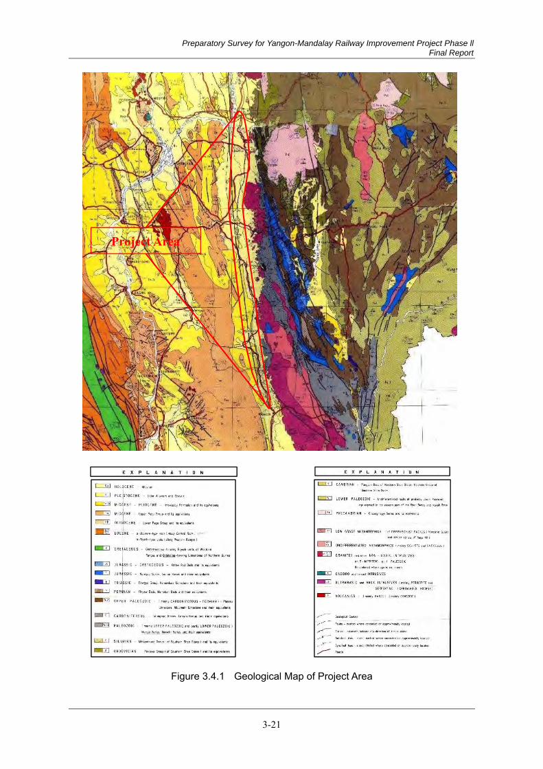
Preparatory Survey for Yangon-Mandalay Railway Improvement Project Phase ll Final Report
3-21
Figure 3.4.1 Geological Map of Project Area
Project Area

Preparatory Survey for Yangon-Mandalay Railway Improvement Project Phase ll Final Report
3-22
FIELD INVESTIGATION 3.4.7
Investigation works (1)
The objective of the present investigation is to identify the general stratification of the ground and the nature of the soil. Total twenty boring points were planned to investigate by the client’s requirements. The field investigation included soil boring with the performing of the test associated with Standard Penetration Test (SPT), Disturbed Soil Sampling, Undisturbed Soil Sampling, Water Level Measuring and Water Sampling. Total boring length is 712.0m and the total quantity of investigation work is listed in Table 3.4.1.
Table 3.4.1 Total Quantity of Boring Works
No. BH. No. Soil Drilling (m) Standard
PenetrationTest (Nos)
Undisturbed Sampling
(Nos)
Water Sample(Nos) Ø 112 mm Ø 64 mm Total
1 BH-01 3.0 43.5 46.5 31 4 1 2 BH-02 3.0 33.5 36.5 24 5 1 3 BH-03 3.0 51.5 54.5 36 5 1 4 BH-04 3.0 21.0 24.0 16 2 1 5 BH-05 3.0 50.0 53.0 35 2 1 6 BH-06 3.0 26.0 29.0 19 1 1 7 BH-07 6.0 42.5 48.5 32 4 1 8 BH-08 4.0 26.5 30.5 20 2 1 9 BH-09 4.0 26.0 30.0 20 1 1 10 BH-10 4.0 23.5 27.5 18 1 1 11 BH-11 3.0 36.0 39.0 25 3 1 12 BH-12 5.0 51.0 56.0 37 1 1 13 BH-13 3.0 25.5 28.5 19 - 1 14 BH-14 5.0 24.0 29.0 19 2 1 15 BH-15 3.0 25.5 28.5 18 3 1 16 BH-16 4.0 23.0 27.0 18 3 1 17 BH-17 8.0 13.0 21.0 13 1 1 18 BH-18 4.0 31.0 35.0 23 - 1 19 BH-19 3.0 36.5 39.5 26 1 1 20 BH-20 3.0 25.5 28.5 19 2 1
Total 77.0 635.0 712.0 468 43 20
Location of Boring Points (2)
The locations of investigated points were designated by client. The plan map showing geotechnical investigated points are indicated in Figure 3.4.2. Moreover, elevation of all boring points was referred from Google earth.
Standard Penetration Test (SPT) (3)
The distribution of SPT N-value and depth in elevation for each stratum is summarized in Figure 3.4.3.
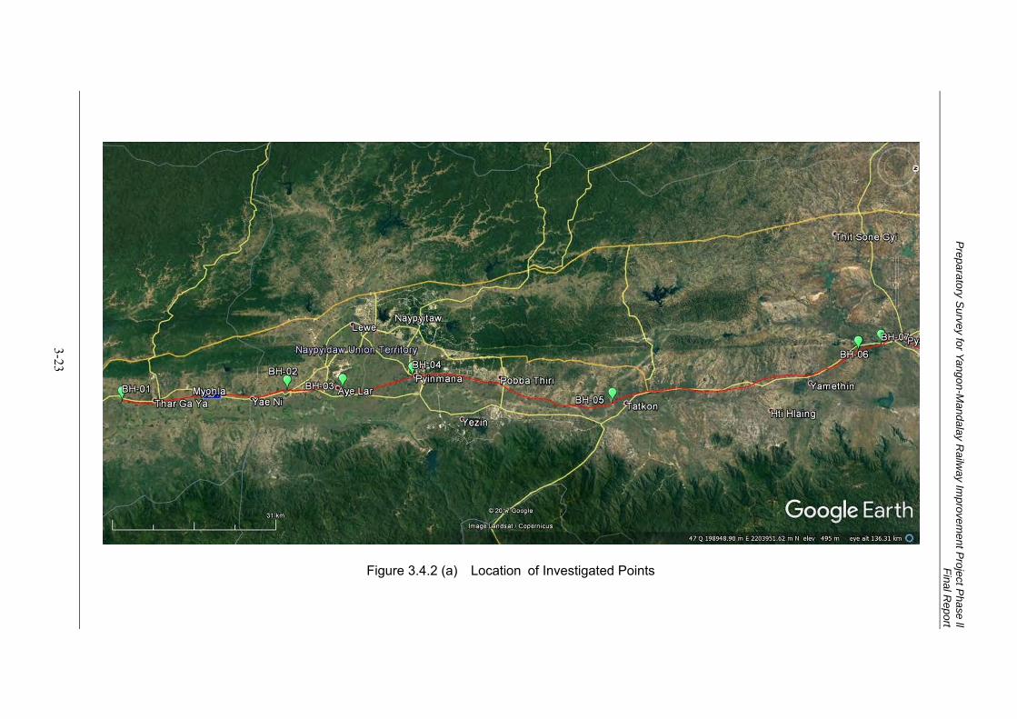
Preparatory S
urvey for Yangon-Mandalay R
ailway Im
provement P
roject Phase ll
Final Report
3-23
Figure 3.4.2 (a) Location of Investigated Points
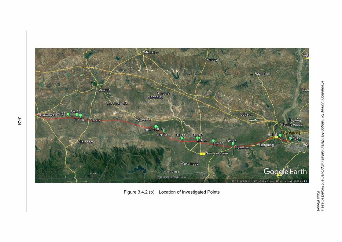
Preparatory S
urvey for Yangon-Mandalay R
ailway Im
provement P
roject Phase ll
Final Report
3-24
Figure 3.4.2 (b) Location of Investigated Points
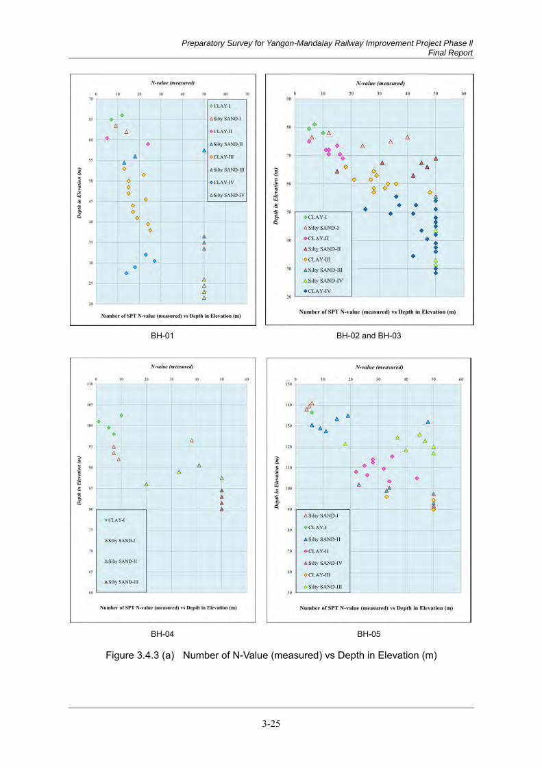
Preparatory Survey for Yangon-Mandalay Railway Improvement Project Phase ll Final Report
3-25
BH-01 BH-02 and BH-03
BH-04 BH-05
Figure 3.4.3 (a) Number of N-Value (measured) vs Depth in Elevation (m)
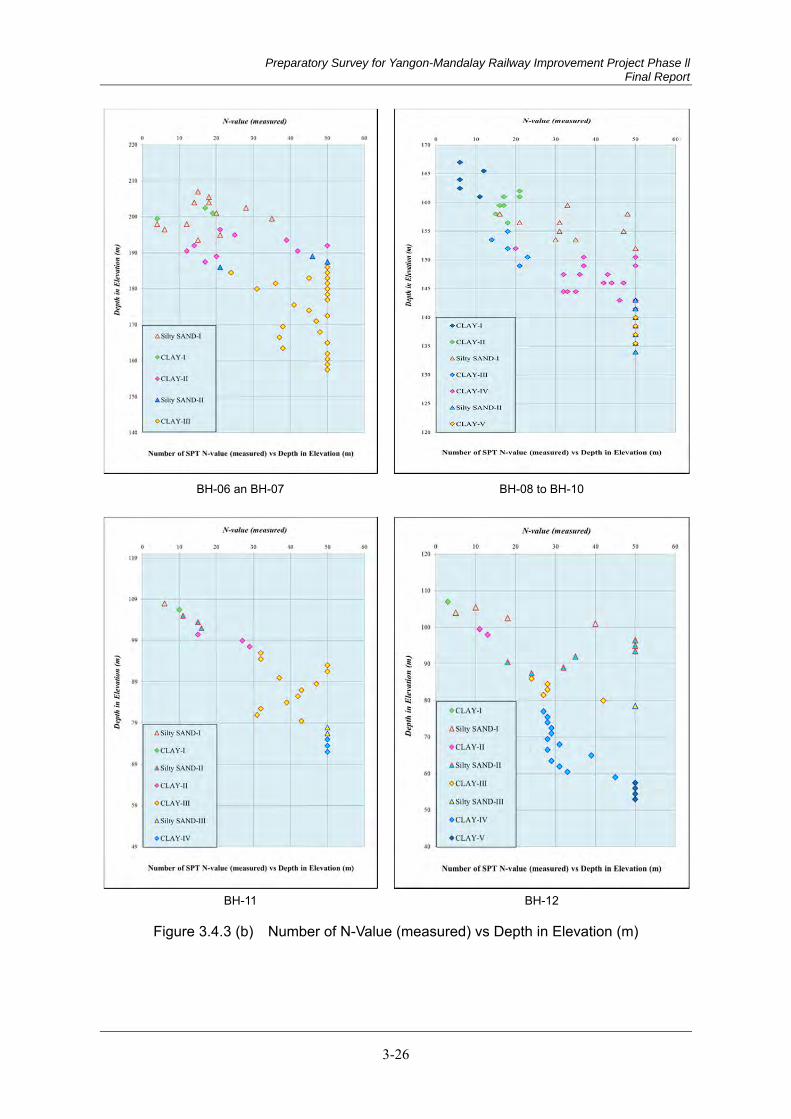
Preparatory Survey for Yangon-Mandalay Railway Improvement Project Phase ll Final Report
3-26
BH-06 an BH-07 BH-08 to BH-10
BH-11 BH-12
Figure 3.4.3 (b) Number of N-Value (measured) vs Depth in Elevation (m)
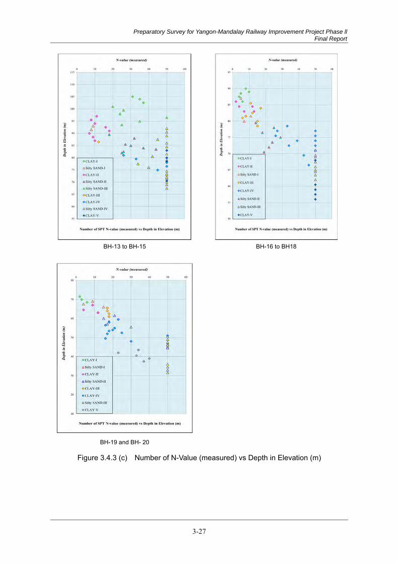
Preparatory Survey for Yangon-Mandalay Railway Improvement Project Phase ll Final Report
3-27
BH-13 to BH-15
BH-16 to BH18
BH-19 and BH- 20
Figure 3.4.3 (c) Number of N-Value (measured) vs Depth in Elevation (m)
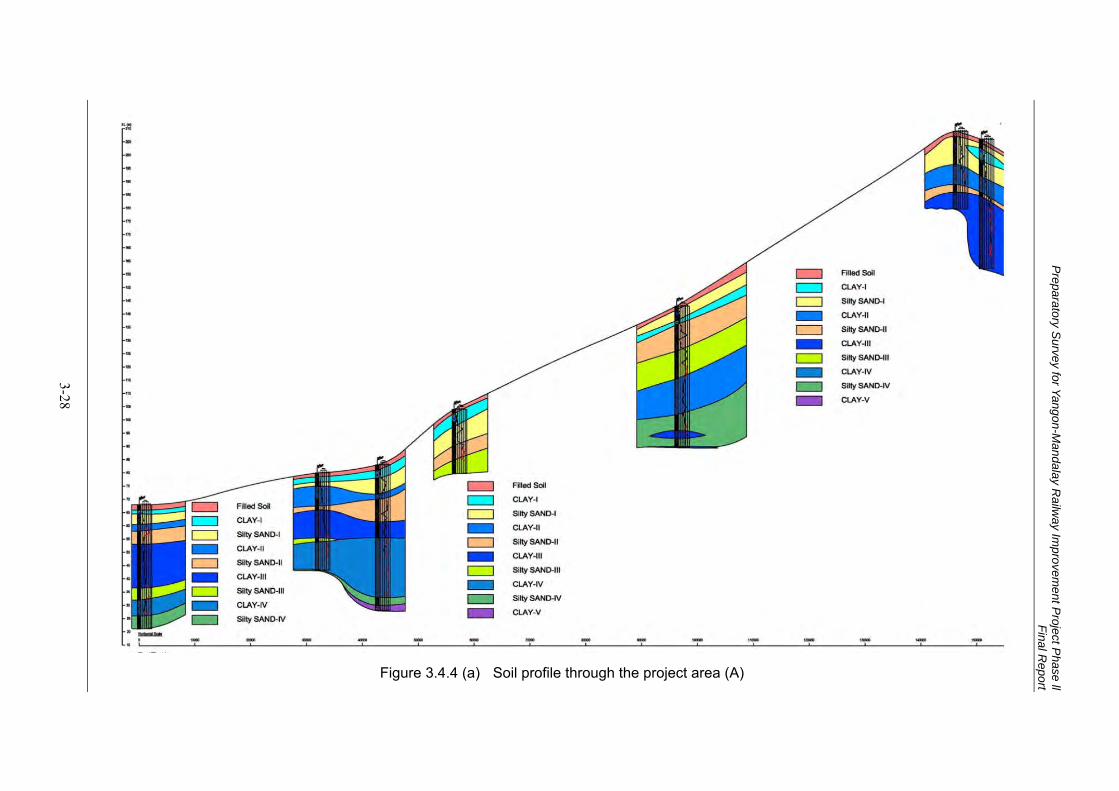
Preparatory S
urvey for Yangon-Mandalay R
ailway Im
provement P
roject Phase ll
Final Report
3-28
Figure 3.4.4 (a) Soil profile through the project area (A)
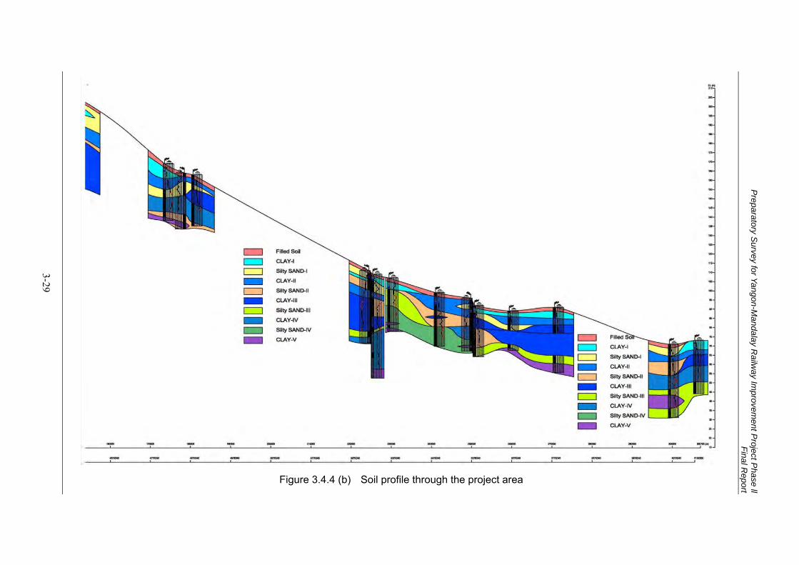
Preparatory S
urvey for Yangon-Mandalay R
ailway Im
provement P
roject Phase ll
Final Report
3-29
Figure 3.4.4 (b) Soil profile through the project area
Preparatory Survey for Yangon-Mandalay Railway Improvement Project Phase ll Final Report
3-30
LABORATORY TEST 3.4.8
There have been twenty numbers of investigation boreholes and total (468) numbers of disturbed samples and (43) numbers of undisturbed samples with Denison sampler and Piston sampler were collected in project site. Some selected numbers of disturbed samples and all undisturbed samples were sent to office laboratory and purposed to test physical and mechanical properties of soil in consulting with expert’s discretion. The entire tests were carried out in accordance with ASTM Standard.
The physical properties tests include the following items.
Natural Moisture Content Test (ASTM D 2216-05)
Specific Gravity Test (ASTM D 854-06)
Particle Size Analysis Test (ASTM D 422-63)
Grain Size Distribution Test
Hydrometer Test o Atterberg Limits Test (ASTM D 4318-05)
Liquid Limit Test
Plastic Limit Test
The mechanical properties tests include the following items.
Unconfined Compression Test (ASTM D 2166-06)
One Dimensional Consolidation Test (ASTM D 2435-04)
Total quantity of laboratory tests are described in Table 3.4.2.
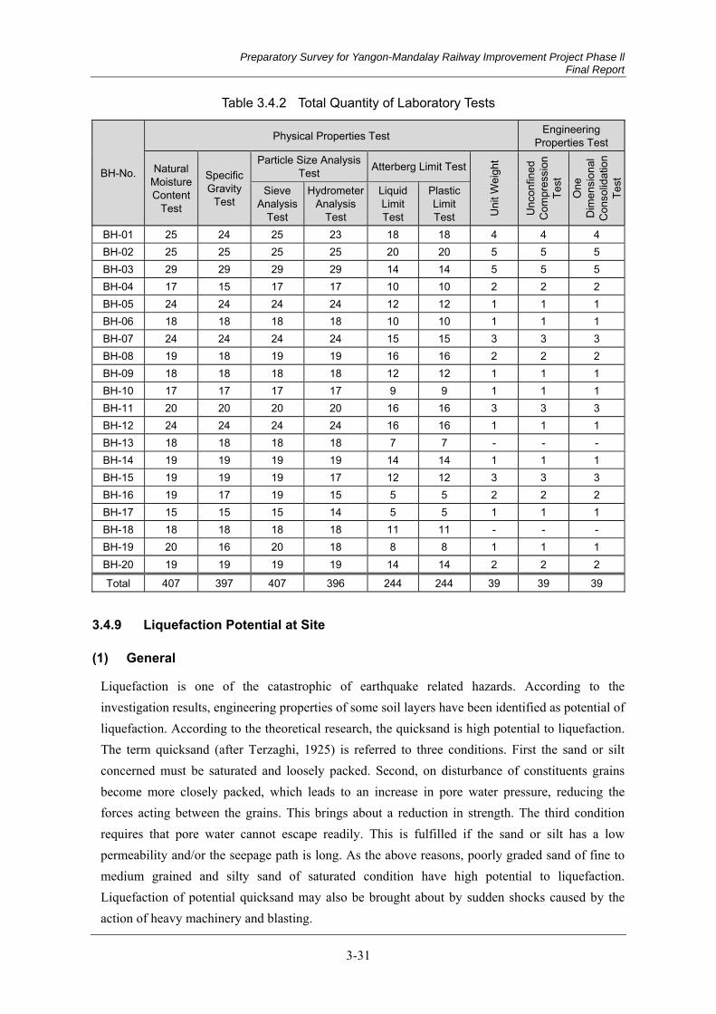
Preparatory Survey for Yangon-Mandalay Railway Improvement Project Phase ll Final Report
3-31
Table 3.4.2 Total Quantity of Laboratory Tests
BH-No.
Physical Properties Test Engineering Properties Test
Natural Moisture Content
Test
Specific Gravity
Test
Particle Size Analysis Test Atterberg Limit Test
Uni
t Wei
ght
Unc
onfin
ed
Com
pres
sion
Te
st
One
D
imen
sion
al
Con
solid
atio
n Te
st
Sieve Analysis
Test
HydrometerAnalysis
Test
Liquid Limit Test
Plastic Limit Test
BH-01 25 24 25 23 18 18 4 4 4 BH-02 25 25 25 25 20 20 5 5 5 BH-03 29 29 29 29 14 14 5 5 5 BH-04 17 15 17 17 10 10 2 2 2 BH-05 24 24 24 24 12 12 1 1 1 BH-06 18 18 18 18 10 10 1 1 1 BH-07 24 24 24 24 15 15 3 3 3 BH-08 19 18 19 19 16 16 2 2 2 BH-09 18 18 18 18 12 12 1 1 1 BH-10 17 17 17 17 9 9 1 1 1 BH-11 20 20 20 20 16 16 3 3 3 BH-12 24 24 24 24 16 16 1 1 1 BH-13 18 18 18 18 7 7 - - - BH-14 19 19 19 19 14 14 1 1 1 BH-15 19 19 19 17 12 12 3 3 3 BH-16 19 17 19 15 5 5 2 2 2 BH-17 15 15 15 14 5 5 1 1 1 BH-18 18 18 18 18 11 11 - - - BH-19 20 16 20 18 8 8 1 1 1 BH-20 19 19 19 19 14 14 2 2 2
Total 407 397 407 396 244 244 39 39 39
Liquefaction Potential at Site 3.4.9
General (1)
Liquefaction is one of the catastrophic of earthquake related hazards. According to the investigation results, engineering properties of some soil layers have been identified as potential of liquefaction. According to the theoretical research, the quicksand is high potential to liquefaction. The term quicksand (after Terzaghi, 1925) is referred to three conditions. First the sand or silt concerned must be saturated and loosely packed. Second, on disturbance of constituents grains become more closely packed, which leads to an increase in pore water pressure, reducing the forces acting between the grains. This brings about a reduction in strength. The third condition requires that pore water cannot escape readily. This is fulfilled if the sand or silt has a low permeability and/or the seepage path is long. As the above reasons, poorly graded sand of fine to medium grained and silty sand of saturated condition have high potential to liquefaction. Liquefaction of potential quicksand may also be brought about by sudden shocks caused by the action of heavy machinery and blasting.
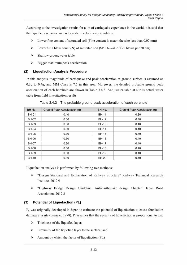
Preparatory Survey for Yangon-Mandalay Railway Improvement Project Phase ll Final Report
3-32
According to the investigation results for a lot of earthquake experience in the world, it is said that the liquefaction can occur easily under the following condition.
Lower fine content of saturated soil (Fine content is meant the size less than 0.07 mm)
Lower SPT blow count (N) of saturated soil (SPT N-value < 20 blows per 30 cm)
Shallow groundwater table
Bigger maximum peak acceleration
Liquefaction Analysis Procedure (2)
In this analysis, magnitude of earthquake and peak acceleration at ground surface is assumed as 0.3g to 0.4g, and MM Class is 7.5 in this area. Moreover, the detailed probable ground peak acceleration of each borehole are shown in Table 3.4.3. And, water table at site is actual water table from field investigation results.
Table 3.4.3 The probable ground peak acceleration of each borehole
BH No. Ground Peak Acceleration (g) BH No. Ground Peak Acceleration (g) BH-01 0.40 BH-11 0.30 BH-02 0.30 BH-12 0.40 BH-03 0.30 BH-13 0.40 BH-04 0.30 BH-14 0.40 BH-05 0.30 BH-15 0.40 BH-06 0.30 BH-16 0.40 BH-07 0.30 BH-17 0.40 BH-08 0.30 BH-18 0.40 BH-09 0.30 BH-19 0.40 BH-10 0.30 BH-20 0.40
Liquefaction analysis is performed by following two methods:
“Design Standard and Explanation of Railway Structure” Railway Technical Research Institute, 2012.9
“Highway Bridge Design Guideline, Anti-earthquake design Chapter” Japan Road Association, 2012.3
Potential of Liquefaction (PL) (3)
PL was originally developed in Japan to estimate the potential of liquefaction to cause foundation damage at a site (Iwasaki, 1978). PL assumes that the severity of liquefaction is proportional to the:
Thickness of the liquefied layer;
Proximity of the liquefied layer to the surface; and
Amount by which the factor of liquefaction (FL)
Preparatory Survey for Yangon-Mandalay Railway Improvement Project Phase ll Final Report
3-33
The potential of liquefaction can be calculated by following formula;
1 10 0.5
Where,
PL = potential of liquefaction
FL = factor of liquefaction
z = Depth in meters
Potential of liquefaction condition is shown in Table 3.4.4
Table 3.4.4 Potential of Liquefaction condition
15 < PL High Possibility of Liquefaction 5 < PL ≤ 15 Possibility of Liquefaction 0 < PL ≤ 5 Low Possibility of Liquefaction
Liquefaction Analysis Results (4)
Summary of liquefaction analysis results are shown in Figure 3.4.5 and Figure 3.4.6. The result analyzed by “Railway structure design” and “Highway Road Bridge Design” is shown respectively. Result of liquefaction result is shown in Figure 3.4.7.
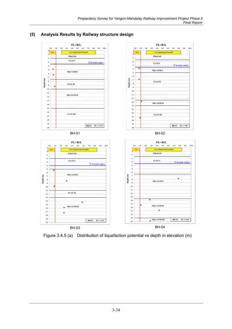
Preparatory Survey for Yangon-Mandalay Railway Improvement Project Phase ll Final Report
3-34
Analysis Results by Railway structure design (5)
BH-01
BH-02
BH-03
BH-04
Figure 3.4.5 (a) Distribution of liquefaction potential vs depth in elevation (m)

Preparatory Survey for Yangon-Mandalay Railway Improvement Project Phase ll Final Report
3-35
BH-05
BH-06
BH-07
BH-08
Figure 3.4.5 (b) Distribution of liquefaction potential vs depth in elevation (m)
Preparatory Survey for Yangon-Mandalay Railway Improvement Project Phase ll Final Report
3-36
BH-09
BH-10
BH-11
BH-12
Figure 3.4.5 (c) Distribution of liquefaction potential vs depth in elevation (m)
Preparatory Survey for Yangon-Mandalay Railway Improvement Project Phase ll Final Report
3-37
BH-13
BH-14
BH-15
BH-16
Figure 3.4.5 (d) Distribution of liquefaction potential vs depth in elevation (m)
Preparatory Survey for Yangon-Mandalay Railway Improvement Project Phase ll Final Report
3-38
BH-17
BH-18
BH-17
BH-17
Figure 3.4.5 (e) Distribution of liquefaction potential vs depth in elevation (m)
Preparatory Survey for Yangon-Mandalay Railway Improvement Project Phase ll Final Report
3-39
Analysis Results by Highway Bridge Design Guideline (6)
BH-01 BH-02
BH-03
BH-04
Figure 3.4.6 (a) Distribution of liquefaction potential vs depth in elevation (m)

Preparatory Survey for Yangon-Mandalay Railway Improvement Project Phase ll Final Report
3-40
BH-05
BH-06
BH-07
BH-08
Figure 3.4.6 (b) Distribution of liquefaction potential vs depth in elevation (m)
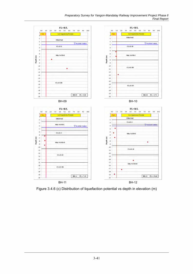
Preparatory Survey for Yangon-Mandalay Railway Improvement Project Phase ll Final Report
3-41
BH-09
BH-10
BH-11
BH-12
Figure 3.4.6 (c) Distribution of liquefaction potential vs depth in elevation (m)
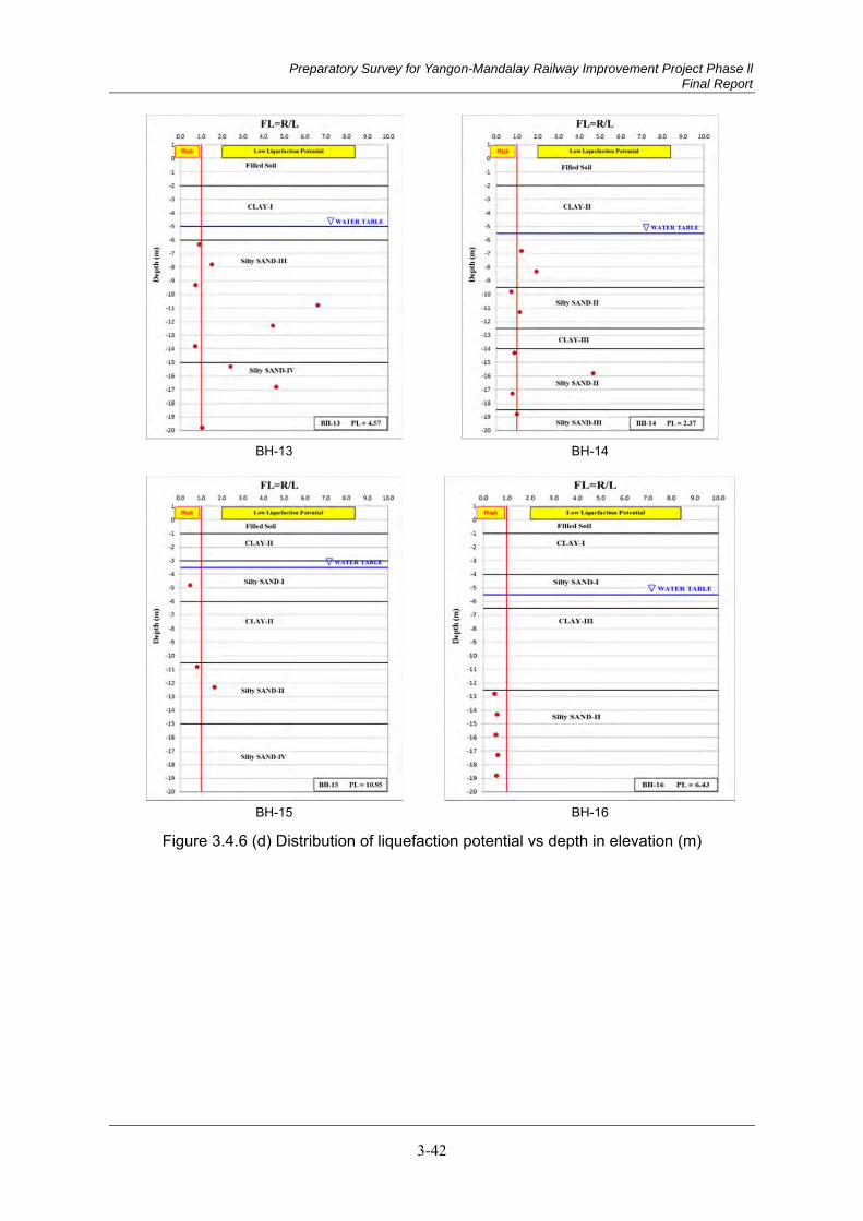
Preparatory Survey for Yangon-Mandalay Railway Improvement Project Phase ll Final Report
3-42
BH-13
BH-14
BH-15
BH-16
Figure 3.4.6 (d) Distribution of liquefaction potential vs depth in elevation (m)
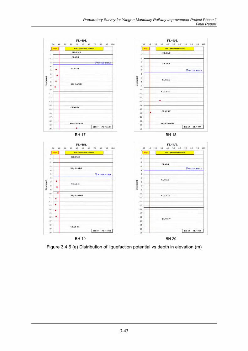
Preparatory Survey for Yangon-Mandalay Railway Improvement Project Phase ll Final Report
3-43
BH-17
BH-18
BH-19
BH-20
Figure 3.4.6 (e) Distribution of liquefaction potential vs depth in elevation (m)
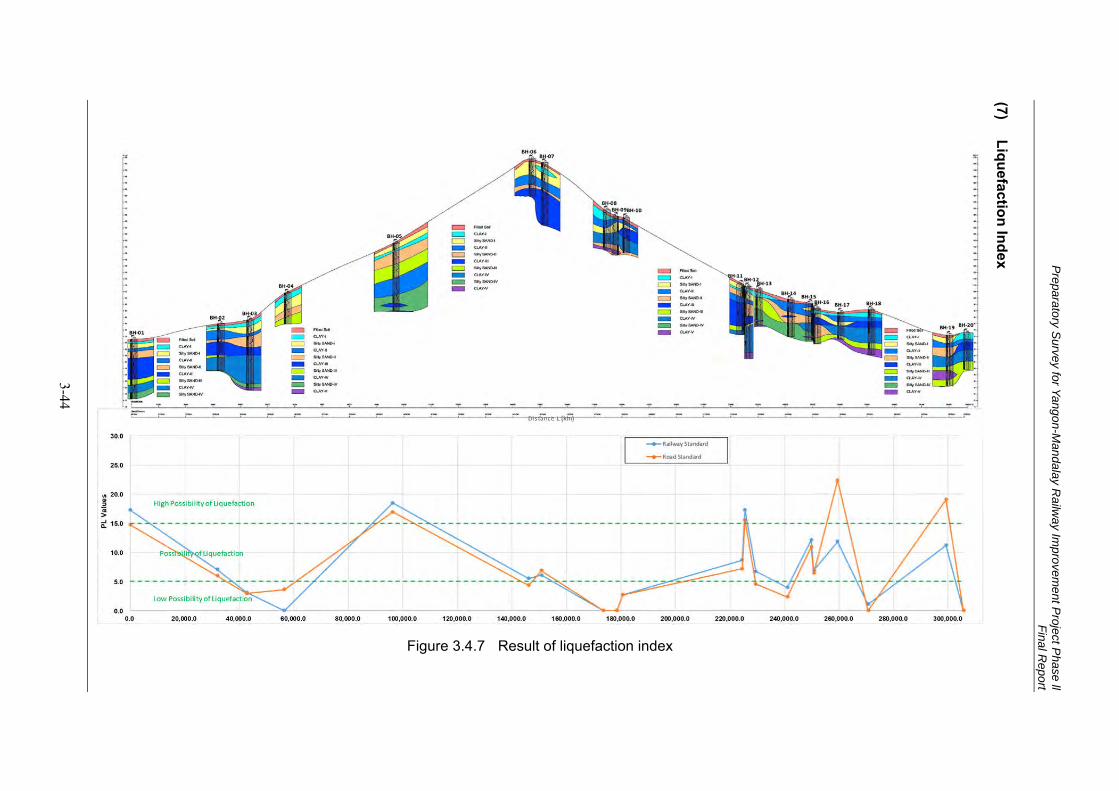
Preparatory S
urvey for Yangon-Mandalay R
ailway Im
provement P
roject Phase ll
Final Report
3-44
Liquefaction Index
(7)
Figure 3.4.7 Result of liquefaction index
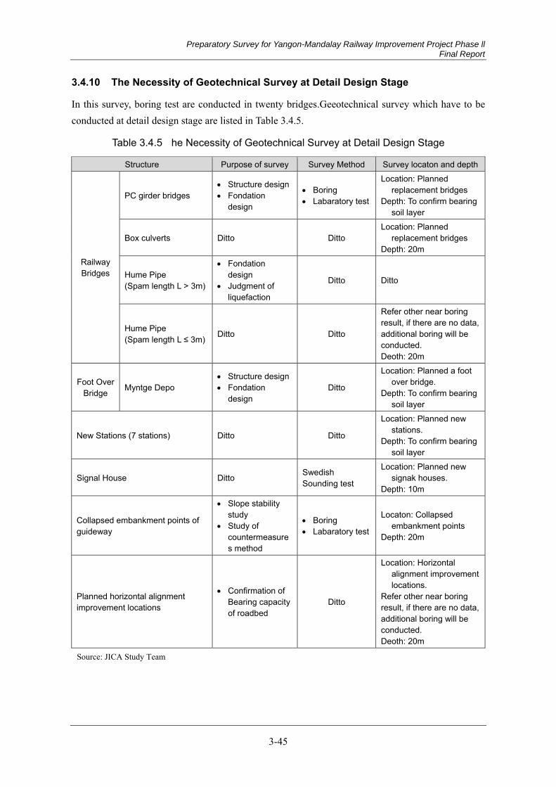
Preparatory Survey for Yangon-Mandalay Railway Improvement Project Phase ll Final Report
3-45
The Necessity of Geotechnical Survey at Detail Design Stage 3.4.10
In this survey, boring test are conducted in twenty bridges.Geeotechnical survey which have to be conducted at detail design stage are listed in Table 3.4.5.
Table 3.4.5 he Necessity of Geotechnical Survey at Detail Design Stage
Structure Purpose of survey Survey Method Survey locaton and depth
Railway Bridges
PC girder bridges Structure design Fondation
design
Boring Labaratory test
Location: Planned replacement bridges
Depth: To confirm bearing soil layer
Box culverts Ditto Ditto Location: Planned
replacement bridges Depth: 20m
Hume Pipe (Spam length L > 3m)
Fondation design
Judgment of liquefaction
Ditto Ditto
Hume Pipe (Spam length L ≤ 3m) Ditto Ditto
Refer other near boring result, if there are no data, additional boring will be conducted. Deoth: 20m
Foot Over Bridge Myntge Depo
Structure design Fondation
design Ditto
Location: Planned a foot over bridge.
Depth: To confirm bearing soil layer
New Stations (7 stations) Ditto Ditto
Location: Planned new stations.
Depth: To confirm bearing soil layer
Signal House Ditto Swedish Sounding test
Location: Planned new signak houses.
Depth: 10m
Collapsed embankment points of guideway
Slope stability study
Study of countermeasures method
Boring Labaratory test
Locaton: Collapsed embankment points
Depth: 20m
Planned horizontal alignment improvement locations
Confirmation of Bearing capacity of roadbed
Ditto
Location: Horizontal alignment improvement locations.
Refer other near boring result, if there are no data, additional boring will be conducted. Deoth: 20m
Source: JICA Study Team
Preparatory Survey for Yangon-Mandalay Railway Improvement Project Phase ll Final Report
4-1
Chapter 4 Railway System Parameters and Outline of Design Conditions
4.1 General
The purpose of rehabilitation and modernization for the existing railway facilities from Tangoo station to Mandalay are,
(1) Increasing passenger and freight transport capacity between Yangon-Mandalay to cope with increase traffic demand;
(2) Increasing the train operation speed;
(3) Reducing travel time;
(4) Increasing safety, reliability and punctuality of train operation and;
(5) Enhancing the national economic growth such as industries, trade, and commercial etc
The Railway Improvement Plan is as shown in table below.
Table 4.1.1 Railway Improvement Plan for the Project
No Parameter Existing Line (2017) Improved Main Line (2023) Remarks 1 Gauge: Double Tracks 1,000mm 1,000mm 2 Length (km) 353km 353km 3 Traction Power Non-electrified Non-electrified 4 Axle Load for DEMU less than 12.5ton less than 20ton
5 Construction Gauge / Rolling Stock Gauge
Construction Gauge a. Height 3,810mm 4,300mm b. Width 3,810mm 3,810mm
Rolling Stock gauge c. Height 3,505mm 4,100mm d. Width 2,818mm 3,000mm 6 Horizontal curvature
a. Minimum radius 300m Design Criteria 500m
Design minimum value 300m

Preparatory Survey for Yangon-Mandalay Railway Improvement Project Phase ll Final Report
4-2
No Parameter Existing Line (2017) Improved Main Line (2023) Remarks 7 Vertical alignment
a. Maximum gradient 6‰ 10‰ Desirable 6‰
8 Number of Stations 55 50 including Halt Station
9 Traffic Volume (Passenger-km/day)
2,089,247 (Estimated value in 2013) 10,190,618
Yangon-Mandalay whole section
10 Daily Ridership (No. of Passenger)
22,500 (Estimated value in 2013) 80,700
11 Total number of Train per day 28 104 Trains on YM Line
Only (Trains going to/from branch lines are excluded)
a. Express Train 5 round trips
35 round trips b. Local Train (including
Mail trains) 5 round trips
12 Speed a. Maximum 48 - 69 kph 100 kph (DEMU) b. Schedule 44 kph 77.5 kph or more
13 Rolling Stock (Passenger Train)
a. Train composition and No. of Car 1 DEL + 14 coaches (max) 6 cars + 6 cars
14 Safety System
a. Type of Signalling Relay Interlocking Mechanical Interlocking
Relay Interlocking Electronic Interlocking
b. Train Control System Absolute Block System Absolute Block System
Automatic Block System
c. Level Crossing Manual Operated Level
Crossing (97 crossings)
Automatic Level Crossing (79)
Manual Level Crossing (17)
15 Telecommunication UHF, HF, OFC UHF is improved HF and OFC: out of scope
16 Station Platform
a. Minimum Length ***m 250m for Express DEMU 12cars
b. Height of platform above rail level app. 150mm
17 Maintenance facilities
a. Depot Pyinmana, Naypyitaw, Thazi, Mandalay Naypiytaw, Myouhan
Existing: for locomotive Improved: for DEMU
b. Workshop Myitnge Ywathagyi (Phase 1)
18 Power Supply Limited to some stations only All stations
Preparatory Survey for Yangon-Mandalay Railway Improvement Project Phase ll Final Report
4-3
No Parameter Existing Line (2017) Improved Main Line (2023) Remarks 19 Track a. Rail BS75lbs(37kg/m) 50N (BS75lbs for stabling) b. Sleeper PC PC c. Ballast thickness 20cm 25cm d. Fastening e-Clip FD or e-Clip e. Rail joint Fishplate Welding and Fishplate
20 Civil a. Drainage Partially installed Basically Installed
b. Railway Bridge Amount of Bridge No.is 71 Re-construction new bridge and/or box culvert
21 Safety Fence Partially installed Partially installed by MR component
22 Station Transfer Bridge Height
a. Pyinmana Station Approx. 4,600mm > 3,810mm
Approx. 4,600mm > 4,300mm
b. Naypyitaw Station Approx. 4,500mm >
3,810mm Approx. 4,500mm >
4,300mm c. Thazi Station Approx. 4,400mm >
3,810mm Approx. 4,400mm >
4,300mm 23 ROB 5ROB 5ROB
Source: JICA Study Team
The basic concept of technical utilisation in Japanese railway improvement projects is assumed as below.
a) Energy saving (Cost reduction and mechanisation of maintenance)
b) Lifelong duration of structures
c) Sustainable Operation & Maintenance
d) Renewal of facilities and improvement of function
The JICA Study Team proposes the utilisation of technology which saves the initial cost, enables sustainable operation & maintenance by local engineers, and ensures the renewal of facilities and improvement of function in the future.
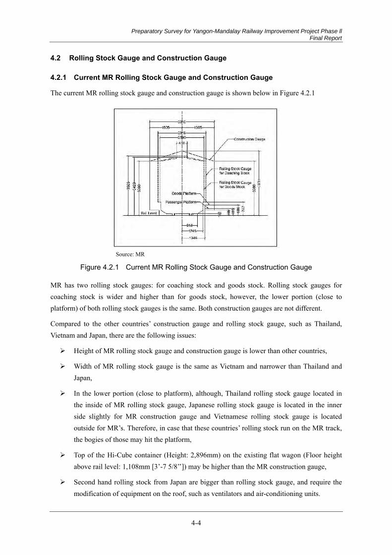
Preparatory Survey for Yangon-Mandalay Railway Improvement Project Phase ll Final Report
4-4
4.2 Rolling Stock Gauge and Construction Gauge
Current MR Rolling Stock Gauge and Construction Gauge 4.2.1
The current MR rolling stock gauge and construction gauge is shown below in Figure 4.2.1
Source: MR
Figure 4.2.1 Current MR Rolling Stock Gauge and Construction Gauge
MR has two rolling stock gauges: for coaching stock and goods stock. Rolling stock gauges for coaching stock is wider and higher than for goods stock, however, the lower portion (close to platform) of both rolling stock gauges is the same. Both construction gauges are not different.
Compared to the other countries’ construction gauge and rolling stock gauge, such as Thailand, Vietnam and Japan, there are the following issues:
Height of MR rolling stock gauge and construction gauge is lower than other countries,
Width of MR rolling stock gauge is the same as Vietnam and narrower than Thailand and Japan,
In the lower portion (close to platform), although, Thailand rolling stock gauge located in the inside of MR rolling stock gauge, Japanese rolling stock gauge is located in the inner side slightly for MR construction gauge and Vietnamese rolling stock gauge is located outside for MR’s. Therefore, in case that these countries’ rolling stock run on the MR track, the bogies of those may hit the platform,
Top of the Hi-Cube container (Height: 2,896mm) on the existing flat wagon (Floor height above rail level: 1,108mm [3’-7 5/8’’]) may be higher than the MR construction gauge,
Second hand rolling stock from Japan are bigger than rolling stock gauge, and require the modification of equipment on the roof, such as ventilators and air-conditioning units.
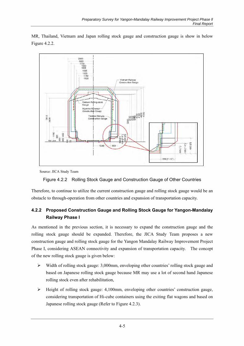
Preparatory Survey for Yangon-Mandalay Railway Improvement Project Phase ll Final Report
4-5
MR, Thailand, Vietnam and Japan rolling stock gauge and construction gauge is show in below Figure 4.2.2.
Source: JICA Study Team
Figure 4.2.2 Rolling Stock Gauge and Construction Gauge of Other Countries
Therefore, to continue to utilize the current construction gauge and rolling stock gauge would be an obstacle to through-operation from other countries and expansion of transportation capacity.
Proposed Construction Gauge and Rolling Stock Gauge for Yangon-Mandalay 4.2.2Railway Phase I
As mentioned in the previous section, it is necessary to expand the construction gauge and the rolling stock gauge should be expanded. Therefore, the JICA Study Team proposes a new construction gauge and rolling stock gauge for the Yangon Mandalay Railway Improvement Project Phase I, considering ASEAN connectivity and expansion of transportation capacity. The concept of the new rolling stock gauge is given below:
Width of rolling stock gauge: 3,000mm, enveloping other countries’ rolling stock gauge and based on Japanese rolling stock gauge because MR may use a lot of second hand Japanese rolling stock even after rehabilitation,
Height of rolling stock gauge: 4,100mm, enveloping other countries’ construction gauge, considering transportation of Hi-cube containers using the exiting flat wagons and based on Japanese rolling stock gauge (Refer to Figure 4.2.3).
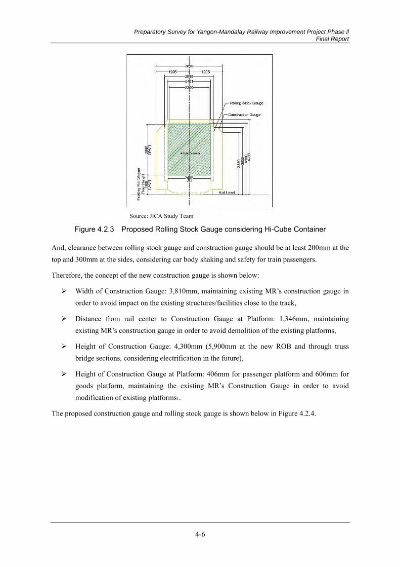
Preparatory Survey for Yangon-Mandalay Railway Improvement Project Phase ll Final Report
4-6
Source: JICA Study Team
Figure 4.2.3 Proposed Rolling Stock Gauge considering Hi-Cube Container
And, clearance between rolling stock gauge and construction gauge should be at least 200mm at the top and 300mm at the sides, considering car body shaking and safety for train passengers.
Therefore, the concept of the new construction gauge is shown below:
Width of Construction Gauge: 3,810mm, maintaining existing MR’s construction gauge in order to avoid impact on the existing structures/facilities close to the track,
Distance from rail center to Construction Gauge at Platform: 1,346mm, maintaining existing MR’s construction gauge in order to avoid demolition of the existing platforms,
Height of Construction Gauge: 4,300mm (5,900mm at the new ROB and through truss bridge sections, considering electrification in the future),
Height of Construction Gauge at Platform: 406mm for passenger platform and 606mm for goods platform, maintaining the existing MR’s Construction Gauge in order to avoid modification of existing platforms1.
The proposed construction gauge and rolling stock gauge is shown below in Figure 4.2.4.
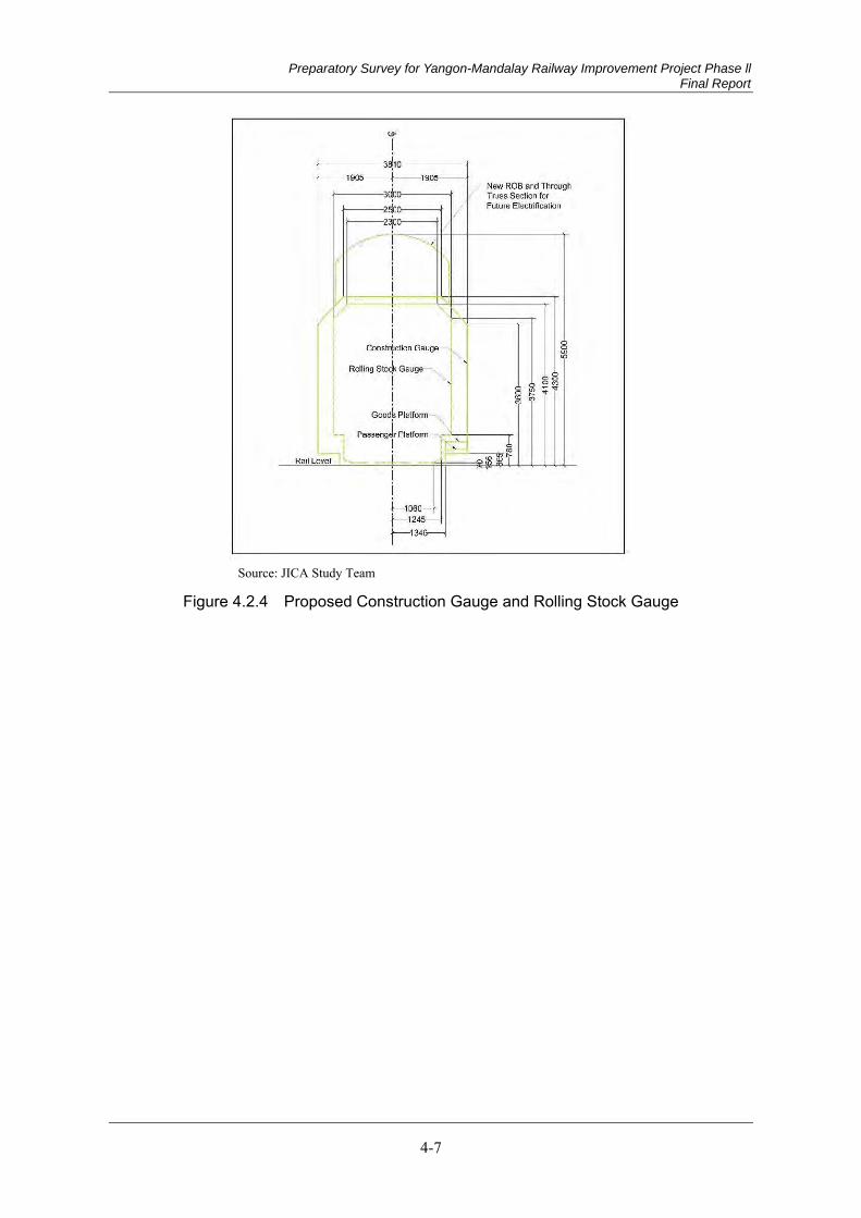
Preparatory Survey for Yangon-Mandalay Railway Improvement Project Phase ll Final Report
4-7
Source: JICA Study Team
Figure 4.2.4 Proposed Construction Gauge and Rolling Stock Gauge

Preparatory Survey for Yangon-Mandalay Railway Improvement Project Phase ll Final Report
4-8
4.3 Axel Load of Train
Current MR Axle Load 4.3.1
Regarding axle load for the existing bridge design in the Yangon Mandalay Railway, 17 t of H.M.(Heavy Mineral: maximum load 17.0t) or M.L. (Main Line: maximum load 13.0t) are applied. Standard loading is shown in the following page.
Source:MR
Figure 4.3.1 MR’s Standard Loading (H.M. and M.L.)
Proposed MR Axel Load of Train for Yangon-Mandalay Railway 4.3.2
Considering introduction of new DEMU and ASEAN connectivity, the JICA Study Team proposes the following axle loads:
New DEMU: 12.5 t Axle load
UIC standard: 200 kN Axle Load, considering ASEAN connectivity
The proposed axle load of train is shown below in Figure 4.3.2.
Source: JICA Study Team
Figure 4.3.2 Proposed Axle Load of Train
UIC 200kN axle load shall be applied to design the new bridge, track and civil structures.
Preparatory Survey for Yangon-Mandalay Railway Improvement Project Phase ll Final Report
5-1
Chapter 5 Railway Project Plan
5.1 Train Operation
As is stated in Chapter 1, the goal of this railway improvement project is to achieve 100km/h speed train operation on the existing railway between Yangon and Mandalay by improving and modernizing its decrepit infrastructure and facilities and thereby to realize 8-hour travel time between the two biggest cities. In Phase 1, the travel time between Yangon Central Station and Taungoo Station of 267 km was estimated 3 hours and 9 minutes by the fastest train as a result of simulation. The travel time between Taungoo Station and Mandalay Station will be estimated in the detail design stage after the track layout is designed. Considering the distance of Phase 1 and that of Phase 2, it is likely that the travel time between Yangon and Mandalay will be within 8 hours.
The purposes of this chapter are
To show the future plan of train operation,
To demonstrate the draft DEMU operation plan and thereby to provide the preconditions to develop the depot plan, and
To show the draft station track layout which can realize the 8 hour travel time and thereby to provide the preconditions to develop the civil and signalling plans.
Current Conditions of Train Operation 5.1.1
Among various current situations, the issues related with the modernization of train operation, especially high speed operation and high frequency operation, are stated below.
Maximum Speed (1)
According to an old document called “Working Time Book” edited on 1st August, 1962 by Burma Railways, the maximum speed was 64 km/h throughout the section at that time. However, due to the lack of maintenance on tracks and the age related deterioration of infrastructure, current maximum speed is less than 64 km/h for some sections. Table 5.1.1 shows the list of maximum speed for each section.
Preparatory Survey for Yangon-Mandalay Railway Improvement Project Phase ll Final Report
5-2
Table 5.1.1 Maximum Speed on the Main Line
Section Maximum Speed (km/h)
Cause of Restriction Up Dn
Taungoo - Thargaya 56 56 Unstable embankment Thargaya – Yeni 67 67 Yeni - Pyinmana 64 64 Pyinmana - Ywadaw 64 64 Ywadaw - Kyidaungkan 48 48 Unstable embankment Kyidaungkan - Shwemyo 64 64 Shwemyo - Sinthe 64 48 Unstable embankment Sinthe - Tatkon 64 48 Ditto Tatkon - Magyibin 64 48 Ditto Magyibin - Nyaunglun 64 48 Ditto Nyaunglun - Yamethin 64 48 Ditto Yamethin - Ingyinkan 69 48 Ditto Ingyinkan - Shweda 69 48 Ditto Shweda - Pyawbwe 48 48 Ditto Pyawbwe - Shanywa 48 69 Ditto Shanywa - Nyaungyan 56 69 Ditto Nyaungyan - Nwato 56 69 Ditto Nwato - Thazi 64 69 Ditto Thazi - Ywapale 64 69 Ditto Ywapale - Hanza 64 64 Hanza - Thedaw 69 69 Thedaw - Samon 69 69 Samon – Kume Lan 64 64 Kume Lan - Myohaung 69 69 Myohaung - Mandalay 48 48 Public safety
Speed Restriction by Gradient and at Curves (2)
As the line between Yangon and Mandalay is laid in flat areas, there is no speed restriction on slopes. Also, when trains run based on the maximum speed prescribed in (1), there is no speed restriction in curves, but 100km/h operation in the future will require speed restrictions in the curves.
Speed Restriction in Stations (3)
Speed limits are prescribed for each station according to various conditions, such as types of points including its locking system, distance allowance for overrun, the isolation of sidings from main lines by approved means of isolation including trap points. According to the prescription by MR, passing trains have to reduce speed to 40 - 50km/h at many stations.

Preparatory Survey for Yangon-Mandalay Railway Improvement Project Phase ll Final Report
5-3
In main stations including Pyinmana Station, Thazi Station and Mandalay Station, speed is restricted to 32 km/h (16 km/h in Mandalay Station), due to the poor locking system of facing points.
Block System and Block Stations (4)
The Absolute Block System is applied to the section between Taungoo Station and Mandalay Station. This system is to secure the safety in which only one train is occupied in the block between two adjacent stations to prevent a collision accident.
A train driver needs a notice called an Authority to Proceed by the station master when leaving a block station. This system is called a Paper Line Clear in MR. When a train passes a block station, a station staff gives the notice by using a special tool made of bamboo as shown in Figure 5.1.1. This work would be impossible in 100km/h operation in the future.
Among the 55 stations in Phase 2, the following 7 stations are halt stations (non-block stations). Some trains stop at the designated place without platform where passengers get on and off.
Kaytumadi
Tharyargon
Hteininn
Dahattaw
Khinban
Odokkon
Shanzu
At Shanzu Station, 7 trains stop every day and the average number of passengers getting on is 29 per day. Except Khinban Station where 17 passengers get on every day on average, almost no passengers use the other stations.
Level Crossing (5)
Some particular issues are stated here that would affect the modernization of train operation.
Firstly, in many cases, to recognize an approaching train and thereafter to close the gates are undertaken by a gateman at the direction of the station master through a phone or by his visual observation without any systematic support. As the line is modernized, the interval will be shortened from the time when he acknowledges an approaching train to the time when it reaches the level crossing as the result of the 100km/h operation. Also, the train frequency is likely to be
Source: JICA Study Team
Figure 5.1.1 Receiving of Authority to Proceed at Kyauktaga Station (Phase 1)
Preparatory Survey for Yangon-Mandalay Railway Improvement Project Phase ll Final Report
5-4
increased. These factors will not only increase the burden on the gatemen but also cause an emergency stop of a train or, in the worst case, a level crossing accident due to the delay of the gateman’s operation.
Secondly, at many level crossings, the Proceed signal is given to a train driver by a gateman by using his green flag or by his green light at night after he closes the gates and secures the safety in the level crossing. As the interval is shortened from the time when a train driver recognizes the green flag to the time when the train reaches the level crossing in the future 100km/h operation, the train driver’s visibility as well as safety for gatemen themselves shall be taken into consideration.
Shunting in a Station (6)
When a fast train passes a slow train or some vehicles are stabled at a station, a loop line is utilized in some cases, but in other cases MR uses a siding called “Lay Bye” as is shown in Figure 5.1.2. The “Lay Bye” is effective to improve safety by not using facing points for main line operation and thus to minimize the speed reduction of a passing train. On the other hand, passing of a slower train by a faster train or stabling of vehicles is performed by shunting on main lines. This could be possible only when train speed and frequency are low like today.
If one of the two lines, Up and Down lines, is blocked for some reasons such as accident and disaster, MR sometimes operates both Up trains and Down trains on the other available line. In this case, a train has to cross between the Up line and Down line at a station. In order to avoid facing points in normal operation, the track layout of the crossover between the two lines is as shown in Figure 5.1.2. This case also requires the shunting on main lines.
Source: JICA Study Team
Figure 5.1.2 Example of Lay Bye and Crossover (Tawa Station: Phase 1)
Automatic Train Protection System (7)
MR has never introduced a backup system for train drivers to avoid a SPAD (Signal Passed At Danger). This safety issue is dependent only on the caution of drivers and assistant drivers.

Preparatory Survey for Yangon-Mandalay Railway Improvement Project Phase ll Final Report
5-5
Traffic Management (8)
All the important decisions regarding traffic management are made by the Operation Control Center (OCC) in the MR Headquarters, such as the cancellation of a train service, temporary stop of a train at a station, and the recovery plan in case of accidents and traffic disturbances. The OCC in the Headquarters sends commands to the OCC of each division, and each OCC sends commands to the related station masters in its division directing them to execute the necessary operation.
Although these OCCs don’t capture information regarding the location of each train on time, an ongoing Grant Aid by JICA, “the Project for Installation of Operation Control Center System and Safety Equipment (OCC Project)”, will provide a centralized train monitoring system between Yangon and Pyuntaza by the end of Phase 1 of this project.
These OCCs and the stations between Yangon and Taungoo can communicate with each other through cable and radio telecommunication. On the other hand, train operation is basically based on the signals of each station. When a special command to a train driver is required, it is delivered from the station master as a paper notice. There exists no means of radio communication to train drivers from OCCs or station masters.
Passenger Transport (9)
Regarding the current express trains on Yangon Mandalay Line, there are 3 round trips between Yangon and Mandalay and 2 round trips between Yangon and Naypyitaw every day. All the trains are the coach train pulled by a diesel electric locomotive (DEL). For some services, a train composing of a new Chinese DEL and new Chinese coaches started operation in 2016 (Figure 5.1.4). Table 5.1.2 shows the travel time of the current express trains between Yangon and Mandalay.
Table 5.1.3 shows the current local trains on Yangon Mandalay Line.
There are other trains operated on Yangon Mandalay Line departing and arriving at Naypyitaw Station going into a branch line at a station on Yangon Mandalay Line.
Source: JICA Study Team
Figure 5.1.3 Taungoo OCC
Source: JICA Study Team
Figure 5.1.4 Express Train by new Chinese DEL and Coaches
Preparatory Survey for Yangon-Mandalay Railway Improvement Project Phase ll Final Report
5-6
Table 5.1.2 Travel Time of Current Express Trains (Yangon - Mandalay)
Train Number Travel Time 3 UP, 4 DN (Night train) 14 hours 45 minutes 5 UP, 6 DN (Night train) 14 hours 00 minutes 11 UP, 12 DN (Day train) 14 hours 50 minutes
Source: JICA Study Team
Table 5.1.3 Local Trains (between Taungoo and Mandalay)
Origin & Destination Number of Services Yangon - Mandalay (Mail Train) 1 round trip Yangon - Thazi (Main Train) 1 round trip Taungoo - Thazi 1 round trip (every 2 days) Thazi - Myohaung 1 round trip Pyinmana - Tatkon 2 round trips
Source: JICA Study Team
Freight Transport (10)
Any freight train does not have a timetable. The departure time at the origin station is decided when the freight train has been set up after loading and the OCC finds an adequate time between passenger trains. After leaving the origin station, the freight train travels as far as the operation does not disturb passenger trains. When a passenger train approaches to the freight train from behind, the freight train has to wait for the approaching train at a station on the way.
Currently 2 to 5 round trips of freight trains are daily operated between Mahlwagon Station and Myohaung Station. Also, some wagons are connected with local trains described in (9).
Future Plan of Train Operation 5.1.2
Maximum Speed (1)
As is mentioned in Chapter 1, the maximum speed of the line will be set 100km/h for the whole main line.
Speed Restriction (2)
As the section between Taungoo and Mandalay is flat, there will be no speed restriction by slope. In case the speed restriction by curve is inevitable due to topographical conditions, the track layout should be taken care of in such a way that the curve will not affect the travel time as much as possible.
Speed Restriction in Stations (3)
For each station, necessary measures including the interlocking of signals and points and safety sidings should be taken so that trains can pass the station without reducing its speed. However, in
Preparatory Survey for Yangon-Mandalay Railway Improvement Project Phase ll Final Report
5-7
the large scale of stations, namely Pyinmana Station, Thazi Station and Mandalay Station, to set safety sidings will shorten the effective length of lines and thus the JICA Study Team proposes not to set safety sidings in these stations and to remain the speed restriction as it is.
Block System and Block Stations (4)
The Absolute Block System will be adopted between Taungoo and Mandalay as it is today. The current method “Paper Line Clear” shall not be used but the train driver shall secure the block to the next station by the Proceed aspect of the Starter signal.
Among the 7 halt stations, the 5 stations where almost no passengers use are expected to be abolished so that the travel time on that block section will be shorter and the line capacity will not become smaller. Khinban Station located between Thedaw Station and Samon Station is expected to remain as a station. In order not to increase the travel time between Thedaw Station and Samon Station and to keep enough line capacity in the future, the JICA Study Team proposes that Khinban Station become a block station. This means that the current block between Thedaw Station and Samon Station will be divided into 2 block sections.
Shanzu Station is also expected to remain a station for passengers. Considering that the distance between Myohaung Station and Mandalay Station is rather short, the JICA Study Team proposes that the Automatic Block System be installed between Myohaung Station and Mandalay Station instead of the Absolute Block System and that Shanzu Station remain as a halt station as it is. This modification is expected to require less cost compared with the case that Shanzu Station becomes a block station, while the line capacity is almost the same for the two cases.
Level Crossing (5)
To keep the safety for the 100 km/h operation, the level crossings inside stations and those located between the Distant signal and the Outer signal are expected to be equipped with level crossing safety equipment as is the same as the design in Detailed Design for Yangon-Mandalay Railway Improvement Project Phase I (YM-D/D(1)). Even for the level crossings between stations, the JICA Study Team will consider to install the level crossing safety equipment on them if power supply is available. For the purpose of preventing level crossing accidents, the gatemen of all the official level crossings whether or not they are equipped with the safety equipment are to use a portable radio device so that they can get train approaching information from nearby station masters. Details are stated in Section 5.12.
According to the General Rules of MR, gatemen are supposed to show the Proceed signal by hand or by light after confirming that the gate has been closed and the train driver must stop before the level crossing if he cannot recognizes the Proceed signal. For most of the level crossings which are not to be equipped with the level crossing safety equipment, the train driver can recognize the signal even in the 100 km/h operation as they are located in a long straight section. Before MR
Preparatory Survey for Yangon-Mandalay Railway Improvement Project Phase ll Final Report
5-8
starts 100km/h operation, however, MR should educate train drivers concerning this rule again by taking necessary measures such as reducing speed since 100 km/h operation might reduce visibility.
Shunting in a Station (6)
Current lay bye lines are expected to be abolished in principle.
Automatic Train Protection System (7)
As is the same as Phase 1, the signals where train driver’s human errors might cause serious accidents are expected to be equipped with the Automatic Train Protection System. The specifications should be the same as those of Phase 1 so that the on-board equipment installed in Phase 1 is able to be used for the Phase 2 section.
Traffic Management (8)
While the OCC Project will install the Operation Control Center System for the section between Yangon Central Station and Pyuntaza Station, the rest of the whole section of Yangon Mandalay Line, including the Phase 1 section between Nyaung le bin Station and Taungoo Station, is expected to be covered by an Operation Control Center System.
As the current radio telecommunication system is improved in this project, train drivers, level crossing gatemen and maintenance staff are expected to communicate with station masters and OCC through a portable radio device in order to contribute to the safety and stable train operation.
Passenger Transport (9)
As was planned in Phase 1, a plenty of DEMU cars are to be installed for express trains of Yangon Mandalay Line and also some local type of DEMU cars are to be installed for local trains between Yangon Central Station and Bago Station.
Regarding the local trains on the sections north from Bago Station, locomotive hauled coach trains will be operated as today. These vehicles are out of scope of this project.
Freight Transport (10)
Regarding the freight transport, container transport is expected to increase in the future. As is stated in 5.15, however, MR has launched a Public Private Partnership (PPP) project for container transport with industrial and domestic transport companies. In this regard, the container transport is out of scope of this project. However, the track layout of the related stations should be designed in such a way that container trains will be able to go into and go out of the dry port by the PPP project. Under the PPP project, new dry ports are being constructed at Myitnge Station. The detail information regarding this PPP project is stated in 5.15.2 (3) 2).
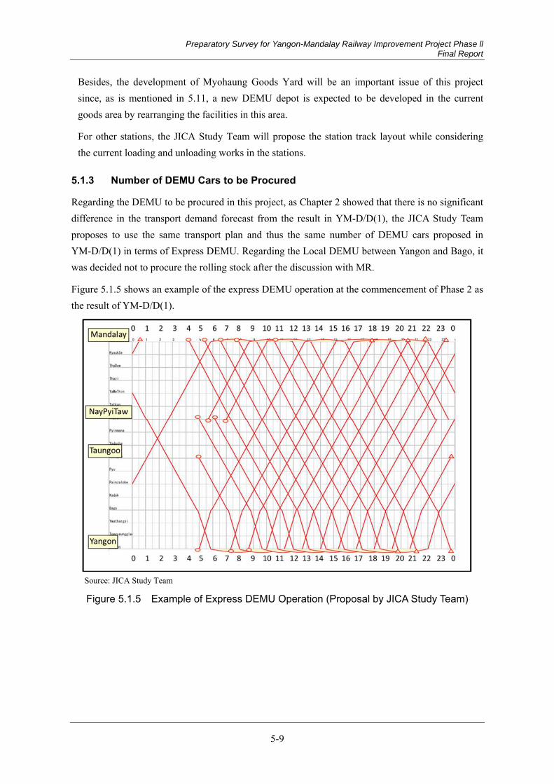
Preparatory Survey for Yangon-Mandalay Railway Improvement Project Phase ll Final Report
5-9
Besides, the development of Myohaung Goods Yard will be an important issue of this project since, as is mentioned in 5.11, a new DEMU depot is expected to be developed in the current goods area by rearranging the facilities in this area.
For other stations, the JICA Study Team will propose the station track layout while considering the current loading and unloading works in the stations.
Number of DEMU Cars to be Procured 5.1.3
Regarding the DEMU to be procured in this project, as Chapter 2 showed that there is no significant difference in the transport demand forecast from the result in YM-D/D(1), the JICA Study Team proposes to use the same transport plan and thus the same number of DEMU cars proposed in YM-D/D(1) in terms of Express DEMU. Regarding the Local DEMU between Yangon and Bago, it was decided not to procure the rolling stock after the discussion with MR.
Figure 5.1.5 shows an example of the express DEMU operation at the commencement of Phase 2 as the result of YM-D/D(1).
Source: JICA Study Team
Figure 5.1.5 Example of Express DEMU Operation (Proposal by JICA Study Team)
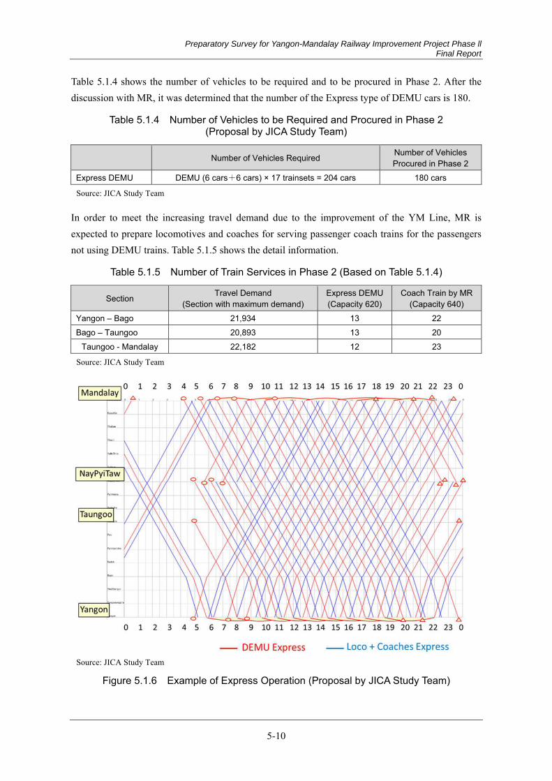
Preparatory Survey for Yangon-Mandalay Railway Improvement Project Phase ll Final Report
5-10
Table 5.1.4 shows the number of vehicles to be required and to be procured in Phase 2. After the discussion with MR, it was determined that the number of the Express type of DEMU cars is 180.
Table 5.1.4 Number of Vehicles to be Required and Procured in Phase 2 (Proposal by JICA Study Team)
Number of Vehicles Required Number of Vehicles Procured in Phase 2
Express DEMU DEMU (6 cars+6 cars) × 17 trainsets = 204 cars 180 cars
Source: JICA Study Team
In order to meet the increasing travel demand due to the improvement of the YM Line, MR is expected to prepare locomotives and coaches for serving passenger coach trains for the passengers not using DEMU trains. Table 5.1.5 shows the detail information.
Table 5.1.5 Number of Train Services in Phase 2 (Based on Table 5.1.4)
Section Travel Demand (Section with maximum demand)
Express DEMU (Capacity 620)
Coach Train by MR (Capacity 640)
Yangon – Bago 21,934 13 22 Bago – Taungoo 20,893 13 20
Taungoo - Mandalay 22,182 12 23
Source: JICA Study Team
Source: JICA Study Team
Figure 5.1.6 Example of Express Operation (Proposal by JICA Study Team)
Preparatory Survey for Yangon-Mandalay Railway Improvement Project Phase ll Final Report
5-11
Table 5.1.5 shows the number of DEMU trains and the number of coach trains to be provided by MR. The decision how many express coach trains should be set and how many local coach trains should be set will be made by MR. Suppose that the number of express coach trains is the same as DEMU, 13 trains, the draft express operation plan is demonstrated in Figure 5.1.6.
Other than these express trains, low speed trains such as local trains and freight trains are to be operated. The express trains will have to pass these low speed trains at stations. In the coming detailed design stage, it will be necessary to examine whether the operation plan is feasible or not by the station track layout plan stated in 5.1.4 below.
Draft Station Track Layout 5.1.4
It is necessary to decide the station track layout considering the two points below, while following the various rules of MR.
Line Capacity
When there are various types of trains with different speed, there need stations where a fast train passes a slow train. On the other hand, if there are many stations with such a function, expensive facilities including turnouts and complex interlocking systems are required and thus the total project cost will be higher.
Works at Stations including Shunting Works
Current loading and unloading works of freight trains including ballast transport and other types of works at each station should be taken into consideration. Also, MR’s future plans for freight transport should be considered, if any.
The JICA Study Team visited all the stations to make a survey with the support by MR in this study. The JICA Study Team interviewed the station master about the current works of each station. The JICA Study Team developed the draft track layout plan of each station, taking the opinions of the station master and a traffic manager of MR into consideration. Attachment 5-1 shows the draft station layouts the JICA Study Team proposes. The outline of the proposal is summarized as follows.
The track layouts could be classified into the following three types.
(1) Up and Down main lines only
(2) Up and Down main lines with a few loop lines
(3) Up and Down main lines with lots of loop lines and/or stabling lines
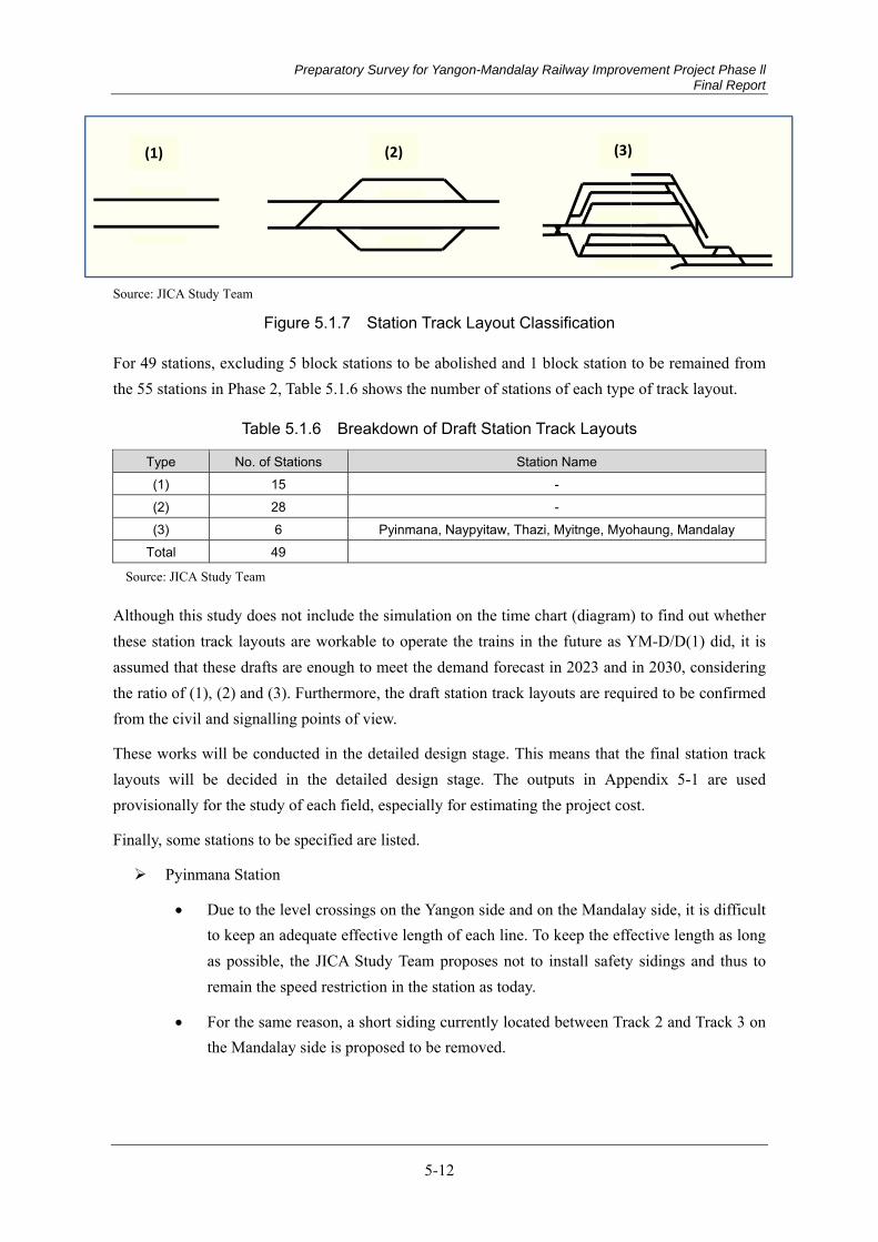
Preparatory Survey for Yangon-Mandalay Railway Improvement Project Phase ll Final Report
5-12
Source: JICA Study Team
Figure 5.1.7 Station Track Layout Classification
For 49 stations, excluding 5 block stations to be abolished and 1 block station to be remained from the 55 stations in Phase 2, Table 5.1.6 shows the number of stations of each type of track layout.
Table 5.1.6 Breakdown of Draft Station Track Layouts
Type No. of Stations Station Name (1) 15 - (2) 28 - (3) 6 Pyinmana, Naypyitaw, Thazi, Myitnge, Myohaung, Mandalay
Total 49
Source: JICA Study Team
Although this study does not include the simulation on the time chart (diagram) to find out whether these station track layouts are workable to operate the trains in the future as YM-D/D(1) did, it is assumed that these drafts are enough to meet the demand forecast in 2023 and in 2030, considering the ratio of (1), (2) and (3). Furthermore, the draft station track layouts are required to be confirmed from the civil and signalling points of view.
These works will be conducted in the detailed design stage. This means that the final station track layouts will be decided in the detailed design stage. The outputs in Appendix 5-1 are used provisionally for the study of each field, especially for estimating the project cost.
Finally, some stations to be specified are listed.
Pyinmana Station
Due to the level crossings on the Yangon side and on the Mandalay side, it is difficult to keep an adequate effective length of each line. To keep the effective length as long as possible, the JICA Study Team proposes not to install safety sidings and thus to remain the speed restriction in the station as today.
For the same reason, a short siding currently located between Track 2 and Track 3 on the Mandalay side is proposed to be removed.
(1) (2) (3)
Preparatory Survey for Yangon-Mandalay Railway Improvement Project Phase ll Final Report
5-13
Ywadaw Station
Ywadaw Station will be the freight terminal in the Naypyitaw area. Details are stated in 5.15.3 (1).
Sinthe Station
The facilities in the station for the branch line to Pinlaung Station (Division 4) are to be removed.
Pyawbwe Station
The branch line to Lintsinkon Station is to be remained.
Thazi Station
There are two tracks to the branch line to Myingyan Station, the track previously used and the track currently used. In this project, the track previously used, which is located on the Yangon side, is to be remained and the track currently used is to be removed.
Five (5) stabling lines are to be removed to install freight facilities. Details are stated in 5.15.3 (1).
Ywapale Station and Hanza Station
A water tank wagon is stabled for the station staff in the lay bye line in front of the station building since this area is lack of water. The JICA Study Team proposes to quit this service and then to remove these lay bye lines.
Myitnge Station
The level crossing next to the platform going to Myitnge Workshop is to be removed and construct an overpass instead.
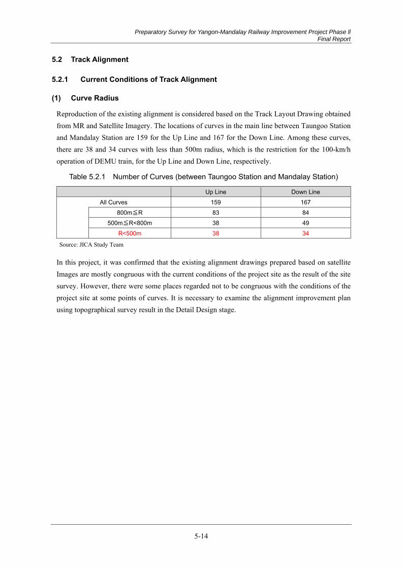
Preparatory Survey for Yangon-Mandalay Railway Improvement Project Phase ll Final Report
5-14
5.2 Track Alignment
Current Conditions of Track Alignment 5.2.1
Curve Radius (1)
Reproduction of the existing alignment is considered based on the Track Layout Drawing obtained from MR and Satellite Imagery. The locations of curves in the main line between Taungoo Station and Mandalay Station are 159 for the Up Line and 167 for the Down Line. Among these curves, there are 38 and 34 curves with less than 500m radius, which is the restriction for the 100-km/h operation of DEMU train, for the Up Line and Down Line, respectively.
Table 5.2.1 Number of Curves (between Taungoo Station and Mandalay Station)
Up Line Down Line All Curves 159 167
800m≦R 83 84
500m≦R<800m 38 49 R<500m 38 34
Source: JICA Study Team
In this project, it was confirmed that the existing alignment drawings prepared based on satellite Images are mostly congruous with the current conditions of the project site as the result of the site survey. However, there were some places regarded not to be congruous with the conditions of the project site at some points of curves. It is necessary to examine the alignment improvement plan using topographical survey result in the Detail Design stage.
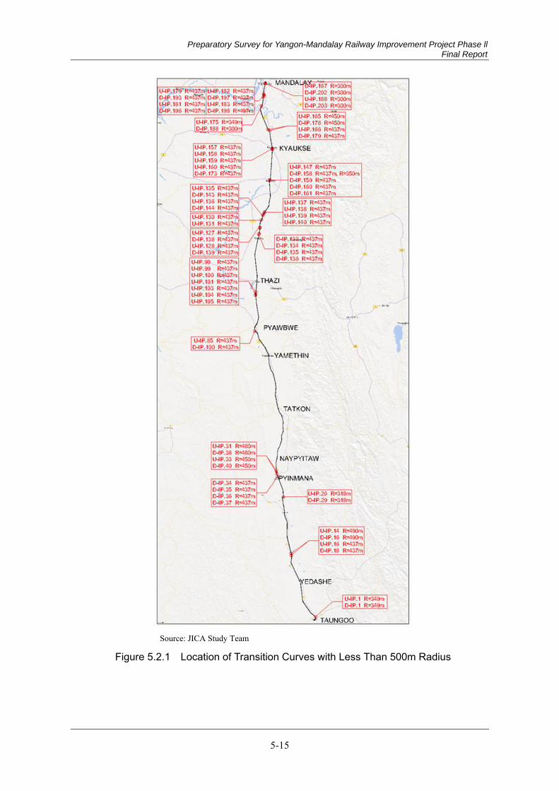
Preparatory Survey for Yangon-Mandalay Railway Improvement Project Phase ll Final Report
5-15
Source: JICA Study Team
Figure 5.2.1 Location of Transition Curves with Less Than 500m Radius

Preparatory Survey for Yangon-Mandalay Railway Improvement Project Phase ll Final Report
5-16
Although transition curve is not described in the Track Layout Drawing, JST was able to confirm the Curve Ledger possessed by the track maintenance division, from the MR staff accompanying the site survey. According to this, it is found out that transition curve is inserted in the existing line. Since there is no description regarding transition curve length in this Curve Ledger, it is unclear what length of transition curve is inserted with each curve. However, the design maximum speed is indicated to be 45 mph (= approximately 72.4 km/h) in the MR construction regulation (Burma Railways Manual of the Engineering Department). Therefore, it is expected that the transition curve length corresponding to this speed is inserted.
In any case, in order to operate at 100 km/h, extension of the transition curve corresponding to this speed is needed.
Source: JICA Study Team
Figure 5.2.2 Curve Ledger possessed by the track maintenance division
Gradient (2)
According to the Track Layout Drawing, vertical alignment is smooth through the whole line, and the maximum gradient is 6‰. Gradient will be examined carefully through the site survey result.
Recommendation for Track Alignment 5.2.2
Design Standard for Track Alignment (1)
The speed limit on curve is decided by gauge and vehicle performance. For the DEMU and passenger trains, the relation between curve radius and speed limit is shown in Table 5.2.2. For the 100 km/h operation of DEMU train, the curve radius of 500 m or more is needed. On the other hand, for the 100 km/h operation of limited express passenger train, the curve radius of 800 m or more is needed.
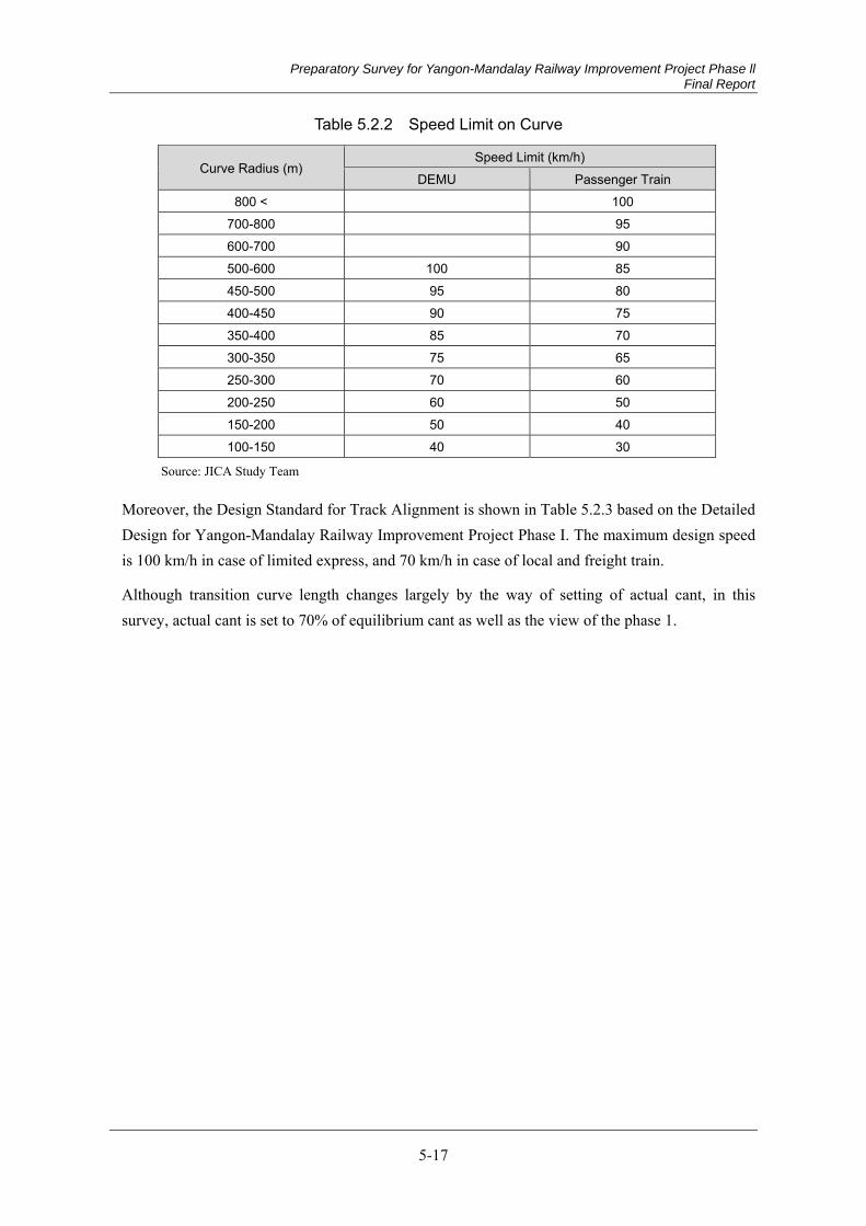
Preparatory Survey for Yangon-Mandalay Railway Improvement Project Phase ll Final Report
5-17
Table 5.2.2 Speed Limit on Curve
Curve Radius (m) Speed Limit (km/h)
DEMU Passenger Train 800 < 100
700-800 95 600-700 90 500-600 100 85 450-500 95 80 400-450 90 75 350-400 85 70 300-350 75 65 250-300 70 60 200-250 60 50 150-200 50 40 100-150 40 30
Source: JICA Study Team
Moreover, the Design Standard for Track Alignment is shown in Table 5.2.3 based on the Detailed Design for Yangon-Mandalay Railway Improvement Project Phase I. The maximum design speed is 100 km/h in case of limited express, and 70 km/h in case of local and freight train.
Although transition curve length changes largely by the way of setting of actual cant, in this survey, actual cant is set to 70% of equilibrium cant as well as the view of the phase 1.
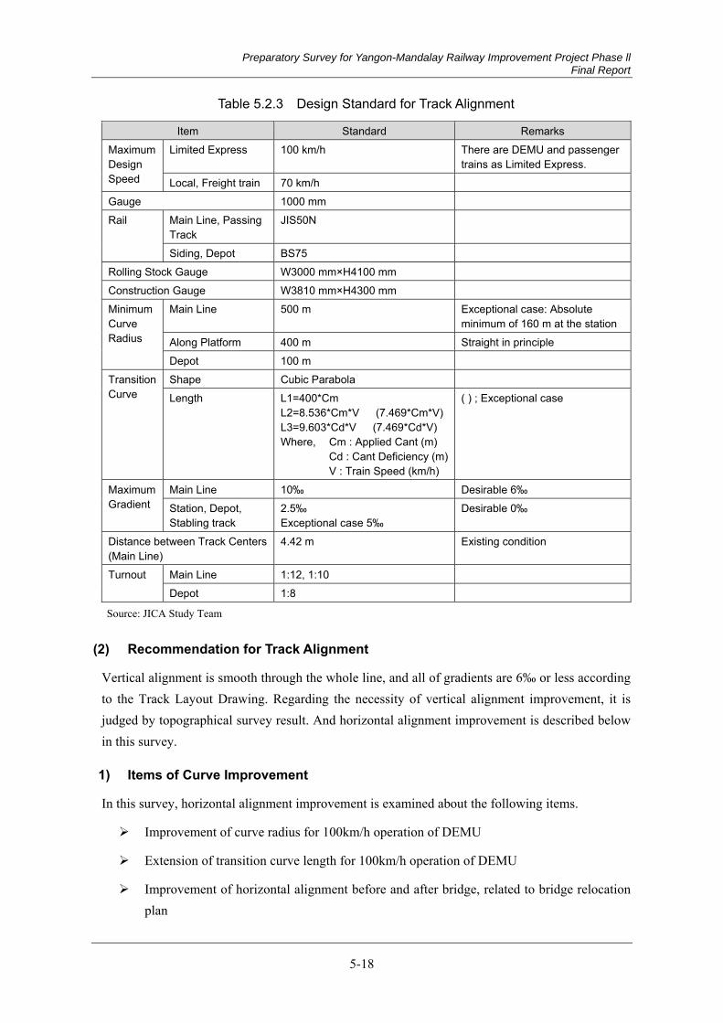
Preparatory Survey for Yangon-Mandalay Railway Improvement Project Phase ll Final Report
5-18
Table 5.2.3 Design Standard for Track Alignment
Item Standard Remarks Maximum Design Speed
Limited Express 100 km/h There are DEMU and passenger trains as Limited Express.
Local, Freight train 70 km/h Gauge 1000 mm Rail Main Line, Passing
Track JIS50N
Siding, Depot BS75 Rolling Stock Gauge W3000 mm×H4100 mm Construction Gauge W3810 mm×H4300 mm Minimum Curve Radius
Main Line 500 m Exceptional case: Absolute minimum of 160 m at the station
Along Platform 400 m Straight in principle Depot 100 m
Transition Curve
Shape Cubic Parabola Length L1=400*Cm
L2=8.536*Cm*V (7.469*Cm*V) L3=9.603*Cd*V (7.469*Cd*V) Where, Cm : Applied Cant (m) Cd : Cant Deficiency (m) V : Train Speed (km/h)
( ) ; Exceptional case
Maximum Gradient
Main Line 10‰ Desirable 6‰ Station, Depot, Stabling track
2.5‰ Exceptional case 5‰
Desirable 0‰
Distance between Track Centers (Main Line)
4.42 m Existing condition
Turnout Main Line 1:12, 1:10 Depot 1:8
Source: JICA Study Team
Recommendation for Track Alignment (2)
Vertical alignment is smooth through the whole line, and all of gradients are 6‰ or less according to the Track Layout Drawing. Regarding the necessity of vertical alignment improvement, it is judged by topographical survey result. And horizontal alignment improvement is described below in this survey.
1) Items of Curve Improvement
In this survey, horizontal alignment improvement is examined about the following items.
Improvement of curve radius for 100km/h operation of DEMU
Extension of transition curve length for 100km/h operation of DEMU
Improvement of horizontal alignment before and after bridge, related to bridge relocation plan
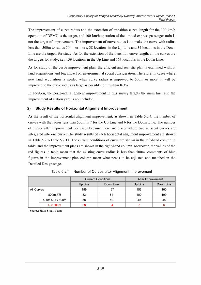
Preparatory Survey for Yangon-Mandalay Railway Improvement Project Phase ll Final Report
5-19
The improvement of curve radius and the extension of transition curve length for the 100-km/h operation of DEMU is the target, and 100-km/h operation of the limited express passenger train is not the target of improvement. The improvement of curve radius is to make the curve with radius less than 500m to radius 500m or more, 38 locations in the Up Line and 34 locations in the Down Line are the targets for study. As for the extension of the transition curve length, all the curves are the targets for study, i.e., 159 locations in the Up Line and 167 locations in the Down Line.
As for study of the curve improvement plan, the efficient and realistic plan is examined without land acquisitions and big impact on environmental social consideration. Therefore, in cases where new land acquisition is needed when curve radius is improved to 500m or more, it will be improved to the curve radius as large as possible to fit within ROW.
In addition, the horizontal alignment improvement in this survey targets the main line, and the improvement of station yard is not included.
2) Study Results of Horizontal Alignment Improvement
As the result of the horizontal alignment improvement, as shown in Table 5.2.4, the number of curves with the radius less than 500m is 7 for the Up Line and 6 for the Down Line. The number of curves after improvement decreases because there are places where two adjacent curves are integrated into one curve. The study results of each horizontal alignment improvement are shown in Table 5.2.5-Table 5.2.11. The current conditions of curve are shown in the left-hand column in table, and the improvement plans are shown in the right-hand column. Moreover, the values of the red figures in table mean that the existing curve radius is less than 500m, comments of blue figures in the improvement plan column mean what needs to be adjusted and matched in the Detailed Design stage.
Table 5.2.4 Number of Curves after Alignment Improvement
Current Conditions After Improvement
Up Line Down Line Up Line Down Line All Curves 159 167 156 160
800m≦R 83 84 100 109
500m≦R<800m 38 49 49 45 R<500m 38 34 7 6
Source: JICA Study Team
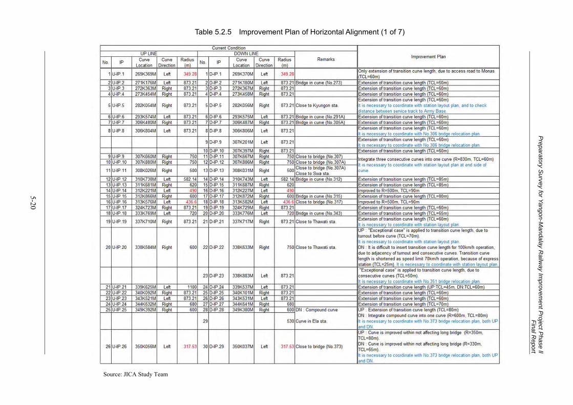
Preparatory S
urvey for Yangon-Mandalay R
ailway Im
provement P
roject Phase ll
Final Report
5-20
Table 5.2.5 Improvement Plan of Horizontal Alignment (1 of 7)
Source: JICA Study Team
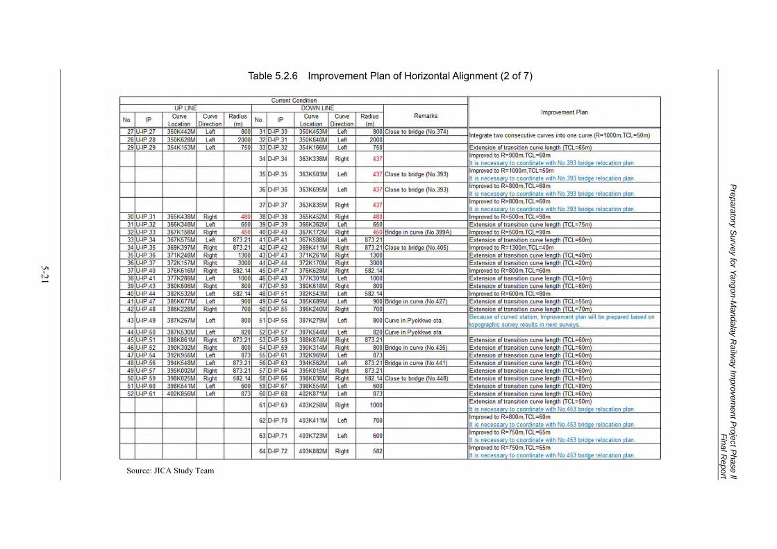
Preparatory S
urvey for Yangon-Mandalay R
ailway Im
provement P
roject Phase ll
Final Report
5-21
Table 5.2.6 Improvement Plan of Horizontal Alignment (2 of 7)
Source: JICA Study Team
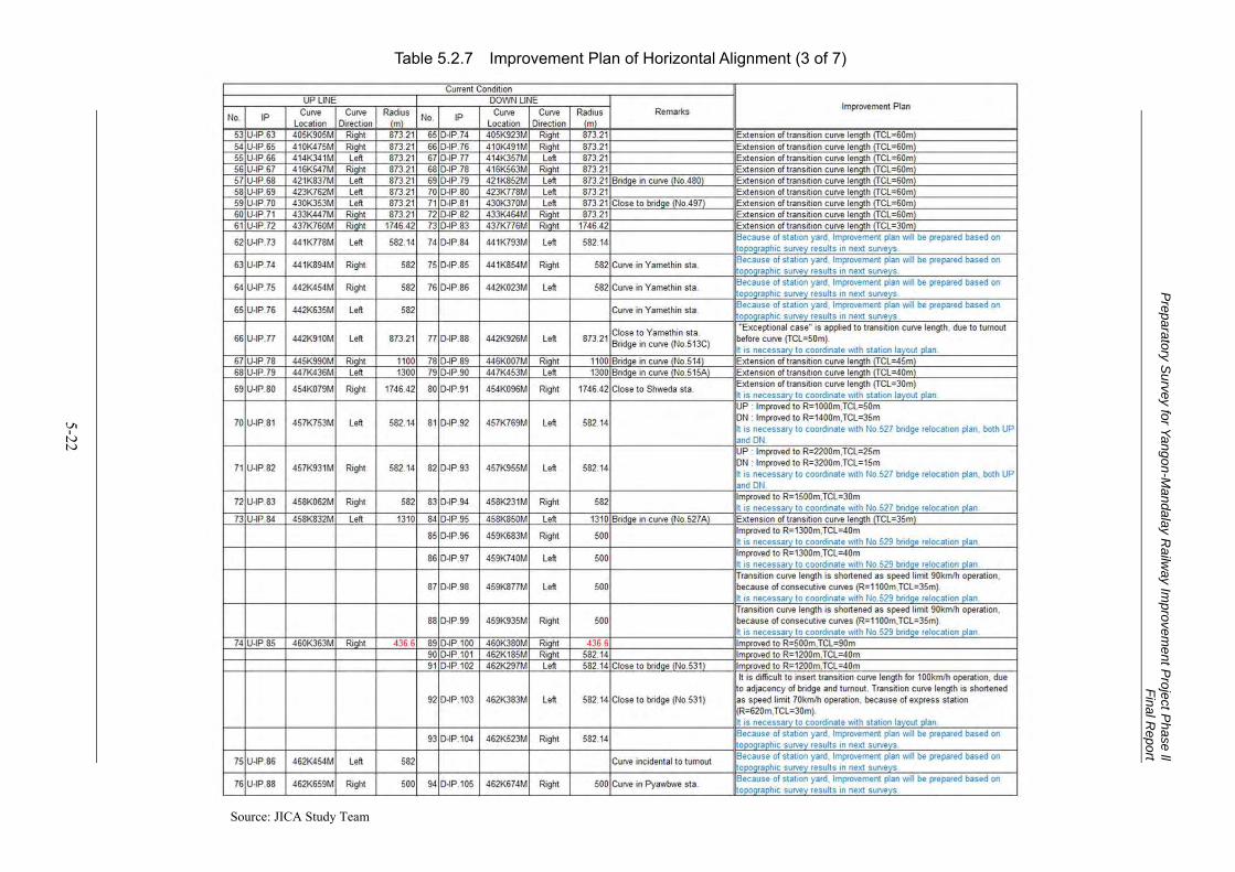
Preparatory S
urvey for Yangon-Mandalay R
ailway Im
provement P
roject Phase ll
Final Report
5-22
Table 5.2.7 Improvement Plan of Horizontal Alignment (3 of 7)
Source: JICA Study Team
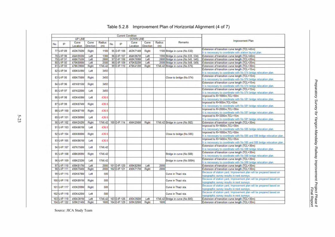
Preparatory S
urvey for Yangon-Mandalay R
ailway Im
provement P
roject Phase ll
Final Report
5-23
Table 5.2.8 Improvement Plan of Horizontal Alignment (4 of 7)
Source: JICA Study Team
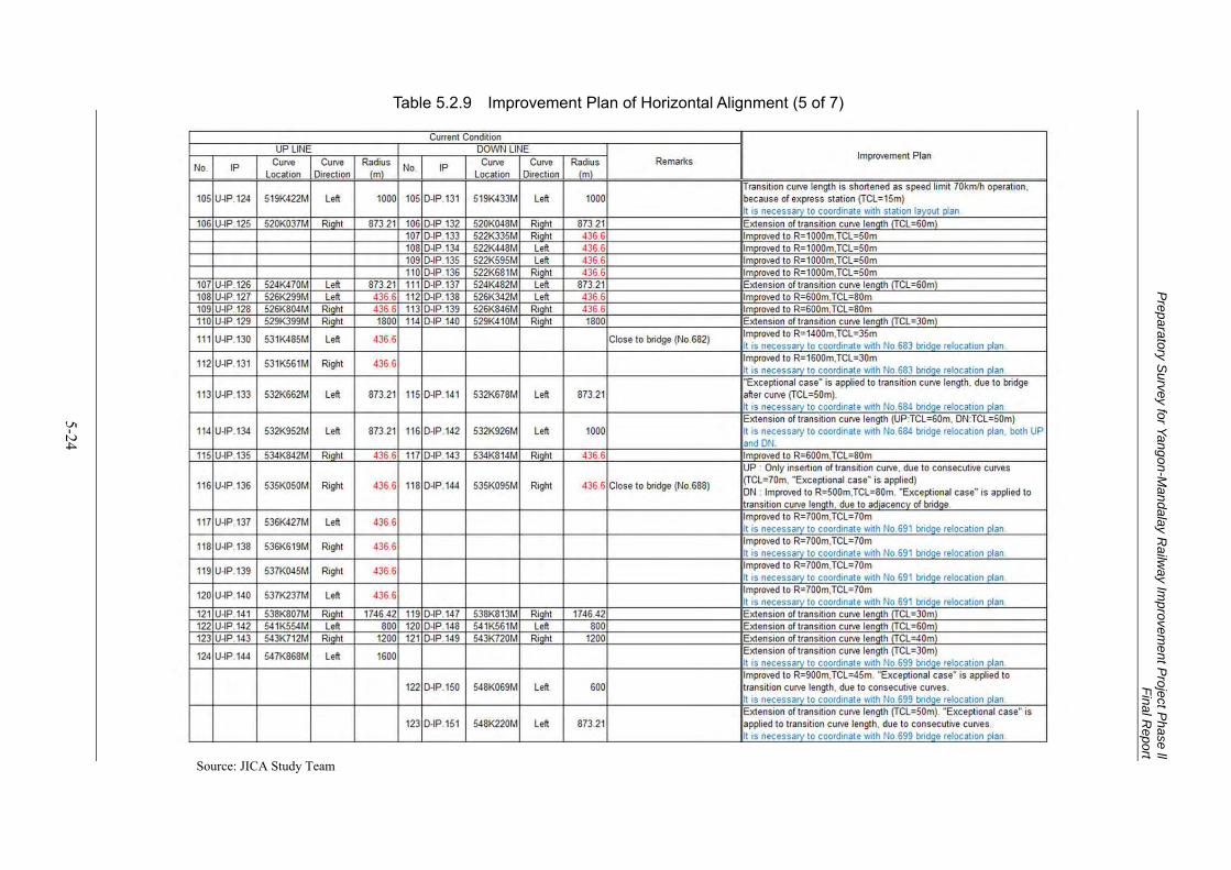
Preparatory S
urvey for Yangon-Mandalay R
ailway Im
provement P
roject Phase ll
Final Report
5-24
Table 5.2.9 Improvement Plan of Horizontal Alignment (5 of 7)
Source: JICA Study Team

Preparatory S
urvey for Yangon-Mandalay R
ailway Im
provement P
roject Phase ll
Final Report
5-25
Table 5.2.10 Improvement Plan of Horizontal Alignment (6 of 7)
Source: JICA Study Team
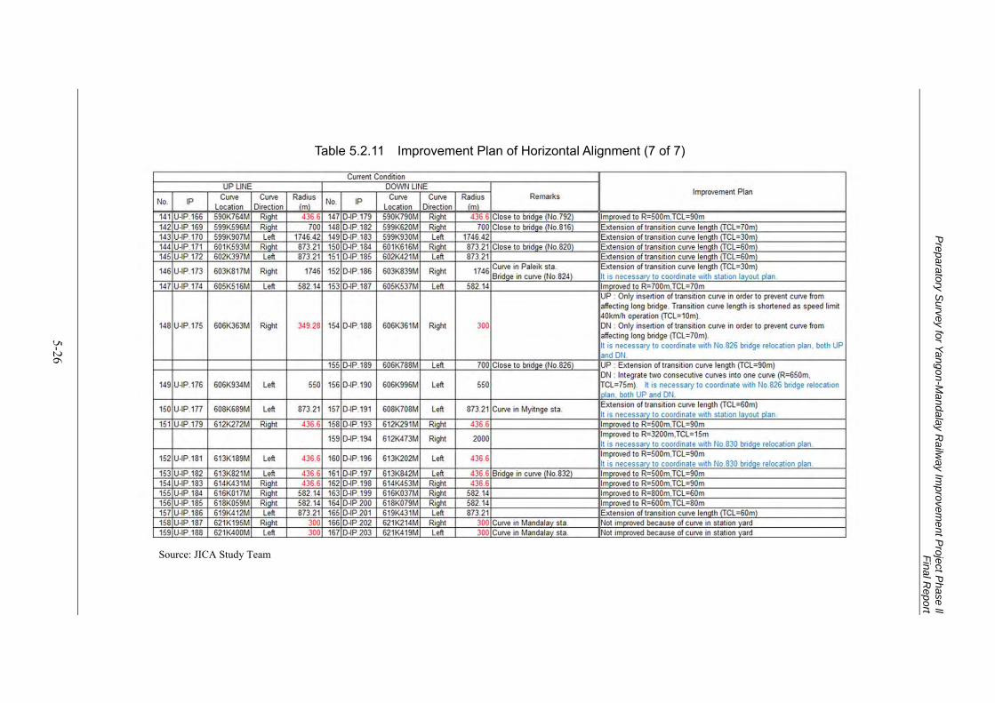
Preparatory S
urvey for Yangon-Mandalay R
ailway Im
provement P
roject Phase ll
Final Report
5-26
Table 5.2.11 Improvement Plan of Horizontal Alignment (7 of 7)
Source: JICA Study Team
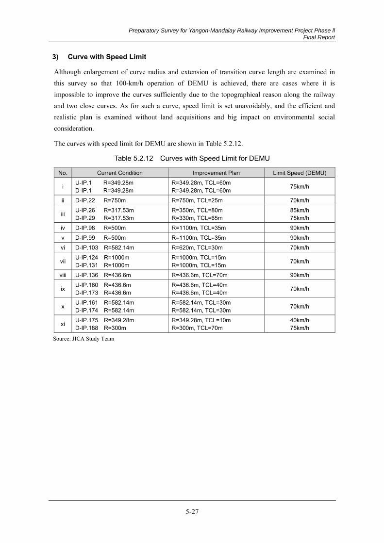
Preparatory Survey for Yangon-Mandalay Railway Improvement Project Phase ll Final Report
5-27
3) Curve with Speed Limit
Although enlargement of curve radius and extension of transition curve length are examined in this survey so that 100-km/h operation of DEMU is achieved, there are cases where it is impossible to improve the curves sufficiently due to the topographical reason along the railway and two close curves. As for such a curve, speed limit is set unavoidably, and the efficient and realistic plan is examined without land acquisitions and big impact on environmental social consideration.
The curves with speed limit for DEMU are shown in Table 5.2.12.
Table 5.2.12 Curves with Speed Limit for DEMU
No. Current Condition Improvement Plan Limit Speed (DEMU)
i U-IP.1 R=349.28m D-IP.1 R=349.28m
R=349.28m, TCL=60m R=349.28m, TCL=60m 75km/h
ii D-IP.22 R=750m R=750m, TCL=25m 70km/h
iii U-IP.26 R=317.53m D-IP.29 R=317.53m
R=350m, TCL=80m R=330m, TCL=65m
85km/h 75km/h
iv D-IP.98 R=500m R=1100m, TCL=35m 90km/h v D-IP.99 R=500m R=1100m, TCL=35m 90km/h vi D-IP.103 R=582.14m R=620m, TCL=30m 70km/h
vii U-IP.124 R=1000m D-IP.131 R=1000m
R=1000m, TCL=15m R=1000m, TCL=15m 70km/h
viii U-IP.136 R=436.6m R=436.6m, TCL=70m 90km/h
ix U-IP.160 R=436.6m D-IP.173 R=436.6m
R=436.6m, TCL=40m R=436.6m, TCL=40m 70km/h
x U-IP.161 R=582.14m D-IP.174 R=582.14m
R=582.14m, TCL=30m R=582.14m, TCL=30m 70km/h
xi U-IP.175 R=349.28m D-IP.188 R=300m
R=349.28m, TCL=10m R=300m, TCL=70m
40km/h 75km/h
Source: JICA Study Team
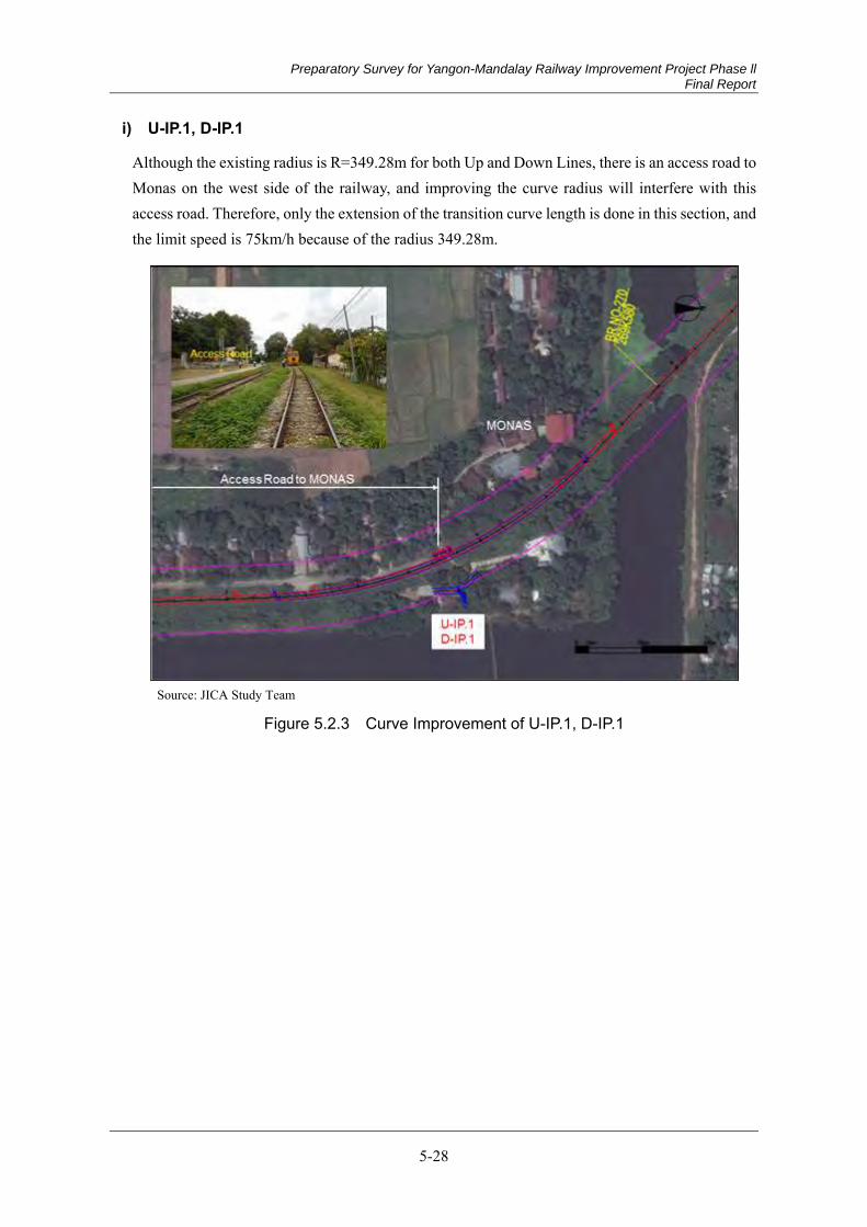
Preparatory Survey for Yangon-Mandalay Railway Improvement Project Phase ll Final Report
5-28
i) U-IP.1, D-IP.1
Although the existing radius is R=349.28m for both Up and Down Lines, there is an access road to Monas on the west side of the railway, and improving the curve radius will interfere with this access road. Therefore, only the extension of the transition curve length is done in this section, and the limit speed is 75km/h because of the radius 349.28m.
Source: JICA Study Team
Figure 5.2.3 Curve Improvement of U-IP.1, D-IP.1

Preparatory Survey for Yangon-Mandalay Railway Improvement Project Phase ll Final Report
5-29
ii) D-IP.22
Although the existing radius is R=750m and the transition curve length is extended, it is difficult to insert the transition curve for 100km/h operation (TCL=65m) due to adjacency of turnout in Thawati station before curve and consecutive curves after curve. Thawati station is the express station where all trains stop, so the design speed before and after station is reduced to 70km/h, and the transition curve length is shortened.
In order to decide the curve improvement plan, it is necessary to coordinate with the station layout plan of Thawati station.
Source: JICA Study Team
Figure 5.2.4 Curve Improvement of D-IP.22

Preparatory Survey for Yangon-Mandalay Railway Improvement Project Phase ll Final Report
5-30
iii) U-IP.26, D-IP.29
Although the existing radius is R=317.53m for both Up and Down Lines, there is the No.373 bridge before curve, improving the radius to 500m will affect the bridge. Therefore, the improvements are done so that the curve does not affect the bridge in this section. Curve radius is improved to R=350m for Up Line and R=330m for Down Line. The limit speed is 85km/h for Up Line and 75km/h for Down Line because of the curve radius.
There is a No.373 bridge relocation plan, in order to decide the curve improvement plan, it is necessary to coordinate with the bridge relocation plan.
Source: JICA Study Team
Figure 5.2.5 Curve Improvement of U-IP.26, D-IP.29
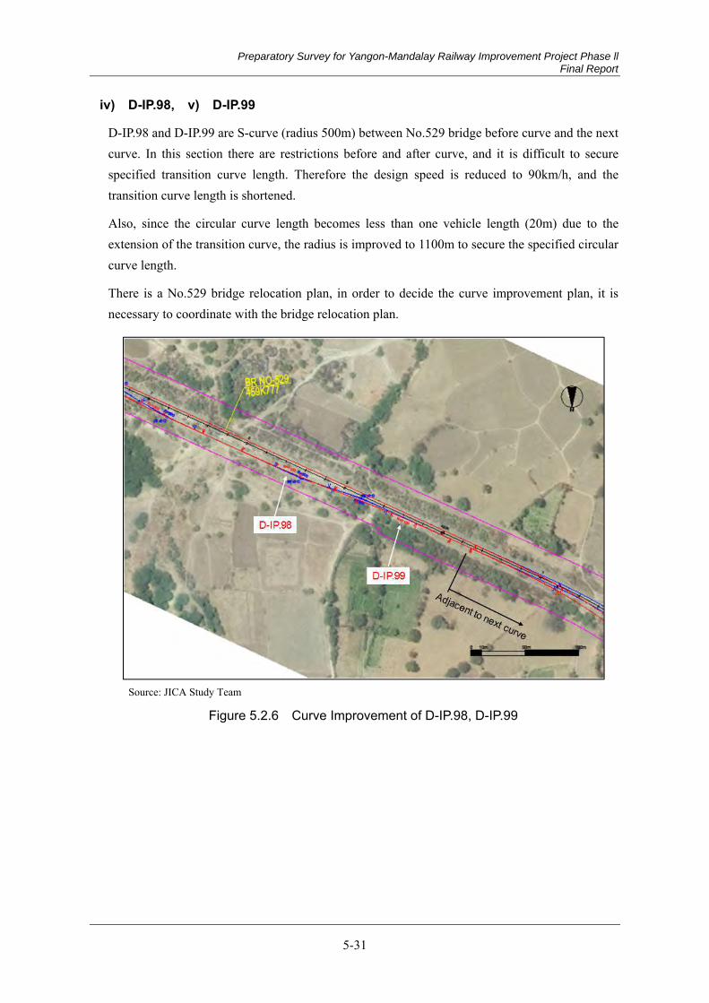
Preparatory Survey for Yangon-Mandalay Railway Improvement Project Phase ll Final Report
5-31
iv) D-IP.98, v) D-IP.99
D-IP.98 and D-IP.99 are S-curve (radius 500m) between No.529 bridge before curve and the next curve. In this section there are restrictions before and after curve, and it is difficult to secure specified transition curve length. Therefore the design speed is reduced to 90km/h, and the transition curve length is shortened.
Also, since the circular curve length becomes less than one vehicle length (20m) due to the extension of the transition curve, the radius is improved to 1100m to secure the specified circular curve length.
There is a No.529 bridge relocation plan, in order to decide the curve improvement plan, it is necessary to coordinate with the bridge relocation plan.
Source: JICA Study Team
Figure 5.2.6 Curve Improvement of D-IP.98, D-IP.99
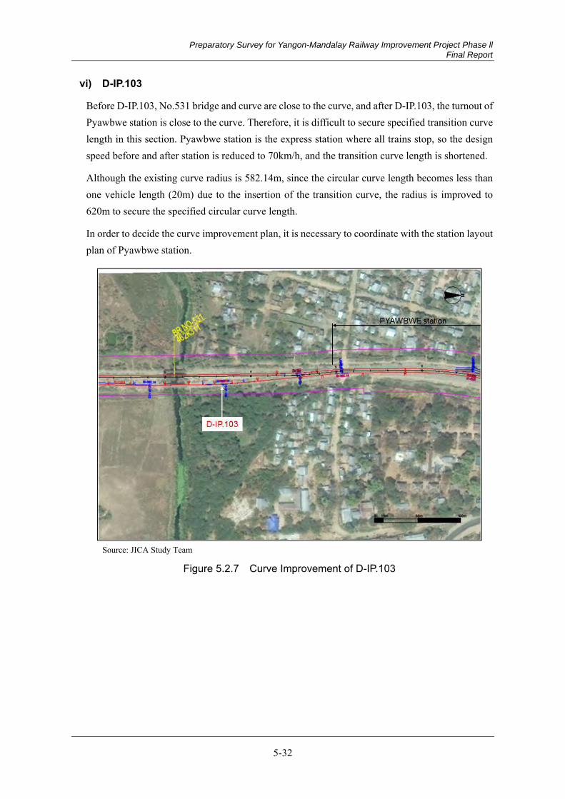
Preparatory Survey for Yangon-Mandalay Railway Improvement Project Phase ll Final Report
5-32
vi) D-IP.103
Before D-IP.103, No.531 bridge and curve are close to the curve, and after D-IP.103, the turnout of Pyawbwe station is close to the curve. Therefore, it is difficult to secure specified transition curve length in this section. Pyawbwe station is the express station where all trains stop, so the design speed before and after station is reduced to 70km/h, and the transition curve length is shortened.
Although the existing curve radius is 582.14m, since the circular curve length becomes less than one vehicle length (20m) due to the insertion of the transition curve, the radius is improved to 620m to secure the specified circular curve length.
In order to decide the curve improvement plan, it is necessary to coordinate with the station layout plan of Pyawbwe station.
Source: JICA Study Team
Figure 5.2.7 Curve Improvement of D-IP.103
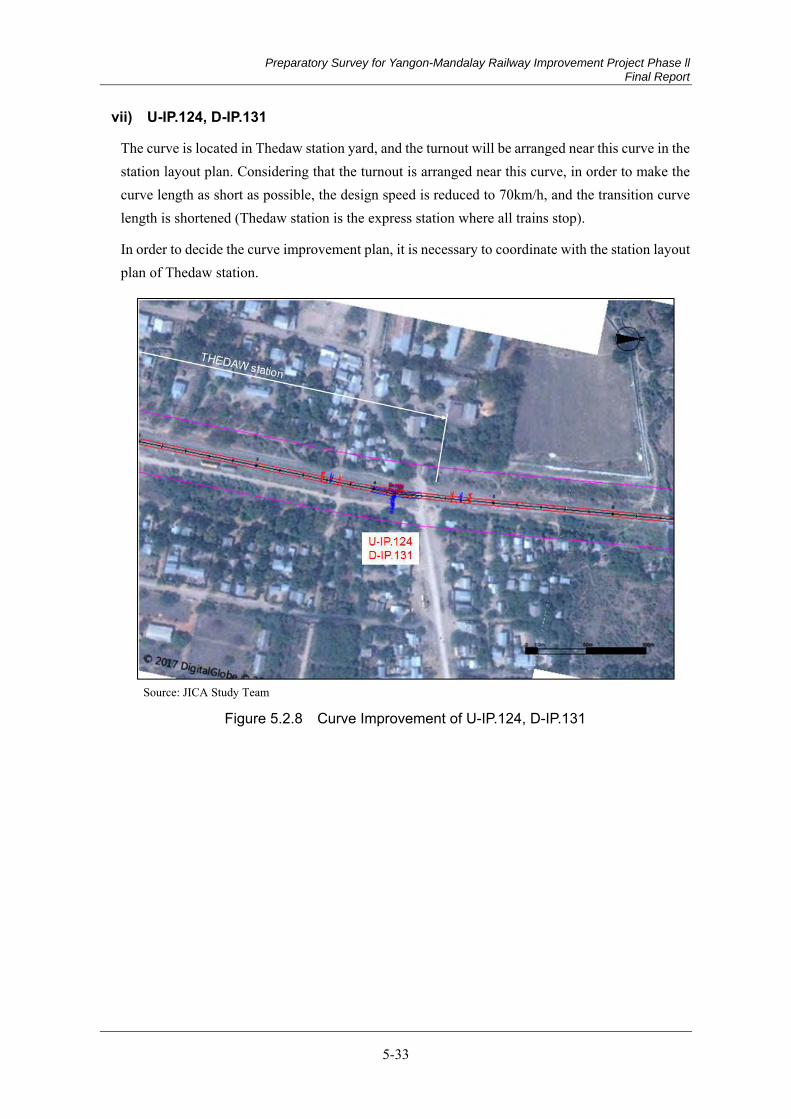
Preparatory Survey for Yangon-Mandalay Railway Improvement Project Phase ll Final Report
5-33
vii) U-IP.124, D-IP.131
The curve is located in Thedaw station yard, and the turnout will be arranged near this curve in the station layout plan. Considering that the turnout is arranged near this curve, in order to make the curve length as short as possible, the design speed is reduced to 70km/h, and the transition curve length is shortened (Thedaw station is the express station where all trains stop).
In order to decide the curve improvement plan, it is necessary to coordinate with the station layout plan of Thedaw station.
Source: JICA Study Team
Figure 5.2.8 Curve Improvement of U-IP.124, D-IP.131
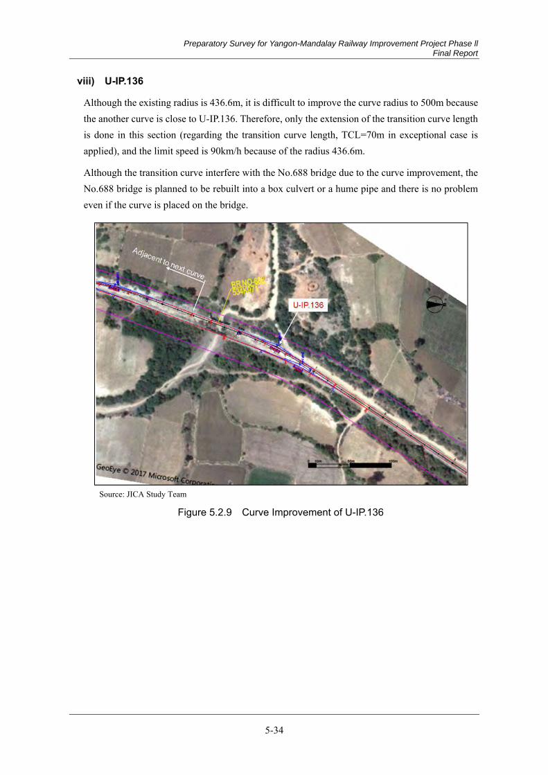
Preparatory Survey for Yangon-Mandalay Railway Improvement Project Phase ll Final Report
5-34
viii) U-IP.136
Although the existing radius is 436.6m, it is difficult to improve the curve radius to 500m because the another curve is close to U-IP.136. Therefore, only the extension of the transition curve length is done in this section (regarding the transition curve length, TCL=70m in exceptional case is applied), and the limit speed is 90km/h because of the radius 436.6m.
Although the transition curve interfere with the No.688 bridge due to the curve improvement, the No.688 bridge is planned to be rebuilt into a box culvert or a hume pipe and there is no problem even if the curve is placed on the bridge.
Source: JICA Study Team
Figure 5.2.9 Curve Improvement of U-IP.136
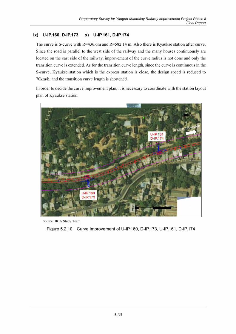
Preparatory Survey for Yangon-Mandalay Railway Improvement Project Phase ll Final Report
5-35
ix) U-IP.160, D-IP.173 x) U-IP.161, D-IP.174
The curve is S-curve with R=436.6m and R=582.14 m. Also there is Kyaukse station after curve. Since the road is parallel to the west side of the railway and the many houses continuously are located on the east side of the railway, improvement of the curve radius is not done and only the transition curve is extended. As for the transition curve length, since the curve is continuous in the S-curve, Kyaukse station which is the express station is close, the design speed is reduced to 70km/h, and the transition curve length is shortened.
In order to decide the curve improvement plan, it is necessary to coordinate with the station layout plan of Kyaukse station.
Source: JICA Study Team
Figure 5.2.10 Curve Improvement of U-IP.160, D-IP.173, U-IP.161, D-IP.174

Preparatory Survey for Yangon-Mandalay Railway Improvement Project Phase ll Final Report
5-36
xi) U-IP.175, D-IP.188
Although the curve radius is R=349.28m for Up Line and R=300m for Down Line, No.826 bridge is close to these curves at the end point of the curves, only insertion of the transition curve is done without improvement of the curve radius.
The curve of the Up Line is close to the bridge and there is almost no straight line length enough to insert the transition curve. Therefore, the transition curve can be inserted only 10m-length and it is necessary to set the speed limit of 40km/h.
The transition curve of TCL=70m can be inserted for the Down Line, and the speed limit is 75km/h because of the curve radius of 300m.
There is a No.826 bridge relocation plan, in order to decide the curve improvement plan, it is necessary to coordinate with the bridge relocation plan.
Source: JICA Study Team
Figure 5.2.11 Curve Improvement of U-IP.175, D-IP.188
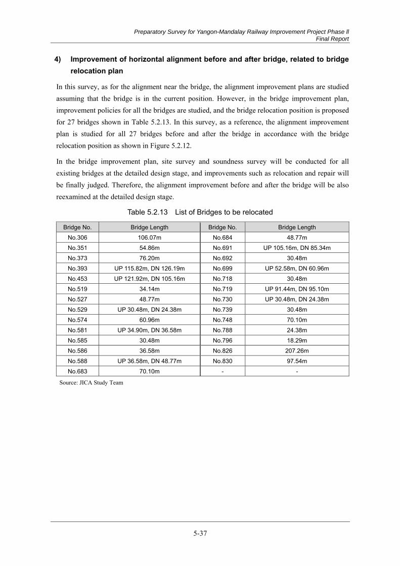
Preparatory Survey for Yangon-Mandalay Railway Improvement Project Phase ll Final Report
5-37
4) Improvement of horizontal alignment before and after bridge, related to bridge relocation plan
In this survey, as for the alignment near the bridge, the alignment improvement plans are studied assuming that the bridge is in the current position. However, in the bridge improvement plan, improvement policies for all the bridges are studied, and the bridge relocation position is proposed for 27 bridges shown in Table 5.2.13. In this survey, as a reference, the alignment improvement plan is studied for all 27 bridges before and after the bridge in accordance with the bridge relocation position as shown in Figure 5.2.12.
In the bridge improvement plan, site survey and soundness survey will be conducted for all existing bridges at the detailed design stage, and improvements such as relocation and repair will be finally judged. Therefore, the alignment improvement before and after the bridge will be also reexamined at the detailed design stage.
Table 5.2.13 List of Bridges to be relocated
Bridge No. Bridge Length Bridge No. Bridge Length No.306 106.07m No.684 48.77m No.351 54.86m No.691 UP 105.16m, DN 85.34m No.373 76.20m No.692 30.48m No.393 UP 115.82m, DN 126.19m No.699 UP 52.58m, DN 60.96m No.453 UP 121.92m, DN 105.16m No.718 30.48m No.519 34.14m No.719 UP 91.44m, DN 95.10m No.527 48.77m No.730 UP 30.48m, DN 24.38m No.529 UP 30.48m, DN 24.38m No.739 30.48m No.574 60.96m No.748 70.10m No.581 UP 34.90m, DN 36.58m No.788 24.38m No.585 30.48m No.796 18.29m No.586 36.58m No.826 207.26m No.588 UP 36.58m, DN 48.77m No.830 97.54m No.683 70.10m - -
Source: JICA Study Team
Preparatory Survey for Yangon-Mandalay Railway Improvement Project Phase ll Final Report
5-38
Source: JICA Study Team
Figure 5.2.12 Alignment Improvement before and after bridge related to bridge relocation plan (Example of Bridge No.306)
5.3 Track and Roadbed
Current Condition of Track and Roadbed 5.3.1
Specifications of Track Structure of Myanma Railway (1)
The major specifications of Myanma Railways are shown in Table 5.3.1.
Table 5.3.1 Specifications of Track Structure of Myanma Railway
Item Contents Comment Standard Gauge 1,000mm Maximum Lord 17.0 ton (12.5 ton) Minimum Curve Radius R=291m Maximum Gradient 10‰ 2,5‰ Station Yard and Storage Track Structure Gauge
Height 3,808 mm Width 3,810 mm
Vehicle Gauge
Coach Height 3,505 mm Width 2,819 mm
Freight Wagon
Height 3,429 mm Width 2,591 mm
Width of Formation
Single Track 6,096 mm Double Track 9,906 mm
Turnout 1:12 1:8.5
Source: JICA Study Team
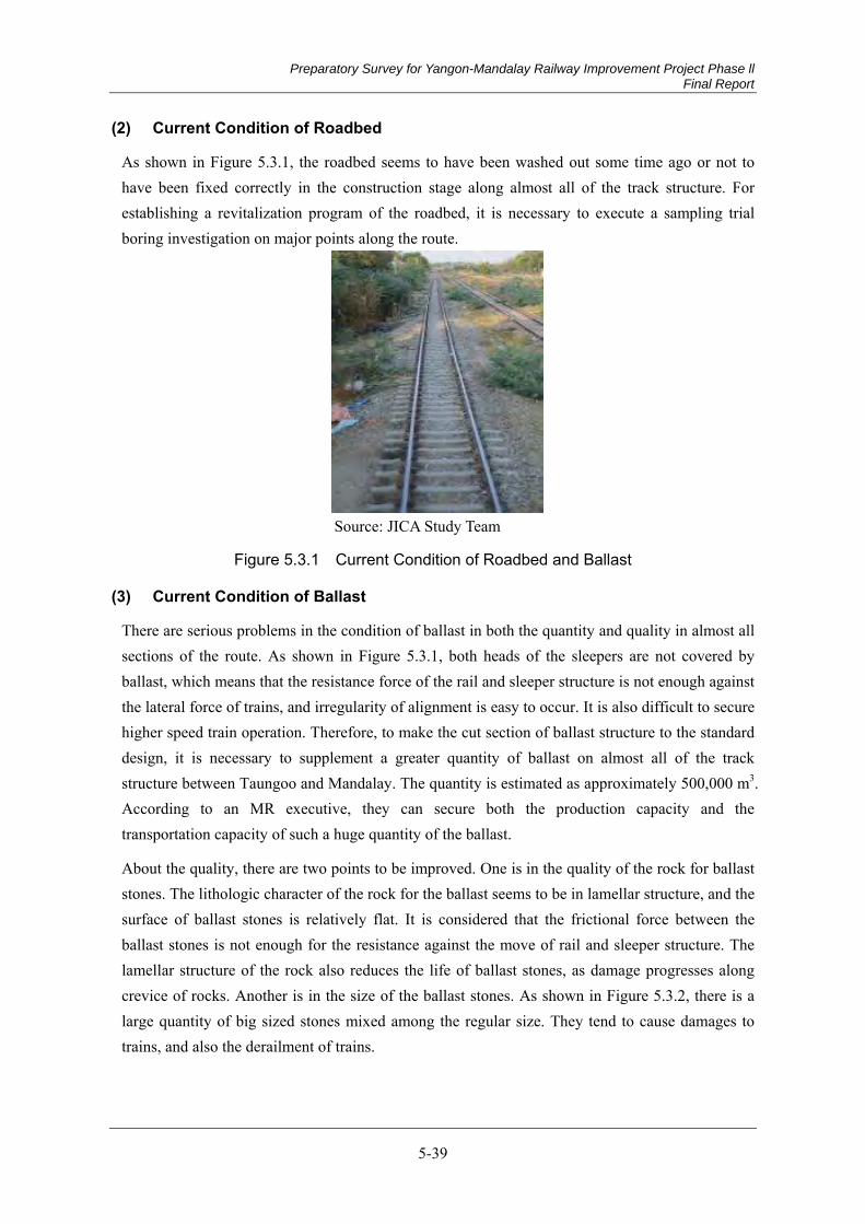
Preparatory Survey for Yangon-Mandalay Railway Improvement Project Phase ll Final Report
5-39
Current Condition of Roadbed (2)
As shown in Figure 5.3.1, the roadbed seems to have been washed out some time ago or not to have been fixed correctly in the construction stage along almost all of the track structure. For establishing a revitalization program of the roadbed, it is necessary to execute a sampling trial boring investigation on major points along the route.
Source: JICA Study Team
Figure 5.3.1 Current Condition of Roadbed and Ballast
Current Condition of Ballast (3)
There are serious problems in the condition of ballast in both the quantity and quality in almost all sections of the route. As shown in Figure 5.3.1, both heads of the sleepers are not covered by ballast, which means that the resistance force of the rail and sleeper structure is not enough against the lateral force of trains, and irregularity of alignment is easy to occur. It is also difficult to secure higher speed train operation. Therefore, to make the cut section of ballast structure to the standard design, it is necessary to supplement a greater quantity of ballast on almost all of the track structure between Taungoo and Mandalay. The quantity is estimated as approximately 500,000 m3. According to an MR executive, they can secure both the production capacity and the transportation capacity of such a huge quantity of the ballast.
About the quality, there are two points to be improved. One is in the quality of the rock for ballast stones. The lithologic character of the rock for the ballast seems to be in lamellar structure, and the surface of ballast stones is relatively flat. It is considered that the frictional force between the ballast stones is not enough for the resistance against the move of rail and sleeper structure. The lamellar structure of the rock also reduces the life of ballast stones, as damage progresses along crevice of rocks. Another is in the size of the ballast stones. As shown in Figure 5.3.2, there is a large quantity of big sized stones mixed among the regular size. They tend to cause damages to trains, and also the derailment of trains.
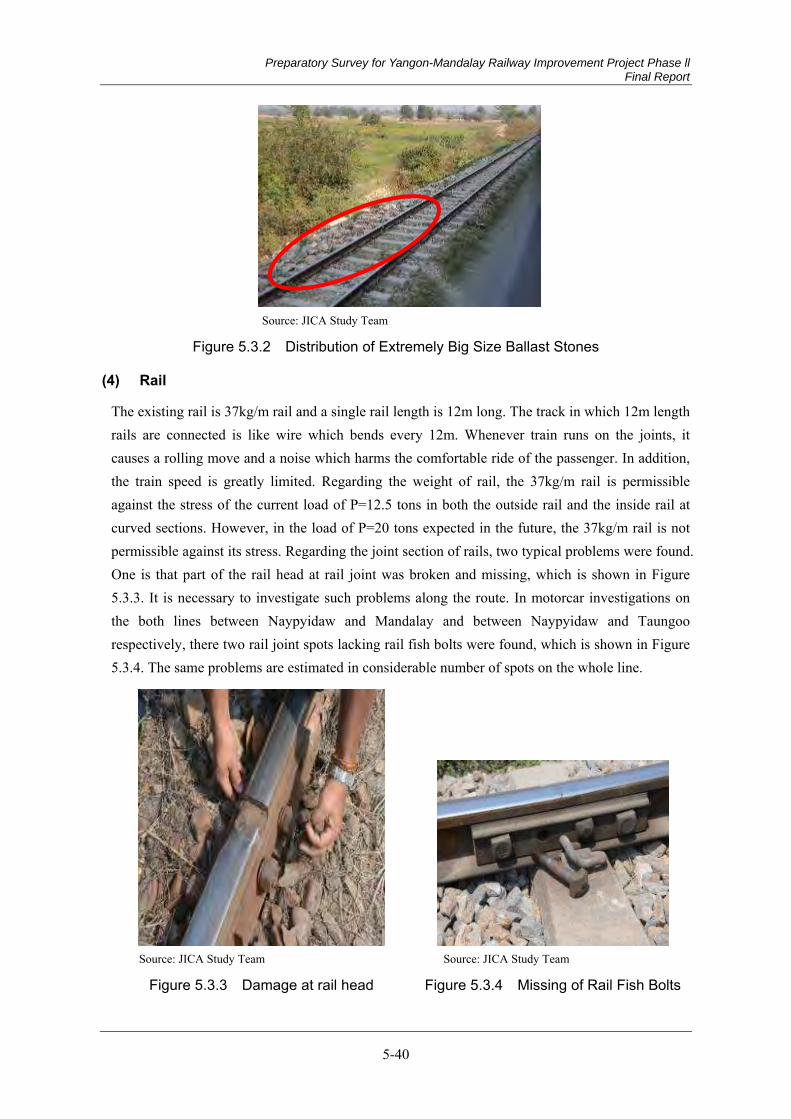
Preparatory Survey for Yangon-Mandalay Railway Improvement Project Phase ll Final Report
5-40
Source: JICA Study Team
Figure 5.3.2 Distribution of Extremely Big Size Ballast Stones
Rail (4)
The existing rail is 37kg/m rail and a single rail length is 12m long. The track in which 12m length rails are connected is like wire which bends every 12m. Whenever train runs on the joints, it causes a rolling move and a noise which harms the comfortable ride of the passenger. In addition, the train speed is greatly limited. Regarding the weight of rail, the 37kg/m rail is permissible against the stress of the current load of P=12.5 tons in both the outside rail and the inside rail at curved sections. However, in the load of P=20 tons expected in the future, the 37kg/m rail is not permissible against its stress. Regarding the joint section of rails, two typical problems were found. One is that part of the rail head at rail joint was broken and missing, which is shown in Figure 5.3.3. It is necessary to investigate such problems along the route. In motorcar investigations on the both lines between Naypyidaw and Mandalay and between Naypyidaw and Taungoo respectively, there two rail joint spots lacking rail fish bolts were found, which is shown in Figure 5.3.4. The same problems are estimated in considerable number of spots on the whole line.
Source: JICA Study Team Source: JICA Study Team
Figure 5.3.3 Damage at rail head Figure 5.3.4 Missing of Rail Fish Bolts
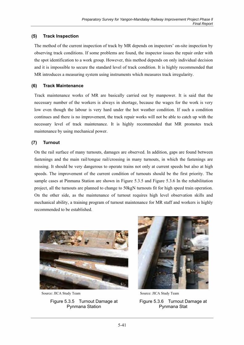
Preparatory Survey for Yangon-Mandalay Railway Improvement Project Phase ll Final Report
5-41
Track Inspection (5)
The method of the current inspection of track by MR depends on inspectors’ on-site inspection by observing track conditions. If some problems are found, the inspector issues the repair order with the spot identification to a work group. However, this method depends on only individual decision and it is impossible to secure the standard level of track condition. It is highly recommended that MR introduces a measuring system using instruments which measures track irregularity.
Track Maintenance (6)
Track maintenance works of MR are basically carried out by manpower. It is said that the necessary number of the workers is always in shortage, because the wages for the work is very low even though the labour is very hard under the hot weather condition. If such a condition continues and there is no improvement, the track repair works will not be able to catch up with the necessary level of track maintenance. It is highly recommended that MR promotes track maintenance by using mechanical power.
Turnout (7)
On the rail surface of many turnouts, damages are observed. In addition, gaps are found between fastenings and the main rail/tongue rail/crossing in many turnouts, in which the fastenings are missing. It should be very dangerous to operate trains not only at current speeds but also at high speeds. The improvement of the current condition of turnouts should be the first priority. The sample cases at Pinmana Station are shown in Figure 5.3.5 and Figure 5.3.6 In the rehabilitation project, all the turnouts are planned to change to 50kgN turnouts fit for high speed train operation. On the other side, as the maintenance of turnout requires high level observation skills and mechanical ability, a training program of turnout maintenance for MR staff and workers is highly recommended to be established.
Source: JICA Study Team Source: JICA Study Team
Figure 5.3.5 Turnout Damage at Pynmana Station
Figure 5.3.6 Turnout Damage at Pynmana Stat
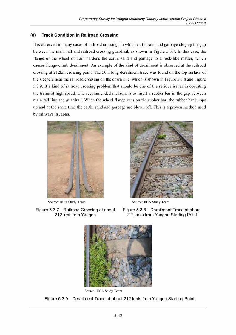
Preparatory Survey for Yangon-Mandalay Railway Improvement Project Phase ll Final Report
5-42
Track Condition in Railroad Crossing (8)
It is observed in many cases of railroad crossings in which earth, sand and garbage clog up the gap between the main rail and railroad crossing guardrail, as shown in Figure 5.3.7. In this case, the flange of the wheel of train hardens the earth, sand and garbage to a rock-like matter, which causes flange-climb derailment. An example of the kind of derailment is observed at the railroad crossing at 212km crossing point. The 50m long derailment trace was found on the top surface of the sleepers near the railroad crossing on the down line, which is shown in Figure 5.3.8 and Figure 5.3.9. It’s kind of railroad crossing problem that should be one of the serious issues in operating the trains at high speed. One recommended measure is to insert a rubber bar in the gap between main rail line and guardrail. When the wheel flange runs on the rubber bar, the rubber bar jumps up and at the same time the earth, sand and garbage are blown off. This is a proven method used by railways in Japan.
Source: JICA Study Team Source: JICA Study Team
Figure 5.3.7 Railroad Crossing at about 212 kmi from Yangon
Figure 5.3.8 Derailment Trace at about 212 kmis from Yangon Starting Point
Source: JICA Study Team
Figure 5.3.9 Derailment Trace at about 212 kmis from Yangon Starting Point
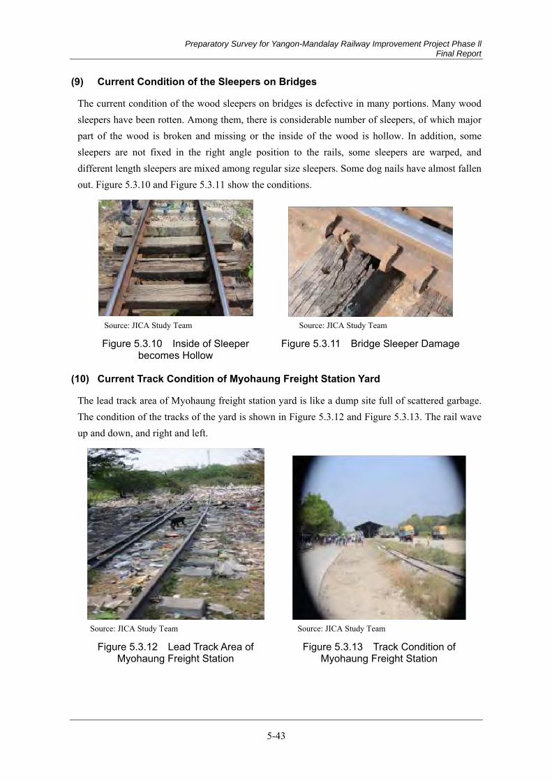
Preparatory Survey for Yangon-Mandalay Railway Improvement Project Phase ll Final Report
5-43
Current Condition of the Sleepers on Bridges (9)
The current condition of the wood sleepers on bridges is defective in many portions. Many wood sleepers have been rotten. Among them, there is considerable number of sleepers, of which major part of the wood is broken and missing or the inside of the wood is hollow. In addition, some sleepers are not fixed in the right angle position to the rails, some sleepers are warped, and different length sleepers are mixed among regular size sleepers. Some dog nails have almost fallen out. Figure 5.3.10 and Figure 5.3.11 show the conditions.
Source: JICA Study Team Source: JICA Study Team
Figure 5.3.10 Inside of Sleeper becomes Hollow
Figure 5.3.11 Bridge Sleeper Damage
Current Track Condition of Myohaung Freight Station Yard (10)
The lead track area of Myohaung freight station yard is like a dump site full of scattered garbage. The condition of the tracks of the yard is shown in Figure 5.3.12 and Figure 5.3.13. The rail wave up and down, and right and left.
Source: JICA Study Team Source: JICA Study Team
Figure 5.3.12 Lead Track Area of Myohaung Freight Station
Figure 5.3.13 Track Condition of Myohaung Freight Station
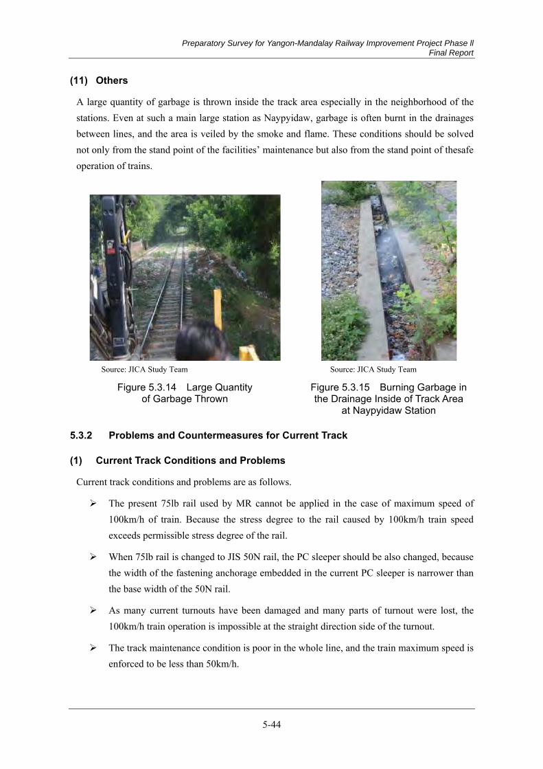
Preparatory Survey for Yangon-Mandalay Railway Improvement Project Phase ll Final Report
5-44
Others (11)
A large quantity of garbage is thrown inside the track area especially in the neighborhood of the stations. Even at such a main large station as Naypyidaw, garbage is often burnt in the drainages between lines, and the area is veiled by the smoke and flame. These conditions should be solved not only from the stand point of the facilities’ maintenance but also from the stand point of thesafe operation of trains.
Source: JICA Study Team Source: JICA Study Team
Figure 5.3.14 Large Quantity of Garbage Thrown
Figure 5.3.15 Burning Garbage in the Drainage Inside of Track Area
at Naypyidaw Station
Problems and Countermeasures for Current Track 5.3.2
Current Track Conditions and Problems (1)
Current track conditions and problems are as follows.
The present 75lb rail used by MR cannot be applied in the case of maximum speed of 100km/h of train. Because the stress degree to the rail caused by 100km/h train speed exceeds permissible stress degree of the rail.
When 75lb rail is changed to JIS 50N rail, the PC sleeper should be also changed, because the width of the fastening anchorage embedded in the current PC sleeper is narrower than the base width of the 50N rail.
As many current turnouts have been damaged and many parts of turnout were lost, the 100km/h train operation is impossible at the straight direction side of the turnout.
The track maintenance condition is poor in the whole line, and the train maximum speed is enforced to be less than 50km/h.

Preparatory Survey for Yangon-Mandalay Railway Improvement Project Phase ll Final Report
5-45
There are many areas where the quantity of the ballast is much less than the standard defined by MR, and in the areas the end faces of both sides of PC sleepers are exposed, which largely decreases track lateral resistance power.
Regarding railroad crossings, in many crossings, earth, sand and garbage are clogged up and solidified between guardrail and main line rail, which is in danger of causing derailment when train wheels pass on them.
The sub ballast seems to disappear on visual observation.
Train running is in the face of danger of derailment in several sections because of frequent theft occurrence of rail fastenings.
Improving methods for 100km/h train operation (2)
The recommendations to solve the problems mentioned above and to secure 100km/h train operation are as follows.
The rail of main line and sub-main line should be changed to JIS 50N rail basically.
PC sleepers fit for JIS 50N rail should also replace current sleepers.
The turnouts of main line and sub-main line should be changed to # 12 turnouts basically.
The track maintenance systems should be improved.
Continuous welded rail (CWR) should be installed for reliable 100km/h train running and improvement of passenger's riding comfort.
The sub-ballasts should be improved.
The ballast should be fulfilled in necessary sections. The current status of the quality of ballast should be investigated. If poor quality is found, the ballast should be changed to MR standard.
About the railroad crossing, the rubber pad should be installed between main rail line and guardrail. It is proved in Japan railways that the earth, sand and garbage between rails pop out when a train drives on the line with rubber pad.
FD clip should be installed in the sections of frequent occurrence of the theft of rail fastening devices.
Recommendation for Improvement of Track and Subballast/Roadbed 5.3.3
The key factors of the track structure was decided basically same as Yangon-Mandalay Railway improvement project phase-I.
Rail (1)
The calculation result of the comparison between “Bending Stress of the Rail” and “Allowable

Preparatory Survey for Yangon-Mandalay Railway Improvement Project Phase ll Final Report
5-46
Bending Stress of the Rail” is shown in Table 5.3.2. The prerequisites are (1) the comparison between BS75 (37 kg/m) rail and JIS (Japanese Industrial Standards) 50N rail, (2) the maximum axle loads are P=20 tons,16 tons and 14 tons, (3) allowable bending stress of JIS 50N and BS75 (37 kg/m) is 131.2 Mpa and 111.0 Mpa, respectively. (4) Calculations are made on both the outside and the inside of the rail at curved sections. The result shows that the stress of BS75 (37 kg/m) rail is beyond allowable level in all cases of the three types of axle loads except 14 tons (inside). On the other side, the stress of JIS 50N rail is less than the allowable level in the all cases of three types of axle loads even 20 tons (outside). Regarding the marketability of JIS 50N rail and UIC 54, the both have the similar marketability. However, from the price point of view, as the weight per unit of JIS 50N is less than UIC 54, JIS 50N has much advantage. The selection of JIS 50N is highly recommended. However, at Myohaung Freight Station, it is reasonable to use 37 kg/m rail.
Table 5.3.2 Allowable Stress of the Rail
Rail Axle load
JIS 50N (Mpa)
BS75 (Mpa) Remarks
20ton (the outside) 108.4<131.2 160.2>111.0 The permission bend-ing stress degree of the rail is 13.2 Mpa in JIS 50N and 111.0 Mpa in BS75 (37 kg/m).
20ton (the inside) 96.4<131.2 142.5>111.0 16ton (the outside) 86.7<131.2 128.2>111.0 16ton (the inside) 77.1<131.2 114.0>111.0 14ton (the outside) 75.9<131.2 112.1>111.0 14ton (the inside) 67.5<131.2 99.7<111.0
Source: JICA Team
Design Load (2)
Regarding the design load, the final report of “Republic of the Union of Myanmar Yangon/Mandalay Detail Design Investigation Phase I” is followed.
Source: JICA Study Team
Figure 5.3.16 Train Design Load
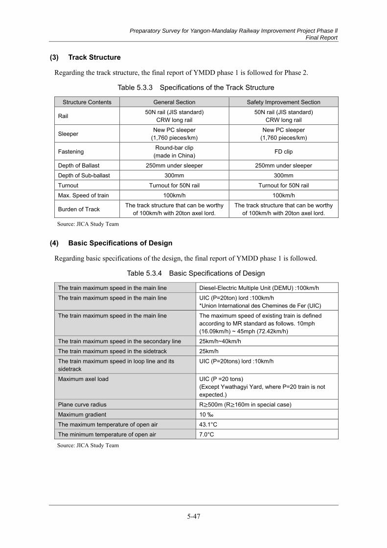
Preparatory Survey for Yangon-Mandalay Railway Improvement Project Phase ll Final Report
5-47
Track Structure (3)
Regarding the track structure, the final report of YMDD phase 1 is followed for Phase 2.
Table 5.3.3 Specifications of the Track Structure
Structure Contents General Section Safety Improvement Section
Rail 50N rail (JIS standard) CRW long rail
50N rail (JIS standard) CRW long rail
Sleeper New PC sleeper (1,760 pieces/km)
New PC sleeper (1,760 pieces/km)
Fastening Round-bar clip (made in China) FD clip
Depth of Ballast 250mm under sleeper 250mm under sleeper Depth of Sub-ballast 300mm 300mm Turnout Turnout for 50N rail Turnout for 50N rail Max. Speed of train 100km/h 100km/h
Burden of Track The track structure that can be worthy of 100km/h with 20ton axel lord.
The track structure that can be worthy of 100km/h with 20ton axel lord.
Source: JICA Study Team
Basic Specifications of Design (4)
Regarding basic specifications of the design, the final report of YMDD phase 1 is followed.
Table 5.3.4 Basic Specifications of Design
The train maximum speed in the main line Diesel-Electric Multiple Unit (DEMU) :100km/h The train maximum speed in the main line UIC (P=20ton) lord :100km/h
*Union International des Chemines de Fer (UIC) The train maximum speed in the main line The maximum speed of existing train is defined
according to MR standard as follows. 10mph (16.09km/h) ~ 45mph (72.42km/h)
The train maximum speed in the secondary line 25km/h~40km/h The train maximum speed in the sidetrack 25km/h The train maximum speed in loop line and its sidetrack
UIC (P=20tons) lord :10km/h
Maximum axel load UIC (P =20 tons) (Except Ywathagyi Yard, where P=20 train is not expected.)
Plane curve radius R 500m (R 160m in special case) Maximum gradient 10 ‰ The maximum temperature of open air 43.1°C The minimum temperature of open air 7.0°C
Source: JICA Study Team
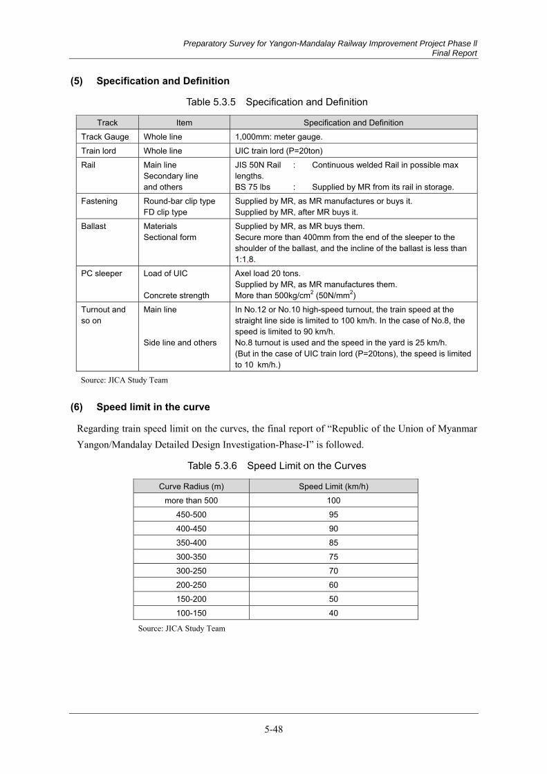
Preparatory Survey for Yangon-Mandalay Railway Improvement Project Phase ll Final Report
5-48
Specification and Definition (5)
Table 5.3.5 Specification and Definition
Track Item Specification and Definition Track Gauge Whole line 1,000mm: meter gauge. Train lord Whole line UIC train lord (P=20ton) Rail Main line
Secondary line and others
JIS 50N Rail : Continuous welded Rail in possible max lengths. BS 75 lbs : Supplied by MR from its rail in storage.
Fastening Round-bar clip type FD clip type
Supplied by MR, as MR manufactures or buys it. Supplied by MR, after MR buys it.
Ballast Materials Sectional form
Supplied by MR, as MR buys them. Secure more than 400mm from the end of the sleeper to the shoulder of the ballast, and the incline of the ballast is less than 1:1,8.
PC sleeper Load of UIC Concrete strength
Axel load 20 tons. Supplied by MR, as MR manufactures them. More than 500kg/cm2 (50N/mm2)
Turnout and so on
Main line Side line and others
In No.12 or No.10 high-speed turnout, the train speed at the straight line side is limited to 100 km/h. In the case of No.8, the speed is limited to 90 km/h. No.8 turnout is used and the speed in the yard is 25 km/h. (But in the case of UIC train lord (P=20tons), the speed is limited to 10 km/h.)
Source: JICA Study Team
Speed limit in the curve (6)
Regarding train speed limit on the curves, the final report of “Republic of the Union of Myanmar Yangon/Mandalay Detailed Design Investigation-Phase-I” is followed.
Table 5.3.6 Speed Limit on the Curves
Curve Radius (m) Speed Limit (km/h) more than 500 100
450-500 95 400-450 90 350-400 85 300-350 75 300-250 70 200-250 60 150-200 50 100-150 40
Source: JICA Study Team
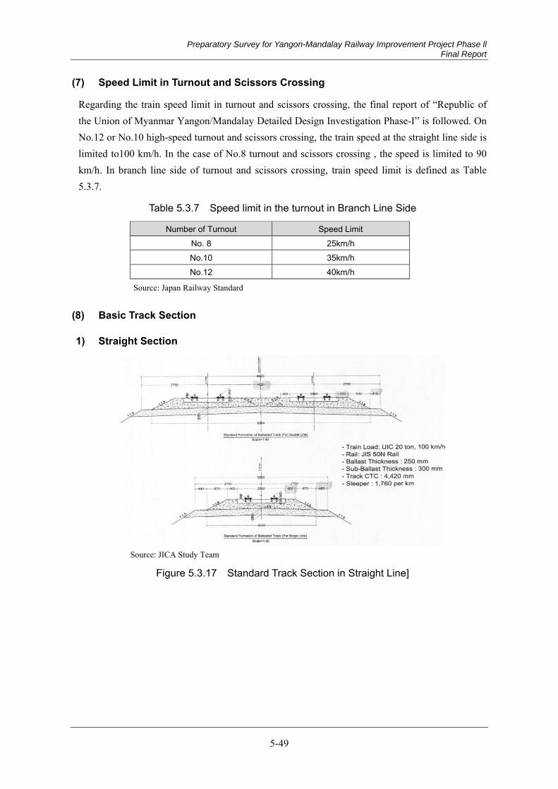
Preparatory Survey for Yangon-Mandalay Railway Improvement Project Phase ll Final Report
5-49
Speed Limit in Turnout and Scissors Crossing (7)
Regarding the train speed limit in turnout and scissors crossing, the final report of “Republic of the Union of Myanmar Yangon/Mandalay Detailed Design Investigation Phase-I” is followed. On No.12 or No.10 high-speed turnout and scissors crossing, the train speed at the straight line side is limited to100 km/h. In the case of No.8 turnout and scissors crossing , the speed is limited to 90 km/h. In branch line side of turnout and scissors crossing, train speed limit is defined as Table 5.3.7.
Table 5.3.7 Speed limit in the turnout in Branch Line Side
Number of Turnout Speed Limit No. 8 25km/h No.10 35km/h No.12 40km/h
Source: Japan Railway Standard
Basic Track Section (8)
1) Straight Section
Source: JICA Study Team
Figure 5.3.17 Standard Track Section in Straight Line]
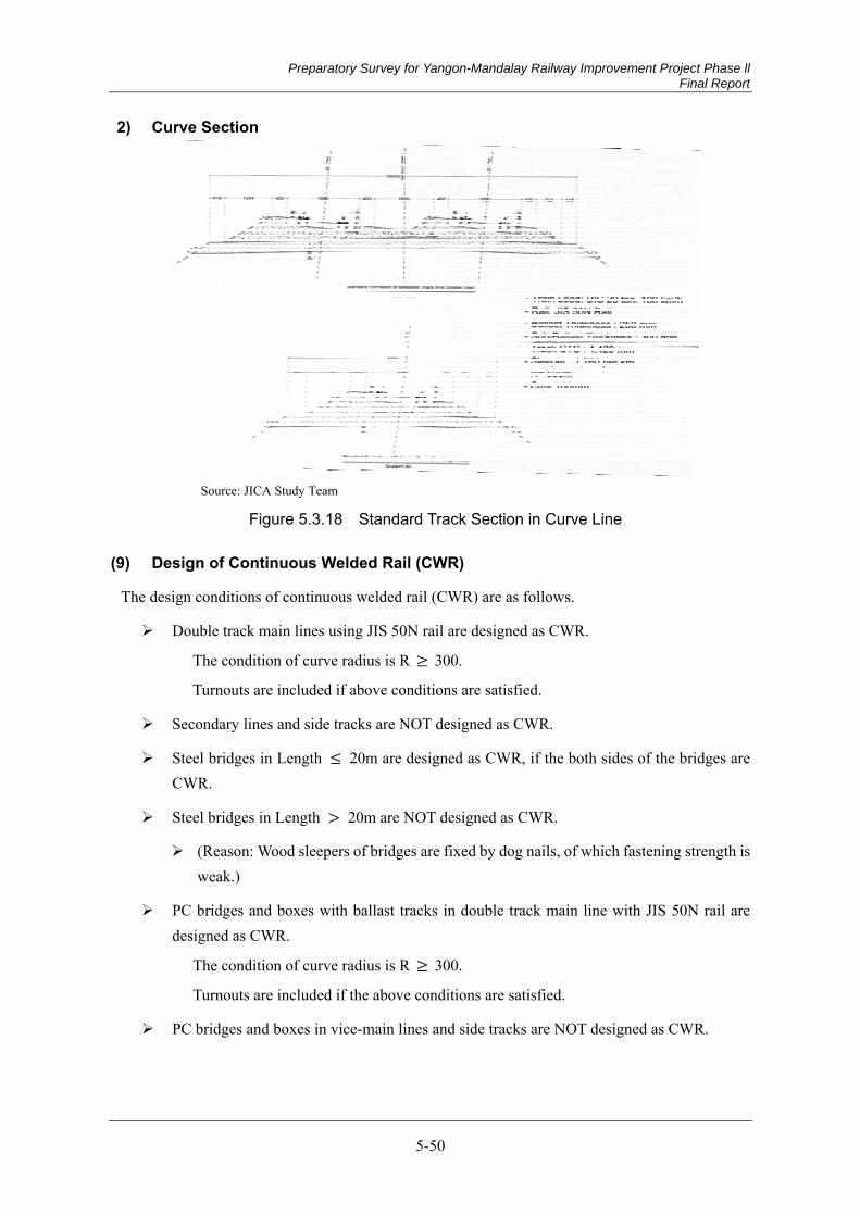
Preparatory Survey for Yangon-Mandalay Railway Improvement Project Phase ll Final Report
5-50
2) Curve Section
Source: JICA Study Team
Figure 5.3.18 Standard Track Section in Curve Line
Design of Continuous Welded Rail (CWR) (9)
The design conditions of continuous welded rail (CWR) are as follows.
Double track main lines using JIS 50N rail are designed as CWR.
The condition of curve radius is R 300.
Turnouts are included if above conditions are satisfied.
Secondary lines and side tracks are NOT designed as CWR.
Steel bridges in Length 20m are designed as CWR, if the both sides of the bridges are CWR.
Steel bridges in Length 20m are NOT designed as CWR.
(Reason: Wood sleepers of bridges are fixed by dog nails, of which fastening strength is weak.)
PC bridges and boxes with ballast tracks in double track main line with JIS 50N rail are designed as CWR.
The condition of curve radius is R 300.
Turnouts are included if the above conditions are satisfied.
PC bridges and boxes in vice-main lines and side tracks are NOT designed as CWR.
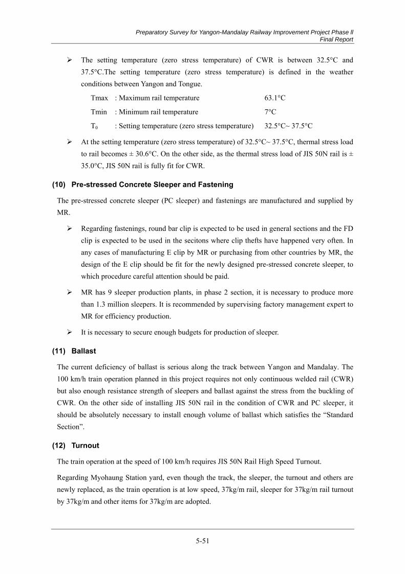
Preparatory Survey for Yangon-Mandalay Railway Improvement Project Phase ll Final Report
5-51
The setting temperature (zero stress temperature) of CWR is between 32.5°C and 37.5°C.The setting temperature (zero stress temperature) is defined in the weather conditions between Yangon and Tongue.
Tmax : Maximum rail temperature 63.1°C
Tmin : Minimum rail temperature 7°C
T0 : Setting temperature (zero stress temperature) 32.5°C~ 37.5°C
At the setting temperature (zero stress temperature) of 32.5°C~ 37.5°C, thermal stress load to rail becomes ± 30.6°C. On the other side, as the thermal stress load of JIS 50N rail is ± 35.0°C, JIS 50N rail is fully fit for CWR.
Pre-stressed Concrete Sleeper and Fastening (10)
The pre-stressed concrete sleeper (PC sleeper) and fastenings are manufactured and supplied by MR.
Regarding fastenings, round bar clip is expected to be used in general sections and the FD clip is expected to be used in the secitons where clip thefts have happened very often. In any cases of manufacturing E clip by MR or purchasing from other countries by MR, the design of the E clip should be fit for the newly designed pre-stressed concrete sleeper, to which procedure careful attention should be paid.
MR has 9 sleeper production plants, in phase 2 section, it is necessary to produce more than 1.3 million sleepers. It is recommended by supervising factory management expert to MR for efficiency production.
It is necessary to secure enough budgets for production of sleeper.
Ballast (11)
The current deficiency of ballast is serious along the track between Yangon and Mandalay. The 100 km/h train operation planned in this project requires not only continuous welded rail (CWR) but also enough resistance strength of sleepers and ballast against the stress from the buckling of CWR. On the other side of installing JIS 50N rail in the condition of CWR and PC sleeper, it should be absolutely necessary to install enough volume of ballast which satisfies the “Standard Section”.
Turnout (12)
The train operation at the speed of 100 km/h requires JIS 50N Rail High Speed Turnout.
Regarding Myohaung Station yard, even though the track, the sleeper, the turnout and others are newly replaced, as the train operation is at low speed, 37kg/m rail, sleeper for 37kg/m rail turnout by 37kg/m and other items for 37kg/m are adopted.
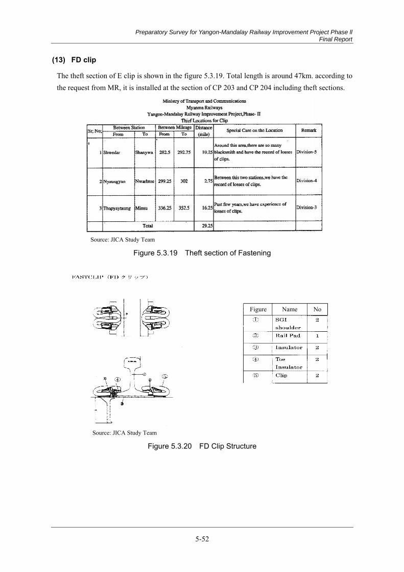
Preparatory Survey for Yangon-Mandalay Railway Improvement Project Phase ll Final Report
5-52
FD clip (13)
The theft section of E clip is shown in the figure 5.3.19. Total length is around 47km. according to the request from MR, it is installed at the section of CP 203 and CP 204 including theft sections.
Source: JICA Study Team
Figure 5.3.19 Theft section of Fastening
Source: JICA Study Team
Figure 5.3.20 FD Clip Structure
Figure Name No
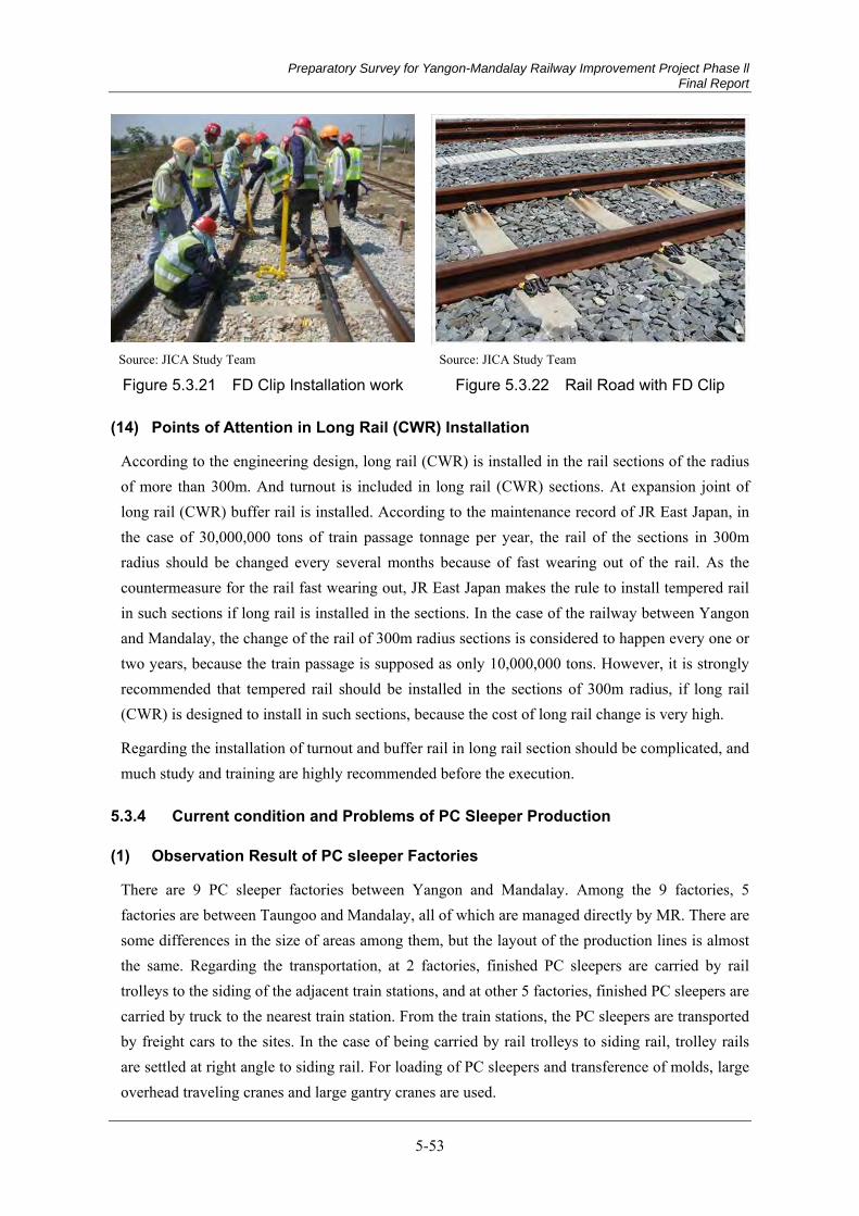
Preparatory Survey for Yangon-Mandalay Railway Improvement Project Phase ll Final Report
5-53
Source: JICA Study Team Source: JICA Study Team
Figure 5.3.21 FD Clip Installation work Figure 5.3.22 Rail Road with FD Clip
Points of Attention in Long Rail (CWR) Installation (14)
According to the engineering design, long rail (CWR) is installed in the rail sections of the radius of more than 300m. And turnout is included in long rail (CWR) sections. At expansion joint of long rail (CWR) buffer rail is installed. According to the maintenance record of JR East Japan, in the case of 30,000,000 tons of train passage tonnage per year, the rail of the sections in 300m radius should be changed every several months because of fast wearing out of the rail. As the countermeasure for the rail fast wearing out, JR East Japan makes the rule to install tempered rail in such sections if long rail is installed in the sections. In the case of the railway between Yangon and Mandalay, the change of the rail of 300m radius sections is considered to happen every one or two years, because the train passage is supposed as only 10,000,000 tons. However, it is strongly recommended that tempered rail should be installed in the sections of 300m radius, if long rail (CWR) is designed to install in such sections, because the cost of long rail change is very high.
Regarding the installation of turnout and buffer rail in long rail section should be complicated, and much study and training are highly recommended before the execution.
Current condition and Problems of PC Sleeper Production 5.3.4
Observation Result of PC sleeper Factories (1)
There are 9 PC sleeper factories between Yangon and Mandalay. Among the 9 factories, 5 factories are between Taungoo and Mandalay, all of which are managed directly by MR. There are some differences in the size of areas among them, but the layout of the production lines is almost the same. Regarding the transportation, at 2 factories, finished PC sleepers are carried by rail trolleys to the siding of the adjacent train stations, and at other 5 factories, finished PC sleepers are carried by truck to the nearest train station. From the train stations, the PC sleepers are transported by freight cars to the sites. In the case of being carried by rail trolleys to siding rail, trolley rails are settled at right angle to siding rail. For loading of PC sleepers and transference of molds, large overhead traveling cranes and large gantry cranes are used.

Preparatory Survey for Yangon-Mandalay Railway Improvement Project Phase ll Final Report
5-54
Source: JICA Study Team
Figure 5.3.23 Locations of 9 PC sleeper factories between Yangon and Mandalay
Source: JICA Study Team Source: JICA Study Team
Figure 5.3.24 Benches of PC sleeper factory
Figure 5.3.25 Molds of PC sleeper (4 PC sleepers can be produced
by one mold )

Preparatory Survey for Yangon-Mandalay Railway Improvement Project Phase ll Final Report
5-55
Source: JICA Study Team Source: JICA Study Team
Figure 5.3.26 Equipment to pull PC strand steel wire
Figure 5.3.27 PC strands
Source: JICA Study Team
Figure 5.3.28 Gantry Crane (Freight cars come under the gantry crane on siding rail)
The layout of production lines is almost the same most at each factory. But the facilities of Michgen factory are old and its production capacity is inferior to other factories because of the narrow factory area. It is said that the improvement plan of the factory is expected in the near future. Regarding the production quality of the factory, this factory still uses single line PC steel wire. But it is improved to use three strands in near future.
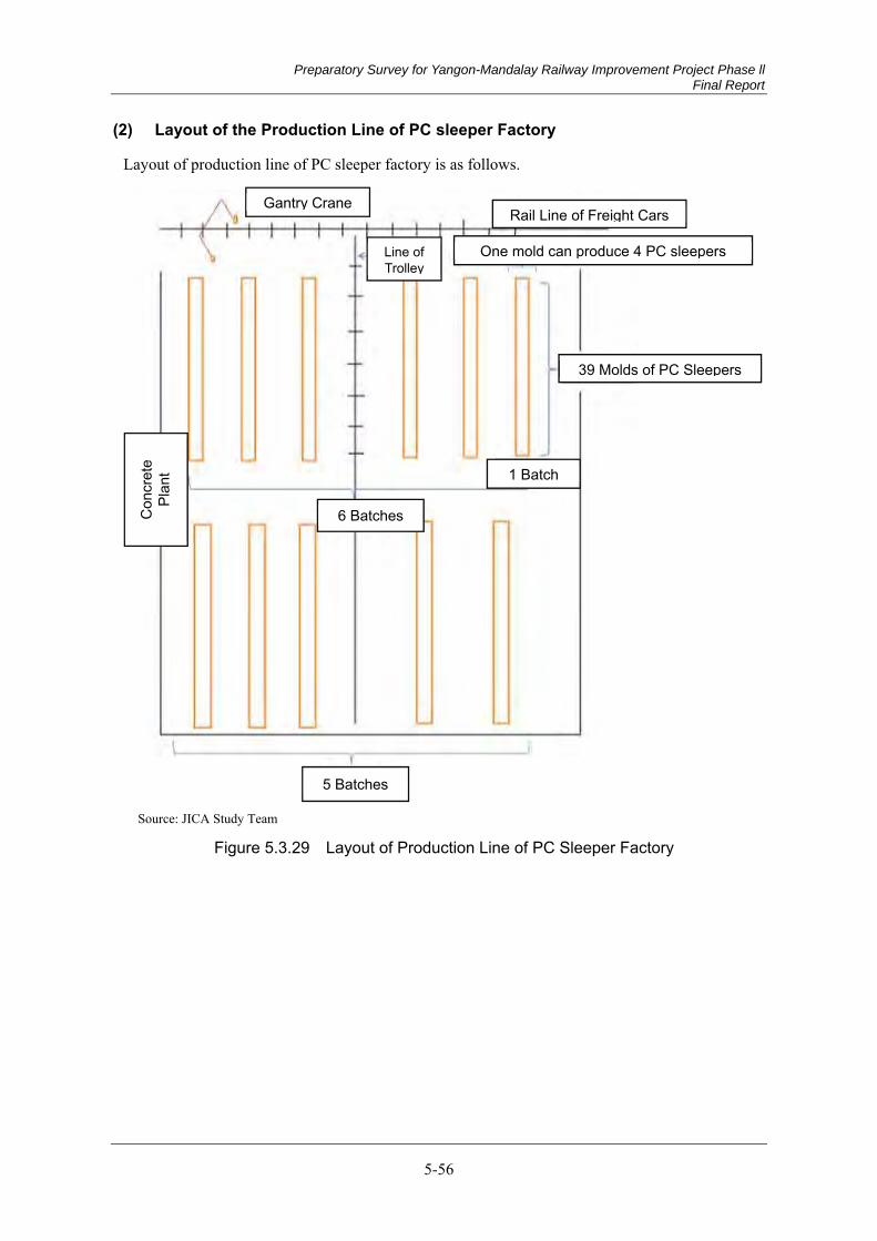
Preparatory Survey for Yangon-Mandalay Railway Improvement Project Phase ll Final Report
5-56
Layout of the Production Line of PC sleeper Factory (2)
Layout of production line of PC sleeper factory is as follows.
Source: JICA Study Team
Figure 5.3.29 Layout of Production Line of PC Sleeper Factory
Rail Line of Freight Cars
One mold can produce 4 PC sleepers
39 Molds of PC Sleepers
5 Batches
6 Batches
Line of Trolley
Con
cret
e Pl
ant 1 Batch
Gantry Crane

Preparatory Survey for Yangon-Mandalay Railway Improvement Project Phase ll Final Report
5-57
Production Cycle (3)
Production cycle of PC sleepers is shown as follows.
Tightening of PC steel strands
Building up mold of PC sleeper
Placing concrete into mold Removal of molds
Cutting of PC steel strands
24 hours 24 hours 24 hours
* (Preparation works for next cycle)
* (Preparation works for next cycle) : Cleaning molds, Cutting PC steel strands, Building up the mold of PC sleeper, Assembling the reinforce steel bars
Source: JICA Study Team
Figure 5.3.30 Production Cycle of PC Sleeper (1)
No.1 batch
2 days 1day 2 days 1day
No.2 batch
2days 1days 2 days
No.3 batch
2 days
Source: JICA Study Team
Figure 5.3.31 Production Cycle of PC Sleeper (2)
Note : Placing : Placing concrete into molds Removal : Removal of molds
Placing Placing Removal Removal
Placing Placing Removal Removal
Placing Removal Removal Placing Removal Placing

Preparatory Survey for Yangon-Mandalay Railway Improvement Project Phase ll Final Report
5-58
Production Capacity (4)
The project period is 2.5 years including preparation period of 0.5 years. As the result, the net construction period is 2 years. The production capacity of the 5 factories in the 2 years is expected to be produced 1,400,000 PC sleepers. This quantity can meet 1,350,000 which is necessary number for rehabilitation project between Taungoo and Mandalay. Detail is following.
The number of sleeper produced by one concrete placing:
39 molds/batch 4 PC sleepers/mold=1,716 PC sleepers
The rotation number of 1 batch:
3days cycle
The average production capacity per day of 1 factory:
1,716 1/3 = 572 PC sleepers
The annual rate of operation of factory:
0.67
The annual production capacity per 1 factory:
572*365*0.67 = 140,000 PC sleepers
The period of the production of PC sleepers:
2.5 years - (preparation period) 0.5 years = 2 years
The production number of PC sleeper per 1 factory in 2 years:
140,000/year 2 years = 280,000 PC sleepers
Production capacity of 5 factories in 2 years :
280.000/factory 5 factories = 1,400,000 PC sleepers
Necessary number of PC sleepers for the project:
1,350,000 PC sleepers
The production capacity of 5 factories in 2 years of production period satisfies necessary number for the project: 1,400,000> 1,350,000
Transportation Capacity of PC Sleepers (5)
1) Transportation by Freight Trains
The weight of one PC sleeper is approximately 200 kg, and the loading capacity of one freight car is 30tons. As the result, 150 PC sleepers can be loaded on one freight car. If one train consists of 10 freight cars, 1,500 PC sleepers can be transported only one train. As the production capacity of one factory per day is 572 pcs, the capacity of freight train transportation is enough.
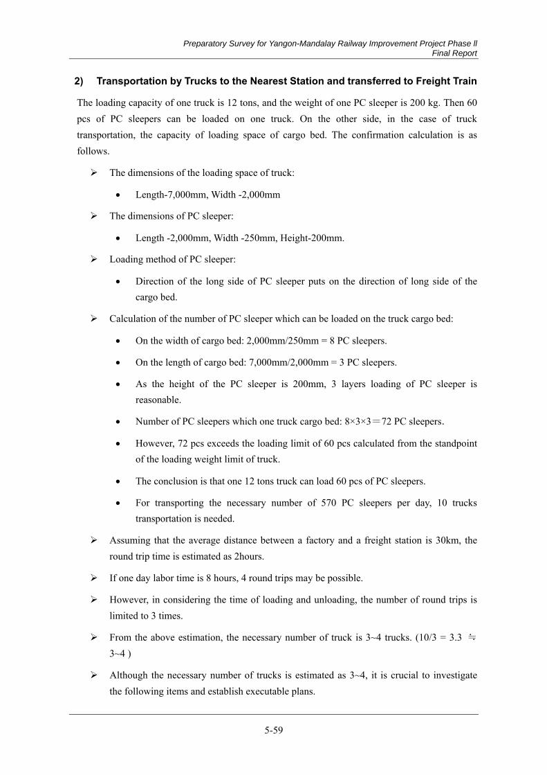
Preparatory Survey for Yangon-Mandalay Railway Improvement Project Phase ll Final Report
5-59
2) Transportation by Trucks to the Nearest Station and transferred to Freight Train
The loading capacity of one truck is 12 tons, and the weight of one PC sleeper is 200 kg. Then 60 pcs of PC sleepers can be loaded on one truck. On the other side, in the case of truck transportation, the capacity of loading space of cargo bed. The confirmation calculation is as follows.
The dimensions of the loading space of truck:
Length-7,000mm, Width -2,000mm
The dimensions of PC sleeper:
Length -2,000mm, Width -250mm, Height-200mm.
Loading method of PC sleeper:
Direction of the long side of PC sleeper puts on the direction of long side of the cargo bed.
Calculation of the number of PC sleeper which can be loaded on the truck cargo bed:
On the width of cargo bed: 2,000mm/250mm = 8 PC sleepers.
On the length of cargo bed: 7,000mm/2,000mm = 3 PC sleepers.
As the height of the PC sleeper is 200mm, 3 layers loading of PC sleeper is reasonable.
Number of PC sleepers which one truck cargo bed: 8×3×3=72 PC sleepers.
However, 72 pcs exceeds the loading limit of 60 pcs calculated from the standpoint of the loading weight limit of truck.
The conclusion is that one 12 tons truck can load 60 pcs of PC sleepers.
For transporting the necessary number of 570 PC sleepers per day, 10 trucks transportation is needed.
Assuming that the average distance between a factory and a freight station is 30km, the round trip time is estimated as 2hours.
If one day labor time is 8 hours, 4 round trips may be possible.
However, in considering the time of loading and unloading, the number of round trips is limited to 3 times.
From the above estimation, the necessary number of truck is 3~4 trucks. (10/3 = 3.3 ≒ 3~4 )
Although the necessary number of trucks is estimated as 3~4, it is crucial to investigate the following items and establish executable plans.

Preparatory Survey for Yangon-Mandalay Railway Improvement Project Phase ll Final Report
5-60
(1) To investigate the truck operation routes, and to find better choices.
(2) To negotiate freight train arrangement with MR for seeking smooth unloading and loading between truck and train.
Study from Technical Point of View (6)
1) Current Condition
High-early-strength Portland cement is used.
Ordinary curing system is applied and steam curing system is not applied
Myitnge factory applies curing system in the water pool.
Almost all such facilities as PC strand steel wire cutter, jacks for straining PC strand steel wire, PC sleeper testing equipment are China made, including concrete plants.
PC steel strand wire is used except Khin-U factory. At Khin-U factory, they have used single PC steel wire, but they plan to change them to strand steel wire.
The area of Myitnge factory is 14.25 acres (≒58,000m2), and other factories are rather larger than Myitnge factory.
Myitnge factory is old and has renewal plan. But there is no renewal plan at other factories, as they have no space to construct new facilities.
As Khin-U factory was established in 2010 and Pokakku factory was established in 2009, these factories are relatively new.
The number of employees of the Khin-U factory is 90-100. Other factories are in similar size of employees.
The life cycle of one PC sleeper mold is 450 times.
Loading test is carried out on 3 PC sleepers per one batch (156 PC sleepers= 39 molds/batch×4 PC sleepers/mold).
When one rejected PC sleeper is found in a loading test, the rejected PC sleeper is thrown away and the remains of the same batch are examined by hammer test.
In KenWoo factory, new PC sleeper molds for JIS 50N rails were already imported from China and are piled up in the factory.
Hand vibrator is used for compacting concrete in mold at all factories. Mold vibrator is not used.
The slump of concrete is 30~50mm and the concrete is solid cream concrete. The largest dimension of coarse aggregate is 20mm, and 8mm, 12mm and18mm aggregates are mixed.
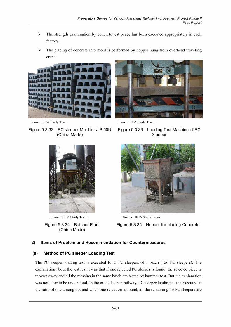
Preparatory Survey for Yangon-Mandalay Railway Improvement Project Phase ll Final Report
5-61
The strength examination by concrete test peace has been executed appropriately in each factory.
The placing of concrete into mold is performed by hopper hung from overhead traveling crane.
Source: JICA Study Team Source: JICA Study Team
Figure 5.3.32 PC sleeper Mold for JIS 50N (China Made)
Figure 5.3.33 Loading Test Machine of PC Sleeper
Source: JICA Study Team Source: JICA Study Team
Figure 5.3.34 Batcher Plant (China Made)
Figure 5.3.35 Hopper for placing Concrete
2) Items of Problem and Recommendation for Countermeasures
(a) Method of PC sleeper Loading Test
The PC sleeper loading test is executed for 3 PC sleepers of 1 batch (156 PC sleepers). The explanation about the test result was that if one rejected PC sleeper is found, the rejected piece is thrown away and all the remains in the same batch are tested by hammer test. But the explanation was not clear to be understood. In the case of Japan railway, PC sleeper loading test is executed at the ratio of one among 50, and when one rejection is found, all the remaining 49 PC sleepers are

Preparatory Survey for Yangon-Mandalay Railway Improvement Project Phase ll Final Report
5-62
thrown away. Recommendation is that the reliability of the hummer test is necessary to be confirmed, and if the reliability is confirmed, manual of the hummer test method should be made. The text of the manual is to be distributed to all the factories with providing the instruction course at the factories for requiring performing distinctly the test at the sites.
(b) Protection of Both Sides Surfaces of PC Sleeper
The both side’s surfaces of PC sleeper are not protected, and the cutting edges of PC steel strand wires are exposed. For preventing steel strand wires from rust and giving damage other items, it is needed to protect them with cement mortar etc.
Source: JICA Study Team
Figure 5.3.36 Side Surfaces of Finished PC Sleepers
(c) Applying Mold Vibrator
At present, hand vibrator is used to compact the concrete in the mold. It is recommended to try to use and find the superiority of mold vibrator.
(d) Steam Curing
It is recommendable to try to use steam curing.
(e) Checking the Supporting Deck of PC Sleeper Molds
It was explained at a factory that mold supporting decks have never been checked their irregularity of alignment and horizontality since the establishment. It is recommended to check mold supporting decks at all the factories before large quantity of PC sleeper production.
(f) Storage of finished PC Sleeper
It was observed that finished PC sleepers were piled up 13 layers high at the maximum, and some of the piles lean to one side. It is recommended to make manuals how to store finished PC sleepers. The manuals should be distributed to all the factories with the instruction to keep strictly to the manuals. The indication of appropriate supporting points is in particular important.
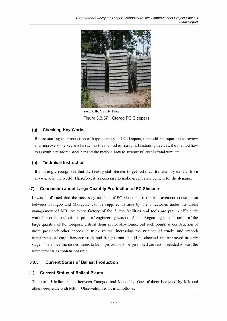
Preparatory Survey for Yangon-Mandalay Railway Improvement Project Phase ll Final Report
5-63
Source: JICA Study Team
Figure 5.3.37 Stored PC Sleepers
(g) Checking Key Works
Before starting the production of large quantity of PC sleepers, it should be important to review and improve some key works such as the method of fixing rail fastening devices, the method how to assemble reinforce steel bar and the method how to arrange PC steel strand wire etc.
(h) Technical Instruction
It is strongly recognized that the factory staff desires to get technical transfers by experts from anywhere in the world. Therefore, it is necessary to make urgent arrangement for the demand.
Conclusion about Large Quantity Production of PC Sleepers (7)
It was confirmed that the necessary number of PC sleepers for the improvement construction between Taungoo and Mandalay can be supplied in time by the 5 factories under the direct management of MR. At every factory of the 5, the facilities and tools are put in efficiently workable order, and critical point of engineering was not found. Regarding transportation of the large quantity of PC sleepers, critical items is not also found, but such points as construction of more pass-each-other spaces in truck routes, increasing the number of trucks and smooth transference of cargo between truck and freight train should be checked and improved in early stage. The above mentioned items to be improved or to be promoted are recommended to start the arrangements as soon as possible.
Current Status of Ballast Production 5.3.5
Current Status of Ballast Plants (1)
There are 5 ballast plants between Taungoo and Mandalay. One of them is owned by MR and others cooperate with MR. Observation result is as follows.
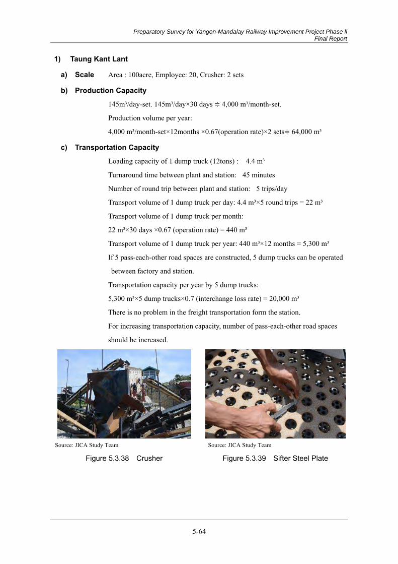
Preparatory Survey for Yangon-Mandalay Railway Improvement Project Phase ll Final Report
5-64
1) Taung Kant Lant
a) Scale Area : 100acre, Employee: 20, Crusher: 2 sets
b) Production Capacity
145m³/day-set. 145m³/day×30 days ≑ 4,000 m³/month-set.
Production volume per year:
4,000 m³/month-set×12months ×0.67(operation rate)×2 sets≑ 64,000 m³
c) Transportation Capacity
Loading capacity of 1 dump truck (12tons) : 4.4 m³
Turnaround time between plant and station: 45 minutes
Number of round trip between plant and station: 5 trips/day
Transport volume of 1 dump truck per day: 4.4 m³×5 round trips = 22 m³
Transport volume of 1 dump truck per month:
22 m³×30 days ×0.67 (operation rate) = 440 m³
Transport volume of 1 dump truck per year: 440 m³×12 months = 5,300 m³
If 5 pass-each-other road spaces are constructed, 5 dump trucks can be operated
between factory and station.
Transportation capacity per year by 5 dump trucks:
5,300 m³×5 dump trucks×0.7 (interchange loss rate) = 20,000 m³
There is no problem in the freight transportation form the station.
For increasing transportation capacity, number of pass-each-other road spaces
should be increased.
Source: JICA Study Team Source: JICA Study Team
Figure 5.3.38 Crusher Figure 5.3.39 Sifter Steel Plate
Preparatory Survey for Yangon-Mandalay Railway Improvement Project Phase ll Final Report
5-65
Source: JICA Study Team Source: JICA Study Team
Figure 5.3.40 Quarry Figure 5.3.41 Road Condition
2) Thent Sin Auna
a) Scale Adjacent to Bellin Station
Crusher: 6 sets (China and Myanmar made)
Material stone is transported from Sone10km far from the plant.
b) Production Capacity
Production capacity of 1 set of crusher: 135m³/day-set.
Production capacity of 6 sets of crushers: 324m³/day-6 sets.
Production capacity per month: 324m³/day ×30 days =9,720 m³/month
Production capacity per year:
9,720 m³/month×12months ×0.67(operation rate) ≑ 78,000 m³
c) Transportation Capacity
All the volume is transported by freight.
Load capacity of 30t hoper car: 11 m³
Load capacity of 1 train of 30 hoper cars: 11 m³×30 cars= 330 m³
Production capacity per day of 324 m³ is within the capacity of transportation.
Source: JICA Study Team
Figure 5.3.42 Crusher Plant adjacent Station
Preparatory Survey for Yangon-Mandalay Railway Improvement Project Phase ll Final Report
5-66
3) Htone Bo
a) Scale Owned by MR.
Crusher-2sets (Japan and India made)
b) Production Capacity
Production capacity per year of 1 set of crusher: 19,000~20,000 m³/year
Production capacity per year of 2 sets of crushers: 38,000~40,000 m³/year
c) Transportation Capacity
All the volume is transported by freight train.
Source: JICA Study Team Source: JICA Study Team
Figure 5.3.43 Crusher Figure 5.3.44 Quarry
4) Taunh Be Lar
a) Scale As vast as 700 acre (300ha) property
Crusher-8 sets
400 Employees
b) Production Capacity
Production capacity per hour of 2 sets of crushers among 8 sets:
50 t/h-set ×2 sets = 100t/h・2sets = 37m³/h・2sets
Production capacity per hour of 6 sets of crushers among 8 sets:
25 t/h-set ×6 sets = 150t/h・6sets = 56m³/h・6 sets
Production capacity per day of all the 8 sets of crushers:
(37+56=93m³)×8 hours =744m³/day-8 sets
Production capacity per year of all the 8 sets of crushers:
744m³/day×365days×0.67(operation rate) = 180,000 m³/year-8sets
(Note) However, as there was found unclear explanation at the survey, detail investigation is necessary.
Preparatory Survey for Yangon-Mandalay Railway Improvement Project Phase ll Final Report
5-67
c) Transportation Capacity
As the width of the 11 miles (17.6 km) road between the plant and Yae Ni Station is wide enough for truck transportation, product transportation capacity can be increased fit for the production volume. However, as the road condition is very rough, the improvement of the road condition on detail investigation should be necessary.
Source: JICA Study Team Source: JICA Study Team
Figure 5.3.45 Crusher Figure 5.3.46 Quarry
5) Taungoo
a) Scale As vast as 345 acre (148 ha) property.
Crusher-10 sets (all the 10 sets are china made).
1,000 employees
The plant is expected to be used for Phase-1 construction.
b) Production Capacity
Production capacity per year of 1 set of crusher:
80 t/day-set = 30 m³/day-set = 900 m³/month-set ≑ 7,000 m³/year
(considering 0.67 operation rate)
Production capacity per year of 10 sets of crushers: 70,000 m³/year-10 sets
c) Transportation Capacity
As the product is transported by truck on the 6.4 km road to Taungoo Station, and transferred to freight train, problems of transportation may not be found. However, the improvement of the road condition on detail investigation should be necessary.

Preparatory Survey for Yangon-Mandalay Railway Improvement Project Phase ll Final Report
5-68
Summary of the Survey on Ballast Supply Status and Study Items (2)
The summary of the survey on ballast supply status of 5 ballast plants between Taungoo and Mandalay is shown in Table 5.3.8.
Table 5.3.8 Current Status of Ballast Production Capacity
Plant Name Production Capacity per Year
Transportation Capacity per Year
Means of Transportation
Taung Kant Lant 64,000m³ 20,000m³ Truck & Rail
Bellin Station 78,000m³ more than 78,000m³ Rail Htone Bo 40,000m³ more than 40,000m³ Rail
Taunh Be Lar 180,000m³
(Detail investigation is necessary)
180,000m³(Detail investigation is
necessary)Truck & Rail
Taungoo 70,000m³ 70,000m³
(Detail investigation is necessary)
Truck & Rail
Total 432,000m³ 388,000m³ Source: JICA Study Team
As shown above, the total capacity of ballast production per year of the 5 plants is 432,000 m³. The net construction period is 3 years, which is added 0.5 years as preparation period from the gross construction period of 2.5 years. The expected volume of ballast production of the 3 years is expected to be 1,296,000 m³.
On the other side, as the necessary ballast volume for the Phase-2 construction is 1,200,000 m³, it is enough ballast supply volume. To be taken the consideration, as the last one year of Phase-1 construction period is overlapped with the first one year construction of Phase-2, it is necessary enough volume of ballast in advance.
In case it becomes shortage of ballast, it is important to confirm if the quality of the ballast is fit for MR standard and if their cooperation is reliable of third partiy plant. And, if the cooperation is established, the ballast from 5 MR plants is mixed with the ballast from the plants of the third parties, it is necessary to establish the ways of control both of the quality and the supply execution.
About the capacity of transportation, the transportation volume is slightly shortage at the current status, it is necessary to consider increasing transportation capacity. About the truck transportation of Taunng Kant Lant Plant, to increase truck pass-each-other road spaces is especially important, and the construction should be executed on detailed survey.
The quality of the ballast of each plant is acceptable enough. The hardness is enough, and smooth or flat surface stones were not found in the investigation. The sample test result of Taunng Kant Lant Plant is shown in Figure 5.3.47.

Preparatory Survey for Yangon-Mandalay Railway Improvement Project Phase ll Final Report
5-69
Source: JICA Study Team
Figure 5.3.47 Ballast Sample Test Certificate of Taunng Kant Lant Plant
Summary of Quantity and Cost of Track Works 5.3.6
The summary of material & machinery and cost of track works is shown in Table 5.3.9.
Preparatory Survey for Yangon-Mandalay Railway Improvement Project Phase ll Final Report
5-70
Table 5.3.9 Summary of Quantity and Cost of Track Works
Source: JICA Study Team
Taungoo 267.2 Naypyidaw 370.0 Ingyinkan 448.0 Kumelan 549.5
Naypyidaw 370.0 Ingyinkan 448.0 Kumelan 549.5 Mandalay 620.5
353.3 km Distance 102.8 Diatance 78.0 Distance 101.5 Distamce 71.0
1. Rail 50N ton 73,663 21,418 16,194 20,960 15,091 8,620 8,620 -
2. Rail 37kg ton 3,663 635 244 830 1,954 - - -
3. Track Laying km 707 206 171 205 125 1,256 - 15,361
#8.5 50N set 181 51 31 42 57 1,236 1,158 941
#12 50N set 272 74 72 55 71 2,019 1,904 1,414
Scissors set 8 3 0 4 1 256 240 187
set 490 139 103 115 133 217 - 2,647
6. Buffer Rail set 136 38 41 28 29 54 54 -
7. Compromise Rail unit 40 6 9 6 19 14 14 -
8. PC Sleeper (50N) millionpcs 1.35 0.38 0.31 0.39 0.27 717 - 8,780
pc 12,896 3,120 2,626 3,562 3,588 516 516 -
millionpcs 0.176 - - 458 458 -
pc 156 - - 187 187 -
m3 18,600 - 9,300 - 9,300 4 - 37
13. Track Works Depot location 4 1 1 1 1 16 - 200
14. Machinery - -
(1) MTT unit 4 1,440 1,440 -
unit 4 440 440 -
unit 4 200 200 -
unit 3 120 120 -
unit 40 12 12 -
(6) Gantry Crane (2t) unit 47 47 47 -
unit 1 60 60 -
2,319 2,319 -
17,889 15,470 29,567
Taungoo 267.2 Naypyidaw 370.0 Ingyinkan 448.0 Kumelan 549.5
Naypyidaw 370.0 Ingyinkan 448.0 Kumelan 549.5 Mandalay 620.5
353.3 km Distance 102.8 Diatance 78.0 Distance 101.5 Distamce 71.0
Ballast millionm3
1.20 0.35 0.27 0.34 0.24
Sub Ballast millionm3
1.64 0.49 0.38 0.44 0.33
Cost
Breakdown of Total Cost
Total(million Yen) Yen
(million Yen)Kyat
(million Kyat)
10. FD Clip(including insulation clip) 0.176
Item
CP 204CP 203CP 202
Quantity
(Km Post) km (Km Post) km (Km Post) km (Km Post) km
Workinng SectionTotal
(Km Post) km (Km Post) km
Total Distancebetw eenTaungoo andMandalay
CP 201
Unit
Reference: ( Total Cost of Machinery)
TOTAL
4. Turnout
(2) Flash Butt WeldingMachine
(3) Portable gasPressure WeldingMachine
(4) Track MeasuringMachine
(5) Portable GanrtyCrane for 200m RailRenewal Site
(7) Wagon for carring200m Long Rail
12. Concrete Roadbed ofNaypyidaw St. andMandalay St.
5. Turnout Tamping(1 set=3 times tampings)
9. Synthetic Sleeper(for turnout)
(Km Post) km (Km Post) km
11. Mould for FD ClipSleeper 156
[Note-1]The item of "(3)Track Laying" includes such 6 items as follows in figures in lumps :(1) Ballast, (2) Renewal of Rail, (3) Track Tamping by MTT (3 times), (4) Rail Flash Butt Welding, (5) Rail Gas Welding, (6) Fish Plate
[Note-2]However, as " Ballast " and " Sub Ballast " are the major materials of track & civil works, the estimation of necessary volume of the 2 materials is shown in the following table. Thefigures of [Sub Ballast] are to be added up in Civil Works Quantity & Cost.
CP 203 CP 204
Item
Quantity
Unit
TotalWorkinng Section
CP 201 CP 202
Total Distancebetw eenTaungoo andMandalay
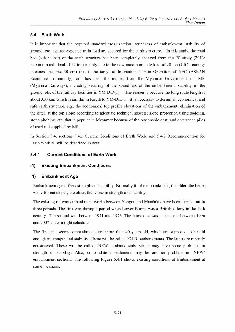
Preparatory Survey for Yangon-Mandalay Railway Improvement Project Phase ll Final Report
5-71
5.4 Earth Work
It is important that the required standard cross section, soundness of embankment, stability of ground, etc. against expected train load are secured for the earth structure. In this study, the road bed (sub-ballast) of the earth structure has been completely changed from the FS study (2013: maximum axle load of 17 ton) mainly due to the new maximum axle load of 20 ton (UIC Loading: thickness became 30 cm) that is the target of International Train Operation of AEC (ASEAN Economic Community), and has been the request from the Myanmar Government and MR (Myanma Railways), including securing of the soundness of the embankment, stability of the ground, etc. of the railway facilities in YM-D/D(1). The reason is because the long route length is about 350 km, which is similar in length to YM-D/D(1), it is necessary to design an economical and safe earth structure, e.g., the economical top profile elevations of the embankment; elimination of the ditch at the top slope according to adequate technical aspects; slope protection using sodding, stone pitching, etc. that is popular in Myanmar because of the reasonable cost; and deterrence piles of used rail supplied by MR.
In Section 5.4, sections 5.4.1 Current Conditions of Earth Work, and 5.4.2 Recommendation for Earth Work all will be described in detail.
Current Conditions of Earth Work 5.4.1
Existing Embankment Conditions (1)
1) Embankment Age
Embankment age affects strength and stability. Normally for the embankment, the older, the better, while for cut slopes, the older, the worse in strength and stability.
The existing railway embankment works between Yangon and Mandalay have been carried out in three periods. The first was during a period when Lower Burma was a British colony in the 19th century. The second was between 1971 and 1973. The latest one was carried out between 1996 and 2007 under a tight schedule.
The first and second embankments are more than 40 years old, which are supposed to be old enough in strength and stability. These will be called ‘OLD’ embankments. The latest are recently constructed. These will be called ‘NEW’ embankments, which may have some problems in strength or stability. Also, consolidation settlement may be another problem in ‘NEW’ embankment sections. The following Figure 5.4.1 shows existing conditions of Embankment at some locations.
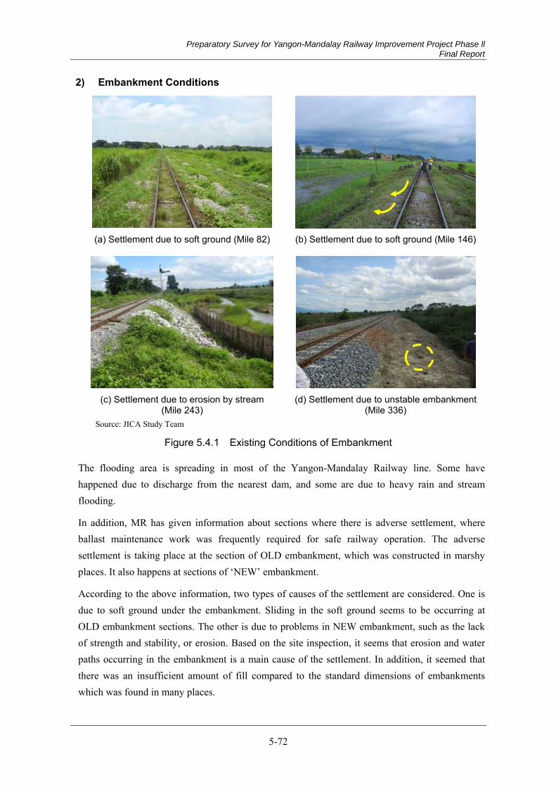
Preparatory Survey for Yangon-Mandalay Railway Improvement Project Phase ll Final Report
5-72
2) Embankment Conditions
(a) Settlement due to soft ground (Mile 82) (b) Settlement due to soft ground (Mile 146)
(c) Settlement due to erosion by stream (Mile 243)
(d) Settlement due to unstable embankment (Mile 336)
Source: JICA Study Team
Figure 5.4.1 Existing Conditions of Embankment
The flooding area is spreading in most of the Yangon-Mandalay Railway line. Some have happened due to discharge from the nearest dam, and some are due to heavy rain and stream flooding.
In addition, MR has given information about sections where there is adverse settlement, where ballast maintenance work was frequently required for safe railway operation. The adverse settlement is taking place at the section of OLD embankment, which was constructed in marshy places. It also happens at sections of ‘NEW’ embankment.
According to the above information, two types of causes of the settlement are considered. One is due to soft ground under the embankment. Sliding in the soft ground seems to be occurring at OLD embankment sections. The other is due to problems in NEW embankment, such as the lack of strength and stability, or erosion. Based on the site inspection, it seems that erosion and water paths occurring in the embankment is a main cause of the settlement. In addition, it seemed that there was an insufficient amount of fill compared to the standard dimensions of embankments which was found in many places.
Preparatory Survey for Yangon-Mandalay Railway Improvement Project Phase ll Final Report
5-73
At Mile 357, stone pitching was found to be constructed in the latest embankment period. MR stated that the stone pitching was a countermeasure that was constructed to prevent erosion and adverse settlement. At present, there is no adverse settlement even in the rainy season.
The following Figure 5.4.2 and Figure 5.4.3 show lack of fill in the embankment and stone pitching to prevent erosion respectively.
See Appendix 5.4.1.
Source: JICA Study Team
Figure 5.4.2 Lack of fill in the embankment (Mile 44)
Source: JICA Study Team
Figure 5.4.3 Stone pitching to prevent erosion (Mile 357)
3) Geotechnical Surveys
Two types of geotechnical investigations had been carried out during the Feasibility Study (FS) stage between Yangon and Mandalay. There were one bored hole and fourteen hand auger (HA) holes between Taungoo and Mandalay. The bored hole was mainly to take N values in the original ground in order to identify geotechnical characteristics, especially potential landslides and consolidation settlement due to soft ground. The hand auger holes were to take cone resistance values in order to get bearing capacity of the existing embankment.
See Appendix 5.4.1.
4) Landslide and Consolidation Settlement
Based on geotechnical surveys during the YM-F/S stage, soft soil is normally defined as cohesive soil (clay or silt) that has less than 5 in N value. The bored hole at Mile 104 has a 6-meter thick silt layer SPT 3 to 4 between GL(Ground Level)-8.5m and -14.5m. This layer has many seam layers of sand, and consolidation settlement may occur in a very short time during embankment work. It may be assumed that adverse settlement may not happen for a long time. And in the case of up to 3-meter embankment height, landslides may not occur. The other six bored holes don’t have the same kind of soft layer. Therefore, there is low risk of landslide and adverse settlement in less than 3-meter-high embankments in the bored hole locations where the JICA Study Team of YM-F/S has investigated between Yangon and Mandalay.
Preparatory Survey for Yangon-Mandalay Railway Improvement Project Phase ll Final Report
5-74
There were some places where the cohesive soil N values were found to be from 0 to 3 in the geological survey of the YM-D/D (1) study at the sites. The embankments are stabilized as it has been more than 40 years since construction. Because there were no deformed embankments found in the topographical and alignment surveys, the risk, e.g., landslide or lateral flow of the embankment is small if no additional embankment is constructed. Therefore, it is not necessary to carry out any counter measures.
JST suggests that effective geo surveys should be carried out during D/D stage at the following locations even referring to the above information in other studies.
the up&down line (Mile 184/15- 185/05)
the down line (Mile 199/14-18)
the up line (Mile 216/23-24),
the down line (Mile 220/16-17, 218/21-22, 218/14-16)
5) Bearing Capacity of Embankments
Based on the results of the hand auger investigation at YM-F/S stage, the bearing capacity for the investigated location has been calculated for the embankments. Railway loading is distributed to the embankment through the ballast layer. The distributed loading is critical at the top portion of the embankments. The stress on the existing roadbed has been checked with the allowable bearing capacity from the hand auger investigations.
All allowable bearing capacities were more than the calculated distribution loading. Therefore, all embankment structures were adequate in bearing capacity near the locations where HA investigations had been carried out at YM-F/S stage.
However, some upper layers of the embankments were found that have insufficient strength. Therefore, the YM-D/D (1) study team proposed that the investigation/inspection of the bearing capacity of the ground and each additional layer at the site should be carried out. It is also necessary to incorporate this testing requirement in the tender documents in YM phase II project.
Problems for Safe & High Speed Operation (2)
1) Lack of Fill
The first problem is the lack of fill compared to the standard formation, which was agreed between MR and the Study Team. These types of embankments were found in many locations during site inspection. The following Figure 5.4.4 shows standard formation for Single and Double lines.
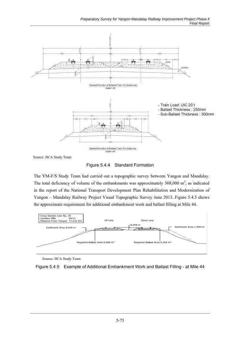
Preparatory Survey for Yangon-Mandalay Railway Improvement Project Phase ll Final Report
5-75
Source: JICA Study Team
Figure 5.4.4 Standard Formation
The YM-F/S Study Team had carried out a topographic survey between Yangon and Mandalay. The total deficiency of volume of the embankments was approximately 368,000 m3, as indicated in the report of the National Transport Development Plan Rehabilitation and Modernization of Yangon – Mandalay Railway Project Visual Topographic Survey June 2013. Figure 5.4.5 shows the approximate requirement for additional embankment work and ballast filling at Mile 44.
Source: JICA Study Team
Figure 5.4.5 Example of Additional Embankment Work and Ballast Filling - at Mile 44
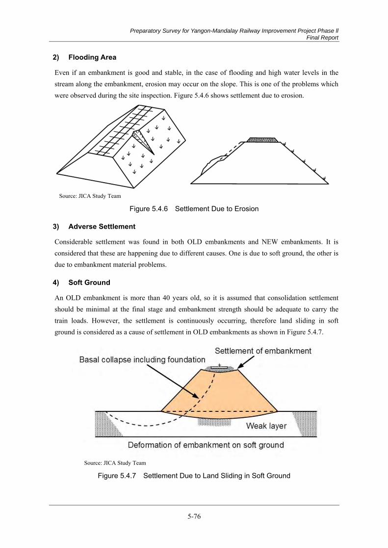
Preparatory Survey for Yangon-Mandalay Railway Improvement Project Phase ll Final Report
5-76
2) Flooding Area
Even if an embankment is good and stable, in the case of flooding and high water levels in the stream along the embankment, erosion may occur on the slope. This is one of the problems which were observed during the site inspection. Figure 5.4.6 shows settlement due to erosion.
Source: JICA Study Team
Figure 5.4.6 Settlement Due to Erosion
3) Adverse Settlement
Considerable settlement was found in both OLD embankments and NEW embankments. It is considered that these are happening due to different causes. One is due to soft ground, the other is due to embankment material problems.
4) Soft Ground
An OLD embankment is more than 40 years old, so it is assumed that consolidation settlement should be minimal at the final stage and embankment strength should be adequate to carry the train loads. However, the settlement is continuously occurring, therefore land sliding in soft ground is considered as a cause of settlement in OLD embankments as shown in Figure 5.4.7.
Source: JICA Study Team
Figure 5.4.7 Settlement Due to Land Sliding in Soft Ground

Preparatory Survey for Yangon-Mandalay Railway Improvement Project Phase ll Final Report
5-77
5) Embankment Material Problem
NEW embankment was constructed under the tight schedule and it is assumed that material selection for embankment might not be properly done, so embankment may be easy to have erosion on slope by heavy rain. This problem can be obviously understood from Figure 5.4.1(d) and Figure 5.4.6. ent.
Recommendation for Earth Work 5.4.2
Earthworks to the Standard Formation (1)
For safe and high-speed railway operation, firstly, embankment dimensions should be kept at least to the standard formation which has been agreed between MR and the JICA Study Team as indicated in Chapter 4. These earthworks, including trimming slope and backfilling, should be carried out prior to other rehabilitation measures, such as stone pitching and preventive pile installation. Also, selected suitable material should be utilized for the backfilling. After completion of backfilling work, slope protection should be provided.
Figure 5.4.8 shows Additional Embankment Work at Mile 44.
Source: JICA Study Team
Figure 5.4.8 Additional Embankment Work at Mile 44
Stone Pitching for Flooding Protection (2)
Stone pitching is common in Myanmar and has already been carried out at Mile 357 (upline). It was heard from MR that adverse settlement has never been recorded in this area since the construction of the stone pitching.
A gravel layer and PVC(polyvinyl chloride)pipe also need to be provided for drainage. Geotextile should cover the side of the embankment for separation between gravel and soil.
Figure 5.4.9 shows the details of the method and construction sequence.
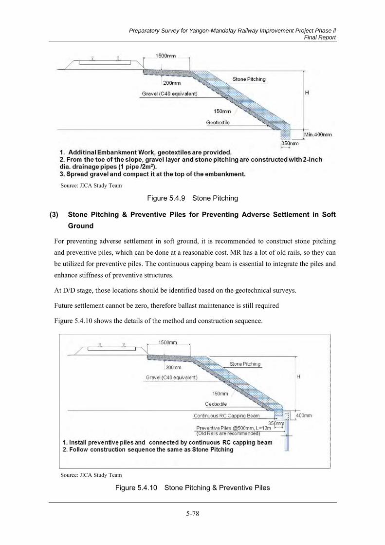
Preparatory Survey for Yangon-Mandalay Railway Improvement Project Phase ll Final Report
5-78
Source: JICA Study Team
Figure 5.4.9 Stone Pitching
Stone Pitching & Preventive Piles for Preventing Adverse Settlement in Soft (3)Ground
For preventing adverse settlement in soft ground, it is recommended to construct stone pitching and preventive piles, which can be done at a reasonable cost. MR has a lot of old rails, so they can be utilized for preventive piles. The continuous capping beam is essential to integrate the piles and enhance stiffness of preventive structures.
At D/D stage, those locations should be identified based on the geotechnical surveys.
Future settlement cannot be zero, therefore ballast maintenance is still required
Figure 5.4.10 shows the details of the method and construction sequence.
Source: JICA Study Team
Figure 5.4.10 Stone Pitching & Preventive Piles
Preparatory Survey for Yangon-Mandalay Railway Improvement Project Phase ll Final Report
5-79
Raising Embankment (4)
At the YM-F/S stage, the raising embankment was not recommended between Taungoo and Mandalay due to flooding, but due to bridge raise up and replacement
The JST will study new flooding data from MR and bridge information, and recommend some portion of the raising embankment in YM phase II project if necessary.
Slope Protection for Normal Embankments (5)
In Myanmar, natural planting on embankment slopes seems to be relied upon. However, if a heavy rain fell just after embankment construction, erosion would occur and the specified dimensions of the embankment could not be maintained. Therefore, slope protection is important to prevent erosion on slopes for safe and high-speed railway train operation.
There are two methods, a turfing method and a hydro-seeding method, to be considered. The turfing method has been applied for this project based on availability in Myanmar and the economic point of view.
Summary of Outline Design for Earth Works (6)
MR has accepted the summary of outline design for earth worksshown in Appendix 5.4.2. This outline design concept is the same as that of YM Phase1.