preparation and characterization of bismuth oxide ... and characterization of bismuth oxide...
TRANSCRIPT

Pcb
AD
a
ARR1AA
KDHBMEH
1
iceaniaamiioc
0d
.com
.cn
Talanta 87 (2011) 15– 23
Contents lists available at SciVerse ScienceDirect
Talanta
j ourna l ho me page: www.elsev ier .com/ locate / ta lanta
reparation and characterization of bismuth oxide nanoparticles-multiwalledarbon nanotube composite for the development of horseradish peroxidaseased H2O2 biosensor
run Prakash Periasamy, Singying Yang, Shen-Ming Chen ∗
epartment of Chemical Engineering and Biotechnology, National Taipei University of Technology, No. 1, Section 3, Chung-Hsiao East Road, Taipei 106, Taiwan, ROC
r t i c l e i n f o
rticle history:eceived 24 July 2011eceived in revised form2 September 2011ccepted 13 September 2011vailable online 5 October 2011
eywords:irect electrochemistryorseradish peroxidasei2O3
ultiwalled carbon nanotubes
a b s t r a c t
In this work, preparation and characterization of a novel nanocomposite containing bismuth oxide (Bi2O3)nanoparticles and multiwalled carbon nanotubes (MWCNTs) was presented. Powder X-ray diffraction(XRD) studies revealed that as-synthesized Bi2O3 nanoparticles are crystalline and belong to �-phasewith monoclinic symmetry. Field emission scanning electron microscopy (FESEM) study results showedthat the size of Bi2O3 nanoparticles is 50 nm. Energy-dispersive X-ray (EDX) spectra of as-preparedBi2O3–MWCNT nanocomposite displayed characteristic Bi and C peaks which confirmed the incorpo-ration of Bi2O3 with MWCNT. The prepared Bi2O3–MWCNT was also characterized by scanning electronmicroscopy (SEM) and atomic force microscopy (AFM) studies. The direct electron transfer of horseradishperoxidase (HRP) has been revealed at Bi2O3–MWCNT modified glassy carbon electrode (GCE). In orderto firmly anchor the HRP molecules onto Bi2O3–MWCNT matrix, a thin layer of 1% nafion (NF) solutionwas coated as a binder. The fabricated NF/HRP/Bi2O3–MWCNT/GCE exhibits well defined quasi-reversible
0 ′
pm
lectrocatalysisydrogen peroxide
redox peaks at a formal potential (E ) of −0.326 V vs. Ag/AgCl reference electrode in 0.05 M phosphatebuffer solution (PBS), pH 7. NF/HRP/Bi2O3–MWCNT film remarkably lowers the over potential for H2O2
reduction than MWCNT, Bi2O3–MWCNT and unmodified GCEs. The proposed composite film exhibitsquick amperometric i–t response (5 s) towards H2O2 in the linear range of 8.34–28.88 mM with a sensi-tivity of 26.54 �A �M−1 cm−2. The developed NF/HRP/Bi2O3–MWCNT biosensor has a good operationalstability and high selectivity towards H2O2.
www.s
. Introduction
In recent years, owing to the large surface area, high mechan-cal resistance, and high electronic conductivity [1], multiwalledarbon nanotubes (MWCNTs) and their composites have beenxtensively used for biosensors [2], fuel cells [3], solar cells [4]nd photovoltaics [5] applications. MWCNT composites with metalanoparticles [6], metal oxide nanoparticles [7], and conduct-
ng polymers [8,9] have been widely employed for the sensitivend selective determination of essential compounds such asscorbic acid, epinephrine, uric acid, catechol and quinol. Since,etal oxides possess unique advantages such as high sensitiv-
ty, good selectivity and large surface-to-volume ratio, so farncreasing number of researchers have reported the production
f novel CNT–metal oxide nanocomposites for biosensors appli-ations [10,11]. MWCNT–metal oxide composites have also been∗ Corresponding author. Tel.: +886 2270 17147; fax: +886 2270 25238.E-mail address: [email protected] (S.-M. Chen).
039-9140/$ – see front matter © 2011 Elsevier B.V. All rights reserved.oi:10.1016/j.talanta.2011.09.021
© 2011 Elsevier B.V. All rights reserved.
employed in supercapacitors [12], electrochemical capacitors [13],and lithium ion batteries [14].
Bismuth oxide (Bi2O3) is a well known transition metal oxideand it has been intensively studied due to its interesting thermaland electrical transport properties [15]. Moreover, Bi2O3 nanoparti-cles can offer large surface area and good electrochemical stability.Recently Bi2O3 nanoparticles have attracted considerable attentiondue to their potential applications in electrochemical sensors forsensing zinc [16], paracetamol [17] and to probe DNA hybridization[18]. Owing to its unique properties such as nontoxic nature, excel-lent chemical inertness and biocompatibility, it has been employedas potential immobilizing platforms for glucose oxidase [19], andpolyphenol oxidase [20].
Hydrogen peroxide (H2O2) has received considerable attentionbecause of its good antiseptic and antibacterial property [21]. Dueto its excellent oxidizing and bleaching property, H2O2 has beenwidely employed in industries and clinical laboratories. Due to the
immense applications of H2O2, there is always a need for explor-ing a suitable, cost-effective, sensitive H2O2 quantification tool.The high specify of enzyme–substrate interactions with the usu-ally high turnover rates of biocatalysts, enzyme based biosensors
m
1 / Talan
hpwotmatatpohoacnnrmto
wtwmtwfihs
2
2
wVdLSecip0Nwui1a
2
Cce0dwt
nanoparticles are closely distributed throughout the film surface.The Bi2O3 nanoparticles are 50 nm in size. The large surface area andporous architecture of Bi2O3 nanoparticles can enhance the enzymeloading.
www.sp
6 A.P. Periasamy et al.
ave attracted significant attention these days [22]. Horseradisheroxidase (HRP) is an important heme containing redox enzymehich belongs to class III (classical secretory plant peroxidases)
f the plant peroxidase super family [23]. HRP contains ferripro-oporphyrin IX prosthetic group at its active centre. It has been
ajorly used in amperometric H2O2 biosensors due to its uniquebility to catalyze H2O2 reduction process at a specific low poten-ial via direct electron transfer [24]. Since, bare electrode lacks thebility to promote the direct electron transfer process; it necessi-ates exploring novel nanocomposites materials with substantialroperties to augment the electron transfer phenomena. Previ-us literature reports shows that direct electrochemistry of HRPas been revealed at CNTs [25,26] and metal oxides such as zincxide (ZnO) [27], titanium dioxide (TiO2) [28], mesoporous TiO2nd tin oxide (SnO2) [29], SnO2 nanorods [30], SiO2 nanoparti-les [31], nanostructured cerium oxide (CeO2) [32], nickel oxideanoparticles (NiO NPs) [33], polyquaternium–manganese oxideanosheets [34], and zirconia nanocomposites [35]. Recently, weeported the direct electrochemistry of HRP at RuO2 nanoparticlesodified GCE [36]. However, thorough view of literature reveals
hat no one has attempted to explore the direct electrochemistryf HRP at Bi2O3–MWCNT nanocomposite.
In this work, we prepared Bi2O3–MWCNT nanocomposite ande used it as a novel electrode material to explore the direct elec-
rochemistry of HRP. Bi2O3–MWCNT nanocomposite and HRP filmsere modified sequentially on a GCE surface by simple drop castingethod. In order to provide an outer protective coating as well as to
ightly anchor the HRP molecules a thin layer of nafion (NF) coatingas employed as a binder. The developed NF/HRP/Bi2O3–MWCNTlm exhibits excellent electrocatalytic activity towards H2O2 withigh sensitivity and selectivity. Moreover, the composite film pos-esses good biocompatibility and appreciable operational stability.
. Experimental
.1. Reagents
MWCNT with O.D. 10–15 nm, I.D. 2–6 nm and length 0.1–10 �mas obtained from Aldrich. Peroxidase, from horseradish, typeI-A was purchased from Sigma. Bismuth (III) nitrate pentahy-rate, 99.9% was obtained from Wako pure chemical Industries,td. Polyethylene glycol solution (PEG-4000) was purchased fromigma–Aldrich and used as received. 5 wt% NF perfluorinated ionxchange resin was purchased from Aldrich and the required NFoncentrations such as 0.25, 0.5, 0.75, 1.0 and 1.25% were preparedn definite volume of 95% pure ethanol, obtained from Shimakyu’sure chemicals. The supporting electrolyte used in this study was.05 M phosphate buffer solution (PBS), pH 7 prepared using 0.05 Ma2HPO4 and NaH2PO4 solutions. All the reagents used in this workere of analytical grade and all aqueous solutions were preparedsing doubly distilled water. Prior to each experiment, the exper-
mental solutions were deoxygenated with pre-purified N2 gas for0 min and the N2 tube was kept above the solutions to maintainn inert atmosphere.
.2. Apparatus
Cyclic voltammetry (CV) experiments were carried out usingHI 1205b work station. A conventional three electrode cellontaining freshly prepared 0.05 M PBS (pH 7) was used forlectrochemical studies. GCE with an electrode surface area of
.079 cm2 was used as working electrode. Pt wire with 0.5 mmiameter was used as counter electrode and all the potentialsere referred with respect to standard Ag/AgCl reference elec-rode. Amperometric (i–t curve) measurements were performed
.com
.cn
ta 87 (2011) 15– 23
using CHI-750 potentiostat with analytical rotator AFMSRX (PINEinstruments, USA). EIM6ex ZAHNER (Kroanch, Germany) was usedfor electrochemical impedance spectroscopy (EIS) studies. Surfacemorphological studies were carried out using Hitachi S-3000 Hscanning electron microscope (SEM) and Being nano-instrumentsCSPM 4000, atomic force microscope (AFM). Field emissionscanning electron microscope (FESEM), JSM-6500F was used toinvestigate the surface morphology of as-prepared Bi2O3 nanopar-ticles. Energy-dispersive X-ray (EDX) spectra was recorded usingHORIBA EMAX X-ACT (Model 51-ADD0009, Sensor + 24 V = 16 W,resolution at 5.9 keV = 129 eV). Powder X-ray diffraction (XRD)studies were performed in a XPERT-PRO (PANalytical B.V., TheNetherlands) diffractometer using Cu K� radiation (k = 1.54 A◦).UV–visible absorption spectroscopy measurements were carriedout using Hitachi U-3300 spectrophotometer.
2.3. Preparation and characterization of Bi2O3 nanoparticlesusing FESEM studies
Bi2O3 nanoparticles were prepared according to the proce-dure reported elsewhere in the literature [37]. Transparent Bi3+
aqueous solution was obtained by dissolving 0.05 mol Bi(NO3)3in 30 ml 0.05 M HNO3, to which 20 ml polyethylene glycol (PEG-4000) was added as dispersant. Then 50 ml of 4 M NaOH aqueoussolution was quickly poured into this solution with vigorousstirring, which immediately leads to the formation of yellow-ish precipitate. The whole reaction mixture was kept at 90 ◦Cand stirred continuously for 2 h. Then the as-produced precip-itates were filtered, washed with alcohol and doubly distilledwater for several times, and then dried at 60 ◦C in an air oven.Finally, faint yellowish Bi2O3 samples were obtained. Since theprepared Bi2O3 nanoparticles are sparingly soluble in water, wedispersed the accurately weighed quantities of Bi2O3 nanopar-ticles in DMF solution to obtain a final concentration of 1 mgml−1. The as-obtained Bi2O3/DMF dispersion was evenly spreadon a pre-cleaned indium tin oxide electrode (ITO) surface anddried well in an air oven to evaporate the solvent molecules.The prepared Bi2O3 nanoparticles coated ITO electrode was usedfor FESEM study. The FESEM image of the Bi2O3 nanoparticles at100 nm resolutions is shown in Fig. 1. The Bi2O3 nanoparticles pos-sess highly porous surface morphology. Spherical shaped Bi2O3
Fig. 1. FESEM image of Bi2O3 nanoparticles.

/ Talan
2
ntboiaBMc
2
pwaadrwod(ittptwsfifi
A.P. Periasamy et al.
.4. Preparation of Bi2O3–MWCNT nanocomposite
In a typical procedure, about 1 mg of as-synthesized Bi2O3anoparticles were added in to 1 ml of MWCNT/DMF solution andhe whole mixture was ultrasonicated for 1 h. Thus uniform, palelackish, homogeneous Bi2O3 nanoparticles/DMF dispersion wasbtained. In order to explore the role of Bi2O3 in the nanocompos-te, 1 mg ml−1 of MWCNT/DMF dispersion was prepared withoutny Bi2O3 nanoparticles addition. Hereafter, the terms MWCNT andi2O3–MWCNT mentioned elsewhere in this work will indicateWCNT dispersion prepared without and with Bi2O3 nanoparti-
les.
.5. Biosensor fabrication procedure
5 mg ml−1 of HRP in 0.05 M PBS (pH 7) and 1% NF in ethanol wererepared separately and stored at 4 ◦C. GCE surface was polishedith clean Buehler polishing cloth using 0.05 �m alumina slurry
nd washed with doubly distilled water to remove the looselydsorbed alumina particles. 10 �l of Bi2O3–MWCNT dispersion wasrop casted on the clean GCE surface and dried for 30 min. Theesulting Bi2O3–MWCNT modified GCE surface was drop castedith 10 �l of HRP solution and dried at 30 ◦C for 30 min. Finally, 4 �l
f 1% NF solution was evenly spread on the HRP film surface andried well at 30 ◦C. As reported by Zhou et al. the isoelectric pointpI) of HRP is 8.9, therefore HRP possess positive surface chargen pH 7 [38]. Previous study by Huang et al. provides evidencehat the negative sulphonate groups of NF may bind to the posi-ive surface charge of cytochrome c in pH 7 [39]. Similarly, in theresent study we expect similar electrostatic interaction betweenhe negative sulphonate groups of NF and positive surface of HRP,hich may aid firm anchoring of HRP at the modified electrode
www.spmurface. The prepared NF/HRP/Bi2O3–MWCNT/GCE was washed
ew times with doubly distilled water and used for further stud-es. For comparison studies, HRP, HRP/Bi2O3 and NF/HRP/MWCNTlm modified electrodes were also prepared. All the modified
Fig. 2. SEM images of (A) Bi2O3 nanoparticles, (B) Bi2O3–MWCN
.com
.cn
ta 87 (2011) 15– 23 17
electrodes were stored in 0.05 M PBS (pH 7) at 4 ◦C when not inuse.
3. Results and discussion
3.1. Surface morphological characterization studies using SEMand AFM
The surface morphology of various films has been investi-gated using SEM studies. Fig. 2(A) shows the SEM image of Bi2O3nanocrystals with variable sizes such as nanorods, nanotubes andspherical nanoparticles. In particular, Bi2O3 nanoparticles appear asbright spots. The rod or tube structures can be formed due to associ-ation of smaller Bi2O3 nanoparticles. Fig. 2(B) shows the SEM imageof Bi2O3–MWCNT with bright Bi2O3 nanoparticles coated MWCNTnetworks. On the other hand, Fig. 2(C) shows the SEM image ofMWCNTs, where several coiled MWCNT bundles were found alongwith few agglomerated MWCNT bundles. Fig. 2(D) shows the SEMimage of NF/HRP/Bi2O3–MWCNT film. The large surface area ofMWCNT and porous nature of Bi2O3 nanoparticles offers a goodplatform for anchoring HRP molecules. As a result more amountof HRP has been immobilized at the Bi2O3–MWCNT matrix. UnlikeBi2O3–MWCNT film surface, the NF/HRP/Bi2O3–MWCNT film con-tains slightly larger voids on its surface. However, these voidsare loaded well with HRP, indicating the efficient enzyme load-ing.
Fig. 3(A) shows the AFM image of Bi2O3 nanoparticles. Sev-eral small bright spherical shaped Bi2O3 nanoparticles are moreclosely anchored throughout the film surface. The size of the Bi2O3nanoparticles is between 50 and 150 nm. Few larger bright parti-cles with 150–300 nm size were also found. The average surfaceroughness and root mean square roughness values are 3.09 nm and
4.14 nm, which indicated the rough surface morphology of Bi2O3nanoparticles. The AFM image of Bi2O3–MWCNT nanocompositeis shown in Fig. 3(B), which contains both spherical shaped Bi2O3nanoparticles and MWCNT. Only few bright particles are seen. NoT and (C) MWCNT and (D) NF/HRP/Bi2O3–MWCNT films.
ww.spm
.com
.cn
18 A.P. Periasamy et al. / Talanta 87 (2011) 15– 23
FN
laBrtttcSfaowni
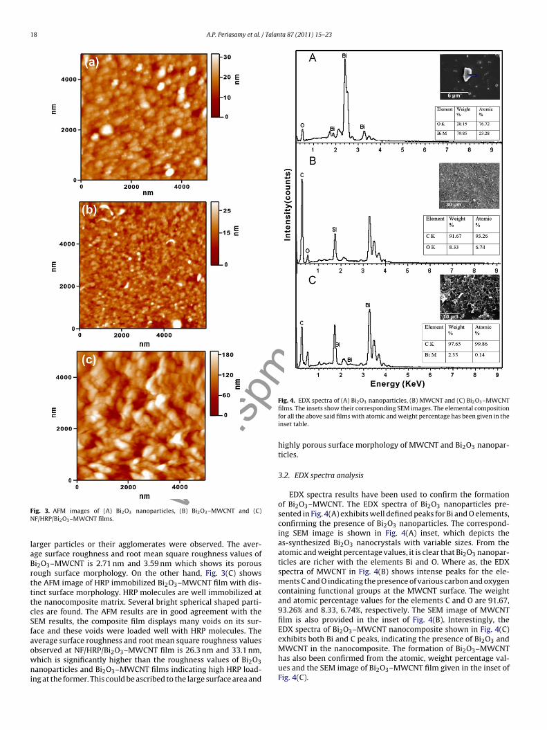
Fig. 4. EDX spectra of (A) Bi2O3 nanoparticles, (B) MWCNT and (C) Bi2O3–MWCNT
MWCNT in the nanocomposite. The formation of Bi O –MWCNT
wig. 3. AFM images of (A) Bi2O3 nanoparticles, (B) Bi2O3–MWCNT and (C)F/HRP/Bi2O3–MWCNT films.
arger particles or their agglomerates were observed. The aver-ge surface roughness and root mean square roughness values ofi2O3–MWCNT is 2.71 nm and 3.59 nm which shows its porousough surface morphology. On the other hand, Fig. 3(C) showshe AFM image of HRP immobilized Bi2O3–MWCNT film with dis-inct surface morphology. HRP molecules are well immobilized athe nanocomposite matrix. Several bright spherical shaped parti-les are found. The AFM results are in good agreement with theEM results, the composite film displays many voids on its sur-ace and these voids were loaded well with HRP molecules. Theverage surface roughness and root mean square roughness values
bserved at NF/HRP/Bi2O3–MWCNT film is 26.3 nm and 33.1 nm,hich is significantly higher than the roughness values of Bi2O3anoparticles and Bi2O3–MWCNT films indicating high HRP load-ng at the former. This could be ascribed to the large surface area and
films. The insets show their corresponding SEM images. The elemental compositionfor all the above said films with atomic and weight percentage has been given in theinset table.
highly porous surface morphology of MWCNT and Bi2O3 nanopar-ticles.
3.2. EDX spectra analysis
EDX spectra results have been used to confirm the formationof Bi2O3–MWCNT. The EDX spectra of Bi2O3 nanoparticles pre-sented in Fig. 4(A) exhibits well defined peaks for Bi and O elements,confirming the presence of Bi2O3 nanoparticles. The correspond-ing SEM image is shown in Fig. 4(A) inset, which depicts theas-synthesized Bi2O3 nanocrystals with variable sizes. From theatomic and weight percentage values, it is clear that Bi2O3 nanopar-ticles are richer with the elements Bi and O. Where as, the EDXspectra of MWCNT in Fig. 4(B) shows intense peaks for the ele-ments C and O indicating the presence of various carbon and oxygencontaining functional groups at the MWCNT surface. The weightand atomic percentage values for the elements C and O are 91.67,93.26% and 8.33, 6.74%, respectively. The SEM image of MWCNTfilm is also provided in the inset of Fig. 4(B). Interestingly, theEDX spectra of Bi2O3–MWCNT nanocomposite shown in Fig. 4(C)exhibits both Bi and C peaks, indicating the presence of Bi2O3 and
2 3has also been confirmed from the atomic, weight percentage val-ues and the SEM image of Bi2O3–MWCNT film given in the inset ofFig. 4(C).
m
A.P. Periasamy et al. / Talanta 87 (2011) 15– 23 19
FpB
3
ccpo2oF�PrBsc
3
Bsi(Hn
www.sp
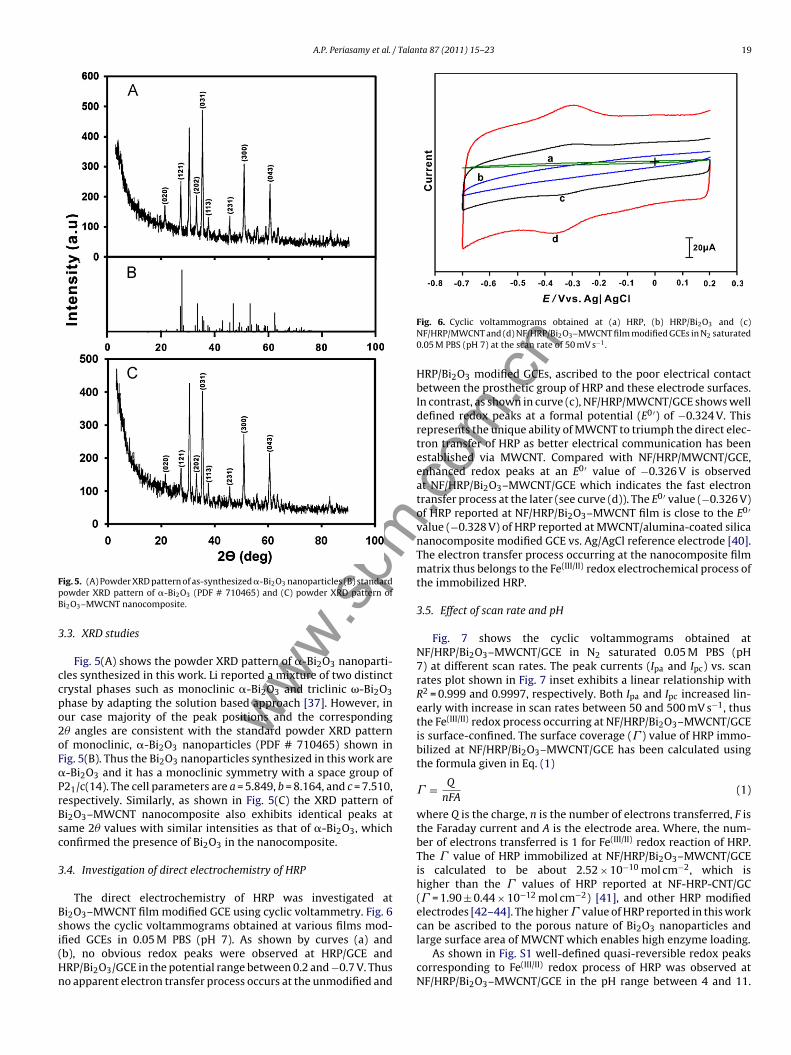
ig. 5. (A) Powder XRD pattern of as-synthesized �-Bi2O3 nanoparticles (B) standardowder XRD pattern of �-Bi2O3 (PDF # 710465) and (C) powder XRD pattern ofi2O3–MWCNT nanocomposite.
.3. XRD studies
Fig. 5(A) shows the powder XRD pattern of �-Bi2O3 nanoparti-les synthesized in this work. Li reported a mixture of two distinctrystal phases such as monoclinic �-Bi2O3 and triclinic �-Bi2O3hase by adapting the solution based approach [37]. However, inur case majority of the peak positions and the corresponding� angles are consistent with the standard powder XRD patternf monoclinic, �-Bi2O3 nanoparticles (PDF # 710465) shown inig. 5(B). Thus the Bi2O3 nanoparticles synthesized in this work are-Bi2O3 and it has a monoclinic symmetry with a space group of21/c(14). The cell parameters are a = 5.849, b = 8.164, and c = 7.510,espectively. Similarly, as shown in Fig. 5(C) the XRD pattern ofi2O3–MWCNT nanocomposite also exhibits identical peaks atame 2� values with similar intensities as that of �-Bi2O3, whichonfirmed the presence of Bi2O3 in the nanocomposite.
.4. Investigation of direct electrochemistry of HRP
The direct electrochemistry of HRP was investigated ati2O3–MWCNT film modified GCE using cyclic voltammetry. Fig. 6hows the cyclic voltammograms obtained at various films mod-
fied GCEs in 0.05 M PBS (pH 7). As shown by curves (a) andb), no obvious redox peaks were observed at HRP/GCE andRP/Bi2O3/GCE in the potential range between 0.2 and −0.7 V. Thuso apparent electron transfer process occurs at the unmodified and.com
.cn
Fig. 6. Cyclic voltammograms obtained at (a) HRP, (b) HRP/Bi2O3 and (c)NF/HRP/MWCNT and (d) NF/HRP/Bi2O3–MWCNT film modified GCEs in N2 saturated0.05 M PBS (pH 7) at the scan rate of 50 mV s−1.
HRP/Bi2O3 modified GCEs, ascribed to the poor electrical contactbetween the prosthetic group of HRP and these electrode surfaces.In contrast, as shown in curve (c), NF/HRP/MWCNT/GCE shows welldefined redox peaks at a formal potential (E0 ′) of −0.324 V. Thisrepresents the unique ability of MWCNT to triumph the direct elec-tron transfer of HRP as better electrical communication has beenestablished via MWCNT. Compared with NF/HRP/MWCNT/GCE,enhanced redox peaks at an E0 ′ value of −0.326 V is observedat NF/HRP/Bi2O3–MWCNT/GCE which indicates the fast electrontransfer process at the later (see curve (d)). The E0 ′ value (−0.326 V)of HRP reported at NF/HRP/Bi2O3–MWCNT film is close to the E0 ′
value (−0.328 V) of HRP reported at MWCNT/alumina-coated silicananocomposite modified GCE vs. Ag/AgCl reference electrode [40].The electron transfer process occurring at the nanocomposite filmmatrix thus belongs to the Fe(III/II) redox electrochemical process ofthe immobilized HRP.
3.5. Effect of scan rate and pH
Fig. 7 shows the cyclic voltammograms obtained atNF/HRP/Bi2O3–MWCNT/GCE in N2 saturated 0.05 M PBS (pH7) at different scan rates. The peak currents (Ipa and Ipc) vs. scanrates plot shown in Fig. 7 inset exhibits a linear relationship withR2 = 0.999 and 0.9997, respectively. Both Ipa and Ipc increased lin-early with increase in scan rates between 50 and 500 mV s−1, thusthe Fe(III/II) redox process occurring at NF/HRP/Bi2O3–MWCNT/GCEis surface-confined. The surface coverage (� ) value of HRP immo-bilized at NF/HRP/Bi2O3–MWCNT/GCE has been calculated usingthe formula given in Eq. (1)
� = Q
nFA(1)
where Q is the charge, n is the number of electrons transferred, F isthe Faraday current and A is the electrode area. Where, the num-ber of electrons transferred is 1 for Fe(III/II) redox reaction of HRP.The � value of HRP immobilized at NF/HRP/Bi2O3–MWCNT/GCEis calculated to be about 2.52 × 10⁻¹⁰ mol cm−2, which ishigher than the � values of HRP reported at NF-HRP-CNT/GC(� = 1.90 ± 0.44 × 10⁻¹² mol cm−2) [41], and other HRP modifiedelectrodes [42–44]. The higher � value of HRP reported in this workcan be ascribed to the porous nature of Bi2O3 nanoparticles and
large surface area of MWCNT which enables high enzyme loading.As shown in Fig. S1 well-defined quasi-reversible redox peakscorresponding to Fe(III/II) redox process of HRP was observed atNF/HRP/Bi2O3–MWCNT/GCE in the pH range between 4 and 11.

m
20 A.P. Periasamy et al. / Talanta 87 (2011) 15– 23
Fig. 7. Cyclic voltammograms obtained at NF/HRP/Bi2O3–MWCNT film modifiedGCE in N2 saturated 0.05 M PBS (pH 7) at different scan rates. The scan rates fromiTr
Tpwpoaroptfistot
3
ttbtwpnNhtbwc
3
smIfi
Fig. 8. (a) EIS of (a) bare, (b) HRP, (c) Bi2O3–MWCNT, (d) MWCNT, (e)NF/HRP/MWCNT, and (f) NF/HRP/Bi2O3–MWCNT film modified GCEs in 0.05 M
www.spnner to outer are between 50, 100, 150, 200, 250, 300, 350, 400, 450, and 500 mV s−1.he inset shows the linear dependence plot of peak currents (Ipa and Ipc) vs. scanates/V s−1.
his shows the stability of the composite film in wide pH range. Inarticular, well defined redox peaks with enhanced peak currentsere observed in pH 7 as the HRP retains its bioactivity in neutralH. Fig. S1 inset, shows the linear dependence of Epa, Epc and E0 ′
f the redox couple of HRP with pH. The E0 ′ values showed a neg-tive shift with increase in pH with a slope value of 41.8 mV pH−1,espectively. This slope value is close to the theoretical slope valuef 59 mV pH−1 for equal number of electron and proton transferrocess. The slope value of HRP reported in this study is also closero the slope of 37.8 mV pH−1 reported at HRP/DDAB–HIMIMPF6lm [42]. As explained in previous literature, the reasons for themaller slope values might be ascribed to the protonation states ofrans ligands to the heme iron and amino acids around the heme,r because of the protonation of the water molecule coordinated tohe central iron [45,46].
.6. Biocompatibility study using UV–vis absorption spectroscopy
UV–vis absorption spectra can be used as an effective toolo probe whether the heme proteins retain their native struc-ure at the immobilization matrix. This kind of information cane explicated from the exact location and from the shift in posi-ion of the soret absorption band of heme prosthetic group. Soe utilized UV–vis absorption spectroscopy as a handy tool torobe whether HRP retains its native structure at Bi2O3–MWCNTanocomposite. Fig. S2 shows the UV–visible absorption spectra ofF/HRP/Bi2O3–MWCNT film. A broad absorption band at 400 nmas been observed for NF/HRP/Bi2O3–MWCNT film which is closeo the soret band of HRP casted films (404 nm and 406 nm) reportedefore [47]. Since HRP retains its soret band without any notableavelength shift, the nanocomposite matrix should be highly bio-
ompatible for the immobilized HRP.
.7. EIS studies at various film modified GCEs
Fig. 8 shows the real and imaginary parts of the impedance
pectra represented as Nyquist plots (Zim vs. Zre) for various filmodified GCEs in 0.05 M PBS (pH 7) containing 5 mM Fe(CN)63−/4−.n Fig. 8, curve (a) displays well defined semicircle at unmodi-ed GCE which indicates the sluggish electron transfer process.
.com
.cn
PBS (pH 7) containing 5 mM Fe(CN)63−/Fe(CN)6
4− . Amplitude: 5 mV, frequency:100 mHz–100 kHz. EIS data obtained at all modified electrodes were fitted usingthe Randles equivalence circuit given in the inset.
Compared with bare GCE, HRP modified GCE shown in curve (b)exhibits slightly larger semicircle than bare GCE. The increase inthe electron transfer resistance (Ret) value at HRP/GCE is due tothe inaccessibility of the heme redox entre since it is covered bythick polypeptide layer. Unlike the unmodified and HRP modifiedGCEs, Bi2O3–MWCNT and MWCNT modified GCEs does not showany semicircles instead they exhibited straight lines representingthe diffusion-limited electrochemical process (see curves (c) and(d)). The decrease in Ret values at Bi2O3–MWCNT and MWCNT mod-ified GCE surfaces showed the excellent electron transfer ability ofMWCNT. Similarly as shown in curves (e) and (f), NF/HRP/MWCNTand NF/HRP/Bi2O3–MWCNT film modified GCEs showed slightlybent lines with increased Ret values which can be ascribed to thenon-conductive properties of HRP which hinder the electron trans-fer of the electrochemical probe [48]. Thus EIS results confirmed theimmobilization of HRP at the nanocomposite.
3.8. Electrocatalytic H2O2 reduction studies
We investigated the electrocatalytic activity of the HRPimmobilized nanocomposite film towards H2O2 in 0.05 M PBS(pH 7). Fig. 9(a) shows the cyclic voltamograms obtained atNF/HRP/Bi2O3–MWCNT/GCE in the absence of H2O2. While thecurves (b-i) represents the cyclic voltammograms obtained at thecomposite film in presence of various H2O2 concentrations. Anenhanced catalytic reduction peak was observed at an Ipc of −0.18 Vfor 3.6 �M H2O2 (curve b). Since then, the cathodic peak cur-rents increased gradually with increase in H2O2 concentrationswhile anodic peak currents decreased ((Fig. 9(c–i)). Where, boththe increase in peak current and decrease in over potential areconsidered as electrocatalysis [49]. In contrast, bare GCE exhibitsill-defined peak at −0.6 V for 222.2 �M H2O2, which shows its poorelectrocatalytic activity towards H2O2 (see curve (a′) in Fig. 9).Compared with the H2O2 reduction potential (−0.6 V) of bare GCE,composite film modified GCE exhibits enhanced reduction peak atmuch lower potential (−0.23 V), which indicates that compositefilm has reduced the over potential by 370 mV. The good electro-catalytic activity can be ascribed to the synergistic effect of thenanocomposite towards H2O2. The NF/HRP/Bi2O3–MWCNT/GCE
exhibits promising electrocatalytic activity towards H2O2 in the lin-ear concentration range between 19.2 and 222.1 �M H2O2 with asensitivity of 1.62 �A mM−1 cm−2. The linear regression equationis I (�A) = 0.1282C (�M) + 2.2514, R2 = 0.9845.
m
A.P. Periasamy et al. / Talan
Fig. 9. Cyclic voltammograms obtained at NF/HRP/Bi2O3–MWCNT/GCE at the scanrate of 50 mV s−1 in the (a) absence and presence of (b) 3.6 (c) 19.2, (d) 50.9, (e) 72.0,( ′
2p
awgmcscvricue
veies
FBi(
.spf) 82.2, (g) 121.0, (h) 176.0, and (i) 222.2 �M H2O2, (a ) bare/GCE in the presence of22.2 �M H2O2. Supporting electrolyte: N2 saturated 0.05 M PBS (pH 7). Inset is thelot of cathodic peak current vs. [H2O2].
We investigated the influence of NF coating on the electrocat-lytic activity of HRP using CV studies. The NF concentrations usedere 0.25, 0.5, 0.75, 1.0 and 1.25%, respectively. Cyclic voltammo-
rams were obtained at the biosensors fabricated using the aboveentioned NF concentrations in N2 saturated 0.05 M PBS (pH 7)
ontaining 100 �M H2O2 at the scan rate of 50 mV s−1 (CVs nothown). From the as-obtained cyclic voltammograms, the electro-atalytic reduction current has been calculated and plotted againstarious NF concentrations as shown in Fig. S3. It is clear that, theesponse current increased slightly for 0.25 and 0.5% NF, where ast decreased for 0.75 and 1.25% NF. However, maximum responseurrent was observed at the biosensor fabricated with 1% NF, so wesed this optimized NF concentration for all our electrocatalyticxperiments.
We also attempted to compare the electrocatalytic activity ofarious modified electrodes. In Fig. 10, curves (a–d) show thelectrocatalytic responses obtained at various modified electrodes
wwwn the presence of 222.1 �M H2O2. Among all the investigatedlectrodes, as shown in curve (d), NF/HRP/Bi2O3–MWCNT/GCEhows enhanced electrocatalytic reduction peak at much low
ig. 10. Cyclic voltammograms obtained at (a) MWCNT, (b) NF/HRP/MWCNT, (c)i2O3–MWCNT, and (d) NF/HRP/Bi2O3–MWCNT/GCEs at the scan rate of 50 mV s−1
n the presence of 222.1 �M H2O2. Supporting electrolyte is N2 saturated 0.05 M PBSpH 7).
.com
.cn
ta 87 (2011) 15– 23 21
reduction potential of −0.223 V. Comparatively, as shown incurves (a and b) MWCNT, and NF/HRP/MWCNT/GCE displayedsmall shoulder peaks at −0.412 V and −0.223 V, respectively.While as shown in curve (c), Bi2O3–MWCNT modified elec-trode exhibits an enhanced reduction peak at −0.339. It isnoteworthy that compared with MWCNT and Bi2O3–MWCNTfilms, the NF/HRP/Bi2O3–MWCNT/GCE considerably decreased theoverpotential by 189 and 176 mV respectively. Moreover, theelectrocatalytic current observed at the composite film is sev-eral folds higher than the electrocatalytic current observed atNF/HRP/MWCNT/GCE. The excellent electrocatalytic H2O2 reduc-tion results achieved at NF/HRP/Bi2O3–MWCNT film corroboratesits low potential H2O2 sensing ability, which could be ascribed tothe good biocompatibility of the Bi2O3–MWCNT nanocomposite forHRP and synergistic effect of the Bi2O3–MWCNTs for H2O2.
3.9. Amperometric i–t curve studies
During the amperometric experiments the electrode potentialwas held at −0.3 V and the N2 saturated 0.05 M PBS (pH 7) wascontinuously stirred at 900 rpm. For every 50 s, aliquots of H2O2were successively injected into the supporting electrolyte solu-tion. Fig. 11(A) shows the amperometric i–t response obtained atNF/HRP/Bi2O3–MWCNT rotating GCE upon various H2O2 concen-tration additions. The composite film exhibits rapid, well-definedamperometric response towards various H2O2 concentrationadditions. The response time of the NF/HRP/Bi2O3–MWCNT com-posite film towards H2O2 was 5 s, validating the rapid catalyticreduction process occurring at the composite film surface. Theamperometric response current increased linearly with increasein H2O2 concentrations between 6.63 mM and 30.12 mM H2O2(Fig. 11(A) inset). From the calibration plot, the linear concentrationrange, correlation coefficient and the sensitivity values are calcu-lated as 8.34–28.88 mM H2O2, 0.9743 and 26.54 �A mM−1 cm−2,respectively. The linear regression equation is I (�A) = 6.3698C(�M) + 7.0994, R2 = 0.9743. The essential analytical parameterssuch as applied potential, sensitivity, response time and linearconcentration range of the proposed NF/HRP/Bi2O3–MWCNT filmhave been compared with other HRP based biosensors available inliterature [50–52,26,53–55,36] as exemplified in Table 1. The pro-posed biosensor detects H2O2 at low operating potential (−0.3 V vs.Ag/AgCl), with high sensitivity, short response time in wide linearconcentration range. The satisfactory amperometric H2O2 deter-mination results achieved at the NF/HRP/Bi2O3–MWCNT film inthis study could be attributed to the good affinity of the immo-bilized HRP for H2O2 and the efficient immobilization of HRP atBi2O3–MWCNT matrix.
It is well known that the biological fluids contain H2O2 alongwith ascorbic acid (AA), uric acid (UA), and dopamine (DA).Therefore, the selectivity of the developed NF/HRP/Bi2O3–MWCNTcomposite film is mandatory and it was evaluated in the pres-ence of the above said interfering species in same 0.05 M PBS (pH7). In Fig. 11(B), NF/HRP/Bi2O3–MWCNT film shows rapid, welldefined amperometric response towards 100 �M H2O2. In contrast,no notable amperometric signals were observed for each 100 �M ofUA, AA and DA concentration additions. The selectivity results thusconfirmed that the proposed HRP biosensor is highly selective andit successfully overcomes the matrix effect caused by the commoninterferences. The good selectivity of the composite film could beascribed to the anti-interference ability of the outer NF layer [56].
The operational stability of NF/HRP/Bi2O3–MWCNT modi-fied rotating disc electrode was examined by amperometry.
Fig. S4 shows the amperometric i–t response observed atNF/HRP/Bi2O3–MWCNT film for 100 �M H2O2. Under hydronamicrotating conditions (900 rpm), the composite film exhibits welldefined amperometric response for 100 �M H2O2 and the response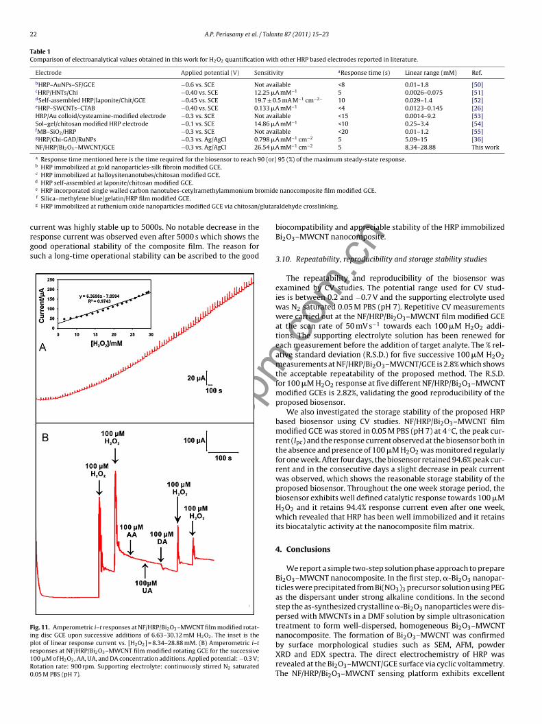
22 A.P. Periasamy et al. / Talanta 87 (2011) 15– 23
Table 1Comparison of electroanalytical values obtained in this work for H2O2 quantification with other HRP based electrodes reported in literature.
Electrode Applied potential (V) Sensitivity aResponse time (s) Linear range (mM) Ref.
bHRP–AuNPs–SF/GCE −0.6 vs. SCE Not available <8 0.01–1.8 [50]cHRP/HNTs/Chi −0.40 vs. SCE 12.25 �A mM−1 5 0.0026–0.075 [51]dSelf-assembled HRP/laponite/Chit/GCE −0.45 vs. SCE 19.7 ± 0.5 mA M−1 cm−2− 10 0.029–1.4 [52]eHRP–SWCNTs–CTAB −0.40 vs. SCE 0.133 �A mM−1 <4 0.0123–0.145 [26]HRP/Au colloid/cysteamine-modified electrode −0.3 vs. SCE Not available <15 0.0014–9.2 [53]Sol–gel/chitosan modified HRP electrode −0.1 vs. SCE 14.86 �A mM−1 <10 0.25–3.4 [54]fMB–SiO2/HRP −0.3 vs. SCE Not available <20 0.01–1.2 [55]gHRP/Chi-GAD/RuNPs −0.3 vs. Ag/AgCl 0.798 �A mM−1 cm−2 5 5.09–15 [36]NF/HRP/Bi2O3–MWCNT/GCE −0.3 vs. Ag/AgCl 26.54 �A mM−1 cm−2 5 8.34–28.88 This work
a Response time mentioned here is the time required for the biosensor to reach 90 (or) 95 (%) of the maximum steady-state response.b HRP immobilized at gold nanoparticles-silk fibroin modified GCE.c HRP immobilized at halloysitenanotubes/chitosan modified GCE.d HRP self-assembled at laponite/chitosan modified GCE.
omide
glutar
crgs
Fipr1R0
e HRP incorporated single walled carbon nanotubes-cetylramethylammonium brf Silica–methylene blue/gelatin/HRP film modified GCE.g HRP immobilized at ruthenium oxide nanoparticles modified GCE via chitosan/
www.spm
urrent was highly stable up to 5000s. No notable decrease in theesponse current was observed even after 5000 s which shows theood operational stability of the composite film. The reason foruch a long-time operational stability can be ascribed to the good
ig. 11. Amperometric i–t responses at NF/HRP/Bi2O3–MWCNT film modified rotat-ng disc GCE upon successive additions of 6.63–30.12 mM H2O2. The inset is thelot of linear response current vs. [H2O2] = 8.34–28.88 mM. (B) Amperometric i–tesponses at NF/HRP/Bi2O3–MWCNT film modified rotating GCE for the successive00 �M of H2O2, AA, UA, and DA concentration additions. Applied potential: −0.3 V;otation rate: 900 rpm. Supporting electrolyte: continuously stirred N2 saturated.05 M PBS (pH 7).
.com
.cn
nanocomposite film modified GCE.
aldehyde crosslinking.
biocompatibility and appreciable stability of the HRP immobilizedBi2O3–MWCNT nanocomposite.
3.10. Repeatability, reproducibility and storage stability studies
The repeatability and reproducibility of the biosensor wasexamined by CV studies. The potential range used for CV stud-ies is between 0.2 and −0.7 V and the supporting electrolyte usedwas N2 saturated 0.05 M PBS (pH 7). Repetitive CV measurementswere carried out at the NF/HRP/Bi2O3–MWCNT film modified GCEat the scan rate of 50 mV s−1 towards each 100 �M H2O2 addi-tions. The supporting electrolyte solution has been renewed foreach measurement before the addition of target analyte. The % rel-ative standard deviation (R.S.D.) for five successive 100 �M H2O2measurements at NF/HRP/Bi2O3–MWCNT/GCE is 2.8% which showsthe acceptable repeatability of the proposed method. The R.S.D.for 100 �M H2O2 response at five different NF/HRP/Bi2O3–MWCNTmodified GCEs is 2.82%, validating the good reproducibility of theproposed biosensor.
We also investigated the storage stability of the proposed HRPbased biosensor using CV studies. NF/HRP/Bi2O3–MWCNT filmmodified GCE was stored in 0.05 M PBS (pH 7) at 4 ◦C, the peak cur-rent (Ipc) and the response current observed at the biosensor both inthe absence and presence of 100 �M H2O2 was monitored regularlyfor one week. After four days, the biosensor retained 94.6% peak cur-rent and in the consecutive days a slight decrease in peak currentwas observed, which shows the reasonable storage stability of theproposed biosensor. Throughout the one week storage period, thebiosensor exhibits well defined catalytic response towards 100 �MH2O2 and it retains 94.4% response current even after one week,which revealed that HRP has been well immobilized and it retainsits biocatalytic activity at the nanocomposite film matrix.
4. Conclusions
We report a simple two-step solution phase approach to prepareBi2O3–MWCNT nanocomposite. In the first step, �-Bi2O3 nanopar-ticles were precipitated from Bi(NO3)3 precursor solution using PEGas the dispersant under strong alkaline conditions. In the secondstep the as-synthesized crystalline �-Bi2O3 nanoparticles were dis-persed with MWCNTs in a DMF solution by simple ultrasonicationtreatment to form well-dispersed, homogeneous Bi2O3–MWCNTnanocomposite. The formation of Bi2O3–MWCNT was confirmed
by surface morphological studies such as SEM, AFM, powderXRD and EDX spectra. The direct electrochemistry of HRP wasrevealed at the Bi2O3–MWCNT/GCE surface via cyclic voltammetry.The NF/HRP/Bi2O3–MWCNT sensing platform exhibits excellent
m
/ Talan
esHcigeih
A
t
A
t
R
[
[
[
[
[[
[
[
[
[[
[[[[
[[[[
[[[[[
[
[[
[[[[[[[[
[
[
[[[[[[
[53] X. Yi, J.H. Xian, C.H. Yuan, Anal. Biochem. 278 (2000) 22–28.
pA.P. Periasamy et al.
lectrocatalytic response towards H2O2 in wide range with highensitivity and it considerably decreased the over potential for2O2 reduction. The nanocomposite sensing platform offers effi-ient enzyme loading and it facilitates fast electron transfer andt provides remarkable operational stability and selectivity withood biocompatibility. The preset work may thus encourage thexploitation of MWCNT–metal oxide nanocomposites as potentmmobilization matrices for probing the direct electrochemistry ofeme group containing redox enzymes.
cknowledgement
This work was supported by the National Science Council andhe Ministry of Education of Taiwan (Republic of China).
ppendix A. Supplementary data
Supplementary data associated with this article can be found, inhe online version, at doi:10.1016/j.talanta.2011.09.021.
eferences
[1] L. Agui, P.Y. Sedeno, J.M. Pingarron, Anal. Chim. Acta 622 (2008) 11–47.[2] P.A. Prakash, U. Yogeswaran, S.M. Chen, Talanta 78 (2009) 1414–1421.[3] A. Mikolajczuk, A. Borodzinski, L. Stobinski, P. Kedzierzawski, B. Lesiak, L. Kover,
J. Toth, H.M. Lin, Phys. Status Solidi B 247 (2010) 3063–3067.[4] T. Sawatsuk, A. Chindaduang, C.S. Kung, S. Pratontep, G. Tumcharern, Diam.
Relat. Mater. 18 (2009) 524–527.[5] S. Campidelli, C. Klumpp, A. Bianco, D.M. Guldi, M. Prato, J. Phys. Org. Chem. 19
(2006) 531–539.[6] U. Yogeswaran, S. Thiagarajan, S.M. Chen, Anal. Biochem. 365 (2007) 122–131.[7] W.D. Zhang, B. Xu, L.C. Jiang, J. Mater. Chem. 20 (2010) 6383–6391.[8] U. Yogeswaran, S.M. Chen, Sens. Actuators B 130 (2008) 739–749.[9] Y. Umasankar, A.P. Periasamy, S.M. Chen, Anal. Biochem. 411 (2011) 71–79.10] M.Md. Rahman, A.J.S. Ahammad, J.H. Jin, S.J. Ahn, J.J. Lee, Sensors 10 (2010)
4855–4886.11] A. Arvinte, A.C. Westermann, A.M. Sesay, V. Virtanen, Sens. Actuators B 150
(2010) 756–763.12] Z. Fan, J. Chen, M. Wang, K. Cui, H. Zhou, Y. Kuang, Diam. Relat. Mater. 15 (2006)
1478–1483.13] Y. Zhang, X. Sun, L. Pan, H. Li, Z. Sun, C. Sun, B.K. Tay, Solid State Ionics 180
(2009) 1525–1528.
www.s14] A. Goyal, A.L.M. Reddy, P.M. Ajayan, Small 7 (2011) 1709–1713.15] X. Chen, S. Chen, W. Huang, J. Zheng, Z. Li, Electrochim. Acta 54 (2009)
7370–7373.16] M. Khairy, R.O. Kadara, D.K. Kampouris, C.E. Banks, Electroanalysis 22 (2010)
1455–1459.
[[
[
.com
.cn
ta 87 (2011) 15– 23 23
17] M. Zidan, T.W. Tee, A.H. Abdullah, Z. Zainal, G.J. Kheng, Int. J. Electrochem. Sci.6 (2011) 279–288.
18] S. Taufik, N.A. Yusof, T.W. Tee, I. Ramli, Int. J. Electrochem. Sci. 6 (2011)1880–1891.
19] S.N. Ding, D. Shan, H.G. Xue, S. Cosnier, Bioelectrochemistry 79 (2010) 218–222.20] D. Shan, J. Zhang, H.G. Xue, Y.C. Zhang, S. Cosnier, S.N. Ding, Biosens. Bioelectron.
24 (2009) 3671–3676.21] R.J. Weston, Food Chem. 71 (2000) 235–239.22] M.I. Prodromidis, M.I. Karayannis, Electroanalysis 14 (2002) 241–261.23] N.C. Veitch, Phytochemistry 65 (2004) 249–259.24] S.V. Dzyadevych, V.N. Arkhypova, A.P. Soldatkin, A.V. Elskaya, C. Martelet, N.
Jaffrezic-Renault, ITBM–RBM 29 (2008) 171.25] Y. Yang, G. Yang, Y. Huang, H. Bai, X. Lu, Colloids Surf. A 340 (2009) 50–55.26] S. Wang, F. Xie, G. Liu, Talanta 77 (2009) 1343–1350.27] C. Xiang, Y. Zou, L.X. Sun, F. Xu, Sens. Actuators B 136 (2009) 158–162.28] Y. Wang, X. Ma, Y. Wen, Y. Xing, Z. Zhang, H. Yang, Biosens. Bioelectron. 25
(2010) 2442–2446.29] Y. Astuti, E. Topoglidis, A.G. Cass, J.R. Durrant, Anal. Chim. Acta 648 (2009) 2–6.30] J. Liu, Y. Li, X. Huang, Z. Zhu, Nanoscale Res. Lett. 5 (2010) 1177–1181.31] P. He, N. Hu, Electroanalysis 16 (2004) 1122.32] A.A. Ansari, P.R. Solanki, B.D. Malhotra, J. Biotechnol. 142 (2009) 179–184.33] A. Mohammadi, A.B. Moghaddam, M. Kazemzad, R. Dinarvand, J. Badraghi,
Mater. Sci. Eng. C 29 (2009) 1752–1758.34] X. Yang, X. Chen, X. Zhang, W. Yang, D.G. Evans, Sens. Actuators B 134 (2008)
182–188.35] S. Zong, Y. Cao, Y. Zhou, H. Ju, Langmuir 22 (2006) 8915–8919.36] A.P. Periasamy, S.W. Ting, S.M. Chen, Int. J. Electrochem. Sci. 6 (2011)
2688–2709.37] W. Li, Mater. Chem. Phys. 99 (2006) 174–180.38] Y. Zhou, N. Hu, Y. Zeng, J.F. Rusling, Langmuir 18 (2002) 211–219.39] Q. Huang, Z. Lu, J.F. Rusling, Langmuir 12 (1996) 5472–5480.40] J.L. Huang, Y.C. Tsai, Sens. Actuators B 140 (2009) 267–272.41] Y. Yin, Y. Lu, P. Wu, C. Cai, Sensors 5 (2005) 220–234.42] Y. Xu, C. Hu, S. Hu, Anal. Chim. Acta 663 (2010) 19–26.43] J.Z. Xu, J.J. Zhu, Q. Wu, Z. Hu, H.Y. Chen, Electroanalysis 15 (2003) 219–224.44] J.S. Long, D.S. Silvester, G.G. Wildgoose, A.E. Surkus, G. Flechsig, R.G. Compton,
Bioelectrochemistry 74 (2008) 183–187.45] Y.X. Sun, J.T. Zhang, S.W. Huang, S.F. Wang, Sens. Actuators B 124 (2007)
494–500.46] I. Yamazaki, T. Araiso, Y. Hayashi, H. Yamada, R. Makino, Adv. Biophys. 11 (1978)
249–281.47] X. Chen, X. Peng, J. Kong, J. Deng, J. Electroanal. Chem. 480 (2000) 26–33.48] N. Tang, J. Zheng, Q. Sheng, H. Zhang, R. Liu, Analyst 136 (2011) 781–786.49] C.P. Andrieux, O. Haas, J.M. Savgant, J. Am. Chem. Soc. 108 (1986) 8175–8182.50] H. Yin, S. Ai, W. Shi, L. Zhu, Sens. Actuators B 137 (2009) 747–753.51] X. Sun, Y. Zhang, H. Shen, N. Jia, Electrochim. Acta 56 (2010) 700–705.52] D. Shan, Q.B. Li, S.N. Ding, J.Q. Xu, S. Cosnier, H.G. Xue, Biosens. Bioelectron. 26
(2010) 536–541.
54] Y. Miao, S.N. Tan, Anal. Chim. Acta 437 (2001) 87–93.55] H. Yao, N. Li, S. Xu, J.Z. Xu, J.J. Zhu, H.Y. Chen, Biosens. Bioelectron. 21 (2005)
372–377.56] F.O. Brown, J.P. Lowry, Analyst 128 (2003) 700–705.