predicting models for the evaluation of out-of-plane ... · pdf filepredicting models for the...
TRANSCRIPT

Predicting models for the evaluation of out-of-plane ultimate load carrying capacity of masonry infill walls
M. Pasca & L. Liberatore Department of Structural Engineering and Geotechnics, Sapienza University of Rome, Italy
Abstract
In recent years, the interest in the out-of-plane response of infills has been growing due to the need of limiting damage to these elements, commonly considered as non structural. Different experimental tests and theoretical studies have been carried out on this subject. They highlighted that the slenderness and the boundary conditions of the panel, the mechanical characteristics of the masonry, the stiffness of the surrounding frame elements and the presence of cracks due to prior in-plane damage noticeably affect the out-of-plane carrying capacity of infill walls. In this paper, a review and a comparison of analytical models developed for the assessment of the out-of-plane response of masonry infills is presented. The suitability of selected models to predict the out-of-plane capacity is investigated by means of some experimental results available in the literature. It is concluded that, even though the considered models take into account the main parameters involved (slenderness of the panel, masonry compressive strength, etc.), they are not always able to adequately predict the actual resistance. Keywords: masonry infills, predicting models, out-of-plane carrying capacity, slenderness, boundary conditions.
1 Introduction
The observation of damage after earthquakes has highlighted that out-of-plane failures of masonry infill walls may often occur even in case of low or moderate earthquakes [1]. Out-of-plane failure of infills may occur even for moderate intensity of the ground motion. In many cases, the structure
Earthquake Resistant Engineering Structures X 83
www.witpress.com, ISSN 1743-3509 (on-line) WIT Transactions on The Built Environment, Vol 152, © 2015 WIT Press
doi:10.2495/ERES150071

withstands the ground shaking with minor damage, whereas infills collapse in-plane or out-of-plane. During the 2009 L’Aquila (Italy) earthquake, masonry infill panels failed out-of-plane due to the lack of connections between the two wythes of the masonry panels [2]. As a matter of fact, one of the most common damage in L’Aquila and the surrounding towns to reinforced concrete frames was damage to exterior infill walls and interior partitions, varying from small cracks to collapse [3]. Some buildings displayed complete loss of the masonry infill walls at lower stories. There were also occurrences of out-of-plane failure of a single layer of the infill, like also observed during the 2012 Emilia (Italy) earthquake [4]. Tilting of infills have been also observed during the 1999 Athens earthquake [5], the 2004 Molise earthquake [6] and the 2011 Lorca earthquake [7]. The failure of infills, which may develop both in-plane and/or out-of-plane, causes casualty risk and heavy socio-economic consequences, such as loss of building functionality. Moreover, the total or partial collapse of an infill may cause unfavourable situations affecting the overall structural response, e.g. the formation of an open storey, which may lead to a soft-storey mechanism. Most studies on infill panels have been focused on their in-plane response. However, in recent years the interest in the out-of-plane behaviour has been growing. Experimental tests have been conducted by different researchers to asses strength and ductility of masonry walls loaded in the out-of-plane direction. The published literature reports monotonic, cyclic and dynamic tests on masonry panels. Such studies have investigated the influence of various factors, e.g. the slenderness ratio, the panel thickness, the boundary conditions, the presence of prior in-plane damage. A review is presented in [8]. Experimental tests have shown the importance of the boundary conditions. If the infill is confined along all the edges, curves of out-of-plane load versus deflection of the infill show four stages. In the first stage the behaviour is linear elastic; in the second stage the propagation of cracks and the development of a yield-line failure mechanism occurs; in the third stage, arching of infill causes the load to increase and finally, in the fourth stage the load drops off due to crushing of masonry at the crack lines and at the interface with the confining frame until total collapse. Different boundary conditions or high flexibility of the frame elements may not allow the arching mechanism to develop thus reducing the out-of-plane capacity of the wall. Both the slenderness (i.e. the height/thickness ratio) of the panel and the presence of prior in-plane damage affect the out-of-plane stiffness and strength of the wall. However such dependence is in turn influenced by the boundary conditions. The presence of reinforcing elements in the masonry, e.g. reinforcement in the mortar layers or wire meshes in the external plaster, was found to be strongly beneficial. The effect of openings on the out-of-plane resistance has not been investigated sufficiently up to now and deserves further investigation. As a matter of fact, the few studies available in the literature present dissimilar results. However, it is possible to state that openings may accelerate the out-of-plane
84 Earthquake Resistant Engineering Structures X
www.witpress.com, ISSN 1743-3509 (on-line) WIT Transactions on The Built Environment, Vol 152, © 2015 WIT Press

failure because they affect the in-plane stiffness and strength [9], thus increasing the in-plane damage. In this paper, a review and a comparison of analytical models developed for the assessment of the out-of-plane carrying capacity of masonry infills is presented, focusing on models based on the arching theory. Approaches involving finite element methods or iterative procedures (e.g. [10, 11]) are not investigated in this study.
2 Code provisions
2 ′
⁄ (1)
in which q is the uniform pressure on the wall which causes out-of-plane failure, is the masonry compressive strength, is the slenderness parameter, and
are the height and thickness of the infill, respectively, is a reduction factors depending on previous in-plane damage and is a reduction factor accounting for the frame flexibility. According to FEMA 356 [15], unreinforced infill panels with slenderness ratios less than specified values and meeting the requirements for arching action (i.e. panel in full contact with the surrounding frame elements, frame components with sufficient stiffness and strength to resist thrusts from arching actions, etc.) need not to be analysed for out-of-plane seismic forces. Limit values of the slenderness vary from 8 to 16 depending on the performance level and on the seismic zone. If the slenderness limits are not accomplished but requirements for arching action are met, then the following expression is provided for the evaluation of the lower bound out-of-plane strength q of an infill panel:
0.7 ′
⁄ (2)
where: is the lower bound of masonry compressive strength, is the slenderness parameter, and are the height and thickness of the infill, respectively. This expression is a modification of eqn (1), the numerical constant 2 in eqn (1) is changed to 0.7 in eqn (2) and the parameter 2 in eqn (2) is lower than eqn (1). These modifications are due to the fact that the FEMA 356 expression provides a lower-bound prediction of out-of-plane strength. When arching action is not considered, the lower bound strength of the infill panel should be evaluated as a function of the lower bound masonry flexural tension strength. According to Eurocode 8 [16] out-of-plane collapse of slender masonry panels should be avoided by means of specific measures. Particular attention is
Earthquake Resistant Engineering Structures X 85
www.witpress.com, ISSN 1743-3509 (on-line) WIT Transactions on The Built Environment, Vol 152, © 2015 WIT Press
Recommendations for infill walls subjected to out-of-plane loads are provided in different codes and commentary. In FEMA 306 [12] and NZSEE recommendations [13] the equation proposed by Angel et al. [14] for the assessment of the out-of-plane infill strength is reported:

required for masonry panels with slenderness ratio greater than 15. Examples of measures, which are suggested for the improvement of both in-plane and out-of- plane behaviour, include: light wire meshes, wall ties fixed to the columns, wind-posts and concrete belts. In the Italian specifications [17] the use of light wire meshes with wires spaced no more than 500 mm out anchored on both sides of the masonry panel and connected to the frame elements or the adoption of reinforcing steel bars in the bed joints are suggested. If such measures are taken, then the verification under seismic actions perpendicular to the infill may be neglected, otherwise the effects of the seismic force acting in the out-of-plane direction should be assessed. No capacity models are suggested in both EC8 and current Italian code.
3 Predicting models
Different analytical models have been developed for the prediction of the out-of-plane ultimate load carrying capacity of masonry infill walls. A simple model to represent two-way bending of an infill is that of an elastic plate through classical solutions by Timoshenko (1959). With this model, failure is assumed to occur when the tensile stress reaches the tensile strength of the masonry. Approaches based on the modified yield-line analyses have been also developed. The yield-line analysis consists in defining a kinematically admissible mechanism (yield-line mechanism) and calculating the limit load by equating the internal and external works. Based on the yield-line analysis Haseltine et al. [18] and Hendry [19] proposed equations in which the out-of-plane strength is expressed as a function of the flexural tensile strength normal to the bed joints. Other models are based on rigid body mechanisms, either with or without the description of the arching behaviour (Figure 1). In the rigid-body mechanism with a hinge at the bottom of the panel (Figure 1(a)), out-of-plane stability is verified by the equilibrium condition between the stabilizing action (weight of the wall) and the overturning action (seismic action). This scheme is consistent with panels having a weak vertical restraint at the top. Static and dynamic models for this condition have been proposed by Sorrentino et al. [20]. The static model may also account for the formation of an intermediate hinge. A second scheme is defined by assuming an arching behaviour (Figure 1(b)), in this case the collapse is related to a three hinges mechanism, which is usually activated along the shorter dimension. This model is consistent with panels restrained by the surrounding frame. One of the first models formulated to predict the lateral strength of one-way spanning brickwork beams with rigid supports due to arching was proposed by McDowell et al. [21] in 1956. In [21] the wall is modelled as an ideal beam constrained between rigid supports on the two edges. According to the model, cracks develop on the tension side at the centre and edges of the beam and, after this phase the two portions of the beam are supposed to behave as rigid bodies, rotating around one
86 Earthquake Resistant Engineering Structures X
www.witpress.com, ISSN 1743-3509 (on-line) WIT Transactions on The Built Environment, Vol 152, © 2015 WIT Press
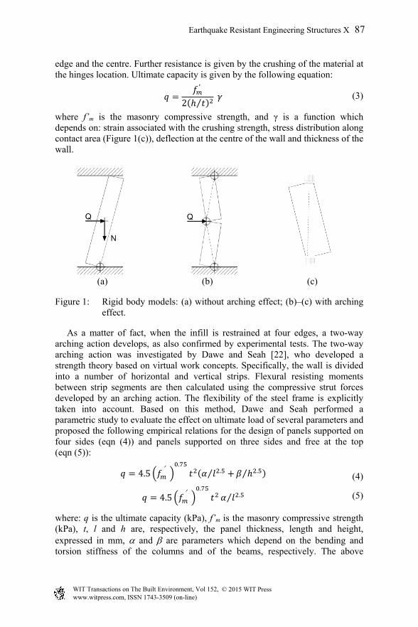
edge and the centre. Further resistance is given by the crushing of the material at the hinges location. Ultimate capacity is given by the following equation:
′
2 ⁄ (3)
where f’m is the masonry compressive strength, and γ is a function which depends on: strain associated with the crushing strength, stress distribution along contact area (Figure 1(c)), deflection at the centre of the wall and thickness of the wall.
(a) (b) (c)
Figure 1: Rigid body models: (a) without arching effect; (b)–(c) with arching effect.
As a matter of fact, when the infill is restrained at four edges, a two-way arching action develops, as also confirmed by experimental tests. The two-way arching action was investigated by Dawe and Seah [22], who developed a strength theory based on virtual work concepts. Specifically, the wall is divided into a number of horizontal and vertical strips. Flexural resisting moments between strip segments are then calculated using the compressive strut forces developed by an arching action. The flexibility of the steel frame is explicitly taken into account. Based on this method, Dawe and Seah performed a parametric study to evaluate the effect on ultimate load of several parameters and proposed the following empirical relations for the design of panels supported on four sides (eqn (4)) and panels supported on three sides and free at the top (eqn (5)):
4.5 ′.
.⁄ .⁄ (4)
4.5 ′.
.⁄ (5)
where: q is the ultimate capacity (kPa), f’m is the masonry compressive strength (kPa), t, l and h are, respectively, the panel thickness, length and height, expressed in mm, and are parameters which depend on the bending and torsion stiffness of the columns and of the beams, respectively. The above
Earthquake Resistant Engineering Structures X 87
www.witpress.com, ISSN 1743-3509 (on-line) WIT Transactions on The Built Environment, Vol 152, © 2015 WIT Press

equations have been derived for hollow concrete block panels within steel frame having pinned joints. Eqn (4) was modified by Flanagan and Bennett [23] on the basis of 36 experimental tests reported in the literature on steel and concrete frames infilled with clay and concrete masonry. The numerical constant 4.5 was modified into 4.1 and the expression for parameters and was simplified by eliminating the terms of torsion stiffness of the frame members. The effect of in-plane damage on the out-of-plane resistance was first investigated by Angel et al. [14] and Abrams et al. [24], who developed a model to evaluate the out-of-plane strength of cracked panels based on the one-way arching theory. The panel is assumed to crack at midspan and to develop internal thrust to resist a uniformly applied pressure. The out-of-plane strength is then calculated by the equilibrium between the acting internal pressure at the contact area and the internal thrust. The expression suggested for the out-of-plane strength (eqn (1)) derives from both equilibrium considerations and experimental results. The reduction factor, R1, is considered to account for the magnitude of prior in-plane damage [24]:
1.08 0.015 ⁄ 0.00049 ⁄ 0.000013 ⁄Δ
Δ (6)
where is the in-plane maximum horizontal displacement and crack is the in-plane displacement at which the first crack is expected to occur. R2 accounts for the flexibility of confining frame. If an infill panels is confined within a frame having neighbouring panels in every direction, then R2 =1. Otherwise the reduction factor R2 is given by the following expressions:
0.357 7.14 10 EI for 2 10 EI 9 10
1 for EI 9 10 (7)
where EI is the flexural rigidity (expressed in kip-in2) of the smallest frame member at the side where a neighbouring panel is missing [14]. Eqn (1) is valid when the out-of-plane strength is governed by arching of the panel, such a mechanism takes place when the slenderness of the panel is smaller than the following critical value [24]:
0.9812
(8)
When the slenderness of the panel is greater than the critical one, the snap through occurs before the attainment of the ultimate compressive strain cu. For example for an ultimate compressive strain of 0.005, the critical slenderness is about 19 (Figure 2). In order to include two-way arching action, Bashandy et al. [25] extended the analytical method developed by McDowell et al. [21] considering a model based on the crack pattern in Figure 3. Orthogonal stripes with a yield pattern in both directions are introduced; as the yield pattern is given like in Figure 3, all horizontal stripes and some vertical stripes will not experience the maximum
88 Earthquake Resistant Engineering Structures X
www.witpress.com, ISSN 1743-3509 (on-line) WIT Transactions on The Built Environment, Vol 152, © 2015 WIT Press

moment, and the maximum out-of-plane deflection will be governed by the crushing of masonry in the central vertical stripes.
Figure 2: Maximum strain at contact area, max, versus panel slenderness h/t [23].
Figure 3: Crack pattern in infill wall and strips model [25].
The total force resistance, Q, is calculated assuming an equivalent rectangular stress pattern in the contact area of hinges location and it is obtained by the sum of the forces resisted by all the horizontal and vertical stripes according to the following expression:
8 8 2 82⁄
(9)
where xyh and xyv are the deflections about horizontal and vertical axes, respectively and are given by the following equations:
′
1 2 2⁄ (10)
0.000
0.005
0.010
0.015
0.020
5 10 15 20 25 30 35 40
max
h/t
(h/t)cr
cu
Earthquake Resistant Engineering Structures X 89
www.witpress.com, ISSN 1743-3509 (on-line) WIT Transactions on The Built Environment, Vol 152, © 2015 WIT Press
′
1 2 2⁄ (11)
f’m is the ultimate compressive strength; Em is the masonry modulus of elasticity, t is the panel thickness; h and l are the panel height and width, respectively; Myv and Myh are obtained by substituting the values of xyh and xyv respectively in eqn (12) in lieu of xy.
0.85 ′
4 (12)
When using eqn (9), attention should be paid in the case in which the calculated horizontal deflection is greater than the panel thickness, in this case the contribution of the horizontal strips should be neglected.
4 Comparisons between different models
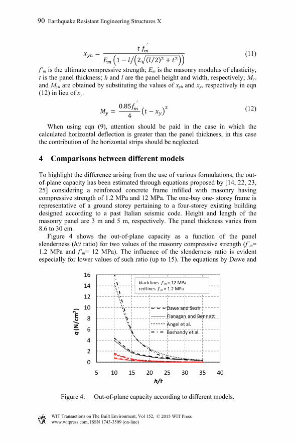
To highlight the difference arising from the use of various formulations, the out-of-plane capacity has been estimated through equations proposed by [14, 22, 23, 25] considering a reinforced concrete frame infilled with masonry having compressive strength of 1.2 MPa and 12 MPa. The one-bay one- storey frame is representative of a ground storey pertaining to a four-storey existing building designed according to a past Italian seismic code. Height and length of the masonry panel are 3 m and 5 m, respectively. The panel thickness varies from 8.6 to 30 cm. Figure 4 shows the out-of-plane capacity as a function of the panel slenderness (h/t ratio) for two values of the masonry compressive strength (f’m= 1.2 MPa and f’m= 12 MPa). The influence of the slenderness ratio is evident especially for lower values of such ratio (up to 15). The equations by Dawe and
Figure 4: Out-of-plane capacity according to different models.
0
2
4
6
8
10
12
14
16
5 10 15 20 25 30 35 40
q(N/cm
2 )
h/t
Dawe and Seah Flanagan and BennettAngel et al.Bashandy et al.
black lines f'm= 12 MPared lines f'm= 1.2 MPa
90 Earthquake Resistant Engineering Structures X
www.witpress.com, ISSN 1743-3509 (on-line) WIT Transactions on The Built Environment, Vol 152, © 2015 WIT Press
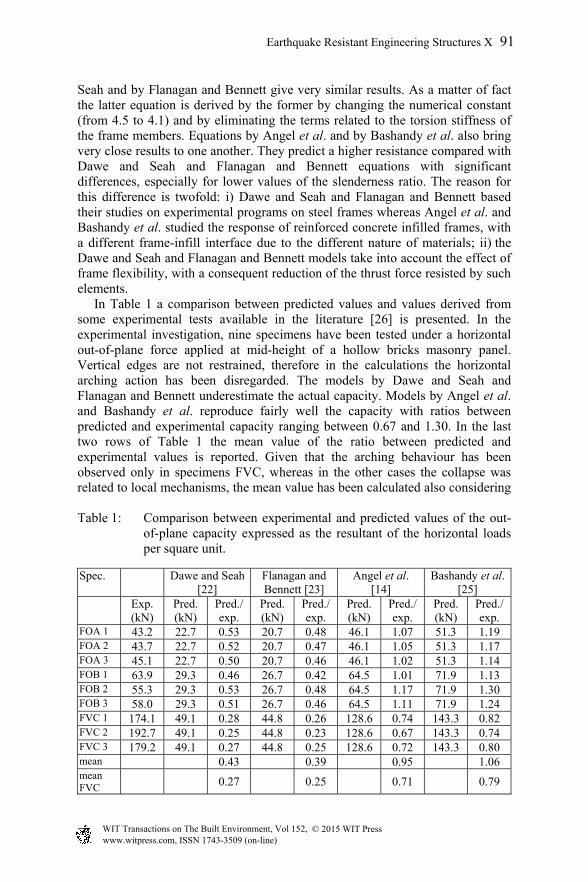
Seah and by Flanagan and Bennett give very similar results. As a matter of fact the latter equation is derived by the former by changing the numerical constant (from 4.5 to 4.1) and by eliminating the terms related to the torsion stiffness of the frame members. Equations by Angel et al. and by Bashandy et al. also bring very close results to one another. They predict a higher resistance compared with Dawe and Seah and Flanagan and Bennett equations with significant differences, especially for lower values of the slenderness ratio. The reason for this difference is twofold: i) Dawe and Seah and Flanagan and Bennett based their studies on experimental programs on steel frames whereas Angel et al. and Bashandy et al. studied the response of reinforced concrete infilled frames, with a different frame-infill interface due to the different nature of materials; ii) the Dawe and Seah and Flanagan and Bennett models take into account the effect of frame flexibility, with a consequent reduction of the thrust force resisted by such elements. In Table 1 a comparison between predicted values and values derived from some experimental tests available in the literature [26] is presented. In the experimental investigation, nine specimens have been tested under a horizontal out-of-plane force applied at mid-height of a hollow bricks masonry panel. Vertical edges are not restrained, therefore in the calculations the horizontal arching action has been disregarded. The models by Dawe and Seah and Flanagan and Bennett underestimate the actual capacity. Models by Angel et al. and Bashandy et al. reproduce fairly well the capacity with ratios between predicted and experimental capacity ranging between 0.67 and 1.30. In the last two rows of Table 1 the mean value of the ratio between predicted and experimental values is reported. Given that the arching behaviour has been observed only in specimens FVC, whereas in the other cases the collapse was related to local mechanisms, the mean value has been calculated also considering
Table 1: Comparison between experimental and predicted values of the out-of-plane capacity expressed as the resultant of the horizontal loads per square unit.
Spec. Dawe and Seah [22]
Flanagan and Bennett [23]
Angel et al. [14]
Bashandy et al. [25]
Exp. (kN)
Pred. (kN)
Pred./ exp.
Pred. (kN)
Pred./ exp.
Pred. (kN)
Pred./ exp.
Pred. (kN)
Pred./ exp.
FOA 1 43.2 22.7 0.53 20.7 0.48 46.1 1.07 51.3 1.19 FOA 2 43.7 22.7 0.52 20.7 0.47 46.1 1.05 51.3 1.17 FOA 3 45.1 22.7 0.50 20.7 0.46 46.1 1.02 51.3 1.14 FOB 1 63.9 29.3 0.46 26.7 0.42 64.5 1.01 71.9 1.13 FOB 2 55.3 29.3 0.53 26.7 0.48 64.5 1.17 71.9 1.30 FOB 3 58.0 29.3 0.51 26.7 0.46 64.5 1.11 71.9 1.24 FVC 1 174.1 49.1 0.28 44.8 0.26 128.6 0.74 143.3 0.82 FVC 2 192.7 49.1 0.25 44.8 0.23 128.6 0.67 143.3 0.74 FVC 3 179.2 49.1 0.27 44.8 0.25 128.6 0.72 143.3 0.80 mean 0.43 0.39 0.95 1.06 mean FVC 0.27 0.25 0.71 0.79
Earthquake Resistant Engineering Structures X 91
www.witpress.com, ISSN 1743-3509 (on-line) WIT Transactions on The Built Environment, Vol 152, © 2015 WIT Press

only the last three specimens. Considering the FVC results, the models by Angel et al. and Bashandy et al. are slightly conservative but approximate the experimental values better than the other models. Finally, it is useful to note that the predicted values have been calculated using the characteristic strength, which was available in [26]. The use of a mean strength would lead to more conservative results.
5 Conclusions
Experimental tests and numerical analyses performed on infill masonry walls have pointed out the importance of the arching effects in evaluating the ultimate carrying capacity of walls subjected to out-of-plane actions. Ultimate load carrying capacity and final configuration depend on geometry and material properties of the walls, bending and torsion stiffness of the frame members and prior in-plane damage. Different analytical predictive expressions are available to estimate the out-of-plane capacity of infill walls. Usually, these expressions are calibrated or verified through comparison with experimental results and are thus related to a specific type of frame (reinforced concrete or steel) and of masonry (brick masonry, concrete block, etc.) and their use in different situations should be examined carefully. Models based on the arching behaviour provide conservative or unconservative estimates of the capacity according to the model under consideration. Moreover, there are situations in which the arching behaviour does not develop even in the case of small slenderness [26, 27]. A comparison with experimental results performed in this study has shown that, for the considered infills, the expressions by Dawe and Seah [22] and Flanagan and Bennett [23] underestimate the actual capacity, whereas those by Angel et al. [14] and Bashandy et al. [25] provide a better estimation of the capacity. Further study is needed to assess the range of validity of various formulations.
Acknowledgements
The financial support of the Ministry of the Instruction, University and Research of Italy (MIUR) is gratefully acknowledged. This work has been partially carried out under the program “Dipartimento di Protezione Civile – Consorzio RELUIS”, signed on 2013-12-27, Research Line WP5.
References
[1] Manfredi, V. & Masi, A., Combining in-plane and out-of-plane behaviour of masonry infills in the seismic analysis of RC buildings. Earthquake and Structures, 6(5), pp. 515–537, 2014.
[2] Braga, F., Manfredi, V., Masi, A., Salvatori, A. & Vona, M., Performance of non-structural elements in RC buildings during the L’Aquila, 2009 earthquake. Bulletin of Earthquake Engineering, 9, pp. 307–324, 2011.
92 Earthquake Resistant Engineering Structures X
www.witpress.com, ISSN 1743-3509 (on-line) WIT Transactions on The Built Environment, Vol 152, © 2015 WIT Press

[3] Decanini, L.D., Liberatore, L. & Mollaioli, F., Damage potential of the 2009 L’Aquila, Italy, earthquake. Journal of Earthquake and Tsunami, 6(3), pp. 1250032:1–32, 2012.
[4] Liberatore, L., Sorrentino, L., Liberatore, D. & Decanini, L.D., Performance of reinforced concrete residential buildings during the Emilia (Italy) 2012 Earthquakes. SE-50EEE International Conference on Earthquake Engineering, Skopje, Macedonia, 2013.
[5] Decanini, L.D., De Sortis, A., Liberatore, L. & Mollaioli, F., Estimation of near-source ground motion and seismic behaviour of RC framed structures damaged by the 1999 Athens earthquake. Journal of Earthquake Engineering, 9(5), pp. 609–635, 2005.
[6] Decanini, L.D., De Sortis, A., Goretti, A., Liberatore, L., Mollaioli, F. & Bazzurro, P., Performance of reinforced concrete buildings during the 2002 Molise, Italy, Earthquake. Earthquake Spectra, 20:S1, pp. S221–S255, 2004.
[7] Hermanns, L., Fraile, A., Alarcón, E. & Álvarez R., Performance of buildings with masonry infill walls during the 2011 Lorca earthquake. Bulletin of Earthquake Engineering, 12, pp. 1977–1997, 2014.
[8] Liberatore, L. & Pasca, M., Out-of-plane response of infill masonry walls. 9th International Masonry Conference, Guimarães, Portugal, 2014.
[9] Decanini, L.D., Liberatore, L. and Mollaioli, F., Strength and stiffness reduction factors for infilled frames with openings. Earthquake Engineering and Engineering Vibration, 13(3), pp. 437–454, 2014.
[10] Tasnimi, A.A. & Zomorodi, E., The Effect of Onplane Behavior on Inplane Interaction of URM Infilled RC Frame Under Lateral Loads. 14th European Conference on Earthquake Engineering, Ohrid, Macedonia, 2010.
[11] Varela-Rivera, J., Moreno-Herrera, J., Lopez-Gutierrez, I. & Fernandez-Baqueiro, L., Out-of-Plane Strength of Confined Masonry Walls. Journal of Structural Engineering, 138, pp. 1331–1341, 2012.
[12] FEMA 306, Evaluation of earthquake damaged concrete and masonry wall buildings. Basic Procedures Manual, prepared by ATC Applied Technology Council, 1998.
[13] NZSEE Recommendations, Assessment and Improvement of the Structural Performance of Buildings in Earthquakes. New Zealand Society for Earthquake Engineering, Study Group on Earthquake Risk Buildings, 2006.
[14] Angel, R., Abrams, D., Shapiro, D., Uzarski, J. & Webster, M., Behaviour of Reinforced Concrete Frames with Masonry Infills, Report No. UILU-ENG-94-2005, Department of Civil Engineering, University of Illinois, Urbana-Champaign, IL, USA 1994.
[15] FEMA 356, Prestandard and commentary for the seismic rehabilitation of buildings. Prepared by ASCE (American Society of Civil Engineers), 2000.
Earthquake Resistant Engineering Structures X 93
www.witpress.com, ISSN 1743-3509 (on-line) WIT Transactions on The Built Environment, Vol 152, © 2015 WIT Press
[16] CEN (European Committee for Standardization), Eurocode 8: Design of structures for earthquake resistance, Part 1: General rules, seismic actions and rules for buildings DRAFT No. 6, 2003.
[17] Ministero delle Infrastrutture e dei Trasporti, Istruzioni per l’applicazione delle “Nuove norme tecniche per le costruzioni” di cui al decreto ministeriale 14 gennaio 2008, Circolare 2 febbraio 2009, n. 617.
[18] Haseltine, B.A., West, H.W.H. & Tutt, J.N., Design of Walls to Resist Lateral Loads. The Structural Engineers, 55(10), pp. 422 430, 1977.
[19] Hendry, A.W., The Lateral Strength of Unreinforced Brickwork. The Structural Engineers, 51(2), pp. 43–50, 1973.
[20] Sorrentino, L., Masiani, R. & Griffith, M.C., The vertical spanning strip wall as a coupled rocking rigid body assembly. Structural Engineers and Mechanics, 29(4), pp. 433–453, 2008.
[21] McDowell, E.L., McKee, K.E. & Sevin, E., Arching theory of masonry walls. Journal of the Structural Division, 82, pp. 915-1–915-18, 1956.
[22] Dawe, J.L. & Seah, C.K., Out-of-plane resistance of concrete masonry infilled panels. Canadian Journal of Civil Engineering, 16, pp. 854–864, 1989.
[23] Flanagan, R.D. & Bennett, R.M., Arching of masonry infilled frames: comparison of analytical methods, Practical Periodical on Structural Design and Construction, 4, pp. 105–110, 1999.
[24] Abrams, D.P., Angel, R. & Uzarski, J., Out of Plane Strength of Unreinforced Masonry Infill Panels. Earthquake Spectra, 12(4), pp. 825–844, 1996.
[25] Bashandy, T., Rubiano, N.R. & Klingner, R.E., Evaluation and Analytical Verification of Infilled Frame Test Data. U.S. Army Construction Engineering Research Laboratories CECER-CT-BAA, Seismic Structural Engineering (FM-4), Engineering and Material Division, Champaign, IL, 1995.
[26] Modena, C. & da Porto, F., Ricerca sperimentale sul comportamento fuori piano di tamponamenti in muratura in zona sismica. Research Report, Draft 1, Department of Construction and Transportation, University of Padua, Italy 2005 (in Italian).
[27] Komaraneni, S., Rai, D.C. & Singhal, V., Seismic Behavior of Framed Masonry Panels with Prior Damage When Subjected to Out-of-Plane Loading. Earthquake Spectra, 27, pp. 1077–1103, 2011.
94 Earthquake Resistant Engineering Structures X
www.witpress.com, ISSN 1743-3509 (on-line) WIT Transactions on The Built Environment, Vol 152, © 2015 WIT Press
–