precision barometer and altimeter sensor · adventure and sports watches ... 001: osr = 2048 100:...
TRANSCRIPT
DataSheet HP206C
PRECISION BAROMETER AND ALTIMETER SENSOR
Features
HP206C_DataSheet_EN_V2.0 www.hoperf.com 1 / 17
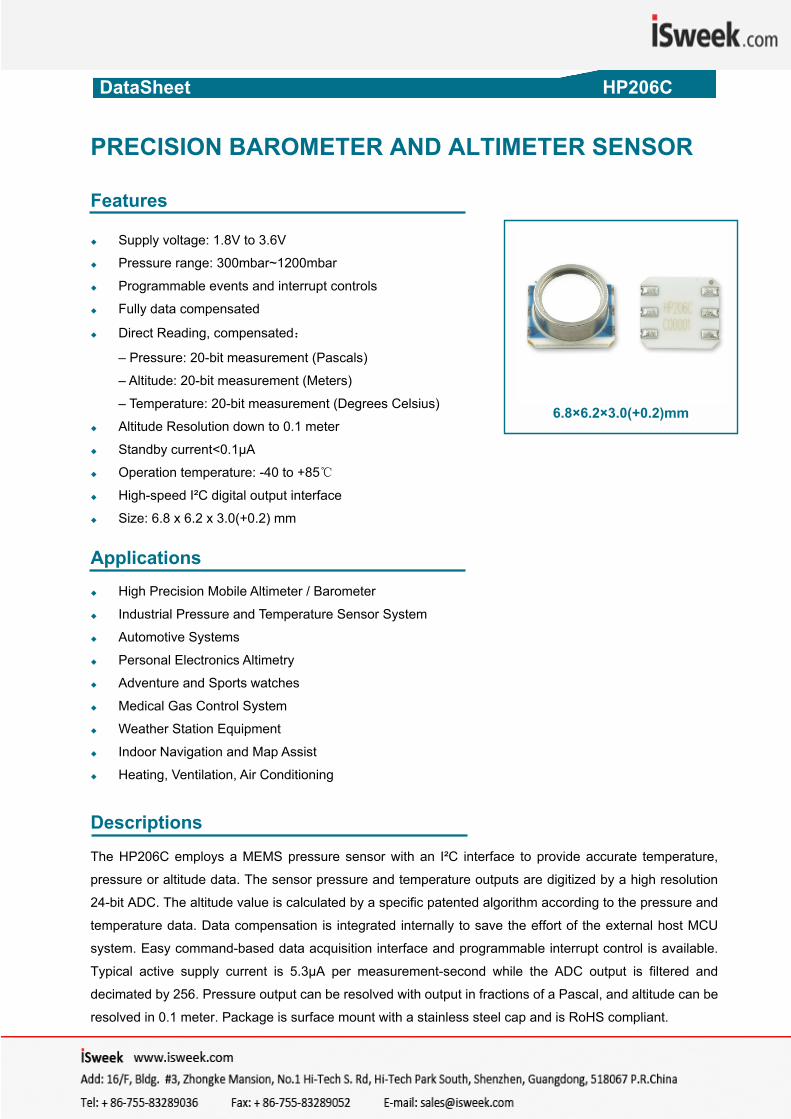
6.8×6.2×3.0(+0.2)mm
Supply voltage: 1.8V to 3.6V
Pressure range: 300mbar~1200mbar
Programmable events and interrupt controls
Fully data compensated
Direct Reading, compensated:
– Pressure: 20-bit measurement (Pascals)
– Altitude: 20-bit measurement (Meters)
– Temperature: 20-bit measurement (Degrees Celsius)
Altitude Resolution down to 0.1 meter
Standby current<0.1μA
Operation temperature: -40 to +85
High-speed I²C digital output interface
Size: 6.8 x 6.2 x 3.0(+0.2) mm Applications
High Precision Mobile Altimeter / Barometer
Industrial Pressure and Temperature Sensor System
Automotive Systems
Personal Electronics Altimetry
Adventure and Sports watches
Medical Gas Control System
Weather Station Equipment
Indoor Navigation and Map Assist
Heating, Ventilation, Air Conditioning
Descriptions
The HP206C employs a MEMS pressure sensor with an I²C interface to provide accurate temperature,
pressure or altitude data. The sensor pressure and temperature outputs are digitized by a high resolution
24-bit ADC. The altitude value is calculated by a specific patented algorithm according to the pressure and
temperature data. Data compensation is integrated internally to save the effort of the external host MCU
system. Easy command-based data acquisition interface and programmable interrupt control is available.
Typical active supply current is 5.3μA per measurement-second while the ADC output is filtered and
decimated by 256. Pressure output can be resolved with output in fractions of a Pascal, and altitude can be
resolved in 0.1 meter. Package is surface mount with a stainless steel cap and is RoHS compliant.

DataSheet HP206C
1. Block Diagram
Sensor
PGA 24-bit ADC
DigitalFilter
FullCompensation
AltitudeComputation
Temperature Sensor
Filtered data
Altitude data
Compensated data
12CInterface +InterruptControls
PORResetn
128-Byte NVM
Trim values
OSC LDO
VDD
SCL
SDA
INT1
GND
Figure 1: Functional block diagram
2. Mechanical and Electrical Specifications 2.1 Pressure and Temperature Characteristics Table1: Pressure Output Characteristics @ VDD = 3.0V, T = 25°C unless otherwise noted
Parameter Symbol Conditions Min Typ. Max Unit
Pressure MeasurementRange PFS 300 1200 mbar
Pressure Absolute Accuracy
700 to 1100 mbar from 0 to 50 -1.5 +1.5 mbar
700 to 1100 mbar from -20 to 70 -3 +3 mbar
Pressure Relative Accuracy
700 to 1100 mbar at 25 ±0.5 mbar
700 to 1100 mbar From 0 to 50 ±1.5 Max Error with Power Supply Power supply from 1.8V to 3.6V -2.5 +2.5 mbar
Pressure/Altitude Resolution
Pressure Mode 0.01 mbar
Altimeter Mode 0.10 m
Board Mount Drift After solder reflow ±0.5 mbar
Long Term Drift After a period of 1 year ±1.5 mbar
Reflow soldering impact IPC/JEDEC J-STD-020C +0.5 mbar
HP206C_DataSheet_EN_V2.0 www.hoperf.com 2 / 17
DataSheet HP206C
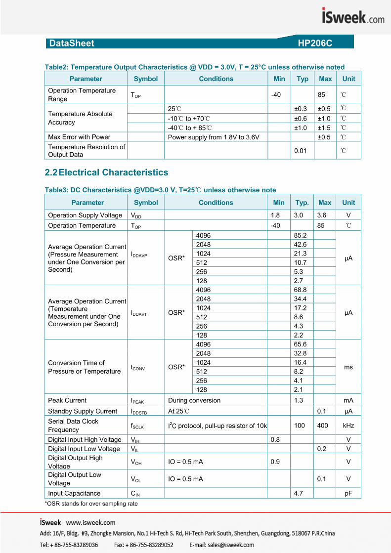
Table2: Temperature Output Characteristics @ VDD = 3.0V, T = 25°C unless otherwise noted Parameter Symbol Conditions Min Typ Max Unit
Operation Temperature Range TOP -40 85
Temperature Absolute Accuracy
25 ±0.3 ±0.5 -10 to +70 ±0.6 ±1.0 -40 to + 85 ±1.0 ±1.5
Max Error with Power Power supply from 1.8V to 3.6V ±0.5 Temperature Resolution of Output Data
0.01
2.2 Electrical Characteristics Table3: DC Characteristics @VDD=3.0 V, T=25 unless otherwise note
Parameter Symbol Conditions Min Typ. Max Unit
Operation Supply Voltage VDD 1.8 3.0 3.6 V Operation Temperature TOP -40 85
Average Operation Current (Pressure Measurement under One Conversion per Second)
IDDAVP OSR*
4096 85.2
μA
2048 42.6 1024 21.3 512 10.7 256 5.3 128 2.7
Average Operation Current (Temperature Measurement under One Conversion per Second)
IDDAVT OSR*
4096 68.8
μA
2048 34.4 1024 17.2 512 8.6 256 4.3 128 2.2
Conversion Time of Pressure or Temperature tCONV OSR*
4096 65.6
ms
2048 32.8 1024 16.4 512 8.2 256 4.1 128 2.1
Peak Current IPEAK During conversion 1.3 mA Standby Supply Current IDDSTB At 25 0.1 μA Serial Data Clock Frequency fSCLK I2C protocol, pull-up resistor of 10k 100 400 kHz
Digital Input High Voltage VIH 0.8 V Digital Input Low Voltage VIL 0.2 V Digital Output High Voltage
VOH IO = 0.5 mA 0.9 V
Digital Output Low Voltage VOL IO = 0.5 mA 0.1 V
Input Capacitance CIN 4.7 pF
*OSR stands for over sampling rate
HP206C_DataSheet_EN_V2.0 www.hoperf.com 3 / 17
DataSheet HP206C
HP206C_DataSheet_EN_V2.0 www.hoperf.com 4 / 17
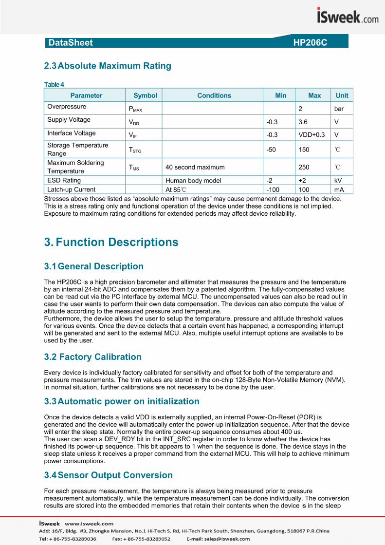
2.3 Absolute Maximum Rating Table 4
Parameter Symbol Conditions Min Max UnitOverpressure PMAX 2 bar
Supply Voltage VDD -0.3 3.6 V
Interface Voltage VIF -0.3 VDD+0.3 V Storage Temperature Range TSTG
-50 150
Maximum Soldering Temperature TMS 40 second maximum 250
ESD Rating Human body model -2 +2 kV Latch-up Current At 85 -100 100 mA
Stresses above those listed as “absolute maximum ratings” may cause permanent damage to the device. This is a stress rating only and functional operation of the device under these conditions is not implied. Exposure to maximum rating conditions for extended periods may affect device reliability. 3. Function Descriptions 3.1 General Description
The HP206C is a high precision barometer and altimeter that measures the pressure and the temperature by an internal 24-bit ADC and compensates them by a patented algorithm. The fully-compensated values can be read out via the I²C interface by external MCU. The uncompensated values can also be read out in case the user wants to perform their own data compensation. The devices can also compute the value of altitude according to the measured pressure and temperature. Furthermore, the device allows the user to setup the temperature, pressure and altitude threshold values for various events. Once the device detects that a certain event has happened, a corresponding interrupt will be generated and sent to the external MCU. Also, multiple useful interrupt options are available to be used by the user. 3.2 Factory Calibration Every device is individually factory calibrated for sensitivity and offset for both of the temperature and pressure measurements. The trim values are stored in the on-chip 128-Byte Non-Volatile Memory (NVM). In normal situation, further calibrations are not necessary to be done by the user. 3.3 Automatic power on initialization
Once the device detects a valid VDD is externally supplied, an internal Power-On-Reset (POR) is generated and the device will automatically enter the power-up initialization sequence. After that the device will enter the sleep state. Normally the entire power-up sequence consumes about 400 us. The user can scan a DEV_RDY bit in the INT_SRC register in order to know whether the device has finished its power-up sequence. This bit appears to 1 when the sequence is done. The device stays in the sleep state unless it receives a proper command from the external MCU. This will help to achieve minimum power consumptions. 3.4 Sensor Output Conversion
For each pressure measurement, the temperature is always being measured prior to pressure measurement automatically, while the temperature measurement can be done individually. The conversion results are stored into the embedded memories that retain their contents when the device is in the sleep
DataSheet HP206C
state. The conversion time depends on the value of the OSR parameter sent to the device within the ADC_CVT command. Six options of the OSR can be chosen, range from 128, 256 … to 4096. The below table shows the conversion time according to the different values of OSR: Table 5: Conversion Time VS OSR
OSR Conversion Time (ms)
Temperature Temperature and Pressure (or Altitude)
128 2.1 4.1256 4.1 8.2512 8.2 16.41024 16.4 32.82048 32.8 65.64096 65.6 131.1
The higher OSR will normally achieve higher measuring precision, but consume more time and power. The conversion results can be compensated or uncompensated. The user can enable/disable the compensation by setting the PARA register before performing the conversions. 3.5 Altitude Computation
The device can compute the altitude according to the measured pressure and temperature. The altitude value is updated and available to read as soon as the temperature and pressure measurement is done.
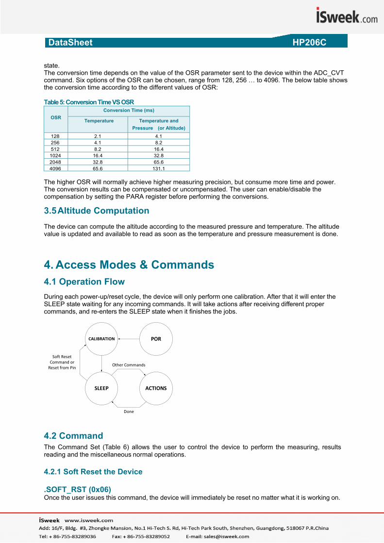
4. Access Modes & Commands 4 .1 Operation Flow During each power-up/reset cycle, the device will only perform one calibration. After that it will enter the SLEEP state waiting for any incoming commands. It will take actions after receiving different proper commands, and re-enters the SLEEP state when it finishes the jobs.
PORCALIBRATION
SLEEP ACTIONS
Other Commands
Done
Soft Reset Command or Reset from Pin
4.2 Command The Command Set (Table 6) allows the user to control the device to perform the measuring, results reading and the miscellaneous normal operations. 4.2.1 Soft Reset the Device .SOFT_RST (0x06) Once the user issues this command, the device will immediately be reset no matter what it is working on.
HP206C_DataSheet_EN_V2.0 www.hoperf.com 5 / 17
DataSheet HP206C
HP206C_DataSheet_EN_V2.0 www.hoperf.com 6 / 17
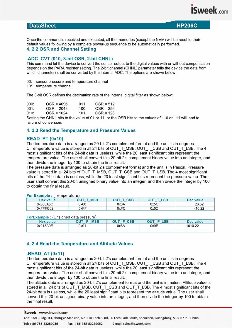
Once the command is received and executed, all the memories (except the NVM) will be reset to their default values following by a complete power-up sequence to be automatically performed. 4. 2.2 OSR and Channel Setting .ADC_CVT (010, 3-bit OSR, 2-bit CHNL) This command let the device to convert the sensor output to the digital values with or without compensation depends on the PARA register setting. The 2-bit channel (CHNL) parameter tells the device the data from which channel(s) shall be converted by the internal ADC. The options are shown below: 00: sensor pressure and temperature channel 10: temperature channel The 3-bit OSR defines the decimation rate of the internal digital filter as shown below: 000: OSR = 4096 011: OSR = 512 001: OSR = 2048 100: OSR = 256 010: OSR = 1024 101: OSR = 128 Setting the CHNL bits to the value of 01 or 11, or the OSR bits to the values of 110 or 111 will lead to failure of conversion. 4
. 2.3 Read the Temperature and Pressure Values
READ_PT (0x10) The temperature data is arranged as 20-bit 2’s complement format and the unit is in degrees C.Temperature value is stored in all 24 bits of OUT_T_MSB, OUT_T_CSB and OUT_T_LSB. The 4 most significant bits of the 24-bit data is useless, while the 20 least significant bits represent the temperature value. The user shall convert this 20-bit 2’s complement binary value into an integer, and then divide the integer by 100 to obtain the final result. The pressure data is arranged as 20-bit 2’s complement format and the unit is in Pascal. Pressure value is stored in all 24 bits of OUT_T_MSB, OUT_T_CSB and OUT_T_LSB. The 4 most significant bits of the 24-bit data is useless, while the 20 least significant bits represent the pressure value. The user shall convert this 20-bit unsigned binary value into an integer, and then divide the integer by 100 to obtain the final result.
For Example : (Temperature)
Hex value OUT_T_MSB OUT_T_CSB OUT_T_LSB Dec value0x000A5C 0x00 0x0A 0x5C 26.52 0xFFFC02 0xFF 0xFC 0x02 -10.22
ForExample : (Unsigned data pressure)
Hex value OUT_ P _MSB OUT_ P_CSB OUT_ P_LSB Dec value0x018A9E 0x01 0x8A 0x9E 1010.22
4. 2.4 Read the Temperature and Altitude Values .READ_AT (0x11) The temperature data is arranged as 20-bit 2’s complement format and the unit is in degrees C.Temperature value is stored in all 24 bits of OUT_T_MSB, OUT_T_CSB and OUT_T_LSB. The 4 most significant bits of the 24-bit data is useless, while the 20 least significant bits represent the temperature value. The user shall convert this 20-bit 2’s complement binary value into an integer, and then divide the integer by 100 to obtain the final result. The altitude data is arranged as 20-bit 2’s complement format and the unit is in meters. Altitude value is stored in all 24 bits of OUT_T_MSB, OUT_T_CSB and OUT_T_LSB. The 4 most significant bits of the 24-bit data is useless, while the 20 least significant bits represent the altitude value. The user shall convert this 20-bit unsigned binary value into an integer, and then divide the integer by 100 to obtain the final result.
DataSheet HP206C
HP206C_DataSheet_EN_V2.0 www.hoperf.com 7 / 17
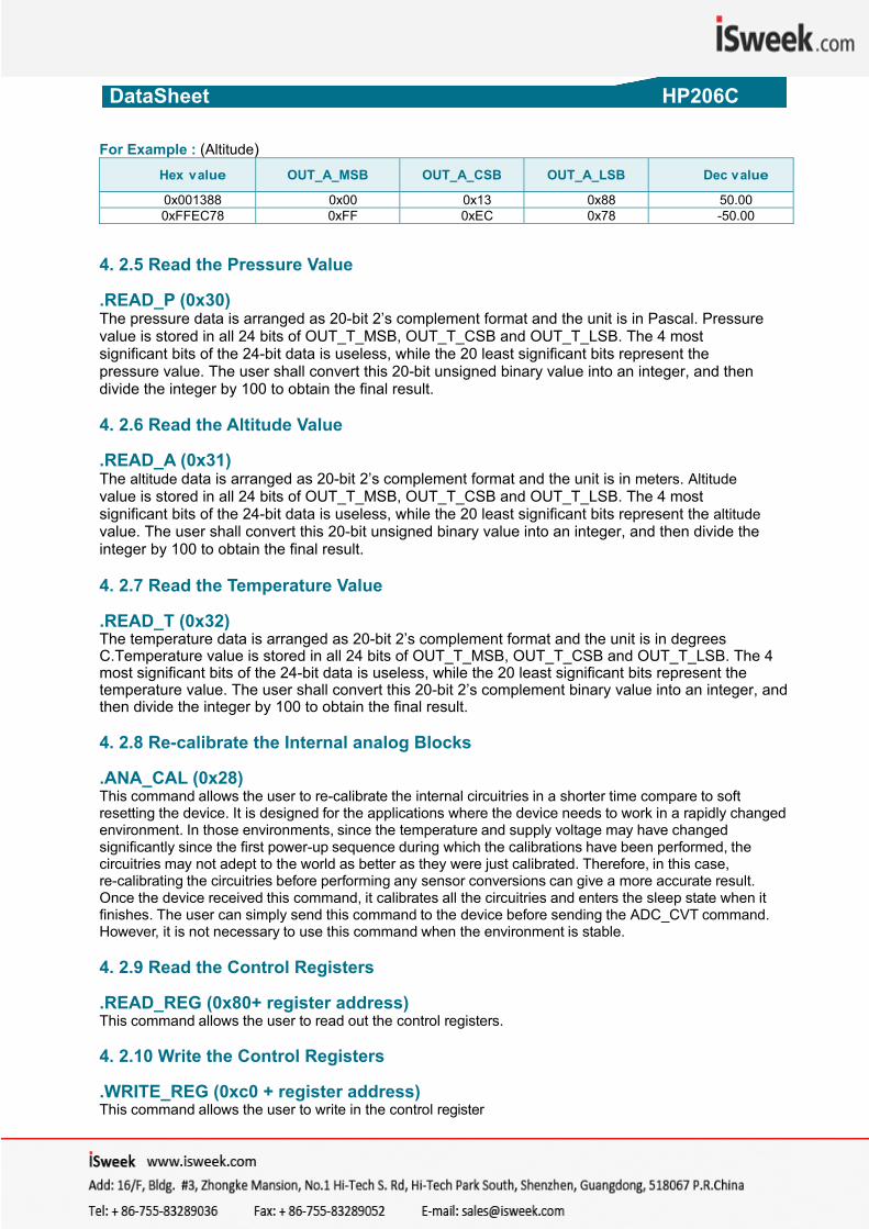
For Example : (Altitude) Hex value OUT_A_MSB OUT_A_CSB OUT_A_LSB Dec value
0x001388 0x00 0x13 0x88 50.00 0xFFEC78 0xFF 0xEC 0x78 -50.00
4. 2.5 Read the Pressure Value .READ_P (0x30) The pressure data is arranged as 20-bit 2’s complement format and the unit is in Pascal. Pressure value is stored in all 24 bits of OUT_T_MSB, OUT_T_CSB and OUT_T_LSB. The 4 most significant bits of the 24-bit data is useless, while the 20 least significant bits represent the pressure value. The user shall convert this 20-bit unsigned binary value into an integer, and then divide the integer by 100 to obtain the final result. 4. 2.6 Read the Altitude Value .READ_A (0x31) The altitude data is arranged as 20-bit 2’s complement format and the unit is in meters. Altitude value is stored in all 24 bits of OUT_T_MSB, OUT_T_CSB and OUT_T_LSB. The 4 most significant bits of the 24-bit data is useless, while the 20 least significant bits represent the altitude value. The user shall convert this 20-bit unsigned binary value into an integer, and then divide the integer by 100 to obtain the final result. 4. 2.7 Read the Temperature Value .READ_T (0x32) The temperature data is arranged as 20-bit 2’s complement format and the unit is in degrees C.Temperature value is stored in all 24 bits of OUT_T_MSB, OUT_T_CSB and OUT_T_LSB. The 4 most significant bits of the 24-bit data is useless, while the 20 least significant bits represent the temperature value. The user shall convert this 20-bit 2’s complement binary value into an integer, and then divide the integer by 100 to obtain the final result. 4. 2.8 Re-calibrate the Internal analog Blocks .ANA_CAL (0x28) This command allows the user to re-calibrate the internal circuitries in a shorter time compare to soft resetting the device. It is designed for the applications where the device needs to work in a rapidly changed environment. In those environments, since the temperature and supply voltage may have changed significantly since the first power-up sequence during which the calibrations have been performed, the circuitries may not adept to the world as better as they were just calibrated. Therefore, in this case, re-calibrating the circuitries before performing any sensor conversions can give a more accurate result. Once the device received this command, it calibrates all the circuitries and enters the sleep state when it finishes. The user can simply send this command to the device before sending the ADC_CVT command. However, it is not necessary to use this command when the environment is stable. 4. 2.9 Read the Control Registers .READ_REG (0x80+ register address) This command allows the user to read out the control registers. 4. 2.10 Write the Control Registers .WRITE_REG (0xc0 + register address) This command allows the user to write in the control register
DataSheet HP206C
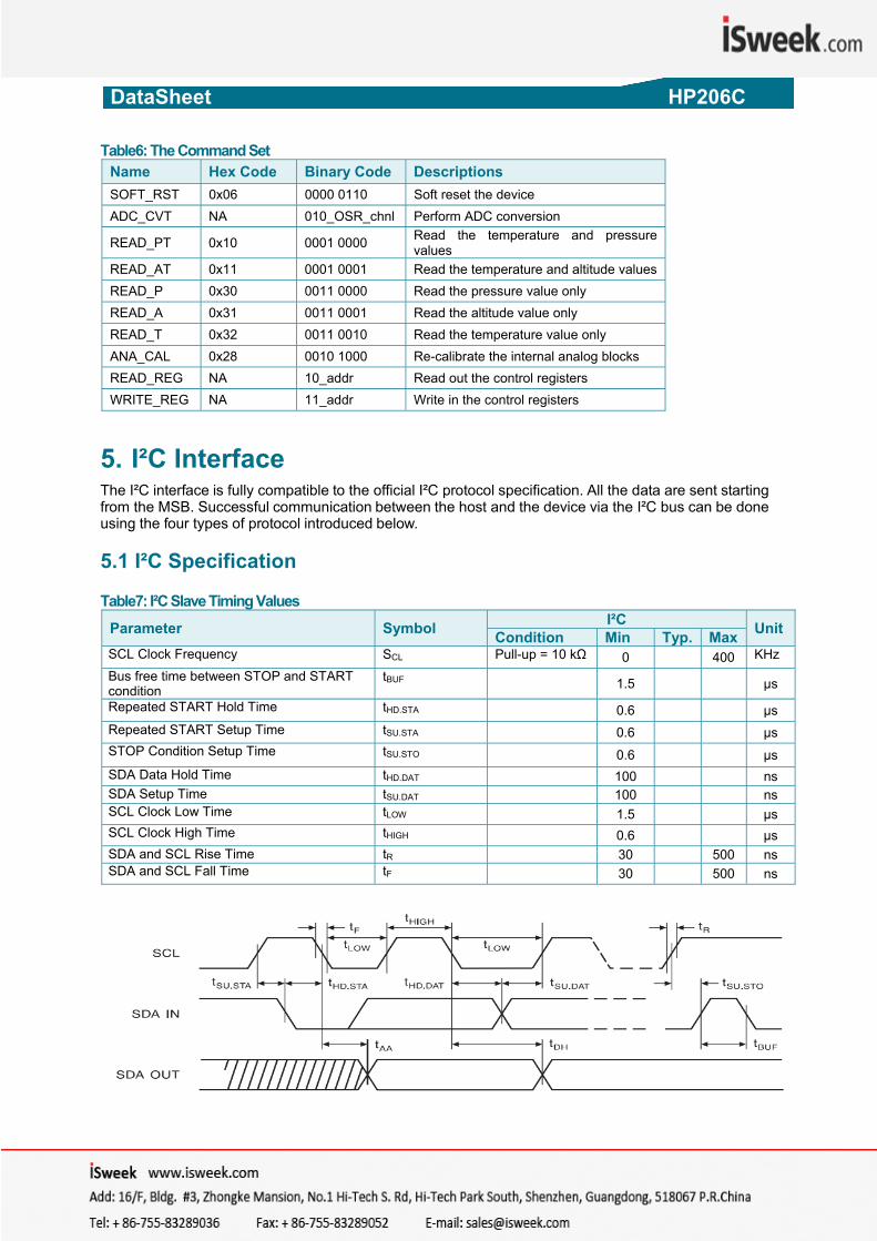
Table6: The Command Set Name Hex Code Binary Code Descriptions SOFT_RST 0x06 0000 0110 Soft reset the device ADC_CVT NA 010_OSR_chnl Perform ADC conversion
READ_PT 0x10 0001 0000 Read the temperature and pressure values
READ_AT 0x11 0001 0001 Read the temperature and altitude values READ_P 0x30 0011 0000 Read the pressure value only READ_A 0x31 0011 0001 Read the altitude value only READ_T 0x32 0011 0010 Read the temperature value only ANA_CAL 0x28 0010 1000 Re-calibrate the internal analog blocks READ_REG NA 10_addr Read out the control registers WRITE_REG NA 11_addr Write in the control registers
5. I²C Interface
The I²C interface is fully compatible to the official I²C protocol specification. All the data are sent starting from the MSB. Successful communication between the host and the device via the I²C bus can be done using the four types of protocol introduced below. 5.1 I²C Specification Table7: I²C Slave Timing Values
Parameter Symbol I²C UnitCondition Min Typ. MaxSCL Clock Frequency SCL Pull-up = 10 kΩ 0 400 KHz Bus free time between STOP and START condition
tBUF 1.5 µs
Repeated START Hold Time tHD.STA 0.6 µs Repeated START Setup Time tSU.STA 0.6 µs STOP Condition Setup Time tSU.STO 0.6 µs SDA Data Hold Time tHD.DAT 100 ns SDA Setup Time tSU.DAT 100 ns SCL Clock Low Time tLOW 1.5 µs SCL Clock High Time tHIGH 0.6 µs SDA and SCL Rise Time tR 30 500 ns SDA and SCL Fall Time tF 30 500 ns
HP206C_DataSheet_EN_V2.0 www.hoperf.com 8 / 17
DataSheet HP206C
HP206C_DataSheet_EN_V2.0 www.hoperf.com 9 / 17
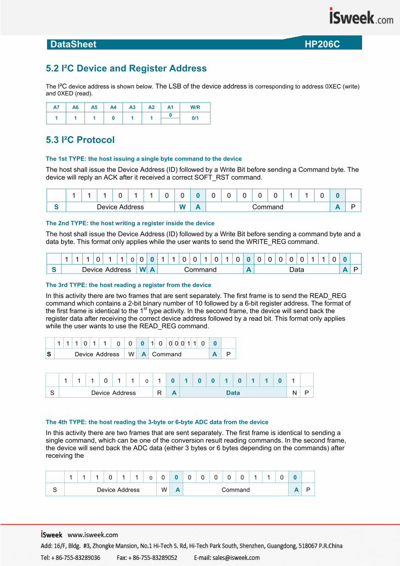
5.2 I²C Device and Register Address The I²C device address is shown below. The LSB of the device address is corresponding to address 0XEC (write) and 0XED (read).
A7 A6 A5 A4 A3 A2 A1 W/R
1 1 1 0 1 1 0 0/1
5.3 I²C Protocol The 1st TYPE: the host issuing a single byte command to the device
The host shall issue the Device Address (ID) followed by a Write Bit before sending a Command byte. The device will reply an ACK after it received a correct SOFT_RST command.
1 1 1 0 1 1 0 0 0 0 0 0 0 0 1 1 0 0
S Device Address W A Command A P The 2nd TYPE: the host writing a register inside the device
The host shall issue the Device Address (ID) followed by a Write Bit before sending a command byte and a data byte. This format only applies while the user wants to send the WRITE_REG command.
1 1 1 0 1 1 0 0 0 1 1 0 0 1 0 1 0 0 0 0 0 0 0 1 1 0 0S Device Address W A Command A Data A P
The 3rd TYPE: the host reading a register from the device
In this activity there are two frames that are sent separately. The first frame is to send the READ_REG command which contains a 2-bit binary number of 10 followed by a 6-bit register address. The format of the first frame is identical to the 1st type activity. In the second frame, the device will send back the register data after receiving the correct device address followed by a read bit. This format only applies while the user wants to use the READ_REG command.
1 1 1 0 1 1 0 0 0 1 0 0 0 0 1 1 0 0
S Device Address W A Command A P
1 1 1 0 1 1 0 1 0 1 0 0 1 0 1 1 0 1
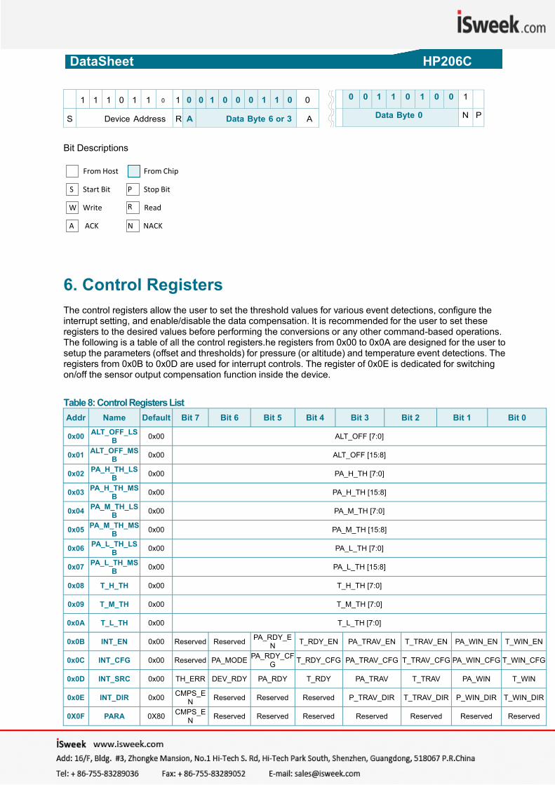
S Device Address R A Data N P The 4th TYPE: the host reading the 3-byte or 6-byte ADC data from the device
In this activity there are two frames that are sent separately. The first frame is identical to sending a single command, which can be one of the conversion result reading commands. In the second frame, the device will send back the ADC data (either 3 bytes or 6 bytes depending on the commands) after receiving the
1 1 1 0 1 1 0 0 0 0 0 0 0 0 1 1 0 0
S Device Address W A Command A P
DataSheet HP206C
1 1 1 0 1 1 0 1 0 0 1 0 0 0 1 1 0 0
S Device Address R A Data Byte 6 or 3 A
0 0 1 1 0 1 0 0 1
Data Byte 0 N P
Bit Descriptions
HP206C_DataSheet_EN_V2.0 www.hoperf.com 10 / 17
From Host
From Chip S
Start Bit
P
Stop Bit W
Write R
Read
A ACK
N
NACK
6. Control Registers The control registers allow the user to set the threshold values for various event detections, configure the interrupt setting, and enable/disable the data compensation. It is recommended for the user to set these registers to the desired values before performing the conversions or any other command-based operations. The following is a table of all the control registers.he registers from 0x00 to 0x0A are designed for the user to setup the parameters (offset and thresholds) for pressure (or altitude) and temperature event detections. The registers from 0x0B to 0x0D are used for interrupt controls. The register of 0x0E is dedicated for switching on/off the sensor output compensation function inside the device.
Table 8: Control Registers List Addr Name Default Bit 7 Bit 6 Bit 5 Bit 4 Bit 3 Bit 2 Bit 1 Bit 0
0x00 ALT_OFF_LSB 0x00 ALT_OFF [7:0]
0x01 ALT_OFF_MSB 0x00 ALT_OFF [15:8]
0x02 PA_H_TH_LSB 0x00 PA_H_TH [7:0]
0x03 PA_H_TH_MSB 0x00 PA_H_TH [15:8]
0x04 PA_M_TH_LSB 0x00 PA_M_TH [7:0]
0x05 PA_M_TH_MSB 0x00 PA_M_TH [15:8]
0x06 PA_L_TH_LSB 0x00 PA_L_TH [7:0]
0x07 PA_L_TH_MSB 0x00 PA_L_TH [15:8]
0x08 T_H_TH 0x00 T_H_TH [7:0]
0x09 T_M_TH 0x00 T_M_TH [7:0]
0x0A T_L_TH 0x00 T_L_TH [7:0]
0x0B INT_EN 0x00 Reserved Reserved PA_RDY_EN T_RDY_EN PA_TRAV_EN T_TRAV_EN PA_WIN_EN T_WIN_EN
0x0C INT_CFG 0x00 Reserved PA_MODE PA_RDY_CFG T_RDY_CFG PA_TRAV_CFG T_TRAV_CFG PA_WIN_CFG T_WIN_CFG
0x0D INT_SRC 0x00 TH_ERR DEV_RDY PA_RDY T_RDY PA_TRAV T_TRAV PA_WIN T_WIN
0x0E INT_DIR 0x00 CMPS_EN Reserved Reserved Reserved P_TRAV_DIR T_TRAV_DIR P_WIN_DIR T_WIN_DIR
0X0F PARA 0X80 CMPS_EN Reserved Reserved Reserved Reserved Reserved Reserved Reserved
DataSheet HP206C
HP206C_DataSheet_EN_V2.0 www.hoperf.com 11 / 17
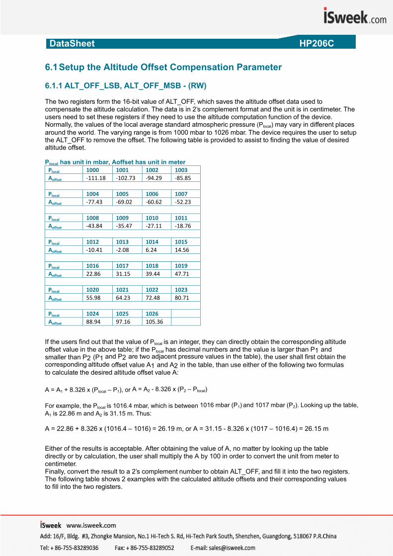
6.1 Setup the Altitude Offset Compensation Parameter 6.1.1 ALT_OFF_LSB, ALT_OFF_MSB - (RW) The two registers form the 16-bit value of ALT_OFF, which saves the altitude offset data used to compensate the altitude calculation. The data is in 2’s complement format and the unit is in centimeter. The users need to set these registers if they need to use the altitude computation function of the device. Normally, the values of the local average standard atmospheric pressure (Plocal) may vary in different places around the world. The varying range is from 1000 mbar to 1026 mbar. The device requires the user to setup the ALT_OFF to remove the offset. The following table is provided to assist to finding the value of desired altitude offset. Plocal has unit in mbar, Aoffset has unit in meter Plocal 1000 1001 1002 1003Aoffset ‐111.18 ‐102.73 ‐94.29 ‐85.85
Plocal 1004 1005 1006 1007Aoffset ‐77.43 ‐69.02 ‐60.62 ‐52.23
Plocal 1008 1009 1010 1011Aoffset ‐43.84 ‐35.47 ‐27.11 ‐18.76
Plocal 1012 1013 1014 1015Aoffset ‐10.41 ‐2.08 6.24 14.56
Plocal 1016 1017 1018 1019Aoffset 22.86 31.15 39.44 47.71
Plocal 1020 1021 1022 1023Aoffset 55.98 64.23 72.48 80.71
Plocal 1024 1025 1026 Aoffset 88.94 97.16 105.36
If the users find out that the value of Plocal is an integer, they can directly obtain the corresponding altitude offset value in the above table; if the Plocal has decimal numbers and the value is larger than P1 and smaller than P2 (P1 and P2 are two adjacent pressure values in the table), the user shall first obtain the corresponding altitude offset value A1 and A2 in the table, than use either of the following two formulas to calculate the desired altitude offset value A: A = A1 + 8.326 x (Plocal – P1), or A = A2 - 8.326 x (P2 – Plocal) For example, the Plocal is 1016.4 mbar, which is between 1016 mbar (P1) and 1017 mbar (P2). Looking up the table, A1 is 22.86 m and A2 is 31.15 m. Thus: A = 22.86 + 8.326 x (1016.4 – 1016) = 26.19 m, or A = 31.15 - 8.326 x (1017 – 1016.4) = 26.15 m Either of the results is acceptable. After obtaining the value of A, no matter by looking up the table directly or by calculation, the user shall multiply the A by 100 in order to convert the unit from meter to centimeter. Finally, convert the result to a 2’s complement number to obtain ALT_OFF, and fill it into the two registers. The following table shows 2 examples with the calculated altitude offsets and their corresponding values to fill into the two registers.
DataSheet HP206C
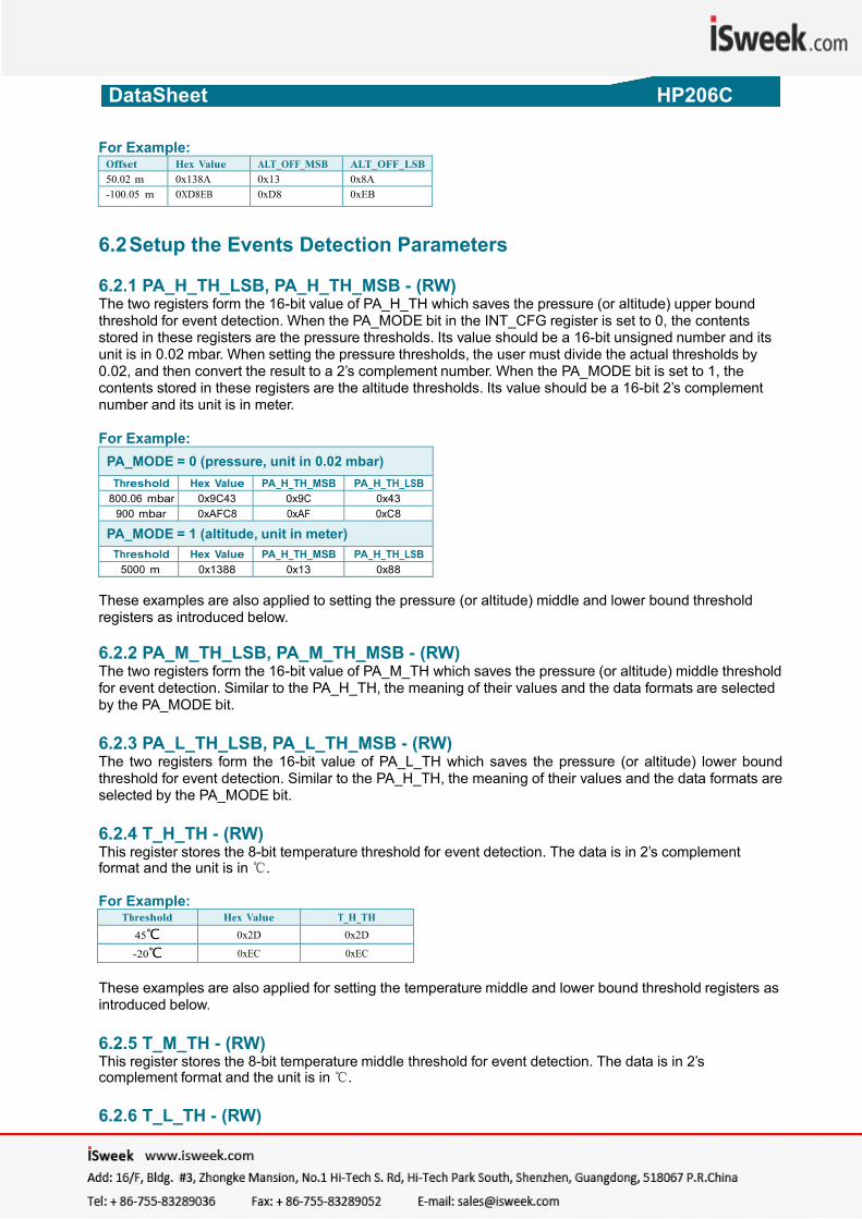
For Example: Offset Hex Value ALT_OFF_MSB ALT_OFF_LSB50.02 m 0x138A 0x13 0x8A-100.05 m 0XD8EB 0xD8 0xEB
6.2 Setup the Events Detection Parameters 6.2.1 PA_H_TH_LSB, PA_H_TH_MSB - (RW) The two registers form the 16-bit value of PA_H_TH which saves the pressure (or altitude) upper bound threshold for event detection. When the PA_MODE bit in the INT_CFG register is set to 0, the contents stored in these registers are the pressure thresholds. Its value should be a 16-bit unsigned number and its unit is in 0.02 mbar. When setting the pressure thresholds, the user must divide the actual thresholds by 0.02, and then convert the result to a 2’s complement number. When the PA_MODE bit is set to 1, the contents stored in these registers are the altitude thresholds. Its value should be a 16-bit 2’s complement number and its unit is in meter. For Example:
PA_MODE = 0 (pressure, unit in 0.02 mbar) Threshold Hex Value PA_H_TH_MSB PA_H_TH_LSB
800.06 mbar 0x9C43 0x9C 0x43900 mbar 0xAFC8 0xAF 0xC8
PA_MODE = 1 (altitude, unit in meter) Threshold Hex Value PA_H_TH_MSB PA_H_TH_LSB
5000 m 0x1388 0x13 0x88 These examples are also applied to setting the pressure (or altitude) middle and lower bound threshold registers as introduced below. 6.2.2 PA_M_TH_LSB, PA_M_TH_MSB - (RW) The two registers form the 16-bit value of PA_M_TH which saves the pressure (or altitude) middle threshold for event detection. Similar to the PA_H_TH, the meaning of their values and the data formats are selected by the PA_MODE bit. 6.2.3 PA_L_TH_LSB, PA_L_TH_MSB - (RW) The two registers form the 16-bit value of PA_L_TH which saves the pressure (or altitude) lower bound threshold for event detection. Similar to the PA_H_TH, the meaning of their values and the data formats are selected by the PA_MODE bit. 6.2.4 T_H_TH - (RW) This register stores the 8-bit temperature threshold for event detection. The data is in 2’s complement format and the unit is in .
Threshold Hex Value T_H_TH
45 0x2D 0x2D
-20 0xEC 0xEC
For Example: These examples are also applied for setting the temperature middle and lower bound threshold registers as introduced below. 6.2.5 T_M_TH - (RW) This register stores the 8-bit temperature middle threshold for event detection. The data is in 2’s complement format and the unit is in . 6.2.6 T_L_TH - (RW)
HP206C_DataSheet_EN_V2.0 www.hoperf.com 12 / 17
DataSheet HP206C
HP206C_DataSheet_EN_V2.0 www.hoperf.com 13 / 17
This register stores the 8-bit temperature lower bound threshold for event detection. The data is in 2’s complement format and the unit is in . 6.2.7 Improper Setting of Thresholds Improperly setting the thresholds, such as setting the lower bound threshold to be larger than the upper bound threshold, will lead to unexpected behavior of the device. It is recommended for the user to check the status of the TH_ERR bit in the INT_SRC register after setting the thresholds into the device. Logic 1 of this bit indicates that improper setting of the thresholds occurs. 6.3 Configure the Interrupts There are 6 interrupts that can be generated by the device. They are: 6.3.1 PA_RDY Indicates that the pressure (or altitude) measurement is done and the result is ready to read. 6.3.2 T_RDY Indicate that the temperature measurement is done and the result is ready to read. 6.3.3 PA_TRAV Indicate that the pressure (or altitude) value has traversed the middle threshold during the last measurement. 6.3.4 T_TRAV Indicate that the temperature value has traversed the middle threshold during the last measurement. 6.3.5 PA_WIN Indicate that the pressure (or altitude) value locates outside the pre-defined window (the value in between the upper bound and lower bound thresholds) during the last measurement. 6.3.6 T_WIN Indicate that the temperature value locates outside the pre-defined window (the value in between the upper bound and lower bound thresholds) during the last measurement. The interrupt names prefixed by a ‘PA’ relate to the pressure (or altitude) measurement. The interrupt names prefixed by a ‘T’ relate to the temperature measurement. These interrupts are all active-high and will remain high until the interrupt-clearing conditions happen. The interrupt-clearing conditions are that the device has received a new ADC result-reading command or a new ADC conversion command. There are three registers available for the interrupt controls as shown below. 6.3.7 INT_EN - (RW) The INT_EN register allows the user to disable/enable each of the 6 interrupts (0: disable, 1: enable). When the users need enable the traversal or window interrupt, they must also enable the corresponding PA_RDY_EN or T_RDY_EN bit.
6.3.8 INT_CFG - (RW) The INT_CFG register allows the user to select whether to output the interrupts from the INT1 pin (0: do not output, 1: output). The register also contains a control bit ‘PA_MODE’ that selects whether the event detection parameters and the interrupts registers prefixed by a ‘PA_’ corresponds to the pressure or the altitude measurement (0: pressure, 1: altitude).
6.3.9 INT_SRC - (Read-only) The INT_SRC register contains the interrupt flags that allow the user to know the interrupts status, as well as a device status bit ‘DEV_RDY’ that tells whether the device is ready for access or not. The device is ready when it is in the sleep state and is not performing the power-up sequence, the data conversions, and any other command-based operations. The external MCU shall only access to the device while the device is ready (DEV_RDY = 1). If the INT_CFG bit is set to 0 while the INT_EN bit is set to 1, the corresponding interrupt flag will appear
DataSheet HP206C
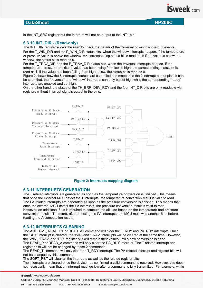
in the INT_SRC register but the interrupt will not be output to the INT1 pin. 6.3.10 INT_DIR - (Read-only) The INT_DIR register allows the user to check the details of the traversal or window interrupt events. For the T_WIN_DIR and the P_WIN_DIR status bits, when the window interrupts happen, if the temperature or pressure value is above the window, the corresponding status bit is read as 1; if the value is below the window, the status bit is read as 0. For the T_TRAV_DIR and the P_TRAV_DIR status bits, when the traversal interrupts happen, if the temperature, pressure or altitude value has been rising from low to high, the corresponding status bit is read as 1; if the value has been falling from high to low, the status bit is read as 0. Figure 2 shows how the 6 interrupts sources are controlled and mapped to the 2 interrupt output pins. It can be seen that, the “traversal” and “window” interrupts can only be set high while the corresponding “ready” interrupts are enabled and set high. On the other hand, the status of the TH_ERR, DEV_RDY and the four INT_DIR bits are only readable via registers without interrupt signals output to the pins.
Pressure or Altitude Ready Interrupt
Pressure or Altitude Traversal Interrupt
Pressure or Altitude Window Interrupt
TemperatureReady Interrupt
Temperature Traversal Interrupt
Temperature Window Interrupt
PA_RDY_EN
PA_TRAV_EN
PA_WIN_EN
T_RDY_EN
T_TRAV_EN
T_WIN_EN
PA_RDY_CFG
PA_TRAV_CFG
PA_WIN_CFG
T_RDY_CFG
T_TRAV_CFG
T_WIN_CFG
INT1
Figure 2: Interrupts mapping diagram
6.3.11 INTERRUPTS GENERATION The T related interrupts are generated as soon as the temperature conversion is finished. This means that once the external MCU detect the T interrupts, the temperature conversion result is valid to read. The PA related interrupts are generated as soon as the pressure conversion is finished. This means that once the external MCU detect the PA interrupts, the pressure conversion result is valid to read. However, an additional 5 us is required to compute the altitude based on the temperature and pressure conversion results. Therefore, after detecting the PA interrupts, the MCU must wait another 5 us before reading the A computation result. 6.3.12 INTERRUPTS CLEARING The ADC_CVT, READ_PT or READ_AT command will clear the T_RDY and PA_RDY interrupts. Once the ‘RDY’ interrupt is cleared, the ‘WIN’ and ‘TRAV’ interrupts will be cleared at the same time. However, the ‘WIN’, ‘TRAV’ and ‘DIR’ register bits will remain their values until a new conversion is done. The READ_P or READ_A command will only clear the PA_RDY interrupt. The T related interrupt and register bits will not be changed by these 2 commands. The READ_T command will only clear the T_RDY interrupt. The PA related interrupt and register bits will not be changed by this command. The SOFT_RST will clear all the interrupts as well as the related register bits. The interrupts are cleared once the device has confirmed a valid command is received. However, this does not necessarily mean that an interrupt must go low after a command is fully transmitted. For example, while
HP206C_DataSheet_EN_V2.0 www.hoperf.com 14 / 17
DataSheet HP206C
an interrupt is being cleared by an ADC reading command, it goes low while the data is being sent back from the device to the external MCU.
6.4 Enable the Compensation
PARA - (RW) This register has only one valid bit of CMPS_EN. The user can use this bit to determine whether to enable the data compensation during the conversion process (0: disable, 1: enable). If it is enabled, the 24-bit or 48-bit data read out by the commands are fully compensated. If it is disabled, the data read out are the raw data output.
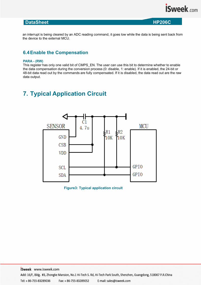
7. Typical Application Circuit
Figure3: Typical application circuit
HP206C_DataSheet_EN_V2.0 www.hoperf.com 15 / 17
DataSheet HP206C
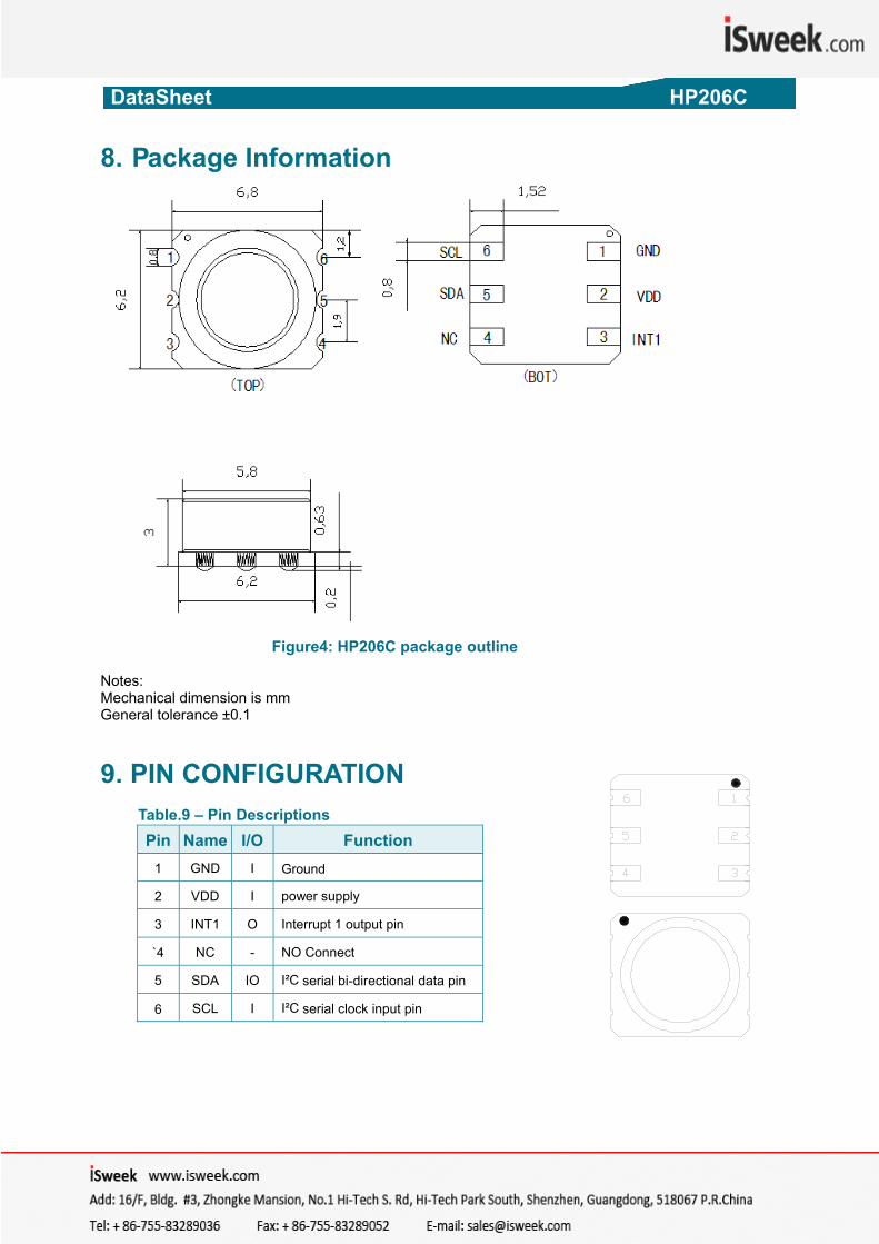
8. Package Information
Figure4: HP206C package outline
Notes: Mechanical dimension is mm General tolerance ±0.1
9. PIN CONFIGURATION
Table.9 – Pin Descriptions
Pin Name I/O Function 1 GND I Ground
2 VDD I power supply
3 INT1 O Interrupt 1 output pin
`4 NC - NO Connect
5 SDA IO I²C serial bi-directional data pin
6 SCL I I²C serial clock input pin HP206C_DataSheet_EN_V2.0 www.hoperf.com 16 / 17
DataSheet HP206C
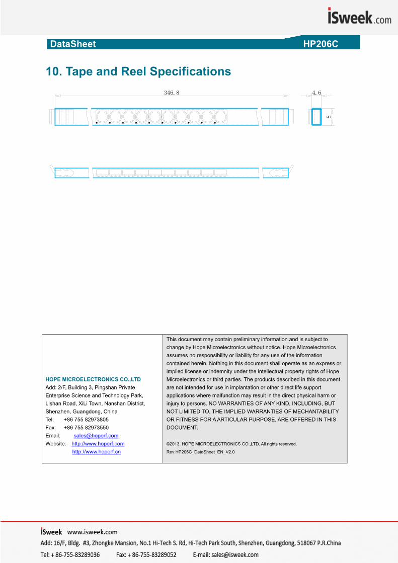
10. Tape and Reel Specifications
346.8 4.6
8
HOPE MICROELECTRONICS CO.,LTD Add: 2/F, Building 3, Pingshan Private Enterprise Science and Technology Park, Lishan Road, XiLi Town, Nanshan District, Shenzhen, Guangdong, China Tel: +86 755 82973805 Fax: +86 755 82973550 Email: [email protected] Website: http://www.hoperf.com http://www.hoperf.cn
This document may contain preliminary information and is subject to change by Hope Microelectronics without notice. Hope Microelectronics assumes no responsibility or liability for any use of the information contained herein. Nothing in this document shall operate as an express or implied license or indemnity under the intellectual property rights of Hope Microelectronics or third parties. The products described in this document are not intended for use in implantation or other direct life support applications where malfunction may result in the direct physical harm or injury to persons. NO WARRANTIES OF ANY KIND, INCLUDING, BUT NOT LIMITED TO, THE IMPLIED WARRANTIES OF MECHANTABILITY OR FITNESS FOR A ARTICULAR PURPOSE, ARE OFFERED IN THIS DOCUMENT. ©2013, HOPE MICROELECTRONICS CO.,LTD. All rights reserved.
Rev:HP206C_DataSheet_EN_V2.0
HP206C_DataSheet_EN_V2.0 www.hoperf.com 17 / 17