power ware 9315
TRANSCRIPT

InstallationManual
Uninterruptible PowerSupply
100 kVA -- 160 kVA
164200292 Rev. E
9315

ii Powerware 9315 (100 kVA--160 kVA) Installation164200292 REV. E 041500
------------------------------------------------------------------------------------------------------------------------------------------------
----------------------------------
IMPORTANT SAFETY INSTRUCTIONS
Instructions Importantes Concernant La Sécurité
SAVE THESE INSTRUCTIONS
Conserver Ces Instructions
This manual contains important instructions for your Uninterruptible PowerSupply (UPS) system. You should follow these instructions during the
installation and maintenance of the UPS, options, accessories, and batteries.
Cette notice contient des instructions importantesconcernant la sécurité.
This equipment has been tested and found to comply with the limits for a Class Adigital device, pursuant to Part 15 of the FCC Rules. These limits are designed toprovide reasonable protection against harmful interference when the equipment isoperated in a commercial environment. This equipment generates, uses, and canradiate radio frequency energy and, if not installed and used in accordance withthe instruction manual, may cause harmful interference to radio communications.Operation of this equipment in a residential area is likely to cause harmfulinterference in which case the user will be required to correct the interference attheir own expense.
WARNING:This is a product for restricted sales distribution to informed partners. Installationrestrictions or additional measures may be needed to prevent disturbances.

iiiPowerware 9315 (100 kVA--160 kVA) Installation164200292 Rev. E 041500
Table of Contents
1 Introduction 1. . . . . . . . . . . . . . . . . . . . . . . . . . . . . . . . . . . . . . . . . . . .
Using This Manual 2. . . . . . . . . . . . . . . . . . . . . . . . . . . . . . . . . . . . . . . . . . . .
Conventions Used in This Manual 3. . . . . . . . . . . . . . . . . . . . . . . . . . . . . . .
For More Information 3. . . . . . . . . . . . . . . . . . . . . . . . . . . . . . . . . . . . . . . . . .
Getting Help 3. . . . . . . . . . . . . . . . . . . . . . . . . . . . . . . . . . . . . . . . . . . . . . . . . .
2 Getting Started 5. . . . . . . . . . . . . . . . . . . . . . . . . . . . . . . . . . . . . . . . .
Preparing Your Site 6. . . . . . . . . . . . . . . . . . . . . . . . . . . . . . . . . . . . . . . . . . . .
Environment Considerations 6. . . . . . . . . . . . . . . . . . . . . . . . . . . . . . . . . . .
Preparing for Wiring the UPS System 6. . . . . . . . . . . . . . . . . . . . . . . . . . . .
Inspecting and Unpacking Each Cabinet 7. . . . . . . . . . . . . . . . . . . . . . . . .
Unloading the UPS Cabinet From the Pallet 8. . . . . . . . . . . . . . . . . . . . . .
Creating an Installation Plan 10. . . . . . . . . . . . . . . . . . . . . . . . . . . . . . . . . . . .
3 Installing the UPS 11. . . . . . . . . . . . . . . . . . . . . . . . . . . . . . . . . . . . . . .
Preparing the UPS for InstallingOptional Cabinets or Accessories 13. . . . . . . . . . . . . . . . . . . . . . . . . . . .
Completing the Installation Checklist 15. . . . . . . . . . . . . . . . . . . . . . . . . . . .
Installation Checklist 16. . . . . . . . . . . . . . . . . . . . . . . . . . . . . . . . . . . . . . . . . .
Notes 17. . . . . . . . . . . . . . . . . . . . . . . . . . . . . . . . . . . . . . . . . . . . . . . . . . . . . . .
4 Joining Cabinets 19. . . . . . . . . . . . . . . . . . . . . . . . . . . . . . . . . . . . . . .
Method A --- Joining an Optional Cabinet to the UPS 20. . . . . . . . . . . . . .
Method B --- Joining Optional Cabinets to Each Other 23. . . . . . . . . . . . .
Grounding Joined Cabinets 25. . . . . . . . . . . . . . . . . . . . . . . . . . . . . . . . . . . .
Method A Grounding 25. . . . . . . . . . . . . . . . . . . . . . . . . . . . . . . . . . . . . . . . . .
Method B Grounding 25. . . . . . . . . . . . . . . . . . . . . . . . . . . . . . . . . . . . . . . . . .
5 Installing Battery Cabinets 27. . . . . . . . . . . . . . . . . . . . . . . . . . . . . .
Two Models are Available 27. . . . . . . . . . . . . . . . . . . . . . . . . . . . . . . . . . . . . .
Important Safety Instructions 27. . . . . . . . . . . . . . . . . . . . . . . . . . . . . . . . . . .
General Notes About Installing Battery Cabinets andRemote Disconnects 28. . . . . . . . . . . . . . . . . . . . . . . . . . . . . . . . . . . . . . .

iv Powerware 9315 (100 kVA--160 kVA) Installation164200292 REV. E 041500
6 Installing an Input Transformer 29. . . . . . . . . . . . . . . . . . . . . . . . . .
7 Installing a Power Distribution Module 33. . . . . . . . . . . . . . . . . . .
8 Installing a Remote EPO Control 37. . . . . . . . . . . . . . . . . . . . . . . . .
9 Installing a Remote Battery Disconnect 39. . . . . . . . . . . . . . . . . .
10 Installing a Remote Monitor Panel 41. . . . . . . . . . . . . . . . . . . . . .
11 Installing a Relay Interface Module 47. . . . . . . . . . . . . . . . . . . . .
12 Installing a Supervisory Contact 51. . . . . . . . . . . . . . . . . . . . . . . .
Appendix A --- Customer Information A---1. . . . . . . . . . . . . . . . . . . . . . . . . .Powerware 9315 (100 kVA--160 kVA) Installation
164200292 REV. E 041500

vPowerware 9315 (100 kVA--160 kVA) Installation164200292 Rev. E 041500
List of Figures
Figure 1. Typical UPS System 1. . . . . . . . . . . . . . . . . . . . . . . . . . . . . . . . . . . .
Figure 2. Cabinet as Shipped, with Outer Packaging and Pallet 7. . . . . .
Figure 3. Removing Front and Rear Supports 9. . . . . . . . . . . . . . . . . . . . . .
Figure 4. UPS Cabinet 11. . . . . . . . . . . . . . . . . . . . . . . . . . . . . . . . . . . . . . . . . .
Figure 5. Preparing the UPS for Installing Other Cabinets 14. . . . . . . . . . . .
Figure 6. Methods of Joining Cabinets 19. . . . . . . . . . . . . . . . . . . . . . . . . . . .
Figure 7. Joining an Optional Cabinet to the UPS 20. . . . . . . . . . . . . . . . . . .
Figure 8. Pushing Cabinets Together 20. . . . . . . . . . . . . . . . . . . . . . . . . . . . . .
Figure 9. Placement of Joining Brackets 21. . . . . . . . . . . . . . . . . . . . . . . . . . .
Figure 10. Installing the Angled Bracket 22. . . . . . . . . . . . . . . . . . . . . . . . . . .
Figure 11. Preparing to Join Component Cabinets 23. . . . . . . . . . . . . . . . . .
Figure 12. Joining Component Cabinets 24. . . . . . . . . . . . . . . . . . . . . . . . . .
Figure 13. Cabinet-to-Cabinet Grounding --- Method A 26. . . . . . . . . . . . . .
Figure 14. Cabinet-to-Cabinet Grounding --- Method B 26. . . . . . . . . . . . . .
Figure 15. Input Transformer Cabinet 29. . . . . . . . . . . . . . . . . . . . . . . . . . . . .
Figure 16. Installing an Input Transformer Cabinet 31. . . . . . . . . . . . . . . . . .
Figure 17. Typical PDM Cabinet 33. . . . . . . . . . . . . . . . . . . . . . . . . . . . . . . . . .
Figure 18. Remote EPO Control 37. . . . . . . . . . . . . . . . . . . . . . . . . . . . . . . . . .
Figure 19. Remote Battery Disconnect Enclosure 39. . . . . . . . . . . . . . . . . . .
Figure 20. Remote Monitor Panel (RMP) 42. . . . . . . . . . . . . . . . . . . . . . . . . . .
Figure 21. Terminal Block Bracket 43. . . . . . . . . . . . . . . . . . . . . . . . . . . . . . . .
Figure 22. Wiring an RMP to the UPS 44. . . . . . . . . . . . . . . . . . . . . . . . . . . . .
Figure 23. Relay Interface Module 47. . . . . . . . . . . . . . . . . . . . . . . . . . . . . . . .
Figure 24. Terminal Block Bracket 48. . . . . . . . . . . . . . . . . . . . . . . . . . . . . . . .
Figure 25. Wiring an RIM to the UPS 48. . . . . . . . . . . . . . . . . . . . . . . . . . . . . .
Figure 26. Supervisory Contact Module 51. . . . . . . . . . . . . . . . . . . . . . . . . . .
Figure 27. Terminal Block Bracket 52. . . . . . . . . . . . . . . . . . . . . . . . . . . . . . . .
Figure 28. Wiring an SCM to the UPS 52. . . . . . . . . . . . . . . . . . . . . . . . . . . . .
Figure 29. Supervisory Contact Module TB2 54. . . . . . . . . . . . . . . . . . . . . . .

vi Powerware 9315 (100 kVA--160 kVA) Installation164200292 REV. E 041500
This Page Intentionally Left Blank.

1Powerware 9315 (100 kVA--160 kVA) Installation164200292 Rev. E 041500
Introduction
This manual describes how to install your Powerware 9315Uninterruptible Power Supply (UPS) system. It contains instructions for
installing the UPS and each optional component and accessory. The informationyou will use depends on the system you purchased.
Each component of your UPS system is housed in a free-standing cabinet. Thecabinets line up and match in style and color, and have safety shields behind thedoors for hazardous voltage protection. Figure 1 shows a sample UPS system thatincludes at least one of each component.
(optional)
PDM CABINET(optional)
INPUTTRANSFORMERCABINET
CABINETUPS
CABINETBATTERY
(up to four)
Figure 1. Typical UPS System
These basic UPS system configurations are possible:
� The UPS and one or more battery cabinets
� The UPS, battery cabinet(s), and a Power Distribution Module (PDM)
� The UPS, battery cabinet(s), and an input transformer
� The UPS, battery cabinet(s), PDM, and input transformer.
You can enhance any of these system configurations by adding optional accessories,such as a Remote Monitor Panel (RMP), Relay Interface Module (RIM), or RemoteEmergency Power Off (EPO) control.

2 Powerware 9315 (100 kVA--160 kVA) Installation164200292 REV. E 041500
Using This Manual
The system you are installing dictates which parts of this manual you should read.Everyone should read Chapters 1 through 4:
� Chapter 1 discusses installation considerations for your entire UPS system.
� Chapter 2 tells you how to prepare your site for the installation of your UPSsystem. It discusses equipment environmental requirements, inspecting andunpacking cabinets, and pallet removal.
� Chapter 3 describes how to install the UPS cabinet.
� Chapter 4 illustrates the two methods for joining cabinets together.
� Chapter 5 contains safety instructions and general notes for installation of theUPS manufacturer’s optional battery cabinets.
� Chapter 6 contains information for installing the optional input transformercabinet.
� Chapter 7 contains information for installing the optional Power DistributionModule (PDM).
� Chapter 8 discusses installing the optional Remote Emergency Power Off(EPO) control.
� Chapter 9 contains information for installing the optional remote batterydisconnect.
� Chapter 10 contains information for installing the optional Remote MonitorPanel (RMP).
� Chapter 11 contains information for installing the optional Relay InterfaceModule (RIM).
� Chapter 12 contains information for installing the optional Supervisory ContactModule (SCM).
� Appendix A contains important information for planning and installing your UPSsystem, including illustrations of cabinets and optional accessories.
Read through each installation procedure before you begin. Perform only thoseprocedures that apply to the UPS system you are installing.

3Powerware 9315 (100 kVA--160 kVA) Installation164200292 Rev. E 041500
Conventions Used in This Manual
The text in this manual uses these conventions:
� Bold type highlights important concepts in discussions, key terms inprocedures, and menu options.
� Italic type highlights notes and new terms where they are defined.
� Rectangular boxes containing bold type are warnings or cautions that pertain tothe UPS system or its electrical connections.
In this manual, the term UPS refers only to the UPS cabinet and its internal elements.The term UPS system refers to the entire power protection system—the UPS cabinetplus any options or accessories you have installed.
For More Information
This manual describes how to install your UPS system. For more informationabout the operation and communications capabilities of the UPS system, refer tothe following:
164200252 Powerware 9315 30 kVA---160 kVA UPS Operation
Describes the UPS cabinet Control Panel and Monitor Panel, andexplains the functions of the UPS; discusses the standardfeatures of the UPS and optional accessories; providesprocedures for starting and stopping the UPS, and informationabout maintenance and responding to system events.
Also described are the RS---485 and RS---232 serialcommunications capabilities of the UPS system; discusses thetwo communications ports on the Customer Interface Panelinside the UPS and how to connect optional remote accessoriesto your UPS system; provides information about enabling,disabling, and customizing building alarms.
Contact your local Field Service office for information on how to obtain copies ofthis manual.
Getting Help
If you have a question about any of the information in this manual, or if you have aquestion this manual does not answer, please call Powerware Corporation FieldService:
United States 1-800-843-9433
Canada 1-800-461-9166
Outside the U.S. Call your local representative

4 Powerware 9315 (100 kVA--160 kVA) Installation164200292 REV. E 041500
This Page Intentionally Left Blank.

5Powerware 9315 (100 kVA--160 kVA) Installation164200292 Rev. E 041500
Getting Started
Each cabinet of your UPS system is shipped on a separate pallet. Use aforklift or pallet jack to move the packaged cabinets to the installation site, or
as close as possible to the site, before you unload them from the pallets.
This is the basic sequence of the installation steps:
1. Prepare your site for the UPS cabinet (Chapter 2).
2. Inspect, unpack, and unload the UPS cabinets (Chapter 2).
3. Create an installation plan for the UPS and optional cabinets (Chapter 3).
4. Join the cabinets together using supplied hardware (Chapter 4).
5. Wire the cabinets together (Chapters 5---12, as applicable).
6. Install features, accessories, and/or options (Chapters 5---12, as applicable).
7. Complete the Installation Checklist (Chapter 3).
8. Have authorized service personnel perform preliminary checks and startup.
After wiring the UPS system to the facility power and critical load(s), be sure to groundthe system according to local and/or national electrical wiring codes, using your owncabling and conduit.
Install batteries in accordance with all applicable codes and regulations, including theNational Electrical Code (NEC), Article 480.
NOTE: Startup and operational checks should be performed only by authorizedservice personnel. This service is usually offered as part of the salescontract for your UPS system.

6 Powerware 9315 (100 kVA--160 kVA) Installation164200292 REV. E 041500
Preparing Your Site
For your UPS system to operate at peak efficiency, your installation site shouldmeet the environmental parameters outlined in the operator’s manual for the UPS.If you intend to operate the UPS at an altitude higher than 1500 meters (5000 feet),contact your local sales or service office for important information about highaltitude operation. The operating environment must meet the size and weightrequirements shown in Table R of Appendix A.
The basic environmental requirements for operation of the UPS system are:
Ambient Temperature Range: 0---40˚ C (32---104˚ F)
Recommended Operating Range: 20---25˚ C (68---77˚ F)
Maximum Relative Humidity: 95%
The UPS cabinet uses forced air cooling to regulate internal component temperature.The battery and optional component cabinets use convection cooling to regulateinternal component temperature. Air inlets are in the front of the cabinet, and outletsare in the top. You must allow clearance in front of and above each cabinet for properair circulation.
Environment Considerations
The life of the UPS system will be adversely affected if the installation does notmeet the following guidelines:
1. The UPS system must be installed on a sealed concrete pad on a sealedconcrete floor.
2. The UPS system must be installed in a dust-free environment.
3. The UPS system must be installed in a humidity-controlled environment.
Preparing for Wiring the UPS System
For external wiring requirements, including the minimum AWG size of externalwiring, see Tables J through L in Appendix A. The power wiring for this equipmentis rated at 75˚C. If wire is run in an ambient temperature greater than 30˚C, highertemperature and/or larger size wire may be necessary. Wiring for optionalaccessories (such as a Remote Monitor Panel (RMP) or Relay Interface Module(RIM)) should be installed through the 28.6 mm (1.1 in.) knockout in the bottom ofthe UPS cabinet. The top entry connection requires installation of ½-in. flexibleconduit within the UPS. Bottom entry connection requires no additional routing ofconduit within the UPS.

7Powerware 9315 (100 kVA--160 kVA) Installation164200292 Rev. E 041500
Inspecting and Unpacking Each Cabinet
The first task in preparing for installation is inspecting and unpacking each cabinet.Cabinets arrive covered with protective packaging material as shown in Figure 2.
FOAM CUSHION
OUTERPACKAGING
Figure 2. Cabinet as Shipped, with Outer Packaging and Pallet
1. Carefully inspect the outer packaging for evidence of damage during transit.
CAUTION:Do not install a damaged cabinet. Report any damage to the carrier andcontact your local sales or service office immediately.
2. Use a forklift or other material handling equipment to move the cabinet to aconvenient unpacking area. Insert the forklift jacks between the foam cushionson the bottom of the unit.
CAUTION:Do not tilt cabinets more than 10 degrees from vertical.

8 Powerware 9315 (100 kVA--160 kVA) Installation164200292 REV. E 041500
3. Set each pallet on a firm, level surface, allowing a minimum clearance of4.6m (15 ft) on each side for removing the cabinets from the pallets.
4. Cut the steel bands around each cabinet.
5. Remove the protective cardboard covering from the cabinets, cutting whereindicated, using a knife blade no longer than 25 mm (1 in.).
NOTE: Do not discard the packaging material yet. Instructions for unloading thecabinet from the pallet are printed on the cardboard, and you will need torefer to them.
6. Remove the plastic bag and foam packing material, and discard or recyclethem in a responsible manner.
Unloading the UPS Cabinet From the Pallet
The UPS cabinet is bolted to a sheet metal pallet consisting of four supports securedto foam cushions. The foam cushions act as shock absorbers for the cabinet duringshipment.
WARNING:UPS cabinets are extremely heavy. If unloading instructions are notclosely followed, the cabinet may tip and cause serious injury.
Turning the jacking bolts unevenly may cause the cabinet to becomeunbalanced. To prevent tipping, raise and lower the jacking boltsevenly. The cabinet should only be raised approximately 3 mm (1/8 in.)above the floor (just enough to remove foam cushions).
1. Remove the doors. Remove the retaining screw located inside each door atthe bottom hinge pivot point, then lift the door off. Save the retaining screwsfor reinstallation of the doors.
2. Locate the field kit (packed inside of the cabinet or communications panel).Locate the four ½-in. jacking bolts and install them in the threaded holes in thefront and rear supports. Place a floor protector underneath each jacking bolt,and screw the bolts down against them. The floor protectors will save the floorfrom being marred by the jacking bolts.
3. Loosen, but do not remove the hardware holding the foam cushions to thefront and rear supports (labeled “1” in Figure 3).
4. Turn each jacking bolt consecutively, two full turns, until the foam cushionsclear the floor by approximately 3 mm (1/8 in.).
5. After the foam cushions clear the floor, remove the hardware loosened instep 3. Pull the foam cushions out from under the UPS cabinet, and discard orrecycle them in a responsible manner.

9Powerware 9315 (100 kVA--160 kVA) Installation164200292 Rev. E 041500
FRONTSIDE
FOAM
SUPPORTSUPPORT
1
2
1
2
2
JACKINGBOLT
FLOOR
PROTECTOR
1
2
LEFT HAND
DOOR
CUSHION
Figure 3. Removing Front and Rear Supports
WARNING:Cabinet may fall. Do not loosen hardware attaching the side or frontsupports to the cabinet base. Also, do not loosen supports from eachother. The cabinet must be lowered using jacking bolts before supportscan be removed.
6. Carefully and evenly lower the cabinet by turning each jacking boltconsecutively two full turns (maximum) until the supports contact the floor, andthe cabinet is no longer supported by the jacking bolts.
7. After the UPS cabinet is resting on the floor, remove the jacking bolts anddiscard or recycle them in a responsible manner.
8. Remove the hardware labeled “2” in Figure 3, holding the front, rear and sidesupports to the cabinet base. Discard or recycle the hardware and supportbrackets in a responsible manner.
9. Replace the doors removed in step 1. The UPS cabinet is now ready to berolled to its final location.
10. Repeat steps 1 through 9 for each cabinet you are preparing to install.

10 Powerware 9315 (100 kVA--160 kVA) Installation164200292 REV. E 041500
Creating an Installation Plan
Before beginning to install your UPS system, you should be sure you understandthe portions of this manual that apply to your system. Use the procedures andillustrations in the following sections to create a logical plan for installing the UPSand optional components. The information in Chapter 3 will help you plan theinstallation.

11Powerware 9315 (100 kVA--160 kVA) Installation164200292 Rev. E 041500
Installing the UPS
After you unpack, inspect, and move your UPS to its installed location, youare ready to prepare for installation. The UPS cabinet arrives as shown in
Figure 4.
COOLINGAIR INLETS
TOPWIREENTRY
COOLINGAIR EXHAUST
BOTTOMWIREENTRY
TOP VIEW
BOTTOM VIEW
Figure 4. UPS Cabinet

12 Powerware 9315 (100 kVA--160 kVA) Installation164200292 REV. E 041500
Refer to the following while installing the UPS:
� Dimensions in this manual are in millimeters and inches.
� Do not tilt the UPS or other cabinets more than 10˚ during installation.
� Cooling exhaust airflow is approximately 920.0 L/S (1950 CFM).
� The conduit landing plates are to be removed to add conduit landing holes asrequired. Plate material is 16 gauge steel (0.06 in. thick).
� Terminals E1–E15 are UL and CSA rated at 90˚C. A hex key tool is required toattach wires to the terminals.
� The Remote Emergency Power Off (EPO) feature opens all breakers andcontactors in the UPS cabinet and isolates power from your critical load. Localelectrical codes may also require tripping upstream protective devices to theUPS.
� If perforated floor tiles are required for ventilation, place them in front of theUPS. Refer to Table R in Appendix A for equipment weight and point loading.
� Details about control wiring are provided in each procedure for connectingoptions and features. Table U in Appendix A identifies the control wiringterminations.
� Refer to the Powerware 9315 Maintenance Bypass Module (MBM) Installationand Operation Manual 164201177 for MBM installation.

13Powerware 9315 (100 kVA--160 kVA) Installation164200292 Rev. E 041500
Preparing the UPS for InstallingOptional Cabinets or Accessories
If you are installing optional cabinets or accessories, such as a Power DistributionModule (PDM) cabinet, an input transformer cabinet, or a Remote Monitor Panel(RMP), you must prepare the UPS cabinet for the installation of these options.Refer to Figure 5 for the locations of the items mentioned in these procedures.Also, refer to Powerware 9315 Series 685 and 1085 Auxiliary Battery CabinetsInstallation Manual, 164200300, for information on installing battery cabinets.
To prepare the UPS for joining to an input transformer, PDM, or both:
1. Be sure the UPS is turned off and all power sources are removed. (See theoperator’s manual for instructions.)
2. Remove the left side panel of the UPS and set it aside.
3. Open the doors of the UPS.
4. Remove the air filters and set aside for later reuse.
5. Remove the lower metal access panel (see Figure 5 for location). Set theaccess panel and hardware aside for later reuse.
To prepare the UPS for wiring to an RMP, RIM, SCM, or Remote EPO:
1. Be sure the UPS is turned off and all power sources are removed. (See theoperator’s manual for instructions.)
2. Open the doors of the UPS.
3. Remove the air filters and set aside for later reuse.
4. Remove the lower metal access panel (see Figure 5 for location). Set theaccess panel and hardware aside for later reuse.

14 Powerware 9315 (100 kVA--160 kVA) Installation164200292 REV. E 041500
RIGHT SIDE PANEL
LEVELING FEET
SIDE PANELMOUNTING SCREWS
LEFT SIDE PANEL
BATTERY BREAKERSENSING CABLE
BATTERY POWERCONNECTOR
TB1 TB2
UPPERRIGHT-HANDACCESS PANEL
LOWERACCESSPANELAND
AIR FILTERS
LEFT DOOR
(REMOVED)
(REMOVED)
COMMUNICATIONPANEL
NOTE: UPS Shown with Right Door Open or Removed
Figure 5. Preparing the UPS for Installing Other Cabinets

15Powerware 9315 (100 kVA--160 kVA) Installation164200292 Rev. E 041500
Completing the Installation Checklist
The final step in installing your UPS system is completing the following InstallationChecklist. This checklist ensures that you have completely installed all hardware,cables, and other equipment. Completing all items listed on the checklist willensure a smooth installation. You should make a copy of the Installation Checklistbefore filling it out, and retain the original.
After your installation is complete, a service representative will be able to verify theoperation of your UPS system and commission it to support your critical load. Theservice representative cannot perform any installation tasks other than verifyingsoftware and operating setup parameters. Service personnel may request a copyof the completed Installation Checklist to be sure you have completed allapplicable equipment installation.
NOTE: The Installation Checklist MUST be completed prior to starting the UPSsystem for the first time.

16 Powerware 9315 (100 kVA--160 kVA) Installation164200292 REV. E 041500
Installation Checklist
-All packing materials and restraints have been removed from each cabinet.
-Each cabinet in the UPS system is placed in its installed location.
-All cabinets (except stand-alone cabinets) are bolted together.
-A ground bond is installed between all cabinets that are bolted together.
-All switchboards, conduits, and cables are properly routed to the UPS and auxiliarycabinets.
-Power cables are terminated on bypass terminals (E6---E8 on 480V systems, E13---E15on all other systems).
-Power cables are terminated on the CB1 input breaker (E1---E3 on 480V systems,E13---E15 on all other systems).
-A ground conductor is properly installed.
-If neutral connection is used, no other N---G bonds exist downstream from the UPS.
-Battery cables and harness are terminated on the K2 battery contactor E4 and E5.
-Internal battery cabinet connections have been completed (bus bars, plugs, etc.).
-Air conditioning equipment is installed and operating correctly.
-The area around the installed UPS system is clean and dust-free. (It is recommendedthat the UPS be installed on a sealed concrete pad on a sealed concrete floor.)
-Adequate workspace exists around the UPS and other cabinets.
-Adequate lighting is provided around all UPS equipment.
-A 120V service outlet is located within 25 feet of the UPS equipment.
-Each Remote Monitor Panel (RMP) is mounted in its installed location. (OPTIONAL)
-The control wiring for each RMP is terminated inside the UPS cabinet. (OPTIONAL)
-The Remote Emergency Power Off (EPO) device is mounted in its installed locationand its wiring terminated inside the UPS cabinet. (OPTIONAL)
-Summary alarms and/or building alarms are wired appropriately. (OPTIONAL)
-A Relay Interface Module (RIM) is mounted in its installed location and its wiring isterminated inside the UPS cabinet. (OPTIONAL)
-A remote battery disconnect control is mounted in its installed location and its wiring isterminated inside the UPS and battery cabinet. (OPTIONAL)

17Powerware 9315 (100 kVA--160 kVA) Installation164200292 Rev. E 041500
Notes
________________________________________________________________________________
________________________________________________________________________________
________________________________________________________________________________
________________________________________________________________________________
________________________________________________________________________________
________________________________________________________________________________
________________________________________________________________________________
________________________________________________________________________________
________________________________________________________________________________
________________________________________________________________________________
________________________________________________________________________________
________________________________________________________________________________
________________________________________________________________________________

18 Powerware 9315 (100 kVA--160 kVA) Installation164200292 REV. E 041500
This Page Intentionally Left Blank.

19Powerware 9315 (100 kVA--160 kVA) Installation164200292 Rev. E 041500
Joining Cabinets
The method you use to join two cabinets depends on whichcabinets they are. For the purpose of discussion, this chapter uses the term
UPS to refer to the UPS cabinet, and the term optional cabinet to refer to any othercabinet (such as an input transformer or PDM cabinet). There are two differentprocedures for joining the cabinets in your UPS system:
� Method A --- Joining an optional cabinet to the UPS
� Method B --- Joining two optional cabinets to each other
Figure 6 shows which method you should use for each cabinet. The UPS systemshown in Figure 6 includes a UPS and one of each optional cabinet. As the figureshows, you should remove the cosmetic covers from the sides of all cabinets exceptthe outermost right and left cabinets of a line-up-and-match system.(Do not remove the cosmetic covers from the sides of stand-alone cabinets.)
PDM CABINET
INPUT TRANSFORMER
UPS CABINET
Method
Method
A
B
CABINET
Figure 6. Methods of Joining Cabinets
Use the appropriate method to join each cabinet in the position shown in Figure 6:
� Use Method A to join the input transformer cabinet to the left side of the UPScabinet.
� Use Method B to join the PDM cabinet to the left side of the input transformercabinet (if present). If you do not have an input transformer cabinet, useMethod A to join the PDM cabinet to the left side of the UPS cabinet.
� Refer to Powerware 9315 Series 685 and 1085 Auxiliary Battery CabinetsInstallation Manual, 164200300, for procedures to connect battery cabinets.

20 Powerware 9315 (100 kVA--160 kVA) Installation164200292 REV. E 041500
Method A --- Joining an Optional Cabinet to the UPS
Use this procedure to join any optional cabinet to the UPS:
1. Secure the UPS with its leveling feet.
2. Roll the optional cabinet to a spot near the UPS, in any one of the threepositions shown in Figure 7. A PDM or input transformer cabinet should bejoined to the left side of the UPS.
FRONT
Leftside
Rightside
Figure 7. Joining an Optional Cabinet to the UPS
3. Remove the cosmetic covers from the two cabinet sides you are joining.
4. Push the optional cabinet toward the UPS cabinet until both cabinets arealigned at the rear. Figure 8 shows two optional cabinets pushed into placeand aligned with the rear of the UPS cabinet.
PUSH
PUSH
PUSH
FRONT
Figure 8. Pushing Cabinets Together
5. Three cabinet joining brackets are provided for securing each cabinet at thetop and bottom. Two flat brackets connect the tops of the cabinets, one at thefront and one at the back. The bottom bracket type is dependent on cabinetconfiguration. See Figure 9 and Figure 10. Either an angled bracket or alarger flat bracket joins the cabinets at the bottom. Attach the flat brackets tothe cabinet tops first.

21Powerware 9315 (100 kVA--160 kVA) Installation164200292 Rev. E 041500
NOTE: The following steps describe how to join an optional cabinet to the left sideof the UPS.
6. Remove the screw from the top door hinge of the UPS cabinet. Remove thehex head screw from the front hole in the top frame angle on the optionalcabinet. Align the small hole in one flat bracket over the screw hole in thecabinet hinge, and the large hole over the hole in the optional cabinet frame.Install the screws (see Figure 9).
(see detail at left)
OPTIONALCABINET
CABINETUPS
Angled bracket goes here
CABINETUPS
(top view)
OPTIONALCABINET(top view)
Two flat brackets go here
FRONT
BACK
FRONT
BACK
(see Figure 10)
Existing screwScrew from kit
Existing Screw
Figure 9. Placement of Joining Brackets
NOTE: When cabinets are properly aligned, all cabinet doors will be flush with eachother.
7. Use the same method as step 6 to install the second flat bracket over thescrews at the rear of the cabinet tops.
8. Remove the nut from the screw in the lower door hinge of the UPS cabinet.

22 Powerware 9315 (100 kVA--160 kVA) Installation164200292 REV. E 041500
9. Hold the angled bracket parallel to the floor (see Figure 10). The flange withthe hole in it (labeled A in Figure 10) should be facing upward. The flange withthe tab (labeled B in Figure 10) should be pointing toward the slot in the baseof the optional cabinet.
Lowerdoor hinge
Figure 10. Installing the Angled Bracket
10. Insert the tab (B) into the slot in the base of the optional cabinet.
11. Slide the bracket toward the UPS cabinet while slipping the hole (A) onto thescrew in the lower door hinge of the UPS cabinet.
12. Install the nut (removed in step 8) on the hinge screw to secure the angledbracket in place.
13. Repeat steps 2 through 12 to join another optional cabinet to the other side ofthe UPS cabinet.
14. Attach a ground wire to the joined cabinets using the procedure “GroundingJoined Cabinets” in this chapter.

23Powerware 9315 (100 kVA--160 kVA) Installation164200292 Rev. E 041500
Method B --- Joining Optional Cabinets to Each Other
Use this procedure to join any two optional cabinets. (See Figure 15 or Figure 17for location of joining points.)
1. Remove the cosmetic covers from the sides of the cabinets to be joined.
2. Roll cabinet #1 to its final position and lower the leveling feet for anchoring.
3. Roll cabinet #2 to the position shown in Figure 11.
152.4 mm(6.00 in.)
PUSH
(minimum)
Optional Cabinet
Optional Cabinet
Figure 11. Preparing to Join Component Cabinets
4. Push cabinet #2 from the front until both cabinets are aligned at the rear (asshown in Figure 12). This action will seat the rear-joining clamps.
5. Locate the hardware joining kit taped to the top of either cabinet. Using twohex head bolts and two hex head nuts from the hardware joining kit, secure thefronts of the two cabinets as shown in Figure 12.
6. Attach a ground to the joined cabinets using the procedure “Grounding JoinedCabinets” in this chapter.

24 Powerware 9315 (100 kVA--160 kVA) Installation164200292 REV. E 041500
Optional
Cabinet
Optional
Cabinet
Back of 685 and 1085Back
Bracket from kit
Screw from kit
of UPS Battery Cabinet
Existing Screw
Front of 685
Bracket from kit
Screw from kit
Battery CabinetFront ofUPS
Figure 12. Joining Component Cabinets

25Powerware 9315 (100 kVA--160 kVA) Installation164200292 Rev. E 041500
Grounding Joined Cabinets
Open the door of each cabinet. Locate the grounding stud at the front/side of eachframe. Remove the top nut, lock washer, and flat washer from each stud (ifattached, see Figures 13 and 14).
Method A Grounding
1. Locate the grounding cable (part of the field kit, located in a small bag which isfastened to the UPS cabinet in the customer terminal area).
2. Mount the grounding cable as shown in Figure 13, attaching it to the frame ofeach cabinet using the hardware previously removed.
3. Secure each cabinet by lowering the front leveling feet.
Method B Grounding
1. Locate the grounding bar (part of the lug kit, located in a small bag which isfastened to the auxiliary cabinet safety shield inside the door).
2. Mount the grounding bar as shown in Figure 14, attaching it to the frame ofeach cabinet using the hardware previously removed.
3. Secure each cabinet by lowering the front leveling feet.
4. Repeat steps 1 through 3 for joining each additional cabinet.

26 Powerware 9315 (100 kVA--160 kVA) Installation164200292 REV. E 041500
CABINET BASE(side view)
(top view
FRONT
of bases)
GROUNDING CABLE
HARDWARE REMOVEDBEFORE PLACING LUGOVER GROUND STUD
PERMANENTLYATTACHEDHARDWARE
UPSCABINETBASE
OPTIONALCABINETBASE
OPTIONALCABINET
UPSCABINET
Figure 13. Cabinet-to-Cabinet Grounding --- Method A
(top viewof bases)
CABINET BASE
FRONT
(side view)
GROUNDING BAR
HARDWARE REMOVEDBEFORE PLACING LUGOVER GROUND STUD
PERMANENTLYATTACHEDHARDWARE
OPTIONALCABINETBASE
OPTIONALCABINETBASE
OPTIONALCABINET
OPTIONALCABINET
Figure 14. Cabinet-to-Cabinet Grounding --- Method B

27Powerware 9315 (100 kVA--160 kVA) Installation164200292 Rev. E 041500
Installing Battery Cabinets
This chapter describes installing the UPS manufacturer’s battery cabinets.
If you are installing battery cabinets and remote disconnects provided by PowerwareCorporation, refer to the Powerware 9315 Series 685 and 1085 Auxiliary BatteryCabinets Installation Manual, 164200300, for instructions.
Two Models are Available
� Series 685 (685 mm wide cabinet)
� Series 1085 (1085 mm wide cabinet)
Important Safety Instructions
The installation of battery cabinets should be performed or supervised bypersonnel knowledgeable of batteries and their associated precautions. Keepunauthorized personnel away from battery cabinets.
Observe these precautions when working on or around battery cabinets:
� Remove watches, rings, or other metal objects.
� Use tools with insulated handles.
� Wear rubber gloves and boots.
� Do not lay tools or metal parts on top of batteries or battery cabinets.
� Disconnect the charging source prior to connecting or disconnecting terminals.
� Determine if the battery is inadvertently grounded. If it is, remove the source ofthe ground. Contact with any part of a grounded battery can result in electricalshock. The likelihood of such shock will be reduced if such grounds areremoved during installation and maintenance.
� When replacing batteries, use the same number of sealed, lead-acid batteries.
� Proper disposal of batteries is required. Refer to your local codes for disposalrequirements.
WARNING:Do not dispose of battery or batteries in a fire. The battery may explode.
Do not open or mutilate the battery or batteries. Released electrolyte is harmful tothe skin and eyes, and may be toxic.
A battery can cause electrical shock, burn from high short-circuit current, or fire.Take proper precautions when working with batteries.

28 Powerware 9315 (100 kVA--160 kVA) Installation164200292 REV. E 041500
ATTENTION:Une batterie peut prêsenter un risque de choc êlectrique, de brulure, ou d’incen-die. Suivre les précautions qui s’imposent.
� Pour le remplacement, utiliser le même nombre et modéle des batteries.
� L’élimination des batteries est règlementée. Consulter les codes locaux à ceteffet.
General Notes About Installing Battery Cabinets andRemote Disconnects
If you are installing battery cabinets not provided by Powerware Corporation, refer tothe battery cabinet manufacturer’s operating manual for instructions on batterycabinet installation and maintenance.

29Powerware 9315 (100 kVA--160 kVA) Installation164200292 Rev. E 041500
Installing an Input Transformer
Before installing the input transformer, be sure you have preparedthe UPS according to the instructions in Chapter 3. The input transformer
cabinet arrives as shown in Figure 15. See Drawing 164200292---6 in Appendix Afor cabinet dimensions.
88.9 mm (3.5 in.)SWIVEL RADIUS
AIR VENTINGCOVER
CABINETTOP CABLE ENTRY
LOCATION
TOP VIEW
BOTTOM VIEW
JOINING POINTSfor joining to UPS(see Figure 9)
JOINING POINTSfor joining to other
cabinets(see Figure 12)
Figure 15. Input Transformer Cabinet

30 Powerware 9315 (100 kVA--160 kVA) Installation164200292 REV. E 041500
To prepare the input transformer cabinet for wiring to the UPS:
1. Roll the UPS into its final operating position and secure it with the leveling feet.
2. Roll the input transformer cabinet to the left of the UPS. Join the two cabinetsusing the appropriate method described in Chapter 4.
3. Open the door of the input transformer cabinet (press the top of the door latch,twist the latch lever clockwise 90˚, and pull the door outward).
4. Remove the top and bottom deadfronts. Set the deadfronts and screws asidefor remounting later.
5. Secure the transformer cabinet to the UPS cabinet. (Refer to procedure“Method A --- Joining an Optional Cabinet to the UPS” in Chapter 4.)
6. Attach a ground bus between the UPS and transformer cabinet frames. (Referto procedure “Grounding Joined Cabinets” in Chapter 4.)
7. Secure the cabinet with the leveling feet.
To wire the input transformer cabinet to the UPS:
1. Cables for interconnecting the input transformer to the UPS are coiled andtie-wrapped in place inside the input transformer cabinet. Locate and uncoilthe cables. The connections inside the transformer cabinet are already made.Each cable is marked with its designation point in the UPS cabinet.
2. Connect the cables according to input voltage as shown in Table A. Also, referto Figure 16.
Table A. Input Transformer to UPS Connection Points
Connection Point in Transformer Cabinet (already made) Connection point
600VAC UPS 208 VAC UPS 400/480 VAC UPS
Connection pointin UPS
T1---X1 T1---H1 T1---X1 E1
T1---X2 T1---H2 T1---X2 E2
T1---X3 T1---H3 T1---X3 E3
T1---X1 T1---H1 n/a E6
T1---X2 T1---H2 n/a E7
T1---X3 T1---H3 n/a E8
3. Mount the left side cover to the left side of the transformer cabinet:
a. Mount the hanger bracket to the top left side of the transformer cabinet.
b. Hang the left side cover on the hanger bracket and align with the frontand rear of the transformer cabinet.
c. Secure the left side cover at the bottom with screws.
4. Replace the deadfront on the UPS cabinet. Close the UPS cabinet doors andthe input transformer cabinet door.

31Powerware 9315 (100 kVA--160 kVA) Installation164200292 Rev. E 041500
LEVELING FEET
CABINETJOINING POINTS(See Figure 12)
E13
E14
E15
AC INPUT TOUPS INPUTTRANSFORMERCONNECTION
Figure 16. Installing an Input Transformer Cabinet

32 Powerware 9315 (100 kVA--160 kVA) Installation164200292 REV. E 041500
This Page Intentionally Left Blank.

33Powerware 9315 (100 kVA--160 kVA) Installation164200292 Rev. E 041500
Installing a Power Distribution Module
The Power Distribution Module (PDM) cabinet contains one or two interfacepanels, each containing 42 poles for breaker switches you can assign to meet
the needs of your facility. Each panel is controlled by one 225 amp feeder breaker.The PDM cabinet arrives as shown in Figure 17 and Drawing 164200253---7 inAppendix A. Before installing the PDM, be sure you have prepared the UPSaccording to the instructions in Chapter 3. Refer to Powerware Power DistributionModule Installation and Operation Manual 164201061 for PDM installation andoperation.
NOTE: This option requires an UPS with a 208 VACoutput.
Figure 17. Typical PDM Cabinet

34 Powerware 9315 (100 kVA--160 kVA) Installation164200292 REV. E 041500
This Page Intentionally Left Blank.

35Powerware 9315 (100 kVA--160 kVA) Installation164200292 Rev. E 041500
Installing a Remote EPO Control
The Remote EPO control arrives as shown in Figure 18. See Drawing164200292---9 in Appendix A for enclosure dimensions, side views, andknockout patterns.
EMERGENCY OFFUNINTERRUPTIBLE POWER SYSTEM
to UPS to other equipment
Figure 18. Remote EPO Control
To install a Remote EPO control:
1. Securely mount the Remote EPO station. Recommended locations includeoperator’s consoles or exit doors.
2. Install wiring from the Remote EPO station using ½-in. conduit through thecable entry panels in either the top or bottom of the UPS.
3. Connect the Remote EPO wiring as shown in Tables B and C:
Table B. Remote EPO Wire Terminations
From RemoteEPO Station(s)
To CommunicationsPanel in UPS Remarks
TB1---4 TB2---1 Twisted wires (2)
TB1---5 TB2---2
Twisted wires (2)14---18 gauge

36 Powerware 9315 (100 kVA--160 kVA) Installation164200292 REV. E 041500
Table C. Remote EPO
Remote EPO switch rating is 24 VDC.1 Amp minimum if supplied by user.
NOTE: This switch must be a dedicatedswitch not tied into any other circuits.
4. If you are installing multiple Remote EPO stations, wire additional stations inparallel with the first Remote EPO.
5. If required, install ½-in. conduit and wiring from the Remote EPO station to tripcircuitry of upstream protective devices. A normally open contact is provided,as shown in Table C. Remote EPO switch wiring must be in accordance withUL Class II requirements.
6. Secure the UPS by reversing all steps taken to prepare it for Remote EPOinstallation.
1
TB2
2
REMOTEEPOSWITCH
TWISTEDWIRES (2)

37Powerware 9315 (100 kVA--160 kVA) Installation164200292 Rev. E 041500
Installing a Remote Battery Disconnect
The remote battery disconnect is crated separately for shipping. The enclosureis designed to be wall-mounted on a surface that can support the weight and boltpattern. You can install a remote battery disconnect anywhere between the remoteDC supply and the UPS, according to national and local codes. Figure 19 showsthe remote battery disconnect enclosure.
Refer to Chapter 5 of the Powerware 9315 Series 685 and 1085 Auxiliary BatteryCabinets Installation Manual, 164200300, for detailed instructions on installing aremote battery disconnect.
FRONTSIDE
ON
OFF
Figure 19. Remote Battery Disconnect Enclosure

38 Powerware 9315 (100 kVA--160 kVA) Installation164200292 REV. E 041500
This Page Intentionally Left Blank.

39Powerware 9315 (100 kVA--160 kVA) Installation164200292 Rev. E 041500
Installing a Remote Monitor Panel
As an option, you can install Remote Monitor Panels (RMPs) tomonitor the operation of the UPS system from virtually any location
within your facility, up to 500 feet from the UPS. You can flush-mount orsurface-mount an RMP on a desktop or on a wall, wherever you have a serialinterface line. A maximum of two monitoring accessories (RMPs, RIMs, or SCMs)can be installed. See Table D for the number of accessories permitted. Figure 20shows an RMP. Drawing 164200292---10 in Appendix A shows the enclosuredimensions and knockout patterns.
Table D. Optional Monitoring Accessories
Number and Type of Accessories Permitted
Remote Monitor Panel Relay Interface Panel Supervisory Contact Module
2 — —
— 2 —
— — 2
1 1 —
1 — 1
— 1 1

40 Powerware 9315 (100 kVA--160 kVA) Installation164200292 REV. E 041500
WIRES MUSTBE TWISTED
FLUSH MOUNT
SURFACE MOUNT(FOR HANGING)
Figure 20. Remote Monitor Panel (RMP)
Before installing an RMP, be sure you have prepared the UPS according to theinstructions in Chapter 3.
Powerware 9315 (100 kVA--160 kVA) Installation164200292 REV. E 041500

41Powerware 9315 (100 kVA--160 kVA) Installation164200292 Rev. E 041500
To install an RMP:
1. Securely mount the RMP(s).
2. Install wiring from the RMP using ½-in. conduit through the cable entry panelsin either the top or bottom of the UPS cabinet.
The top entry connection requires installation of ½-in. flexible conduit within theUPS. Bottom entry connection requires no additional routing of conduit withinthe UPS.
3. In the spare parts kit, locate the RMP adapter cable assembly (see Figure 21).Mate the DE---9 connector on the back of the terminal block into the DE---9connector on the Communications Panel of the UPS (see Figure 22). Use twoscrews from the spare parts kit to secure the terminal block bracket to theCommunications Panel.
Connect toPort 1 (DE---9) onCommunications Panel
TERMINALBLOCK
FUSE
(TB3)
Figure 21. Terminal Block Bracket

42 Powerware 9315 (100 kVA--160 kVA) Installation164200292 REV. E 041500
TB1 TB2
(ON COMMUNICATIONSPANEL OF THE UPS)
DE---9 CONNECTOR
Figure 22. Wiring an RMP to the UPS
4. Connect RMP wiring to the terminal block using terminations shown in Table E.
Table E. RMP Wire Terminations
From RMP A To UPS Remarks
TB1---4 TB3---1TWISTED WIRES (4)
TB1---5 TB3---2TWISTED WIRES (4)1---2 TURNS PER
TB1---6 TB3---3
1 2 TURNS PER3 INCHES
TB1---7 TB3---4
From RMP B (if used) To UPS Remarks
TB1---4 TB3---5TWISTED WIRES (4)
TB1---5 TB3---6TWISTED WIRES (4)1---2 TURNS PER
TB1---6 TB3---7
1 2 TURNS PER3 INCHES
TB1---7 TB3---8

43Powerware 9315 (100 kVA--160 kVA) Installation164200292 Rev. E 041500
5. To check the operation of the RMP, ensure that the UPS is supplying the loadvia inverter or bypass. If the indicators on the RMP show the appropriatestatus, then it is operating correctly.
If the communications link between the UPS and the RMP is not present, theRMP will self-test (all indicators flash and the horn beeps at one-secondintervals). If this occurs, check all harness connectors and the fuse for properseating. If all connections are secure but the RMP continues to self-test,replace the fuse with the spare included in the hardware kit. If this does notcorrect the problem, contact your local field service office for verification thatthe RMP is working correctly.
6. To test the indicator lamps, press the horn silence button and hold it for3 seconds. All lamps should light, and the horn will sound continuouslyuntil you release the button.
7. Repeat steps 1, 2, and 4 through 6 for each RMP you are installing.
8. If you are installing an RIM or SCM in addition to an RMP, proceed to Chapter11 or 12, respectively; otherwise, secure the UPS cabinet by reversing thesteps contained in procedure “To Prepare the UPS for Wiring to an RMP, RIM,SCM, or Remote EPO” of Chapter 3.

44 Powerware 9315 (100 kVA--160 kVA) Installation164200292 REV. E 041500
This Page Intentionally Left Blank.

45Powerware 9315 (100 kVA--160 kVA) Installation164200292 Rev. E 041500
Installing a Relay Interface Module
The optional Relay Interface Module (RIM) uses relay contactclosures to indicate the operating status and alarm condition of the
UPS system. The module uses an RS422 serial interface line and may support upto eight critical loads. A maximum of two monitoring accessories (RMPs, RIMs, orSCMs) can be installed. Refer to Chapter 10, Table D for the number ofaccessories permitted. Figure 23 shows the RIM with its four 15-pin connectorslabeled J1 through J4. Drawing 164200292---11 in Appendix A outlines theenclosure dimensions.
FLUSH MOUNT
SURFACEMOUNT
CONTINUES
Relay Interface Module
FOR HANGING
AT UPS15-PIN D-SUBCONNECTORS
J1 J2 J3 J4
Figure 23. Relay Interface Module
To install an RIM:
1. Securely mount the RIM.
2. Install wiring from the RIM using ½-in. conduit through the 7/8-in. knockout ineither the top or bottom of the UPS cabinet.
The top entry connection requires installation of ½-in. flexible conduit within theUPS. Bottom entry connection requires no additional routing of conduit withinthe UPS.
3. If not already installed, locate the RMP adapter cable assembly (see Figure 24)in the spare parts kit. Mate the DE---9 connector on the back of the terminalblock into the DE---9 connector on the Communications Panel of the UPS (seeFigure 25). Use two screws from the spare parts kit to secure the terminalblock bracket to the Communications Panel.

46 Powerware 9315 (100 kVA--160 kVA) Installation164200292 REV. E 041500
Connect toPort 1 (DE---9) onCommunications Panel
TERMINALBLOCK
FUSE
(TB3)
Figure 24. Terminal Block Bracket
TB1 TB2
(ON COMMUNICATIONSPANEL OF THE UPS)
DE---9 CONNECTOR
Figure 25. Wiring an RIM to the UPS

47Powerware 9315 (100 kVA--160 kVA) Installation164200292 Rev. E 041500
4. Connect RIM wiring to the terminal block using the terminations shown inTable F.
5. Contact your local field service office for verification and testing of the RIMand its connections prior to making connections with J1---J4.
You can order interface cables separately for connecting to the 15-Pin D-SubConnectors.
6. Repeat steps 1 through 5 for each RIM you are installing.
7. If you are installing an RMP or SCM in addition to an RIM, proceed to Chapter10 or 12, respectively; otherwise, secure the UPS cabinet by reversing thesteps contained in procedure “To Prepare the UPS for Wiring to an RMP, RIM,SCM, or Remote EPO” of Chapter 3.
Table F. RIM Wire Terminations
From RIM A To UPS Remarks
TB1---4 TB3---1TWISTED WIRES (4)
TB1---5 TB3---2TWISTED WIRES (4)1---2 TURNS PER
TB1---6 TB3---3
1 2 TURNS PER3 INCHES
TB1---7 TB3---4
From RIM B (if used) To UPS Remarks
TB1---4 TB3---5TWISTED WIRES (4)
TB1---5 TB3---6TWISTED WIRES (4)1---2 TURNS PER
TB1---6 TB3---7
1 2 TURNS PER3 INCHES
TB1---7 TB3---8

48 Powerware 9315 (100 kVA--160 kVA) Installation164200292 REV. E 041500
This Page Intentionally Left Blank.

49Powerware 9315 (100 kVA--160 kVA) Installation164200292 Rev. E 041500
Installing a Supervisory Contact
The optional Supervisory Contact Module (SCM) as shown in Figure26 provides contacts for monitoring UPS status. A maximum of two monitoringaccessories (RMPs, RIMs, or SCMs) can be installed. Refer to Chapter 10, Table Dfor the number of accessories permitted. See Drawing 164200292---12 in AppendixA for enclosure dimensions, side views, and knockout patterns.
WIRES MUSTBE TWISTED
SURFACE MOUNT(FOR HANGING)
Figure 26. Supervisory Contact Module
To install a Supervisory Contact Module:
1. Securely mount the SCM.
2. Install wiring from the SCM using ½-in. conduit through the 7/8-in. knockout ineither the top or bottom of the UPS cabinet.
The top entry connection requires installation of ½-in. flexible conduit within theUPS. Bottom entry connection requires no additional routing of conduit withinthe UPS.
3. If not already installed, locate the RMP adapter cable assembly (see Figure 27)in the spare parts kit. Mate the DE---9 connector on the back of the terminalblock into the DE---9 connector on the Communications Panel of the UPS (seeFigure 28). Use two screws from the spare parts kit to secure the terminalblock bracket to the Communications Panel.

50 Powerware 9315 (100 kVA--160 kVA) Installation164200292 REV. E 041500
Connect toPort 1 (DE---9) onCommunications Panel
TERMINALBLOCK
FUSE
(TB3)
Figure 27. Terminal Block Bracket
TB1 TB2
(ON COMMUNICATIONSPANEL OF THE UPS)
DE---9 CONNECTOR
Figure 28. Wiring an SCM to the UPS

51Powerware 9315 (100 kVA--160 kVA) Installation164200292 Rev. E 041500
4. Connect the SCM wiring to the terminal block using the terminations shown inTable G.
5. Contact your local field service office for verification and testing of the SCMand its connections prior to making connections to terminal strip shown inFigure 29.
6. Repeat steps 1 through 5 for each SCM you are installing.
7. If you are installing an RMP or RIM in addition to an SCM, proceed to Chapter10 or 11, respectively; otherwise, secure the UPS cabinet by reversing thesteps contained in procedure “To Prepare the UPS for Wiring to an RMP, RIM,SCM, or Remote EPO” of Chapter 3.
Table G. Supervisory Contact Module Wire Terminations
From SCM A To UPS Remarks
TB1---4 TB3---1TWISTED WIRES (4)
TB1---5 TB3---2TWISTED WIRES (4)1---2 TURNS PER
TB1---6 TB3---33 INCHES
TB1---7 TB3---4
From SCM B (if used) To UPS Remarks
TB1---4 TB3---5TWISTED WIRES (4)
TB1---5 TB3---6TWISTED WIRES (4)1---2 TURNS PER
TB1---6 TB3---7 3 INCHES
TB1---7 TB3---8

52 Powerware 9315 (100 kVA--160 kVA) Installation164200292 REV. E 041500
SYSTEMNORMAL
NOREDUNDANCY
ONGENERATOR
BYPASS NOTAVAILABLE
ONBATTERY
UPSALARM
ONBYPASS
SHUTDOWNIMMINENT
Note: Supervisory contacts are rated at 2.0 amps at 28 Vdc or 120 Vac and 0.15 amp at 115 Vdc.
Supervisory contacts require external power supply. Internal 24 Vdc is not capable ofsupplying contact current.
Figure 29. Supervisory Contact Module TB2

A---1Powerware 9315 (100 kVA--160 kVA) Installation164200292 Rev. E 041500
Appendix A --- Customer Information
The information in this appendix will help you plan for and install your UPS system.This appendix contains the following drawings:
� 164200253---1 Installation Notes
� 164200253---2 Typical UPS System
� 164200253---3 Oneline Drawings of UPS System
� 164200253---4 Location of UPS Power Terminals
� 164200253---5 UPS Cabinet
� 164200253---6 Input Transformer Cabinet
� 164200253---7 Power Distribution Module
� 164200253---8 Maintenance Bypass Module
� 164200253---9 Remote Emergency Power Off
� 164200253---10 Remote Monitor Panel
� 164200253---11 Relay Interface Module
� 164200253---12 Supervisory Contact Module
DESCRIPTION:
DATE:
DRAWING NO: 1 of 14
INSTALLATION NOTESSHEET:
REVISION: E
164200292---1NOTE:Callout letter and
map to drawing #164200292---3, , ,
041500
A---2 Powerware 9315 (100 kVA--160 kVA) Installation164200292 REV. E 041500
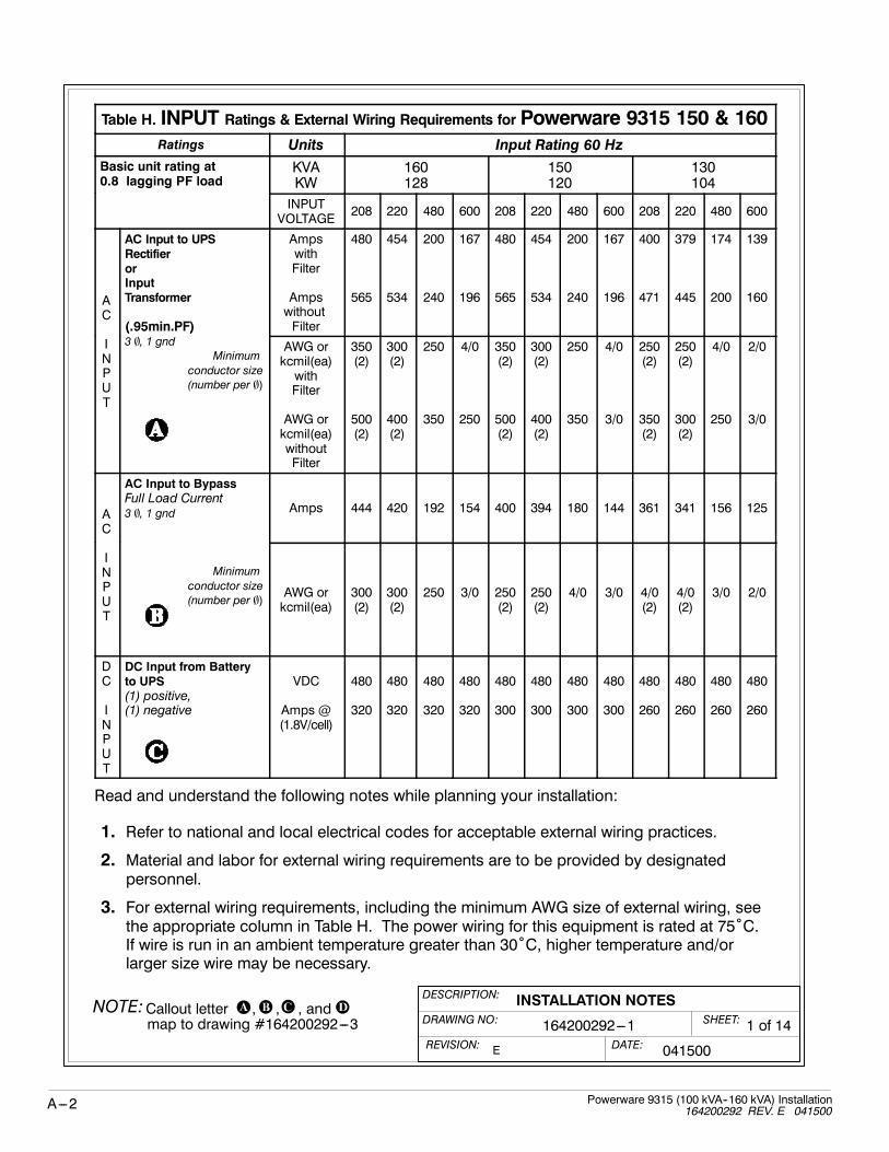
Table H. INPUT Ratings & External Wiring Requirements for Powerware 9315 150 & 160Ratings Units Input Rating 60 Hz
Basic unit rating at0.8 lagging PF load
KVAKW
160128
150120
130104gg g
INPUTVOLTAGE
208 220 480 600 208 220 480 600 208 220 480 600
AC
AC Input to UPSRectifierorInputTransformer
(.95min.PF)
AmpswithFilter
AmpswithoutFilter
480
565
454
534
200
240
167
196
480
565
454
534
200
240
167
196
400
471
379
445
174
200
139
160
INPUT
(.95min.PF)3 , 1 gnd
Minimum
conductor size(number per )
AWG orkcmil(ea)withFilter
AWG orkcmil(ea)withoutFilter
350(2)
500(2)
300(2)
400(2)
250
350
4/0
250
350(2)
500(2)
300(2)
400(2)
250
350
4/0
3/0
250(2)
350(2)
250(2)
300(2)
4/0
250
2/0
3/0
AC
AC Input to BypassFull Load Current3 , 1 gnd Amps 444 420 192 154 400 394 180 144 361 341 156 125
INPUT
Minimum
conductor size(number per ) AWG or
kcmil(ea)300(2)
300(2)
250 3/0 250(2)
250(2)
4/0 3/0 4/0(2)
4/0(2)
3/0 2/0
DC
INPUT
DC Input from Batteryto UPS(1) positive,(1) negative
VDC
Amps @(1.8V/cell)
480
320
480
320
480
320
480
320
480
300
480
300
480
300
480
300
480
260
480
260
480
260
480
260
Read and understand the following notes while planning your installation:
1. Refer to national and local electrical codes for acceptable external wiring practices.
2. Material and labor for external wiring requirements are to be provided by designatedpersonnel.
3. For external wiring requirements, including the minimum AWG size of external wiring, seethe appropriate column in Table H. The power wiring for this equipment is rated at 75˚C.If wire is run in an ambient temperature greater than 30˚C, higher temperature and/orlarger size wire may be necessary.

DESCRIPTION:
DATE:
DRAWING NO: 2 of 14
INSTALLATION NOTESSHEET:
REVISION: E
164200292---1NOTE:Callout letter and
map to drawing #164200292---3, , ,
041500
A---3Powerware 9315 (100 kVA--160 kVA) Installation164200292 Rev. E 041500
Table H. INPUT Ratings & External Wiring Requirements for Powerware 9315150 & 160
Ratings Units Input Rating 60 Hz
Basic unit rating at0.8 lagging PF load
KVAKW
125100
10080gg g
INPUTVOLTAGE
208 220 480 208 600 208 220 480 600
AC
AC Input to UPSRectifierorInputTransformer
(.95min.PF)
AmpswithFilter
AmpswithoutFilter
400
471
379
445
174
200
400
471
139
160
320
377
303
356
139
160
111
131
INPUT
(.95min.PF)3 , 1 gnd
Minimum
conductor size(number per )
AWG orkcmil(ea)withFilter
AWG orkcmil(ea)withoutFilter
250(2)
350(2)
250(2)
300(2)
4/0
250
250(2)
350(2)
2/0
1/0
3/0(2)
250(2)
500
4/0(2)
2/0
3/0
1/0
2/0
AC
I
AC Input to BypassFull Load Current3 , 1 gnd Amps 347 328 150 347 120 278 262 120 96
INPUT
Minimum
conductor size(number per ) AWG or
kcmil(ea)4/0(2)
4/0(2)
3/0 4/0(2)
1/0 500 400 1/0 1/0
DC
INPUT
DC Input from Batteryto UPS(1) positive,(1) negative
VDC
Amps @(1.8V/cell)
480
250
480
250
480
250
480
250
480
250
480
200
480
200
480
200
480
200
Read and understand the following notes while planning your installation:
1. Refer to national and local electrical codes for acceptable external wiring practices.
2. Material and labor for external wiring requirements are to be provided by designatedpersonnel.
3. For external wiring requirements, including the minimum AWG size of external wiring, seethe appropriate column in Table H. The power wiring for this equipment is rated at 75˚C.If wire is run in an ambient temperature greater than 30˚C, higher temperature and/orlarger size wire may be necessary.

DESCRIPTION:
DATE:
DRAWING NO: 3 of 14
INSTALLATION NOTESSHEET:
REVISION: E
164200292---1NOTE:Callout letter and
map to drawing #164200292---3, , ,
041500
A---4 Powerware 9315 (100 kVA--160 kVA) Installation164200292 REV. E 041500
Table I. OUTPUT Ratings & External Wiring Requirements for Powerware 9315 150 & 160Ratings Units Output Rating 60 Hz
Basic unit rating at0.8 lagging PF load
KVAKW
160128
150120
130104gg g
OUTPUTVOLTS
480 208 600 480 208 600 480 208 600
AC
O
AC Output to Critical LoadFull Load Current
3 , (1) Neutral, (1) gnd Amps 192 444 154 180 416 144 156 361 125
OUTPUT
Minimum
conductor size(number per ) AWG or
kcmil(ea)250 300
(2)3/0 4/0 250
(2)3/0 3/0 4/0
(2)2/0
Read and understand the following notes while planning your installation:
1. Refer to national and local electrical codes for acceptable external wiring practices.
2. Material and labor for external wiring requirements are to be provided by designatedpersonnel.
3. For external wiring requirements, including the minimum AWG size of external wiring, seethe appropriate column in Table I. The power wiring for this equipment is rated at 75˚C.If wire is run in an ambient temperature greater than 30˚C, higher temperature and/orlarger size wire may be necessary.

DESCRIPTION:
DATE:
DRAWING NO: 4 of 14
INSTALLATION NOTESSHEET:
REVISION: E
164200292---1NOTE:Callout letter and
map to drawing #164200292---3, , ,
041500
A---5Powerware 9315 (100 kVA--160 kVA) Installation164200292 Rev. E 041500
Table I. OUTPUT Ratings & External Wiring Requirements for Powerware 9315 150 & 160Ratings Units Output Rating 60 Hz
Basic unit rating at0.8 lagging PF load
KVAKW
125100
10080gg g
OUTPUTVOLTS
480 208 600 480 208 600
AC
O
AC Output to Critical LoadFull Load Current
3 , (1) Neutral, (1) gnd Amps 150 347 120 120 278 96
OUTPUT
Minimum
conductor size(number per ) AWG or
kcmil(ea)3/0 4/0
(2)1/0 1/0 500 1/0
Read and understand the following notes while planning your installation:
1. Refer to national and local electrical codes for acceptable external wiring practices.
2. Material and labor for external wiring requirements are to be provided by designatedpersonnel.
3. For external wiring requirements, including the minimum AWG size of external wiring, seethe appropriate column in Table I. The power wiring for this equipment is rated at 75˚C.If wire is run in an ambient temperature greater than 30˚C, higher temperature and/orlarger size wire may be necessary.

DESCRIPTION:
DATE:
DRAWING NO: 5 of 14
INSTALLATION NOTESSHEET:
REVISION: E
164200292---1NOTE:Callout letter and
map to drawing #164200292---3, , ,
400V = 380/400/415 Volt041500
A---6 Powerware 9315 (100 kVA--160 kVA) Installation164200292 REV. E 041500
Table J. Ratings & External Wiring Requirements for Powerware 9315 125, 130, 150,and 160 380/400/415 Volt Units
Ratings Units Rating 50/60 Hz
Basic unit rating at0 8 l i PF l d
Model Plus 160 Plus 150g0.8 lagging PF load
KVAKW
160128
130104
10080
150120
125100
10080
AC Input to UPS RectifierorInputTransformer
( 95 i PF)
Ampswith Input Filter
Ampsw/o input Filter
240
280
200
240
160
198
240
280
200
240
160
198
AC
INPU
(.95min.PF)3 , (1) gnd
Minimumconductor size
(number per )
AWG orkcmil(ea) withInput Filter
AWG orkcmil(ea) withoutInput Filter
350
500
250
350
3/0
250
350
500
250
350
3/0
250
UT AC Input to Bypass
Full Load Current3 , (1) gnd
Amps 231 188 146 217 182 1463 , (1) gnd
Minimum
conductor size(number per )
AWG orkcmil(ea)
350 250 3/0 300 4/0 3/0
DC
IN
DC Input from Batteryto UPS(1) positive, (1) negative
VDC
Amps @(1.8V/cell)
480
320
480
260
480
200
480
300
480
250
480
200
NPUT
Minimum
conductor size
(number per )AWG orkcmil(ea)
400 300 3/0 350 250 3/0
AC
O
AC Output to Critical LoadFull Load Current
3 , (1) Neutral, (1) gndAmps 231 188 146 217 182 146
OUTPUT
Minimum
conductor size
(number per )
AWG orkcmil(ea)
350 250 3/0 300 4/0 3/0
You should read and understand these notes while planning your installation:
1. Refer to national and local electrical codes for acceptable external wiring practices.
2. Material and labor for external wiring requirements are to be provided by designatedpersonnel.
3. For external wiring requirements, including the minimum AWG size of external wiring, seethe appropriate column in Table J. The power wiring for this equipment is rated at 75˚C.If wire is run in an ambient temperature greater than 30˚C, higher temperature and/orlarger size wire may be necessary.

DESCRIPTION:
DATE:
DRAWING NO: 6 of 14
INSTALLATION NOTESSHEET:
REVISION: E
164200292---1NOTE:Callout letter and
map to drawing #164200292---3, , ,
041500400V=380/400/415 Volt
A---7Powerware 9315 (100 kVA--160 kVA) Installation164200292 Rev. E 041500
Table J. Ratings & External Wiring Requirements for Powerware 9315 125, 130, 150,and 160 380/400/415 Volt Units
Ratings Units Rating 50/60 Hz
Basic unit rating at0 8 l i PF l d
Model Plus 130 Plus 125g0.8 lagging PF load
KVAKW
130104
10080
125100
10080
AC Input to UPS RectifierorInputTransformer
( 95 i PF)
Ampswith Input Filter
Ampsw/o input Filter
200
235
160
188
200
235
160
188
AC
INPU
(.95min.PF)3 , (1) gnd
Minimumconductor size
(number per )
AWG orkcmil(ea) withInput Filter
AWG orkcmil(ea) withoutInput Filter
250
350
3/0
250
250
350
3/0
250
UT AC Input to Bypass
Full Load Current3 , (1) gnd
Amps 188 146 182 1463 , (1) gnd
Minimum
conductor size(number per )
AWG orkcmil(ea)
250 3/0 4/0 3/0
DC
IN
DC Input from Batteryto UPS(1) positive, (1) negative
VDC
Amps @(1.8V/cell)
420
297
420
229
420
91
420
69
NPUT
Minimum
conductor size
(number per )AWG orkcmil(ea)
350 4/0 300 4/0
AC
O
AC Output to Critical LoadFull Load Current
3 , (1) Neutral, (1) gndAmps 188 146 182 146
OUTPUT
Minimum
conductor size
(number per )
AWG orkcmil(ea)
250 3/0 4/0 3/0
You should read and understand these notes while planning your installation:
1. Refer to national and local electrical codes for acceptable external wiring practices.
2. Material and labor for external wiring requirements are to be provided by designatedpersonnel.
3. For external wiring requirements, including the minimum AWG size of external wiring, seethe appropriate column in Table J. The power wiring for this equipment is rated at 75˚C.If wire is run in an ambient temperature greater than 30˚C, higher temperature and/orlarger size wire may be necessary.

DESCRIPTION:
DATE:
DRAWING NO: 7 of 14
INSTALLATION NOTESSHEET:
REVISION: C
164200292---1
081596
A---8 Powerware 9315 (100 kVA--160 kVA) Installation164200292 REV. E 041500
1. The output of the UPS is a separately derived source. Output neutral is bonded toequipment ground through the main bonding jumper. Refer to NEC Article 250 and localcodes for proper grounding practices.
2. External overcurrent protection is not provided by this product, but is required by codes.Refer to Tables H through J for wiring requirements. If an output lockable disconnect isrequired, it is to be supplied by designated personnel.
3. When an input transformer is present, the rectifier and bypass inputs may both be suppliedby the same source.
4. Non-linear loads can create neutral currents that are greater than 100%. This product canaccommodate double-sized neutral terminations if needed.
5. Terminals E1 through E15 are UL and CSA rated at 90˚C. A hex key tool is required toattach wires to terminals. Refer to Table K for power cable terminations. Drawing164200292---4 shows the location of the power cable terminals inside the UPS cabinet.
Table K. Power Cable Terminations
Terminal Function Terminal FunctionSize of PressureTermination
TighteningTorque
N---M (lb ---in )Int HexSize (In.)
Internal Wiringto UPS Rectifie
E1 Phase ‘A’ 1 --- #8---350 kcmil 38.1 (275) 5/16to UPS Rectifier
E2 Phase ‘B’ 1 --- #8---350 kcmil 38.1 (275) 5/16
E3 Phase ‘C’ 1 --- #8---350 kcmil 38.1 (275) 5/16
AC Input toUPS I p t
E13 Phase ‘A’ 2 --- #2---600 kcmil 56.5 (500) 1/2UPS InputTransformer
E14 Phase ‘B’ 2 --- #2---600 kcmil 56.5 (500) 1/2Transformer(as applicable) E15 Phase ‘C’ 2 --- #2---600 kcmil 56.5 (500) 1/2
AC Input toB pass
E6 Phase ‘A’ 1 --- #6---350 kcmil 42.4 (375) 3/8Bypass
E7 Phase ‘B’ 1 --- #6---350 kcmil 42.4 (375) 3/8
E8 Phase ‘C’ 1 --- #6---350 kcmil 42.4 (375) 3/8
AC Output toC itical Load
E9 Phase ‘A’ 2 --- #4---500 kcmil 42.4 (375) 3/8Critical Load
E10 Phase ‘B’ 2 --- #4---500 kcmil 42.4 (375) 3/8
E11 Phase ‘C’ 2 --- #4---500 kcmil 42.4 (375) 3/8
E12 Neutral/Gnd. 4 --- #6---350 kcmil 42.4 (375) 3/8
DC Input fromBatte to UPS
E4 Battery (+) 1 --- #4---500 kcmil 42.4 (375) 3/8Battery to UPS
E5 Battery (---) 1 --- #4---500 kcmil 42.4 (375) 3/8
Customer Ground Ground Ground 4 --- #6---350 kcmil 42.4 (375) 3/8

DESCRIPTION:
DATE:
DRAWING NO: 8 of 14
INSTALLATION NOTESSHEET:
REVISION: E
164200292---1
041500
A---9Powerware 9315 (100 kVA--160 kVA) Installation164200292 Rev. E 041500
1. In the UPS system, each battery cabinet, PDM cabinet, and the input transformer cabinetare crated separately for shipping and are bolted together on site.
2. Do not tilt cabinets more than 10˚ during handling.3. Dimensions are in millimeters (inches).4. If perforated floor tiles are required for ventilation, you should place them in front of theUPS. Table L lists the ventilation requirements for full load operation:
Table L. Air Conditioning or Ventilation RequirementsDuring Full Load Operation
Ratings Input/Output VoltageHeat Rejection*
BTU/hr¢ 1000/hr (Kg---cal/hr)
Powerware 9315 125 and 130
100 KVA 400/400 23.8 (5.99)
125 KVA 400/400 29.7 (7.49)
130 KVA 400/400 29.7 (7.49)
Powerware 9315 150 and 160
100 KVA480/208, 480/480 23.8 (5.99)
100 KVA208/208, 600/208, 400/400, 600/600, 220/208 27.0 (6.81)
125 KVA480/208, 480/480 29.7 (7.48)
125 KVA208/208, 600/208, 400/400, 600/600, 220/208 33.8 (8.51)
130 KVA480/208, 480/480 29.7 (7.48)
130 KVA208/208, 600/208, 400/400, 600/600, 220/208 33.8 (8.51)
480/208, 480/480 35.6 (8.98)
150 KVA 208/208, 600/208, 600/600, 220/208 45.5 (11.47)
400/400 40.5 (10.21)
480/208, 480/480 35.6 (8.98)
160 KVA 208/208, 600/208, 600/600, 220/208 45.5 (11.47)
400/400 40.5 (10.21)
*15% higher heat rejection required with optional input transformer.
5. Recommended minimum clearance over the UPS module is 304.8 mm (12 in.).Required for cooling air exhaust: approximately 920 liters/sec (1950 cfm).
6. Battery voltage is computed at 2 volts per cell as defined by Article 480 of the NEC. Ratedbattery current is computed at 1.8 volts per cell.
7. The battery wiring used between the battery and the UPS should not allow a voltage dropof more than 1% of nominal DC voltage at rated battery current.
8. A battery disconnect switch is recommended, and may be required by NEC or local codeswhen batteries are remotely located. The battery disconnect switch may be supplied as anaccessory, and should be installed between battery and UPS.
9. If the conductors used for DC input from the battery cabinet(s) to the UPS are thoseprovided by the UPS manufacturer, and the UPS and battery cabinet are manufactured bythe same supplier, then it is acceptable if they do not meet the noted minimum conductorsizes.

DESCRIPTION:
DATE:
DRAWING NO: 9 of 14
INSTALLATION NOTESSHEET:
REVISION: E
164200292---1
041500
A---10 Powerware 9315 (100 kVA--160 kVA) Installation164200292 REV. E 041500
1. Table M lists the maximum rating for input circuit breakers.
Table M. Maximum Input Circuit Breaker Ratings
Powerware SystemInput Voltage Rating
Powerware System208V 220V 400V 480V 600V
Powerware 9315 160 700 700 400 300 250
Powerware 9315 150 700 700 350 300 250
Powerware 9315 130 N/A N/A 300 N/A N/A
Powerware 9315 125 N/A N/A 300 N/A N/A
2. Source protection for the optional input transformer should be treated as if you weresupplying a three phase transformer, to allow for transformer magnetization inrush current.
3. Source protection for the AC input should be treated as if you were supplying a 200 kVAthree phase transformer, to allow for filter inrush current.
4. Source protection for the input to the bypass section should be treated as if you weresupplying a 200 kVA three phase transformer, to allow for transformer magnetization inrushcurrent.
5. The input breaker (CB1) has a trip rating of 250 amps AT and an amp interruptingcapability (AIC) of 25,000 in symmetrical RMS amps. See Table N:
Table N. Equivalent Transformer Size for Determining Inrush
Standard Input (Auto Transformer) 150 kVA
Optional Input Isolation Transformer 200 kVA
6. The input and bypass three phase feeds should be symmetrical about ground, due to theexistence of voltage surge protection devices.
7. The line-to-line unbalanced output capability of the UPS is limited only by the full load perphase current values for AC output to critical load shown in Tables H through J. Therecommended line-to-line load unbalance is 50% or less.
8. Table O lists the maximum rating for output circuit breakers.
Table O. Maximum Output Circuit Breaker Ratings
Powerware SystemOutput Voltage Rating
Powerware System208V 400V 480V 600V
Powerware 9315 160 600 300 250 200
Powerware 9315 150 600 300 225 200
Powerware 9315 130 N/A 250 N/A N/A
Powerware 9315 125 N/A 225 N/A N/A

DESCRIPTION:
DATE:
DRAWING NO: 10 of 14
INSTALLATION NOTESSHEET:
REVISION: E
164200292---1
041500
A---11Powerware 9315 (100 kVA--160 kVA) Installation164200292 Rev. E 041500
1. Your UPS equipment’s operating environment must meet the size and weight requirementsshown in Table P, according to your UPS system configuration:
2. The basic environmental requirements for operation of the UPS system are:
Ambient Temperature Range: 0---40˚ C (32---104˚ F)
Recommended Operating Range: 20---25˚ C (68---77˚ F)
Maximum Relative Humidity: 95%
Table P. Equipment Weight and Point Loading
Weight Point LoadingComponent Kg (lb) Kg (lb)
UPS Cabinet (Powerware 9315 150 & 160)(480/480 & 480/208 Systems)
1429 (3150) 6 at 238 (525)
UPS Cabinet (Powerware 9315 150 & 160)(208/208, 600/208, 600/600, & 220/208Systems)
2268 (5000) 6 at 378 (833)
UPS Cabinet (Powerware 9315 150 & 160)(400/400 Systems)
1803 (3975) 6 at 301 (663)
UPS Cabinet (Powerware 9315 125 & 130)(400/400 Systems)
1429 (3150) 6 at 238 (525)
Transformer Cabinet (maximum) 636 (1400) 4 at 160 (350)
PDM Cabinet 226 (500) 4 at 57 (125)
Battery Cabinets:
Series 685---J14 869 (1915) 4 at 217 (479)
Series 685---J17 1111 (2450) 4 at 278 (613)
Series 1085---J27 1429 (3150) 8 at 179 (394)
Series 1085---J31 1588 (3500) 8 at 199 (438)
Series 1085---J37 1708 (3765) 8 at 214 (471)
Series 1085---J47 2178 (4800) 8 at 272 (600)

DESCRIPTION:
DATE:
DRAWING NO:
INSTALLATION NOTESSHEET:
REVISION: C
164200292---1 11 of 14
081596
TB1
BLDG ALARM 1
BLDG ALARM 4
BLDG ALARM 5
1
2
3
4
5
6
7
8
9
15
10
11
14
13
12
TB2
BLDG ALARM 2
BLDG ALARM 3
BLDG ALARM 6
1
2
3
4
5
6
7
8
9
15
10
11
14
13
12
RS232
RS485
ON BYPASS
BATTERY CONTACTOR CLOSED
RELAY 2 NC
ON INV
RELAY 2 NO
RELAY 1 NC
RELAY 1 NO
BLDG ALARM 1 RTN
BLDG ALARM 4 RTN
BLDG ALARM 5 RTN
BLDG ALARM 2 RTN
BLDG ALARM 3 RTN
BLDG ALARM 6 RTN
REMOTE EPO
REMOTE EPO RTN
ON BYPASS RTN
BATTERY CONT RTN
ON INV RTN
NOTICE RTN
ALARM RTN
Communications Panel
A---12 Powerware 9315 (100 kVA--160 kVA) Installation164200292 REV. E 041500
NOTE: All building alarm inputs or remote features require an isolated normally open contact or switch(rated at 24 VDC, 20mA minimum) connected between the alarm input and common terminal asshown. All control wiring and relay and switch contacts are customer provided.
NOTE: Regardless of assignment, alarms display as Building Alarm 1, Building Alarm 2, etc., on MonitorPanel. Use twisted pair wires for each alarm input and common.

DESCRIPTION:
DATE:
DRAWING NO:
INSTALLATION NOTESSHEET:
REVISION: C
164200292---1 12 of 14
081596
A---13Powerware 9315 (100 kVA--160 kVA) Installation164200292 Rev. E 041500
Table Q. Communications Panel Inputs and Outputs
TB1 Pin # Name Description
1 BLDG ALARM 1 Programmable UPS alarm. Activated by a remote
2 BLDG ALARM 1 RTN
Programmable UPS alarm. Activated by a remotecontact closure.
3 BLDG ALARM 2 Programmable UPS alarm. Activated by a remote
4 BLDG ALARM 2 RTN
Programmable UPS alarm. Activated by a remotecontact closure.
5 BLDG ALARM 3 Programmable UPS alarm. Activated by a remote
6 BLDG ALARM 3 RTN
Programmable UPS alarm. Activated by a remotecontact closure.
7 BLDG ALARM 4 Programmable UPS alarm. Activated by a remote
8 BLDG ALARM 4 RTN
Programmable UPS alarm. Activated by a remotecontact closure.
9 BLDG ALARM 5 Programmable UPS alarm. Activated by a remote
10 BLDG ALARM 5 RTN
Programmable UPS alarm. Activated by a remotecontact closure.
11 BLDG ALARM 6 Programmable UPS alarm. Activated by a remote
12 BLDG ALARM 6 RTN
Programmable UPS alarm. Activated by a remotecontact closure.
Table R. Communications Panel Inputs and Outputs
TB2 Pin # Name Description
1 REMOTE EPOContacts used to activate remote EPO of UPS
2 REMOTE EPO RTNContacts used to activate remote EPO of UPS.
3
4 ON INVContacts used to indicate On Inverter status of UPS
5 ON INV RTNContacts used to indicate On Inverter status of UPS.
6 ON BYPASSContacts used to indicate On Bypass status of UPS
7 ON BYPASS RTNContacts used to indicate On Bypass status of UPS.
8BATTERY CONTACTORCLOSED Contacts used to indicate UPS Battery Contactor is
l d9 BATTERY CONT RTN
closed.
10 RELAY 1 NC
11 RELAY 1 NO General purpose NO and NC relay contacts.
12 ALARM RTN
p p y
13 RELAY 2 NC
14 RELAY 2 NO General purpose NO and NC relay contacts.
15 NOTICE RTN
p p y

DESCRIPTION:
DATE:
DRAWING NO: 13 of 14
INSTALLATION NOTESSHEET:
REVISION: C
164200292---1
081596
A---14 Powerware 9315 (100 kVA--160 kVA) Installation164200292 REV. E 041500
1. Use Class 1 wiring methods (as defined by the NEC), for control wiring. Install the controlwiring in separate conduit from the power wiring. The wire should be rated at 24 volts, 1amp minimum.
2. Refer to Tables S, T, and U, and to applicable chapters for information about installingcontrol wiring for options and accessories.
Table S. Control Wiring Terminationsg
Terminal Description Terminal Function
TB1 Terminal Block Building Alarms (optional, up to 6)
Generator Interface
TB1 Terminal Block Remote EPO
TB2
TB2“On Inverter” Monitoring
TB2“On Bypass” Monitoring
Summary Alarm & Notice Contacts
Table T. Summary Alarm Relay Contacts
CONTACT RATING:
Maximum Switched Voltage 32 VAC 42 VDC
Maximum Carrying Current 1A
14
15
13
11
12
10
RELAY 1
TB2
RELAY 2

DESCRIPTION:
DATE:
DRAWING NO:
INSTALLATION NOTESSHEET:
REVISION: B
164200292---1 14 of 14
081596
A---15Powerware 9315 (100 kVA--160 kVA) Installation164200292 Rev. E 041500
3. The Remote EPO feature opens all breakers and contactors in the UPS cabinet andisolates power from your critical load. Local electrical codes may also require trippingupstream protective devices to the UPS.
Table U. Remote EPO
Remote EPO switch rating is 24 VDC.1 amp minimum if supplied by user.
NOTE: This switch must be a dedicated switch, and nottied into any other circuits.
1
2
REMOTEEPOSWITCH
TWISTEDWIRES (2)
TB2

A---16 Powerware 9315 (100 kVA--160 kVA) Installation164200292 REV. E 041500
(optional)
PDM CABINET(optional)
INPUTTRANSFORMERCABINET
CABINETUPS
CABINETBATTERY
(optional)(up to four)
DESCRIPTION:
DATE:
DRAWING NO:
TYPICAL UPS SYSTEMSHEET:
REVISION: B
164200292---2 1 of 1
010496

A---17Powerware 9315 (100 kVA--160 kVA) Installation164200292 Rev. E 041500
DESCRIPTION:
DATE:
DRAWING NO: SHEET:
REVISION: C
PANELBOARD
PANELBOARD
PDM CABINET(OPTIONAL) UPS CABINET
BATTERY
TRANSFORMER
CRITICALLOAD
CABINET(OPTIONAL)
E13---15
F61
INVERTER
RECTIFIER
INPUT FILTER
CB1
BATTERYCONTACTOR
MAINBONDINGJUMPER
TO GROUND
ACOUTPUT
TO
E4---5
OUTPUTCONTACTOR
TOADDITIONALBATTERYCABINET(OPTIONAL)
STATIC
SWITCH
OUTPUT FILTER
(K3)
BYPASSCONTACTOR
(K4)
(K2)
F62F63
E9---12
NUMBER 2
NUMBER 1
“ON INVERTER”“ON BYPASS”MONITORING
RS---232
RS---485
REMOTE EPO
GENERATORINTERFACE
AC INPUT TOUPS RECTIFIER AND BYPASS3 WIRE, A---B---C ROTATION
BUILDING ALARMS(See Tables Q, R, S, T, and U)
164200292---3
ONELINE DRAWINGS OF UPS SYSTEM
UPS SYSTEM WITH 208V INPUT
E1---3
COMMUNICATIONSPANEL
INPUT
(OPTIONAL)
TRANSFORMERCABINET
E6, 7, 8
1 of 7
081596
OUTPUTTRANSFORMER(SEE NOTE 1)
Y
Y
n
NOTE 1: There is a zero degree phase shiftthrough the bypass windings of theoutput transformer.

A---18 Powerware 9315 (100 kVA--160 kVA) Installation164200292 REV. E 041500
PANELBOARD
PANELBOARD
PDM CABINET(OPTIONAL) UPS CABINET
BATTERY
TRANSFORMER
CRITICALLOAD
CABINET(OPTIONAL)
E13---15
F61
INVERTER
RECTIFIER
INPUT FILTER
CB1
BATTERYCONTACTOR
MAINBONDINGJUMPER
TO GROUND
ACOUTPUT
TO
E4---5
OUTPUTCONTACTOR
TOADDITIONALBATTERYCABINET(OPTIONAL)
STATIC
SWITCH
OUTPUT FILTER
(K3)
BYPASSCONTACTOR
(K4)
(K2)
F62F63
E9---12
NUMBER 2
NUMBER 1
“ON INVERTER”“ON BYPASS”MONITORING
RS---232
RS---485
REMOTE EPO
GENERATORINTERFACE
AC INPUT TOUPS RECTIFIER AND BYPASS3 WIRE, A---B---C ROTATION
BUILDING ALARMS
UPS SYSTEM WITH 600V INPUT
E1---3
COMMUNICATIONSPANEL
E6, 7, 8
DESCRIPTION:
DATE:
DRAWING NO: SHEET:
REVISION: C
164200292---3
ONELINE DRAWINGS OF UPS SYSTEM
2 of 7
081596
OUTPUTTRANSFORMER(SEE NOTE 1)
Y
Y
n
NOTE 1: There is a zero degree phase shiftthrough the bypass windings of theoutput transformer.
(See Tables Q, R, S, T, and U)

A---19Powerware 9315 (100 kVA--160 kVA) Installation164200292 Rev. E 041500
PANELBOARD
PANELBOARD
PDM CABINET(OPTIONAL)
INPUT
CABINET(OPTIONAL) UPS CABINET
BATTERY
TRANSFORMER
CABINET(OPTIONAL)
E13---15
F61
INVERTER
RECTIFIER
INPUT FILTER
CB1
BATTERYCONTACTOR
MAINBONDINGJUMPER
TO GROUND
E4---5
OUTPUTCONTACTOR
TOADDITIONALBATTERYCABINET(OPTIONAL)
STATIC
SWITCH
OUTPUT FILTER
(K3)
BYPASSCONTACTOR
(K4)
(K2)
F62F63
E9---12
NUMBER 2
NUMBER 1
“ON INVERTER”“ON BYPASS”MONITORING
RS---232
RS---485
REMOTE EPO
GENERATORINTERFACE
AC INPUT TOUPS RECTIFIER
3 WIRE, A---B---C ROTATION
BUILDING ALARMS
UPS SYSTEM WITH DUAL INPUTS
SEE NOTE 1
COMMUNICATIONSPANEL
(208V INPUT)
E6, 7, 8
TRANSFORMERINPUT
CABINET(OPTIONAL)
TRANSFORMER
E13---15
AC INPUT TOUPS BYPASS
3 WIRE, A---B---C ROTATION
TRANSFORMER
DESCRIPTION:
DATE:
DRAWING NO: SHEET:
REVISION: C
164200292---3
ONELINE DRAWINGS OF UPS SYSTEM
3 of 7
081596
CRITICAL
LOAD
AC
OUTPUT
TO
OUTPUTTRANSFORMER(SEE NOTE 2)
Y
Y
n
NOTE 2: There is a zero degree phase shiftthrough the bypass windings of theoutput transformer.
NOTE 1: Remove power jumpers betweenCB1 and F61, F62, and F63 if present.
(See Tables Q, R, S, T, and U)

A---20 Powerware 9315 (100 kVA--160 kVA) Installation164200292 REV. E 041500
PANELBOARD
PANELBOARD
PDM CABINET(OPTIONAL)
INPUT
CABINET(OPTIONAL) UPS CABINET
BATTERY
TRANSFORMER
CRITICALLOAD
CABINET(OPTIONAL)
E13---15
F61
INVERTER
RECTIFIER
INPUT FILTER
CB1
BATTERYCONTACTOR
MAINBONDINGJUMPER
TO GROUND
ACOUTPUT
TO
E4---5
OUTPUTCONTACTOR
TOADDITIONALBATTERYCABINET(OPTIONAL)
STATIC
SWITCH
OUTPUT FILTER
(K3)
BYPASSCONTACTOR
(K4)
(K2)
F62F63
E9---12
NUMBER 2
NUMBER 1
“ON INVERTER”“ON BYPASS”MONITORING
RS---232
RS---485
REMOTE EPO
GENERATORINTERFACE
AC INPUT TOUPS RECTIFIER
3 WIRE, A---B---C ROTATION
BUILDING ALARMS
UPS SYSTEM WITH DUAL FEED OR OPTIONAL INPUT ISOLATION TRANSFORMER
(600V INPUT)
E13---15
E1---3
SEE NOTE 1
AC INPUTTO BYPASS3 WIRE A---B---CROTATION
AUTOTRANSFORMER
COMMUNICATIONSPANEL
E6, 7, 8
DESCRIPTION:
DATE:
DRAWING NO: SHEET:
REVISION: C
164200292---3
ONELINE DRAWINGS OF UPS SYSTEM
4 of 7
081596
OUTPUTTRANSFORMER(SEE NOTE 2)
Y
Y
n
NOTE 2: There is a zero degree phase shiftthrough the bypass windings of theoutput transformer.
NOTE 1: Remove power jumpers betweenCB1 and F61, F62, and F63 if present.
(See Tables Q, R, S, T, and U)

A---21Powerware 9315 (100 kVA--160 kVA) Installation164200292 Rev. E 041500
PANELBOARD
PANELBOARD
PDM CABINET(OPTIONAL) UPS CABINET
BATTERY
CRITICALLOAD
CABINET(OPTIONAL)
E6---8E1---3
F61
INVERTER
RECTIFIER
INPUT FILTER
CB1
BATTERYCONTACTOR
MAINBONDINGJUMPER
TO GROUND
ACOUTPUT
TO
E4---5
OUTPUTCONTACTOR
TOADDITIONALBATTERYCABINET(OPTIONAL)
STATIC
SWITCH
OUTPUT FILTER
(K3)
BYPASSCONTACTOR
(K4)
(K2)
F62F63
E9---12
NUMBER 2
NUMBER 1
“ON INVERTER”“ON BYPASS”MONITORING
RS---232
RS---485
REMOTE EPO
GENERATORINTERFACE
AC INPUT TOUPS RECTIFIER3 WIRE, A---B---C
BUILDING ALARMS
UPS SYSTEM WITH 480V INPUT, SINGLE OR DUAL FEED
AC INPUT TOBYPASS
3 WIRE, A---B---CROTATION ROTATION
SEE NOTE 1
COMMUNICATIONSPANEL
DESCRIPTION:
DATE:
DRAWING NO: SHEET:
REVISION: C
164200292---3
ONELINE DRAWINGS OF UPS SYSTEM
5 of 7
081596
OUTPUTTRANSFORMER(SEE NOTE 2)
Y
Y
n
NOTE 2: There is a zero degree phase shiftthrough the bypass windings of theoutput transformer.
NOTE 1: Optional jumper for single feed. Useterminals E6, E7, and E8 for connection.See Table J, row for wire rating.
(See Tables Q, R, S, T, and U)

A---22 Powerware 9315 (100 kVA--160 kVA) Installation164200292 REV. E 041500
PANELBOARD
PANELBOARD
PDM CABINET(OPTIONAL)
INPUT
CABINET(OPTIONAL) UPS CABINET
BATTERY
ISOLATIONTRANSFORMER
CRITICALLOAD
CABINET(OPTIONAL)
E13---15
F61
INVERTER
RECTIFIER
INPUT FILTER
CB1
BATTERYCONTACTOR
MAINBONDINGJUMPER
TO GROUND
ACOUTPUT
TO
E4---5
OUTPUTCONTACTOR
TOADDITIONALBATTERYCABINET(OPTIONAL)
STATIC
SWITCH
OUTPUT FILTER
(K3)
BYPASSCONTACTOR
(K4)
(K2)
F62F63
E9---12
NUMBER 2
NUMBER 1
“ON INVERTER”“ON BYPASS”MONITORING
RS---232
RS---485
REMOTE EPO
GENERATORINTERFACE
AC INPUT TOUPS RECTIFIER
3 WIRE, A---B---C ROTATION
BUILDING ALARMS
UPS SYSTEM WITH OPTIONAL INPUT ISOLATION TRANSFORMER
(480V INPUT)
E6---8
E1---3
AC INPUTTO BYPASS3 WIRE A---B---CROTATION
COMMUNICATIONSPANEL
DESCRIPTION:
DATE:
DRAWING NO: SHEET:
REVISION: C
164200292---3
ONELINE DRAWINGS OF UPS SYSTEM
6 of 7
081596
OUTPUTTRANSFORMER(SEE NOTE 1)
Y
Y
n
NOTE 1: There is a zero degree phase shiftthrough the bypass windings of theoutput transformer.
(See Tables Q, R, S, T, and U)

A---23Powerware 9315 (100 kVA--160 kVA) Installation164200292 Rev. E 041500
PANELBOARD
PANELBOARD
PDM CABINET(OPTIONAL) UPS CABINET
BATTERY
CRITICALLOAD
CABINET(OPTIONAL)
E13---15
F61
INVERTER
RECTIFIER
INPUT FILTER
CB1
BATTERYCONTACTOR
MAINBONDINGJUMPER
TO GROUND
ACOUTPUT
TO
E4---5
OUTPUTCONTACTOR
TOADDITIONALBATTERYCABINET(OPTIONAL)
STATIC
SWITCH
OUTPUT FILTER
(K3)
BYPASSCONTACTOR
(K4)
(K2)
F62F63
E9---12
NUMBER 2
NUMBER 1
“ON INVERTER”“ON BYPASS”MONITORING
RS---232
RS---485
REMOTE EPO
GENERATORINTERFACE
AC INPUT TOUPS RECTIFIER
3 WIRE, A---B---C ROTATION
BUILDING ALARMS
UPS SYSTEM WITH 400V INPUT, SINGLE OR DUAL FEED
E1---3
E6---8
AC INPUT
SEE NOTE 1
TO BYPASS3 WIRE A---B---CROTATION
COMMUNICATIONSPANEL
DESCRIPTION:
DATE:
DRAWING NO: SHEET:
REVISION: C
164200292---3
ONELINE DRAWINGS OF UPS SYSTEM
7 of 7
081596
OUTPUTTRANSFORMER(SEE NOTE 1)
Y
Y
n
NOTE 2: There is a zero degree phase shiftthrough the bypass windings of theoutput transformer.
NOTE 1: Optional jumper for single feed. Useterminals E6, E7, and E8 for connection.See Table L, row for wire rating.
(See Tables Q, R, S, T, and U)

A---24 Powerware 9315 (100 kVA--160 kVA) Installation164200292 REV. E 041500
TB1 TB2
DC INPUTfrom battery
to UPS(E4, E5)
CB1AC INPUT TOUPS RECTIFIER(E1, E2, E3)(A, B, C)
UPS INPUT(E13, E14, E15)(A, B, C)(If needed)
AC INPUTTO BYPASS(E6, E7, E8)(A, B, C)
INPUTGROUND
OUTPUTNEUTRAL
CONNECTION(E12)
PORT 1 (DE---9)RS---232/485connection
(J3)
BATTERY BREAKERSENSING CABLE
COMMUNICATIONPANEL
PORT 2 (DB---25)RS---232CONNECTION
BATTERYCABLE
MAINBONDINGJUMPER
DESCRIPTION:
DATE:
DRAWING NO: SHEET:
REVISION: A
164200292---4
LOCATION OF UPS POWER TERMINALS
1 of 1
060995
AC OUTPUT(E9, E10, E11)

A---25Powerware 9315 (100 kVA--160 kVA) Installation164200292 Rev. E 041500
25(1.0)
1870(73.6)
Dimensions are in millimeters (inches)
1258(49.3)
1209(47.4)
399 (typ)(15.7)
DESCRIPTION:
DATE:
DRAWING NO: SHEET:
REVISION: A
164200292---5
UPS CABINET
1 of 2
060995

A---26 Powerware 9315 (100 kVA--160 kVA) Installation164200292 REV. E 041500
Dimensions are in millimeters (inches)
DESCRIPTION:
DATE:
DRAWING NO: SHEET:
REVISION: A
164200292---5
UPS CABINET
2 of 2
060995
TOP
BOTTOM
50
911
90
98
30 (typ)
48580
410
390146
1209
8.9 (3.50)SWIVEL RADIUS
(TYPICAL)
951.7
110.8
762
266
VIEW
VIEW
UPS CABINET
UPS CABINET
TOPWIREENTRY
BOTTOMWIRE
COOLINGAIR EXHAUST
ENTRY
(1.18)(4.36)
(37.47)
(16.14)
(1.89)(22.83)
(10.47)
(30.0)
612
(1.97)
(15.34)
(35.9)
(47.6)
(3.86)
(24.1)
(3.54)
(5.75)
FRONT
1258(49.5)
340(13.4)
914.4 (36.00)MINIMUM CLEARANCEFOR SUBASSEMBLY
REMOVAL
800(31.5)
FRONT
476(18.74)
240(9.4)

A---27Powerware 9315 (100 kVA--160 kVA) Installation164200292 Rev. E 041500
DOOR SWING624.8 (24.60)X 90 DEGREES
122.7(4.83)
88.9 (3.5)SWIVEL RADIUS
142.4(5.61)
609.6(24.00)
635.5(25.02)
375.7(14.79)
CABINETTOP CABLE ENTRY
LOCATION
27.2(1.07)
AIR VENTINGCOVER
209.5(8.25)
409.6(16.13)
183.2(7.21)
TOP VIEW
BOTTOM VIEW
FRONT
FRONT
25.4(1.00)
914.4 (36.00)MINIMUM CLEARANCE
FOR SUBASSEMBLYREMOVAL
1870(73.6)
Dimensions are in millimeters (inches)
DESCRIPTION:
DATE:
DRAWING NO: SHEET:
REVISION: A
164200292---6
INPUT TRANSFORMER CABINET
1 of 1
060995

A---28 Powerware 9315 (100 kVA--160 kVA) Installation164200292 REV. E 041500
DESCRIPTION:
DATE:
DRAWING NO: SHEET:
REVISION: E
164200292---7 1 of 1
041500
42-Pole PanelboardWith Main Breaker225A 600V Square D TypeNQOM442M225IG--NL
Branches--QO Plug-Onand QOB Bolt-On CircuitBreaker. 15--70A, 1-Pole;15--100A 2- and 3-Pole;125A, 2-Pole.
GroundingStud
GroundingStud
�A E1
�B E2
�C E3
Neutral E4
PB2(Optional)
Input Ground(2) #6--350 KCM
NOTE 1: Refer to Powerware 9315 PowerDistribution Module Installation andOperationManual 164201061 forPDM installation and operation.
POWER DISTRIBUTION MODULE

A---29Powerware 9315 (100 kVA--160 kVA) Installation164200292 Rev. E 041500
DESCRIPTION:
DATE:
DRAWING NO: SHEET:
REVISION: E
164200292---8 1 of 1
041500
MBP
MIS
BIB1
BIB2
BREAKER ANNUNCIATION
CRITICAL LOADCONNECTIONS
NEUTRALCONNECTIONS
OPTIONAL UPSBYPASSINPUT CONNECTIONS
UTILITY INPUT,IF BIB BREAKERINSTALLED
UPS/PTC OUTPUTCONNECTION
UTILITY INPUT,IF BIB BREAKERIS NOTINSTALLED
MAINTENANCE BYPASS MODULE
NOTE 1: Refer to Powerware 9315 Maintenance BypassModule (MBM) Installation and Operation Manual164201177 for MBM installation and operation.

A---30 Powerware 9315 (100 kVA--160 kVA) Installation164200292 REV. E 041500
114.3(4.50)
115.8(4.56)
11.9(0.47)
95.3(3.75)SQUARE
88.9(3.50)
Knockout patterntyp. 5 sides
TO UPS TO OTHEREQUIPMENT
Dimensions are in millimeters (inches)
DESCRIPTION:
DATE:
DRAWING NO: SHEET:
REVISION: E
164200292---9
REMOTE EMERGENCY POWER OFF
1 of 1
041500

A---31Powerware 9315 (100 kVA--160 kVA) Installation164200292 Rev. E 041500
MAX. WIRE SIZE: NO. 14 AWGMIN. WIRE SIZE: NO. 18 AWG
WIRES MUSTCONDUIT AND WIRING SUPPLIED BYCUSTOMER. MAX. DISTANCE BETWEENREMOTE MONITOR AND UPS NOT TO
EXCEED 500 FEET.
41.1(1.62)
25.4(1.00)
190.5(7.50)
88.9(3.50)
.750
215.9(8.50)
100.1(3.94)
74.7(2.94)
171.5(6.75)
KNOCKOUTS PROVIDEDON FIVE SURFACES
BE TWISTED
FLUSH MOUNT
SURFACE
(FOR HANGING)
(14---18 gauge)
Dimensions are in millimeters (inches)
MOUNT
DESCRIPTION:
DATE:
DRAWING NO: SHEET:
REVISION: E
164200292---10
REMOTE MONITOR PANEL
1 of 1
041500
285.7(11.25)

A---32 Powerware 9315 (100 kVA--160 kVA) Installation164200292 REV. E 041500
19.0(.750)
28.6(1.12)
41.1(1.62)
EXISTINGINTERNAL
FLUSH MOUNT
SURFACEMOUNT
CONTINUES AT UPS
MAX WIRE SIZE NO. 14 AWG.MIN WIRE SIZE NO. 18 AWG.
Relay Interface Module
88.9(3.50)
190.5(7.50)
215.9(8.5)
196.8(7.75)
FOR HANGING
WIRING CONDUIT ANDWIRING SUPPLIEDBY CUSTOMER.
Maximum distance betweenRIM and UPS not to exceed
500 feet. Wires must be twisted.
Dimensions are in millimeters (inches)
DESCRIPTION:
DATE:
DRAWING NO: SHEET:
REVISION: E
164200292---11
RELAY INTERFACE MODULE
1 of 2
041500

A---33Powerware 9315 (100 kVA--160 kVA) Installation164200292 Rev. E 041500
15---PIN D---SUBCONNECTORS
25.4(1.00)
KNOCKOUTS PROVIDEDON FIVE SURFACES
285.7(11.25)
273.1(10.75)
215.9(8.50)
171.5(6.75)
74.6(2.94)
100.0(3.94)
Dimensions are in millimeters (inches)
DESCRIPTION:
DATE:
DRAWING NO: SHEET:
REVISION: E
164200292---11
RELAY INTERFACE MODULE
2 of 2
041500

A---34 Powerware 9315 (100 kVA--160 kVA) Installation164200292 REV. E 041500
MAX. WIRE SIZE: NO. 14 AWGMIN. WIRE SIZE: NO. 18 AWG
WIRES MUSTCONDUIT AND WIRING SUPPLIED BYCUSTOMER. MAX. DISTANCE BETWEENREMOTE MONITOR AND UPS NOT TO
EXCEED 500 FEET.
41.1(1.62)
25.4(1.00)
190.5(7.50)
88.9(3.50)
.750
215.9(8.50)
100.1(3.94)
74.7(2.94)
171.5(6.75)
KNOCKOUTS PROVIDEDON FIVE SURFACES
BE TWISTED
FLUSH MOUNT
SURFACE
(FOR HANGING)
Dimensions are in millimeters (inches)
MOUNT
DESCRIPTION:
DATE:
DRAWING NO: SHEET:
REVISION: E
164200292---12
SUPERVISORY CONTACT MODULE
1 of 1
041500
285.7(11.25)