power mode bypass controller to suit komatsu hd785 …
TRANSCRIPT

PRODUCT MANUAL POWER MODE BYPASS CONTROLLER TO SUIT KOMATSU HD785-5 AND HD785-7 VEHICLES
Part No. 11337 | 12731
2 | 16 M0698.docx | Rev 2.4 | Modified on 26/03/2021 | © Remote Control Technologies Pty Ltd
LEGAL NOTICE
1. You acknowledge that this document is protected under copyright law and Remote Control Technologies Pty Ltd or its related bodies corporate (“RCT”) owns the copyright in this document or otherwise have permission or licence from the relevant owner to use certain specific works.
2. You must not make any changes, amendments, variations, alterations or modifications to the document.
3. You must not reproduce this document in any form or by any means, or to make copies of this document without RCT’s prior written consent.
4. The contents in this document constitute confidential information of RCT. You must not circulate, distribute or otherwise allow the document to be available in the public domain, or to disclose or share the document with any third party, without RCT’s prior written consent.
5. RCT provides the document to you on an “as is” basis. RCT is not required to provide any updates to this version of the document. RCT may make any change, amendment or modification to the contents in this document without notice to you.
6. RCT takes a best endeavour basis to ensure that the contents in this document are accurate, complete and reliable. RCT does not warrant that the document will continue to be reliable, relevant, accurate or complete due to RCT’s continuous efforts in product development, innovation and technology.
7. Any trademarks used in this document belongs to RCT or is used under a licence. The trademarks are not to be used for any purposes, without RCT’s prior written consent.
8. Any illustrations used in this document are for illustration purposes only. Illustrations are intended as aids to facilitate your understanding of the subject matter or issue.
9. RCT disclaims all liability, loss or damage that you suffer as a result of your reliance on this document.
10. By your conduct of using or reading this document, you agree to and accept the terms in this notice.
M0698.docx | Rev 2.4 | Modified on 26/03/2021 | © Remote Control Technologies Pty Ltd 3 | 16
Contents
GENERAL SAFETY WARNINGS 4
PRODUCT OVERVIEW 5
FEATURES AND FUNCTIONS 5
OPERATION AND USE 5
CONTROLLER STATUS INDICATOR OPERATION 6
INSTALLATION GUIDE 7
INSTALLATION FOR KOMATSU HD785-5 7
- WIRING CONNECTIONS 7 INSTALLATION FOR KOMATSU HD785-7 8
- WIRING CONNECTIONS 8 DIAGRAMS 9
- WIRING DIAGRAM TO SUIT KOMATSU HD785-5 (519c) 9 - WIRING DIAGRAM TO SUIT KOMATSU HD785-7 (519d) 10 - WIRING DIAGRAM TO SUIT KOMATSU HD465 AND HD605 (590a) 11
CALIBRATION 12
SERVICE INFORMATION 12
SERVICE SCHEDULE 12 SERVICE PROCEDURE 12
PARTS LIST 13
TECHNICAL SPECIFICATIONS 13
COMPLIANCE AND STANDARDS 14
TROUBLESHOOTING 14
GLOSSARY 15
WARRANTY 15

4 | 16 M0698.docx | Rev 2.4 | Modified on 26/03/2021 | © Remote Control Technologies Pty Ltd
GENERAL SAFETY WARNINGS
PERSONAL SAFETY
■ Everyone is responsible for safety.
■ The installer/service personnel should be trained and authorized to complete the required work.
■ Ensure that the machine is safely isolated during installation and testing to protect all personnel.
■ Complete all required risk assessments and job safety analysis (JSA) before commencing work.
■ Observe all site specific and machine OEM procedures regarding the following:
– working at heights
– working in heat
– working in confined spaces
– all other site specific occupational health and safety (OH&S) procedures
MACHINE ■ Carry out all prestart operations as per site and machine OEM procedures.
■ Ensure the machine is safely isolated during installation and testing to protect the machine and other equipment in the area.
■ Do not operate any machine with a known fault and report all findings to the supervisor in writing.
■ Test and operate machine as per machine OEM and site procedures.
■ Read and understand machine and site specific operational and testing instructions.
PRODUCT Before applying power to the equipment, the user/repairer/ installer must read all product instructions. If in doubt, seek assistance. ■ Ensure electrical connections are made as per RCT’s recommendations. Test circuits prior to connecting
power to any component.
■ The equipment contains no user serviceable parts inside. Return the unit to RCT for repairs.
■ Retain product and installation instructions for future use.
■ Ensure that RCT’s recommended service procedures are included in the machine’s service routine.
■ Observe all machine, site and RCT product warnings.
■ Follow all machine, site and RCT product operating procedures at all time.
The application of safety should not be limited to the above recommendations.

M0698.docx | Rev 2.4 | Modified on 26/03/2021 | © Remote Control Technologies Pty Ltd 5 | 16
PRODUCT OVERVIEW
The Muirhead® Power Mode Bypass Controller, part number 11337, is designed to automatically select either standard mode or power mode based on whether or not the tray is loaded.
FEATURES AND FUNCTIONS ■ Multi-voltage 12-24 V
■ Environmentally sealed – IP65
■ Simple to install ■ No ongoing maintenance ■ Power boost switch available as an option
OPERATION AND USE When no load is detected, the Muirhead® Power Mode Bypass Controller will automatically select standard mode. When a heavy load is detected, the controller will automatically select power mode. The controller automatically filters the payload input to eliminate the controller falsely changing states. An optional momentary switch or key-switch can be fitted to manually place the vehicle into power mode. This may be used for servicing of the vehicle or where a boost of power from the vehicle is required. By default, the override switch will turn power mode on for 30 seconds
6 | 16 M0698.docx | Rev 2.4 | Modified on 26/03/2021 | © Remote Control Technologies Pty Ltd
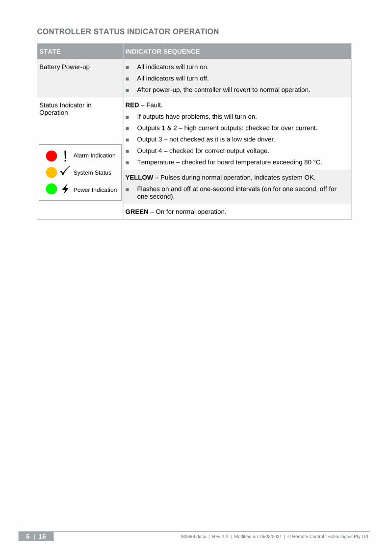
CONTROLLER STATUS INDICATOR OPERATION
STATE INDICATOR SEQUENCE
Battery Power-up ■ All indicators will turn on.
■ All indicators will turn off.
■ After power-up, the controller will revert to normal operation.
Status Indicator in Operation
RED – Fault.
■ If outputs have problems, this will turn on.
■ Outputs 1 & 2 – high current outputs: checked for over current.
■ Output 3 – not checked as it is a low side driver.
■ Output 4 – checked for correct output voltage.
■ Temperature – checked for board temperature exceeding 80 °C.
YELLOW – Pulses during normal operation, indicates system OK.
■ Flashes on and off at one-second intervals (on for one second, off for one second).
GREEN – On for normal operation.
Alarm Indication
System Status
Power Indication
M0698.docx | Rev 2.4 | Modified on 26/03/2021 | © Remote Control Technologies Pty Ltd 7 | 16
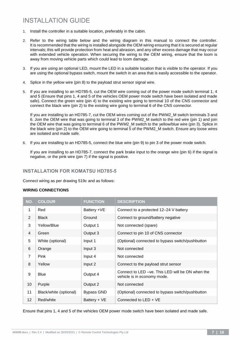
INSTALLATION GUIDE 1. Install the controller in a suitable location, preferably in the cabin.
2. Refer to the wiring table below and the wiring diagram in this manual to connect the controller.
It is recommended that the wiring is installed alongside the OEM wiring ensuring that it is secured at regular intervals; this will provide protection from heat and abrasion, and any other excess damage that may occur with extended vehicle operation. When securing the wiring to the OEM wiring, ensure that the loom is away from moving vehicle parts which could lead to loom damage.
3. If you are using an optional LED, mount the LED in a suitable location that is visible to the operator. If you
are using the optional bypass switch, mount the switch in an area that is easily accessible to the operator. 4. Splice in the yellow wire (pin 8) to the payload strut sensor signal wire.
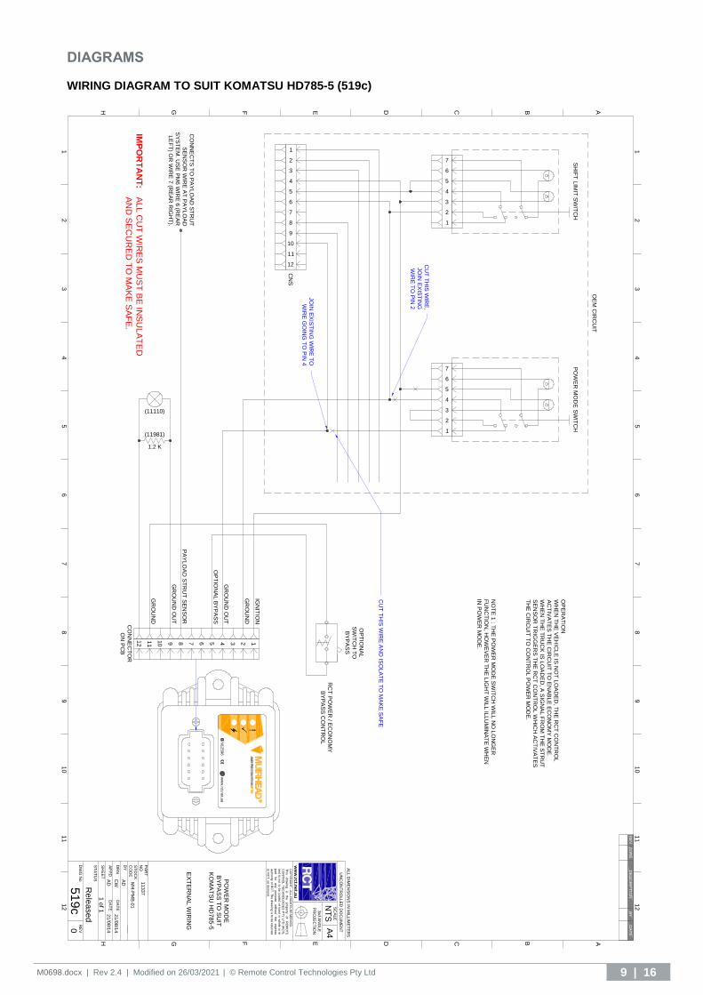
5. If you are installing to an HD785-5, cut the OEM wire coming out of the power mode switch terminal 1, 4
and 5 (Ensure that pins 1, 4 and 5 of the vehicles OEM power mode switch have been isolated and made safe). Connect the green wire (pin 4) to the existing wire going to terminal 10 of the CNS connector and connect the black wire (pin 2) to the existing wire going to terminal 6 of the CNS connector.
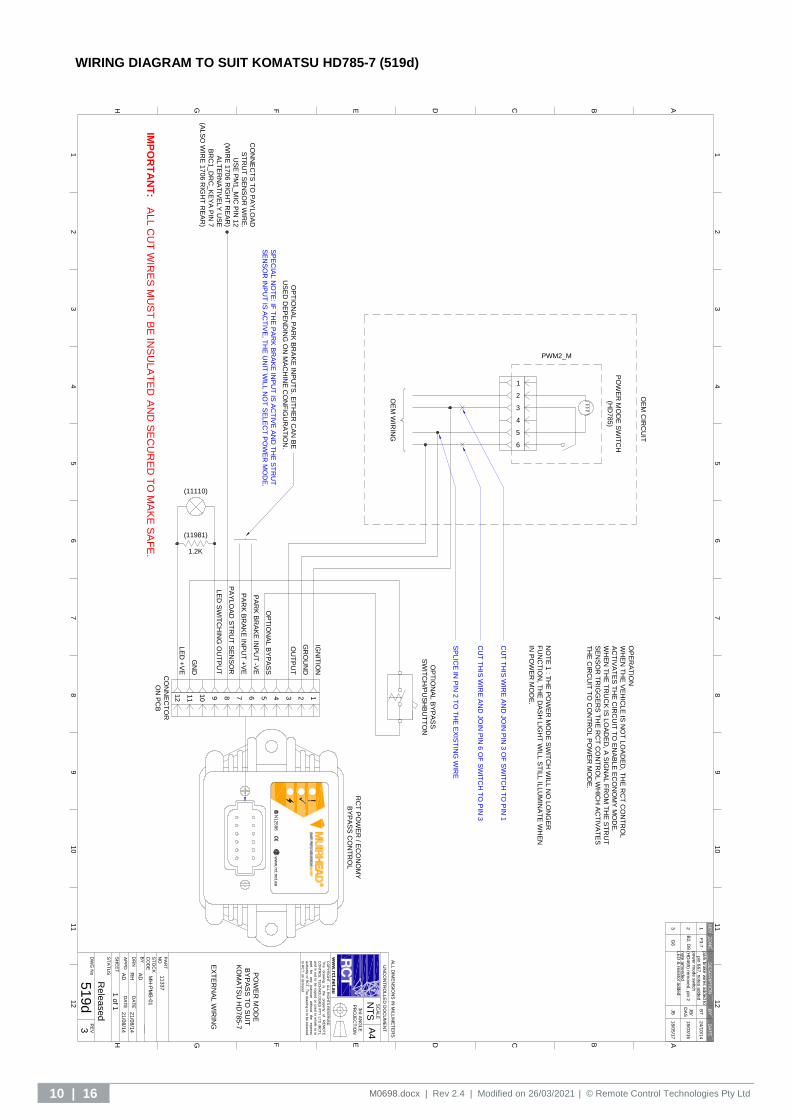
If you are installing to an HD785-7, cut the OEM wires coming out of the PWM2_M switch terminals 3 and 6. Join the OEM wire that was going to terminal 3 of the PWM2_M switch to the red wire (pin 1) and join the OEM wire that was going to terminal 6 of the PWM2_M switch to the yellow/blue wire (pin 3). Splice in the black wire (pin 2) to the OEM wire going to terminal 5 of the PWM2_M switch. Ensure any loose wires are isolated and made safe.
6. If you are installing to an HD785-5, connect the blue wire (pin 9) to pin 3 of the power mode switch.
If you are installing to an HD785-7, connect the park brake input to the orange wire (pin 6) if the signal is negative, or the pink wire (pin 7) if the signal is positive.
INSTALLATION FOR KOMATSU HD785-5 Connect wiring as per drawing 519c and as follows: WIRING CONNECTIONS
NO. COLOUR FUNCTION DESCRIPTION
1 Red Battery +VE Connect to a protected 12–24 V battery
2 Black Ground Connect to ground/battery negative
3 Yellow/Blue Output 1 Not connected (spare)
4 Green Output 3 Connect to pin 10 of CNS connector
5 White (optional) Input 1 (Optional) connected to bypass switch/pushbutton
6 Orange Input 3 Not connected
7 Pink Input 4 Not connected
8 Yellow Input 2 Connect to the payload strut sensor
9 Blue Output 4 Connect to LED –ve. This LED will be ON when the vehicle is in economy mode.
10 Purple Output 2 Not connected
11 Black/white (optional) Bypass GND (Optional) connected to bypass switch/pushbutton
12 Red/white Battery + VE Connected to LED + VE
Ensure that pins 1, 4 and 5 of the vehicles OEM power mode switch have been isolated and made safe.
8 | 16 M0698.docx | Rev 2.4 | Modified on 26/03/2021 | © Remote Control Technologies Pty Ltd
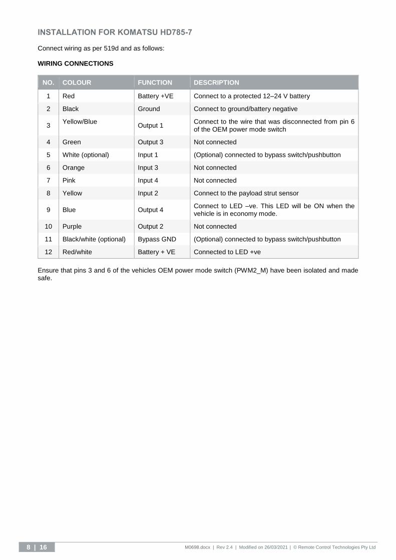
INSTALLATION FOR KOMATSU HD785-7 Connect wiring as per 519d and as follows: WIRING CONNECTIONS
NO. COLOUR FUNCTION DESCRIPTION
1 Red Battery +VE Connect to a protected 12–24 V battery
2 Black Ground Connect to ground/battery negative
3 Yellow/Blue
Output 1 Connect to the wire that was disconnected from pin 6 of the OEM power mode switch
4 Green Output 3 Not connected
5 White (optional) Input 1 (Optional) connected to bypass switch/pushbutton
6 Orange Input 3 Not connected
7 Pink Input 4 Not connected
8 Yellow Input 2 Connect to the payload strut sensor
9 Blue Output 4 Connect to LED –ve. This LED will be ON when the vehicle is in economy mode.
10 Purple Output 2 Not connected
11 Black/white (optional) Bypass GND (Optional) connected to bypass switch/pushbutton
12 Red/white Battery + VE Connected to LED +ve
Ensure that pins 3 and 6 of the vehicles OEM power mode switch (PWM2_M) have been isolated and made safe.
M0698.docx | Rev 2.4 | Modified on 26/03/2021 | © Remote Control Technologies Pty Ltd 9 | 16
DIAGRAMS WIRING DIAGRAM TO SUIT KOMATSU HD785-5 (519c)
PA
YL
OA
D S
TR
UT
SE
NS
OR
GR
OU
ND
OU
T
GR
OU
ND
IGN
ITIO
N
1
2
3
4
5
6
7
8
9
10
11
12
1
2
3
4
5
6
7
1
2
3
4
5
6
7
SH
IFT
LIM
IT S
WIT
CH
PO
WE
R M
OD
E S
WIT
CH
CN
S
OE
M C
IRC
UIT
RC
T P
OW
ER
/ EC
ON
OM
Y
BY
PA
SS
CO
NT
RO
L
CU
T T
HIS
WIR
E,
JO
IN E
XIS
TIN
G
WIR
E T
O P
IN 2
CO
NN
EC
TS
TO
PA
YL
OA
D S
TR
UT
SE
NS
OR
WIR
E A
T P
AY
LO
AD
SY
ST
EM
. US
E P
M6 W
IRE
6 (R
EA
R
LE
FT
) OR
WIR
E 7
(RE
AR
RIG
HT
).
OP
ER
AT
ION
WH
EN
TH
E V
EH
ICL
E IS
NO
T L
OA
DE
D, T
HE
RC
T C
ON
TR
OL
AC
TIV
AT
ES
TH
E C
IRC
UIT
TO
EN
AB
LE
EC
ON
OM
Y M
OD
E.
WH
EN
TH
E T
RU
CK
IS L
OA
DE
D, A
SIG
NA
L F
RO
M T
HE
ST
RU
T
SE
NS
OR
TR
IGG
ER
S T
HE
RC
T C
ON
TR
OL W
HIC
H A
CT
IVA
TE
S
TH
E C
IRC
UIT
TO
CO
NT
RO
L P
OW
ER
MO
DE
.
NO
TE
1 : T
HE
PO
WE
R M
OD
E S
WIT
CH
WIL
L N
O L
ON
GE
R
FU
NC
TIO
N, H
OW
EV
ER
TH
E L
IGH
T W
ILL IL
LU
MIN
AT
E W
HE
N
IN P
OW
ER
MO
DE
.
OP
TIO
NA
L
SW
ITC
H T
O
BY
PA
SS
CO
NN
EC
TO
R
ON
PC
B
OP
TIO
NA
L B
YP
AS
S
JO
IN E
XIS
TIN
G W
IRE
TO
WIR
E G
OIN
G T
O P
IN 4
CU
T T
HIS
WIR
E A
ND
ISO
LA
TE
TO
MA
KE
SA
FE
IMP
OR
TA
NT
:A
LL C
UT
WIR
ES
MU
ST
BE
INS
UL
AT
ED
AN
D S
EC
UR
ED
TO
MA
KE
SA
FE
.
12345678910
11
12
GR
OU
ND
OU
T
(11110)
1.2 K
(11981)
GR
OU
ND
!
ww
w.rc
t.ne
t.au
N1
25
96
12
34
56
78
910
11
12
B ACDEFGH
B ACDEFGH
12
34
56
78
910
11
12
A4
CO
PY
RIG
HT
- ALL
RIG
HT
S R
ES
ER
VE
D
This
d
raw
ing
is
th
e
pro
perty
of
RE
MO
TE
CO
NT
RO
L T
EC
HN
OLO
GIE
S P
TY
LT
D (R
CT
),
and
is n
ot to
be
copie
d o
r used
in w
ho
le o
r in
part
for
any
purp
ose
w
itho
ut
the
expre
ss
auth
ority
of R
CT
. The
dra
win
g is
to b
e re
turn
ed
to R
CT
, on d
em
and.
PO
WE
R M
OD
E
BY
PA
SS
TO
SU
IT
KO
MA
TS
U H
D7
85
-5
EX
TE
RN
AL W
IRIN
G
ww
w.rc
t.net.a
u
UN
CO
NT
RO
LLE
D D
OC
UM
EN
T
RE
V0D
WG
No
51
9c
ST
AT
US
NT
SS
CA
LE
Rele
ased
SH
EE
T1
of 1
BY
AD
DR
NC
WD
AT
E2
1/0
8/1
4
AP
PD
AD
DA
TE
21
/08/1
4
ST
OC
K
CO
DE
MH
-PM
B-0
1
PA
RT
NO
11337
3rd
AN
GLE
PR
OJE
CT
ION
AL
L D
IME
NS
ION
S IN
MIL
LIM
ET
ER
S
RE
VZ
ON
ED
ES
CR
IPT
ION
BY
DA
TE
10 | 16 M0698.docx | Rev 2.4 | Modified on 26/03/2021 | © Remote Control Technologies Pty Ltd
WIRING DIAGRAM TO SUIT KOMATSU HD785-7 (519d)
OP
TIO
NA
L B
YP
AS
S
GR
OU
ND
IGN
ITIO
N
OE
M C
IRC
UIT
CO
NN
EC
TS
TO
PA
YLO
AD
ST
RU
T S
EN
SO
R W
IRE
.
US
E P
M1_M
IC P
IN 1
2
(WIR
E 1
706 R
IGH
T R
EA
R)
ALT
ER
NA
TIV
ELY
US
E
BR
C1_D
RC
_K
EY
A P
IN 7
(ALS
O W
IRE
1706 R
IGH
T R
EA
R)
OP
ER
AT
ION
WH
EN
TH
E V
EH
ICLE
IS N
OT
LO
AD
ED
, TH
E R
CT
CO
NT
RO
L
AC
TIV
AT
ES
TH
E C
IRC
UIT
TO
EN
AB
LE
EC
ON
OM
Y M
OD
E.
WH
EN
TH
E T
RU
CK
IS L
OA
DE
D, A
SIG
NA
L F
RO
M T
HE
ST
RU
T
SE
NS
OR
TR
IGG
ER
S T
HE
RC
T C
ON
TR
OL W
HIC
H A
CT
IVA
TE
S
TH
E C
IRC
UIT
TO
CO
NT
RO
L P
OW
ER
MO
DE
.
NO
TE
1 : T
HE
PO
WE
R M
OD
E S
WIT
CH
WIL
L N
O L
ON
GE
R
FU
NC
TIO
N, T
HE
DA
SH
LIG
HT
WIL
L S
TIL
L IL
LU
MIN
AT
E W
HE
N
IN P
OW
ER
MO
DE
.
CU
T T
HIS
WIR
E A
ND
JO
IN P
IN 3
OF
SW
ITC
H T
O P
IN 1
CU
T T
HIS
WIR
E A
ND
JO
IN P
IN 6
OF
SW
ITC
H T
O P
IN 3
SP
LIC
E IN
PIN
2 T
O T
HE
EX
IST
ING
WIR
E
1
2
3
4
5
6
PO
WE
R M
OD
E S
WIT
CH
(HD
785)
PA
YLO
AD
ST
RU
T S
EN
SO
R
PWM2_M
IMP
OR
TA
NT
:A
LL
CU
T W
IRE
S M
US
T B
E IN
SU
LA
TE
D A
ND
SE
CU
RE
D T
O M
AK
E S
AF
E.
CO
NN
EC
TO
R
ON
PC
B
12345678910
11
12
RC
T P
OW
ER
/ EC
ON
OM
Y
BY
PA
SS
CO
NT
RO
L
OP
TIO
NA
L B
YP
AS
S
SW
ITC
H/P
US
HB
UT
TO
N
OU
TP
UT
GN
D
PA
RK
BR
AK
E IN
PU
T -V
E
PA
RK
BR
AK
E IN
PU
T +
VE
OP
TIO
NA
L P
AR
K B
RA
KE
INP
UT
S. E
ITH
ER
CA
N B
E
US
ED
DE
PE
ND
ING
ON
MA
CH
INE
CO
NF
IGU
RA
TIO
N.
SP
EC
IAL N
OT
E: IF
TH
E P
AR
K B
RA
KE
INP
UT
IS A
CT
IVE
AN
D T
HE
ST
RU
T
SE
NS
OR
INP
UT
IS A
CT
IVE
, TH
E U
NIT
WIL
L N
OT
SE
LE
CT
PO
WE
R M
OD
E.
!
ww
w.rc
t.ne
t.au
N1
25
96
OE
M W
IRIN
G
LE
D +
VE
LE
D S
WIT
CH
ING
OU
TP
UT
(11981)
1.2K
(11110)
12
34
56
78
91
01
11
2
B ACDEFGH
B ACDEFGH
12
34
56
78
91
01
11
2
A4
CO
PY
RIG
HT
- ALL R
IGH
TS
RE
SE
RV
ED
This
dra
win
g
is
the
pro
perty
o
f R
EM
OT
E
CO
NT
RO
L T
EC
HN
OLO
GIE
S P
TY
LT
D (R
CT
),
and
is n
ot to
be c
opie
d o
r used
in w
hole
or in
pa
rt fo
r any
purp
ose
w
ithout
the
expre
ss
auth
ority
of R
CT
. The d
raw
ing
is to
be
retu
rned
to R
CT
, on d
em
and.
PO
WE
R M
OD
E
BY
PA
SS
TO
SU
IT
KO
MA
TS
U H
D78
5-7
EX
TE
RN
AL W
IRIN
G
ww
w.rc
t.net.a
u
UN
CO
NT
RO
LLE
D D
OC
UM
EN
T
RE
V3D
WG
No
51
9d
ST
AT
US
NT
SS
CA
LE
Rele
ased
SH
EE
T1 o
f 1
BY
AD
DR
NR
HD
AT
E21/0
8/1
4
AP
PD
AD
DA
TE
21/0
8/1
4
ST
OC
K
CO
DE
MH
-PM
B-0
1
PA
RT
NO
11337
3rd
AN
GLE
PR
OJE
CT
ION
AL
L D
IME
NS
ION
S IN
MIL
LIM
ET
ER
S
RE
VZ
ON
ED
ES
CR
IPT
ION
BY
DA
TE
1F
3-7
pa
rk b
rake
wire
s a
dded to
pin
6&
7, n
ote
s a
dded
BT
24
/10
/14
2B
2, D
8p
ow
er m
od
e s
witc
h
(HD
46
5) re
mo
ve
d, p
in 2
no
te a
me
nd
ed
JB
/
DA
S1
8/0
3/1
6
3G
6
LE
D &
resis
tor a
dded
JB
18
/05
/17
M0698.docx | Rev 2.4 | Modified on 26/03/2021 | © Remote Control Technologies Pty Ltd 11 | 16
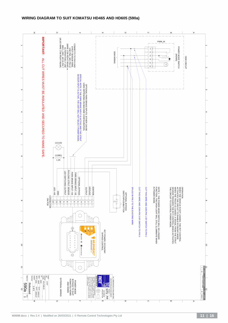
WIRING DIAGRAM TO SUIT KOMATSU HD465 AND HD605 (590a)
OP
TIO
NA
L B
YP
AS
S
GR
OU
ND
IGN
ITIO
N
OE
M C
IRC
UIT
CO
NN
EC
TS
TO
PA
YL
OA
D
ST
RU
T S
EN
SO
R W
IRE
.
US
E P
M1
_M
IC P
IN 1
2
(WIR
E 1
70
6 R
IGH
T R
EA
R)
AL
TE
RN
AT
IVE
LY
US
E
BR
C1
_D
RC
_K
EY
A P
IN 7
(AL
SO
WIR
E 1
70
6 R
IGH
T R
EA
R)
OP
ER
AT
ION
WH
EN
TH
E V
EH
ICL
E IS
NO
T L
OA
DE
D, T
HE
RC
T C
ON
TR
OL
AC
TIV
AT
ES
TH
E C
IRC
UIT
TO
EN
AB
LE
EC
ON
OM
Y M
OD
E.
WH
EN
TH
E T
RU
CK
IS L
OA
DE
D, A
SIG
NA
L F
RO
M T
HE
ST
RU
T
SE
NS
OR
TR
IGG
ER
S T
HE
RC
T C
ON
TR
OL
WH
ICH
AC
TIV
AT
ES
TH
E C
IRC
UIT
TO
CO
NT
RO
L P
OW
ER
MO
DE
.
NO
TE
1 : T
HE
PO
WE
R M
OD
E S
WIT
CH
WIL
L N
O L
ON
GE
R
FU
NC
TIO
N, T
HE
DA
SH
LIG
HT
WIL
L S
TIL
L IL
LU
MIN
AT
E W
HE
N
IN P
OW
ER
MO
DE
.
CU
T T
HIS
WIR
E A
ND
JO
IN P
IN 1
OF
SW
ITC
H T
O P
IN 1
CU
T T
HIS
WIR
E A
ND
JO
IN P
IN 3
OF
SW
ITC
H T
O P
IN 3
SP
LIC
E IN
PIN
2 T
O T
HE
EX
IST
ING
WIR
E
1
2
3
4
5
6
PA
YL
OA
D S
TR
UT
SE
NS
OR
PWM_M
CO
NN
EC
TO
R
ON
PC
B
12345678910
11
12
RC
T P
OW
ER
/ EC
ON
OM
Y
BY
PA
SS
CO
NT
RO
L
OP
TIO
NA
L B
YP
AS
S
SW
ITC
H/P
US
HB
UT
TO
N
OU
TP
UT
GN
D
PA
RK
BR
AK
E IN
PU
T -V
E
PA
RK
BR
AK
E IN
PU
T +
VE
OP
TIO
NA
L P
AR
K B
RA
KE
INP
UT
S. E
ITH
ER
CA
N B
E
US
ED
DE
PE
ND
ING
ON
MA
CH
INE
CO
NF
IGU
RA
TIO
N.
SP
EC
IAL
NO
TE
: IF T
HE
PA
RK
BR
AK
E IN
PU
T IS
AC
TIV
E A
ND
TH
E S
TR
UT
SE
NS
OR
INP
UT
IS A
CT
IVE
, TH
E U
NIT
WIL
L N
OT
SE
LE
CT
PO
WE
R M
OD
E.
!
ww
w.rc
t.net.a
uN
12596
PO
WE
R M
OD
E S
WIT
CH
(HD
46
5)
OE
M W
IRIN
G
IMP
OR
TA
NT
:A
LL C
UT
WIR
ES
MU
ST
BE
INS
ULA
TE
D A
ND
SE
CU
RE
D T
O M
AK
E S
AF
E.
LE
D +
VE
LE
D S
WIT
CH
ING
OU
TP
UT
(11981)
1.2K
(11110)
12
34
56
78
91
01
11
2
B ACDEFGH
B ACDEFGH
12
34
56
78
91
01
11
2
A4
CO
PY
RIG
HT
- ALL R
IGH
TS
RE
SE
RV
ED
This
d
raw
ing
is
th
e
pro
perty
o
f R
EM
OT
E
CO
NT
RO
L T
EC
HN
OL
OG
IES
PT
Y L
TD
(RC
T),
and
is n
ot to
be c
op
ied
or u
sed
in w
ho
le o
r in
pa
rt fo
r a
ny
purp
ose
w
itho
ut
the
exp
ress
auth
ority
of R
CT
. The d
raw
ing
is to
be
retu
rned
to R
CT
, on d
em
and.
PO
WE
R M
OD
E
BY
PA
SS
TO
SU
IT
KO
MA
TS
U H
D465
AN
D H
D605
EX
TE
RN
AL W
IRIN
G
ww
w.rc
t.net.a
u
UN
CO
NT
RO
LLE
D D
OC
UM
EN
T
RE
V1D
WG
No
59
0a
ST
AT
US
NT
SS
CA
LE
Rele
ased
SH
EE
T1 o
f 1
BY
DA
S
DR
NJE
NT
DA
TE
25
/01
/17
AP
PD
DA
SD
AT
E2
5/0
1/1
7
ST
OC
K
CO
DE
MH
-PM
B-0
1
PA
RT
NO
11
337
3rd
AN
GLE
PR
OJE
CT
ION
AL
L D
IME
NS
ION
S IN
MIL
LIM
ET
ER
S
RE
VZ
ON
ED
ES
CR
IPT
ION
BY
DA
TE
1G
6L
ED
& re
sis
tor a
dded
JB
18
/05
/17

12 | 16 M0698.docx | Rev 2.4 | Modified on 26/03/2021 | © Remote Control Technologies Pty Ltd
CALIBRATION
SETTING NO. DESCRIPTION UNITS* DEFAULT
1** Override Time
The length of time the economy bypass switch will allow the unit to force power mode, adjustable between 0 and 3 minutes.
Seconds 30
2** Truck Load Time
The length of time the controller will wait to engage power mode once the correct weight has been sensed (this is used to stop false changes), adjustable between 0 and 30 seconds.
Seconds 2
3** Analogue On Weight
The weight at which the unit will engage power mode, a signal greater than this value will still trigger this effect, adjustable between 0 and 24 volts.
V 3.515 V
4** Analogue Off Weight
The weight at which the unit will engage economy mode, a signal smaller than this value will still trigger this effect, adjustable between 0 and 24 volts.
V 2.49 V
* Note: The units’ column indicates the value that setting will increase by with each increment.
**Note: These parameters can be changed through programming; however, this will require the use of the
programmable controller utility available from RCT.
The following diagram is a visual representation of how the controller reacts to changes in voltage sensed from
the sensor struts:
In reference to the diagram above:
A If the voltage is within this range, the device will trigger (or remain in) economy mode. By default, this range is 2.49 V or below.
B If the voltage is within this range, the device output will remain in whatever state it was in prior to entering this range, until the voltage moves outside of this range. By default, this range is 2.50 V - 3.514 V.
C If the voltage is within this range, the device will trigger (or remain in) power mode. By default, this range is 3.515 V or above.
D This point represents the analogue off weight, 2.49 V by default.
E This point represents the analogue on weight, 3.515 V by default.
SERVICE INFORMATION
SERVICE SCHEDULE
The manufacturer recommends that the following service procedure should be performed at each machine’s scheduled service interval.
SERVICE PROCEDURE
1. Perform a visual inspection; include the following:
a) Control unit.
b) Wiring connections and looms.
c) Check that all switches and solenoids are in good working condition.
2. Perform a system test as per the Operation and Use section of this manual for the operation of the controller.

M0698.docx | Rev 2.4 | Modified on 26/03/2021 | © Remote Control Technologies Pty Ltd 13 | 16
PARTS LIST
12731 POWER ECONOMY BYPASS KIT
PART NO. DESCRIPTION
QUANTITY
INCLUDED PARTS
SUGGESTED SPARES
11337 Power mode bypass controller 1 1
11110 Green LED 1 -
11981 LED resistor 1 -
12731 Power economy bypass kit 1 -
12738 Generic loom 1 -
7919 Bypass switch 1 -
3214 Switch cover 1 -
13617 System override label 1 -
TECHNICAL SPECIFICATIONS
Dimensions, controller only Length: 119 mm | Width: 80 mm | Height/Depth: 65 mm
Dimensions, boxed for freight Length: 140 mm | Width: 140 mm | Height/Depth: 70 mm
Weight, controller only 255 g
Weight, including loom / packaging for freight
600 g
Input nominal voltage 12 to 24 V
Ignition output continuous current maximum
10 A
Auxiliary output continuous current maximum
0.7 A
Operating temperate range −40 °C to +85 °C
Connection types 12-pin receptacle
Inputs Ignition supply, battery supply, chassis ground
Min & max input voltage 9 to 35 V DC
Enclosure type ABS
Environmental protection IP rating IP65
Programming/adjustment Refer to Calibration section.
14 | 16 M0698.docx | Rev 2.4 | Modified on 26/03/2021 | © Remote Control Technologies Pty Ltd
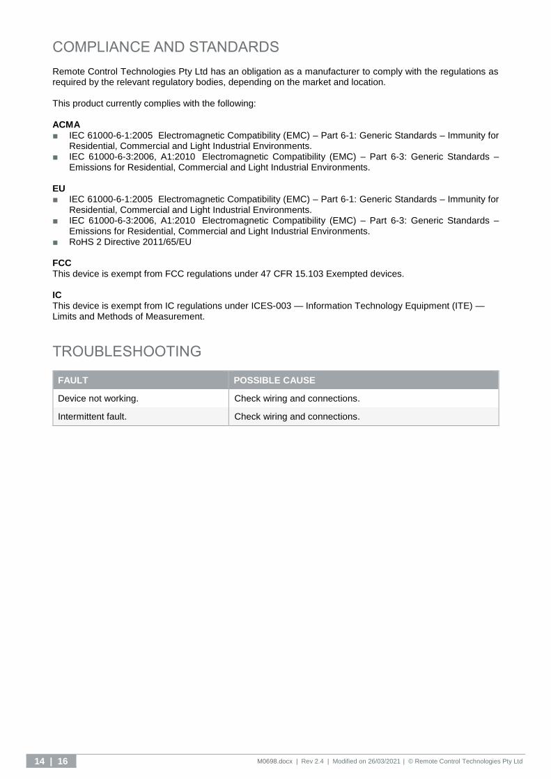
COMPLIANCE AND STANDARDS Remote Control Technologies Pty Ltd has an obligation as a manufacturer to comply with the regulations as required by the relevant regulatory bodies, depending on the market and location.
This product currently complies with the following:
ACMA ■ IEC 61000-6-1:2005 Electromagnetic Compatibility (EMC) – Part 6-1: Generic Standards – Immunity for
Residential, Commercial and Light Industrial Environments. ■ IEC 61000-6-3:2006, A1:2010 Electromagnetic Compatibility (EMC) – Part 6-3: Generic Standards –
Emissions for Residential, Commercial and Light Industrial Environments. EU ■ IEC 61000-6-1:2005 Electromagnetic Compatibility (EMC) – Part 6-1: Generic Standards – Immunity for
Residential, Commercial and Light Industrial Environments. ■ IEC 61000-6-3:2006, A1:2010 Electromagnetic Compatibility (EMC) – Part 6-3: Generic Standards –
Emissions for Residential, Commercial and Light Industrial Environments. ■ RoHS 2 Directive 2011/65/EU FCC This device is exempt from FCC regulations under 47 CFR 15.103 Exempted devices.
IC This device is exempt from IC regulations under ICES-003 — Information Technology Equipment (ITE) — Limits and Methods of Measurement.
TROUBLESHOOTING
FAULT POSSIBLE CAUSE
Device not working. Check wiring and connections.
Intermittent fault. Check wiring and connections.
M0698.docx | Rev 2.4 | Modified on 26/03/2021 | © Remote Control Technologies Pty Ltd 15 | 16
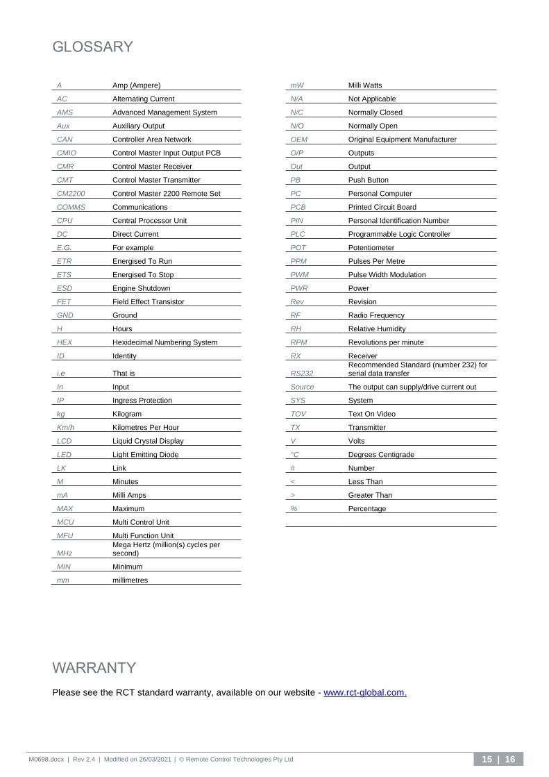
GLOSSARY
WARRANTY Please see the RCT standard warranty, available on our website - www.rct-global.com.
A Amp (Ampere)
mW Milli Watts
AC Alternating Current
N/A Not Applicable
AMS Advanced Management System
N/C Normally Closed
Aux Auxiliary Output
N/O Normally Open
CAN Controller Area Network
OEM Original Equipment Manufacturer
CMIO Control Master Input Output PCB
O/P Outputs
CMR Control Master Receiver
Out Output
CMT Control Master Transmitter
PB Push Button
CM2200 Control Master 2200 Remote Set
PC Personal Computer
COMMS Communications
PCB Printed Circuit Board
CPU Central Processor Unit
PIN Personal Identification Number
DC Direct Current
PLC Programmable Logic Controller
E.G. For example
POT Potentiometer
ETR Energised To Run
PPM Pulses Per Metre
ETS Energised To Stop
PWM Pulse Width Modulation
ESD Engine Shutdown
PWR Power
FET Field Effect Transistor
Rev Revision
GND Ground
RF Radio Frequency
H Hours
RH Relative Humidity
HEX Hexidecimal Numbering System
RPM Revolutions per minute
ID Identity
RX Receiver
i.e That is
RS232 Recommended Standard (number 232) for serial data transfer
In Input
Source The output can supply/drive current out
IP Ingress Protection
SYS System
kg Kilogram
TOV Text On Video
Km/h Kilometres Per Hour
TX Transmitter
LCD Liquid Crystal Display
V Volts
LED Light Emitting Diode
°C Degrees Centigrade
LK Link
# Number
M Minutes
< Less Than
mA Milli Amps
> Greater Than
MAX Maximum
% Percentage
MCU Multi Control Unit
MFU Multi Function Unit
MHz Mega Hertz (million(s) cycles per second)
MIN Minimum
mm millimetres

Discover more: www.rct-global.com [email protected] AUSTRALIA: +61 (0) 8 9353 6577 AFRICA: +27 (0) 83 292 4246 CANADA: +1 705 590 4001 RUSSIA / CIS: +7 (910) 411 11-74 SOUTH AMERICA: +56 3 5229 9409 USA: +1 801 938 9214