polymer aluminum electrolytic capacitors - murata …/media/webrenewal/campaign/ads/... ·...
TRANSCRIPT

Technical Guide
www.murataamericas.com/polymer_al
Product Guide
POLYMER
Aluminum ElectrolyticCapacitorsECAS Series
Polymer Aluminum Electrolytic Capacitors
2
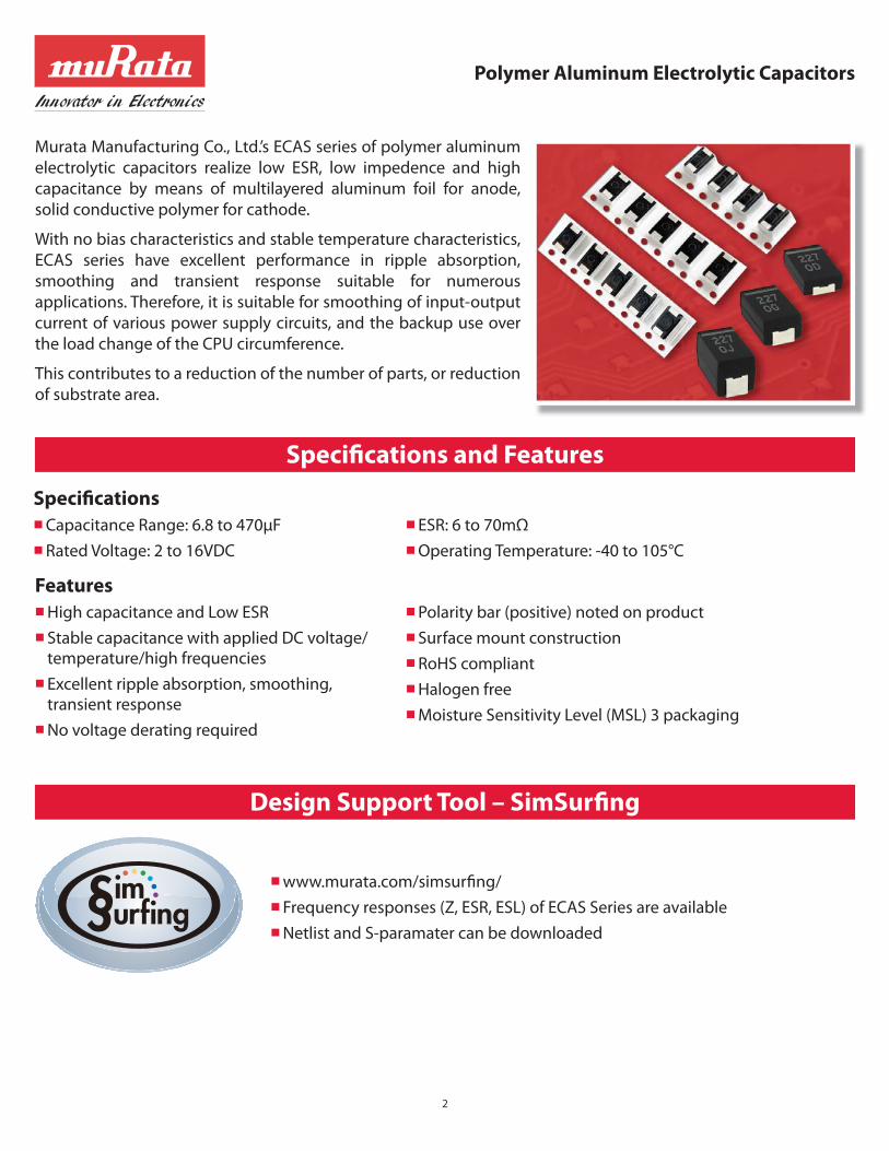
Murata Manufacturing Co., Ltd.’s ECAS series of polymer aluminum
electrolytic capacitors realize low ESR, low impedence and high
capacitance by means of multilayered aluminum foil for anode,
solid conductive polymer for cathode.
With no bias characteristics and stable temperature characteristics,
ECAS series have excellent performance in ripple absorption,
smoothing and transient response suitable for numerous
applications. Therefore, it is suitable for smoothing of input-output
current of various power supply circuits, and the backup use over
the load change of the CPU circumference.
This contributes to a reduction of the number of parts, or reduction
of substrate area.
Specifi cations Capacitance Range: 6.8 to 470μF
Rated Voltage: 2 to 16VDC
ESR: 6 to 70mΩ
Operating Temperature: -40 to 105°C
FeaturesHigh capacitance and Low ESR
Stable capacitance with applied DC voltage/ temperature/high frequencies
Excellent ripple absorption, smoothing, transient response
No voltage derating required
Polarity bar (positive) noted on product
Surface mount construction
RoHS compliant
Halogen free
Moisture Sensitivity Level (MSL) 3 packaging
www.murata.com/simsurfi ng/
Frequency responses (Z, ESR, ESL) of ECAS Series are available
Netlist and S-paramater can be downloaded
Specifi cations and Features
Design Support Tool – SimSurfi ng

Polymer Aluminum Electrolytic Capacitors
3
100
10
1
0.1
0.01
0.001
1 10 100
Capacitance (μF) at 120Hz
1000 10000
ES
R (
oh
m)
at
10
0kH
z
Ta Capacitor(MnO2)
Ta Capacitor(Polymer)
Al Capacitor(Can Type/Electrolyte)
Al Capacitor(Can Type/Polymer)
MLCC
ECAS Series
Capacitance Value (μF)
6.8 10 15 22 33 47 56 68 82 100 150 180 220 330 470
Vo
lta
ge
(V
DC
)
2D416
D49
D49
D67
D66
4D420
D416
D416
D612
D610
D98
6.3D455
D445
D425
D425
D415
D415
D610
D610
D910
10D455
D428
D425
D425
D615
D910
D910
12.5D455
D445
D430
D425
D620
D620
D912
16D470
D460
D440
D630
D46
Case Size Code
ESR (mΩ)Mass Production
POLYMER & MLCC
SOLUTIONS
POLYMER SOLUTIONS
NEW!
NEW! NEW!
NEW!
Product Lineup
Capacitor Map (Cap & ESR)
Capacitor
8.8
(in mm)
2.8
4.0
Reflow times: 2 times max
50
100
150
200
250
Te
mp
. (°
C)
160sec max(150 to 195°C)
10sec max(Peak temp.: 245°C max)
60sec max(225°C and over)
Time (sec)
115sec max(195°Cand over)
Polymer Aluminum Electrolytic Capacitors
4
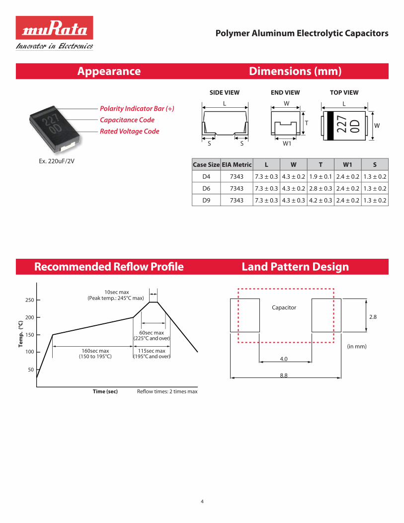
Appearance Dimensions (mm)
Recommended Refl ow Profi le Land Pattern Design
Case Size EIA Metric L W T W1 S
D4 7343 7.3 ± 0.3 4.3 ± 0.2 1.9 ± 0.1 2.4 ± 0.2 1.3 ± 0.2
D6 7343 7.3 ± 0.3 4.3 ± 0.2 2.8 ± 0.3 2.4 ± 0.2 1.3 ± 0.2
D9 7343 7.3 ± 0.3 4.3 ± 0.3 4.2 ± 0.3 2.4 ± 0.2 1.3 ± 0.2
W1
T
W
S S
L
SIDE VIEW END VIEW TOP VIEW
W227
0D
L
Ex. 220uF/2V
Polarity Indicator Bar (+)
Capacitance Code
Rated Voltage Code

-40
-20
0
20
40
-50 -25 0 25 50 75 100 125
Ca
pa
cita
nce
Ch
an
ge
(%
)
Temperature (°C )
Temperature Characteristics of Capacitance
Representative Data
No Bias
50% of Rated Voltage
0 25 50 75 100-40
-20
0
20
40
Ca
pa
cita
nce
Ch
an
ge
(%
)
Bias Voltage / Rated Voltage (%)
DC Bias Characteristics
Representative Data
Polymer Aluminum Electrolytic Capacitors
5
Characteristics
0.001
0.01
0.1
1
10
1 10 100 1,000 10,000 100,000
ES
R o
r Z
(Ω
)
Frequency (kHz)
Low ESR & Z
ECASD60D477M006K00ECASD60J157M010K00ECASD61C226M030K00Z
ESR
Polymer Aluminum Electrolytic Capacitors
6
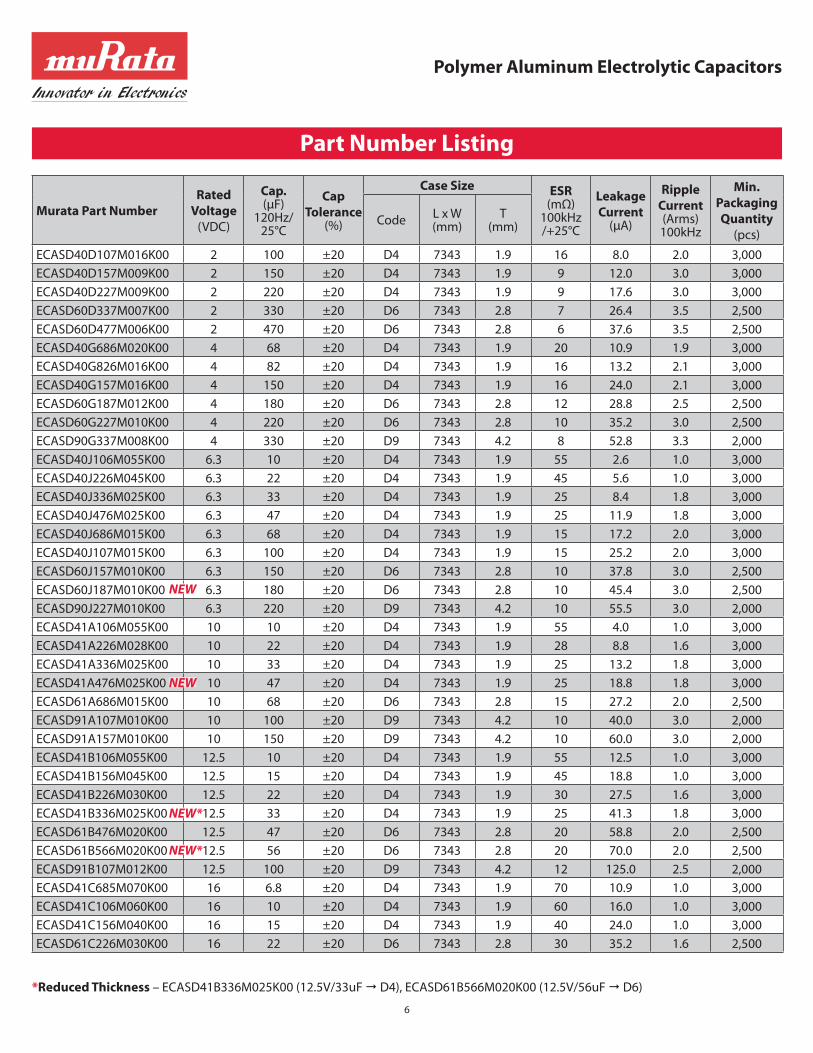
Murata Part NumberRated
Voltage (VDC)
Cap. (μF)
120Hz/ 25°C
CapTolerance
(%)
Case Size ESR(mΩ)
100kHz /+25°C
LeakageCurrent
(μA)
RippleCurrent (Arms)100kHz
Min.PackagingQuantity
(pcs)Code
L x W(mm)
T(mm)
ECASD40D107M016K00 2 100 ±20 D4 7343 1.9 16 8.0 2.0 3,000
ECASD40D157M009K00 2 150 ±20 D4 7343 1.9 9 12.0 3.0 3,000
ECASD40D227M009K00 2 220 ±20 D4 7343 1.9 9 17.6 3.0 3,000
ECASD60D337M007K00 2 330 ±20 D6 7343 2.8 7 26.4 3.5 2,500
ECASD60D477M006K00 2 470 ±20 D6 7343 2.8 6 37.6 3.5 2,500
ECASD40G686M020K00 4 68 ±20 D4 7343 1.9 20 10.9 1.9 3,000
ECASD40G826M016K00 4 82 ±20 D4 7343 1.9 16 13.2 2.1 3,000
ECASD40G157M016K00 4 150 ±20 D4 7343 1.9 16 24.0 2.1 3,000
ECASD60G187M012K00 4 180 ±20 D6 7343 2.8 12 28.8 2.5 2,500
ECASD60G227M010K00 4 220 ±20 D6 7343 2.8 10 35.2 3.0 2,500
ECASD90G337M008K00 4 330 ±20 D9 7343 4.2 8 52.8 3.3 2,000
ECASD40J106M055K00 6.3 10 ±20 D4 7343 1.9 55 2.6 1.0 3,000
ECASD40J226M045K00 6.3 22 ±20 D4 7343 1.9 45 5.6 1.0 3,000
ECASD40J336M025K00 6.3 33 ±20 D4 7343 1.9 25 8.4 1.8 3,000
ECASD40J476M025K00 6.3 47 ±20 D4 7343 1.9 25 11.9 1.8 3,000
ECASD40J686M015K00 6.3 68 ±20 D4 7343 1.9 15 17.2 2.0 3,000
ECASD40J107M015K00 6.3 100 ±20 D4 7343 1.9 15 25.2 2.0 3,000
ECASD60J157M010K00 6.3 150 ±20 D6 7343 2.8 10 37.8 3.0 2,500
ECASD60J187M010K00 6.3 180 ±20 D6 7343 2.8 10 45.4 3.0 2,500
ECASD90J227M010K00 6.3 220 ±20 D9 7343 4.2 10 55.5 3.0 2,000
ECASD41A106M055K00 10 10 ±20 D4 7343 1.9 55 4.0 1.0 3,000
ECASD41A226M028K00 10 22 ±20 D4 7343 1.9 28 8.8 1.6 3,000
ECASD41A336M025K00 10 33 ±20 D4 7343 1.9 25 13.2 1.8 3,000
ECASD41A476M025K00 10 47 ±20 D4 7343 1.9 25 18.8 1.8 3,000
ECASD61A686M015K00 10 68 ±20 D6 7343 2.8 15 27.2 2.0 2,500
ECASD91A107M010K00 10 100 ±20 D9 7343 4.2 10 40.0 3.0 2,000
ECASD91A157M010K00 10 150 ±20 D9 7343 4.2 10 60.0 3.0 2,000
ECASD41B106M055K00 12.5 10 ±20 D4 7343 1.9 55 12.5 1.0 3,000
ECASD41B156M045K00 12.5 15 ±20 D4 7343 1.9 45 18.8 1.0 3,000
ECASD41B226M030K00 12.5 22 ±20 D4 7343 1.9 30 27.5 1.6 3,000
ECASD41B336M025K00 12.5 33 ±20 D4 7343 1.9 25 41.3 1.8 3,000
ECASD61B476M020K00 12.5 47 ±20 D6 7343 2.8 20 58.8 2.0 2,500
ECASD61B566M020K00 12.5 56 ±20 D6 7343 2.8 20 70.0 2.0 2,500
ECASD91B107M012K00 12.5 100 ±20 D9 7343 4.2 12 125.0 2.5 2,000
ECASD41C685M070K00 16 6.8 ±20 D4 7343 1.9 70 10.9 1.0 3,000
ECASD41C106M060K00 16 10 ±20 D4 7343 1.9 60 16.0 1.0 3,000
ECASD41C156M040K00 16 15 ±20 D4 7343 1.9 40 24.0 1.0 3,000
ECASD61C226M030K00 16 22 ±20 D6 7343 2.8 30 35.2 1.6 2,500
Part Number Listing
NEW
NEW
NEW*
NEW*
*Reduced Thickness – ECASD41B336M025K00 (12.5V/33uF D4), ECASD61B566M020K00 (12.5V/56uF D6)

Applications
Market Set/Application Overall Power Management
Computer
Notebook/Netbook
Server
Motherboard/Graphics Card
Multifunction Peripheral (Copier/Printer)
Digital AV
Digital TV (LCD/Plasma)
Game Console
Set Top Box
Telecom
Network/Switch/Router
Base Station
t
V
V
I
tt
V
Cap
IC on ESL ESR
CPUASICFPGAetc.
PowerSupply
Target
c Eliminates High Frequency Noise from IC
c Stabilizes Voltage Source
c Eliminates Ripple
c Smoothes Voltage Source
c Peak Power Assistance
t
I
Power supplyfrom ECAS
Power supplyfrom Battery
USB2.0USB3.0
IC
5V USBPort
Target
Ex.1) Power Supply line around IC etc.
Ex. 2) USB bus power line
Polymer Aluminum Electrolytic Capacitors
7
ECAS D4 0D 227 M 009 K 00
➀ ➁ ➂ ➃ ➄ ➅ ➆ ➇➀ Series
ECAS Polymer Al Electrolytic Capacitor
➁ Dimension (L×W×T) (mm)Code L W T
D4 7.3 ± 0.3 4.3 ± 0.2 1.9 ± 0.1
D6 7.3 ± 0.3 4.3 ± 0.2 2.8 ± 0.3
D9 7.3 ± 0.3 4.3 ± 0.3 4.2 ± 0.3
➂ Rated Voltage Code Rated Voltage
0D DC 2V
0G DC 4V
0J DC 6.3V
1A DC 10V
1B DC 12.5V
1C DC 16V
➃ CapacitanceExpressed by three-digit numeric code. The unit is microfarad (μF). The fi rst and second fi gures are signifi cant digits, and the third fi gure expresses the number of zeros that follow the two fi gures.
Code Capacitance
476 47μF
107 100μF
227 220μF
477 470μF
➄ Capacitance ToleranceCode Capacitance Tolerance
Ex. M ±20%
➅ ESRExpressed by three-digit alphanumerics. The unit is milli-ohm (mΩ). If there is a decimal point, it is expressed by the capital letter “R.”
Code ESR
Ex.
4R5 4.5mΩ009 9mΩ010 10mΩ
➆ PackagingCode Packaging
K ø330mm Embossed Tape
➇ Inhouse Specifi cation Code Expressed by two fi gures.
Part Number Description
Polymer Aluminum Electrolytic Capacitors
8
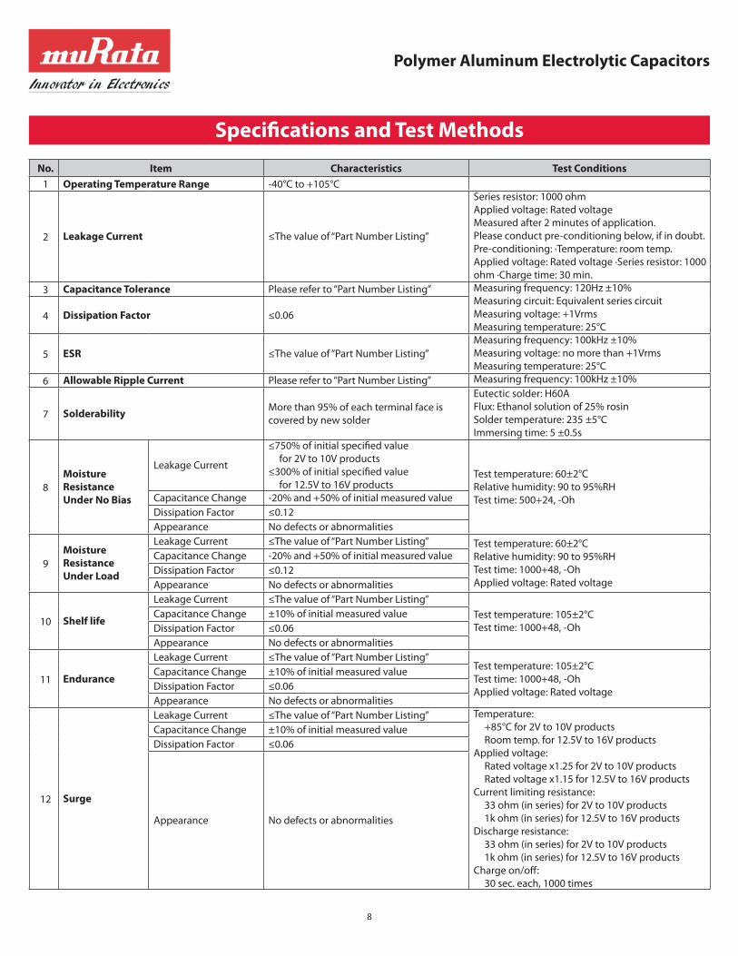
No. Item Characteristics Test Conditions
1 Operating Temperature Range -40°C to +105°C
2 Leakage Current ≤The value of “Part Number Listing”
Series resistor: 1000 ohm Applied voltage: Rated voltageMeasured after 2 minutes of application.Please conduct pre-conditioning below, if in doubt.Pre-conditioning: ·Temperature: room temp. Applied voltage: Rated voltage ·Series resistor: 1000 ohm ·Charge time: 30 min.
3 Capacitance Tolerance Please refer to “Part Number Listing” Measuring frequency: 120Hz ±10%Measuring circuit: Equivalent series circuitMeasuring voltage: +1VrmsMeasuring temperature: 25°C
4 Dissipation Factor ≤0.06
5 ESR ≤The value of “Part Number Listing”
Measuring frequency: 100kHz ±10%Measuring voltage: no more than +1VrmsMeasuring temperature: 25°C
6 Allowable Ripple Current Please refer to “Part Number Listing” Measuring frequency: 100kHz ±10%
7 SolderabilityMore than 95% of each terminal face is covered by new solder
Eutectic solder: H60AFlux: Ethanol solution of 25% rosinSolder temperature: 235 ±5°CImmersing time: 5 ±0.5s
8
Moisture Resistance Under No Bias
Leakage Current
≤750% of initial specifi ed value for 2V to 10V products≤300% of initial specifi ed value for 12.5V to 16V products
Test temperature: 60±2°C Relative humidity: 90 to 95%RHTest time: 500+24, -OhCapacitance Change -20% and +50% of initial measured value
Dissipation Factor ≤0.12
Appearance No defects or abnormalities
9
Moisture Resistance Under Load
Leakage Current ≤The value of “Part Number Listing” Test temperature: 60±2°C Relative humidity: 90 to 95%RHTest time: 1000+48, -OhApplied voltage: Rated voltage
Capacitance Change -20% and +50% of initial measured value
Dissipation Factor ≤0.12
Appearance No defects or abnormalities
10 Shelf life
Leakage Current ≤The value of “Part Number Listing”
Test temperature: 105±2°C Test time: 1000+48, -Oh
Capacitance Change ±10% of initial measured value
Dissipation Factor ≤0.06
Appearance No defects or abnormalities
11 Endurance
Leakage Current ≤The value of “Part Number Listing”Test temperature: 105±2°C
Test time: 1000+48, -OhApplied voltage: Rated voltage
Capacitance Change ±10% of initial measured value
Dissipation Factor ≤0.06
Appearance No defects or abnormalities
12 Surge
Leakage Current ≤The value of “Part Number Listing” Temperature: +85°C for 2V to 10V products Room temp. for 12.5V to 16V products
Applied voltage: Rated voltage x1.25 for 2V to 10V products Rated voltage x1.15 for 12.5V to 16V products
Current limiting resistance: 33 ohm (in series) for 2V to 10V products 1k ohm (in series) for 12.5V to 16V productsDischarge resistance: 33 ohm (in series) for 2V to 10V products
1k ohm (in series) for 12.5V to 16V productsCharge on/off : 30 sec. each, 1000 times
Capacitance Change ±10% of initial measured value
Dissipation Factor ≤0.06
Appearance No defects or abnormalities
Specifi cations and Test Methods
Polymer Aluminum Electrolytic Capacitors
9
CAUTIONS
1. Prohibited Circuits ECAS series cannot be used on the following circuits.
➀ Time constant circuits ➂ The circuits in which two or more ECAS series are connected in a series so as to raise the endurance voltage➁ Coupling circuits ➃ Circuits greatly aff ected by leakage current
2. Polarity Polymer aluminum electrolytic capacitor is polarized. Please not to reverse the polarity when using. If reverse voltage is applied, it may damage the oxide fi lm and the capacitor itself.
3. Operating Voltage When DC-rated capacitors are to be used in AC or ripple current circuits, be sure to maintain the Vp-p value of the applied voltage or the Vo-p which contains DC bias within the rated voltage range. When the voltage is applied to the circuit, starting or stopping may generate irregular voltage for a transit period because of resonance or switching. Be sure to use a capacitor with a rated voltage range that includes these irregular voltages.
4. Inrush Current Extreme inrush current may cause short circuit or leakage current increase. If the inrush current exceeds 20A, adding protection circuit is recommended.
5. Allowable Ripple Current Please not to apply ripple current exceeding the allowable value specifi ed in this document. If excessive current is applied, it may generate heat and the heat may damage the capacitor. The sum of DC voltage and the peak AC voltage shall not exceed the rated voltage. The sum of the DC voltage and the peak AC voltage shall not allow a voltage reversal. Maximum allowable ripple current = Allowable Ripple Current x *Temperature Compensation Coeffi cient *Temperature Compensation Coeffi cient = 1.00(TB45°C), 0.70(45°C<TB85°C), 0.25(85°C<TB105°C)
6. Operating Temperature The operating temperature limit depends on the capacitor. ➀ Do not apply temperature exceeding the upper operating temperature. It is necessary to select a capacitor with a suitable rated temperature that will cover the operating temperature range. Also it is necessary to consider the temperature distribution in equipment and the seasonal temperature variable factor. ➁ Consider the self-heating of the capacitor. The surface temperature of the capacitor shall be the upper operating temperature or less when including the self-heating factors.
7. Refl ow Soldering Please not to apply excessive force to the capacitor during insertion as well as after soldering. The excessive force may result in damage to electrode terminals and/or degradation of electrical performance.
8. Operating Environment Confi rm the environment in which the equipment will operate is under the specifi ed conditions. Do not use the equipment under the following environments.
➀ Being spattered with water or oil. ➃ Being exposed to toxic gas (e.g., hydrogen sulfi de, sulfur dioxide, chlorine, ammonia gas, etc.)➁ Being exposed to direct sunlight. ➄ Being exposed to excessive vibrations or mechanical shocks.➂ Being exposed to Ozone, ultraviolet
rays or radiation.➅ Being exposed to condensable environments.
9. Failure Rate The failure rate is 0.5%/1,000h (60% Reliability) based on JIS C 5003.
Caution Before Use

Polymer Aluminum Electrolytic Capacitors
10
TypeCavity Size (mm) Minimum
Qty. (pcs.)Reel Size
Tape Width
A B W W1A±0.2 B±0.2 C±0.2 D
D4 4.5 7.6 2.2 0.4 max. 3,000 ø330 12 330.0±2.0 100.0±1.0 17.5±1.5 13.5±1.5
D6 4.5 7.6 3.2 0.4 max. 2,500
D9 4.5 7.6 4.6 0.4 max. 2,000
2.0±0.1
A
D
C
B
4.0±0.1
Polarity
(in mm)
(-)
(+)
8.0±0.1
12.0
±0.
3
5.5±
0.1
1.75
±0.
1
1.5
1.5+0.25–0
+0.1–0
(in mm)
W
2.0±0.5
ø13±0.2
ø21±0.8
W1
AB
Packaging
STORAGE CONDITIONS
1. Term of warranty for this product is two years after packaging in a moisture-proof bag, under the conditions below with sealed packaging. Recommended storage environment: Room temperature: 5-30°C; Humidity: no more than 60%RH
2. Polymer aluminum electrolytic capacitors should not be stored in an atmosphere consisting of corrosive gas (e.g., hydrogen sulfi de, sulfur dioxide, chlorine, ammonia gas, etc.).
3. Polymer aluminum electrolytic capacitors should be stored in a dry atmosphere, avoiding direct sunlight and condensation. If capacitors are kept at a higher humidity, the following problems may occur: ➀Leakage current will increase at the beginning of use and damage the circuit. ➁Moisture absorbed in a resin will evaporate and expand with heat of mounting and damage the mold resin.
4. Please confi rm a dry state with a humidity indicator card after open immediately. If 20% indication was in a pink state after opened, it is
recommended to bake under the conditions below as countermeasures against the problems ➀ and ➁ in item 3 above respectively.
5. The capacitors should be kept dry using desiccators or any other methods after unsealing the moisture-proof packaging. If more than two weeks has passed under the recommended storage environment specifi ed above after unsealing the packaging, it is recommended to apply voltage and to bake under the conditions below, as countermeasures against the problems ➀ and ➁ in item 3 above respectively.
➀ Recommended voltage conditions: ➁ Recommended baking conditions:
Applied voltage: rated voltage Temperature: 60 (+0, -5) °C
Time: 30 minutes Time: 168 hours
➀ Temperature: room temperature
Current limiting resistance: 1000Ω (series connection)
6. This product meets Moisture Sensitivity Level (MSL) 3 packaging.

Polymer Aluminum Electrolytic Capacitors
11
Supplier Series Cross Reference
Notes
Manufacturer P/N Prefi x / Series Brand MuRata Series Name
Panasonic EEF SP-Cap MuRata ECAS
Kemet A700 AO-CAP MuRata ECAS
Showa Denko A705 SDK-CAP MuRata ECAS
Rubycon SXB, SXE, SW PC-CON MuRata ECAS
NIC NSP, NPC - MuRata ECAS
Cornell Dublier ESR, SPA, SPSX, SPCX - MuRata ECAS
_________________________________________________________________________________________________________________________
_________________________________________________________________________________________________________________________
_________________________________________________________________________________________________________________________
_________________________________________________________________________________________________________________________
_________________________________________________________________________________________________________________________
_________________________________________________________________________________________________________________________
_________________________________________________________________________________________________________________________
_________________________________________________________________________________________________________________________
_________________________________________________________________________________________________________________________
_________________________________________________________________________________________________________________________
_________________________________________________________________________________________________________________________
_________________________________________________________________________________________________________________________
_________________________________________________________________________________________________________________________
_________________________________________________________________________________________________________________________
_________________________________________________________________________________________________________________________
_________________________________________________________________________________________________________________________
_________________________________________________________________________________________________________________________

www.murataamericas.com/polymer_al© June 1, 2012 Murata Americas
Note:1. Export Control <For customers outside Japan> Murata products should not be used or sold for use in the development, production, stockpiling or utilization
of any conventional weapons or mass-destructive weapons (nuclear weapons, chemical or biological weapons, or missiles), or any other weapons. <For customers in Japan> For products which are controlled items subject to the “Foreign Exchange and Foreign Trade Law” of Japan, the export license
specified by the law is required for export. 2. Please contact our sales representatives or product engineers before using the products in this catalog for the applications listed below, which require especially
high reliability for the prevention of defects which might directly damage a third party’s life, body or property, or when one of our products is intended for use in applications other than those specified in this catalog. ① Aircraft equipment ➁ Aerospace equipment ➂ Undersea equipment ➃ Power plant equipment➄ Medical equipment ➅ Transportation equipment (vehicles, trains, ships, etc.)➆ Traffi c signal equipment ➇ Disaster prevention / crime prevention equipment➈ Data-processing equipment ➉ Application of similar complexity and/or reliability requirements to the applications listed above.
3. Product specifications are subject to change or our products may be discontinued without advance notice. Please check with our sales representatives or product engineers before ordering.
4. Please read rating and ! CAUTION (for storage, operating, rating, soldering, mounting and handling) to prevent smoking and/or burning, etc.
5. Please approve our product specifications or complete the approval sheet for product specifications before ordering.
6. Please note that unless otherwise specified, we shall assume no responsibility whatsoever for any conflict or dispute that may occur in connection with the effect of
our and/or a third party’s intellectual property rights and other related rights in consideration of your use of our products and/or information described or contained
in our catalogs. In this connection, no representation shall be made to the effect that any third parties are authorized to use the rights mentioned above under
licenses without our consent.
7. No ozone depleting substances (ODS) under the Montreal Protocol are used in our manufacturing process.
8. For status of RoHS compliance of our products, please consult our website.
!
Head Office1-10-1, Higashi Kotari 1-chomeNagaokakyo-shi, Kyoto617-8555, JapanPhone: 81-75-951-9111
International Division3-29-12, Shibuya 3-chome,Shibuya-ku, Tokyo150-0002 JapanPhone: 81-3-5469-6123
Murata AmericasMurata Electronics N.A., Inc. (Regional HQ)2200 Lake Park DriveSmyrna, GA 30080-7604, USA.
Phone: 1-770-436-1300Fax: 1-770-436-3030
For additional information visit:www.murataamericas.com/polymer_al
Murata (China) Investment Co., Ltd.Lane 318 Yonghe RoadZhabei District, Shanghai 200072, ChinaPhone: 86-21-3205-4616Fax: 86-21-3205-4617
Murata EuropeMurata Electronics Europe B.V. (Regional HQ)Daalmeerstraat 4, 2131HC HoofddorpThe NetherlandsPhone: +31-(0)23-5698360
Fax: +31-(0)23-5698361
Taiwan Murata Electronics Co., Ltd.No 225 Chung - Chin Road, Taichung, Taiwan
Phone: 886-4-2425-4151
Murata Electronics Singapore (Pte.) Ltd.200 Yishun Avenue 7
Singapore, 768927Tel: 65-6758-4233Fax: 65-6758-2026