polaris 3900 sport tear down - zodiac pool systems/media/0f83340d99...polaris® 3900 sport...
TRANSCRIPT

Polaris 3900 Sport
Tear Down

-WARNING- For your safety: This training presentation is a production of Zodiac Pool Systems, Inc. and is designed to serve as a quick overview, and does not replace, alter, or supersede the detailed installation, operation, and service information set forth in the product Owner's Manual. The products reviewed today must be installed and serviced by personnel qualified to install and service the pool equipment depicted in the training. Before starting any installation or service make sure to read the Owner's manual, and all other warning notices that accompany this product, carefully and completely. Failure to follow warning notices and instructions may result in property damage, personal injury, or death. www.zodiacpoolsystems.com. Any reproduction, duplication, retransmission, or copying of this presentation is strictly prohibited.

• Press logo buttons to remove
Quick Disconnect
• Remove Sweep Hose by
twisting nut to release from
hose or by removing the Sweep
Hose Attachment Clamp
• Remove bag by twisting collar
Bag and Sweephose Removal

• Press logo buttons to remove
Quick Disconnect
• Remove bag by twisting collar
• Remove Sweep Hose by
twisting nut to release from
hose or by removing the Sweep
Hose Attachment Clamp
Bag and Sweephose Removal

• Press logo buttons to remove
Quick Disconnect
• Remove bag by twisting collar
• Remove Sweep hose by
twisting nut to release from
hose or by removing the Sweep
Hose Attachment Clamp
Bag and Sweephose Removal

• Remove 3 screws from bottom
of cleaner
• Remove Bottom Housing
Bottom Housing Removal

• Remove 3 screws from bottom
of cleaner
• Remove Bottom Housing
Bottom Housing Removal

• Locate 3 screws labeled “A” and
remove
• Remove Water Management
System and Rear Housing
Water Management System and Rear Housing Removal

• Locate 3 screws labeled “A” and
remove
• Remove Water Management
System and Rear Housing
Water Management System and Rear Housing Removal

• Locate 4 screws labeled “B” and
remove
• Remove Gearbox and single side
wheel
• Pry hubcap with flat-blade
screwdriver for removal
• Unthread screw to remove wheel
• Pull wheel from gearbox shaft
• Gearbox Assembly Part #39-200
Gearbox Removal

• Locate 4 screws labeled “B” and
remove
• Remove Gearbox and single side
wheel
• Pry hubcap with flat-blade
screwdriver for removal
• Unthread screw to remove wheel
• Pull wheel from gearbox shaft
• Gearbox Assembly Part #39-200
Gearbox Removal

• Locate 4 screws labeled “B” and
remove
• Remove Gearbox and single side
wheel
• Pry hubcap with flat-blade
screwdriver for removal
• Unthread screw to remove wheel
• Pull wheel from gearbox shaft
• Gearbox Assembly Part #39-200
Gearbox Removal

• Locate 4 screws labeled “B” and
remove
• Remove Gearbox and single side
wheel
• Pry hubcap with flat-blade
screwdriver for removal
• Unthread screw to remove wheel
• Pull wheel from gearbox shaft
• Gearbox Assembly Part #39-200
Gearbox Removal

• Locate 4 screws labeled “B” and
remove
• Remove Gearbox and single side
wheel
• Pry hubcap with flat-blade
screwdriver for removal
• Unthread screw to remove wheel
• Pull wheel from gearbox shaft
• Gearbox Assembly Part #39-200
Gearbox Removal

• Locate 4 screws labeled “B” and
remove
• Remove Gearbox and single side
wheel
• Pry hubcap with flat-blade
screwdriver for removal
• Unthread screw to remove wheel
• Pull wheel from gearbox shaft
• Gearbox Assembly Part #39-200
Gearbox Removal

• Locate and remove 2 screws in
order to remove the Top
• Remove Top
• Top Assembly Part #39-003,
includes float
Top Assembly Removal

• Locate and remove 2 screws in
order to remove the Top
• Remove Top
• Top Assembly Part #39-003,
includes float
Top Assembly Removal

• Locate and remove 2 screws in
order to remove the Top
• Remove Top
• Top Assembly Part #39-003,
includes float
Top Assembly Removal

Replacing the 3900 Sport head float:
Remove the three (3) canopy screws
Remove the head float screw
Remove the canopy
The Head Float Kit is backwards compatible
and will replace a 1st generation blue float.
Current Top Housing Part Number: 39-003.
New individual part numbers:
R0538000 Head Float Kit
R0537900 Canopy
R0538100 Housing Top
R0538200 Screw, Self Tapping, Canopy
Replaceable Head Float

Replaceable Head Float
Replacing the 3900 Sport head float:
Remove the three (3) canopy screws
Remove the head float screw
Remove the canopy
The Head Float Kit is backwards compatible
and will replace a 1st generation blue float.
Current Top Housing Part Number: 39-003.
New individual part numbers:
R0538000 Head Float Kit
R0537900 Canopy
R0538100 Housing Top
R0538200 Screw, Self Tapping, Canopy
Replaceable Head Float

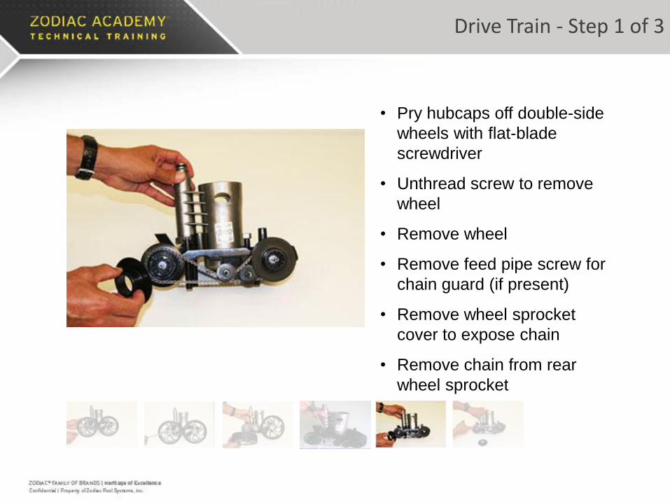
• Pry hubcaps off double-side
wheels with flat-blade
screwdriver
• Unthread screw to remove
wheel
• Remove wheel
• Remove feed pipe screw for
chain guard (if present)
• Remove wheel sprocket
cover to expose chain
• Remove chain from rear
wheel sprocket
Drive Train - Step 1 of 3

• Pry hubcaps off double-side
wheels with flat-blade
screwdriver
• Unthread screw to remove
wheel
• Remove wheel
• Remove feed pipe screw for
chain guard (if present)
• Remove wheel sprocket
cover to expose chain
• Remove chain from rear
wheel sprocket
Drive Train - Step 1 of 3

• Pry hubcaps off double-side
wheels with flat-blade
screwdriver
• Unthread screw to remove
wheel
• Remove wheel
• Remove feed pipe screw for
chain guard (if present)
• Remove wheel sprocket
cover to expose chain
• Remove chain from rear
wheel sprocket
Drive Train - Step 1 of 3

• Pry hubcaps off double-side
wheels with flat-blade
screwdriver
• Unthread screw to remove
wheel
• Remove wheel
• Remove feed pipe screw for
chain guard (if present)
• Remove wheel sprocket
cover to expose chain
• Remove chain from rear
wheel sprocket
Drive Train - Step 1 of 3
• Pry hubcaps off double-side
wheels with flat-blade
screwdriver
• Unthread screw to remove
wheel
• Remove wheel
• Remove feed pipe screw for
chain guard (if present)
• Remove wheel sprocket
cover to expose chain
• Remove chain from rear
wheel sprocket
Drive Train - Step 1 of 3

• Pry hubcaps off double-side
wheels with flat-blade
screwdriver
• Unthread screw to remove
wheel
• Remove wheel
• Remove feed pipe screw for
chain guard (if present)
• Remove wheel sprocket
cover to expose chain
• Remove chain from rear
wheel sprocket
Drive Train - Step 1 of 3

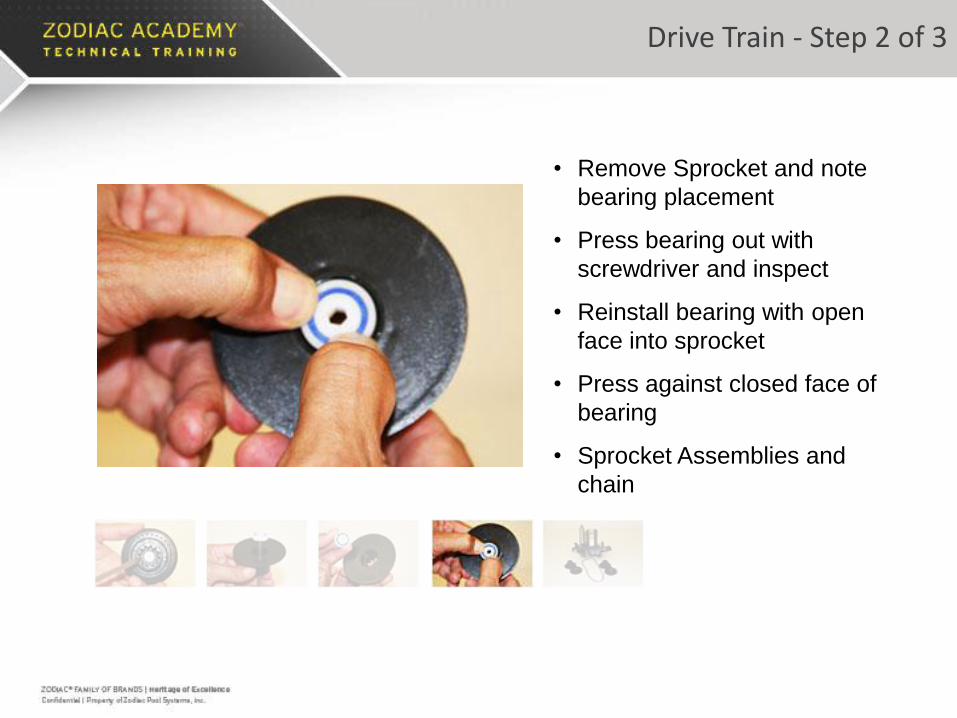
• Remove Sprocket and note
bearing placement
• Press bearing out with
screwdriver and inspect
• Reinstall bearing with open
face into sprocket
• Press against closed face of
bearing
• Sprocket Assemblies and
chain
Drive Train - Step 2 of 3

• Remove Sprocket and note
bearing placement
• Press bearing out with
screwdriver and inspect
• Reinstall bearing with open
face into sprocket
• Press against closed face of
bearing
• Sprocket Assemblies and
chain
Drive Train - Step 2 of 3

• Remove Sprocket and note
bearing placement
• Press bearing out with
screwdriver and inspect
• Reinstall bearing with open
face into sprocket
• Press against closed face of
bearing
• Sprocket Assemblies and
chain
Drive Train - Step 2 of 3
• Remove Sprocket and note
bearing placement
• Press bearing out with
screwdriver and inspect
• Reinstall bearing with open
face into sprocket
• Press against closed face of
bearing
• Sprocket Assemblies and
chain
Drive Train - Step 2 of 3

• Remove Sprocket and note
bearing placement
• Press bearing out with
screwdriver and inspect
• Reinstall bearing with open
face into sprocket
• Press against closed face of
bearing
• Sprocket Assemblies and
chain
Drive Train - Step 2 of 3

• Locate and remove wheel spacers
from 2 wheel side axles
• Locate and remove 2 screws at the
base of the feed pipe
• Remove the Vacuum Tube/Feed
pipe assembly
• Locate and remove the 2 screws
that attach each axle block to the
frame
• Frame assembly with Chain
Tensioner
Drive Train - Step 3 of 3

Drive Train - Step 3 of 3
• Locate and remove wheel spacers
from 2 wheel side axles
• Locate and remove 2 screws at the
base of the feed pipe
• Remove the Vacuum Tube/Feed
pipe assembly
• Locate and remove the 2 screws
that attach each axle block to the
frame
• Frame assembly with Chain
Tensioner

Drive Train - Step 3 of 3
• Locate and remove wheel spacers
from 2 wheel side axles
• Locate and remove 2 screws at the
base of the feed pipe
• Remove the Vacuum Tube/Feed
pipe assembly
• Locate and remove the 2 screws
that attach each axle block to the
frame
• Frame assembly with Chain
Tensioner

Drive Train - Step 3 of 3
• Locate and remove wheel spacers
from 2 wheel side axles
• Locate and remove 2 screws at the
base of the feed pipe
• Remove the Vacuum Tube/Feed
pipe assembly
• Locate and remove the 2 screws
that attach each axle block to the
frame
• Frame assembly with Chain
Tensioner

Drive Train - Step 3 of 3
• Locate and remove wheel spacers
from 2 wheel side axles
• Locate and remove 2 screws at the
base of the feed pipe
• Remove the Vacuum Tube/Feed
pipe assembly
• Locate and remove the 2 screws
that attach each axle block to the
frame
• Frame assembly with Chain
Tensioner

Drive Train - Step 3 of 3
• Locate and remove wheel spacers
from 2 wheel side axles
• Locate and remove 2 screws at the
base of the feed pipe
• Remove the Vacuum Tube/Feed
pipe assembly
• Locate and remove the 2 screws
that attach each axle block to the
frame
• Frame assembly with Chain
Tensioner

Product Breakdown

POLARIS®
3900 SPORT
REASSEMBLY
INSTRUCTIONS

• Assemble axle blocks with
star washers and screws
• Turn frame upside down and
install axle blocks to frame
• Drop gearbox into place with
brass inserts pointing up
• Attach gearbox with 4 screws
in pockets labeled “B”
• Install wheel spacers on
double side wheel axle blocks
Reassembly – Step 1 of 7

• Assemble axle blocks with
star washers and screws
• Turn frame upside down and
install axle blocks to frame
• Drop gearbox into place with
brass inserts pointing up
• Attach gearbox with 4 screws
in pockets labeled “B”
• Install wheel spacers on
double side wheel axle blocks
Brass
Inserts
Reassembly – Step 1 of 7

• Assemble axle blocks with
star washers and screws
• Turn frame upside down and
install axle blocks to frame
• Drop gearbox into place with
brass inserts pointing up
• Attach gearbox with 4 screws
in pockets labeled “B”
• Install wheel spacers on
double side wheel axle blocks
Reassembly – Step 1 of 7

• Attach Vacuum
Tube/Feedpipe Assembly to
frame with three screws
• Install Wheel sprockets on
double side axles
Reassembly – Step 2 of 7

• Attach Vacuum
Tube/Feedpipe Assembly to
frame with three screws
• Install Wheel sprockets on
double side axles
Reassembly – Step 1 of 7

• Attach Vacuum
Tube/Feedpipe Assembly to
frame with three screws
• Install Wheel sprockets on
double side axles
Reassembly – Step 1 of 7

• Wrap chain around front
axle sprocket and through
tensioner as shown
• Use the diagram on the
vacuum tube to assist with
wrap configuration
• Install the 2 sprockets
covers
• Install the chain guard on
the feed pipe screw.
Reassembly – Step 3 of 7

• Wrap chain around front
axle sprocket and through
tensioner as shown
• Use the diagram on the
vacuum tube to assist with
wrap configuration
• Install the 2 sprockets
covers
• Install the chain guard on
the feed pipe screw.
Reassembly – Step 3 of 7

• Wrap chain around front
axle sprocket and through
tensioner as shown
• Use the diagram on the
vacuum tube to assist with
wrap configuration
• Install the 2 sprockets
covers
• Install the chain guard on
the feed pipe screw.
Reassembly – Step 3 of 7

• Wrap chain around front
axle sprocket and through
tensioner as shown
• Use the diagram on the
vacuum tube to assist with
wrap configuration
• Install the 2 sprockets
covers
• Install the chain guard on
the feed pipe screw.
Reassembly – Step 3 of 7

• Wrap chain around front
axle sprocket and through
tensioner as shown
• Use the diagram on the
vacuum tube to assist with
wrap configuration
• Install the 2 sprockets
covers
• Install the chain guard on
the feed pipe screw.
Reassembly – Step 3 of 7

• Locate double side wheels
noting one bearing in the outer
cavity of each wheel
• Align wheels into sprockets and
attach with locking screw
• Attach single side wheel with
the same locking screw
Reassembly – Step 4 of 7

• Locate double side wheels
noting one bearing in the outer
cavity of each wheel
• Align wheels into sprockets and
attach with locking screw
• Attach single side wheel with
the same locking screw
Reassembly – Step 4 of 7

• Locate double side wheels
noting one bearing in the outer
cavity of each wheel
• Align wheels into sprockets and
attach with locking screw
• Attach single side wheel with
the same locking screw
Reassembly – Step 4 of 7

• Locate double side wheels
noting one bearing in the outer
cavity of each wheel
• Align wheels into sprockets and
attach with locking screw
• Attach single side wheel with
the same locking screw
Reassembly – Step 4 of 7

• Locate double side wheels
noting one bearing in the outer
cavity of each wheel
• Align wheels into sprockets and
attach with locking screw
• Attach single side wheel with
the same locking screw
Reassembly – Step 4 of 7
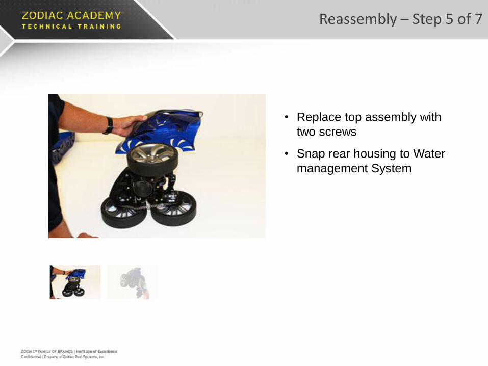
• Replace top assembly with
two screws
• Snap rear housing to Water
management System
Reassembly – Step 5 of 7

• Replace top assembly with
two screws
• Snap rear housing to Water
management System
Reassembly – Step 5 of 7
• Attach Water Management
System with 3 screws
• Slide bottom housing on
• Attached bottom housing with 3
screws
• Snap hub caps on all wheels
Reassembly – Step 6 of 7

• Attach Water Management
System with 3 screws
• Slide bottom housing on
• Attached bottom housing with 3
screws
• Snap hub caps on all wheels
Reassembly – Step 6 of 7
• Attach Water Management
System with 3 screws
• Slide bottom housing on
• Attached bottom housing with 3
screws
• Snap hub caps on all wheels
Reassembly – Step 6 of 7

• Attach Water Management
System with 3 screws
• Slide bottom housing on
• Attached bottom housing with 3
screws
• Snap hub caps on all wheels
Reassembly – Step 6 of 7

• Attach sweep hose – install
nut first then thread back on
to sweep hose
• Note the serial number
location under the canopy
• Press bag into vacuum tube
• Install quick disconnect
• Reassembly completed
Reassembly – Step 7 of 7

• Attach sweep hose – install
nut first then thread back on
to sweep hose
• Note the serial number
location under the canopy
• Press bag into vacuum tube
• Install quick disconnect
• Reassembly completed
Reassembly – Step 7 of 7

• Attach sweep hose – install
nut first then thread back on
to sweep hose
• Note the serial number
location under the canopy
• Press bag into vacuum tube
• Install quick disconnect
• Reassembly completed
Reassembly – Step 7 of 7

• Attach sweep hose – install
nut first then thread back on
to sweep hose
• Note the serial number
location under the canopy
• Press bag into vacuum tube
• Install quick disconnect
• Reassembly completed
Reassembly – Step 7 of 7

• Attach sweep hose – install
nut first then thread back on
to sweep hose
• Note the serial number
location under the canopy
• Press bag into vacuum tube
• Install quick disconnect
• Reassembly completed
Reassembly – Step 7 of 7

Thank You!