pm 8060 vitara - frank's hospital workshop€¦ · haemodynamic patient monitor pm 8060 vitara...
TRANSCRIPT
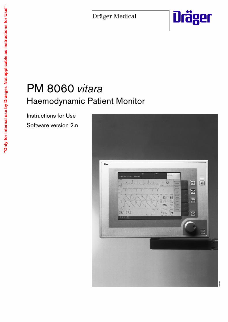
PM 8060 vitaraHaemodynamic Patient Monitor
Instructions for Use
Software version 2.n
2-89
3-96
DDräger Medical
"On
ly f
or
inte
rnal
use
by
Dra
eger
. No
t ap
plic
able
as
Inst
ruct
ion
s fo
r U
se!"

Working with these Instructions for Use
In the top header line – the subject...of the main chapter. The second line contains the title of the sub-chapter – foreasy reference and finding your way quickly about theInstructions for Use.
On the page body ...the Instructions for Use in combined text/graphical format. The information isexplained directly in terms of actions that teach the userhow to operate the machine by hands-on experience.
Left-hand column – the text ...contains explanations and instructs the user in theoperation of the product, with brief, unconfusinginstructions in ergonomic sequence.The bullets indicate separate actions, and, if severalactions are described for the same accompanyingillustration, the numbers provide clear cross-referencingbetween text and graphics and identify the sequence ofoperations.
Right-hand column – the illustrations ...provide the visual reference to the text and help locatethe various parts of the equipment. Parts mentioned inthe text are highlighted, and inessential details have beendeliberately omitted.Screen displays also guide the user and confirm correctperformance of the required operations.
Working with these Instructions for Use
2
Xxxxxxxxx
Xxxxxxxxxxxxxxxxxxxxxxxxxxxx:
Xxxxxxxxxx: Vxxxxxxxxx?
Xxxxxxxxxxxxx: Hxxxxxxx ?, Fxxxxxxx ?, Dxxxxxx ?
Xxxxxxxxx: Sxxxxxxxxxxxxx ?
Xxxxxxxxxx Xxxxxxx xxxxxxxxxxxxxxx
1 Xxxxxxxxxxx Xxxxxxxxxx xxxxx -
Xxxxxxxxxxxxx XXXXXXXXXX cccxxxxxxxxxxxxx xxxxx x
2 Xxxxxxxxxxxxxxxxxx xxxxxxxxx (X xxxxxxxxx).
Xxxxxxxxxxxxxxxxxxx
Xxxxxxxxxxxxxxx xxx Xxxxxxxxxxx xxxxxxxxx xxxxxxxx -
Xxxxxxxxxx - xxxxxx xxxxxxxxxxxx ! - xxx xxx Xxxxxxxxxx
xxxxxxxxxxxx xxxxx !
Xxxxxxxxxx xxxxxxxx xxxxxx xxx xxxxxxxxx Xxxxxxxxxx xxxxxx
xxx xxx Xxxxxxxxxxxxx:
– xxxx. –
(xxxxxxxx X xxxxxxxx Xxxxxxxxxxx)
Xxxxxx xxxxxxxxx xxxx xxxxxx Xxxxxxx xxxx Xxxxxxxxx.
Xxxxxx xxx Xxxxxxx xxx Xxxxxxxx xxxxxxxxxx.
O2-Xxxxxxx
Xxxxxxxxxxxxx xxx Xxxxxx xxxxxx xxxxxcxxx !
Xxxxxxxx xxx xxx Xxxxxxxxxxxxxxx xxx Xxxxxxxx xxxxxxxx -
xxxxxxxxxxxxxxxx xxxxxxxxxxxxx xxxxxxxxxxxx
Xxxxxxxxx xxxxxxxxx
Xxxxxxxxxxxx xxxxxxxx
3 Xxxx xx Xxxxx xxx xx Xxxxx xxxxxxxxxx xcxxxxxxxx - xxx xxx
Xxxxxxxcxx -
xxxxxx Xxxxxx Xxxxxxxxxxxxxxx xxxxx xxxxxxxxxxxxxx !
Xxxxxxxxxxxxx xx Xxxxxxxx xxxxx xxx xxxxxxxxxxxxx
4 Xxxxxxxx xxx xxx Xxxxxxxxxxx xcxx xxxxxxx xxxxxxxxx
(xxxxxxxxxxxx) -
Xxxxxxx Yxxxxxxxxx
1. EKG
1. EKG (Modul doppelter Höhe)
XYZ
10:3400:00
01-10-96
standard screen - adultAdvisory:Caution:Warning:
65pulse def. 0 ST + 0.05
122/ 89(100)
ARTiBP 1
4.5mean
CVP
99pulse 65
pulse 65
15min M (102)
SysmmHgDia
SpO2
122/ 89NiBP
36.8 37.2T1 T2 °C
iBP 2
auto setlimits
alarminfo
screenconfig.
para-meter
timerstart
limits
config.
1. ECGII
1mV
Pleth
ART
CVP
130
10
80
0
HR/Pulse (ECG)
Self-test
Technology for life
PM 8060 VitaraVersion 2.n 02-12-97
Modulseite (deutsch):36.8 37.2
T1 T2 °C
15min M (102)
SysmmHgDia
122/ 89NiBP
Sys
man 10:34 M (102)
man 10:35 M (11.1)
mmHgDia
122/ 89NiBP
117 M (102)
SysmmHgDia
122/ 89NiBP
SyskPaDia
15.2/ 9.3NiBP
99Puls 65
SpO2 %
(EKG)
1/min
mmHg mmHg
122/ 89(100)
ARTiBP 1
Puls 65
122/ 89(100)
AORTAiBP 1
Puls 65
mmHg
122/ 89(100)
A.PulmiBP 1
Puls 65
mmHg
122/ 89(100)
iBP ?iBP 1
Puls 65
65Pulsdef. 0 ST + 0.05
HR/Puls
21RR
mmHg mmHg
4.5mean
ZVDiBP 2 iBP 2
4.5mean
ICP
"On
ly f
or
inte
rnal
use
by
Dra
eger
. No
t ap
plic
able
as
Inst
ruct
ion
s fo
r U
se!"
Contents
3
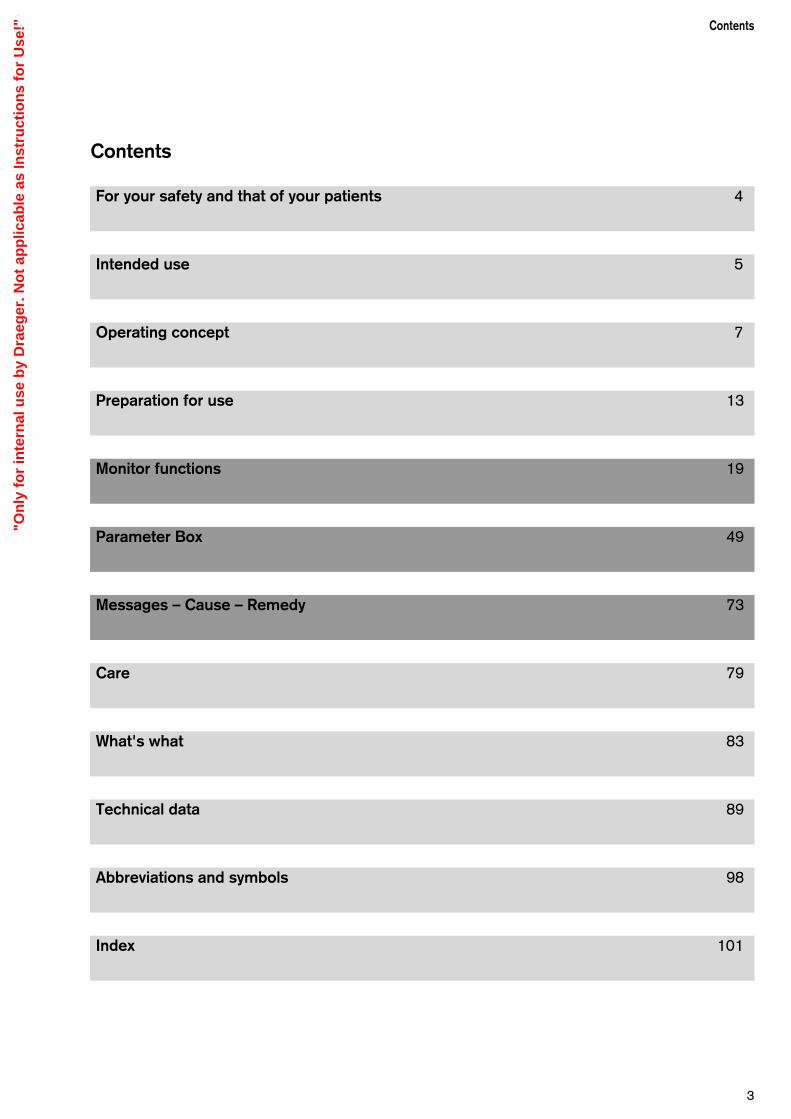
Contents
For your safety and that of your patients 4
Intended use 5
Operating concept 7
Preparation for use 13
Monitor functions 19
Parameter Box 49
Messages – Cause – Remedy 73
Care 79
What's what 83
Technical data 89
Abbreviations and symbols 98
Index 101
"On
ly f
or
inte
rnal
use
by
Dra
eger
. No
t ap
plic
able
as
Inst
ruct
ion
s fo
r U
se!"
For Your Safety and that of YourPatients
Strictly follow the Instructions for Use
Any use of the apparatus requires full understanding andstrict observation of these instructions.The apparatus is only to be used for purposes specifiedhere.
Maintenance
The apparatus must be inspected and serviced regularlyby trained service personnel at six monthly intervals. Repair and general overhaul of the apparatus may only becarried out by trained service personnel.We recommend that a service contract be obtained withDrägerService and that all repairs also be carried out bythem.Only authentic Dräger spare parts may be used for main-tenance. Observe chapter "Maintenance Intervals".
Accessories
Do not use accessory parts other than those in the orderlist.
Not for use in areas of explosion hazard
This apparatus is neither approved nor certified for use inareas where combustible or explosive gas mixtures arelikely to occur.
Safe connection with other electrical equipment
Electrical connections to equipment which is not listed inthese Instructions for Use should only be made followingconsultations with the respective manufacturers or anexpert.
Liability for proper function or damage
The liability for the proper function of the apparatus isirrevocably transferred to the owner or operator to theextent that the apparatus is serviced or repaired bypersonnel not employed or authorized by DrägerServiceor if the apparatus is used in a manner not conforming toits intended use.Dräger cannot be held responsible for damage causedby non-compliance with the recommendations givenabove.The warranty and liability provisions of the terms of saleand delivery of Dräger are likewise not modified by therecommendations given above.
Dräger Medical AG & Co. KGaA
For your safety and that of your patients
4
"On
ly f
or
inte
rnal
use
by
Dra
eger
. No
t ap
plic
able
as
Inst
ruct
ion
s fo
r U
se!"

Contents
Intended use..............................................................................................6
5
Intended useContents
Intended use
"On
ly f
or
inte
rnal
use
by
Dra
eger
. No
t ap
plic
able
as
Inst
ruct
ion
s fo
r U
se!"
Intended use
Haemodynamic Patient Monitor PM 8060 vitara
When connected to the parameter box, the essentialhaemodynamic parameters are displayed together withtheir monitoring features:
– The ECG curve with heart rate and ST segmentanalysis.
– Two channels for invasively measured blood pressure(iBP), with the pressure values for systolic, diastolicand mean pressure and the pressure curve.
– The measured values for the non-invasively measuredblood pressure (NiBP) with the pressure values forsystolic, diastolic and mean pressure.
– Two channels for body temperature.
– The functional O2 saturation (SpO2) with the pulserate.
– The plethysmogram.
– The respirogram.
– When connected to an anaesthetic workstation, datafrom an airway monitor can also be displayed, but inthis case airway alarms are not transferred to thePM 8060 vitara.
Precautions for useFire risk. Use only non-flammable anaesthetic agentsconforming to EN 740.
Any add-on electrical equipment must be earthed bymeans of an equipotential bonding conductorconnected to the base unit.
Electromagnetic fields that exceed the value specifiedin EN60601-1-2 may impair the operation of theapparatus (for example during nuclear spin tomography -MRT, NMR and NMI).
Do not use mobile phones within a distance of 10 metres from the machine.Mobile phones can cause interference to electrical andelectronic medical appliances, thereby putting patients atrisk.*
Use the workstation under the supervision of qualifiedmedical personnel, so that assistance can be providedimmediately in the event of any malfunction!
* Dräger medical appliances comply with the interference immunityrequirements of the specific standards for the products or EN 60601-1-2 (IEC 601-1-2). However, depending on the designof the mobile phone and situation of use, field strengths may occurin the immediate environment of a mobile phone that exceed thevalues of the standards quoted and therefore cause interference.
Intended use
6
"On
ly f
or
inte
rnal
use
by
Dra
eger
. No
t ap
plic
able
as
Inst
ruct
ion
s fo
r U
se!"
Contents
User interface........................................................................................... 8Keys with dedicated function......................................................................8Keys with variable function......................................................................... 8Rotary control.............................................................................................9Indicator lamps.........................................................................................10Structure of the screen display................................................................. 10Menu structure......................................................................................... 10Screen saver............................................................................................11Colour concept........................................................................................ 11The various screen displays......................................................................11
Operating conceptContents
7
Operating concept
"On
ly f
or
inte
rnal
use
by
Dra
eger
. No
t ap
plic
able
as
Inst
ruct
ion
s fo
r U
se!"

User interface
Keys with dedicated function (Hardkeys)
The right-hand side is reserved for operating elements,the left-hand side for displays.
G This key is used to deactivate the alarm tone fortwo minutes. The alarm is reactivated by pressingthe key again. The yellow LED in the key lights upwhile alarms are suspended.
Any new messages are signalled once by theappropriate tone sequence.
E This key switches the monitor from standby tomeasuring mode and vice versa.
The dark area contains four keys that act directly on thescreen contents:
S This key is used to select the desired screen(standard screen, trend screen and list screen).
Q This key is always used to call up the last standardscreen used.
X This key is used to »freeze« the haemodynamiccurves on the screen so that they can be viewed inmore detail.
U This key is used to generate a manual entry in thelist screen.
Keys with variable function (Softkeys)An unlabelled membrane keypad is positioned next to theright-hand edge of the screen.
The function of each of these keys at any one time issoftware-driven and is displayed in the correspondingposition on the screen.
The screen only displays the keys that can be activated atthat moment.
Operating conceptUser interface
8
D
1-2--
Stop
D
1-2--
Stop
0022
9094
0032
9094
"On
ly f
or
inte
rnal
use
by
Dra
eger
. No
t ap
plic
able
as
Inst
ruct
ion
s fo
r U
se!"

Rotary controlA single "turn-and-push" control is used to select andconfirm settings.
Turn to select:Turning the rotary control moves a cursor frame acrossthe screen or changes a numeric value.
Press to set: When the rotary control is pressed, the value selected byturning the control is accepted as the valid parameter, ora process is started or stopped.
Example: To adjust the volume of the audible alarm
1 Call up the configuration menu from standby modeby pressing the »config« softkey.
A menu of default settings is displayed.
Select = turn the rotary control.
Move the cursor frame to the »acoustic« field.
Confirm = press the rotary control.
2 The selected option »acoustic« is highlighted ininverse video (dark type on light background – see colour concept).
The cursor frame is positioned over the arrowsymboll ( z ) in the open »acoustic« field.
3 This menu is used to:
– set the volume of the alarm and of the pulse tone,
– select between a plain pulse tone and a pulse toneof variable frequency modulated by the degree ofoxygen saturation (SpO2).
– select the tone system (Dräger or ISO standard).
Turn the rotary control = move the cursor frame intothed »alarm sound« field.
Confirm = press the rotary control.
The confirmed selection »alarm sound« is high-lighted in inverse video (dark on light). The tone isplayed back at the selected volume.
The dashed selection window now contains volumelevels from »1« (soft) to »9« (loud).
The original value (here: »5«) is set against anorange background.
To set a new value = turn the rotary control.
Move the cursor to the desired volume. The tone isplayed back at the selected volume.
Confirm = press the rotary control.
The new value is displayed against an orangebackground. The cursor-frame returns to the arrowsymbol ( z ).
Press the rotary control again (if necessary severaltimes). The cursor moves back one menu level at atime, in each case to the arrow symbol ( z ), untilyou exit the configuration menu.
9
Operating conceptUser interface
Standby/Configuration
10:3400:00
01-10-96Alarm sound and pulse tone configuration menu. Please confirm !
Default values
mode adult neon.
alarm limits
parameter
screen
acoustic
list entry
transport
RS 232 (Medibus)
RS 232 (Printer)
basic config.
alarm sound 1 2 3 4 5 6 7 8 9
pulse tone 0 1 2 3 4 5 6 7 8 9
pulse tone ECG Pleth.SpO2 modulated
tone sequence DRÄGER Euro-Standard
alarms inactive !
deletetrend
config.
Switch on with
Standby
Data ManagerSW-Version 2.n
02-12-97
ParameterboxSW-Version 2.n
PM 8060 Vitara
E
1
2
3
0092
9094
0102
9094
0112
9094
"On
ly f
or
inte
rnal
use
by
Dra
eger
. No
t ap
plic
able
as
Inst
ruct
ion
s fo
r U
se!"

Indicator lamps
Two bar-shaped indicator lamps are located above theG key: these lamps continue to indicate the alarmstates even when the acoustic alarm is suspended:
Red (upper) lamp, flashing: Warning !!!Yellow (lower) lamp, flashing: Caution !!Yellow lamp, constant: Advisory !
Structure of the screen display
The screen is made up of grids in which the individualtraces and blocks of measured values (»modules«) canbe defined as required.
The fields for date/time, equipment status, warning,caution or advisory messages, the screen keys (softkeys)and the user advisory field are always located in the sameplace in all screens.
Menu structure
The hierarchy and sequence of menu levels is made clear by their staggered arrangement across the screen.The active menu is always green with a yellow cursor.Previous menu levels are grey with a black cursor.
The fields shown against an orange background indicatethe current configuration. The procedure for opening andclosing menus is always the same.
It is always possible to return directly to the standardscreen by pressing the Q key.
Operating concept User interface
10
Standby/Configuration alarms inactive !
10:3400:00
01-10-96
Default values
mode adult neon.
alarm limits
parameter
screen
acoustic
list entry
transport
RS 232 (Medibus)
RS 232 (Printer)
basic config.
ECG
NiBP
iBP locations
iBP channels
SpO2 / Pleth
Resp.
Select a menu position. Please confirm !Change the settings. Please confirm again !
ECG
function on off
numberof leads 3 5
ST-segmentanalysis on off
pulse deficit on offindication
pacemaker on off
filter on off
amplitude 2
1.ECG2.ECG 3.ECG
derivation I IIIII
State Warning / Caution / Advisory
Modules (Curves / Graphs)
Date / Time User advisory field
D
1-2--
Stop
0042
9094
0122
9094
0132
9094
"On
ly f
or
inte
rnal
use
by
Dra
eger
. No
t ap
plic
able
as
Inst
ruct
ion
s fo
r U
se!"

Screen saver
If none of the controls or keys on the Monitor is operatedfor about 5 minutes while in »Standby« mode, the screenswitches to a screen saver program to prevent screenburn-in. The yellow LED in the Standby key lights up, anda Dräger logo ( D) appears at different positions onthe screen.
The screen display is restored immediately any useroperation is detected.
Colour concept
Certain colours are used recurrently with the samestandard meaning when operating the device:
Screen element: Display colour:
Active menu level .................... Cyan
Non-active menu level ............. Grey
Cursor .................................... Yellow frame
Selected menu item ................ Inverse (white on black)
Selected alternative................. Orange background
Alarm messages are displayed in clearly distinct fieldsaccording to the urgency of the message:
1 Warning Symbol »!!!« Text on red field2 Caution Symbol »!!« Text on yellow field3 Advisory Symbol »!« Text on white field
The colours of the individual measurement parametersand displays and the choice of bright or dark backgroundcan be freely configured by the user (see page 30).
The various screen displays
4 The other screen pages are called up by pressing
S.
A selection menu is then displayed for the followingalternative screen displays:
– Standard screen 1,
– Standard screen 2,
– List screen and
– Trend screen.
11
Operating conceptScreen displays
D
Stop
1-2-- 4
0062
9094
10:3400:00
01-10-96 The limit indicated has been violated. Please select a new value and confirm !
standard screen - adultAdvisory:Caution:Warning:TEMP2 CALIB !TEMP1 !!SPO2 !!!
1. ECGII
1mV
ART
CVP
Pleth
65pulse def. 0 ST + 0.05
HR/Pulse (ECG)
122/ 89(100)
ARTiBP 1
4.5mean
CVP
94pulse 65
pulse 65
15min M (102)
SysmmHgDia
SpO2
122/ 89NiBP
36.8 37.2T1 T2 °C
iBP 2
160
20
0
0
auto setlimits
alarminfo
timerstart
limitsHR 72 50 120
Puls 72 50 120
NiBP
sys -- 80 160
SpO2 92 94 --
ST 0.00 ± 0.10
T1 37.5 -- --
T2 32.2 -- --
RR -- 5 25
iBP1
sys 122 80 160
iBP2
Mean 4.5 80 160
0542
9094
1 2 3
"On
ly f
or
inte
rnal
use
by
Dra
eger
. No
t ap
plic
able
as
Inst
ruct
ion
s fo
r U
se!"

Standard screen (1 or 2)containing the configured graph and measured valuefields.
List screencontaining all measured values and alarms; therebymaking it easier to complete the anaesthesia record. This list can also be printed out to a connected printer(optional).
Trend screenfor displaying the trend curves of the measured valuesover time.
12
11:3400:00
01-10-96
list screen - adultAdvisory:Caution:Warning:
intubation
start ofsurgery
positionchange
extuba-tion
start ofanaesthesia
end ofsurgery
event
1. ECGII
1mV
65pulse def. 0 ST + 0.05
Manual list entry by
time
10:55 interval 2 01-10-9610:55 IND-210:55 11:0011:0511:08 intubation11:1011:1311:1511:20 interval 1 01-10-9611:20 OP-2 11:20 11:25 11:3011:32 start of surgery
HR/Pulse1/min
6467
636263
6362
NiBP mmHgSys/M/Dia
120/100/90123/103/88
120/100/90123/103/88128/107/93
120/100/90122/102/89
SpO2%
90 97
96 90 97
95 97
CO2Vol. %Fet
3537
313433
3537
PAW mbar peak/PEEP
32/3 31/3
33/3 31/3 30/3
32/3 31/3
Warning
SPO2
SPO2
!!!
!!!
MVL/min
6.4 6.3
6.2 6.1 6.0
6.4 6.3
Cpatml/mbar
1212
121212
1212
O2Vol. %Fi
2131
323133
3031
anaesth.agentFi
ENF1.41.4 1.21.21.1
ISO1.41.4
temp°CT1
36.836.9
36.736.836.9
36.836.9
config. list entry next page preceding page
HR/Pulse (ECG)
10:3400:00
01-10-96 Select a trend sector and magnify by confirming !
NiBP SpO2
HR/RRIBP 1200
100
0
100
60
80
200
100
0
11:00 12:00 13:00
Sys
MDia
Sys
MDia
200
100
0
11:00 12:00 13:00
1. ECG II
1mV
fulltrend
config.
trend screen - adultAdvisory:Caution:Warning:
65pulse def. 0 ST + 0.05
HR/Pulse (ECG)
0152
9094
0162
094
10:3400:00
01-10-96
standard screen - adultAdvisory:Caution:Warning:
65pulse def. 0 ST + 0.05
122/ 89(100)
ARTiBP 1
4.5mean
CVP
99pulse 65
pulse 65
15min M (102)
SysmmHgDia
SpO2
122/ 89NiBP
36.8 37.2T1 T2 °C
iBP 2
auto setlimits
alarminfo
screenconfig.
para-meter
timerstart
limits
config.
1. ECGII
1mV
Pleth
ART
CVP
130
10
80
0
HR/Pulse (ECG)
0142
9094
"On
ly f
or
inte
rnal
use
by
Dra
eger
. No
t ap
plic
able
as
Inst
ruct
ion
s fo
r U
se!"

Contents
Connecting the System ......................................................................... 14Connecting the power supply .................................................................. 14Connecting external devices ....................................................................14
Switching the monitor on and off .......................................................... 18
13
Preparation for useContents
Preparation for use
"On
ly f
or
inte
rnal
use
by
Dra
eger
. No
t ap
plic
able
as
Inst
ruct
ion
s fo
r U
se!"

Connecting the System
Connectingthe power supply:
When used in combination with an anaestheticmachine »Julian«:
1 Connect the CAN port (marked »CAN 1«) at the backof the screen to the CAN port on the back of theanaesthetic unit (port marked »CAN 1«).
When used as stand-alone Monitor or with Dräger-»Cato«:
1 Connect the CAN port (marked »CAN 1«) at the backof the screen to the Vitara power adapter.
Plug the power cord from the Vitara power adapterinto a 230 V mains socket. With anaesthetic units, thepower is supplied via a socket that is switched on andoff by the system master switch.
2 »CAN 2« is designed for add-on units.
3 For intracranial and intracardial operations,equipotential bonding must be ensured by connectinga grounding cable from the ground stud on the backof the screen (marked P ) to the ground stud in theoperating theatre!
Connecting external devices Interface configuration, see page 34.
Via the RS 232 printer interface:
4 Using a printer data cable (serial interface orconverter for the parallel interface)
Secure the device connectors by tightening thescrews provided!
Via the Dräger RS 232 MEDIBUS interface:
5 Using a data cable for connecting a Medibus device(e.g. PM 8050 Monitor, »Julian« AnaestheticWorkstation or a PC).
Secure the device connectors by tightening thescrews provided!
Via the RGB interface:
6 Using the monitor cable to connect an external RGBscreen (VGA or SVGA, Multisync.).
Secure the device connectors by tightening thescrews provided!
Preparation for use Connecting the System
14
RGB RS 232 C RS 232 C CAN 2 CAN 1
m P
4 56 12 3
0182
9094
"On
ly f
or
inte
rnal
use
by
Dra
eger
. No
t ap
plic
able
as
Inst
ruct
ion
s fo
r U
se!"

15
Preparation for use Connecting the System
PM 8060 vitara to »Julian«
Julian CAN 1/2...................to.....Vitara CAN 1
Julian CAN 1/2...................to.....Parameter box holder
Julian COM .......................to.....Vitara RS 232 C
Printer................................to.....Vitara RS 232 C wThe authorised cable types are listed in the Accessorieslist.
PM 8060-vitara with external power adapteras stand-alone monitor or connected to»Cato«:
Power adapter CAN1/2......to.....Vitara CAN 1
Power adapter CAN1/2......to.....Parameter box holder
Airway monitor ...................to.....Vitara RS 232 C
Printer................................to.....Vitara RS 232 C wThe authorised cable types are listed in the Accessorieslist.
Never connect a CAN connector to an RS 232 Cconnector: especially in PCs, a wrong connection ofthis kind can damage the RS 232 C interface.
COM 3
COM 2CAN 1
CAN 2
COM 1
m P
0192
9094
Medibus-Device
Printer
Vitara
Power Supply Parameterbox
option
option
0172
9094
"On
ly f
or
inte
rnal
use
by
Dra
eger
. No
t ap
plic
able
as
Inst
ruct
ion
s fo
r U
se!"

Fitting the PM 8060 vitara to the swivel armof a Dräger Anaesthetic Unit
Push the arm on to the rail and fix with two screws.
1 The arm's resistance to movement can be adjusted atthe hinge (Allen screw - A/F 6 mm).
2 Screw the PM 8060 vitara securely to the arm. Ifnecessary, fix with thread-locking compound (Allenscrew - A/F 12 mm).
Fitting the PM 8060 vitara to the swivel armof a standard rail
Check the load-bearing capacity of the rail.The weight of the PM 8060 vitara complete withparameter box is approx. 5 kg.
3 Screw the PM 8060 vitara securely to the arm. If necessary, fix with thread-locking compound (Allen screw - A/F 12 mm).
4 Place the arm on the rail and fix with the rail clamp.
Also fix the power adapter to the rail.
PM 8060 vitara stand-alone on pedestal
5 Screw the PM 8060 vitara securely to the pedestal(Allen screw - A/F 12 mm) and stand on a suitablystrong, horizontal and non-slip surface.
Turning and tilting
You can adjust the viewing angle of the PM 8060 vitaraand adapt it to the ergonomic requirements of yourworkplace.
6 The tilt resistance can be adjusted with two cross-slottet screws.
7 The swivel resistance can be adjusted by the screwon the inside of the fixing column (Allen screw - A/F 5 mm).
Preparation for useConnecting the System
16
D
D
1-2--
Stop
D
1-2--
Stop
D
1-2--
Stop
12
3
4
5
6
7
0202
9094
0212
9094
0222
9094
0232
9094
"On
ly f
or
inte
rnal
use
by
Dra
eger
. No
t ap
plic
able
as
Inst
ruct
ion
s fo
r U
se!"

17
Preparation for useConnecting the System
Fitting the parameter box
The parameter box can be operated either in its blueholder or in the slot-in housing.
The slot-in housing can be installed in an anaestheticsystem (e.g. Julian or Cato) by Dräger Service.
The blue holder can be attached by the user to astandard rail (10 x 25 millimetres) in the work area.
With the blue holder, the parameter box can be pivotedup and down. In the slot-in housing, its position is fixed.
In both cases, the synchronisation output for anexternal defibrillator is accessible from the back ofthe machine!
Holder for operating table:
Alternatively, the "Op. Table" parameter box holder canbe used. This holder is especially suitable for fixing closeto the patient. It can remain on the operating table or bedwhen transporting the patient. The parameter box isconnected to the PM 8060 vitara by means of the quick-release cable and is mounted securely in the housing.
This system is not compatible with the holders withclip-in mechanism.
Slot-in housing:
Push the parameter box as far as it will go into theslot-in housing. The parameter box must lock intoposition, thereby connecting up its electricalconnections.
To remove the parameter box, pull the blue handle onthe parameter box to release the locking mechanism.The parameter box can then be pulled out of the slot-in housing.
Blue holder:
Fix the blue holder in a suitable position.
Connect the holder to the power supply (i.e. thepower adapter in the stand-alone version or the backof the Julian or Physio Flex) using the cable supplied.
Hang the parameter box onto the holder from above.The plug connector must engage.
To remove the parameter box, pull the blue handle ofthe box. This releases the box so that it can beremoved from the blue holder.
1 Defibrillator connection.
D
D
1-2--
Stop
1
0242
9094
0252
9094
0262
9094
1
0982
9094
"On
ly f
or
inte
rnal
use
by
Dra
eger
. No
t ap
plic
able
as
Inst
ruct
ion
s fo
r U
se!"
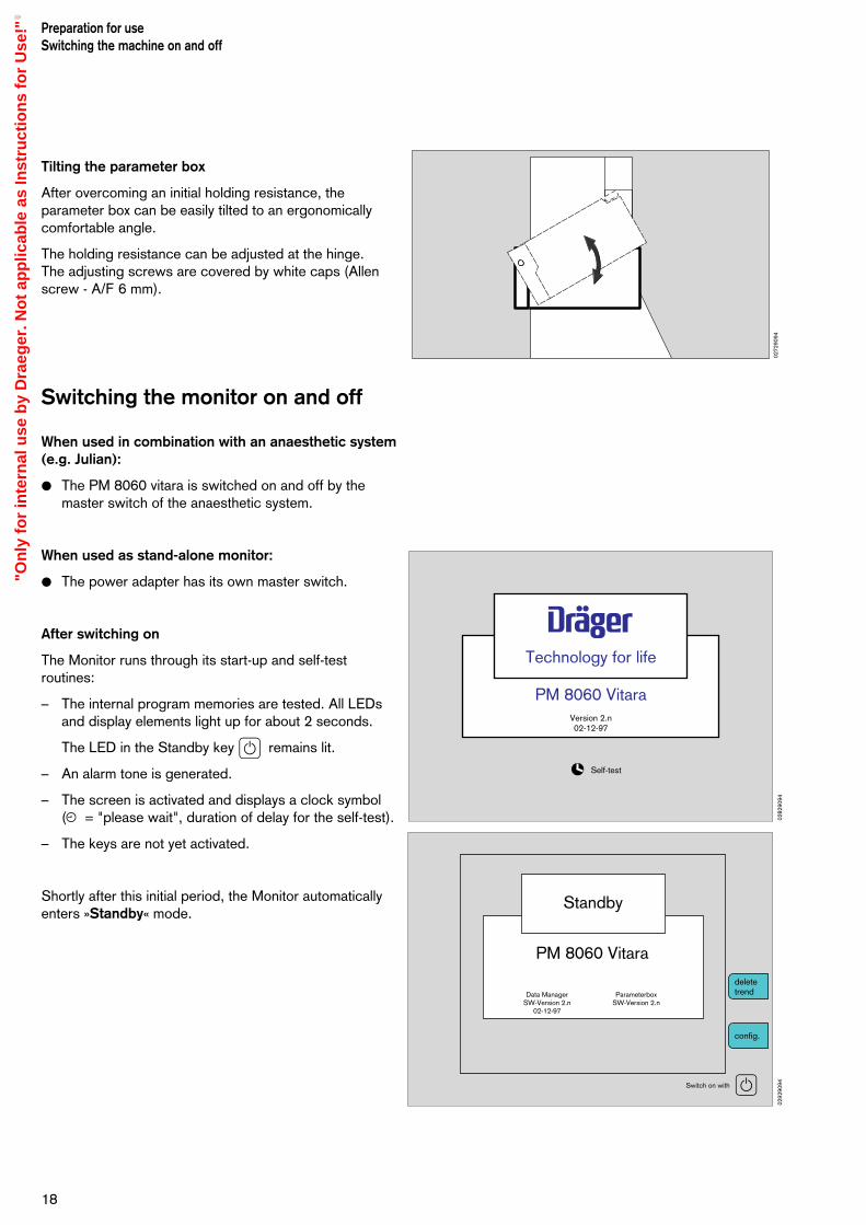
Tilting the parameter box
After overcoming an initial holding resistance, theparameter box can be easily tilted to an ergonomicallycomfortable angle.
The holding resistance can be adjusted at the hinge. The adjusting screws are covered by white caps (Allenscrew - A/F 6 mm).
Switching the monitor on and off
When used in combination with an anaesthetic system(e.g. Julian):
The PM 8060 vitara is switched on and off by themaster switch of the anaesthetic system.
When used as stand-alone monitor:
The power adapter has its own master switch.
After switching on
The Monitor runs through its start-up and self-testroutines:
– The internal program memories are tested. All LEDsand display elements light up for about 2 seconds.
The LED in the Standby key E remains lit.
– An alarm tone is generated.
– The screen is activated and displays a clock symbol(u = "please wait", duration of delay for the self-test).
– The keys are not yet activated.
Shortly after this initial period, the Monitor automaticallyenters »Standby« mode.
Preparation for useSwitching the machine on and off
18
Self-test
Technology for life
PM 8060 VitaraVersion 2.n 02-12-97
deletetrend
config.
Switch on with
Standby
Data ManagerSW-Version 2.n
02-12-97
ParameterboxSW-Version 2.n
PM 8060 Vitara
E
0282
9094
0292
9094
0272
9094
"On
ly f
or
inte
rnal
use
by
Dra
eger
. No
t ap
plic
able
as
Inst
ruct
ion
s fo
r U
se!"

Contents
Configuring the screen .......................................................................... 20Mode....................................................................................................... 22Alarm limits ..............................................................................................23Parameters...............................................................................................23Configuring the standard screen with modules ........................................ 27Configuring the screen colours ................................................................30Acoustic ..................................................................................................31List entry ................................................................................................. 32Transport function.................................................................................... 32RS 232 MEDIBUS................................................................................... 34RS 232 Printer ........................................................................................ 34Basic configuration...................................................................................35
Screen functions during operation ........................................................ 35Starting up the screen ............................................................................. 35Standard screen ......................................................................................37List screen .............................................................................................. 37Trend screen with zoom function ............................................................. 39Alarm limits ..............................................................................................40Autosetting the patient alarms ..................................................................41Alarm information .................................................................................... 42Configuring the screen structure in operation ...........................................42Parameters ..............................................................................................42Timer .......................................................................................................43Configuration .......................................................................................... 43
Alarm concept ........................................................................................45Alarm priority ...........................................................................................45
19
Screen functionsContents
Screen Functions
"On
ly f
or
inte
rnal
use
by
Dra
eger
. No
t ap
plic
able
as
Inst
ruct
ion
s fo
r U
se!"

0302
9094
0102
9094
Configuring the screen
Basic configuration in standby mode:
The basic configuration is protected by a password andcan only be modified in standby mode. This configurationis reactivated whenever the Monitor is started (i.e.switched on or operated from standby mode). It can alsobe reactivated by selecting »Call standard« duringoperation.
Temporary configuration during operation:
The screen settings entered during operation remainactive until the screen is next switched off.
The alarm limits set during operation only remain activeuntil the screen is next switched to standby mode.
In both cases, after switching off, the password-protected basic configuration is reactivated. Thisconfiguration can also be activated at any time byselecting »Call standard«.
If the screen has been blacked out by the screen-saverfunction, it will be reactivated as soon as any activity isdetected on the machine!
The »Standby« screen contains two screen keys(softkeys) for calling up menus:
1 Delete trend; e.g. for a new patient:
The »Standby« screen contains two screen keys(softkeys) for calling up menus for
– deleting the trend and list memory
– configuring the screen.
The trend memory and list are both cleared at the sametime. If a parameter box is connected, the data in theparameter box will also be deleted!
Press the »delete trend« softkey. The system asks you again to confirm you are sureyou want to delete the trend.
Press the »delete« key to confirm.
If you press »do not delete«, the original screen willbe restored unchanged.
2 Calling up the standby configuration menu
Press the »config« softkey to obtain the configurationmenu.
Configurations set in »standby« mode remain activewhenever the machine is switched on again.
By contrast, configurations entered during operation areonly valid until the machine is next switched off (alarmlimits remain valid until the next »Standby«).
Screen functionsConfiguring the screen
20
deletetrend
config.
Switch on with E
Standby
Data ManagerSW-Version 2.n
02-12-97
ParameterboxSW-Version 2.n
PM 8060 Vitara
deletetrend
config.
Switch on with
Standby
Data ManagerSW-Version 2.n
02-12-97
ParameterboxSW-Version 2.n
PM 8060 Vitara
E
1
2
"On
ly f
or
inte
rnal
use
by
Dra
eger
. No
t ap
plic
able
as
Inst
ruct
ion
s fo
r U
se!"

The screen illustrated opposite is displayed:
Turn the rotary control until the cursor frame ispositioned over »default values«.
Press the rotary control.
Changing default values
The password-protected default settings are activatedwhenever the machine is switched on. Before thesesettings can be changed, the correct password must beentered:
Entering the password:
The password consists of four digits. The numbersare selected one-by-one from the number bar byturning the rotary control and pressing to confirm ineach case.
After you have confirmed the fourth correct digit, you willbe allowed to access the "default values" pull-downmenu.
The menu for configuring the default values and settingsis displayed:
mode Switches over between adult andneonatal mode (toggle).
alarm limits Configure the defaults for adult orneonatal alarm limits.
parameters Default settings for thehaemodynamic parameters.
screen Configures the various screens.
acoustic Sets the volume and type of tonesequence.
transport Defines the data exchange betweenparameter box and system monitorduring patient transfer.
RS 232 (MEDIBUS) Sets the interface parameters
RS 232 (Printer) Configures the printer interface orthe second Medibus interface.
basic config. Date time and language selectionand location of the machine.
21
Screen functionsConfiguring the screen
Standby/Configuration alarms inactive !
10:3400:00
01-10-96Check system configuration. Please confirm !
Default values
mode adult neon.
alarm limits
parameter
screen
acoustic
list entry
transport
RS 232 (Medibus)
RS 232 (Printer)
basic config.
Standby/Configuration alarms inactive !
10:3400:00
01-10-96
Default values
These default settings are passwordprotected.The default settings are activeon start-up.
To change the default settingsenter the password:
0 1 2 3 4 5 6 7 8 9
0332
9094
0322
9094
Standby/Configuration alarms inactive !
10:3400:00
01-10-96Check system configuration. Please confirm !
Default values
mode adult neon.
alarm limits
parameter
screen
acoustic
list entry
transport
RS 232 (Medibus)
RS 232 (Printer)
basic config.
0332
9094
"On
ly f
or
inte
rnal
use
by
Dra
eger
. No
t ap
plic
able
as
Inst
ruct
ion
s fo
r U
se!"
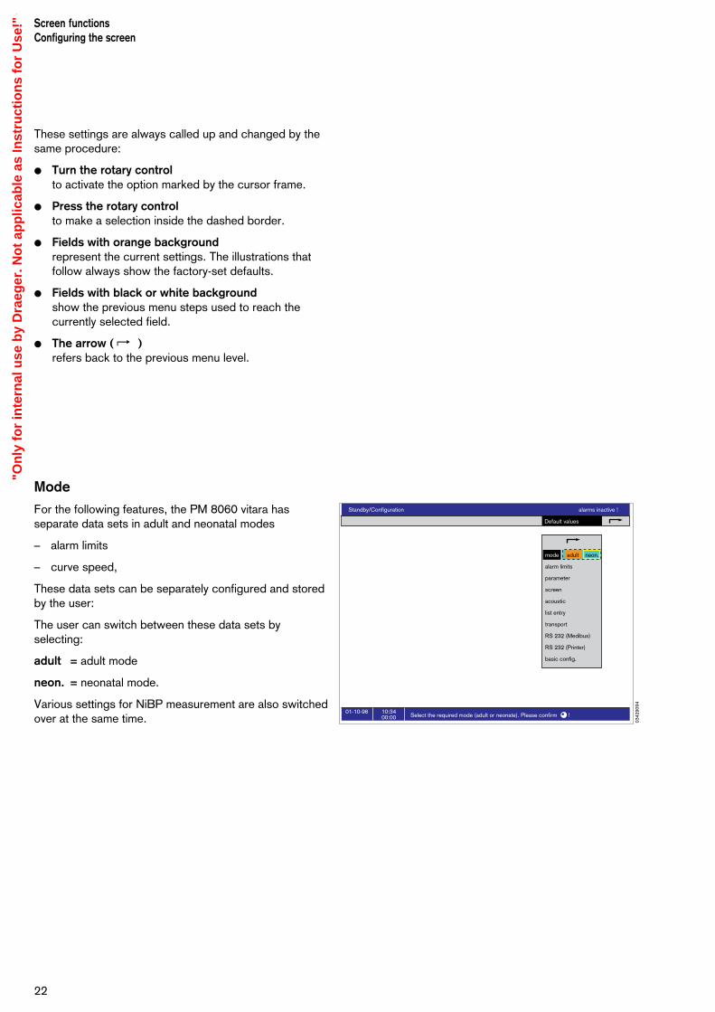
These settings are always called up and changed by thesame procedure:
Turn the rotary controlto activate the option marked by the cursor frame.
Press the rotary controlto make a selection inside the dashed border.
Fields with orange backgroundrepresent the current settings. The illustrations thatfollow always show the factory-set defaults.
Fields with black or white backgroundshow the previous menu steps used to reach thecurrently selected field.
The arrow ( z )refers back to the previous menu level.
Mode
For the following features, the PM 8060 vitara hasseparate data sets in adult and neonatal modes
– alarm limits
– curve speed,
These data sets can be separately configured and storedby the user:
The user can switch between these data sets byselecting:
adult = adult mode
neon. = neonatal mode.
Various settings for NiBP measurement are also switchedover at the same time.
Screen functionsConfiguring the screen
22
Standby/Configuration alarms inactive !
10:3400:00
01-10-96Select the required mode (adult or neonate). Please confirm !
Default values
mode adult neon.
alarm limits
parameter
screen
acoustic
list entry
transport
RS 232 (Medibus)
RS 232 (Printer)
basic config.
0342
9094
"On
ly f
or
inte
rnal
use
by
Dra
eger
. No
t ap
plic
able
as
Inst
ruct
ion
s fo
r U
se!"

Alarm limits
This menu defines:
– the default alarm limits for the two different operatingmodes (adults and neonates).
These alarm limits are automatically active after
– switching on the PM 8060 vitara
– leaving »Standby« mode
– selecting »default« under »Alarms«.
If the adult/neonate (adult/neon.) mode is changed later,the alarm limits preset for the relevant mode will remainvalid.
From this menu, the familiar procedure of »selecting«(turning the rotary control) and »confirming« (pressingthe rotary control) can be used to open the following sub-menus
– iBP
– ECG / SpO2 / NiBP / Temp / ST / RR
complete with the corresponding settings for the upperand lower alarm limits.
Two dashes ( – – ) in the table mean that this alarm limitis inactive and not monitored. It can be activated by turning the rotary control beyond the maximum orminimum value possible and confirming it.
Parameters
The settings for the following parameters are defined inthis menu:
ECG Electrocardiogram
NiBP Non-invasive blood pressure
iBP measuring site Preconfiguration for measuringsites
iBP channels Preconfiguration for channels
SpO2/Pleth Pulsoximetry/plethysmogram
Resp Respiration
23
Screen functionsConfiguring the screen
Standby/Configuration alarms inactive !
10:3400:00
01-10-96Standard alarm limits configuration menu. Please confirm !
Default values
mode adult neon.
alarm limits
parameter
screen
acoustic
list entry
transport
RS 232 (Medibus)
RS 232 (Printer)
basic config.
standard adult
standard neon.
Standby/Configuration alarms inactive !
10:3400:00
01-10-96Standard alarm limits configuration menu. Please confirm !
Default values
mode adult neon.
alarm limits
parameter
screen
acoustic
list entry
transport
RS 232 (Medibus)
RS 232 (Printer)
basic config.
iBP
standard - adult
ECG/SpO2/NiBP/Temp/
Aorta sys
dia
A.Pulm sys
mean
dia
CVP mean
ICP mean
? sys
mean dia
HR/Pulse
Pulsedef.
SpO2
NiBP/ART sys
dia
RR
T1
T2
ST
--
120 50
160 80
-- --
-- --
92
100 50
10
160 80
100 50
24 8
24 8
20 --
8 0
16 0
160 80
100 50
24 8
25 5
0.10+ -
Standby/Configuration alarms inactive !
10:3400:00
01-10-96
Default values
mode adult neon.
alarm limits
parameter
screen
acoustic
list entry
transport
RS 232 (Medibus)
RS 232 (Printer)
basic config.
ECG
NiBP
iBP locations
iBP channels
SpO2 / Pleth
Resp.
Select a menu position. Please confirm !Change the settings. Please confirm again !
ECG
function on off
numberof leads 3 5
ST-segmentanalysis on off
pulse deficit on offindication
pacemaker on off
filter on off
amplitude 2
1.ECG2.ECG 3.ECG
derivation I IIIII
0352
9094
0362
9094
0372
9094
"On
ly f
or
inte
rnal
use
by
Dra
eger
. No
t ap
plic
able
as
Inst
ruct
ion
s fo
r U
se!"
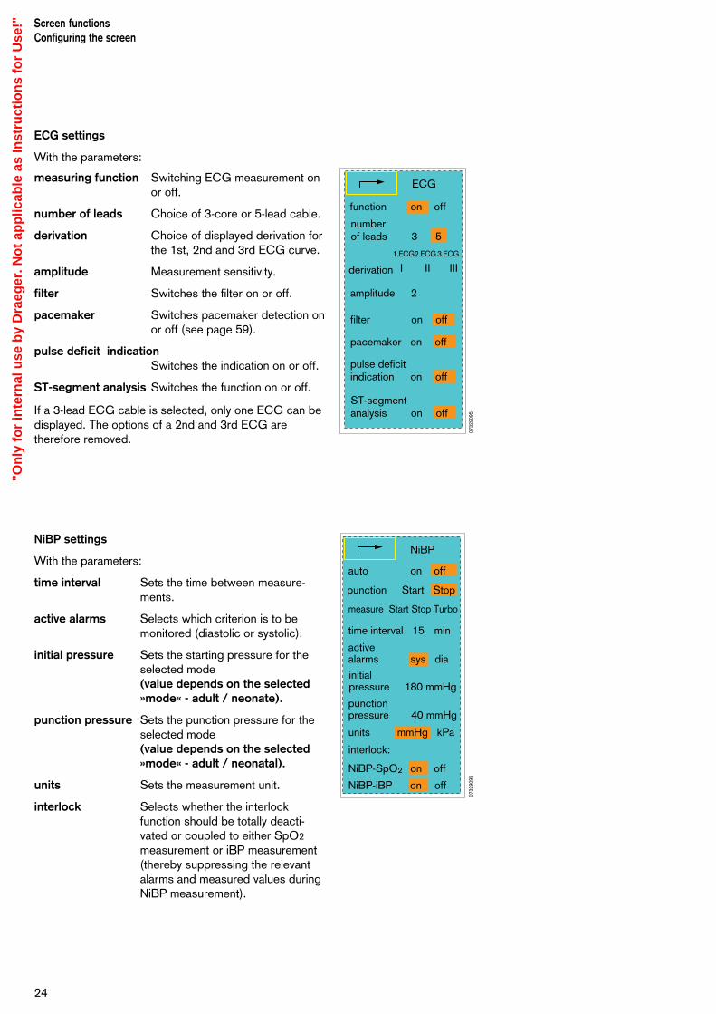
ECG settings
With the parameters:
measuring function Switching ECG measurement onor off.
number of leads Choice of 3-core or 5-lead cable.
derivation Choice of displayed derivation forthe 1st, 2nd and 3rd ECG curve.
amplitude Measurement sensitivity.
filter Switches the filter on or off.
pacemaker Switches pacemaker detection onor off (see page 59).
pulse deficit indicationSwitches the indication on or off.
ST-segment analysis Switches the function on or off.
If a 3-lead ECG cable is selected, only one ECG can bedisplayed. The options of a 2nd and 3rd ECG aretherefore removed.
NiBP settings
With the parameters:
time interval Sets the time between measure-ments.
active alarms Selects which criterion is to bemonitored (diastolic or systolic).
initial pressure Sets the starting pressure for theselected mode (value depends on the selected»mode« - adult / neonate).
punction pressure Sets the punction pressure for theselected mode(value depends on the selected»mode« - adult / neonatal).
units Sets the measurement unit.
interlock Selects whether the interlockfunction should be totally deacti-vated or coupled to either SpO2
measurement or iBP measurement(thereby suppressing the relevantalarms and measured values duringNiBP measurement).
Screen functionsConfiguring the screen
24
ECG
function on off
numberof leads 3 5
1.ECG2.ECG 3.ECG
derivation
ST-segmentanalysis on off
pulse deficit indication on off
pacemaker on off
filter on off
amplitude 2
I IIIII
NiBP
auto on off
punction Start Stop
measure Start Stop Turbo
time interval 15 min
active alarms sys dia
initial pressure 180 mmHg
punction pressure 40 mmHg
units mmHg kPa
interlock:
NiBP-SpO2 on off
NiBP-iBP on off
0732
9095
0732
9095
"On
ly f
or
inte
rnal
use
by
Dra
eger
. No
t ap
plic
able
as
Inst
ruct
ion
s fo
r U
se!"
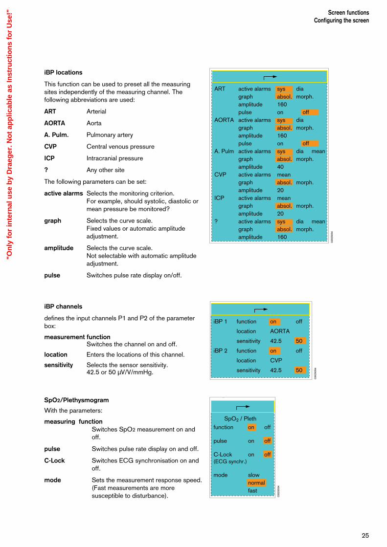
iBP locations
This function can be used to preset all the measuringsites independently of the measuring channel. Thefollowing abbreviations are used:
ART Arterial
AORTA Aorta
A. Pulm. Pulmonary artery
CVP Central venous pressure
ICP Intracranial pressure
? Any other site
The following parameters can be set:
active alarms Selects the monitoring criterion.For example, should systolic, diastolic ormean pressure be monitored?
graph Selects the curve scale.Fixed values or automatic amplitudeadjustment.
amplitude Selects the curve scale.Not selectable with automatic amplitudeadjustment.
pulse Switches pulse rate display on/off.
iBP channels
defines the input channels P1 and P2 of the parameterbox:
measurement functionSwitches the channel on and off.
location Enters the locations of this channel.
sensitivity Selects the sensor sensitivity.42.5 or 50 µV/V/mmHg.
SpO2/Plethysmogram
With the parameters:
measuring function Switches SpO2 measurement on andoff.
pulse Switches pulse rate display on and off.
C-Lock Switches ECG synchronisation on andoff.
mode Sets the measurement response speed.(Fast measurements are moresusceptible to disturbance).
25
Screen functionsConfiguring the screen
sysabsol.160onsysabsol.160onsysabsol.40meanabsol.20meanabsol.20sysabsol.160
ART
AORTA
A. Pulm
CVP
ICP
?
active alarmsgraphamplitudepulseactive alarmsgraphamplitudepulseactive alarmsgraphamplitudeactive alarmsgraphamplitudeactive alarmsgraphamplitudeactive alarmsgraphamplitude
mean
mean
diamorph.
offdiamorph.
offdiamorph.
morph.
morph.
diamorph.
iBP 1
iBP 2
function
location
sensitivity
function
location
sensitivity
on
AORTA
42.5
on
CVP
42.5
off
50
off
50
2
function
pulse
C-Lock(ECG synchr.)
mode
on
on
on
slownormalfast
off
off
off
SpO2 / Pleth
0392
9094
0392
9094
0392
9094
"On
ly f
or
inte
rnal
use
by
Dra
eger
. No
t ap
plic
able
as
Inst
ruct
ion
s fo
r U
se!"
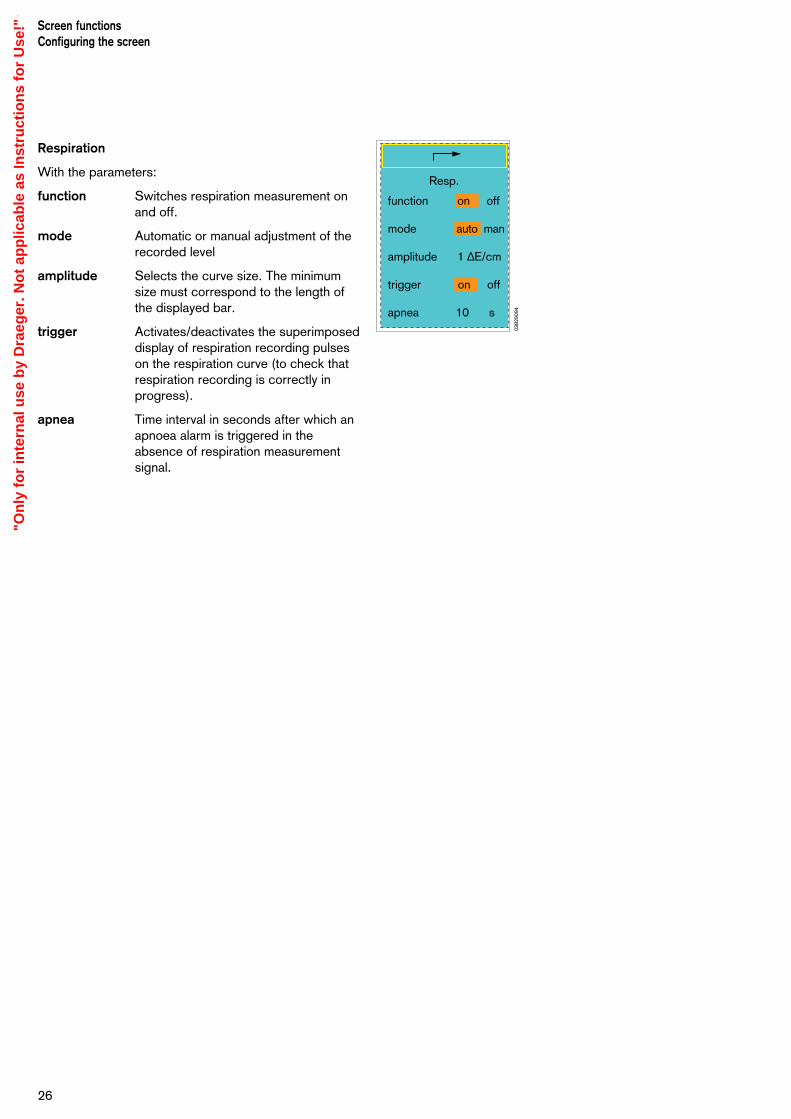
Respiration
With the parameters:
function Switches respiration measurement onand off.
mode Automatic or manual adjustment of therecorded level
amplitude Selects the curve size. The minimumsize must correspond to the length ofthe displayed bar.
trigger Activates/deactivates the superimposeddisplay of respiration recording pulseson the respiration curve (to check thatrespiration recording is correctly inprogress).
apnea Time interval in seconds after which anapnoea alarm is triggered in theabsence of respiration measurementsignal.
Screen functionsConfiguring the screen
26
Resp.
function on off
mode auto man
amplitude 1 ∆E/cm
trigger on off
apnea 10 s
0382
9094
"On
ly f
or
inte
rnal
use
by
Dra
eger
. No
t ap
plic
able
as
Inst
ruct
ion
s fo
r U
se!"

Configuring the standard screen withmodules
This menu is used to configure the screen. The machinestores the configuration and screen-related settings:
– standard screen
– colour
– curve speed
– general settings
When selected, the standard screen is immediatelyavailable with the desired setting.
The screen is made up of »modules«, which can beselected from the menu by means of the rotary control.
Configuring standard screen
Example: The screen structure is shown schematically onthe left-hand side of the screen. Alongside it, there is atable of graphical modules and numerical modules forselection.
Modules which are already selected are highlightedagainst an orange background, and their designations arecontained in the module blocks.
Move the cursor frame through the module table tothe module you want to change (in this example: iBP 1 and iBP 2) by turning the rotary control.
Press the rotary control to confirm.
The module block in the table goes grey and appearsin the schematic layout on the left, bordered by acursor.
The block can now be moved to the desired positionin the schematic layout by turning the rotary control.
When the rotary control is pressed to confirm, thedesired module is set in its current position on thescreen.
To delete a module, the relevant position on thescreen must be overwritten with a blank module.
27
Screen functionsConfiguring the screen
S hü /EM 6/Stb f / BS A fb 1 R
Standby/Configuration
10:3400:00
01-10-96Select a graph or a module by turning the rotary knob. Please confirm !
Default values
mode adult neon.
alarm limits
parameter
screen
acoustic
list entry
transport
RS 232 (Medibus)
RS 232 (Printer)
basic config.
screen
colours
curve speed
general settings
1. ECG HR
1. ECG x2 HR x 2
2. ECG Temp
3. ECG NiBP
iBP 1 iBP 1
iBP 2 iBP 2
iBP1+BP2 NiBP x2
Pleth SpO2
Pleth x 2 SpO2 x2
Resp. Resp.
Resp x 2 RR x 2
BLANK
Graph Module
screen
1. ECG
Temp NiBP
HR
Pleth SpO2
iBP 1
iBP 2iBP 1 + 2
alarms inactive !
S hü /EM 6/Stb f / BS A fb 2 R
Standby/Configuration
10:3400:00
01-10-96Please position selected parameter by turning the rotary knob. Please confirm !
Default values
mode adult neon.
alarm limits
parameter
screen
acoustic
list entry
transport
RS 232 (Medibus)
RS 232 (Printer)
basic config.
screen
colours
curve speed
general settings
screen
1. ECG
Resp. RR
HR
Pleth SpO2
iBP 1
iBP 2iBP 1 + 2
Graph Module
alarms inactive !
1. ECG HR
1. ECG x2 HR x 2
2. ECG Temp
3. ECG NiBP
iBP 1 iBP 1
iBP 2 iBP 2
iBP1+BP2 NiBP x2
Pleth SpO2
Pleth x 2 SpO2 x2
Resp. Resp.
Resp x 2 RR x 2
BLANK
0392
9094
0402
9094
"On
ly f
or
inte
rnal
use
by
Dra
eger
. No
t ap
plic
able
as
Inst
ruct
ion
s fo
r U
se!"

Examples of the selectable graph modules:
ECG graph ECG real-time graph. The derivation,amplitude and curve speed are freelyselectable in discrete increments.
This graph can also be displayed in adouble-height module.
iBP curves:
ART Displays the iBP curve for the arterialblood pressure in a separate graph ofsingle module height.
CVP Displays the iBP curve for the centralvenous blood pressure in a separategraph of single module height.
iBP 1 + iBP 2 Displays two iBP curves (ART and CVP)in a single graph with double the moduleheight.
Plethysmogram curveReal-time curve of the plethysmogrammeasured by the SpO2 sensor.
This curve can also be displayed in adouble-height module.
Respiration curveReal-time curve of the respirationcharacteristic.
This curve can also be displayed in adouble-height module.
28
Screen functionsConfiguring the screen
1. ECG
ZVD
ART
CVP
160
0
20
0
Respiration
iBP 1+iBP 2
60 0
ART130
CVP20
Pleth
1. ECG (Module double height)
Pleth (Module double height)
Respiration (Module double height)
0412
9094
"On
ly f
or
inte
rnal
use
by
Dra
eger
. No
t ap
plic
able
as
Inst
ruct
ion
s fo
r U
se!"
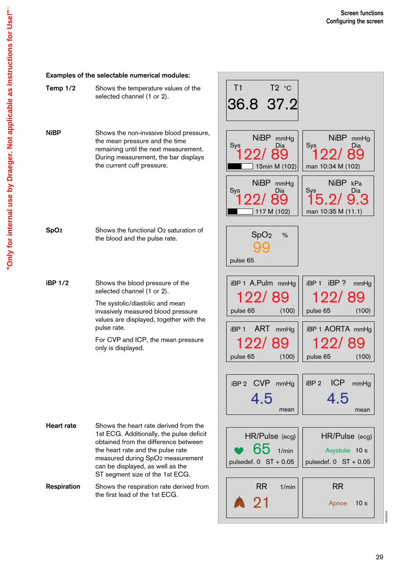
Examples of the selectable numerical modules:
Temp 1/2 Shows the temperature values of theselected channel (1 or 2).
NiBP Shows the non-invasive blood pressure,the mean pressure and the timeremaining until the next measurement.During measurement, the bar displaysthe current cuff pressure.
SpO2 Shows the functional O2 saturation ofthe blood and the pulse rate.
iBP 1/2 Shows the blood pressure of theselected channel (1 or 2).
The systolic/diastolic and meaninvasively measured blood pressurevalues are displayed, together with thepulse rate.
For CVP and ICP, the mean pressureonly is displayed.
Heart rate Shows the heart rate derived from the1st ECG. Additionally, the pulse deficitobtained from the difference betweenthe heart rate and the pulse ratemeasured during SpO2 measurementcan be displayed, as well as the ST segment size of the 1st ECG.
Respiration Shows the respiration rate derived fromthe first lead of the 1st ECG.
29
Screen functionsConfiguring the screen
36.8 37.2T1 T2 °C
15min M (102)
SysmmHgDia
122/ 89NiBP
Sys
man 10:34 M (102)
man 10:35 M (11.1)
mmHgDia
122/ 89NiBP
117 M (102)
SysmmHgDia
122/ 89NiBP
SyskPaDia
15.2/ 9.3NiBP
99pulse 65
SpO2 %
mmHg mmHg
mmHg
1/min
1/min
(ecg)
mmHg
4.5mean
CVPiBP 2
122/ 89(100)
ARTiBP 1
pulse 65
122/ 89(100)
AORTAiBP 1
pulse 65
mmHg
122/ 89(100)
A.PulmiBP 1
pulse 65
mmHg
122/ 89(100)
iBP ?iBP 1
pulse 65
65pulsedef. 0 ST + 0.05
HR/Pulse
iBP 2
4.5mean
ICP
21RR
10 s
(ecg)
Asystolie
10 sApnoe
pulsedef. 0 ST + 0.05
HR/Pulse
RR
0422
9094
"On
ly f
or
inte
rnal
use
by
Dra
eger
. No
t ap
plic
able
as
Inst
ruct
ion
s fo
r U
se!"

Configuring the colour settings
Colour settings always apply to all the featuresassociated with a parameter. The numerical modules, if configured for colour, are the same colour as theircorresponding curves.
Select and confirm the desired parameter.
Change the colour by turning the rotary control. The colours are displayed in the sequence shown inthe colour bar at the top of the menu.
Confirm the desired colour.
Configuring the background settings
dark Black background, light curves andnumbers. Preferably used in a darkenvironment.
light White background, dark curves andnumbers. Preferably used in a brightenvironment.
colour modules
yes The numerical modules will be thesame colour as the correspondingcurves.
no The numerical modules are displayedin black-and-white.
Example:
Screen with dark background
Screen functionsConfiguring the screen
30
Standby/Configuration
10:3400:00
01-10-96 Select a parameter. Please confirm !Select a colour. Please confirm !
Default values
mode adult neon.
alarm limits
parameter
screen
acoustic
list entry
transport
RS 232 (Medibus)
RS 232 (Printer)
basic config.
screen
colours
curve speed
general settings
ARTAORTAA.PulmCVPICPiBP ?ECGNiBPSpO2Resp.Temp
alarms inactive !
background bright dark
modulescoloured yes no
0432
9094
0442
9094
10:3400:00
01-10-96
standard screen - adultAdvisory:Caution:Warning:
1. ECGII
1mV
Pleth
auto setlimits
alarminfo
screenconfig.
para-meter
timerstart
limits
config.
65pulse def. 0 ST + 0.05
HR/Pulse (ECG)
122/ 89(100)
ARTiBP 1
99pulse 65
pulse 65
4.5mean
CVPiBP 2
15min M (102)
SysmmHgDia
SpO2
122/ 89NiBP
36.8 37.2T1 T2 °C
ART
CVP
130
10
80
0
0952
9095
"On
ly f
or
inte
rnal
use
by
Dra
eger
. No
t ap
plic
able
as
Inst
ruct
ion
s fo
r U
se!"
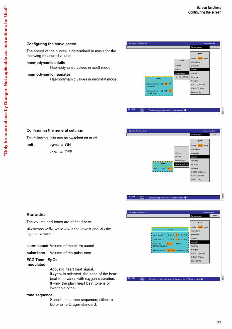
Configuring the curve speed
The speed of the curves is determined in mm/s for thefollowing measured values:
haemodynamic adultsHaemodynamic values in adult mode.
haemodynamic neonatesHaemodynamic values in neonatal mode.
Configuring the general settings
The following units can be switched on or off:
unit »yes« = ON
»no« = OFF
Acoustic
The volume and tones are defined here.
»0« means »off«, while »1« is the lowest and »9« thehighest volume.
alarm sound Volume of the alarm sound
pulse tone Volume of the pulse tone
ECG Tone - SpO2
modulatedAcoustic heart beat signal.If »yes« is selected, the pitch of the heartbeat tone varies with oxygen saturation. If »no« the plain heart beat tone is ofinvariable pitch.
tone sequence Specifies the tone sequence, either toEuro- or to Dräger standard.
31
Screen functionsConfiguring the screen
Standby/Configuration
10:3400:00
01-10-96Screen configuration menu. Please confirm !
Default values
mode adult neon.
alarm limits
parameter
screen
acoustic
list entry
transport
RS 232 (Medibus)
RS 232 (Printer)
basic config.
screen
colours
curve speed
general settings
haemodynamic 12,5 25 50adult mm/s
haemodynamic 12,5 25 50neonate mm/s
alarms inactive !
Standby/Configuration
10:3400:00
01-10-96Screen configuration menu. Please confirm !
Default values
mode adult neon.
alarm limits
parameter
screen
acoustic
list entry
transport
RS 232 (Medibus)
RS 232 (Printer)
basic config.
screen
colours
curve speed
general settings
units yes no
alarms inactive !
Standby/Configuration
10:3400:00
01-10-96Alarm sound and pulse tone configuration menu. Please confirm !
Default values
mode adult neon.
alarm limits
parameter
screen
acoustic
list entry
transport
RS 232 (Medibus)
RS 232 (Printer)
basic config.
alarm sound 1 2 3 4 5 6 7 8 9
pulse tone 0 1 2 3 4 5 6 7 8 9
pulse tone ECG Pleth.SpO2 modulated
tone sequence DRÄGER Euro-Standard
alarms inactive !
0452
9094
0112
9094
0462
9094
"On
ly f
or
inte
rnal
use
by
Dra
eger
. No
t ap
plic
able
as
Inst
ruct
ion
s fo
r U
se!"
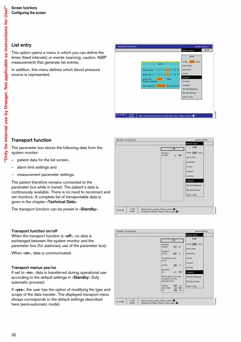
List entry
This option opens a menu in which you can define thetimes (fixed intervals) or events (warning, caution, NiBPmeasurement) that generate list entries.
In addition, this menu defines which blood pressuresource is represented.
Transport function
The parameter box stores the following data from thesystem monitor:
– patient data for the list screen,
– alarm limit settings and
– measurement parameter settings.
The patient therefore remains connected to theparameter box while in transit. The patient's data iscontinuously available. There is no need to reconnect andset monitors. A complete list of transportable data isgiven in the chapter »Technical Data«.
The transport function can be preset in »Standby«.
Transport function on/offWhen the transport function is »off«, no data isexchanged between the system monitor and theparameter box (for stationary use of the parameter box).
When »on«, data is communicated.
Transport menus yes/noIf set to »no«, data is transferred during operational useaccording to the default settings in »Standby« (fullyautomatic process).
If »yes«, the user has the option of modifying the type andscope of the data transfer. The displayed transport menualways corresponds to the default settings describedhere (semi-automatic mode).
Screen functionsConfiguring the screen
32
Standby/Configuration
10:3400:00
01-10-96Alarm sound and pulse tone configuration menu. Please confirm !
Default values
mode adult neon.
alarm limits
parameter
screen
acoustic
list entry
transport
RS 232 (Medibus)
RS 232 (Printer)
basic config.
alarm sound 1 2 3 4 5 6 7 8 9
pulse tone 0 1 2 3 4 5 6 7 8 9
pulse tone ECG Pleth.SpO2 modulated
tone sequence DRÄGER Euro-Standard
alarms inactive !
Standby / Configuration
11:5900:00
01.04.96
Default values
alarms inactive!
Select a menu position. Please confirm !Change the settings. Please confirm again !
mode adult neon.
alarm limits
parameter
screen
acoustic
list entry
transport
RS 232 (Medibus)
RS 232 (Printer)
basic config.
transportfunction on off
transport-menus yes no
The patient is newto the:
monitor yes no
parameterbox yes no
Which data do you wantto transfer from theparameter box?
settings yes noalarm limits yes nolist yes no
Standby / Configuration
11:5900:00
01.04.96
Default values
alarms inactive!
Select a menu position. Please confirm !Change the settings. Please confirm again !
mode adult neon.
alarm limits
parameter
screen
acoustic
list entry
transport
RS 232 (Medibus)
RS 232 (Printer)
basic config.
transportfunction on off
0472
9094
0482
9094
0492
9094
"On
ly f
or
inte
rnal
use
by
Dra
eger
. No
t ap
plic
able
as
Inst
ruct
ion
s fo
r U
se!"
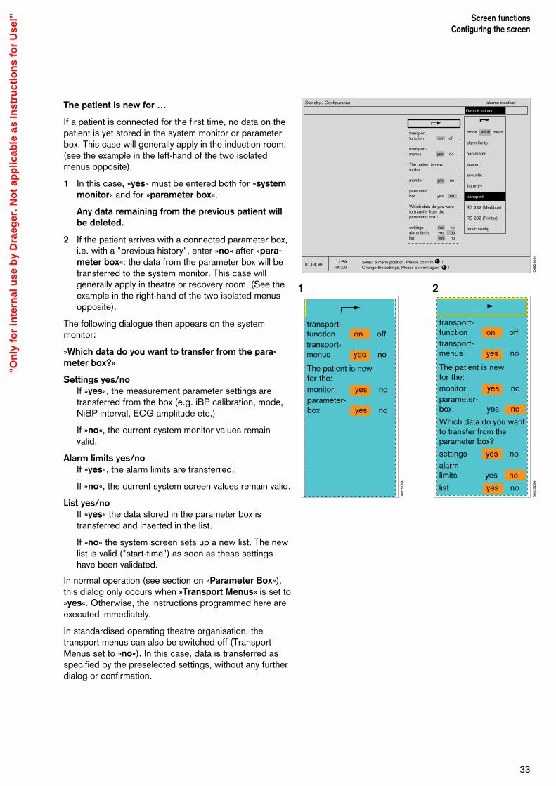
The patient is new for …
If a patient is connected for the first time, no data on thepatient is yet stored in the system monitor or parameterbox. This case will generally apply in the induction room.(see the example in the left-hand of the two isolatedmenus opposite).
1 In this case, »yes« must be entered both for »systemmonitor« and for »parameter box«.
Any data remaining from the previous patient willbe deleted.
2 If the patient arrives with a connected parameter box,i.e. with a "previous history", enter »no« after »para-meter box«: the data from the parameter box will betransferred to the system monitor. This case willgenerally apply in theatre or recovery room. (See theexample in the right-hand of the two isolated menusopposite).
The following dialogue then appears on the systemmonitor:
»Which data do you want to transfer from the para-meter box?«
Settings yes/noIf »yes«, the measurement parameter settings aretransferred from the box (e.g. iBP calibration, mode,NiBP interval, ECG amplitude etc.)
If »no«, the current system monitor values remainvalid.
Alarm limits yes/noIf »yes«, the alarm limits are transferred.
If »no«, the current system screen values remain valid.
List yes/noIf »yes« the data stored in the parameter box istransferred and inserted in the list.
If »no« the system screen sets up a new list. The newlist is valid ("start-time") as soon as these settingshave been validated.
In normal operation (see section on »Parameter Box«),this dialog only occurs when »Transport Menus« is set to»yes«. Otherwise, the instructions programmed here areexecuted immediately.
In standardised operating theatre organisation, thetransport menus can also be switched off (TransportMenus set to »no«). In this case, data is transferred asspecified by the preselected settings, without any furtherdialog or confirmation.
33
Screen functionsConfiguring the screen
Standby / Configuration
11:5900:00
01.04.96
Default values
alarms inactive!
Select a menu position. Please confirm !Change the settings. Please confirm again !
mode adult neon.
alarm limits
parameter
screen
acoustic
list entry
transport
RS 232 (Medibus)
RS 232 (Printer)
basic config.
transportfunction on off
transport-menus yes no
The patient is newto the:
monitor yes no
parameterbox yes no
Which data do you wantto transfer from theparameter box?
settings yes noalarm limits yes nolist yes no
The patient is newfor the:monitor yes noparameter-box yes no
transport-function on offtransport-menus yes no
transport-function on offtransport-menus yes no
The patient is newfor the:monitor yes noparameter-box yes no
Which data do you wantto transfer from theparameter box?
settings yes noalarmlimits yes no
list yes no
1 2
0492
9094
0692
9094
0692
9094
"On
ly f
or
inte
rnal
use
by
Dra
eger
. No
t ap
plic
able
as
Inst
ruct
ion
s fo
r U
se!"
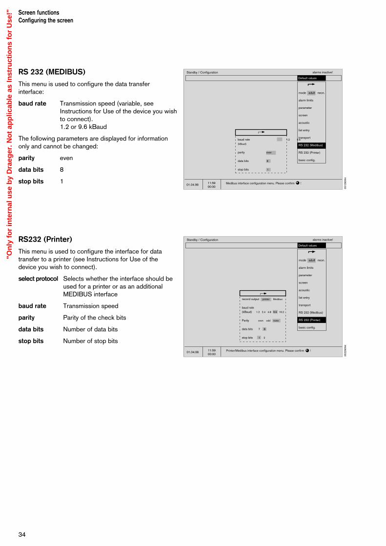
RS 232 (MEDIBUS)
This menu is used to configure the data transferinterface:
baud rate Transmission speed (variable, seeInstructions for Use of the device you wishto connect).1.2 or 9.6 kBaud
The following parameters are displayed for informationonly and cannot be changed:
parity even
data bits 8
stop bits 1
RS232 (Printer)
This menu is used to configure the interface for datatransfer to a printer (see Instructions for Use of thedevice you wish to connect).
select protocol Selects whether the interface should beused for a printer or as an additionalMEDIBUS interface
baud rate Transmission speed
parity Parity of the check bits
data bits Number of data bits
stop bits Number of stop bits
Screen functionsConfiguring the screen
34
Standby / Configuration
11:5900:00
01.04.96
Default values
alarms inactive!
Printer/Medibus interface configuration menu. Please confirm !
mode adult neon.
alarm limits
parameter
screen
acoustic
list entry
transport
RS 232 (Medibus)
RS 232 (Printer)
basic config.
record output printer Medibus
baud rate(kBaud) 1.2 2.4 4.8 9.6 19.2
Parity even odd none
data bits 7 8
stop bits 1 2
Standby / Configuration
11:5900:00
01.04.96
Default values
alarms inactive!
Medibus interface configuration menu. Please confirm !
mode adult neon.
alarm limits
parameter
screen
acoustic
list entry
transport
RS 232 (Medibus)
RS 232 (Printer)
basic config.
baud rate 1.2 9.6
(kBaud)
parity even
data bits 8
stop bits 1
0512
9094
0522
9094
"On
ly f
or
inte
rnal
use
by
Dra
eger
. No
t ap
plic
able
as
Inst
ruct
ion
s fo
r U
se!"
0052
9094
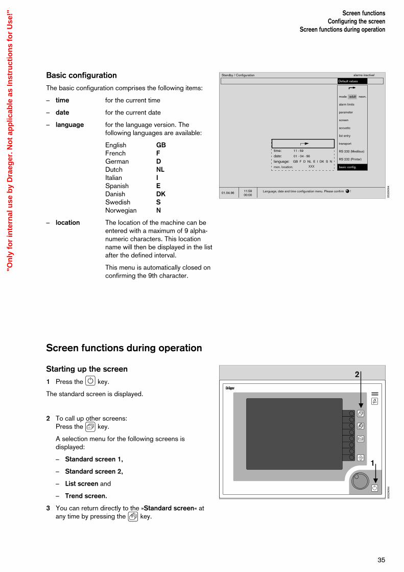
Basic configuration
The basic configuration comprises the following items:
– time for the current time
– date for the current date
– language for the language version. Thefollowing languages are available:
English GBFrench FGerman DDutch NLItalian ISpanish EDanish DKSwedish SNorwegian N
– location The location of the machine can beentered with a maximum of 9 alpha-numeric characters. This locationname will then be displayed in the listafter the defined interval.
This menu is automatically closed onconfirming the 9th character.
Screen functions during operation
Starting up the screen
1 Press the E key.
The standard screen is displayed.
2 To call up other screens:Press the S key.
A selection menu for the following screens isdisplayed:
– Standard screen 1,
– Standard screen 2,
– List screen and
– Trend screen.
3 You can return directly to the »Standard screen« atany time by pressing the Q key.
35
Screen functionsConfiguring the screen
Screen functions during operation
Standby / Configuration
11:5900:00
01.04.96
Default values
alarms inactive!
Language, date and time configuration menu. Please confirm !
mode adult neon.
alarm limits
parameter
screen
acoustic
list entry
transport
RS 232 (Medibus)
RS 232 (Printer)
basic config.
time: 11 : 59
date: 01 - 04 - 96
language: GB F D NL E I DK S N
mon. location: XXX
D
1-2--
Stop
2
1
0532
9094
"On
ly f
or
inte
rnal
use
by
Dra
eger
. No
t ap
plic
able
as
Inst
ruct
ion
s fo
r U
se!"

– Standard screencontains the graph and measured value fieldsconfigured by the user.
– The list screencontains all the measured values and alarms whichhave been saved and makes it easier to complete theanaesthetic record (see page 38). The uppermostgraph of th standard screen is shown at the top.
– The trend screenshows graphically the measured values over time. The uppermost graph of the standard screen isshown at the top.
Screen functionsScreen functions during operation
36
10:3400:00
01-10-96
standard screen - adultAdvisory:Caution:Warning:
65pulse def. 0 ST + 0.05
122/ 89(100)
ARTiBP 1
4.5mean
CVP
99pulse 65
pulse 65
15min M (102)
SysmmHgDia
SpO2
122/ 89NiBP
36.8 37.2T1 T2 °C
iBP 2
auto setlimits
alarminfo
screenconfig.
para-meter
timerstart
limits
config.
1. ECGII
1mV
Pleth
ART
CVP
130
10
80
0
HR/Pulse (ECG)
11:3400:00
01-10-96
list screen - adultAdvisory:Caution:Warning:
intubation
start ofsurgery
positionchange
extuba-tion
start ofanaesthesia
end ofsurgery
event
1. ECGII
1mV
65pulse def. 0 ST + 0.05
Manual list entry by
time
10:55 interval 2 01-10-9610:55 IND-210:55 11:0011:0511:08 intubation11:1011:1311:1511:20 interval 1 01-10-9611:20 OP-2 11:20 11:25 11:3011:32 start of surgery
HR/Pulse1/min
6467
636263
6362
NiBP mmHgSys/M/Dia
120/100/90123/103/88
120/100/90123/103/88128/107/93
120/100/90122/102/89
SpO2%
90 97
96 90 97
95 97
CO2Vol. %Fet
3537
313433
3537
PAW mbar peak/PEEP
32/3 31/3
33/3 31/3 30/3
32/3 31/3
Warning
SPO2
SPO2
!!!
!!!
MVL/min
6.4 6.3
6.2 6.1 6.0
6.4 6.3
Cpatml/mbar
1212
121212
1212
O2Vol. %Fi
2131
323133
3031
anaesth.agentFi
ENF1.41.4 1.21.21.1
ISO1.41.4
temp°CT1
36.836.9
36.736.836.9
36.836.9
config. list entry next page preceding page
HR/Pulse (ECG)
10:3400:00
01-10-96 Select a trend sector and magnify by confirming !
NiBP SpO2
HR/RRIBP 1200
100
0
100
60
80
200
100
0
11:00 12:00 13:00
Sys
MDia
Sys
MDia
200
100
0
11:00 12:00 13:00
1. ECG II
1mV
fulltrend
config.
trend screen - adultAdvisory:Caution:Warning:
65pulse def. 0 ST + 0.05
HR/Pulse (ECG)
0142
9094
0152
9094
0162
9094
"On
ly f
or
inte
rnal
use
by
Dra
eger
. No
t ap
plic
able
as
Inst
ruct
ion
s fo
r U
se!"
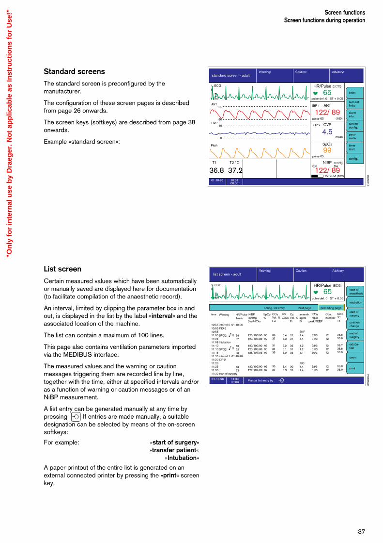
Standard screens
The standard screen is preconfigured by themanufacturer.
The configuration of these screen pages is describedfrom page 26 onwards.
The screen keys (softkeys) are described from page 38onwards.
Example »standard screen«:
List screen
Certain measured values which have been automaticallyor manually saved are displayed here for documentation(to facilitate compilation of the anaesthetic record).
An interval, limited by clipping the parameter box in andout, is displayed in the list by the label »interval« and theassociated location of the machine.
The list can contain a maximum of 100 lines.
This page also contains ventilation parameters importedvia the MEDIBUS interface.
The measured values and the warning or cautionmessages triggering them are recorded line by line,together with the time, either at specified intervals and/oras a function of warning or caution messages or of anNiBP measurement.
A list entry can be generated manually at any time bypressing U If entries are made manually, a suitabledesignation can be selected by means of the on-screensoftkeys:
For example: »start of surgery«»transfer patient«
»Intubation«
A paper printout of the entire list is generated on anexternal connected printer by pressing the »print« screenkey.
37
Screen functionsScreen functions during operation
10:3400:00
01-10-96
standard screen - adultAdvisory:Caution:Warning:
65pulse def. 0 ST + 0.05
122/ 89(100)
ARTiBP 1
4.5mean
CVP
99pulse 65
pulse 65
15min M (102)
SysmmHgDia
SpO2
122/ 89NiBP
36.8 37.2T1 T2 °C
iBP 2
auto setlimits
alarminfo
screenconfig.
para-meter
timerstart
limits
config.
1. ECGII
1mV
Pleth
ART
CVP
130
10
80
0
HR/Pulse (ECG)
11:3400:00
01-10-96
list screen - adultAdvisory:Caution:Warning:
intubation
start ofsurgery
positionchange
extuba-tion
start ofanaesthesia
end ofsurgery
event
1. ECGII
1mV
65pulse def. 0 ST + 0.05
Manual list entry by
time
10:55 interval 2 01-10-9610:55 IND-210:55 11:0011:0511:08 intubation11:1011:1311:1511:20 interval 1 01-10-9611:20 OP-2 11:20 11:25 11:3011:32 start of surgery
HR/Pulse1/min
6467
636263
6362
NiBP mmHgSys/M/Dia
120/100/90123/103/88
120/100/90123/103/88128/107/93
120/100/90122/102/89
SpO2%
90 97
96 90 97
95 97
CO2Vol. %Fet
3537
313433
3537
PAW mbar peak/PEEP
32/3 31/3
33/3 31/3 30/3
32/3 31/3
Warning
SPO2
SPO2
!!!
!!!
MVL/min
6.4 6.3
6.2 6.1 6.0
6.4 6.3
Cpatml/mbar
1212
121212
1212
O2Vol. %Fi
2131
323133
3031
anaesth.agentFi
ENF1.41.4 1.21.21.1
ISO1.41.4
temp°CT1
36.836.9
36.736.836.9
36.836.9
config. list entry next page preceding page
HR/Pulse (ECG)
0142
9094
0152
9094
"On
ly f
or
inte
rnal
use
by
Dra
eger
. No
t ap
plic
able
as
Inst
ruct
ion
s fo
r U
se!"

The list may continue for several pages, so that it may benecessary to »leaf through« in order to locate a specificentry.
Return to previous page:
Turn rotary control to select »previous page« andpress to confirm.
Continue to next page:
Turn rotary control to select »next page« and confirm.
Define list entry:
Select »list entry« with the rotary control and confirm.A menu appears for you to select at what times (fixedintervals) or events (warning, caution, NiBP measure-ment) list entries should be made.
In addition, this option is used to define the bloodpressure.
The list entries for the currently used screen can also bemodified later.
Deleting the list and trend memory:The trend memory and list are deleted together. They canonly be deleted in »Standby« mode. If the parameter boxis connected, the data in the parameter box will also bedeleted!
Press the E key to switch over to standby mode.
Press the »delete trend« softkey.
The system asks you to confirm that you are sure youwant to delete the trend.
Press the »delete« softkey to confirm.
To restore the unchanged screen without deleting,press »do not delete«.
Screen functionsScreen functions during operation
38
deletetrend
config.
Switch on with E
Standby
Data ManagerSW-Version 2.n
02-12-97
ParameterboxSW-Version 2.n
PM 8060 Vitara
0102
9094
11:3400:00
01-10-96
list screen - adultAdvisory:Caution:Warning:
intubation
start ofsurgery
positionchange
extuba-tion
start ofanaesthesia
end ofsurgery
event
1. ECGII
1mV
65pulse def. 0 ST + 0.05
Manual list entry by
time
10:55 interval 2 01-10-9610:55 IND-210:55 11:0011:0511:08 intubation11:1011:1311:1511:20 interval 1 01-10-9611:20 OP-2 11:20 11:25 11:3011:32 start of surgery
HR/Pulse1/min
6467
636263
6362
NiBP mmHgSys/M/Dia
120/100/90123/103/88
120/100/90123/103/88128/107/93
120/100/90122/102/89
SpO2%
90 97
96 90 97
95 97
CO2Vol. %Fet
3537
313433
3537
PAW mbar peak/PEEP
32/3 31/3
33/3 31/3 30/3
32/3 31/3
Warning
SPO2
SPO2
!!!
!!!
MVL/min
6.4 6.3
6.2 6.1 6.0
6.4 6.3
Cpatml/mbar
1212
121212
1212
O2Vol. %Fi
2131
323133
3031
anaesth.agentFi
ENF1.41.4 1.21.21.1
ISO1.41.4
temp°CT1
36.836.9
36.736.836.9
36.836.9
config. list entry next page preceding page
HR/Pulse (ECG)
0152
9094
"On
ly f
or
inte
rnal
use
by
Dra
eger
. No
t ap
plic
able
as
Inst
ruct
ion
s fo
r U
se!"
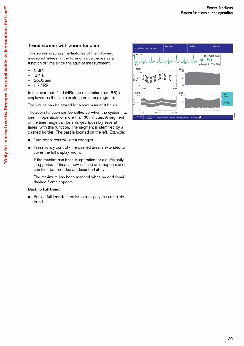
Trend screen with zoom function
This screen displays the histories of the followingmeasured values, in the form of value curves as afunction of time since the start of measurement:
– NiBP,– iBP 1,– SpO2 and– HR / RR
In the heart rate field (HR), the respiration rate (RR) isdisplayed on the same scale (cardio respirogram).
The values can be stored for a maximum of 8 hours.
The zoom function can be called up when the system hasbeen in operation for more than 30 minutes. A segmentof the time range can be enlarged (possibly severaltimes) with this function. The segment is identified by adashed border. The past is located on the left. Example:
Turn rotary control - area changes.
Press rotary control - the dashed area is extended tocover the full display width.
If the monitor has been in operation for a sufficientlylong period of time, a new dashed area appears andcan then be extended as described above.
The maximum has been reached when no additionaldashed frame appears.
Back to full trend:
Press »full trend« in order to redisplay the completetrend.
39
Screen functionsScreen functions during operation
10:3400:00
01-10-96 Select a trend sector and magnify by confirming !
NiBP SpO2
HR/RRIBP 1200
100
0
100
60
80
200
100
0
11:00 12:00 13:00
Sys
MDia
Sys
MDia
200
100
0
11:00 12:00 13:00
1. ECG II
1mV
fulltrend
config.
trend screen - adultAdvisory:Caution:Warning:
65pulse def. 0 ST + 0.05
HR/Pulse (ECG)
0162
9094
"On
ly f
or
inte
rnal
use
by
Dra
eger
. No
t ap
plic
able
as
Inst
ruct
ion
s fo
r U
se!"
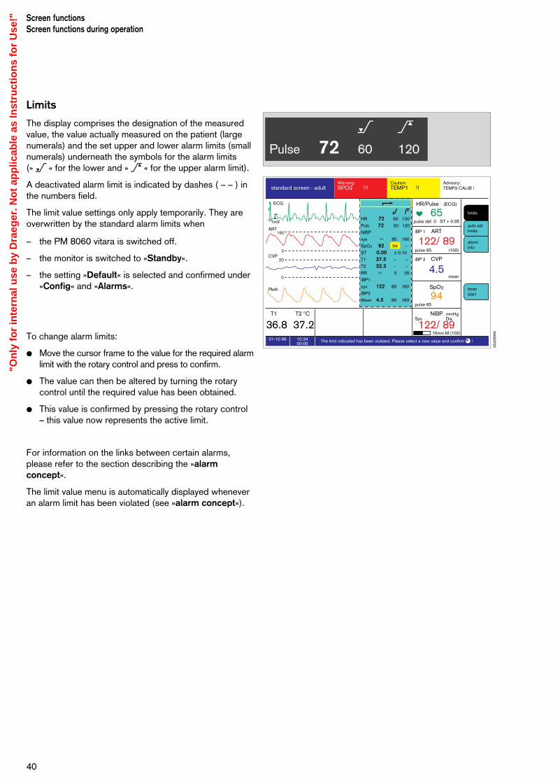
Limits
The display comprises the designation of the measuredvalue, the value actually measured on the patient (largenumerals) and the set upper and lower alarm limits (smallnumerals) underneath the symbols for the alarm limits (» < « for the lower and » > « for the upper alarm limit).
A deactivated alarm limit is indicated by dashes ( – – ) inthe numbers field.
The limit value settings only apply temporarily. They areoverwritten by the standard alarm limits when
– the PM 8060 vitara is switched off.
– the monitor is switched to »Standby«.
– the setting »Default« is selected and confirmed under»Config« and »Alarms«.
To change alarm limits:
Move the cursor frame to the value for the required alarmlimit with the rotary control and press to confirm.
The value can then be altered by turning the rotarycontrol until the required value has been obtained.
This value is confirmed by pressing the rotary control– this value now represents the active limit.
For information on the links between certain alarms,please refer to the section describing the »alarmconcept«.
The limit value menu is automatically displayed wheneveran alarm limit has been violated (see »alarm concept«).
Screen functionsScreen functions during operation
40
< >Pulse 72 60 120
10:3400:00
01-10-96 The limit indicated has been violated. Please select a new value and confirm !
standard screen - adultAdvisory:Caution:Warning:TEMP2 CALIB !TEMP1 !!SPO2 !!!
1. ECGII
1mV
ART
CVP
Pleth
65pulse def. 0 ST + 0.05
HR/Pulse (ECG)
122/ 89(100)
ARTiBP 1
4.5mean
CVP
94pulse 65
pulse 65
15min M (102)
SysmmHgDia
SpO2
122/ 89NiBP
36.8 37.2T1 T2 °C
iBP 2
160
20
0
0
auto setlimits
alarminfo
timerstart
limitsHR 72 50 120
Puls 72 50 120
NiBP
sys -- 80 160
SpO2 92 94 --
ST 0.00 ± 0.10
T1 37.5 -- --
T2 32.2 -- --
RR -- 5 25
iBP1
sys 122 80 160
iBP2
Mean 4.5 80 160
0542
9094
"On
ly f
or
inte
rnal
use
by
Dra
eger
. No
t ap
plic
able
as
Inst
ruct
ion
s fo
r U
se!"
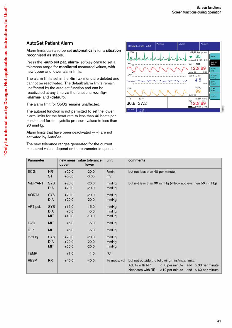
AutoSet Patient Alarm
Alarm limits can also be set automatically for a situationrecognised as stable.
Press the »auto set pat. alarm« softkey once to set atolerance range for monitored measured values, withnew upper and lower alarm limits.
The alarm limits set in the »limits« menu are deleted andcannot be reactivated. The default alarm limits remainunaffected by the auto set function and can bereactivated at any time via the functions »config«,»alarms« and »default«.
The alarm limit for SpO2 remains unaffected.
The autoset function is not permitted to set the loweralarm limits for the heart rate to less than 40 beats perminute and for the systolic pressure values to less than90 mmHg.
Alarm limits that have been deactivated (– –) are notactivated by AutoSet.
The new tolerance ranges generated for the currentmeasured values depend on the parameter in question:
41
Screen functionsScreen functions during operation
10:3400:00
01-10-96
standard screen - adultAdvisory:Caution:Warning:
65pulse def. 0 ST + 0.05
122/ 89(100)
ARTiBP 1
4.5mean
CVP
99pulse 65
pulse 65
15min M (102)
SysmmHgDia
SpO2
122/ 89NiBP
36.8 37.2T1 T2 °C
iBP 2
auto setlimits
alarminfo
screenconfig.
para-meter
timerstart
limits
config.
1. ECGII
1mV
Pleth
ART
CVP
130
10
80
0
HR/Pulse (ECG)
Parameter new meas. value tolerance unit commentsupper lower
ECG HR +20.0 -20.0 1/min but not less than 40 per minuteST +0.05 -0.05 mV
NiBP/ART SYS +20.0 -20.0 mmHg but not less than 90 mmHg (»Neo« not less then 50 mmHg) DIA +20.0 -20.0 mmHg
AORTA SYS +20.0 -20.0 mmHgDIA +20.0 -20.0 mmHg
ART pul. SYS +15.0 -15.0 mmHgDIA +5.0 -5.0 mmHgMIT +10.0 -10.0 mmHg
CVD MIT +5.0 -5.0 mmHg
ICP MIT +5.0 -5.0 mmHg
mmHg SYS +20.0 -20.0 mmHgDIA +20.0 -20.0 mmHgMIT +20.0 -20.0 mmHg
TEMP +1.0 -1.0 °C
RESP RR +40.0 -40.0 % meas. val but not outside the following min./max. limits:Adults with RR < 6 per minute and > 30 per minuteNeonates with RR < 12 per minute and > 60 per minute
0552
9095
"On
ly f
or
inte
rnal
use
by
Dra
eger
. No
t ap
plic
able
as
Inst
ruct
ion
s fo
r U
se!"
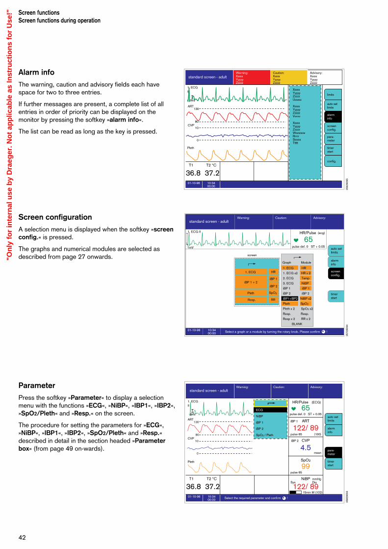
Alarm info
The warning, caution and advisory fields each havespace for two to three entries.
If further messages are present, a complete list of allentries in order of priority can be displayed on themonitor by pressing the softkey »alarm info«.
The list can be read as long as the key is pressed.
Screen configuration
A selection menu is displayed when the softkey »screenconfig.« is pressed.
The graphs and numerical modules are selected asdescribed from page 27 onwards.
Parameter
Press the softkey »Parameter« to display a selectionmenu with the functions »ECG«, »NiBP«, »IBP1«, »IBP2«,»SpO2/Pleth« and »Resp.« on the screen.
The procedure for setting the parameters for »ECG«,»NiBP«, »IBP1«, »IBP2«, »SpO2/Pleth« and »Resp.«described in detail in the section headed »Parameterbox« (from page 49 on-wards).
Screen functionsScreen functions during operation
42
10:3400:00
01-10-96
standard screen - adult
36.8 37.2T1 T2 °C
auto setlimits
alarminfo
screenconfig.
para-meter
timerstart
limits
config.
1mV
Pleth
ART
CVP
130
10
80
0
Warning:XxxxxYyyyyZzzzz
Caution:XxxxxYyyyyZzzzz
1. ECGII
Advisory:XxxxxYyyyyZzzzz
XxxxxYyyyyZzzzzUuuuu
XxxxxYyyyyZzzzzVvvvv
XxxxxYyyyyZzzzzWwwwwRrrrrSssssTtttt
10:3400:00
01-10-96 Select a graph or a module by turning the rotary knob. Please confirm !
standard screen - adultAdvisory:
S hü /EM 6/B t /St d /1 fi R
Caution:Warning:
auto setlimits
alarminfo
screenconfig.
timerstart
65pulse def. 0 ST + 0.05
1. ECG II
1mV
HR/Pulse (ecg)
screen
1. ECG
Resp. RR
HR
Pleth SpO2
iBP 1
iBP 2iBP 1 + 2
Graph Module
1. ECG HR
1. ECG x2 HR x 2
2. ECG Temp
3. ECG NiBP
iBP 1 iBP 1
iBP 2 iBP 2
iBP1+BP2 NiBP x2
Pleth SpO2
Pleth x 2 SpO2 x2
Resp. Resp.
Resp x 2 RR x 2
BLANK
10:3400:00
01-10-96 Select the required parameter and confirm !
standard screen - adultAdvisory:Caution:Warning:
1. ECGII
1mV
ART
CVP
Pleth
65pulse def. 0 ST + 0.05
122/ 89(100)
ARTiBP 1
4.5mean
CVP
99pulse 65
pulse 65
15min M (102)
SysmmHgDia
SpO2
122/ 89NiBP
36.8 37.2T1 T2 °C
iBP 2
130
10
80
0
auto setlimits
alarminfo
para-meter
timerstart
ECG
NiBP
iBP 1
iBP 2
SpO2 / Pleth
HR/Pulse (ECG)
0572
9094
0562
9095
0582
9094
"On
ly f
or
inte
rnal
use
by
Dra
eger
. No
t ap
plic
able
as
Inst
ruct
ion
s fo
r U
se!"

Timer
Press the »timer start« softkey to start the timer at »00 : 00«.
Format: »Min. : Sec.«
1 The timer reading is shown on the screen below thenormal time. The softkey changes automatically to»timer stop«.
Press the softkey again to stop the timer. The displaywill be cleared on switching to »Standby«.
Configuration
This softkey calls up the configuration menu. These settings will only remain valid until the machine isswitched off or switched to »standby« mode!
The menu for configuring the default values is displayedwith the following settings:
Settings
– mode Switches between adult andneonatal modes (toggle function).
– alarm sound Sets the volume.
– pulse tone Sets the volume of the pulse tone.
– ECG-Tone - SpO2
modulated Acoustic heart beat signal.If »yes« is selected here, the pitchof the heart beat tone varies withthe oxygen saturation.If »no«, the heart beat toneremains of invariable pitch.
– colour Sets the colour configuration.
– curve speed Determines the speed of thehaemodynamic curves.
– call standard Activates all parameter settingsconfigured in »Standby« (but notthe default alarm limits!).
43
Screen functionsScreen functions during operation
10:3400:00
01-10-96
standard screen - adultAdvisory:Caution:Warning:
65pulse def. 0 ST + 0.05
122/ 89(100)
ARTiBP 1
4.5mean
CVP
99pulse 65
pulse 65
15min M (102)
SysmmHgDia
SpO2
122/ 89NiBP
36.8 37.2T1 T2 °C
iBP 2
auto setlimits
alarminfo
screenconfig.
para-meter
timerstart
limits
config.
1. ECGII
1mV
Pleth
ART
CVP
130
10
80
0
HR/Pulse (ECG)
0592
9094
0602
9094
1
"On
ly f
or
inte
rnal
use
by
Dra
eger
. No
t ap
plic
able
as
Inst
ruct
ion
s fo
r U
se!"

Calibration
– iBP 1/2 Invasive blood pressure sensor inchannel 1 or 2.
– check NiBP Checks the NiBP pneumaticmeasuring circuit for leaks.
Alarms
– default Activates all standard alarm limitsconfigured in »Standby«.
– SpO2 Activates/deactivates all SpO2
alarms.
– parameter box Activates/deactivates allparameter box alarms.
44
Screen functionsScreen functions during operation
Configuration Alarm !!!
10:3400:00
01-10-96Check system configuration. Please confirm !
iBP 1
iBP 2
check NiBP
?
?
CalibrationAlarms Settings
call default limits
SpO2 on off
para-meterbox on off
mode adult neon.
alarm sound 1 2 3 4 5 6 7 8 9
pulse tone 0 1 2 3 4 5 6 7 8 9
ECG Tone-SpO2 modulated ECG Pleth.
colours
curve speedmm/s 12,5 25 50
call default values
1. ECGII
1mV
65pulse def. 0 ST + 0.05
HR
0612
9094
"On
ly f
or
inte
rnal
use
by
Dra
eger
. No
t ap
plic
able
as
Inst
ruct
ion
s fo
r U
se!"

Alarm conceptAlarm priority
The monitor alarms are arranged in order of priority andassigned specific tones or tone sequences. The alarmmessages, adapted to the particular situation, aredisplayed in an easily understandable layout withseparate fields for
1 Warning marked »!!!« Text on red field2 Caution marked »!!« Text on yellow field3 Advisory marked »!« Text on white field
Warnings are accompanied by a continuous tone, cautionmessages by an intermittent tone with an interval of 30 seconds and advisory messages by a single beep.Tones conforming to either the Euro standard or Drägerstandard are available. Under the Euro standard, thewarning tones are separated by pauses of about 15 seconds.
4 Whenever a warning or caution message occurs, thecorresponding LED lights up above the G keys:
Warning Red, flashingCaution Yellow, flashingAdvisory Yellow, continuous
The summary of alarm limit settings appears on thescreen, and the exceeded parameter is displayed ininverse video.
Example:The lower alarm limit for SpO2 is set to 95 %, andthe actual value is below the limit.The measured value is 94 %.
– The settings menu is automatically opened. Theviolated upper or lower alarm limit is shown in inversevideo.
– The symbol for the lower alarm limit < and theparameter designation »SpO2 < !!!« are displayedin the alarm field.
– The red LED lights up.
– The corresponding tone is heard.You can change this value by turning the rotary controland confirm the change by pressing the control.
If you do not want to change the alarm limit, you canimmediately press the rotary control to confirm theexisting value. Pressing the rotary control, at whateverstage, always closes the alarm limits menu. However,the message »SPO2 < !!!« will remain in the alarmwindow.
If other alarms have been generated at the same time,the relevant alarm limits will be shown against a dottedyellow background. After you have acknowledged thefirst alarm (by pressing the rotary control on themonitor), the alarm limit with the next lower priority isactivated and displayed.
All the received alarms are logged for the anaesthesiarecord if list entry has been configured for this function.
45
Screen functionsAlarm concept
10:3400:00
01-10-96 The limit indicated has been violated. Please select a new value and confirm !
standard screen - adultAdvisory:Caution:Warning:TEMP2 CALIB !TEMP1 !!SPO2 !!!
1. ECGII
1mV
ART
CVP
Pleth
65pulse def. 0 ST + 0.05
HR/Pulse (ECG)
122/ 89(100)
ARTiBP 1
4.5mean
CVP
94pulse 65
pulse 65
15min M (102)
SysmmHgDia
SpO2
122/ 89NiBP
36.8 37.2T1 T2 °C
iBP 2
160
20
0
0
auto setlimits
alarminfo
timerstart
limitsHR 72 50 120
Puls 72 50 120
NiBP
sys -- 80 160
SpO2 92 94 --
ST 0.00 ± 0.10
T1 37.5 -- --
T2 32.2 -- --
RR -- 5 25
iBP1
sys 122 80 160
iBP2
Mean 4.5 80 160
D
1-2--
Stop
10:3400:00
01-10-96 The limit indicated has been violated. Please select a new value and confirm !
standard screen - adultAdvisory:Caution:Warning:TEMP2 CALIB !TEMP1 !!SPO2 !!!
1. ECGII
1mV
ART
CVP
Pleth
65pulse def. 0 ST + 0.05
HR/Pulse (ECG)
122/ 89(100)
ARTiBP 1
4.5mean
CVP
94pulse 65
pulse 65
15min M (102)
SysmmHgDia
SpO2
122/ 89NiBP
36.8 37.2T1 T2 °C
iBP 2
160
20
0
0
auto setlimits
alarminfo
timerstart
limits
HR 72 50 120
Puls 72 50 120
NiBP
sys -- 80 160
SpO2 92 94 --
ST 0.00 ± 0.10
T1 37.5 -- --
T2 32.2 -- --
RR -- 5 25
iBP1
sys 122 80 160
iBP2
Mean 4.5 80 160
1 2 3 4
0992
9094
0542
9094
"On
ly f
or
inte
rnal
use
by
Dra
eger
. No
t ap
plic
able
as
Inst
ruct
ion
s fo
r U
se!"

Show all alarms
1 Press the softkey »alarm info«.The alarm texts of all warning, caution and advisorymessages are displayed in order of priority.
Suppress alarm tone:
2 Press key G on the monitor or on the parameterbox. The yellow LED of the relevant key lights up. Thealarm tone is then suspended for 2 minutes. How-ever, any new message occurring during this time willbe indicated once with its appropriate specific tone.
Exception:NiBP alarms are suppressed until the nextmeasurement is taken.
3 The red (upper) or yellow (lower) lamp remains lit, andthe text remains on the display.
To reactivate the alarm tone before the end of the 2-minute period:
2 Press G again,
and the corresponding yellow LED goes out.
46
Screen functionsAlarm concept
10:3400:00
01-10-96
standard screen - adultAdvisory:Caution:Warning:
36.8 37.2T1 T2 °C
auto setlimits
alarminfo
screenconfig.
para-meter
timerstart
limits
config.
1. ECGII
1mV
Pleth
ART
CVP
130
10
80
0
TEMP2 CALIB !
TEMP1 !!
SPO2 !!!
1
D
1-2--
Stop
3
2
0632
9094
0052
9094
"On
ly f
or
inte
rnal
use
by
Dra
eger
. No
t ap
plic
able
as
Inst
ruct
ion
s fo
r U
se!"

To avoid confronting the user with an unmanageablequantity of individual alarms, combination alarms havebeen programmed for logically related alarms.
Linkage between alarms for no pulse or heart rate:
The pulse rate is determined from the SpO2, iBP 1 andiBP 2 measurements. The heart rate is determined fromthe ECG.
If one of the four parameters is deactivated, the logic ofthe remaining three is applied. If a further parameter fails,the link between the remaining two alarms is cancelled,and a separate alarm is signalled for each parameter.
Monitoring the alarm limits for pulse rates fromdifferent sources:
The heart rate is always determined from the first ECG.
To monitor the pulse rate, two out of three parameters(SpO2, iBP 1 and iBP 2) are considered. If two para-meters output a measured value in the range between the alarm limits, the advisory message »CHECK xyz« isgenerated instead of a pulse alarm.
A pulse alarm is only generated if at least two parametersindicate a violation of the alarm limits. If a third parameterfails, the link between the alarms is cancelled, and aseparate alarm is signalled for each parameter.
47
Screen functionsAlarm concept
Measurement Result Message Special features
ECG No heart beat ASYSTOLY !!!SpO2 anyIBP 1 anyIBP 2 any
ECG heart beat IBP 1 PULSE? !!!SpO2 pulseIBP 1 no pulseIBP 2 no pulse
ECG heart beat CHECK IBP 2 !SpO2 pulseIBP 1 pulseIBP 2 no pulse
ECG heart beat CHECK IBP 1 !SpO2 pulseIBP 1 no pulseIBP 2 pulse
ECG heart beat SPO2 SENSOR? !SpO2 no pulseIBP 1 pulseIBP 2 pulse
ECG heart beat SPO2 PULSE? !!!SpO2 no pulseIBP 1 no pulseIBP 2 no pulse
"On
ly f
or
inte
rnal
use
by
Dra
eger
. No
t ap
plic
able
as
Inst
ruct
ion
s fo
r U
se!"

Monitoring the alarm limits of the blood pressurevalues from different sources:
The NiBP alarm is deactivated during simultaneous ARTand AORTA measurement.
The standard alarm limits for NiBP and ART are coupled.
NiBP alarms are suppressed by pressing G until the
next NiBP measurement is performed.
Screen functionsAlarm concept
48
"On
ly f
or
inte
rnal
use
by
Dra
eger
. No
t ap
plic
able
as
Inst
ruct
ion
s fo
r U
se!"

Contents
Function keys .......................................................................................... 50Indicators................................................................................................. 50
Transport function...................................................................................51
ECG / Heart rate..................................................................................... 53
Non-invasive blood pressure (NiBP).......................................................56
Invasive blood pressure (iBP).................................................................61
Functional O2 saturation of the blood (SpO2)........................................ 64
Temperature measurement....................................................................69
Respiration..............................................................................................70
49
Parameter boxContents
Parameterbox
"On
ly f
or
inte
rnal
use
by
Dra
eger
. No
t ap
plic
able
as
Inst
ruct
ion
s fo
r U
se!"

0642
9094
Function keys
The parameter box is controlled by the PM 8060 vitara. A number of functions can be accessed quickly anddirectly via the function keys:
G Suppresses all acoustic warnings for 2 minutes. The yellow LED in the key lights up during this time.New alarms will be signalled once with their specifictone.
¡ Starts the automatic NiBP measurement.
The yellow LED in the key remains lit as long as»Auto« mode remains active.
‚ This key is used to start and end NiBP measure-ment.
t This key is used to build up a static pressure in theNiBP cuff to constrict the venous blood flow. Theyellow LED in the key lights up during this time.
Press the key again to release the pressure. In allevents, the pressure will be automatically releasedafter 2 two minutes.
The pressure is set by the user in the NiBP menu.
≠ Zero alignment key for invasive blood pressuremeasurement. The infusion system must be exposedto atmospheric pressure and the key pressedtwice.
When the message »CAL« appears on the monitor:– Check the position of the shutoff valves.– Does the pickup still detect an arterial pulse?– Check pressure pickup.
Indicators
1 • Act. Power indicator (activation indicator).
Lights up when the parameter box is active.Shortly after inserting the parameter box intothe holder, the yellow LED begins to flashuntil communication with the monitor hasbeen established.
Parameterbox
50
g dAUTO
Start
StopPunct.
Act.→ 0 ← → 0 ←
EKG NIBP SpO2 T1 T2 P1 P2
g dAUTO
Start
StopPunct.
Act.→ 0 ← → 0 ←
EKG NIBP SpO2 T1 T2 P1 P2
1
0642
9094
"On
ly f
or
inte
rnal
use
by
Dra
eger
. No
t ap
plic
able
as
Inst
ruct
ion
s fo
r U
se!"
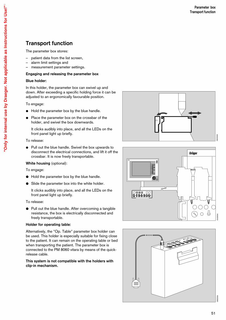
Transport functionThe parameter box stores:
– patient data from the list screen,– alarm limit settings and – measurement parameter settings.
Engaging and releasing the parameter box
Blue holder:
In this holder, the parameter box can swivel up anddown. After exceeding a specific holding force it can beadjusted to an ergonomically favourable position.
To engage:
Hold the parameter box by the blue handle.
Place the parameter box on the crossbar of theholder, and swivel the box downwards.
It clicks audibly into place, and all the LEDs on thefront panel light up briefly.
To release:
Pull out the blue handle. Swivel the box upwards todisconnect the electrical connections, and lift it off thecrossbar. It is now freely transportable.
White housing (optional):
To engage:
Hold the parameter box by the blue handle.
Slide the parameter box into the white holder.
It clicks audibly into place, and all the LEDs on thefront panel light up briefly.
To release:
Pull out the blue handle. After overcoming a tangibleresistance, the box is electrically disconnected andfreely transportable.
Holder for operating table:
Alternatively, the "Op. Table" parameter box holder canbe used. This holder is especially suitable for fixing closeto the patient. It can remain on the operating table or bedwhen transporting the patient. The parameter box isconnected to the PM 8060 vitara by means of the quick-release cable.
This system is not compatible with the holders withclip-in mechanism.
51
Parameter boxTransport function
0662
9094
D
D
1-2--
Stop
0242
9094
0982
9094
"On
ly f
or
inte
rnal
use
by
Dra
eger
. No
t ap
plic
able
as
Inst
ruct
ion
s fo
r U
se!"

Data transfer
As soon as the parameter box has clicked into place, it exchanges your data with the system monitor. Themonitor performs as programmed in »Standby« (seePage 32).
A complete list of the transported data is given in »Technical Data« on page 89.
Fully automatic procedureThe advisory message »data being transferred asrequested« is displayed.
After about 12 seconds, the new configuration isactive. No user intervention is required.
Semi-automatic procedureThe transport menu appears, as preconfigured by theuser in »Standby«.
If the monitoring requirements have changed in themeantime, the user can intervene in the data transferand modify settings in the same way as for theconfiguration in »Standby«.
The data transfer can of course also be confirmedunchanged after checking the display.
Press the rotary control to confirm these settings. All parameter box functions will then be activated afterabout 12 seconds.
List intervals
If you opt for list data transfer in the semi-automaticprocedure, you can now select the intervals.
A (monitoring) interval is the time between the engage-ment (connection) and release (disconnection) of theparameter box.
In the list screen, each interval is displayed on a separateline and marked »start interval« and »end interval«.
Parameter boxTransport function
52
List from interval:
Date time
every session
03 04-10 16:33/17:3002 04-10 17:32/17:4201 04-10 17:32/17:42
10:3400:00
01-10-96
standard screen - adultAdvisory:Caution:Warning:
1. ECGII
1mV
ART
CVP
Pleth
65pulse def. 0 ST + 0.05
122/ 89(100)
ARTiBP 1
4.5mean
CVP
99pulse 65
pulse 65
15min M (102)
SysmmHgDia
SpO2
122/ 89NiBP
36.8 37.2T1 T2 °C
iBP 2
160
10
80
0
alarminfo
timerstart
Select a menu position. Please confirm !Change the settings. Please confirm again !
The patient is newfor the:monitor yes noparameter-box yes no
HR/Pulse (ECG)
0682
9094
0502
9094
"On
ly f
or
inte
rnal
use
by
Dra
eger
. No
t ap
plic
able
as
Inst
ruct
ion
s fo
r U
se!"
ECG/Heart rate
ECG in the operating theatre
The following measures are necessary to ensure aneffective ECG, reliable heart rate calculations and patientsafety:
– Only use ECG leads with HF protection for HF surgery.
– Never use ECG needle electrodes in the operatingtheatre when an electro-surgical unit is being used!
– The ECG electrodes must be positioned as far awayas possible from the area of surgery and from theneutral electrode of the electro-surgery equipment.
– The ECG electrodes must lie as close together aspossible.
– Avoid looping the ECG leads and crossing or routingthem in parallel to electro-surgery leads.
– Deactivate pacemaker pulse detection.
– Activate the filter.
– Conductive parts of the electrodes, including theneutral electrode, must not touch other conductiveparts, including earth.
Pacemaker pulse detection
The pacemaker pulse detection must be activated if thepatient has a pacemaker (see page 24).
The heart rate is normally only calculated on the basis ofthe ECG complex and not on the basis of the pacemakerpulse.
Particular care must be taken in the case of pace-maker patients, since the pacemaker pulses may bemistaken for ventricular complexes. In such a case,calculation of the heart rate would be continued evenin the absence of an ECG!
The following points must also be noted:
– The R-waves of the ECG must be greater than0.5 mV in order to ensure reliable functioning. If this isnot the case, the ECG lead must be changed or theECG electrodes repositioned!
– Deactivate pacemaker pulse detection if it is notneeded.
– Deactivate pacemaker pulse detection in theoperating theatre when using electro surgery equipment.
53
Parameter boxECG/Heart rate
"On
ly f
or
inte
rnal
use
by
Dra
eger
. No
t ap
plic
able
as
Inst
ruct
ion
s fo
r U
se!"

Applying electrodes
– Carefully prepare the areas of skin to which theelectrodes are to be applied.
– The electrodes should be positioned in areas in whichpatient movement will not have a negative effect onthe ECG (i.e. not on top of muscles if possible).
– Appropriate points of contact for the electrodes whenusing 3, 4 or 5 electrodes can be seen from thediagrams alongside.
Abbreviations used in the diagrams:Rd = Red electrodeYe = Yellow electrodeGn = Green electrodeBl = Black (neutral) electrode
Figures 1 and 2Points of contact when using three ECG electrodes.
The contact points illustrated in Figure 1 are alsosuitable for monitoring chest ventilation (abdomenventilation can also be clearly determined if the yellowelectrode is applied to the lower costal arch). Thecontact points in Figure 2 are suitable for monitoringboth chest and abdomen ventilation.
Figure 3Points of contact when using 4 or 5 electrodes (e.g. for S-T segment analysis).
The fifth lead (V-lead) is not shown in the diagram.
Connect the end of the ECG lead with the ECGelectrodes to the patient and the other end to theparameter box (colour coded red).
ECG Display
1 The ECG of the desired derivation is displayed onscreen as defined in the configuration menu.
2 The heart rate is displayed after about 60 seconds.
If no ECG signal is present, the pulse value isdisplayed. The signal source is indicated in brackets,in the following order of priority:
ECG,SpO2,iBP 1 andiBP 2.
The iBP sources do not generate a pulse tone.
Parameter boxECG/Heart rate
54
Ye
Rd
YeBl
Rd Ye
BlGn
Rd
Bl
Figure 2
g dAUTO
Start
StopPunct.
Act.
→ 0 ← → 0 ←
10:3400:00
01-10-96
standard screen - adultAdvisory:Caution:Warning:
65pulse def. 0 ST + 0.05
122/ 89(100)
ARTiBP 1
4.5mean
CVP
99pulse 65
pulse 65
15min M (102)
SysmmHgDia
SpO2
122/ 89NiBP
36.8 37.2T1 T2 °C
iBP 2
auto setlimits
alarminfo
screenconfig.
para-meter
timerstart
limits
config.
1. ECGII
1mV
Pleth
ART
CVP
130
10
80
0
HR/Pulse (ECG)
Figure 1
Figure 3
2
0702
9094
0702
9094
0702
9094
0712
9094
0142
9094
1
Ye
"On
ly f
or
inte
rnal
use
by
Dra
eger
. No
t ap
plic
able
as
Inst
ruct
ion
s fo
r U
se!"

Adjusting settings
Press the »Parameter« softkey.The menu for setting the parameters is displayed.
Move the cursor frame to »ECG« with the rotarycontrol and press to confirm.
function on / offActivates and deactivates the ECG measur-ing function.
number of leads3 / 5The cable type to be used is defined here.
If an ECG cable with 3 leads is used, leads1, 2 and 3 are available and only one ECGmay be displayed. The options for a 2ndand 3rd ECG are cancelled.
The error message »electrode« appears if acable with four or five leads is selected butonly three electrodes are applied.
derivation 1 / 2 / 3 orI / II / III / aVR / aVL / aVF / VThe choice of derivations to be displayed isselected here, separately for the 1st, 2ndand 3rd ECG.
Amplitude 4 / 2 / 1 / 0.5 / 0.25Sets the ECG amplitude in mV/cm on themonitor, with reference to the reference barto the left of the ECG graph.
filter on / off»on« yields an extremely stable ECGwithout interference.»off« yields an ECG with high frequencyresolution, but less stable.
pacemaker on / offActivates and deactivates pacemaker pulsedetection.
Pacemaker pulses are enlargeddisproportionately when this function isactivated (not taken into account whencalculating the heart rate).
pulse deficit indicationon/offActivates and deactivates the pulse deficitindication derived from the heart rate andSpO2 pulse.
55
Parameter boxECG/Heart rate
ECG
function on off
numberof leads 3 5
1.ECG2.ECG 3.ECG
derivation
ST-segmentanalysis on off
pulse deficit indication on off
pacemaker on off
filter on off
amplitude 2
I IIIII
10:3400:00
01-10-96
standard screen - adultAdvisory:Caution:Warning:
65pulse def. 0 ST + 0.05
122/ 89(100)
ARTiBP 1
4.5mean
CVP
94pulse 65
pulse 65
SpO2
iBP 2
auto setlimits
alarminfo
para-meter
timerstart
limits
1. ECG II
1mV
Pleth
iBP 1 ART
iBP 2 CVP
140
1060
0
ECG
NiBP
iBP 1
iBP 2
SpO2 / Pleth
Resp.
Select the required parameter and confirm !
15min M (102)
SysmmHgDia
122/ 89NiBP
36.8 37.2T1 T2 °C
HR/Pulse (ecg)
0722
9094
0732
9094
"On
ly f
or
inte
rnal
use
by
Dra
eger
. No
t ap
plic
able
as
Inst
ruct
ion
s fo
r U
se!"
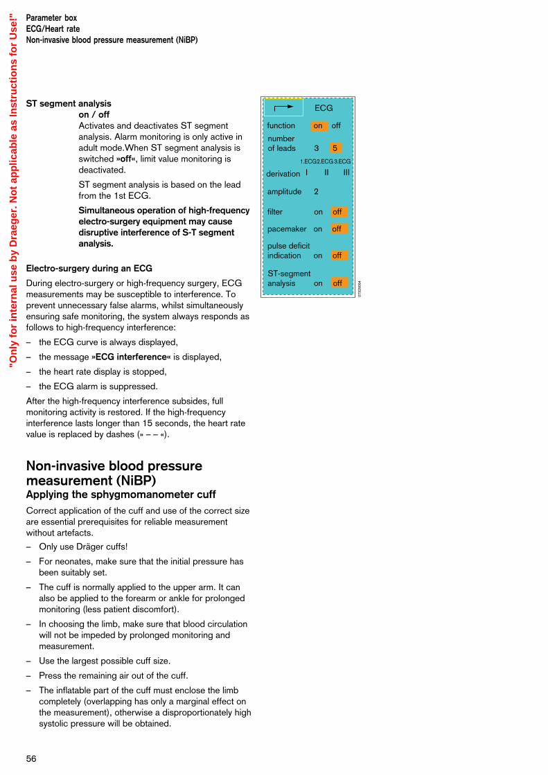
ST segment analysison / offActivates and deactivates ST segmentanalysis. Alarm monitoring is only active inadult mode.When ST segment analysis isswitched »off«, limit value monitoring isdeactivated.
ST segment analysis is based on the leadfrom the 1st ECG.
Simultaneous operation of high-frequencyelectro-surgery equipment may causedisruptive interference of S-T segmentanalysis.
Electro-surgery during an ECG
During electro-surgery or high-frequency surgery, ECGmeasurements may be susceptible to interference. Toprevent unnecessary false alarms, whilst simultaneouslyensuring safe monitoring, the system always responds asfollows to high-frequency interference:
– the ECG curve is always displayed,
– the message »ECG interference« is displayed,
– the heart rate display is stopped,
– the ECG alarm is suppressed.
After the high-frequency interference subsides, fullmonitoring activity is restored. If the high-frequencyinterference lasts longer than 15 seconds, the heart ratevalue is replaced by dashes (» – – «).
Non-invasive blood pressuremeasurement (NiBP)Applying the sphygmomanometer cuffCorrect application of the cuff and use of the correct sizeare essential prerequisites for reliable measurementwithout artefacts.
– Only use Dräger cuffs!
– For neonates, make sure that the initial pressure hasbeen suitably set.
– The cuff is normally applied to the upper arm. It canalso be applied to the forearm or ankle for prolongedmonitoring (less patient discomfort).
– In choosing the limb, make sure that blood circulationwill not be impeded by prolonged monitoring andmeasurement.
– Use the largest possible cuff size.
– Press the remaining air out of the cuff.
– The inflatable part of the cuff must enclose the limbcompletely (overlapping has only a marginal effect onthe measurement), otherwise a disproportionately highsystolic pressure will be obtained.
Parameter boxECG/Heart rateNon-invasive blood pressure measurement (NiBP)
56
ECG
function on off
numberof leads 3 5
1.ECG2.ECG 3.ECG
derivation
ST-segmentanalysis on off
pulse deficit indication on off
pacemaker on off
filter on off
amplitude 2
I IIIII
0732
9094
"On
ly f
or
inte
rnal
use
by
Dra
eger
. No
t ap
plic
able
as
Inst
ruct
ion
s fo
r U
se!"
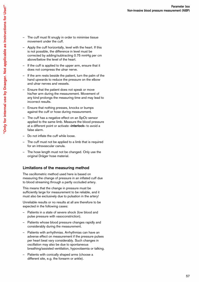
– The cuff must fit snugly in order to minimise tissuemovement under the cuff.
– Apply the cuff horizontally, level with the heart. If thisis not possible, the difference in level must becorrected by adding/subtracting 0.75 mmHg per cmabove/below the level of the heart.
– If the cuff is applied to the upper arm, ensure that itdoes not compress the ulnar nerve.
– If the arm rests beside the patient, turn the palm of thehand upwards to reduce the pressure on the elbowand ulnar nerves and vessels.
– Ensure that the patient does not speak or movehis/her arm during the measurement. Movement ofany kind prolongs the measuring time and may lead toincorrect results.
– Ensure that nothing presses, knocks or bumpsagainst the cuff or hose during measurement.
– The cuff has a negative effect on an SpO2 sensorapplied to the same limb. Measure the blood pressureat a different point or activate »interlock« to avoid afalse alarm.
– Do not inflate the cuff while loose.
– The cuff must not be applied to a limb that is requiredfor an intravascular canula.
– The hose length must not be changed. Only use theoriginal Dräger hose material.
Limitations of the measuring method
The oscillometric method used here is based onmeasuring the change of pressure in an inflated cuff dueto blood streaming through a partly occluded artery.
This means that the change in pressure must besufficiently large for measurement to be reliable, and itmust also be exclusively due to pulsation in the artery!
Unreliable results or no results at all are therefore to beexpected in the following cases:
– Patients in a state of severe shock (low blood andpulse pressure with vasoconstriction).
– Patients whose blood pressure changes rapidly andconsiderably during the measurement.
– Patients with arrhythmias. Arrhythmias can have anadverse effect on measurement if the pressure pulsesper heart beat vary considerably. Such changes inoscillation may also be due to spontaneousbreathing/assisted ventilation, hypovolaemia or talking.
– Patients with conically shaped arms (choose adifferent site, e.g. the forearm or ankle).
57
Parameter boxNon-invasive blood pressure measurement (NiBP)
"On
ly f
or
inte
rnal
use
by
Dra
eger
. No
t ap
plic
able
as
Inst
ruct
ion
s fo
r U
se!"
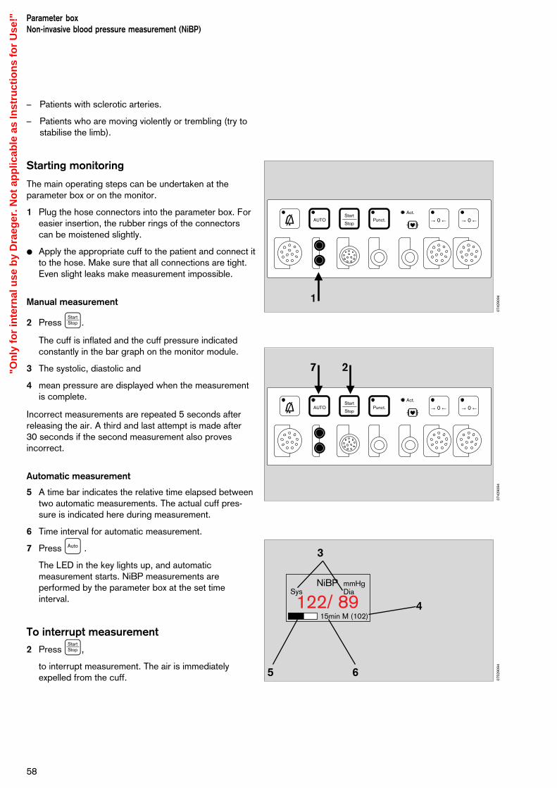
– Patients with sclerotic arteries.
– Patients who are moving violently or trembling (try tostabilise the limb).
Starting monitoring
The main operating steps can be undertaken at theparameter box or on the monitor.
1 Plug the hose connectors into the parameter box. Foreasier insertion, the rubber rings of the connectorscan be moistened slightly.
Apply the appropriate cuff to the patient and connect itto the hose. Make sure that all connections are tight.Even slight leaks make measurement impossible.
Manual measurement
2 Press ‚.
The cuff is inflated and the cuff pressure indicatedconstantly in the bar graph on the monitor module.
3 The systolic, diastolic and
4 mean pressure are displayed when the measurementis complete.
Incorrect measurements are repeated 5 seconds afterreleasing the air. A third and last attempt is made after 30 seconds if the second measurement also provesincorrect.
Automatic measurement
5 A time bar indicates the relative time elapsed betweentwo automatic measurements. The actual cuff pres-sure is indicated here during measurement.
6 Time interval for automatic measurement.
7 Press ¡ .
The LED in the key lights up, and automaticmeasurement starts. NiBP measurements areperformed by the parameter box at the set timeinterval.
To interrupt measurement
2 Press ‚,
to interrupt measurement. The air is immediatelyexpelled from the cuff.
Parameter boxNon-invasive blood pressure measurement (NiBP)
58
g dAUTO
Start
StopPunct.
Act.
→ 0 ← → 0 ←
1
g dAUTO
Start
StopPunct.
Act.
→ 0 ← → 0 ←
15min M (102)
SysmmHgDia
122/ 89NiBP
3
5 6
27
4
0742
9094
0742
9094
0752
9094
"On
ly f
or
inte
rnal
use
by
Dra
eger
. No
t ap
plic
able
as
Inst
ruct
ion
s fo
r U
se!"

Adjusting settings
Press the softkey »Parameter«.
Move the cursor frame to »NiBP« with the rotarycontrol and press to confirm.
The menu for setting the measurement parameters isdisplayed.
Auto on / offActivates automatic measurements at thespecified time intervals.
punction start / stopStarts and stops the inflation process forconstricting the venous blood flow. Thepressure is released automatically after 2 minutes.
measurementStart / Stop / Turbo
»Start« Starts a manual measurement outside theautomatic time interval.
»Stop« Ends a measurement.
Or press ‚ on the parameter box.
»Turbo« Five simplified measurements in fiveminutes. Can also be interrupted immediately by»Stop«.
time interval 2 / 3 / 5 / 10 / 15 / 20 / 30 / 60Selects the time interval for automaticmeasurement in minutes. A manuallytriggered measurement between twoautomatic measurements does not affectthe starting time for the next automaticmeasurement.
active alarms sys / diaDetermines whether the systolic or diastolicpressure is to be monitored.
initial pressure numerical(separate for adults and neonates)Sets the initial inflation pressure for themeasurement.
punction pressurenumerical(separate for adults and neonates)Sets the punction pressure in the cuff.
Change by turning the rotary control. Con-firm the new value by pressing the control.
59
Parameter boxNon-invasive blood pressure measurement (NiBP)
10:3400:00
01-10-96 Select the required parameter and confirm !
standard screen - adultAdvisory:Caution:Warning:
1. ECGII
1mV
ART
CVP
Pleth
65pulse def. 0 ST + 0.05
122/ 89(100)
ARTiBP 1
4.5mean
CVP
99pulse 65
pulse 65
15min M (102)
SysmmHgDia
SpO2
122/ 89NiBP
36.8 37.2T1 T2 °C
iBP 2
130
10
80
0
auto setlimits
alarminfo
para-meter
timerstart
ECG
NiBP
iBP 1
iBP 2
SpO2 / Pleth
Resp.
HR/Pulse (ECG)
NiBP
auto on off
punction Start Stop
measure Start Stop Turbo
time interval 15 min
active alarms sys dia
initial pressure 180 mmHg
punction pressure 40 mmHg
units mmHg kPa
interlock:
NiBP-SpO2 on off
NiBP-iBP on off
0762
9094
0732
9094
"On
ly f
or
inte
rnal
use
by
Dra
eger
. No
t ap
plic
able
as
Inst
ruct
ion
s fo
r U
se!"
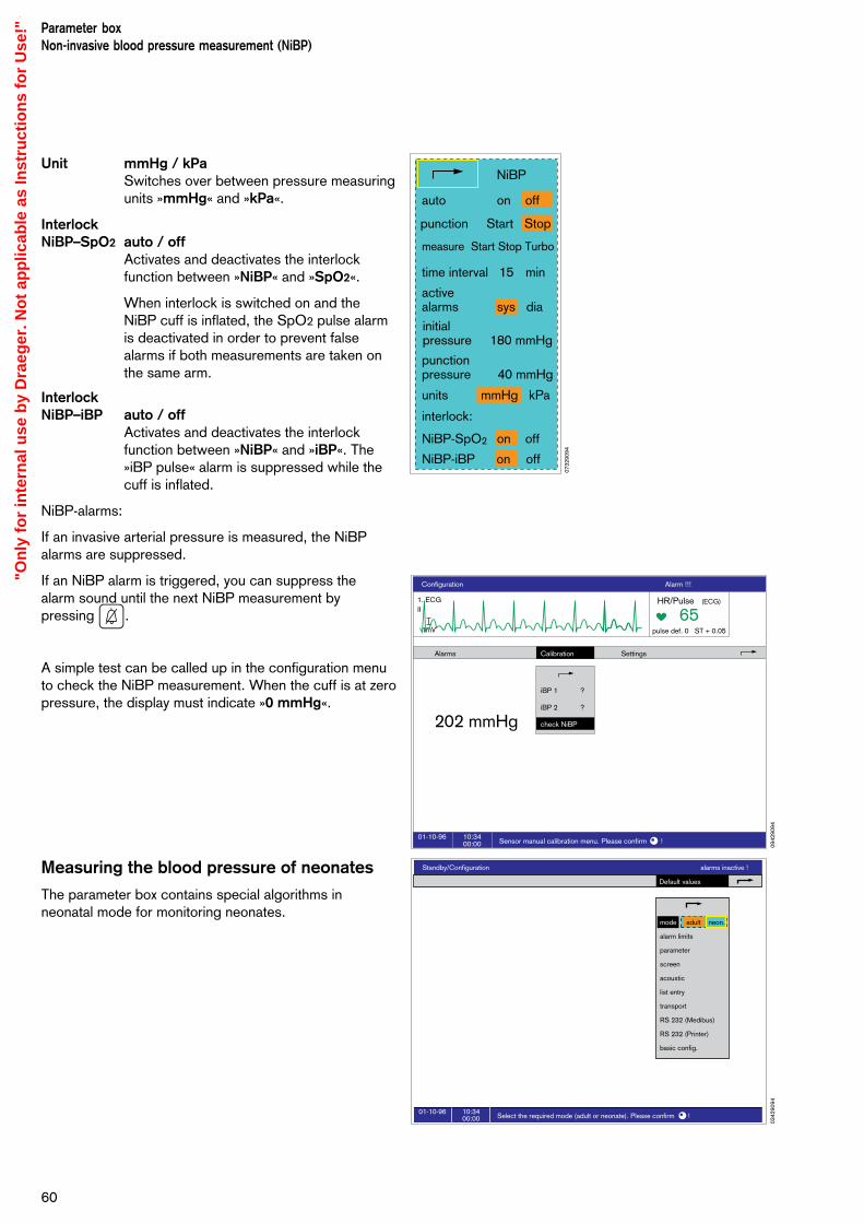
Unit mmHg / kPaSwitches over between pressure measuringunits »mmHg« and »kPa«.
InterlockNiBP–SpO2 auto / off
Activates and deactivates the interlockfunction between »NiBP« and »SpO2«.
When interlock is switched on and theNiBP cuff is inflated, the SpO2 pulse alarmis deactivated in order to prevent falsealarms if both measurements are taken onthe same arm.
InterlockNiBP–iBP auto / off
Activates and deactivates the interlockfunction between »NiBP« and »iBP«. The»iBP pulse« alarm is suppressed while thecuff is inflated.
NiBP-alarms:
If an invasive arterial pressure is measured, the NiBPalarms are suppressed.
If an NiBP alarm is triggered, you can suppress the alarm sound until the next NiBP measurement by pressing G.
A simple test can be called up in the configuration menuto check the NiBP measurement. When the cuff is at zeropressure, the display must indicate »0 mmHg«.
Measuring the blood pressure of neonates
The parameter box contains special algorithms inneonatal mode for monitoring neonates.
Parameter boxNon-invasive blood pressure measurement (NiBP)
60
Configuration Alarm !!!
10:3400:00
01-10-96Sensor manual calibration menu. Please confirm !
Alarms
202 mmHg
Settings
1. ECGII
1mV
65pulse def. 0 ST + 0.05
HR/Pulse (ECG)
Calibration
iBP 1
iBP 2
check NiBP
?
?
0942
9094
NiBP
auto on off
punction Start Stop
measure Start Stop Turbo
time interval 15 min
active alarms sys dia
initial pressure 180 mmHg
punction pressure 40 mmHg
units mmHg kPa
interlock:
NiBP-SpO2 on off
NiBP-iBP on off
0732
9094
Standby/Configuration alarms inactive !
10:3400:00
01-10-96Select the required mode (adult or neonate). Please confirm !
Default values
mode adult neon.
alarm limits
parameter
screen
acoustic
list entry
transport
RS 232 (Medibus)
RS 232 (Printer)
basic config.
0342
9094
"On
ly f
or
inte
rnal
use
by
Dra
eger
. No
t ap
plic
able
as
Inst
ruct
ion
s fo
r U
se!"

Invasive blood pressure (iBP)
Starting the monitoring of invasive bloodpressure
The settings and functions of the channels areidentical and are therefore described only once below.
For intracranial and intracardial operations, anearthing cable must first be connected forequipotential bonding between the ground stud on theback of the device (marked P ) and the groundconnection in the operating theatre.
Select the pressure transducer type in the standbyconfiguration menu (see page 25 »iBP channels«).
Connect the pressure transducer to the parameterbox (colour-coded grey).
Connect the infusion system and catheter/canula tothe transducer. Eliminate any air bubbles in thecatheter/transducer system, as they can impairmeasurement.
Apply the pressure transducer level with the heart.
If necessary, wait until the pressure transducer haswarmed up.
Connect the transducer dome to the catheter/infusionsystem, and open it to atmospheric pressure.
Calibrating the sensors Press the »parameter« softkey.
Move the cursor frame to »iBP 1« or »iBP 2« byturning the rotary control, and confirm by pressing thecontrol.
Move the cursor frame to »calibrate« by turning therotary control, and confirm by pressing the control.The system then enquires whether the sensor hasbeen exposed to atmospheric pressure.
Open the transducer dome and confirm by pressingthe rotary control.
The clock symbol u appears during the calibrationprocess. A tick () then appears behind the function.
Close the transducer dome and reopen theconnection to the catheter/infusion system; thepressure trace and pressure values are displayed.
Or on the parameter box:
Press the zero alignment key ≠ of the correspon-ding sensor twice; a tick () appears behind themenu item on the monitor.
If a fault occurs during zero alignment, a questionmark (?) appears after the menu item. The message»CAL?« is displayed instead of the measured values,or the LED in the ≠ key flashes.
61
Parameter boxInvasive blood pressure (iBP)
g dAUTO
Start
StopPunct.
Act.
→ 0 ← → 0 ←
10:3400:00
01-10-96 Select the required parameter and confirm !
standard screen - adultAdvisory:Caution:Warning:
1. ECGII
1mV
ART
CVP
Pleth
65pulse def. 0 ST + 0.05
122/ 89(100)
ARTiBP 1
4.5mean
CVP
99pulse 65
pulse 65
15min M (102)
SysmmHgDia
SpO2
122/ 89NiBP
36.8 37.2T1 T2 °C
iBP 2
130
10
80
0
auto setlimits
alarminfo
para-meter
timerstart
ECG
NiBP
iBP 1
iBP 2
SpO2 / Pleth
Resp.
HR/Pulse (ECG)
g dAUTO
Start
StopPunct.
Act.
→ 0 ← → 0 ←
0782
9094
0792
9094
0772
9094
"On
ly f
or
inte
rnal
use
by
Dra
eger
. No
t ap
plic
able
as
Inst
ruct
ion
s fo
r U
se!"

Changing settings
Press the »parameter« softkey.
Move the cursor frame to »iBP« by turning the rotarycontrol, and press to confirm.
The menu for setting the parameters is displayed.
Setting functions
function on / offActivates and deactivates the iBP measuring function.
site The names of the catheter sites areprogrammed in combination with thesuitable curve amplitude, the displayarrangement for systolic, diastolic and/ormean pressure, the alarm limits and thefilter function.
The functions are automatically activated on selecting a site designation. The samedesignation cannot be used for both iBP 1and iBP 2.
ART Arterial
Aorta Aorta
A.Pulm Pulmonary artery
CVP Central venous pressure
ICP Intracranial pressure
? any other site
active alarms sys / dia
Selects whether the systolic »sys« ordiastolic »dia« is used for monitoring.
graph abs / morph
Selects the type of graph.
– absolute graph, with reference to the zeropressure (= value of the bottom reference line). The scale of the upper reference linecan be varied.or
– morphological curve. This graph is auto-matically adjusted to the full height (amplitude) of the trace. With this method,manual scale adjustment is not possible.
Parameter boxInvasive blood pressure (iPB)
62
iBP 1
function on off
location ART
activealarms sys dia
graph absol. morph.
amplitude 160 mmHg
pulse on off
calibrate u
10:3400:00
01-10-96 Select the required parameter and confirm !
standard screen - adultAdvisory:Caution:Warning:
1. ECGII
1mV
ART
CVP
Pleth
65pulse def. 0 ST + 0.05
122/ 89(100)
ARTiBP 1
4.5mean
CVP
99pulse 65
pulse 65
15min M (102)
SysmmHgDia
SpO2
122/ 89NiBP
36.8 37.2T1 T2 °C
iBP 2
130
10
80
0
auto setlimits
alarminfo
para-meter
timerstart
ECG
NiBP
iBP 1
iBP 2
SpO2 / Pleth
Resp.
HR/Pulse (ECG)
0792
9094
0732
9094
"On
ly f
or
inte
rnal
use
by
Dra
eger
. No
t ap
plic
able
as
Inst
ruct
ion
s fo
r U
se!"
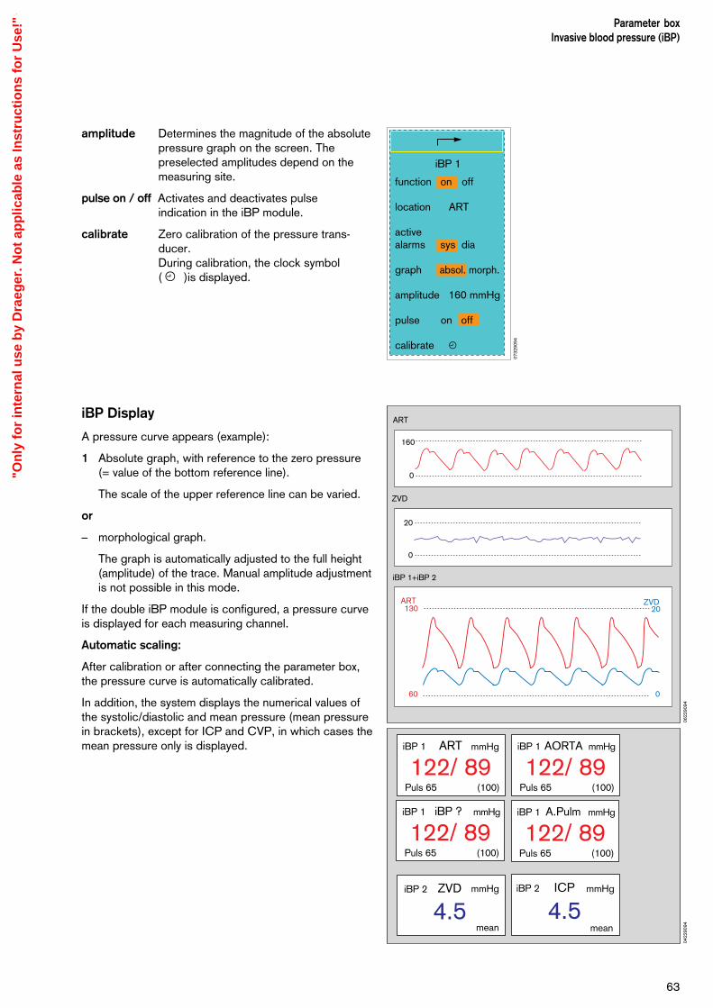
amplitude Determines the magnitude of the absolute pressure graph on the screen. The preselected amplitudes depend on the measuring site.
pulse on / off Activates and deactivates pulseindication in the iBP module.
calibrate Zero calibration of the pressure trans-ducer. During calibration, the clock symbol ( u )is displayed.
iBP Display
A pressure curve appears (example):
1 Absolute graph, with reference to the zero pressure(= value of the bottom reference line).
The scale of the upper reference line can be varied.
or
– morphological graph.
The graph is automatically adjusted to the full height(amplitude) of the trace. Manual amplitude adjustmentis not possible in this mode.
If the double iBP module is configured, a pressure curveis displayed for each measuring channel.
Automatic scaling:
After calibration or after connecting the parameter box,the pressure curve is automatically calibrated.
In addition, the system displays the numerical values ofthe systolic/diastolic and mean pressure (mean pressurein brackets), except for ICP and CVP, in which cases themean pressure only is displayed.
63
Parameter boxInvasive blood pressure (iBP)
ART
ZVD
160
0
20
0
iBP 1+iBP 2
60 0
ART130
ZVD20
mmHg mmHg
122/ 89(100)
ARTiBP 1
Puls 65
122/ 89(100)
AORTAiBP 1
Puls 65
mmHg
122/ 89(100)
A.PulmiBP 1
Puls 65
mmHg
122/ 89(100)
iBP ?iBP 1
Puls 65
mmHg mmHg
4.5mean
ZVDiBP 2 iBP 2
4.5mean
ICP
0622
9094
0422
9094
iBP 1
function on off
location ART
activealarms sys dia
graph absol. morph.
amplitude 160 mmHg
pulse on off
calibrate u
0732
9094
"On
ly f
or
inte
rnal
use
by
Dra
eger
. No
t ap
plic
able
as
Inst
ruct
ion
s fo
r U
se!"
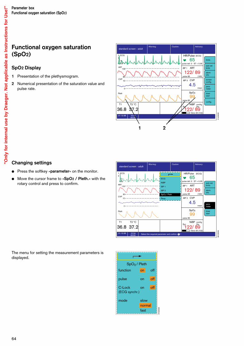
Functional oxygen saturation(SpO2)
SpO2 Display
1 Presentation of the plethysmogram.
2 Numerical presentation of the saturation value andpulse rate.
Changing settings
Press the softkey »parameter« on the monitor.
Move the cursor frame to »SpO2 / Pleth.« with therotary control and press to confirm.
The menu for setting the measurement parameters isdisplayed.
Parameter boxFunctional oxygen saturation (SpO2)
64
10:3400:00
01-10-96 Select the required parameter and confirm !
standard screen - adultAdvisory:Caution:Warning:
1. ECGII
1mV
ART
CVP
Pleth
65pulse def. 0 ST + 0.05
122/ 89(100)
ARTiBP 1
4.5mean
CVP
99pulse 65
pulse 65
15min M (102)
SysmmHgDia
SpO2
122/ 89NiBP
36.8 37.2T1 T2 °C
iBP 2
130
10
80
0
auto setlimits
alarminfo
para-meter
timerstart
ECG
NiBP
iBP 1
iBP 2
SpO2 / Pleth
Resp.
HR/Pulse (ECG)
10:3400:00
01-10-96
standard screen - adultAdvisory:Caution:Warning:
65pulse def. 0 ST + 0.05
122/ 89(100)
ARTiBP 1
4.5mean
CVP
99pulse 65
pulse 65
15min M (102)
SysmmHgDia
SpO2
122/ 89NiBP
36.8 37.2T1 T2 °C
iBP 2
auto setlimits
alarminfo
screenconfig.
para-meter
timerstart
limits
config.
1. ECGII
1mV
Pleth
ART
CVP
130
10
80
0
HR/Pulse (ECG)
21
function
pulse
C-Lock(ECG synchr.)
mode
on
on
on
slownormalfast
off
off
off
SpO2 / Pleth
0142
9095
0812
9094
0732
9094
"On
ly f
or
inte
rnal
use
by
Dra
eger
. No
t ap
plic
able
as
Inst
ruct
ion
s fo
r U
se!"

Setting functions
function on / offActivates and deactivates the measuringfunction.
pulse on / offActivates and deactivates indication of thepulse rate.
C-Lock auto / off (ECG synchr.)Activates and deactivates automatic C-Lock synchronisation. C-Lock synchronises saturation measure-ment with the ECG. (The ECG pulsetriggers SpO2 measurement). This syn-chronisation leads to better measurementresults if the patient moves or perfusion ispoor.
mode slow / normal / fastchanges the speed of measurement.
slow mode: The measured value respondsslowly to changes in oxygen saturation.Patient movement has little or no effect.
normal mode: The mode for normalconditions with relatively quiet patients.
fast mode: This mode should be usedwhenever rapid reactions are required andpatient movement is insignificant.
Safety and precautions
– For better results the sensor should not be applied tolimbs together with an arterial catheter, infusion orsphygmomanometer cuff.
– Blood circulation must not be impeded duringapplication of the sensor. If possible the measuringsite should be changed from time to time, in order toavoid pressure necroses at the measuring point.
– Protect the sensor from bright light (cover thesensor).
– Only use Nellcor sensors, and apply them asdescribed below.
– Damaged sensors must not be used.
– The adhesive strip of the oxiband sensor must bediscarded after use. Do not stretch it unduly. Neveruse two strips together.
65
Parameter boxFunctional oxygen saturation (SpO2)
99pulse 65
SpO2 %
0422
9094
function
pulse
C-Lock(ECG synchr.)
mode
on
on
on
slownormalfast
off
off
off
SpO2 / Pleth
0732
9094
"On
ly f
or
inte
rnal
use
by
Dra
eger
. No
t ap
plic
able
as
Inst
ruct
ion
s fo
r U
se!"
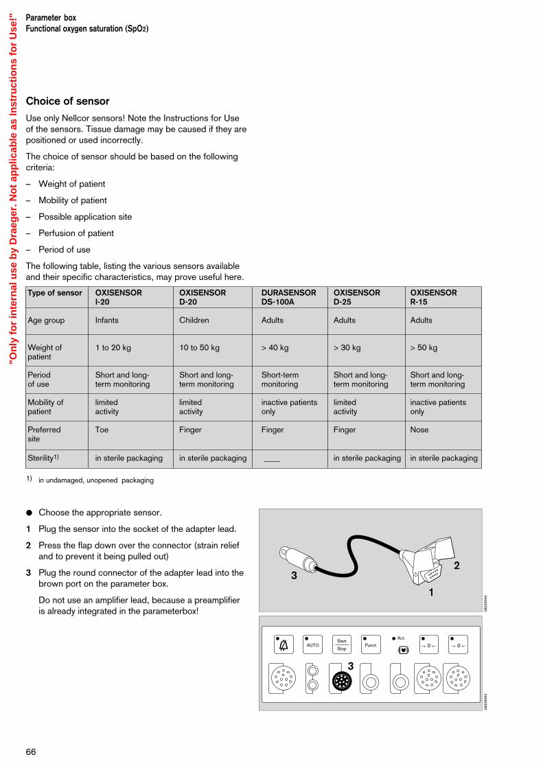
Choice of sensor
Use only Nellcor sensors! Note the Instructions for Useof the sensors. Tissue damage may be caused if they arepositioned or used incorrectly.
The choice of sensor should be based on the followingcriteria:
– Weight of patient
– Mobility of patient
– Possible application site
– Perfusion of patient
– Period of use
The following table, listing the various sensors availableand their specific characteristics, may prove useful here.
1) in undamaged, unopened packaging
Choose the appropriate sensor.
1 Plug the sensor into the socket of the adapter lead.
2 Press the flap down over the connector (strain reliefand to prevent it being pulled out)
3 Plug the round connector of the adapter lead into thebrown port on the parameter box.
Do not use an amplifier lead, because a preamplifier is already integrated in the parameterbox!
Parameter boxFunctional oxygen saturation (SpO2)
66
1
23
g dAUTO
Start
StopPunct.
Act.
→ 0 ← → 0 ←
3
0822
9094
0832
9094
Type of sensor OXISENSOR OXISENSOR DURASENSOR OXISENSOR OXISENSORI-20 D-20 DS-100A D-25 R-15
Age group Infants Children Adults Adults Adults
Weight of 1 to 20 kg 10 to 50 kg > 40 kg > 30 kg > 50 kgpatient
Period Short and long- Short and long- Short-term Short and long- Short and long-of use term monitoring term monitoring monitoring term monitoring term monitoring
Mobility of limited limited inactive patients limited inactive patientspatient activity activity only activity only
Preferred Toe Finger Finger Finger Nosesite
Sterility1) in sterile packaging in sterile packaging ____ in sterile packaging in sterile packaging
"On
ly f
or
inte
rnal
use
by
Dra
eger
. No
t ap
plic
able
as
Inst
ruct
ion
s fo
r U
se!"

Tips to avoid artefacts
Nellcor sensors only must be used, and they must becorrectly positioned to avoid the risk of measuring errorsand tissue damage.
Damaged sensors with exposed electric wires orcontacts must be withdrawn from use – danger ofelectric shock.
Adhesive strips must not be reused. They may not adhereproperly. The adhesive strips must not be stretchedunduly. Never use two adhesive strips together, as thismay lead to venous pulsation and the failure of the pulsesignal.
High intrathoracic pressure, pressure on the thorax andother consecutive impairments of the venous flow canlead to venous pulsation with failure of the pulse signal.
The pulse signal may fail in the presence of shock, lowblood pressure, severe vasoconstriction, major anaemia,hypothermia, arterial occlusion proximal to the sensor andasystolia.
In the presence of bright light sources (e.g. surgicallamps and direct sunlight) the sensor must be covered,otherwise the pulse signal may fail or inaccurate resultsmay be obtained.
The sensor should not be positioned on limbs togetherwith an arterial catheter, sphygmomanometer cuff orintravascular venous infusion: the pulse signal may fail,and measurement becomes inaccurate.
Measurement accuracy may also be reduced in the eventof significant concentrations of dyshaemoglobins, suchas carboxyhaemoglobin or methaemoglobin, as well as ofintravascular dyes, such as methylene blue.
Electrocautery can impair the measuring accuracy; theleads and sensor should therefore be positioned as faraway as possible from the electrocautery and its neutralelectrode.
Sensor performance may be impaired if the patientmoves violently, thus leading to inaccurate results. Thesensor should be applied to a different site in such casesin order to reduce the risk of artefacts due to movement.
Coupling with non-invasive pressuremeasurement
The "interlock" function should be activated if SpO2
measurement and non-invasive blood pressuremeasurement are performed simultaneously on the samearm. The interlock function prevents false alarms beinggenerated when the absence of a pulse is detectedduring NiBP measurement (see page 56).
67
Parameter boxFunctional oxygen saturation (SpO2)
Functional saturation compared withfractional saturation
Functional saturation is calculated as follows:
100 x HbO2 % SpO2 (func) = –––––––––––– %
HbO2 + Hb
Functional oxygen saturation is defined as the ratio ofoxygen-laden haemoglobin to the total quantity of haem-oglobin capable of transporting oxygen, expressed as apercentage.
Both oxygenated and reduced haemoglobin values aremeasured. Substantial amounts of dysfunctional haem-oglobins, such as carboxyhaemoglobin and methaemo-globin, are disregarded. Fractional saturation can bemeasured in a variety of ways.
The percentage fractional saturation indicates the ratio ofoxyhaemoglobin to total haemoglobin, regardless ofwhether or not the haemoglobin is available for oxygentransport. The measured dysfunctional haemoglobin isincluded.
When comparing the results obtained by different modulemanufacturers, it is important to know which method ofcalculation has been used in each case. The functionalsaturation can be calculated from the fractional saturationas follows:
Fract. Sat. x 100Funct.Sat. = ––––––––––––––––––––––––––––––––––––––––
100 - (% CO-haemoglobin + % methaemoglobin)
Comparing the measured saturation to thecalculated saturation
The oxygen saturation calculated from the partialpressure of the arterial oxygen (PaO2) may differ from thevalues actually measured. The reason may be that whencalculating the blood gas value, parameters such astemperature, pH-value, PaCO2, 2.3-DPG and foetalhaemoglobin concentration were not corrected.
SpO2 measurement
Measuring principle
The light absorption properties of oxygenated arterialblood (oxyhaemoglobin HbO2) differ from those ofunsaturated venous blood (reduced haemoglobin Hb).
O2 saturation is a logarithmic function of the irradiatedlight intensity (Lambert-Beer's law).
The effect of dyshaemoglobins such as carbon monoxidehaemoglobin HbCO and methaemoglobin MetHb isnormally negligible.
"On
ly f
or
inte
rnal
use
by
Dra
eger
. No
t ap
plic
able
as
Inst
ruct
ion
s fo
r U
se!"

Parameter boxFunctional oxygen saturation (SpO2)
68
The sensor comprises two light-emitting diodes whichalternately emit infrared light and red light with a typicalwavelength of 920 nm and 660 nm respectively. Theradiation intensity is measured by a photodetector oppo-site the diodes. The sensor is positioned on a limb inwhich the arterial blood vessels can be irradiated, suchas a finger, toe or the nose.
These two wavelengths (920 nm and 660 nm) have beenchosen because, even in the presence of slight per-fusion, they still provide meaningful absorption values forboth oxygenated and reduced blood, while at the sametime they differ significantly.
The light alternately emitted by the diodes is completelyabsorbed by the pulsating arterial blood, the skin, fingernails, muscular tissue, bones and venous blood.
Except for the pulsating arterial blood, the quantity andoptical density of the light absorbed by the othercomponents remains constant over a given unit of time.
By contrast, the arterial blood pulsating with every beat ofthe heart produces a change of tissue volume insynchronism with the pulse in the irradiated tissue,thereby causing a variation in the absorption of irradiatedlight in time with the pulse.
The light absorbed when there is no pulsating blood(during the diastole) is determined first. Thismeasurement gives the amount of light absorbed bytissue and non-pulsating blood.
Normally, the absorption value does not change duringthe pulse phase and provides a reference value for thepulsating part of the absorption.
Light-emitting diodes
Infrared light920 nm
Red light660 nm
Photodetector
20 000
10 000
5 000
1 000500
10050
10500 650 750 850 950
660 nmRed
920 nmInfrared
Reduced haemoglobin Hboxygenated haemoglobin HbO2
Wavelength nm
Abs
orpt
ion
coef
ficie
nt
The absorption is then measured after the next heartbeat,when the blood flows into the tissue. For thismeasurement, the light absorption of both wavelengthschanges, due to the pulsating arterial blood.
The graph above shows an example of the light absorbedby the blood at 660 nm (red) and 920 nm (infrared).
With increasing O2 saturation, the absorption andcorresponding pulse amplitude fall at 660 nm but rise at920 nm. Since the absorption coefficients of HbO2 andHb are known for both wavelengths, the system cancalculate the quantity of each of these two haemoglobinspresent. The quotient obtained by dividing theoxygenated haemoglobin (HbO2) by the reduced andoxygenated haemoglobin (Hb+HbO2) is termed the"functional saturation":
% SpO2 (func) = 100 x
This functional saturation refers only to the haemoglobincapable of transporting oxygen.
Dyshaemoglobins, HbCO and MetHb are normallynegligible but may affect the accuracy of the measure-ment.
Pul
se a
mpl
itude
Time (s)
at 660 nm Red
O2 saturation O2 saturation 100%
at 920 nm Infrared
Pul
se a
mpl
itude
Time (s)
HbO2
HbO2 + Hb
Abs
orpt
ion
Time (s)
Absorption byarterial bloodAbsorption byvenous blood
Absorption byother tissues(incl. skin)
0842
9094
0862
9094
0852
9094
0872
9094
"On
ly f
or
inte
rnal
use
by
Dra
eger
. No
t ap
plic
able
as
Inst
ruct
ion
s fo
r U
se!"
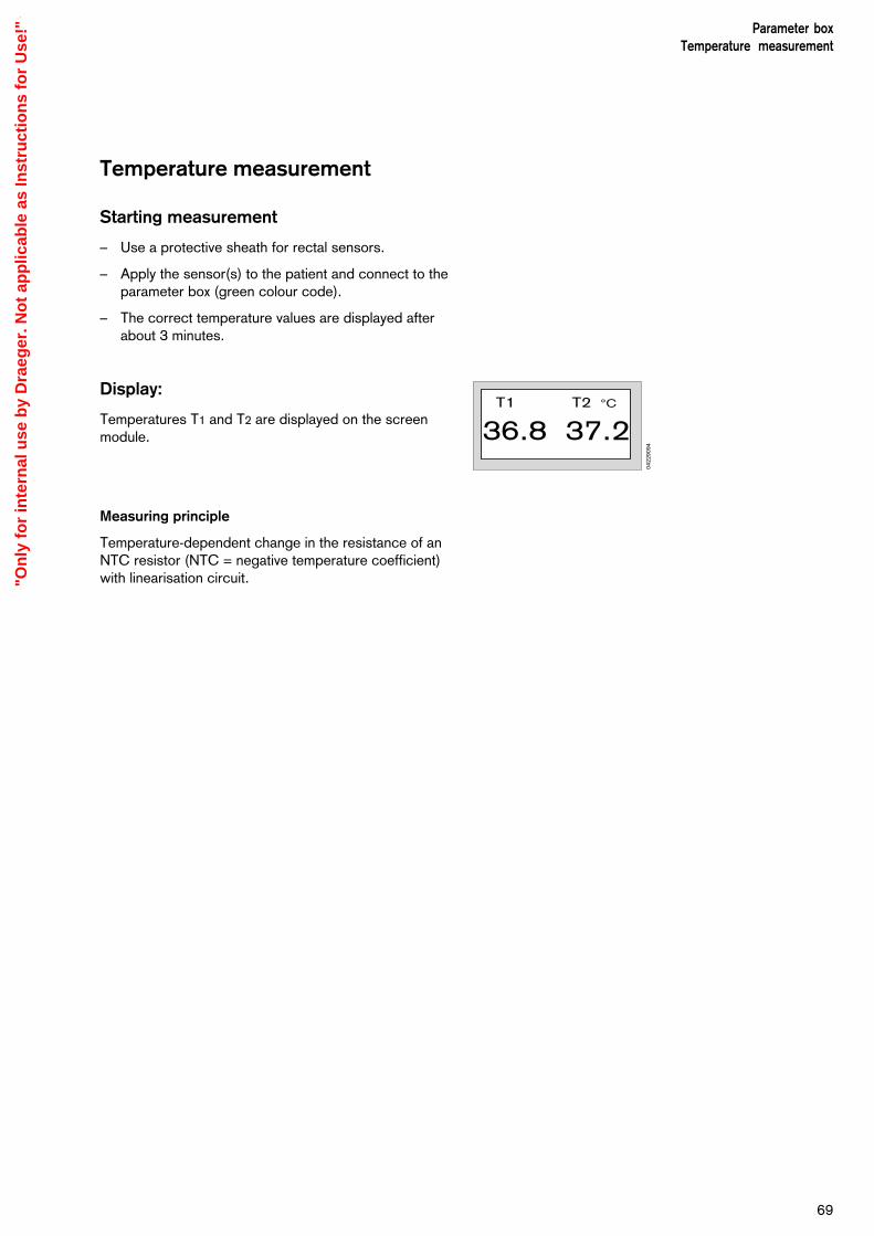
69
Parameter boxTemperature measurement
Temperature measurement
Starting measurement
– Use a protective sheath for rectal sensors.
– Apply the sensor(s) to the patient and connect to theparameter box (green colour code).
– The correct temperature values are displayed afterabout 3 minutes.
Display:
Temperatures T1 and T2 are displayed on the screenmodule.
Measuring principle
Temperature-dependent change in the resistance of anNTC resistor (NTC = negative temperature coefficient)with linearisation circuit.
36.8 37.2T1 T2 °C
0422
9094
"On
ly f
or
inte
rnal
use
by
Dra
eger
. No
t ap
plic
able
as
Inst
ruct
ion
s fo
r U
se!"

Respiration Respiration is measured and monitored (rheographically)with the red and yellow ECG electrodes.
Respiration monitoring is not possible if the greenECG cable is used (HF interference suppressed).
Starting respiration monitoring
Respiration monitoring is activated as soon as ECGmonitoring is started after switching on the Respirationfunction in the Parameters menu.
Respiration monitoring is switched OFF by default.
Cardiorespirogram
The Trend screen shows the trend curve of thecardiorespirogram (HR / RR).
Changing settings
Select the »Parameter« softkey.
Move the cursor frame to »Resp.« with the rotarycontrol and press to confirm.
The menu for setting the measurement parameters isthen displayed:
function on/offSwitches the measuring function on/off.
mode auto / manAutomatic or manual adjustment of therecording level.
amplitude 1 / 2 / 4 / 8 / 16 / 32Selects the scale of the respiration curve.The minimum size must correspond to thelength of the displayed bar.
trigger on/offActivates/deactivates the display ofrespiration recording pulses superimposedon the respiration curve (for checking thatrespiration is correctly recorded).
apnea off / 10 / 15 / 20 / 30Time interval in seconds after which anapnoea alarm is triggered in the absence ofrespiration measurement signal.
RespirationStarting respiration monitoringDisplay
70
g dAUTO
Start
StopPunct.
Act.
→ 0 ← → 0 ←
0712
9094
Resp.
function on off
mode auto man
amplitude 1 ∆E/cm
trigger on off
apnea 10 s
0382
9094
"On
ly f
or
inte
rnal
use
by
Dra
eger
. No
t ap
plic
able
as
Inst
ruct
ion
s fo
r U
se!"
71
Applying electrodes
– Please refer to the relevant instructions in the sectionon »ECG/Heart rate«.
The best results are obtained when the electrodes of the yellow and red connections are applied as far aspossible from each other on both sides of the thorax.
Respiration measurement
The breathing rate is calculated from the respirationcurve (result of impedance variations in the thorax). Oncethe curve is recorded, it provides the basis for calculatingthe respiration rate per minute. Two different measure-ment methods are applied:
Automatic mode
The recorded level of the respiration curves is auto-matically adapted to the size of the curve. In this mode,slow-acting variations in curve size do not affect thecalculation of the respiration rate. In general, this mode is preferred.
Adjustment of the recorded level to variations in curvesize is a relatively slow process. Consequently, thesystem does not respond rapidly to changes in curvesize, and no alarm can be emitted. Manual mode istherefore available for patients with a sporadically very flat respiration pattern.
Manual mode
A fixed level with a bar length (curve amplitude) of 10 mm is displayed on screen to help identify therespiration curve. All curves with a size of more than 10 mm are included in the respiration rate calculation.
Apnoea/coincidence alarm
The screen delivers an apnoea alarm if no respiration isdetected during a predefined period of time. This period(duration of apnoea before the alarm is triggered) can beprogrammed in the parameter menu (off, 10, 15, 20 and30 seconds).
The mechanical heart function can be superimposed onthe respiration curve in the form of amplitude"excursions" (deflections). In the absence of anyrespiration, these pulsations could be misinterpreted asrespiration curves. In this case, the respiration rate andheart rate would be considered roughly equal, and so anapnoea alarm would not be triggered.
The coincidence alarm, which indicates a suspectedapnoea alarm, is triggered if the values of the recordedheart rate and respiration rate are identical, to within 5%,for a period of at least 5 seconds, and if respiration is
RespirationDisplay
"On
ly f
or
inte
rnal
use
by
Dra
eger
. No
t ap
plic
able
as
Inst
ruct
ion
s fo
r U
se!"
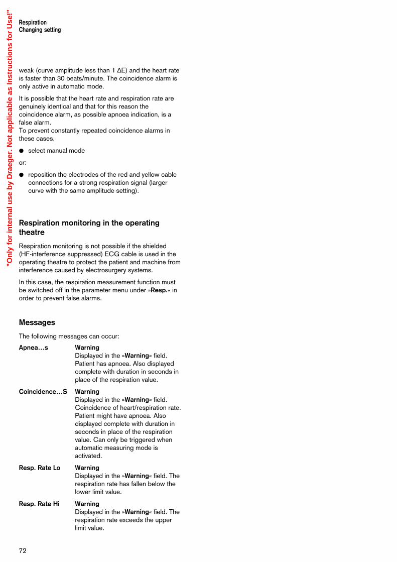
72
weak (curve amplitude less than 1 ∆E) and the heart rateis faster than 30 beats/minute. The coincidence alarm isonly active in automatic mode.
It is possible that the heart rate and respiration rate aregenuinely identical and that for this reason thecoincidence alarm, as possible apnoea indication, is afalse alarm.To prevent constantly repeated coincidence alarms inthese cases,
select manual mode
or:
reposition the electrodes of the red and yellow cableconnections for a strong respiration signal (largercurve with the same amplitude setting).
Respiration monitoring in the operatingtheatre
Respiration monitoring is not possible if the shielded (HF-interference suppressed) ECG cable is used in theoperating theatre to protect the patient and machine frominterference caused by electrosurgery systems.
In this case, the respiration measurement function mustbe switched off in the parameter menu under »Resp.« inorder to prevent false alarms.
Messages
The following messages can occur:
Apnea…s WarningDisplayed in the »Warning« field.Patient has apnoea. Also displayedcomplete with duration in seconds inplace of the respiration value.
Coincidence…S WarningDisplayed in the »Warning« field.Coincidence of heart/respiration rate.Patient might have apnoea. Alsodisplayed complete with duration inseconds in place of the respirationvalue. Can only be triggered whenautomatic measuring mode isactivated.
Resp. Rate Lo WarningDisplayed in the »Warning« field. Therespiration rate has fallen below thelower limit value.
Resp. Rate Hi WarningDisplayed in the »Warning« field. Therespiration rate exceeds the upperlimit value.
RespirationChanging setting
"On
ly f
or
inte
rnal
use
by
Dra
eger
. No
t ap
plic
able
as
Inst
ruct
ion
s fo
r U
se!"

Contents
Where messages occur ...........................................................................74Messages on the Monitor......................................................................... 75
73
TroubleshootingContents
Troubleshooting
"On
ly f
or
inte
rnal
use
by
Dra
eger
. No
t ap
plic
able
as
Inst
ruct
ion
s fo
r U
se!"

Where messages occur
Warning, caution and advisory messagesThese are the three types of message output by thesystem. They are classified in order of priority and listedalphabetically in the following tables (from page 69onwards).
User promptsappear in the bottom right-hand corner of the screen.
Display all alarms
1 Press the »alarm info« softkey.The alarm texts of all active Warnings, CautionMessages and Advisory Messages are displayed inorder of priority on the screen.
Troubleshooting
74
D
1-2--
Stop
Warning Caution Advisory
10:3400:00
01-10-96
standard screen - adultAdvisory:Caution:Warning:
36.8 37.2T1 T2 °C
auto setlimits
alarminfo
screenconfig.
para-meter
timerstart
limits
config.
1. ECGII
1mV
Pleth
ART
CVP
130
10
80
0
TEMP2 CALIB !
TEMP1 !!
SPO2 !!!
108
8290
94
0632
9094
"On
ly f
or
inte
rnal
use
by
Dra
eger
. No
t ap
plic
able
as
Inst
ruct
ion
s fo
r U
se!"

Messages on the monitor(in alphabetical order).
Alarm messages are assigned to three priority classes(alarm priority) in the monitor of the PM 8060 vitara:
– Warning symbol »!!!« Text in red field
– Caution symbol »!!« Text in yellow field
– Advisory symbol »!« Text in white field
Always check the patient's condition first, beforeexamining the machine for any possible measuringerror!
75
Troubleshooting
Messages Cause Remedy
APNEA ECG !!! Breathing/ventilation has stopped. No breathdetected by rheographic measurement.
Check condition of patient.
ASYSTOLY !!! No QRS waves have been detected in the ECGsignal in the last 6 seconds.
Check condition of patient.
BP CUFF DISC ! Cuff hose disconnected?Leak in hose or cuff?
Check conditions.Replace cuff or hose.
BP CUFF ERR ! Cuff incorrectly positioned.Background interference.Highly irregular pulse?
Check cuff position.Do not touch cuff during measurement.
CAN COM ERR Communication via CAN interface faulty. Check connections of data lead.Inform Dräger Service.
CHECK iBP1 !CHECK iBP2 !
No pulse detected during pressure measurement. Check transducer and replace ifnecessary.
COINCIDENCE ! Respiration rate and heart rate are approximatelyequal.
Check condition of patient.
COOLING 8060? ! Temperature inside machine too high. Inform Dräger Service.
DIAS iBP1 HI !!DIAS iBP2 HI !!
Diastolic pressure of the displayed channel (1 or 2)above the upper alarm limit.
Check condition of patient.Correct alarm limit if necessary.
DIAS iBP1 LO !!DIAS iBP2 LO !!
Diastolic pressure of the displayed channel (1 or 2)below the lower alarm limit.
Check condition of patient.Correct alarm limit if necessary.
ECG ARTIFACT ! The ECG signal has been disturbed by extraneousfactors. The heart rate display will be paused for 15 seconds and will then be deactivated if theinterference continues after this period.
ECG ELECTROD ! ECG electrodes disconnected for longer than 15 seconds.
Check condition of patient.Correct alarm limit if necessary.
ECG INTERFERENCE ! The ECG signal has been distorted by interferencefrom electro-surgery. The heart rate display will bepaused for 15 seconds and will then be deactivatedif the interference continues after this period.
ECG N ? ! ( !! )ECG LA ? ! ( !! )ECG LL ? ! ( !! )ECG RA ? ! ( !! )ECG V ? ! ( !! )
ECG electrodes have fallen off. Secure electrodes.
(Can be configured by Dräger-Serrvice to alarm level»Caution« with display »!!«)
"On
ly f
or
inte
rnal
use
by
Dra
eger
. No
t ap
plic
able
as
Inst
ruct
ion
s fo
r U
se!"
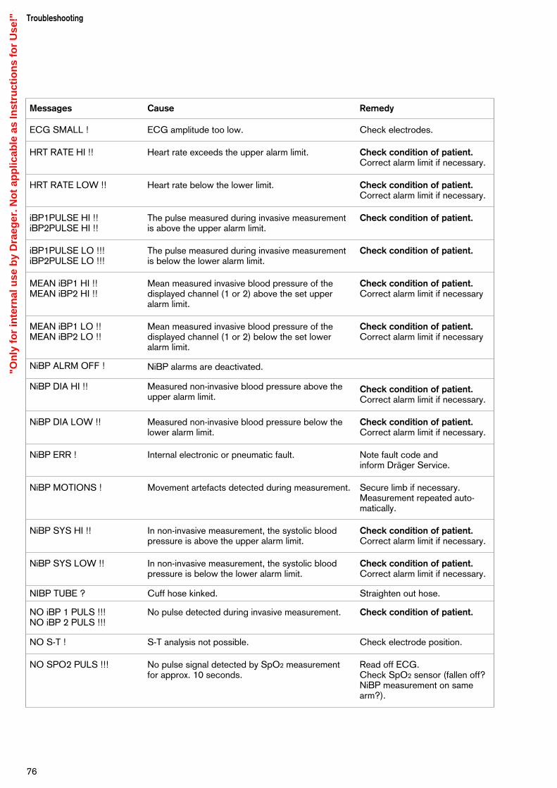
Troubleshooting
76
Messages Cause Remedy
ECG SMALL ! ECG amplitude too low. Check electrodes.
HRT RATE HI !! Heart rate exceeds the upper alarm limit. Check condition of patient.Correct alarm limit if necessary.
HRT RATE LOW !! Heart rate below the lower limit. Check condition of patient.Correct alarm limit if necessary.
iBP1PULSE HI !!iBP2PULSE HI !!
The pulse measured during invasive measurementis above the upper alarm limit.
Check condition of patient.
iBP1PULSE LO !!!iBP2PULSE LO !!!
The pulse measured during invasive measurementis below the lower alarm limit.
Check condition of patient.
MEAN iBP1 HI !!MEAN iBP2 HI !!
Mean measured invasive blood pressure of thedisplayed channel (1 or 2) above the set upperalarm limit.
Check condition of patient.Correct alarm limit if necessary
MEAN iBP1 LO !!MEAN iBP2 LO !!
Mean measured invasive blood pressure of thedisplayed channel (1 or 2) below the set loweralarm limit.
Check condition of patient.Correct alarm limit if necessary
NiBP ALRM OFF ! NiBP alarms are deactivated.
NiBP DIA HI !! Measured non-invasive blood pressure above theupper alarm limit.
Check condition of patient.Correct alarm limit if necessary.
NiBP DIA LOW !! Measured non-invasive blood pressure below thelower alarm limit.
Check condition of patient.Correct alarm limit if necessary.
NiBP ERR ! Internal electronic or pneumatic fault. Note fault code and inform Dräger Service.
NiBP MOTIONS ! Movement artefacts detected during measurement. Secure limb if necessary.Measurement repeated auto-matically.
NiBP SYS HI !! In non-invasive measurement, the systolic bloodpressure is above the upper alarm limit.
Check condition of patient.Correct alarm limit if necessary.
NiBP SYS LOW !! In non-invasive measurement, the systolic bloodpressure is below the lower alarm limit.
Check condition of patient.Correct alarm limit if necessary.
NIBP TUBE ? Cuff hose kinked. Straighten out hose.
NO iBP 1 PULS !!!NO iBP 2 PULS !!!
No pulse detected during invasive measurement. Check condition of patient.
NO S-T ! S-T analysis not possible. Check electrode position.
NO SPO2 PULS !!! No pulse signal detected by SpO2 measurementfor approx. 10 seconds.
Read off ECG.Check SpO2 sensor (fallen off?NiBP measurement on samearm?).
"On
ly f
or
inte
rnal
use
by
Dra
eger
. No
t ap
plic
able
as
Inst
ruct
ion
s fo
r U
se!"

77
Troubleshooting
Messages Cause Remedy
P-BOX ALR OF ! The parameter box alarms are deactivated.
PB 8800 COM ? ! Communication failure with parameter box 8800 Check cable connections.
RESP RATE HI !! The measured respiration rate exceeds the upperalarm limit.
Check condition of patient.
Correct alarm limit if necessary.
RESP RATE LO !! The measured respiration rate is below the loweralarm limit.
Check condition of patient.
Correct alarm limit if necessary.
RS232COM ERR ! RS 232 communication interrupted. Check connection.
S-T MV > !!! Magnitude of S-T segment exceeds the upperalarm limit.
Check condition of patient.Correct alarm limit if necessary.
SPEAKER FAIL ! No alarm sound. Speaker defective. Inform Dräger Service.
SPO2 ALRM OF ! The SpO2 alarm is deactivated.
SPO2 ERR ! SpO2 measurement faulty. Inform Dräger Service.
SPO2 HIGH !! Oxygen saturation exceeds the upper alarm limit. Check the O2 concentration inthe fresh gas.Check ventilation.
SPO2 LOW !!! Oxygen saturation below the lower alarm limit. Check ventilation.Check the O2 concentration inthe fresh gas.
SPO2 PULS HI !! The pulse rate exceeds the upper alarm limit. Check condition of patient.Correct alarm limit if necessary.
SPO2 PULS LO !!! The pulse rate has dropped below the lower alarmlimit.
Check condition of patient.
SPO2SEN DISC ! No pulse detected by the pulsoxymeter, eventhough the heart is clearly beating.
Check condition of patient(disturbed circulation?). Check that SpO2 sensor iscorrectly seated.
SYS iBP1 HI !!SYS iBP2 HI !!
In invasive measurement, the systolic bloodpressure of the displayed channel (1 or 2) is abovethe upper alarm limit.
Check condition of patient.Correct alarm limit if necessary.
SYS iBP1 LOW !!SYS iBP2 LOW !!
In invasive measurement, the systolic bloodpressure of the displayed channel (1 or 2) is belowthe lower alarm limit.
Check condition of patient.Correct alarm limit if necessary.
TEMP 1 HIGH !!TEMP 2 HIGH !!
Measured body temperature of the displayedchannel (1 or 2) is above the upper alarm limit.
Check condition of patient.Correct alarm limit if necessary.
TEMP 1 INOP !TEMP 2 INOP !
Temperature measuring function defective. Replace temperature sensor.Inform Dräger Service.
"On
ly f
or
inte
rnal
use
by
Dra
eger
. No
t ap
plic
able
as
Inst
ruct
ion
s fo
r U
se!"

Troubleshooting
78
Messages Cause Remedy
TEMP 1 LOW !!TEMP 2 LOW !!
Measured body temperature of the displayedchannel (1 or 2) is below the lower alarm limit.
Check condition of patient.Correct alarm limit if necessary.
TEMP1 CALIB !TEMP2 CALIB !
Fault found during the automatic internal accuracytest.
Inform DrägerService.
VENTR. FIBR. !!! Ventricular fibrilklation detected for longer than3 seconds.
Check condition of patient.
"On
ly f
or
inte
rnal
use
by
Dra
eger
. No
t ap
plic
able
as
Inst
ruct
ion
s fo
r U
se!"
Contents
Stripping down the machine...................................................................80
Cleaning/disinfecting..............................................................................80Active agents and methods ......................................................................80Disposing of disposable articles................................................................80Wipe-cleaning.......................................................................................... 80Disinfecting with formaldehyde vapour......................................................80Preparing the accessories........................................................................ 81Inspection intervals...................................................................................82
79
CareContents
Care
"On
ly f
or
inte
rnal
use
by
Dra
eger
. No
t ap
plic
able
as
Inst
ruct
ion
s fo
r U
se!"

Stripping down the machineDisconnect the device from the power supply, either byswitching off the anaesthetic unit or the power adapter ofthe PM 8060 vitara.
Cleaning/disinfectingCleaning/disinfecting the screen andparameter box
– Disconnect the power supply before cleaning.
– Wipe the screen and parameter box with a dampcloth and household liquid soap. Do not allow wateror other liquids to enter the device.
– Disinfect by wiping with disinfectant.
– The disinfecting method must conform to the relevantregulations and recommendations.
– Do not use corrosive detergents, scouring agentsor solvents.
Agents and methods for disinfecting,cleaning and sterilisation
Only products from the list of surface disinfectantsshould be used for disinfecting. To ensure materialcompatibility, products based on the following agentsmay be used:
– aldehydes,– alcohols and – quaternary ammonium products.
The following products are suitable:
– Bacilloform,– Buraton 10F,– Alhydex (Cidex),– Gigasept,– Liquidasept,– Halamid,– Savlon,– Hybitan,– Cetavlon– Terralin.
Follow the manufacturer's instructions.
The following products are not suitable:
– phenols,– halogen-releasing compounds,– strong organic acids and– oxygen-releasing compounds Do not use Ivisol or Edisonite.
CareStripping down the machineCleaning/disinfecting
80
Users in the Federal Republic of Germany are advised touse disinfectants specified in the current list published bythe German Society for Hygiene and Microbiology(DGHM). The DGHM list also specifies the active agentof each disinfectant.
Users in countries in which the DGHM list is not availableare advised to use the agents mentioned above.
– Do not expose the devices to gaseousdisinfectants.
– Spray-disinfecting is not recommended. If a room isdisinfected with an atomiser, the devices must becarefully covered with a piece of plastic. The devicesmust be switched off at the power switch and allowedto cool down sufficiently.
– Do not operate the devices in the presence ofdisinfectants that evaporate and form explosivemixtures. The vapour must have escaped beforethe devices are switched on again.
Disposal of disposable articlesDisposable articles and articles with limited service lifecan be disposed of as household refuse, provided thatthey have been used with non-infectious patients.
Infectious waste must be disposed of in accordancewith the applicable special regulations.
Wipe cleaningParts which can be wipe-cleaned are listed in the tablepage 82.
Use a disposable cloth moistened with disinfectantcleaner.
Note effective time – parts must only be wiped, notimmersed – do not allow liquid to seep inside themachine!
Disinfection with formaldehyde vapourThe PM 8060 vitara and the parameter box must not betreated with formaldehyde vapour!
"On
ly f
or
inte
rnal
use
by
Dra
eger
. No
t ap
plic
able
as
Inst
ruct
ion
s fo
r U
se!"
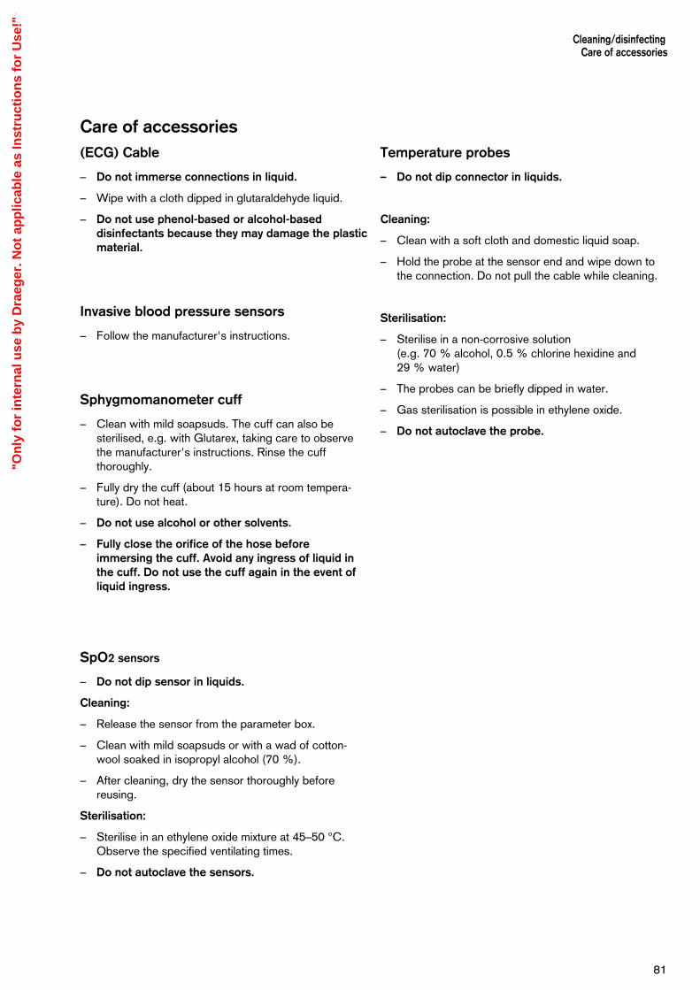
Care of accessories(ECG) Cable
– Do not immerse connections in liquid.
– Wipe with a cloth dipped in glutaraldehyde liquid.
– Do not use phenol-based or alcohol-baseddisinfectants because they may damage the plasticmaterial.
Invasive blood pressure sensors
– Follow the manufacturer's instructions.
Sphygmomanometer cuff
– Clean with mild soapsuds. The cuff can also besterilised, e.g. with Glutarex, taking care to observethe manufacturer's instructions. Rinse the cuffthoroughly.
– Fully dry the cuff (about 15 hours at room tempera-ture). Do not heat.
– Do not use alcohol or other solvents.
– Fully close the orifice of the hose beforeimmersing the cuff. Avoid any ingress of liquid inthe cuff. Do not use the cuff again in the event ofliquid ingress.
SpO2 sensors
– Do not dip sensor in liquids.
Cleaning:
– Release the sensor from the parameter box.
– Clean with mild soapsuds or with a wad of cotton-wool soaked in isopropyl alcohol (70 %).
– After cleaning, dry the sensor thoroughly beforereusing.
Sterilisation:
– Sterilise in an ethylene oxide mixture at 45–50 °C.Observe the specified ventilating times.
– Do not autoclave the sensors.
Cleaning/disinfecting Care of accessories
81
Temperature probes
– Do not dip connector in liquids.
Cleaning:
– Clean with a soft cloth and domestic liquid soap.
– Hold the probe at the sensor end and wipe down tothe connection. Do not pull the cable while cleaning.
Sterilisation:
– Sterilise in a non-corrosive solution (e.g. 70 % alcohol, 0.5 % chlorine hexidine and 29 % water)
– The probes can be briefly dipped in water.
– Gas sterilisation is possible in ethylene oxide.
– Do not autoclave the probe.
"On
ly f
or
inte
rnal
use
by
Dra
eger
. No
t ap
plic
able
as
Inst
ruct
ion
s fo
r U
se!"
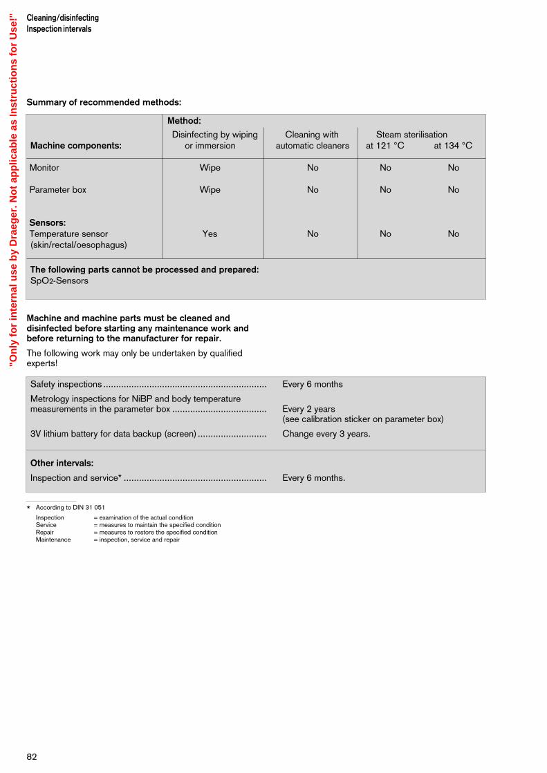
Summary of recommended methods:
Machine and machine parts must be cleaned anddisinfected before starting any maintenance work andbefore returning to the manufacturer for repair.
The following work may only be undertaken by qualifiedexperts!
* According to DIN 31 051
Inspection = examination of the actual conditionService = measures to maintain the specified conditionRepair = measures to restore the specified conditionMaintenance = inspection, service and repair
82
Cleaning/disinfectingInspection intervals
Safety inspections ................................................................ Every 6 months
Metrology inspections for NiBP and body temperaturemeasurements in the parameter box ..................................... Every 2 years
(see calibration sticker on parameter box)
3V lithium battery for data backup (screen) ........................... Change every 3 years.
Other intervals:
Inspection and service* ........................................................ Every 6 months.
Method:
Disinfecting by wiping Cleaning with Steam sterilisation Machine components: or immersion automatic cleaners at 121 °C at 134 °C
Monitor Wipe No No No
Parameter box Wipe No No No
Sensors:Temperature sensor Yes No No No(skin/rectal/oesophagus)
The following parts cannot be processed and prepared:SpO2-Sensors
"On
ly f
or
inte
rnal
use
by
Dra
eger
. No
t ap
plic
able
as
Inst
ruct
ion
s fo
r U
se!"
Contents
Operating elements and displays on the Monitor ......................................84Operating elements and indicators on the Parameter Box ........................ 85Back panel .............................................................................................. 86Dimensions.............................................................................................. 87
83
What's whatContents
What's what
"On
ly f
or
inte
rnal
use
by
Dra
eger
. No
t ap
plic
able
as
Inst
ruct
ion
s fo
r U
se!"

What's what
Operating elements and displays on themonitor
1 Status field with indication of alarm mode
2 Screen for graphs and measured values
3 Date field
4 Field for time and timer
5 User advisory field
6 Field for warning messages
7 Field for caution messages
8 Field for advisory messages
9 Designation of softkeys
10 Softkeys
11 Key for calling up preconfigured screens
12 Key for calling up the standard screen
13 Yellow LED for caution messages
14 Red LED for warning messages
15 Key for suppressing the acoustic alarm
16 Key for freezing displayed real-time curves
17 Key for manual list entry
18 Rotary control
19 Standby key
What's what
84
D
1-2--
Stop
1
3
4
5
13
14
15
17
6 7 8 9 1011 12
16
18
19
2
0892
9094
"On
ly f
or
inte
rnal
use
by
Dra
eger
. No
t ap
plic
able
as
Inst
ruct
ion
s fo
r U
se!"
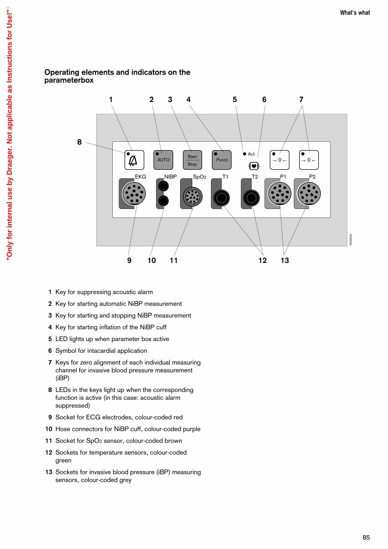
Operating elements and indicators on the parameterbox
1 Key for suppressing acoustic alarm
2 Key for starting automatic NiBP measurement
3 Key for starting and stopping NiBP measurement
4 Key for starting inflation of the NiBP cuff
5 LED lights up when parameter box active
6 Symbol for intacardial application
7 Keys for zero alignment of each individual measuringchannel for invasive blood pressure measurement(iBP)
8 LEDs in the keys light up when the correspondingfunction is active (in this case: acoustic alarmsuppressed)
9 Socket for ECG electrodes, colour-coded red
10 Hose connectors for NiBP cuff, colour-coded purple
11 Socket for SpO2 sensor, colour-coded brown
12 Sockets for temperature sensors, colour-codedgreen
13 Sockets for invasive blood pressure (iBP) measuringsensors, colour-coded grey
85
What's what
g dAUTO
Start
StopPunct.
Act.→ 0 ← → 0 ←
EKG NIBP SpO2 T1 T2 P1 P2
1 2 3 4 5 7
9 10 11 12 13
8
6
0902
9094
"On
ly f
or
inte
rnal
use
by
Dra
eger
. No
t ap
plic
able
as
Inst
ruct
ion
s fo
r U
se!"

Back panel
1 Connection for external RGB screen
2 RS 232 C Connection – serial printer port
3 RS 232 C Connection – serial MEDIBUS port
4 Connection 2 for CAN bus
5 Connection 1 for CAN bus
6 Ventilation slits. Do not block!
7 Ground stud for equipotential bonding
8 Mounting post
9 Fixing thread (M 20 x 2.5 - Allen screw, A/F 12 mm)
10 Adjustment of swivel resistance - Allen screw, A/F 5 mm
11 Adjustment of tilt resistance - Cross-slotted screw
What's what
86
RGB RS 232 C RS 232 C CAN 2 CAN 1
m P
1 2 3 4 5
6
7
8
9
1110
0182
9094
"On
ly f
or
inte
rnal
use
by
Dra
eger
. No
t ap
plic
able
as
Inst
ruct
ion
s fo
r U
se!"

Dimensions
87
What's what
D
1-2--
Stop
H =
265
mm
T = 85 mm
B = 370mm
0912
9094
"On
ly f
or
inte
rnal
use
by
Dra
eger
. No
t ap
plic
able
as
Inst
ruct
ion
s fo
r U
se!"

88
"On
ly f
or
inte
rnal
use
by
Dra
eger
. No
t ap
plic
able
as
Inst
ruct
ion
s fo
r U
se!"
Contents
Power supply .......................................................................................... 90Ambient conditions ..................................................................................90Data communication ................................................................................ 91Electrocardiogram ................................................................................... 91Heart rate ................................................................................................91Non-invasive blood pressure (NiBP) .........................................................92Invasive blood pressure (iBP) .................................................................. 93Oxygen saturation ....................................................................................93Body temperature measurement............................................................... 94Respiration...............................................................................................94Transport function.................................................................................... 95
89
Technical dataContents
Technical data
"On
ly f
or
inte
rnal
use
by
Dra
eger
. No
t ap
plic
able
as
Inst
ruct
ion
s fo
r U
se!"

Technical data
Where tolerances are given in percent and as absolute values, the higher value applies in each case!
Identification The serial number of the PM 8060 vitara and the ç symbol are located on therating plate (nameplate) fixed to the back of the device. The device configuration andequipment level is coded in the appliance number and can therefore be identified.
Weight: About 3.8 kg.
Dimensions 265 x 370 x 85 mm (H x W x D)
Electromagnetic compatibility (EMC)Tested in conformity with EN 60601-1-2
Power supply for the PM 8060 vitara
Operating voltage 19 to 26 VDC
Current consumption Max. 1.5 A (2 A with parameter box)
Power adapter
Operating voltage 85 to 264 VAC, 45 to 65 HZ
Current consumption 0.33 A for 230 V input voltage
Equipment Protection Classes
PM 8060 vitara m , Type B
Power Supply Class 1, m , Type B
Parameter box PB 8800 d , Type CF, protected against defibrillation shocks
Environmental conditions
Temperature 0 to +40 °C (operation)–20 to +60 °C (storage/transport)
Relative humidity 20 to 90%, no condensation (operation)10 to 90%, no condensation (storage/transport)
Technical data
90
"On
ly f
or
inte
rnal
use
by
Dra
eger
. No
t ap
plic
able
as
Inst
ruct
ion
s fo
r U
se!"

Data communication
RS-232-C (MEDIBUS)
Socket 9-pole Sub D, isolation 500V
Pin layout 2 = TxD, 3 = RxD, 5 = Earth
Printer
Socket 9-pole Sub D, isolation 500V
Pin layout 2 = TxD, 3 = RxD, 5 = Earth
Electrocardiogram (ECG)
Input Isolated, IEC type CF; for ECG leads with 3, 4 or 5 electrodes; colour-coded red.
Input impedance > 20 MΩ at 10 Hz> 4 MΩ at 40 Hz
Leads 1, 2, 3 or I, II, III, aVR, aVL, aVF, V
Display Position can be configured as required
Input voltage max. 6 mV peak
Graph display 0.25, 0.5, 1, 2, 4 mV/cm
DC offset max. 300 mV (Filter set to »on«)
Bandwidth 0.5 to 30 Hz (–3 dB; Filter set to »on«)0.05 to 70 Hz (–3 dB; Filter set to »off«)
Interference suppression 50/60 Hz with ECG lead and 5 kΩ unbalanced: > 127 dB
Output impedance < 10 Ω, output current < 1 mA, short-circuit-proof.
Noise < 25 µVpp with an impedance of 51 kΩ // 0.047 µF to each neutral line per electrode
Zero stabilisation Automatic; when the mean peak value exceeds the display range.
Stabilisation time < 0.5 s; artefact message and alarm after 15 seconds.
Pacemaker pulses Automatically magnified on display when detection function active. Not counted in the majority of cases.
Defibrillator Protected against defibrillation shocks; synchronisation pulse available.
Socket receptacle, outer contact: groundSocket receptacle, inner contact: TTL output with 15 ms pulse durationMaximum retardation relative to R-wave: 26 ms
Test specifications EN 601-2-27
Heart rate
Source of heart rate Derived from 1st ECG
Heart beat indication Acoustic and visual; acoustic indication derived from SpO2 value (can be programmed).
Frequency Average value measured over approx. 10 beats
Measuring range 30 to 300 beats per minute
Accuracy ± 2 beats/minute
91
Technical data
1
6
5
9
0922
9094
"On
ly f
or
inte
rnal
use
by
Dra
eger
. No
t ap
plic
able
as
Inst
ruct
ion
s fo
r U
se!"

Pulse deficit indication Difference between heart rate (derived from ECG) and pulse rate (derived from SpO2 ).
Detection of asystolia/ventricular flutter Cannot be deactivated; asystolia alarm after 6 seconds; ventricular flutter
detected after approx. 15 seconds; not available for children.
S-T segment analysis Amplitude ±3 mV,Resolution 0.01 mVMax. heartbeat 150 beats per minuteLead (derivation) Derived from the 1st ECGMeasuring point 40 ms after J point
Non-invasive blood pressure (NiBP)
Input Colour code: lilac. IEC Type CF
Measuring method Oscillometric
Measuring range Adult mode 20 to 290 mmHg (3.0 to 38.6 kPa)Neonatal mode 5 to 150 mmHg (0.6 to 20 kPa).
Accuracy dynamic: 8 mm Hgstatic 4 mm Hg
Measuring unit mmHg or kPa
Cuff inflation For the first measurement, the cuff is inflated to the maximum pressure preselectedby the user (up to 180 mmHg for adults or 100 mmHg for adults); after reading offthe systolic pressure, for the next measurement the cuff must be inflated to 20 mmHgabove the last measured systolic value.
If the inflation pressure is too low for correct measurement of systolic pressure, air is automatically released from the cuff, and the measurement is repeated 5 seconds later with a higher cuff pressure. If this pressure is still too low, air is againreleased from the cuff, and the measurement is repeated 30 seconds later withincreased cuff pressure.
Release air from the cuff – On completion of the measurement.– When measurement is broken off by hand.– When the maximum measuring time is exceeded.– When the maximum cuff pressure is reached.– In the presence of undue artefacts.– In the event of a power failure / when switching off the monitor.– When NiBP function deactivated.
Max. cuff pressure 300 mmHg (40 kPa) for adults150 mmHg (20 kPa) for neonates
Max. measuring time 90 seconds for adults60 seconds for neonates
Intervals for automaticmeasurement every 2nd, 3rd, 5th, 10th, 15th, 20th, 30th and 60th minute.
Manually triggered interim measurement does not affect the time between automatic measurements.
Venous stasis configurable between 10 and 100 mmHG.
Test specifications EN 60 601 - 2 - 30.
Technical data
92
"On
ly f
or
inte
rnal
use
by
Dra
eger
. No
t ap
plic
able
as
Inst
ruct
ion
s fo
r U
se!"

Invasive blood pressure (iBP)
Input Floating, IEC, type CF; colour-coded grey
Input sensitivity 42.5 and 50 µV/V/10 mmHg
Input impedance 90 kΩ (can be changed to 1 MΩ)
Bridge voltage 5 V DC
Bridge impedance 200 Ω to 10 kΩ
Zero alignment Semi-automatic; not possible while pressure continues to fluctuate (with site label »Art« or »Aorta«); range ± 70 mmHg. Inaccuracy < 0.5 mmHg.
Bandwidth 0 to 7 Hz (–3 dB)Measuring rangesfor graph display 5 to 320 mmHg in increments of 5 mmHg
Max. pressure signal –10 to 320 mmHg for undistorted display
Measured parameters Systolic, diastolic and mean pressure
Measuring range –10 to 320 mmHg
Accuracy 0 to 40 mmHg: ± 1 mmHg>40 to 160 mmHg: ± 2 mmHg>160 mmHg: ± 4 mmHg
Measuring unit mmHg
Site labels Art, Aorta, APul, CVP, ICP, ? (the question mark stands for the manually entered sitelabel). A site label automatically controls the adjustment of the measuring range, alarm limits and display configuration for the relevant site.
Test specifications EN 601-2-34
Oxygen saturation (SpO2)
Input Colour code: brown. Floating input, IEC Type CF
Cable type no amplifier
Wavelengths 660 nm (red) and 920 nm (infrared)
Display refresh rate After every pulse
Alarm limit Adjustable from 50 % to 100 %
Measuring range 0 to 105 %
Accuracy Adults:0 to 50 % undefined50 to 70 % ± 3 %70 to 100 % ± 2 %
Neonates:0 to 70 % undefined70 to 100 % ± 3 %
Accuracy of Durasensor ± 3% (additional)
Measuring modes Normal mode: measurement over 5 to 7 secondsFast mode: 2 to 3 secondsSlow mode: 10 to 15 secondsOff: Module deactivated
93
Technical data"O
nly
fo
r in
tern
al u
se b
y D
raeg
er. N
ot
app
licab
le a
s In
stru
ctio
ns
for
Use
!"
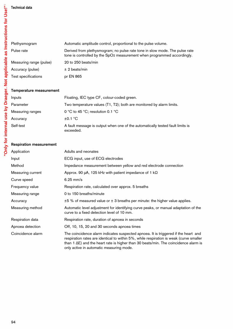
Plethysmogram Automatic amplitude control, proportional to the pulse volume.
Pulse rate Derived from plethysmogram; no pulse rate tone in slow mode. The pulse rate tone is controlled by the SpO2 measurement when programmed accordingly.
Measuring range (pulse) 20 to 250 beats/min
Accuracy (pulse) ± 2 beats/min
Test specifications pr EN 865
Temperature measurement
Inputs Floating, IEC type CF, colour-coded green.
Parameter Two temperature values (T1, T2); both are monitored by alarm limits.
Measuring ranges 0 °C to 45 °C; resolution 0.1 °C
Accuracy ±0.1 °C
Self-test A fault message is output when one of the automatically tested fault limits isexceeded.
Respiration measurement
Application Adults and neonates
Input ECG input, use of ECG electrodes
Method Impedance measurement between yellow and red electrode connection
Measuring current Approx. 90 µA, 125 kHz with patient impedance of 1 kΩ
Curve speed 6.25 mm/s
Frequency value Respiration rate, calculated over approx. 5 breaths
Measuring range 0 to 150 breaths/minute
Accuracy ±5 % of measured value or ± 3 breaths per minute: the higher value applies.
Measuring method Automatic level adjustment for identifying curve peaks, or manual adaptation of thecurve to a fixed detection level of 10 mm.
Respiration data Respiration rate, duration of apnoea in seconds
Apnoea detection Off, 10, 15, 20 and 30 seconds apnoea times
Coincidence alarm The coincidence alarm indicates suspected apnoea. It is triggered if the heart andrespiration rates are identical to within 5%, while respiration is weak (curve smallerthan 1 ∆E) and the heart rate is higher than 30 beats/min. The coincidence alarm isonly active in automatic measuring mode.
Technical data
94
"On
ly f
or
inte
rnal
use
by
Dra
eger
. No
t ap
plic
able
as
Inst
ruct
ion
s fo
r U
se!"
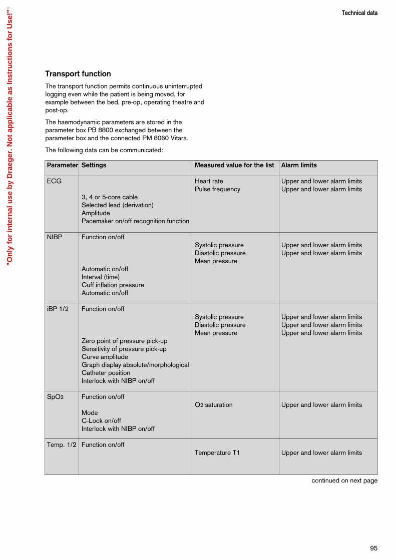
Transport function
The transport function permits continuous uninterruptedlogging even while the patient is being moved, forexample between the bed, pre-op, operating theatre andpost-op.
The haemodynamic parameters are stored in theparameter box PB 8800 exchanged between theparameter box and the connected PM 8060 Vitara.
The following data can be communicated:
95
Technical data
continued on next page
Parameter Settings Measured value for the list Alarm limits
ECG Heart rate Upper and lower alarm limitsPulse frequency Upper and lower alarm limits
3, 4 or 5-core cableSelected lead (derivation)AmplitudePacemaker on/off recognition function
NIBP Function on/offSystolic pressure Upper and lower alarm limitsDiastolic pressure Upper and lower alarm limitsMean pressure
Automatic on/offInterval (time)Cuff inflation pressureAutomatic on/off
iBP 1/2 Function on/offSystolic pressure Upper and lower alarm limitsDiastolic pressure Upper and lower alarm limitsMean pressure Upper and lower alarm limits
Zero point of pressure pick-upSensitivity of pressure pick-upCurve amplitudeGraph display absolute/morphologicalCatheter positionInterlock with NIBP on/off
SpO2 Function on/offO2 saturation Upper and lower alarm limits
ModeC-Lock on/offInterlock with NIBP on/off
Temp. 1/2 Function on/offTemperature T1 Upper and lower alarm limits
"On
ly f
or
inte
rnal
use
by
Dra
eger
. No
t ap
plic
able
as
Inst
ruct
ion
s fo
r U
se!"

96
Parameter Settings Measured value Alarm limitsfor the list
Resp. Function on/offTrigger mode (manual/automatic) Upper and lower alarm limitAmplitude
General Storage times of dayStorage marks
Application modeSite nameStart time of monitoring phaseEnd time of monitoring phasePatient name
Data transferred from the anaesthetic or ventilation machine
Parameter Measured value for the list Alarm limit
None NoneEnd-expiratory CO2
Inspiratory O2
Ventilation minute volume AMV Inspiratory anaesthetic gas concentrationAirway peak pressure PeakAirway pressure level PEEPCompliance
"On
ly f
or
inte
rnal
use
by
Dra
eger
. No
t ap
plic
able
as
Inst
ruct
ion
s fo
r U
se!"

Contents
Abbreviations and symbols....................................................................... 98
Index......................................................................................................101
97
DescriptionContents
Description
"On
ly f
or
inte
rnal
use
by
Dra
eger
. No
t ap
plic
able
as
Inst
ruct
ion
s fo
r U
se!"
Abbreviation and symbols
Abbreviation Meaning
A/F Width across flats
Act. "Activity" (LED in the parameter box)
AMV Minute ventilation
BW Body weight
CAL Calibration has been performed
C-Lock Cardio-Lock (ECG synchronised)
Cpat Patient compliance
DGHM German Society for Hygiene and Microbiology
et CO2 End-expiratory CO2 concentration
Fet Des. End-expiratory desflurane concentration
Fet Enf. End-expiratory enflurane concentration
Fet Hal. End-expiratory halothane concentration
Fet Iso. End-expiratory isoflurane concentration
Fet N2O End-expiratory N2O concentration
Fet Sev. End-expiratory sevoflurane concentration
Fi Des. Inspiratory desflurane concentration
Fi Enf. Inspiratory enflurane concentration
Fi Hal. Inspiratory halothane concentration
Fi Iso. Inspiratory isoflurane concentration
Fi Sev. Inspiratory sevoflurane concentration
Fi N2O Inspiratory N2O concentration
Fi O2 Inspiratory O2 concentration
Hb Haemoglobin
HbCO Carbon monoxide haemoglobin
HbO2 Oxyhaemoglobin
in CO2 Inspiratory CO2 concentration
INOP Malfunction
IPPV Automatic ventilation mode: intermittent positive pressure ventilation
LED Light-emitting diode
Man./Spont. Manual ventilation or spontaneous breathing
Mean Mean pressure
NTC Resistance-type temperature sensor with negative temperaturecoefficient
DescriptionAbbreviations and symbols
98
"On
ly f
or
inte
rnal
use
by
Dra
eger
. No
t ap
plic
able
as
Inst
ruct
ion
s fo
r U
se!"
Abbreviation Meaning
Off Switched off, deactivated
ON Switched on, activated
Paw Airway pressure
PC Personal computer (IBM compatible)
Peak Actual measured peak pressure
Plat Plateau pressure
Pleth. Plethysmogram
Pmean Mean airway pressure
Power Electricity supply
PEEP Positive end-expiratory pressure
Resp. Respiration
SIMV Synchronised intermittent mandatory ventilation
SpO2 Functional O2 saturation
99
DescriptionAbbreviations and symbols
"On
ly f
or
inte
rnal
use
by
Dra
eger
. No
t ap
plic
able
as
Inst
ruct
ion
s fo
r U
se!"

DescriptionAbbreviations and symbols
100
Symbol Meaning
ª Pulse rate
< Lower alarm limit
> Upper alarm limit
_ Alarm monitoring inactive
Close menu, return to previous menu level
1 Changeover switch for Standby and Measuring modes
$ Cyclic activation of basic pages
% Display standard page
3 Suppress acoustic alarm for 2 minutes
P Connection for equipotential bonding
m Protection class type B (DIN IEC 601)
m Protection class type BF (DIN IEC 601)
d Protection class CF, protected against defibrillation shock
? Request for calibration
Action has been completed successfully
u Action in progress
!!! Warning message
!! Caution message
! Advisory message
– – Alarm limit deactivatedu
"On
ly f
or
inte
rnal
use
by
Dra
eger
. No
t ap
plic
able
as
Inst
ruct
ion
s fo
r U
se!"
Abbreviations ........................................................... 98Accessories ................................................................ 4Accessories, care ..................................................... 81Acoustic, Standby .................................................... 31Active agents, cleaning and disinfecting .................... 80Alarm concept .......................................................... 45Alarm info, operation ................................................ 42Alarm limits, auto set ................................................ 41Alarm limits, blood pressure, monitoring ................... 48Alarm limits, pulse rate, monitoring ........................... 47Alarm limits, standby ................................................. 23Alarm priority ............................................................ 45Alarm tone, deactivating .............................................. 6Alarms, linkage ......................................................... 47Alarms, show all ....................................................... 46Apnoea alarm, respiration ......................................... 71Arrow, return ............................................................ 22
Basic configuration, standby .................................... 35Blue holder, parameter box ....................................... 51
Care ........................................................................ 79Care of accessories ................................................. 81Care of device .......................................................... 80Cause, fault messages and remedy (troubleshooting) ...................................................... 73Coincidence alarm, respiration ................................. 71Configuring general settings, standby ....................... 31Connecting, "Cato" .................................................. 15Connecting, external devices .................................... 14Connecting, "Julian" ................................................. 15Connecting, system .................................................. 14Connection with other electrical equipment ................. 4Controls, screen, user interface .................................. 8Curve speed, configuring, standby ........................... 31
Data communication, technical data ......................... 91Data transfer, fully automatic, parameter box ............. 52Data transfer, parameter box .................................... 52Data transfer, semi-automatic, parameter box ........... 52Data, technical ......................................................... 89Default values, changing ........................................... 21Device, care ............................................................. 80Device, cleaning/disinfecting .................................... 80Device, stripping ...................................................... 80Device, switching on ................................................ 14
Dimensions .............................................................. 87Disposable articles, disposing of ............................... 80
ECG settings, standby ............................................. 24ECG, adjusting settings ............................................ 55ECG, applying electrodes ........................................ 54ECG, display ............................................................ 54ECG, ST segment analysis ....................................... 56ECG, technical data ................................................. 91ECG/heart rate, parameter box ................................. 53Environmental conditions, technical data ................... 90
Field, black/white ..................................................... 22Field, orange ............................................................ 22Formaldehyde .......................................................... 80Full trend, operation ................................................. 39Function keys, parameter box ................................... 50
Graph modules ........................................................ 28
Hardkeys ................................................................... 8Heart rate, technical data .......................................... 91Holder for OP table, parameter box .......................... 51Holder, blue, parameter box ..................................... 17Holder, OP table, parameter box .............................. 17Holder, slot-in housing, parameter box ...................... 17
iBP channels, standby .............................................. 25iBP locations, standby .............................................. 25iBP, calibrating sensors ............................................ 61iBP, changing settings .............................................. 62iBP, display .............................................................. 63iBP, setting functions ................................................ 62iBP, starting monitoring ............................................ 61iBP, technical data .................................................... 93Indicator lamps ......................................................... 10Indicators, parameter box ......................................... 50Instructions for use, strictly follow ............................... 4Instructions for use, working with, general .................. 2Intended use, medical ................................................. 6Interface, MEDIBUS, standby ................................... 34Interface, printer, standby ......................................... 34
Keys with dedicated function (hardkeys) ..................... 8Keys with variable function (softkeys) .......................... 8
Index
101
Index
"On
ly f
or
inte
rnal
use
by
Dra
eger
. No
t ap
plic
able
as
Inst
ruct
ion
s fo
r U
se!"

102
Index
Liability ....................................................................... 4Limits setting, operation ............................................ 40Linkage, alarms ........................................................ 47List entry, standby .................................................... 32List intervals, parameter box ..................................... 52List screen, operation ............................................... 37
Maintenance .............................................................. 4Menu structure ......................................................... 10Messages on the monitor ......................................... 75Messages, where they occur .................................... 74Methods, cleaning and disinfecting ........................... 80Mode, adults/neonates ............................................. 22
NiBP settings, standby ............................................. 24NiBP, adjusting settings ............................................ 59NiBP, applying the sphygmomanometer cuff ............. 56NiBP, interrupting measurement ............................... 58NiBP, limitations of measuring method ...................... 57NiBP, measuring blood pressure of neonates ........... 60NiBP, starting monitoring .......................................... 58NiBP, technical data ................................................. 92Numerical modules ................................................... 29
Operating concept ..................................................... 7
Pacemaker pulse detection, parameter box .............. 53Parameter box .......................................................... 49Parameter box, fitting ................................................ 17Parameter, operation ................................................ 42Parameters, standby ................................................. 23Patient alarms, auto setting ....................................... 41Patient safety .............................................................. 4Power supply, connecting ........................................ 14Power supply, technical data .................................... 90Precautions for use ..................................................... 6Preparation for use ................................................... 13Protection classes, technical data ............................. 90
Remedy, fault messages and cause .......................... 73Respiration measurement, automatic ........................ 71Respiration measurement, manual ............................ 71Respiration measurement, technical data .................. 94Respiration monitoring in operating theatre ............... 72Respiration, applying electrodes ............................... 71Respiration, cardiorespirogram ................................. 70
Respiration, messages ............................................. 72Respiration, standby ................................................. 26Respiration, starting monitoring ................................. 70Return arrow ............................................................ 22Rotary control ............................................................. 9
Safety, for your own and that of your patients ............. 4Screen background, configuring ............................... 30Screen colours, configuring ...................................... 30Screen configuration, operation ................................ 42Screen functions ...................................................... 19Screen module, graph .............................................. 28Screen module, numerical ........................................ 29Screen saver ............................................................ 11Screen structure ....................................................... 10Screen, configuring, operation .................................. 43Screen, configuring, standby .................................... 20Screen, configuring, standby, calling up ................... 20Screen, configuring, temporary ................................. 20Screen, starting up ................................................... 35Show, all alarms ....................................................... 46Slot-in housing, parameter box .................................. 17Softkeys ..................................................................... 8SpO2, changing settings .......................................... 64SpO2, choice of sensor ............................................ 66SpO2, coupling with NiBP ........................................ 67SpO2, display ........................................................... 64SpO2, measuring principle ....................................... 67SpO2, safety and precautions ................................... 65SpO2, setting functions ............................................ 65SpO2, technical data ................................................ 93SpO2, tips to avoid artefacts ..................................... 67SpO2/plethysmogram, standby ................................. 25Standard screen, operation ...................................... 37Standard screens, configuring, standby .................... 27Standard screens, configuring, standby .................... 27Suppressing, alarm tone ........................................... 46Swivel arm, mounting ............................................... 16Symbols ................................................................... 98
Technical data .......................................................... 89Temperature measurement, display .......................... 69Temperature measurement, measuring principle ....... 69Temperature measurement, starting measurement .... 69Temperature measurement, technical data ................ 94Tilting, screen ........................................................... 16
"On
ly f
or
inte
rnal
use
by
Dra
eger
. No
t ap
plic
able
as
Inst
ruct
ion
s fo
r U
se!"

Timer, operation ....................................................... 43Transport function, parameter box ............................ 51Transport function, standby ...................................... 32Transport function, technical data ............................. 95Trend screen, operation ............................................ 39Troubleshooting ........................................................ 73Turning and tilting, screen ......................................... 16
What's what ............................................................. 83What's what, back panel of monitor .......................... 86What's what, dimensions .......................................... 87What's what, monitor ............................................... 84What's what, parameter box ..................................... 85White housing, parameter box .................................. 51Wipe-cleaning .......................................................... 80
Zoom function, trend screen, operation .................... 39
Index
103
"On
ly f
or
inte
rnal
use
by
Dra
eger
. No
t ap
plic
able
as
Inst
ruct
ion
s fo
r U
se!"

These Instructions for Use apply only toPM 8060 vitarawith Serial No.:
If no Serial No. has been filled in by Drägerthese Instructions for Use are provided forgeneral information only and are notintended for use with any specificmachine or device.
Dräger Medical AG & Co. KGaAGermanyz Moislinger Allee 53 – 55
D-23542 Lübecky +49 451 8 82 - 0x 26 80 70FAX +49 451 8 82-20 80! http://www.draeger.com
90 29 095 - GA 6497.705 en Dräger Medical AG & Co. KGaA3rd edition - July 2001Subject to alteration
çDirective 93/42/EECconcerning Medical Devices
"On
ly f
or
inte
rnal
use
by
Dra
eger
. No
t ap
plic
able
as
Inst
ruct
ion
s fo
r U
se!"