plasma simulation by artificial dielectrics and parallel-plate media-xy9
DESCRIPTION
Plasma Simulation by Artificial Dielectrics and Parallel-plate Media-xy9TRANSCRIPT

82 IRE TRANSACTIOXS O N AATTENNAS AArD PROPAGATION Janua y
ing thickness of the plasma layer, while for a fixed thick- ness the number of oscillations decreases as up is in- creased. For C<O P(4) equals 1 at 4 = 0 and decreases
, I monotonically as increases to ~ / 2 . This decrease in power is sharp because of the hyperbolic cosine term in i
I
the denominator and is more marked for larger CI or I , L (Fig. 2) .
ACKNOWLEDGMENT 0.2 The authors wish to express their gratitude to Dr. A.
Hessel of the Polytechnic Institute of Brooklyn, Micro- wave Institute, who suggested the approach used in this paper.
0 I..-
30 I80 0
Fig. 2-Radiation pattern of plasma-covered magnetic line source.
Plasma Simulation by Artificial Dielectrics and Parallel-Plate Media* WALTER ROTMANT, EMBER, IRE
Summary-A plasma in the absence of dc magnetic fields is representable, from the electromagnetic viewpoint, as a lossy di- electric with a complex index of refraction whose real part is less than one. I ts electrical properties, such as propagation constant and intrinsic impedance, can be simulated by microwave structures, such as artiiicial dielectrics of lossy metallic rods, and by H-plane parallel- plate guides.
Design techniques are presented for application to the modeling of plasma media. Examples include problems of radiation from antennas on a plasma-coated ground plane, with magnetic line sources and electric aperture radiators simulated by parallel-plate guides and rodded media, respectively. Radiation patterns of these models show good agreement with established theory. Waveguide measurements on the rodded media also confirm the expected propagation and impedance characteristics.
I. INTRODUCTION
homogeneous, analytic solutions are not always possible. Experimental techniques for simulating the effects of plasma upon radiative systems are therefore desirable.
For purposes of simulation, the plasma in the absence of dc magnetic fields can be represented as an isotropic lossy dielectric whose magnetic permeability is unity, its complex dielectric constant eP and propagation con- stant y p respectively given by'
and
ROBLEMS of aerospace research dealing with the where up is the plasma frequency, v is the collision fre- interaction of microwave radiation with shock- quency, and po are the dielectric constant and mag- ionized flow fields and other plasmas involve the netic permeability of freespace, respectively.
effects of plasma sheaths and rocket exhausts upon the This representation neglects nonlinear (strong sig- radiation and impedance of re-entry-vehicle antennas nal) interactions with the electromagnetic radiation and and radar reflections from ionized trails. Since the vehic- self-radiation. Under these restrictions the plasma has ular geometry is usually complex and the plasma is not a complex index of refraction whose real part is less than
Received by the PG.lP, October 2, 1961. 1 R. F. IVhitmer, "Principles of microwave interactions with ion- t Electromagnetic Radiation Lab., 4F Cambridge Research ized media; Part I: Plasma resonance," Xicrozcrave J., pp.
Labs., Bedford, Mass. 17-19; February, 1959.
Authorized licensed use limited to: IEEE Xplore. Downloaded on May 10,2010 at 19:00:04 UTC from IEEE Xplore. Restrictions apply.

1962 Rotman: Plasma Simulation by Airfl:ficid Dielectrics a.nd Parallel-Plate Jiedicr
unity. Obviouslp, since all materials have refractive indexes greater than unity, the plasma cannot be simu- lated by any- real dielectric. Several techniques for plasma simulation, including the use of lumped electric circuit elements and mechanical analogs, have been suggested.2 In our approach, the behavior of the plasma is approximated by using artificial media that have electrical characteristics similar to those of the plasma. The two types of artificial media investigated were: 1) an artificial dielectric composed of periodically spaced lattices of metallic rods, 2) a parallel-plate guide carrying the fundamental TEol mode.
In general, the electrical properties of any isotropic homogeneous dielectric including plasma can be char- acterized by two complex quantities a t a single fre- quency; the complex dielectric constant and magnetic permeability or, alternatively, the propagation con- stant and characteristic impedance. Hence, four scalar parameters (the real and imaginary parts of two inde- pendent complex quantities) must be simulated to ap- proxiate the electrical properties of the plasma.
For a plasma (in the absence of an external magnetic field) the propagation constant is related to the charac- teristic impedance by3
where 2, is the characteristic impedance of plasma, 2 0
the characteristic impedance of free space, and x /pOj l~ , , is the free space propagation constant.
medium that simulates the electrical characteristics of the plasma must satisfy the proportionality of (3) and must therefore have a relative magnetic permeability of unity.
Previous simulation techniques approximate one or two of the characteristic scalar parameters of the plasma but neglect the others. For example, conductivesolu- tions of acids or salts can give the proper attenuation constant, but their refractive index is greater than unity. Also, artificial media made of metal spheres, holes in plates, or disks can have a propagation constant equivalent to that of a plasma but the relative magnetic permeability- of such media differs significantly from unity.
Rodded artificial dielectrics and parallel-plate struc- tures tend to maintain the characteristics of plasma media, such as the relation between the characteristic impedance (which determines the reflection a t inter- faces) and the propagation constant. Their applica- tion to antenna-plasma interaction problems will be dis- cussed after a consideration of their characteristics and design parameters.
to the ionosphere, H-ire lm Efzp., vol. 31, pp. 321r326; December, R. N. Bracew~ll, ‘Analogues of an ionized medium: applications
1951. R. I‘on Hippel, “Dielectrics and \l:aves,” Technology Press,
Cambridge, Mass., pt. 1, sect. pp. 20-21; 1954.
The rodded medium consisting of a tn-o- or three- dimensional rectangular lattice of Ivire grids (Fig. 1) has been extensively i n ~ e s t i g a t e d ~ - ~ in microwave lens design for its desirable low-loss characteristics. In plasma simulation, to cover a wide range of parameters, rodded media are desirable for their medium- and high- loss characteristics. These can be obtained by using either grids of resistive wires or lossy embedding di- electric. Onl); the resistive wire medium is treated here, since lossy dielectrics usually have refractive indexes whose real parts are substantially greater than unity.
u
(c)
Fig. 1-The rodded media. (a ) Two-dimensional lattice, electric field in direction. (b) Three-dimensional lattice, electric field in
plane. ( c ) Three-dimensional lattice, arbitrary polarization.
than unity,” PTOC. IEE, hlonograph KO. 62R, vol. 100, pt. pp. J. Brown. “Artificial dielectrics having refractiL-e indices less
51-62; May, 1953. J. Brown and Jackson, “The properties of artificial dielec-
trics a t centimetre waveleneths.“ Proc. IEE. uauer no. 1699R. vol. 102B, pp. 11-21; January, 1955.
type artificial dielectric,” Proc. IEE, paper no. 2742R, col. 105C, A. Carne and J. Brown, “Theory of reflections from the rodded-
pp. 105-115; November, 1958.
rials,” Proc. IEE, paper no. 2i36R, vol. IOK, pp. 103-106; No- J. s. Seeley, “The quarter-wave matching of dispersive mate-
vember, 1958.
electrics in a beam scanning prism,” Proc. IEE, paper no. 2735R, J. S. Seeley and J. Brown, “The use of dispersive artificial di-
vol. 105C, pp. 93-102; Kovember, 1958. 9 A. M. Model, “Propagation of plane electromagnetic waves in a
space which is filled with plane parallel grids,” Radiotekknika, vol. 10, pp. June, 1955. (In Russian.)
Authorized licensed use limited to: IEEE Xplore. Downloaded on May 10,2010 at 19:00:04 UTC from IEEE Xplore. Restrictions apply.

84 IRE TRA:VSACTIONS ON ANTEXNAS AXD PROPAGATION Januarry
The equation for the complex propagation constant in a rodded medium with resistive wires is derived in the Appendix as
ZO
sin (T) where
yr =ar+j& the complex propagation constant in the rodded artificial dielectric
b =the grid spacing in the direction of wave propagation [Fig. 1 (a)
E,,,= the relative dielectric constant of the lossless embedding medium
X. the free space wavelength the free space characteristic impedance
the grid impedance. and
The shunt impedance of a grid of lossy rods is com- posed of two the internal impedance of the rods, and the reactive impedance of a grid of equiva- lent lossless rods.12-14 Thus,
where
is the shunt reactance of a lossless grid of rod diameter and rod spacing a [Fig. l ( a ) ] for a normally incident
plane wave and an electric field parallel to the rods; Ri and Xi are, respectively, the resistive and reactive com- ponents of the impedance of a single rod.15
For low and medium attenuation (a,/&<<l), (4) sepa- rates into the approximate relations
parallel palr of wire gratings," J . O p f . Am., vol. 42, pp. 971-977; J . P..Case>-, Jr., and E. A . Lewis, "Interferometer action of a
December, 1952. l1 E. A. Lewis and J. P. Casey, "Reflection and transmission by
resistive gratings,'' J . AppZ. Phys., vol. 23, p. June, 1952. l2 J. K. Skwirzynski and J. C. Thackray, Transmission of elec-
vol. 22, 2nd qtr., pp. 77-90; 1959. tromagnetic waves through wire gratings (theory)," X a r c o ~ i Rev.,
l 3 E. G. Z. Goodall and A. C. Tackson. "Transmission of elec- tromagnetic waves throuph-wire crritinps le&erimentall." Xarcon i Rk., vol. 22, 2nd qtr.;pp.%1-98; 1359.
T. Decker, Transmission and reflection by a parallel wire grid," J. vol. 63D, pp. 87-90; July-August, 1959.
S. Ram0 and J. R. lyhinnery, "Fields and IiTaces in Modern Radio," John \Viley and Sons, Inc., Y e a York, N. Y. , sects. 6-08
where
X 0
2 r $2
is the effective index of refraction of the rodded me- dium,l6 and
is the normalized grid impedance. Since (6) is qualitatively of the same form as the ex-
pression for a lossless rodded medium3 (with a minor modification of the grid reactance), the phase velocity -frequency behavior of a rodded medium with small or moderate attenuation is similar to that of the lossless structure. The expressions for index of refraction cut- off wavelength X,, degree of isotropy, and similar pa- r a m e t e r ~ ~ - ~ for the lossless case can, therefore, serve as guides in obtaining the approximate dimensions and electrical characteristics of the lossy rodded medium.
An inspection of (6) shows that the phase velocity- frequency behavior of the lossy rodded medium (for the case ern 1) follows that of a slightly lossy plasma. In fact, under the conditions
(1) and (2) for the propagation constant of a plasma reduce to the simplified form1
( 3 1 ' 2
c
and
(VP)']"" f f p
The phase constant 0, for moderately lossy plasma does not depend on the collision frequency and is there- fore independent of the attenuation for a constant plasma frequency. Eq. the relation for the phase constant, is identical in form with that for a lossless waveguide or a lossless plasma. 4 t high frequencies, the effective indices of refraction for both the lossy rodded medium and plasma are close to unity, and the atten- uation constants are small. Below some critical fre- quency (the plasma frequency w p for plasma or the cut- off frequency w c for the rodded medium), the phase constant becomes small and the attenuation increases
duces to (4) of Seelev' under the approximation that Zl<<Zp Eq. (7) for the attenuation constant of a rodded medium re-
to 6-10, pp. 242-248; 1953.
Authorized licensed use limited to: IEEE Xplore. Downloaded on May 10,2010 at 19:00:04 UTC from IEEE Xplore. Restrictions apply.

n~arkedly. .Although (6) and are approximate, exact values of attenuation and phase constants may be ob- tained from (4) for the geometry of a given rodded medium.
The characteristic impedance Z, of the rodded me- dium is related to its other electrical characteristics and geometry bl: (see -Appendix for derivation)
where 7,. is defined by (4). If the propagation constant i n the rodded medium is made equal to that of the plasma (rl =yp), (3) and 1) may be combined to give
where
X 0
The ratio of the characteristic impedance of the rodded medium to that of the plasma Z,/Z, approaches unity (the condition required for accurate plasma sim- ulation) only in the limit as the grid spacing b becomes very small; however, for equal grid and rod spacing (a b ) and a given index of refraction, the diameter of the rods becomes impractically small a t microwave frequencies as the grid spacing ratio bdc/hO decreases below about This lower limit on permissible grid spacing can lead to substantial errors (on the order of 15 per cent for n 0.5) in the characteristic impedance ratio. Several techniques, among them the use of resist- ive films a t interfaces between the rodded medium and free space, are being investigated in an effort to reduce these errors.
For an arbitrary angle oi incidence, the reflection and transmission of a wave striking an air-plasma interface are determined by Fresnel's equations. The angular de- pendence of the characteristic impedance cos (for the case where the electric field is parallel to the plane of incidence) in the Fresnel equations is also required for the grid impedance in the rodded medium for plasma simulation. The reactance of a lossless grid of rods is given by"*'?
s, log, (2;d)COSm+ (13) X0
where F(+, a/ho) is a complex function of the angle of incidence and rod spacing. If the rod spacing is equal to
or less than however, the factor F(+, a.'Xc,j is less than 0.1 for all values of and may be neglected. The grid impedance then has the required cos variation with angle so that Fresnel's equations for the rodded medium become similar to those for the plasma dielec- tric. The restriction of grid and rod spacing to less than
therefore satisfies the requirements for both char- acteristic impedance and isotropic behavior in plasma simulation modeling.
111. PARALLELPLATE M E D I A
Parallel-plate guides carrying the TEo1 mode appear to better advantage than the rodded media because of their wider range of complex propagation constants and easier construction for plasma simulation; but their use is limited to two-dimensional problems, since they per- mit only linear polarization and planar propagation. Their electrical characteristics important to plasma sim- ulation include a complex propagation constant and re- flections a t air-parallel-plate interfaces.
A resistive sheet is placed between the plates (Fig. 2) to provide attenuation since perfectly conducting paral- lel plates are lossless for the TEol mode. The electrical characteristics of this lossy type of guide are discussed by Knudsen,'? who derives analytic expressions for the complex propagation constant as a function of the plate spacing lz and of the position 6 and resistivity X of the resistive sheet. The geometry required for a given com- plex propagation can be determined from tables (based on Knudsen's equations) now in preparation.ls The simulation of nonhomogeneous plasma is achieved bq; varying the plate spacing and position of the resistive sheet in accordance with the desired plasma character- istics.
(b ) Fig. 2-Lossy parallel-plate guide (TEol mode). (a) Parallel plates
with resistive sheet. (b) Ii'aveguide equivalent.
brane conductrice," L'onde elect., vol. 33, no. 313, pp. 217-234; April, L. Knudsen, "Champ dans un guide rectangulaire A mem-
1953.
Rectangular b'aveguide with a IZesistive Sheet,'' AF Cambridge '8 C. E. Ellis and LY. Kotman. "Dominant Mode Propagation i n
Research Labs., Bedford, Mass., Tech. Rept. ( I n preparatioll.
Authorized licensed use limited to: IEEE Xplore. Downloaded on May 10,2010 at 19:00:04 UTC from IEEE Xplore. Restrictions apply.

For two-dimensional structures such as a planar plasma-air boundary or parallel-plate guide (TEoI mode), the reflection coefficient for a wave incident a t an arbitrary angle of incidence can be obtained for- m a I I ~ 7 ~ ~ from the reflection a t normal incidence by sub- stituting for y in the equations, where y is the complex propagation constant in the direction normal to the wavefront and is its component along the longitudinal axis. For normal incidence the reflection co- efficient r at a plasma-air interface is
where Zo and 2, are the respective intrinsic impedances, and and y p are the respective complex propagation constants of free space and the plasma medium. The re- flection coefficient a t oblique incidence is obtained by substituting for y p and ~ / Y O ~ - - Y ~ ~ for yo, so that
where z T / z m and YT/ Y m are, respectively, the terminal impedance and admittance of the structure, normalized relative to the characteristic impedance of the parallel- plate guide. Since the same transformation of propaga- tion constant with angle of incidence applies to both the plasma and the parallel-plate media, the variation of their reflection coefficients with both frequency and angle of incidence can be made identical, provided
Z T Y p
Z m Z p YO (18)
and
Y m Y p , (19)
where ym is the complex propagation constant of the parallel-plate medium.
Eqs. (18) and (19) are the conditions for plasma sim- ulation with respect to propagation constant and reflec- tion coefficient as well as the transmission coefficient which is uniquely determined by these equations, Snell’s law, and one of the Fresnel equations. For the special case of a lossless plasma, (1)-(3) reduce to
where
where up is the plasma collision frequency and is the wavelength in the plasma medium. The propagation constant for the TE,, mode in a lossless parallel-plate guide is given by
Y z sin YO
and
sin Y z
YP
where and J. are the complex angles of incidence and refraction, respectively.
Eq. (15) can also be obtained by combining Fresnel’s equation with Snell’s law of refraction
sin4 Z p YO
sin$ ZO y P (16)
For a two-dimensional parallel-plate guide, the reflec- tion at normal incidence can be expressed in the form
Z T Y,
Part I : Rectangular kVaveguides,” Polytechnic Inst. of Brooklyn, l 9 L. Gddstone and A. A. Oliner, “Leaky LYave Antennas;
Y., Rept. KO. R-606-57, PIB-534, Contract AF19(604)-2031; Au- gust, 1957. See also, IRE TRANS. ANTENSAS AND PROPAG-~TIOK, vol. .4P-7. pp. 307-319; October, 1939.
where
W .YO ha
~e kc 2h I .
lz being the separation of the plates. The identities of (18) and (19) for plasma simulation then become, for the lossless case,
y m x 0 x0
Y T hp xm
and
w, up. (23)
Eq. (23) ensures that the propagation constants and the refractive index, as expressed by Snell‘s equations, are identical for the plasma and the parallel-plate media, and (22) ensures equality for their complex reflection and transmission coefficients.
The normalized terminal admittance YT/ Y, of a pair of parallel plates radiating into a half-space is, in gen- eral, a complicated function20 of the plate spacing h
Marcuvitz, “Waveguide Handbook,” M.I.T. Rad. Lab. Ser., McGraw-Hill Book Co., Inc., New York, Y., vol. 10, sect. 4.9, pp. 1951.
Authorized licensed use limited to: IEEE Xplore. Downloaded on May 10,2010 at 19:00:04 UTC from IEEE Xplore. Restrictions apply.
and operating frequenq-. Under the restriction that h . X7>L<<l, this adnlittance has the approximate value
where
and
Since the restriction hih,,<<l also implies that
(25)
which is of the form of except that the constant coefficient is 0.570-j0.312 instead of unity. This coeffi- cient can be changed to the desired value of unity by adding an admittance of (0.430Sj0.312) to this boundary.
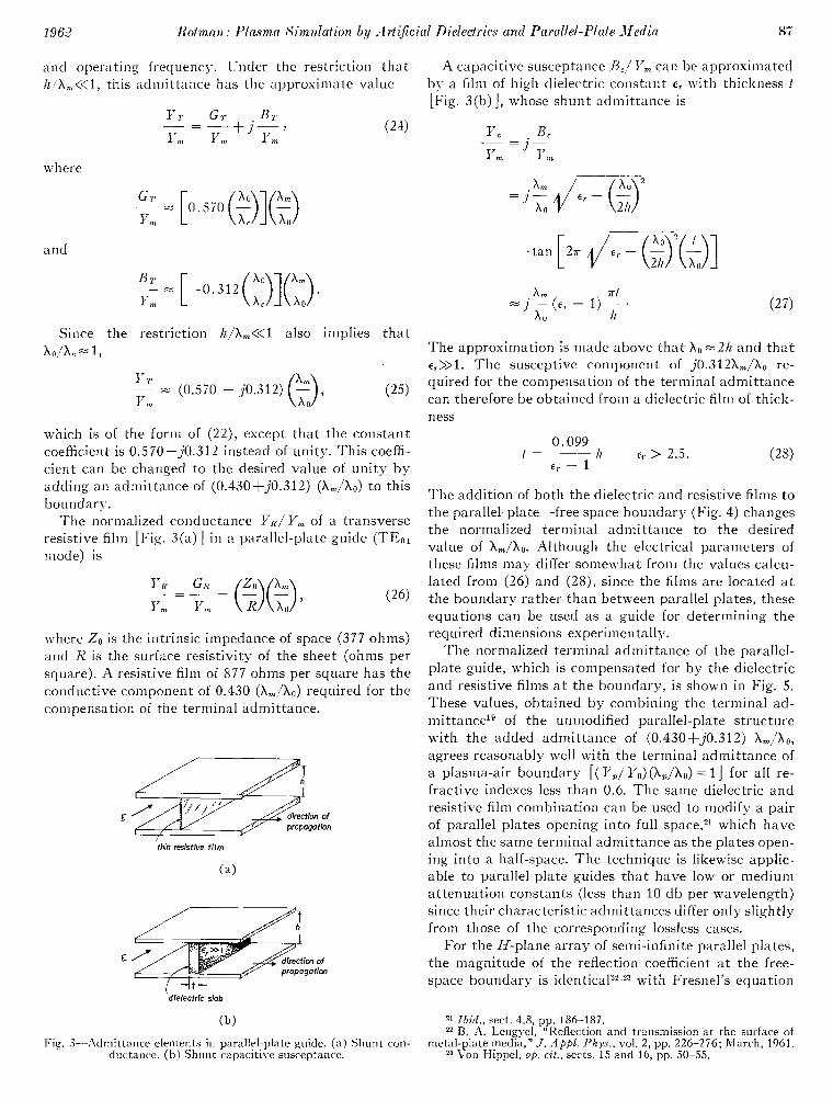
The normalized conductance E’R:I;E.:, of a transverse resistive film [Fig. 3(aj] i n a parallel-plate guide (.TEol mode) is
(26) I‘,
where is the intrinsic impedance of space (3i7 ohms) and K is the surface resistivity of the sheet (ohms per square). A resistive f i l m of 877 ohms per square has the conductive component of 0.430 required for the compensation of the terminal admittance.
thin &stlve
E gatlon
dlelecirlc
(b)
Fig. ?-.Admittance elements i n paral!el-plate guide. Shunt con- ductance. ( b ) Shunt capacitive susceptance.
-A capacitive susceptance L3,l I’, can be approximated bp a f i lm of high dielectric constant E~ n-ith thickness t [Fig. 3(bj], whose shunt ad~nittance is
The approximation is made above that 2 h and that e,>>l. The susceptive component of re- quired for the compensation of the terminal admittance can therefore be obtained from a dielectric f i lm of thick- ness
0.099 1 h tr 2.5.
The addition of both the dielectric and resistive films to the parallel-plate-free space boundary (Fig, 4) changes the normalized terminal admittance to the desired value of -Although the electrical parameters of these films may differ somewhat from the values calcu- lated from (26) and (28), since the films are located a t the boundary rather than between parallel plates, these equations can be used as a guide for determining the required dimensions experimentally.
The normalized terminal admittance of the parallel- plate guide, which is compensated for by the dielectric and resistive films at the boundary, is shown in Fig. 5. These values, obtained by combining the terminal ad- mittancelg of the unmodified parallel-plate structure \vith the added admittance of (0.430+j0.312) agrees reasonably well with the terminal admittance of a plasma-air boundary 11 for all re- fractive indexes less than 0.6. The same dielectric and resistive film combination can be used to modify a pair of parallel plates opening into fu l l space?” which have almost the same terminal admittance as the plates open- ing into a half-space. The technique is likewise applic- able to parallel-plate guides that have low or medium attenuation constants (less than 10 db per wavelength) since their characteristic admittances differ only slightly from those of the corresponding lossless cases.
For the H-plane array of semi-infinite parallel plates, the magnitude of the reflection coefficient a t the free- space boundary is i d e n t i ~ a l ~ ~ , ~ ~ with Fresnel’s equation
Zhid., sect. 4.8, pp. 186-187. B. A. Lengyel, “Reflection and transmission at the surface of
metal-plate media.” J. A p p l . Plzys.. vol. 2, pp. 226-276; March, 1961. Von Hippel, o p . c i f . , sects. 15 and 16, pp. 50-55.
Authorized licensed use limited to: IEEE Xplore. Downloaded on May 10,2010 at 19:00:04 UTC from IEEE Xplore. Restrictions apply.

Fig. 4-Boundary modification of parallel-plate guide radiating into half-space.
I I I I
0 0.2 0.3 0.7 0.9
OF
c:
Y
1
0 0.2 0.3 0.7 0.9 I
(b)
Fig. 5-Terminal admittance of parallel-plate guide radiating into half-space. (a) Conductance component. (b) Susceptance com- ponent; (n YT/ Ym GT/ Urn +j&/ y m
for a plasma-air boundary, that is,
January
cos
cos sin
cos sin
cos
~ r l = p = (29)
+ I
where r=pe+".. Eq. (29) is restricted to parallel-plate media whose plate spacings exclude diffracted waves (2h>Xo>h) and for interfaces that are perpendicular to the plane of the plates (corresponding to
For normally incident waves, an alternate representa- tion for the interface between the semi-infinite array of parallel plates and free space is an equivalent network24 consisting of a simple junction of two uniform transmis- sion lines whose characteristic admittance ratio is
The magnitude of the reflection coefficient for oblique incidence (29) can be derived from this equivalent network and the transformation of (15).
The input and output planes for the equivalent net- work are located within a small fraction of a wavelength of each other. Relatively independent of wavelength for small values of index of refraction n , their distances from the physical boundary d and d' vary over the range
O. l l lh 0.10%
0.127h for 0.7 0.
The approximation is now made that and are both located a t a distance d l , from the interface. The terminal admittance YT at the boundary is then
Y o 2nd l -cos-++sin-
Y T Y m Am x , Y7ll 2ndl Yo 2 ~ d 1
cos- j - sin Y,
Ym 10
[l j0.361 for
The magnitudes of the real and imaginary parts of the terminal admittance at the boundary are and
respectively. The inductive susceptance can be cancelled through capacitive susceptance by add- ing the same type of thin sheet of dielectric used for the pair of parallel plates opening into a half-space. The re- quired thickness of dielectric t , from is
(33)
Marcuvitz, op. cit., pp.
Authorized licensed use limited to: IEEE Xplore. Downloaded on May 10,2010 at 19:00:04 UTC from IEEE Xplore. Restrictions apply.

1962 Rotman: Plasma Si-mulation by .-irt$cial Dieledria and Parallel-Plate J led in 89
The addition of the dielectric film leaves only the cow ductance and effectively changes the network representation to a simple junction of two transmission lines at the physical ilzterface of the parallel-plate media, which is also an equivalent network for the plasma-air boundary. I t is interesting that the capacitive suscept- ances required to modify the array of plates differs by only 20 per cent from that required for the pair of plates opening into a half-space.
The preceding discussion has shown that parallel- plate media can simulate plasma-air boundary condi- tions when values of the index of refraction are less than 0.60. That they cannot accurately duplicate the varia- tion of reflection coefficient with angle of incidence a t values greater than 0.60 is a minor'shortcoming: when the index of refraction is close to unity, refractive (lens) efTects are predominating influences in the radiation patterns whereas boundary reflections are of secondary importance. Since the parallel-plate media duplicate the propagation constant of the plasma and also obey Snell's law of refraction a t boundaries, they can be used with little error for many simulation problems in which the refractive index of the plasma is greater than 0.60. Further, parallel-plate models can simulate nonhomo- geneous lossless plasma since the characteristic admit- tance is related to the propagation constant for both types of media by
where the subscripts 1 and 2 refer to two different points in the media.
Eq. (34) requires that the spatial variation of the propagation constant be moderate compared with the wavelength and, since only dominant mode propaga- tion is assumed, that the plasma thickness be large enough so that high-order modes do not interact be- tween interfaces of the parallel plates.
11'. ~ ~ ~ ' . k V E G U I D E Y'IEASUREJIENTS ON RODDED lIEDI.4
The electrical properties of rodded media were meas- ured in a waveguide (Fig. 6) for comparison with the theory developed in Section 11, waveguide measure- ments being considerably more precise and requiring much smaller samples than free space measurements. The propagation constant and characteristic impedance can be determined from (4) and (1 1) by substituting the guide wavelength X, for the freespace wavelength These waveguide measurements are equivalent to those in free space for which a plane wave is incident upon the sample a t an angle given by
X 0 cos Q 7
A,
The properties of the rodded medium can be meas- ured in the waveguide as though it were a real dielectric,
(b) Fig. 6-Rodded medium in waveguide. (a j Plan \-ie\v. (b ) Front view
restricted by two important differences. First, because a T representation of the periodic structure is used for the analysis, the boundaries of the rodded medium are not at the grid surfaces but at a distance b / 2 from them. Second, in contrast to an ordinary dielectric sample hav- ing a magnetic permeability of unity, whose measure- ment may be taken either open- or short-circuited, the rodded medium requires both open- and short-circuited measurements of the propagation constants. The dif- ference is that the propagation constant of an ordinary dielectric is related to its characteristic impedance by the simple proportionalit), of the form of ( 3 ) , whereas the relation for the rodded medium is the complex tran- scendental expression of (11).
The open- and short-circuited impedances of the rodded medium in the waveguide are measured by standard techniques. The complex propagation con- stant yr and characteristic impedance are obtained from the relationsg5
and
where is the short-circuited impedance, is the open-circuited impedance, and is the length of the sample.
25 A. R. \:on Hippel, "Dielectric Materials and App!ications," 'Technology Press, Cambridge, Mass., pt. sect. 2 , pp. 63-72;
Authorized licensed use limited to: IEEE Xplore. Downloaded on May 10,2010 at 19:00:04 UTC from IEEE Xplore. Restrictions apply.

IRE TRAA’SACTIONS OLV A1YTE:VNA4S AlVD PROPAGATION
The propagation constant and grid impedance Z t 1) LVormalized Grid Impedance: were measured in a waveguide for both lossless (copper wire) and lossy (nichrome wire) rodded media with 0.090 j0.94 (theoretical) equal grid and rod spacings b). The following re- sults are typical of the values obtained:
A . Rods of Copper Wire (Losdess Case)
a b
x 0 x 0
d X 0
X 0 x,
0.234, f o 3960 Mc,
1.01 x 10⁻³, 0.851,
Normalized Grid Impedance:
jO.873 (theoretical)
j0.Sj (measured)
2) Propagation Constant: For
Zt
2 0
0.105 j0.99 (measured)
January
2 ) Propagation Constant: For
g 3a b (one grid), 0.35 j3.5 radian
2b (two grids), 0.43 j3.5 radian (measured)
Enr 1.00. yrh , =0.35 j3.8 radian (theoretical)
The measured value of the normalized grid impedance used in computing the theoretical propagation constant from has a resistive component about 15 per cent higher than the theoretical value. Microwave measure- ments on metal surfaces26 show comparable increases in resistance above values calculated from the dc conduc- tivity (attributed to surface roughness of the wires). The agreement between the theoretical and measured
I b (one grid), =j2.61 radian)
I 2b (two grids), =j2.75 radian (measured)
1 3b (three grids), I =j2.64 radian:
?,X, =j2.93 radian (theoretical)
Since any interaction effect would show up in the measurements of the propagation constant as a varia- tion with the number of grids, and the results show that the mutual coupling between adjacent grids is small, the measurements bear out the t h e ~ r y . ~ T h e theoretical values were computed from the following simplified form of (4) and ( 5 ) for a losssless rodded medium in a waveguide.
where
Zt j X g
x, -log, (5)
and is the guide wavelength in the absence of the rodded media.
B. Rods of Resistive Wire (Lossy Case)
a b -7-= 0.234, x 0 x0
f o 3960 hfc, g 3a
values of propagation constant indicates that the elec- trical properties of both lossless and lossy rodded media can be accurately estimated from their physical dimen- sions.
V. APPLICATIONS TO RADIATION PROBLEMS
Plasma simulation techniques have been applied prin- cipally to experimental models that represent two-di- mentional magnetic and electric line source radiators i n a ground plane covered by a homogeneous plasma. The model for the electric aperture case [Fig. f(a)] consists of a waveguide opening into a parallel-plate region containing a lattice of metallic rods. The plates are flared for a smooth transition to free space so that the far-field H-plane patterns correspond to the radiation from a two-dimensional plasma-covered electric aper- ture [Fig. 7(b)]. Pertinent dimensions of this waveguide model include
Frequency f 3.6 Gc
Effective index of refraction a 0.50
Rod spacing a b
x 0 x 0
X 0
-=0.22
Rod diameter 1.5
(B S 36-ga wire)
Aperture dimension 0.865 X 0
Radiator width d
4.37 x X 0
8x0 X 0
X, 0.851, Em 1.00, Critical angle 30’.
u 0.592 mhos/meter (dc conductivity of rods) frequencies,” J . Appl. Pkys., vol. is, pp. 629-637; July, 26 E. T. Maxwell, “Conductivitvof metallic surfaces at microwave
Authorized licensed use limited to: IEEE Xplore. Downloaded on May 10,2010 at 19:00:04 UTC from IEEE Xplore. Restrictions apply.
1,962 Rotman: Plasma Simulation by Arfif ir ial Dielectrics and Parallel-Piate Media 91
d
1 = m b
of
Fig. 7-Simulation of plasma-coated electric aperture radiator by rodded medium. (a ) Esperimental waveguide model. ( b ) Equiua- lent two-dimensional radiator.
The critical angle +bC corresponds in geometric optics to the angle of total refraction for a ray transversing a plasma-air interface and is related to the index of re- fraction n by Snell's lan-
arc sin n. (38)
I t is an important parameter i n determining the far-field characteristics of radiators in a plasma-coated ground plane. With angles increasingly greater than radia- tion increasingly attenuates; the rate of attenuation in- creases proportionately with the thickness of the plasma.
Radiation patterns (Fig. 8) of the rodded-medium model exhibit narrowing of the beam to within the crit- ical angle as the plasma thickness I is increased. The theoretical curvespi for the electric aperture i n a plasma- covered ground plane agree reasonabl), \vel1 with the measured radiation patterns for plasma thicknesses up to about one \vavelength. The effective radiating aper- ture of determilled bp the overall length of the model? is too small to simulate greater plasma thick- nesses with accuracy.
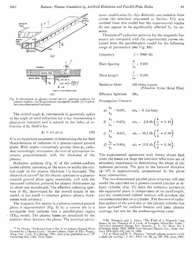
The magnetic line source i n a plasma-covered ground plane is approximated (Fig. 9j by narrow slit in a wiveguide t h a t radiates into a parallel-plate region ('l'Eol modej. 'The plasma losses are simulated by the resistive sheet between the plates. The terminal admit-
tance modification b\- thin dielectric and resistive films across the interface (discussed i n Section 111) was omitted from this model but the experimental results do not appear to be significantlp affected b>- its ab- sence.
TheoreticaP radiation patterns for the magnetic line source are compared with the experimental curves ob- tained from the parallel-plate model for the following range of parameters (see Fig. 10):
Frequency 1 9060 N C
Ii
x 0
Plate Spacing 0.692
I
x 0
Plate Length 0.769
Resistive Sheet 420 ohms/square (Filmohm Mylar Metal Film)
Effective Aperture 3810
Propagation Constant
x0
x, 0.691, ax0 0 (no loss)
0.694, d o 15.8 db A 0
1,
The experimental agreement with theory shows that when the losses are large the interface reflections are of secondaq- importance in determining the shape of the radiation patterns. The gain i n the forward direction (+=OO") is approximately proportional to the plane wave attenuation.
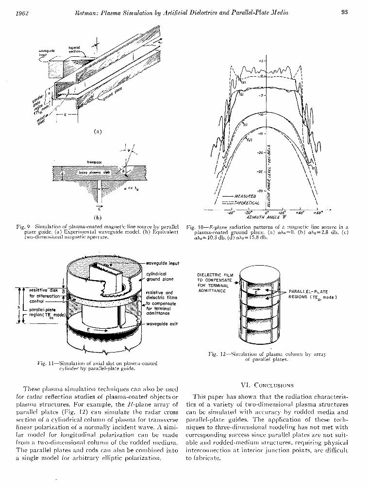
The two-dimensional parallel-plate structure will also model the axial slot on a plasma-covered circular or el- liptic c>-linder (Fig. 11 j since the radiation pattern i n the equatorial plane is independent of its axial length, and the constrained rodded medium will simulate the circumferential slot on a cylinder. The theoretical radia- tion pattern of the axial slot on the circular cylinder has been derived?g for uniform lossless and lossy plasma coatings, but not for the nonhomogeneous cases.
M. Sewstein and J. Jurye, "The Field of a Magnetic Lin: Source i n the Presence of a I.ayer of Comp!ex Refractive Index, Technical IZesearrh Group, Inc., SS-oset. Y., Sci. Iiept. No. 1
tract .AF041,645)-21]: Ju ly 1956. [Purchase Order SLIP 40000 from General Electric Co., under con-
29 J. I<. \Vait and E. kIientla, "Slotted cylinder antennas a.ith a dielectric- coating," J . Res. 3 B S , vol. 58, pp. 287-296; June,
Authorized licensed use limited to: IEEE Xplore. Downloaded on May 10,2010 at 19:00:04 UTC from IEEE Xplore. Restrictions apply.

i 5
Fig. 8-H-plane radiation patterns of an electric aperture in a plasma-coated ground plane. (a) Z=O (no plasma). (b) (c) (d)
Authorized licensed use limited to: IEEE Xplore. Downloaded on May 10,2010 at 19:00:04 UTC from IEEE Xplore. Restrictions apply.
Rotman: Plasma Simulation by drtificial Dielectrics and Parallel-Plate Media
( b ) Fig, 9-Simulation of plasma-coated magnetic line source by parallel
plate guide. (a) Esperinlental waveguide model. (b) Equivalent two-dimensional magnetic aperture.
dielectric
Fig. 11-Simulation of axial slot on plasma-coated cvlinder by parallel-plate guide.
These plasma simulation techniques can also be used for radar reflection studies of plasma-coated objects or plasma structures. For example, the H-plane array of parallel plates (Fig. 12) can simulate the radar cross section of a cylindrical column of plasma for transverse linear polarization of a normally incident wave. .I simi- lar model for longitudinal polarization can be made from a t~~o-dimensional column of the rodded medium. The parallel plates and rods can also be combined into a single model for arbitrary elliptic polarization.
Fig. 10-E-plane radiation patterns of a magnetic line source plasma-coated ground plane. (ai a-h0=0. (b j db
10.3 db. (dl 15.8 db.
Fig. 12-Simulation of plasma column b)- array of parallel plates.
93
( c ) in a
This paper has shown that the radiation characteris- tics of a variety of two-dimensional plasma structures can be simulated with accuracy by rodded media and parallel-plate guides. The application of these tech- niques to three-dimensional modeling has not met with corresponding success since parallel plates are not suit- able and rodded-medium structures, requiring physical interconnection a t interior junction points, are difficult to fabricate.
Authorized licensed use limited to: IEEE Xplore. Downloaded on May 10,2010 at 19:00:04 UTC from IEEE Xplore. Restrictions apply.

The relations between the propagation constant and terminal admittances for very lossy parallel-plate guides, techniques for improving the boundary condi- tions for rodded media, and wave propagation in these structures for negative indices of refraction are still be- ing explored. The use of glow discharge tubes, such as commercial fluorescent lights between parallel-plate guides, is also being studied as a means of simulating some of the nonlinear characteristics of the plasma me- dium.
APPENDIX
ELECTRICAL CHARACTERISTICS OF THE RODDED ~:IEDIA
The propagation constant and characteristic imped- ance of the rodded medium can be obtained by equating the transfer function for one section of this periodic structure to that for an equivalent continuous line of equal length.30 The transfer function matrix [Fig. 13 (a) is defined as
The transfer function matrix for a T section of the rodded medium [Fig. 13(b)] is of the form
a? sinh- I
2
and so
B sinh y f b (1 cosh yCb),
j 1
Z , 2Zt C sinh y f b (1 cosh y f b )
C)
Fig. 13--,4nalysis of rodded medium. (a) Transfer function matrix. (b) T section of rodded medium. (c) Equivalent section of con- tinuous lines.
The transfer function matrix for an equivalent section of continuous transmission line is
Equating corresponding terms in (39) and we get
cosh r,.b cosh rcb sinh ycb j Z ,
and
For the T section, (41) and (42) can be combined to give
Yfb tanh
z, z, Y r b
tanh 2
The complex propagation constant of the rodded media can be obtained from (41). Its characteristic im- pedance is then determined by (43).
A similar analysis can be made for a T section of the where b is the grid spacing, is the grid impedance, and rodded medium, leading once again to (41) for the prop-
are the propagation constant and characteristic agation constant. The characteristic impedance of the impedance, respectively, of the embedding medium. w section is given by
vo!. 97, pt. 3, pp. 1548; January, 1950. 3o J. Brown, "The design of metallic delay dielectrics," Proc. IEE ,
sinh y,b
sinh y rb z,
Authorized licensed use limited to: IEEE Xplore. Downloaded on May 10,2010 at 19:00:04 UTC from IEEE Xplore. Restrictions apply.

1942 Rotman: Plasnza Simulaiion by -.1rt<firiul Dielectrics and Parallel-Plate Media 95
Two cases of the T section analysis of the rodded me- Case 2 . Lossless Dielectric. Lossy Grids dium are of interest. In both, em is the relative dielectric constant of the embedding material, n is the effective j - E n , ; R~ +j-\-,;
2s
refractive index of the rodded medium, and Zo, Xoare E r n J ,
respectivel)? the free space characteristic impedance and wavelength.
Eqs. (41) and (43) become
Eqs. and (43) become
and ACKKOWLEDGMENT
The author is indebted to V. Karas for carrying sd/,b out the plasma simulation experiments, to C. E. Ellis
for calculating the attenuation of waveguidest to 11.
and to G. Forbes for assisting i n the calculations: B. S.
tan
Em T M b z, (46) Omura for computing the theoretical radiation patterns,
tan Karasik contributed editorial advice.
Authorized licensed use limited to: IEEE Xplore. Downloaded on May 10,2010 at 19:00:04 UTC from IEEE Xplore. Restrictions apply.