plant modification package no. 99-029 * a, entitled, 'aux feed … · 2012-11-18 · of piping...
TRANSCRIPT
NNuclear Power Business Unit PLANT MODIFICATION NO.: 99-029*A
PLANT LODIFICATION
INITIATION
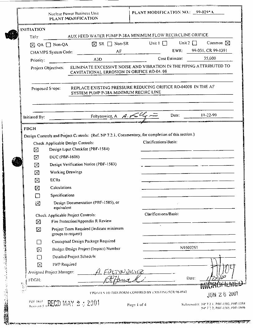
Titl:" AUX FEED WATER PUMP P-38A MINIMUM FLOW RECIRCLINE ORIFICE
Z QA F1 Non-QA Z SR [ Non-SR Unit I [] Unit 2 [] Common Z
CHAMPS Systcm Code: AF EWR: 99-031. CR 99-1391
Priority: A3D Cost Estimate: 35,600
Project Objectives: ELIMINATE EXCESSIVE NOISE AND VIBRATION IN THE PIPING ATTRIBUTED TO
CAVITATIONAL ERROSION IN ORIFICE RO-04. 08
Proposed S-ope: REPLACE EXISTING PRESSURE REDUCING ORIFICE RO-04008 IN THE AF
SYSTEM PUMP P-38A MINIMUM RECIRC LINE
Initiated By: Foltynowicz, A ,,4. --. Date: 11-22-99
FDGH
Design Controls and Project Controls: (Ref. NP 7.2.1, Commentary, for completion of this section.)
Check Applicable Design Controls: Clarifications/iasis:
0 Design Input Checklist (PBF-l1584)
DUC (PBF-1606)
Z Design Verification Notice (PBF-1583)
Working Drawings
ECRs
[] Calculations
[] Specifications
Design Documentation (PBF-1585), or
equivalent
Check Applicdble Project Controls: Clarificahons/Basis:
Fire Protection/Appendix R Review
[] Project Team Required (indicate minimum groups to request)
[] Conceptual Design Package Required
SBudget Design Project (Impact) Number N9500261
Detailed Project Sched.e _le__ __"_
IWP Required
Assigned Project Manager: /, "/'3cL'/ " .
". FDGIA: -. i• .-______ Date:4,-
.tPDATl 1 O r IiIS FORM COV.RED BY iX1SFING SCR 98-094.2 JU Z , L zo 1
R--. ~- 4 W ' paýNc I of 4 RPrcc(s) Ni7 2 1, PF-1 583. P1W-i:- R4
NP 7212. P131:.1 585. p
--

NUCLEAR POWER BUSINESS UNIT PLANT -IODIFICATION NO.: 99-09*"A PLANT MODIFICATION
PROJECT MANAGER - ESTABLISH PROJECT TEAM
Assigned Assigned Group Represented Team Member Group Represented Team Member
Radiation Protection D. LeClair
Fire Protection D. Foltynski
Installing Organization
Operations M. ':chug
S) stem Engineering J. P. Schroeder
QA J. Polacek
QC R. Geier
FDGH ConurreCe: Date:
PROJECT MANAGER Indicate any additional modification package infermation, if any: None
PROJECT NIANAGER/FDGII Indicate any clarifications or changes to design controls or project controls: /JLr (Note: FDGH approval required if design controls or project controls relaxed)
K�U4 4;�' Date: /2, '4
I PD. 11', M IIIIS I ORN-I (()Ai RID B1Y I', INIM, "S(R 9S-0942
-a 2 of 44RCN
•i Hxiin50 "4c'Rcftkcncc(-, NP 7 2 I t -1 III- I
NUCLEAR POWER BUSINESS UNIT PLANT MODIFICATION NO.: 99-029*A
PLANT MODIFICATION
PROJECT M,IANAGER - CONCEPTUAL DESIGN jCheck here if not required: E]
Provide a concise description of the conceptual design. List all attached documents which define the conceptual design. See
1 commentary in Nil 7.2.1 for additional guidance.
L-- None [] Attached
Li None [] Attached
[]None [] Attached
LI None [] Attached
I None F-1 Attached
Lii None -- Attached
D-] None Attached
n- None - Attached
L't)A'IE-S TO Ti uIS FOR2%i COVERI:ED BY EEXIS'I.NG SCR 98-09-12
PBF- 10i5 Revision 5 07,'14/9)
Page 3 of 4 R cfcrcnce(s)4 N1, 7 2 I. pI- 15,3. 1'9F-t I NP 7.2 2, Pi, i Sl.: P F-160,
xRI R:57147M
I
Conceptual Design Complete: -Project Manager Date
GROUP HEAD CONCEPTUAL DESIGN REVIEW AND ACCEPTANCE [Check here if not required: Z)
Review conceptual design. Attach comments on NPBU Document Review Comment Sheet (PBF-1622 or equivalent)
Crrnn Acceptance Signature Date Comments
Radiation Protcztion
Fire Protection
Installing Organization

I A NUCLEAR POWER BUSINESS UNIT PLANT MODIFICATION NO: 99-029-A
PLANT MODIFICATION
FINAL DESIGN REVIEWS
Review final d&,ign. Attach comments on NPBU Document Review Comment Sheet (PBF-1622 or equivalent)
ioupAcceptance Signature Date Comments
Radiation Protection ,_ )2_..) [-]eAttached
Fire Protection Engineer ,None [] Attached
Installing Organization
Operations
System Engineering
QA
QC
1 /,0- -x, i;- t o-27.'~
5- '2-2,0
. None
D None
-- None
-- None
LINonc --None
L] An.ached E] Attached
U Attached
[r-Attached
e F-Attached
e D Anached
i?�. /�/ Date:
PROJECT MANAGER - CLOSEOUT
Plant modification is complete, including submittal of all document updates in the Document Update Checklist (PBF-1606).
List all Work Order(s) used for installation:
Project Manager: .'z. -'-"�-- Date: r - Z -oo
Sl l/NUCLEAR INFORMATION M1ANAGEMENT
Microfihn the entire modification package.
ii
ul'l) 1, rts IO fis F'.)R\I COV', RLiF )BY EIXiSrING S( R 9S-(,,92
Nt07- I',5Pazwc 4 of 4 tdcrcncnL(s) N P7 2 1. 1l[t -14,3 PBF- I S I
NP'7 2 , PNI - I-I -; P11 ;-* '
- -- - - - -. w,-r� r
FDGH:
11
INDEPENDENT REVIEW OF INSTALLATION DOCUMENTS
All design and licensing requirements have been incorporated in the installation and testing document(s).
Reviewer: ?~b C'c. ~Date: & ~ 2o
FDGHI - RELEASE I All design controls have been properly implemented and the project has been appropriately reviewed. All necessary documents
are approved. This design is released for installation. Comments regarding release of this design are noted below:
A /Z

4i,
FINAL DESIGN DESCRIPTION MODIFICATION REQUEST 99-029*A
"* Wisconsin Electric Power Company, Drawing GLD M-217, Sheet 1. QA Classification Diagram Auxiliary Feedwater System QA Classification Diagram, Point Beach Nuclear Plant - Unit I & 2, Revision 11.
"* Bechtel Drawing P-103. Emergency Feedwater Pumps To Main Feedwater Lines 4" & 3"-DB-3, Revision 10.
"* Bechtel Drawing P-159, Aux. F.W. From Heating Boiler Cnds. Return & Pump Recirc. To Cnds Stg. Tank 6" & 3" JG-4 Unit 1.
"* ASME. Boiler and Pressure Vessel Code, Sy.,.tion III, 1977 Edition (with Winter 1978 Addenda).
"* Flowserve Pressure Reducing Orifice Drawing 103, 2" 600# Cast Stainless Steel Pressue Reducing Device, September 1, 1999.
"* PBNP Final Safety Analysis Report, Auxiliary' Feedwater System.
"* Design Basis Document DBD-01, Auxiliary Feedwater System.
"* EWR 99-031, AF Pump Recirculation Noise In The Control Room
"* CR 99-1391, SCAQ on Potential Common Mode Failure Mechanism Affecting Welds In AFW Pump Recic. Line.
"* Wisconsin Electric Power Company, Point Beach Nuclear Plant - RCE 99-081, "Socket - Weld Failures In Auxiliary Feedwater Pump Recirculation Piping".
"* Bechtel Specification No. 6118-M-6, Rev. 3, "Specification For Auxiliary Feedwater Pumps Point Beach Nuclear Plant Units 1 & 2 Wisconsin-Michigan Power Company, dated 10/28/68.
"* EPRI TR- 111188, "'Vibration Fatigue Testing of Socket Welds". Interim Report, December 1998.
"* EPRI TR-107455, "Vibration Fatigue of Small Bore Socket-Welded Pipe Joints", Final Report, June 1997.
DESIGN DESCRIPTION AND ANALYSIS
The proposed modification MR 99-029*A. replaces RO-04008 installed in the AF pump P-38A minimum flow recirculation line. % ith a new RO. The presently installed RO was accredited with causing flow induced cavitation, therefore, allowing for excessive noise and vibration in the AF piping system.
Page 2 of 7 Rev. 0

FINAL DESIGN DESCRIPTION MODIFICATION REQUEST 99-029*A
The proposed modification meets the- design, materials, fabrication, construction, and examination and testing standards of the existing installation. The proposed modification will be essentially a direct replacement for the components already installed and operational. The replacement RO will have the same function as the existing orifice RO-04008, which is to provide pressure reduction and act as a pressure boundary for the AT system piping.
A comparison of the mechanical and foy, perfomance characteristics of the existing vs. new RO indicates that the replacement RO is equal or better. The replacement RO will provide improved anti-cavitation characteristics, thus, will minimize hydrodynamic noise and vibration under liquid application.
The original design requirements for the RO are specified in the Bechtel Specification No. 6118M-6, Rev. 3, "Specification For Auxiliarv Feedwater Pumps Point Beach Nuclear Plant Units I & 2 Wisconsin-Michigan Power Company. dated 10/28/68.
T'nLh specification does not address design'construction specifics for this RO. It specifies that, "Each pump shall be furnished with a pressure reducing orifice to be used in conjunction with the on-off control valve in the pump recirculation piping. The orifice shall be provided with ended weld connections fo," installation in AF piping. If the flow through the orifice may cause erosion, special materials, such as 316 stainless s,eel, shall be used."
* The currently installed RO, was designed and constructed by the Byron-Jackson Company (BJCO) (MR 88-099). It was procured to a commercial program (not an Appendix B. QA, Program) and dedicated for its application.
The replacement RO was procured from the Flowserne Company under P.O.# 4500291375. to the requirements of the 10 CFR 50, Appendix B, QA Program. This includes among other QA requirements, a flow calculation to demonstrate that the orifice ,will pe-form as specified. A seisnmic analysis and report. to demonstrate that the orifice will operate during and after a seismic event was determined not to be required for this RO. This determination was performed by WE Seismic Qualification Group and is discussed in detail in the Safety Evaluation for this modification.
"The desi,!,n of new RO is different than the presently installed orifice. The existing RO uses inner orifice plates to control the flow and pressure drop across the orifice. The new RO works in a similar manner except that control of Ilo%% and pressure drop is accomplished by directing the flow over the series of close-fitting cylindrical stages, each constructed with expansion holes and intersecting circumferential channels that restrict the flow. This flow path of multiple restriction and enlargements reduces the pressure gradually across each trim cylinder, avoiding the sharp pressure drop typical to conv..entional. sinle-throttling orifice.
The replacement RO is containcd in a 2"- 600= ,ast stainless steel body (ASME A 351 Grade CF3A). RO's body is designed to the requirin!ents ot'ASME B31.1 and ASME B 16.34- 1996 .Edition. - design pressure is 1440 ps_-. thus. meeting the Pipe Class 2"-DB-3 requirements.
Paz 3 of 7Rcv. 0

FINAL DESIGN DESCRIPTION MODIFICATION REQUEST 99-029*A
A hydrostatic pr', ure test of the replacement RO shell was performed at the Flowserve facility in accordance w \SME/ANSI B 16.34. except that the test pressure was maintained for at least 30 minutes.
In addition to RO replacement, some of the existing piping associated with RO will also be replaced. The piping to be replaced is shown on Working Drawing SK-MR-99-029*A and includes the 90' piping elbow upstream of the RO-04008 to the upstream socket weld on the isolation valve AF-00027. This piping replacement is necessary in order to provide oversized socket welds. The replacement piping and RO will be joined by socket welds which are oversized in a 2/1 configuration. The oversized socket weld detail is shown on Working Drawing SK-MR-99029*A.
The design and construction materials requirements for AF piping are summarized in the Wisconsin Electric Design and Installation Guideline DG-M02. The piping to be replaced is classified as Pipe Class 2"-DB-3. This Pipe Class specifies carbon steel materials, however due to wear concerns the existing piping is stainless steel (ASTM A-312 Grade TP 316). Thus, replacement piping and piping components will be also stainless steel.
The replacement piping material for the proposed modification is ASTM A-312 Grade TP 316. The replacement piping fittings material is ASTM A-182 Grade F 304. The replacement piping and piping components meet the pressure and temperature ratings for Pipe Class 2"-DB-3.
Tfhe replacement RO is heavier than existing one, and it will add weight to the existing AF piping svstem. In addition, the replacement piping assembly will have a slightly different internal length of piping than the existing piping layout. However, face-to-face length of the replacement pipe spool piece will be exactly the same as the existing one:These differences between the existing and proposed piping configurations have been addressed by the Wisconsin Electric Co. (WE) analysis which have demonstrated ASME B 31. L!ompliance of the modified piping. Addendum A to Piping System Qualification Report WE-100070, Rev. I documents this evaluation.
In addition, the flow characteristic of the replacement RO and its affect on the associated plant calculations was evaluated. This evaluation was documented in Addendum A to Calculation No. N -91 -063, "P-LA & B Recirc Line System Characteristics". Rev.0 and Addendum A to Calculation No. N -- 91 - 069, "Impact of Higher Capacity Recirculation System for the Electric Motor Driven AFW Pumps". Rev. 0.
The results of this evaluation found that the slight differences in the flow characteristic between existing and replacement pressure reducing orifices is acceptable and does not significantly alter the above calculations results.
Components for proposed modification were procured as QA/Safety Related material.
Paue 4 of 7 Rev 0

FINAL DESIGN DESCRIPTION MODIFICATION REQUEST 99-029-A
None of the above changes is introducing a new, unknown equipment to PBNP. Furthermore, replacement components are passive in nature when the system is operational and will be designed. installed and tested in accordance with existing procedures and controls.
To implement this modification, the portion of the AF piping will be cut at the socket weld at valve AF-00027 and disconnected at the orifice's FE-04050A flange. This disassembly is shown on Sketch SK-MR-99-029*A. Piping. and pipe components removed will not be reused for this modification. The only exception is orifice's FE-04050 flange and its associated pipe stub up to 90* elbow. This assembly will be inspected and then reused. To assure high quality of socket welds, a re,)lacement piping spool piece (containing new RO) will be fabricated in the shop in accordanck- with details provided by Working Drawing SK-MR99-029*A.
Implementation of this modification will reduce the possibility for line noise and vibration when operating this line in the recirculation mode.
The proposed modification is located in the Control Building on Eleation 8', and adheres to the requirements of the Fire Protection E1valuation Report. A fire protection analysis, for the affected area, has been performed and the Fire Protection Conformance Checklist. PBF-2060 has been completed and approved.
Design pressure, operating pressure, design temperature and other pertinent design parameters for RO are specified in the Data Sheet attached to the P.O.4 4500291375.
No procedure changes result from this modification. This is a physical replacement of a RO and associated portion of the AF system. There will be no additional components added or operating modes changes that will require operating procedure changes.
Weldinig tbr this modification will be performed in accordance with welding procedures WP-7.
FME &%ill be practiced to avoid foreign material intrusion into the AFW system.
Health Physics (I IP) will determine the radiological requirements for the proposed installation.
NDE requirements for the Pipe Class affected by the proposed modification are specified in NP 7.4.3 and the original code of construction. USAS B31.1 - 1967. They require the finished socket %,elds to receive a Visual Examination (VT).
The affected existing wvelds have a history of failure, therefore, in addition to VT of the final socket xNelds. root welds will receive VT and Liquid Penetrant Examination (PT). Piping socket ,\elds shall be examined in accordance with ASNIE BS3 1. 1 - 1992.
To ensure equipment intended function %%hen returned to service foliowing the proposed modification, a post-modification test will be performed. The pont-modification test will cunsist "of:
Pace 5 of 7
Roe. 0

FINAL DESIGN DESCRIPTION MODIFICATION REQUEST 99-029-A
* initial service leak test , replacement RO performance test.
The proposed modification will be installed during the non-outage year 2000 time frame. Installation of this modification does not require Unit I or Unit 2 Shutdown. However, it will require entry into a seven (7) day LCO for the affected AF pump P-38A.
AF-27 will be relied upon to isolate the CSTs from the modified portion during installation. This valve is 1 500# class, globe valve that is socket welded. Backpressure on this valve is approximately 15 psig. which reduces the likelihood of leakage. If leakage does occur, it would be very -,mall, and flooding is not a serious concern. If the leakage prevents welding, than a contingency action (i.e. freezeseal) will have to be employed to isolate the leakage to allow welding to be completed.
Painting of the piping modified by the proposed modification is not required (stainless steel piping material).
DESIGN OUTPUT
The Installation Work Plan IWP 99-029*A will be prepared to identify installation requirements including pre-operational conditions, installation testing and post installation testing requirements. In addition, a 10 CFR 50.59 Safety Evaluation has been prepared to identify any CLB affects/changes.
The following calculations were prepared to address the proposed modification:
Orifice manufacturer's (Flowserve Co.) calculation.
Addendum A to WE Piping System Qualification Report WE-100070, Rev. I.
Addendium A to WE Calculation No. N-91-063, Rev. 0.
Addendum A to WE Calculation No. N-91- 069, Rev. 0.
The following Installation Work Plan is associated with this modification:
IWP 99-029*A, Aux Feed Water Pump P-38A Minimum Flow Recirc Line Orifice - Unit 0
The following working drawing is associated with this modification:
SK-MR-99-029*A. Auxiliary Feed\%ater System Orifice GO - 04008 Replacement. Unit I & 2.
Bill ot Materials (BONM) for IWF 99-029*A.
Pa,_,e 6 of 7 Rzc. 0
- .-. - . - - .-.-.-

FINAL DESIGN DESCRIPI -ON MODIFICATION REQUEST 99-n29"A
Fire Protection Conformance Checklist.. PBF-2060
10 CFR 50.59/72.48 Safety Evaluation. SE 2000-0055.
Page 7 of 7Rev. 0

NUCLEAR POWER BUSINESS UNIT MODIFICATION REQUEST CHECKLIST
OCUMENTATION UPDATE SHEET AND CLOS-OU-T CHECKiST k
Required For
NiA Acceptance Closeou: (Completion) (Submhiua!)
A- TRAI.- 1r". iG
x
x
x
MR NU,'vIBER 99-029"A (M'O9, if non-mod)
.Lssn Plans
Pant Sta-js Update.ust-in-Tirne Training
Training Handbook
4. Simularor Changes Initiated
3 FINAL DESIGN ORGANIZATION
i. Dravings
x
x
x
, x
x
x
x
x
xx
x
x
x
x
x
x
x
x
6.
S.
0
1�9.
I K
1�..
lJPDATES TO THIS FORM COVEREFD BY EXIS t:'-, G --R
a- Pen & Ink changes end DCNs initiated for Control Room Drawings - Logics. P&lDs, 499 series elementaries.
b. Pen & Ink changes and DCNs initiated for Work Control Center Drawings - P&IDs
c. Pen & Ink changes and DCNs initiated for I&C Drawings Reactor Protection and Safeguards Elementaries.
d- Mas.er Data Bcok - Control Room, Work Control Center, and Local Panel - PBF-2093
e. Drawing Revisions - PBF-1508
f. New Drawings - PBF- 1592
ly. Drawings Voided - PBF-1592
h. Working Drawings TransferredJVoided - PBF- 1592
Purchase Orders - (also contract numbers)
Specifications
Cornmnent Instruction NManuaNs (for issue, revision, deletion), PBF-1586
Cable and Raceway Data Schedule Revisions - PBF-0091
WERLDS Data Base Revision - Design Guideline DG-E08.
Envircnnmental and S-eismic Qualification Documentation Updates - Ref. NP 7.7. 1. NP 7.7.2.
FPER Revisions - NP 5.2.! 1
Upda:e Fire Protection manual.
Cacuiations added deleted I revised - PBF- 1608
FSAR - change; NP 5.2.6
f'ech-ical Specification - change: specify section(s) affected and change request number, i: known.
12
SEST COPY AVAILABLE.BF-1606
Revision 5 0(7/'2i9X
� 4 � c* - . - - -V -. ,. '7.. - -. � *
of -t Rcference(5): NP7 -

14,
F
MR NUMBER 99-029-A-X (NVO4, if non-mod)
X
X
x
x X
5.
6.
7.
S.
9.
11).
EOPs, ECAs, CSPs - PBF-0026a
Periodic CalLips - PBF-9920
Fire Protection Procedure - PBF-0026a
EOP Serpoints, EOP Instrument Uncertainty Calculations PBF-8001
Tank Level Book - PBF-0026a
Emergency Plan and EPIPs - PBF-0026a
X
X
x
X X
x
x x
x
X
x
X
x f ITr10. 1A. IOB)
ST: S. T C0 7 LAS' n f F-4 1505
x 7- 7771 ý-77ý7
OX
SNUCLEAR POWVER BUSINESS UNIT MODIFICATION REQUEST CHECKLIST
OCLU 'iENTATION UPDATE 5HEET AND CLOSEOUT CHECKLIST
SRequircd For
VA Acceptance Closeout (Completion) (Subminal)
!3. Report major changes to radwasze treatment sisterns with aniual FSAR update per PBNP Thch Spec 15.7.S.5.
14. EPIX Update - report MR changes to the EPIX Coordinator.
I ALARA Rev;iewv - s me_: minutes or re.;ie. document.
16. Report major chang-s to the containment aluminum inventory list with FSAR update.
17. DBD Revisions - PBF-1611
IS. PSA Models and Documentation - PBF- 1626
C. CHAMPS DATABASE
I. Equipment Ide"ification - additions assigned from CHAMPS
2. Permanent Labeling - labels on new equipment: PBF-9900
3. Temporary Labeling - labels on new equipment; PBF-2074
4. Equipment Record - update to CHAMPS coordinator specify\ change(s); PBF-9922
. Spare parts stocking and scrapping inputs into CHAMPS. PBF-9925, PBF-1023
6. Unused material removed from modification bin.
D. OPERATIONS
I. Abnormal Operating, Normal Operating, and Refueling Procedures - PBF-0026a
2. Operating Instructions and Checklists - PBF-O026
3. Alarm Response and R-MS Alarm Setpoint and Response Books PBF-0026a
4. Testing - TS? IT. ORT, other - PBF-0026a

IR NUMBER 99-029*A
(WO#, if non-mod)
OCUMENTATIOCN UPDATE SHEET AND CLOSEOUT CHECKLIST Reu'uired For
N/A Acceptance Cioseout (Completion) (Submittal)
E. MAINTENANCE I&C
1. Maintenance Procedures "Instructions - PBF-0026a
2. ICPs - PBF-0026a
3. Setpoint Document - PBF-8001
-4. Preventative Maintenance - initiate/revise CHIAMPS callups: PBF-9921:9920
5. Ensure station batteries' load profile changes are incorporated into the appropriate discharge test RMPs.
F. SECURIT'f
I. Security Procedures
2. Security Plan
G. ENGINEERING[MISC.
I. ISI Program
2. IST Program
3. Miscella-heous HX ECT.'Cieaning program
4. Reactor Engineering Instructions - change; specify section(s) affected.
5. Reactor Engineering Refueling Procedures - change; specify section(s) affected.
6. Software Control - specify system affected and softvare change request number.
7. Component maintenance programs.
8. Governing calculations and models (e.g., SW model, DC loading,
EDG loading,. piping analysis, structural loading, etc.).
H. OTHER (CHEM. HP, ETC.)
!. ECRs
1. ECR Final Resolution completed and appro, ed by FDGH.
2. ECR Implementation completed.
BEST COP', AVAILABLEPBF-1606 :1 ,sc: 7 •I•
x
x x
x
x
x
x
x
x x
x
x
x x
x
x
I mI
NUCLEAR POWER BUSINESS UNIT MODIFICATION REQUEST CHECKLIST
T Section
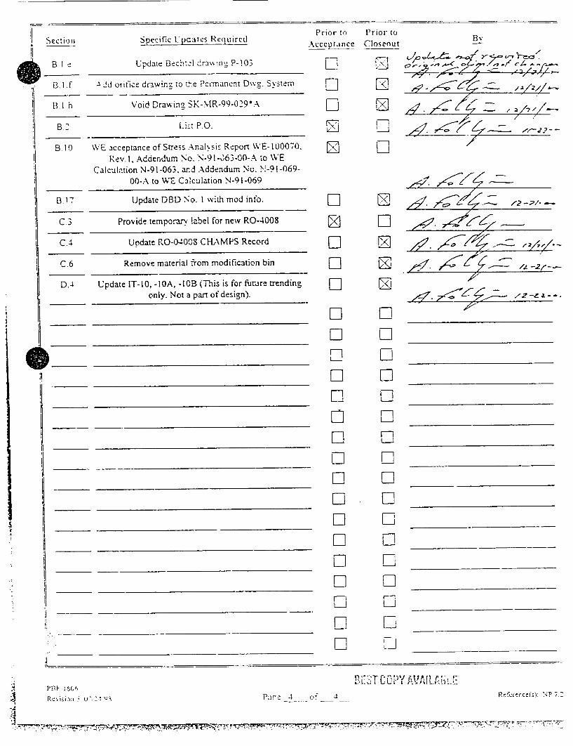
B.le
RI f
Prior to Prior to AcceD/ance ClosenutSpecific Lpcates Required
Update Bech:el dra% ing P-!03
A.d orifice drawing to zi-e Permanent Dvs. System
Void DrawinQ SK-MR-99-029*A
List P.O.
WE acceptance of Stress Anal,-sis Report WVE-l00070. Rev. I, Addendum No. N-91-0)63-00-A to WE
Calculation N-91-063, ard Addendum No. N-9!-06900-A to WE Calculation N-91-069
Update DBD No. I with mod info.
Provideý temporary label for new RO-4008
Uodate RO-04008 CHAMPS Record
Remove material from modification bin
Update IT- 1, -IOA, -lOB (This is for future trending only. Not a part of design).
B.1h
BlO
B.17
C3
C.4
C.6
D.-i
0__
IL -__ _ __ _ __ _
PEI Fsc u ~ :I~ t f7
ME`T C O'P'Y' AVI L A i, i :.!H.Rcfcrcrceds,: NP i '4
Li El
EL
0 Li
Li Li E]
17
D -i
Eli
D n
0
Li
LI Li LI Li Li Li Li Li Li
Z
L/\
II
D Li
D
Li
D
Fi
LI Fi
Li Fi
Li
Li Li Li
Li H Li Li
B
dz /
,Z2 ,- -•
10 CFR 50.59172.48 SCREENING AND SAFETY EVALUATION
Titie of Proposed Change. Test or Experiment:
SE y - cr06.6 SCR
Page I
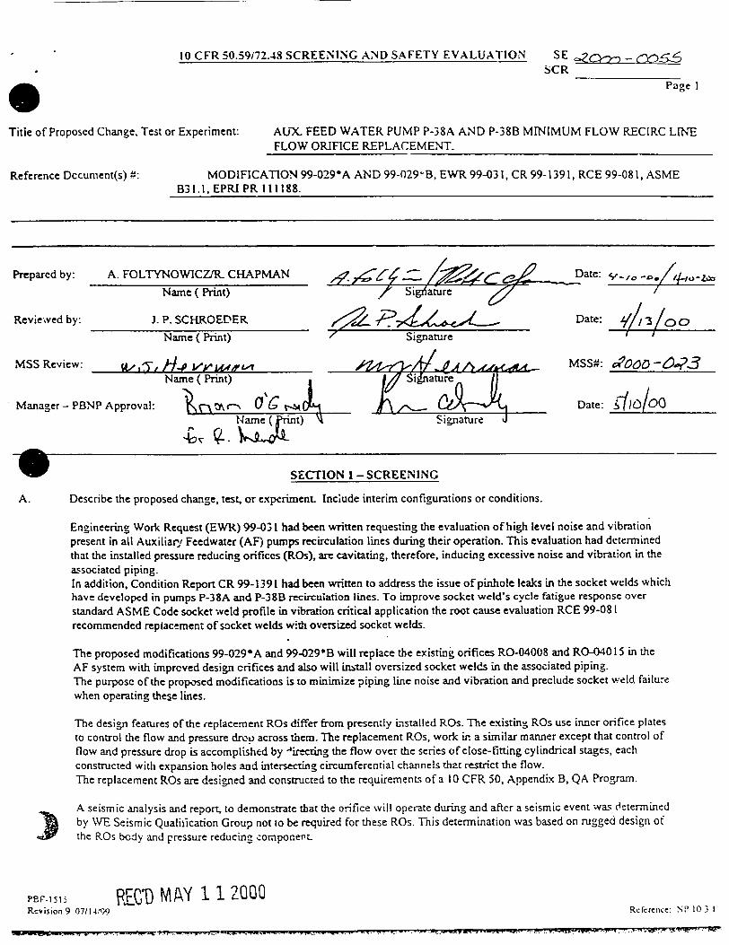
AUX. FEED WATER PUMP P-38A AND P-38B MINIMUM FLOW RECIRC LINE FLOW ORIFICE REPLACEMENT.
Reference Dccument(s) ": MODIFICATION 99-029*A AND 99-029-B, EWR 99-031, CR 99-1391, RCE 99-081, ASME B31.1, EPRI PR 111188.
Prepared by:
Reviewved by:
MSS Review:
A. FOLTYNOWICZ/R. CHAPMAN
Name (Print)
J. P. SCHROEDER
Name ( Print)
9',/, 5 Ham V( Wrint) Name ( Print)
' / Date: ." Sigiiature
_ _ _ _ _ _rDate:
7 SignatureZ /3 °o
MSS#: ¢rooo -6-?-3
Date: _i 0O0Manager - PBNP Approval:
-m
SECTION I -SCREENING
A. Describe the proposed change, test, or experiment. Include interim configurations or conditions.
Engineering Work Request (EWR) 99-031 had been written requesting the evaluation of high level noise and vibration present in all Auxiliary Feedwater (AF) pumps recirculation lines during their operation. This evaluation had determined that the installed pressure reducing orifices (ROs), are cavitating, therefore, inducing excessive noise and vibration in the associated piping. In addition, Condition Report CR 99-1391 had been written to address the issue of pinhole leaks in the socket welds which have developed in pumps P-38A and P-38B recirculation lines. To improve socket weld's cycle fatigue response over standard ASME Code socket weld profile in vibration critical application the root cause evaluation RCE 99-081 recommended replacement of socket welds with oversized socket welds.
The proposed modifications 99-0294A and 99-029*B will replace the existing orifices RO-04008 and RO-04015 in the AF system with improved design crifices and also will ins-tall oversized socket welds in the associated piping. The purpose of the proposed modifications is to minimize piping line noise and vibration and preclude socket weld failure when operating these lines.
The design features of the replacement ROs differ from presently installed ROs. The existing ROs use inner orifice plates to control the flow and pressure drco across them. The replacement ROs, work in a similar manner except that control of flow and pressure drop is accomplished by "irecting the flow over the series of close-fitting cylindrical stages, each constructed with expansion holes and intersecting circumferential channels that restrict the flow. The replacement ROs are designed and constructed to the requirements of a 10 CFR 50, Appendix B, QA Program.
A seismic analysis and report, to demonstrate that the orifice will operate during and after a seismic event was determined )•J• by WE Seismic Qualification Group not 1o be required for these ROs. This determination was based on rugged design of the ROs body and pressure reducing component_
PBF-1515 Rcvision 9 07/114f9)
FrE~'D MAY 1 12000Refeence: N' 10 3 I
a,. 7 1- Mm.--- Mt I I, N, _- _. .- MM.-C - -.. ý. N"T. F --- , - "-4 T 7 T 4;7"-- W LAU mw- -

10 CFR 50.59172.48 SCREENING AND SAFETY EVALUATION SE E
SCR
Page 7_ SECTION I - CONTINUATION
In order to install oversized socket w.;elds, piping associated wirh the replacement ROs will also be replaced. Replaced piping will
include the 90 deg. elbow upstream of the RO up to and including the upstream w.eld on the AF pumps recirculation line isolation
valve AF-27 for pump P-38A and valve AF-40 for pump P-38B.
The proposed modification will meet design, material and construction standards of the existing installation. The implementation
of the proposed modification, will not affect the overall performance of the AF system. operation or function of the AF pumps P
38A and P-38B and the ability of AF system to perform its intended safety functions.
Post modificai ,on testing will include a visual exam (VT) of all replaced piping socket welds. Piping welds will be
examined in ;rcordance with ASME B3 1.1 - 1992. Performance of this exam is required by both the original piping specification, Bechtel M--8, and the original code of construction, USAS B3 1.1- 1967. USAS B3 1. 1 - 1967 also requires that post modification
testing include an initial service leak test at normal system operating temperature and pressure. In addition, a functional test and
verification of the pressure drop and flow through replacement ROs will also be performed.
MR 99-029"A centrols the replacement of the RO-04008 and MR 99-029*1B controls the replacement ct the RO-04015.
The proposed modifications are scheduled to be installed with Unit I and 2 in Power Operation. A seven (7) day LCO for AF
system r *mps P-38A and P-38B will be required for each unit with the RCS above 3507F to install each modification. Upon
completion of each of the modifications, the new installed ROs will perform th" same function as the existing orifices RO-0400S
and RO-040 15.
B. List relevant current licensing basis (CLB) and Independent Spent Fuel Storage Installation (ISFSI)
licensing basis documents and sections.
i. FPER, Auxiliary Feedwater System, Figure 6.6 - 4a. I. FSAR Section 1.3, General Design Criteria. 3. FSAR Section 10.1, Steam And Power Conversion System. 4. FSAR Section 10.2, Auxiliary Feedwater System. 5. FSAR Section 14.1.9, Loss of External Electric Load. 6. FSAR Section 14.1,10. Loss of Normal Feedwater. 7. FSAR Section 14.1.11, Loss of All AC Power to the Auxiliaries. 8. FSAR Section 14.2.4, Steam Generator Tube Rupture. 9. TS Section 15.3.4. Steam And Power Cojiversion System.
10. TS section 15.4.8, Auxiliary Feedwater System.
C. Does the proposed change. test or experiment involve a change to any Technical Specification? (For the D Yes N
ISFSI, does the nroposed change, test, or experiment involve a change in the license conditions as
contained in the t-ertificat! )f Compliance?) if a change is required, briefly describe ',hat the change
should be and why ;t is required. lf"Yes," see NP 10.3.1 for guidance.
The proposed change does not affect the Technical Specification (TS) elements and requirements for the Auxiliary
Feedwater System The proposed change a!so does not affect any syst,±m that interface with the ISFSI Thus no TS
change is required.
BEST COPY AVAILABLE
Rcsion9 \,',R n P W,
SCR 2 Pac
SECTION I -CONTINUATION
Scroenine for 10 CFR 50.59 and 10 CFR 72.48 Applicability:
NOTE: If any question in Section I.D. I is answered "yes." complete section 2, "10 CFR 50.59 Safety Evaluation."
If any question is answered "yes, " the "no" answers do not have to be explained.
I. 10 CFR 50.59 Screening:
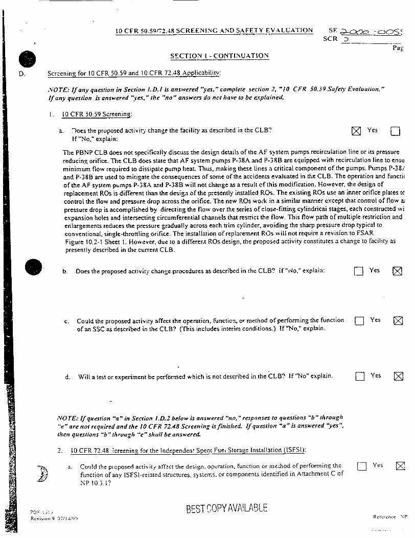
a. ;)oes the proposed activiry change the facility as described in the CLB? If "No," explain:
N Yes --
The PBNP CLB does not specifically discuss the design details of the AF system pumps recirculation line or its pressure
reducing orifice. The CLB does state that AF system pumps P-38A and P-38B are equipped with recirculation line to ensu
minimum flow required to dissipate pump heat. Thus, making these lines a critical component of the pumps. Pumps P-38; and P-38B are used to mitigate the consequences of some of the accidents evaluated in the CLB. The operation and functi(
of the AF system pumps P-38A and P-38B will not change as a result of this modification. However, the design of
replacement ROs is different than the design of the presently installed ROs. The existing ROs use an inner orifice plates tc
control the flow and pressure drop across the orifice. The new ROs wock in a similar manner except that control of flow a;
pressure drop is accomplished by directing the flow over the series of close-fitting cylindricai stages, each constructed wi
expansion holes and intersecting circumferential channels that restrict the flow. This flow path of multiple restriction and
enlargements reduces the pressure gradually across each trim cylinder, avoiding the sharp pressure drop typical to
conventional, single-throttling orifice. The installation of replacement ROs will not require a revision to FSAR
Figure 10.2-1 Sheet I. However, due to a different ROs design, the proposed activity constitutes a change to facility as
presently described in the current CLB.
b. Does the proposed activity change procedures as described in the CLB? if"No," explain:
c. Could the proposed activity affect the operation, Function, or method of performing the function of an SSC as described in the CLB? (This includes interim conditions.) If "No," explain.
d. Will a test or experiment be performed which is not described in the CLB? If "No" explain.
NOTE: If question "a" in Section i.D.2 below is answered "no," responses to questions "b" through
"e" are not required and the 10 CFR 72.48 Screening is finished. If question "a" is answered "yes", then questions "b"through "e-shallbe answered.
2. 10 CFR 72.48 "creening for the Independen' Spent Fue, Storage Installation (ISFSI):
a. Could the pioposed activity afftct the design. oopzration, function or me.hod of performing the
Function of any ISFSI-reiated structures, systems. or components identified in Attachment C of
NP 10.3.1?
BEST COPY AVAILABLE
SYes (Z
E]DYes [
Dt Yes (
L Yes F]
PP V-; 3 i 5 Rcy,'Niun 9 07114';QQ Relkrcncc NP
0 D.
10 CFR 50.59f72.48 SCREENING AND SAFETY EVALUATION

10 CFR 50.59172.4S SCREENING AND SAFETY EVALUATION S E 00 SCR
Page 4SECTION 1 - CONTINUATION
The Auxiliary Feedwater System is not a part of t:e ISFSI. Therefore the proposed activity does not affect the design, operation, function or method of perforriing the function of any ISFSI-related structures, systems, or components identified in Attachment C of NP 10.3. 1. The proposed nmodification affects the AF pump P-38A and P-383 recirculation lines. This recirculation lines supports the operation o,"these ptumps. The AF pumps P-38A and P-38B are not required and do not support any activities as.;ociated with the dry cask storage facility. The proposed modification will not affect any system(s) related to the loading/unloading of dry cask fuel assemblies. Therefore, the proposed modification does not change the facility as described in the [SFSI licensing basis.
NOTE. If any of questions "b" through "e" in Section ;.0.2 is answered "yes," complete Section 3, "10 CFR 72.48 Safety Evaluation." If any question is answered "yes," the "no" answers do not have to be e,,xplained.
b. Does the proposed activity change the facility as described in the ISFSI licensing basis? If "No," explain.
c. Does the proposed activity change procedures as described in the ISFSI licensing basis? If "No," explain.
d. Could the proposed activity affect the operation, function, or method of performing the function of an SSC important to safety as described in the ISFSI licensing basis? (This includes interim conditions.) If"No." explain.
e. Will a test or experiment be performed which is not described in the ISFSI licensing basis? if "No," explain.
BEST COPYAVAILAB, Eh L E'UL1
,�,f Ii'
0 (J7114,0
D Yes No
Y Yes N, o
D Yes No
Yes No
.ctcrcn•., N'P 10 _ I

NUCLEAR POWER DEPARTMENTSAFETY EVALUATION REPORT Page 6
Section 2 - Continuation
A comparison of the mechanical and performance characteristics of the replacement ROs versus the existing ROs indicates that replacement ROs are either identical or better. The replacement ROs will provide impro, ed flow characteristics, prevent cavitation ard minimize pipe vibration, thus eliminate secket weld failure. The review of the properties of the materials selected for these modifications indicates that they are either equivalent or bette: than presently installed materials. The components are passive in nature when the system is operational and will be designed, installed and tested in accordance with the existing procedures and controls. Therefore, they do not introduce any new failure mechanisms not already considered for the area. FME and PMT will be implemented to ensure the proper operation of the system upon completion of the modification. Based on the above, the proposed modification will not increase the probability of occurrence of a malfunction of equipment important to safety previously evaluated in the CLB.
3. Could the proposed activity increase the radiological consequences of an accident, event, or malfunction of equipment important to safety previously evaluated in the CLB?
E- Yes Z,7Analyses for accidents that result in the loss of Normal Feedwater require AF flow of 200 gpm to affected Unit. Fail safe closure of AOVs, AF-4007 for pump P-38A and AF-4014 for pump P-38B ensures that there is a high-pressure feedwater supply to the steam generators in order to maintain water inventory for removal of heat energy from the reactor coolant system in the event of inoperability or unavailability of the main feedwater system. If these AOV valves fail to close, the restriction orifices RO-04C08 and RO-04015, respectively will limit the amount of feedwater recirculated back to the CST. Addendum No. N-91-063-0-A to Calculation No. N-91-069 shows that in that event, P-38A and P-38B will deliver approximately 110 gpm to - ,ir respective SG. which exceeds the assumed value in the accident analysis. In addition, the proposed activity does not create new radiological release mechanisms or paths. Based on the above, the proposed activity does not increase the radiological consequences of an accident, event, or malfunction of equipment important to safety previously evaluated in the CLB.
4. Could the proposed activity create the possibility of an accident or-event of a different type than any '] Yes previously evaluated in the CLB?
The proposed modifications will have the same piping configuration, installing equivalent or better components. As discussed in Section 2 of this SE, the replacement ROs will be tested and evaluated to demonstrate suitability for this application. The modified recirculation lines will function identically to the currently installed recirculation lines. A technical evaluation of the replacement ROs indicates that these ROs are more suitable (no cavitation) for this application than the presently installed ROs. Therefore, the proposed activity will not create the possibility of an accident or event of a different type than any previously evaluated in the CLB.
5. Could the proposed activity create the possibility of a malfunction of equipment important to safety [] Yes of a different type than any previously evaluated in the CLB?
E N
Z7N
The proposed modification will replace the existing components with equivalent, replacement components or supeior components evaluated and tested for this application. The non-affected piping trains will be maintained in service to ensure operation of the AF system_ Once the new equipment is physically installed and modification testing complete, each recirculation line will be fuictionally tested (PMT) to ensure they function as designed. The oversized socket welds and replacement ROs do not change the function, method(s) of operation, or introduce any new credible failure mechanisms to the AF pumps P-38A and P-38B and their recirculation lines. The replacement ROs consist 0 globe valve body with anti-cavitation tim- Valve bonnet and stem/plug are not included. The flow passage area of replacemr ROs could possibly lead to reduced pump recirculation flow during operation of the pumps with SW since particles/debris ir the SW could be filtered by the RO's trim. To preclude this, the ROs design directs flow through the outside of the trim. The outside cartridge of the trim contains the smallest size flow passage area. The flow passage area then become progressively
PBF1 515 BEST COPYAVAILABLE Revision 9 07114.;99 Reference NP 10
•.• • ,t,,. ,zk--•,• r-¢ ••,,21•_ t•.-:¢'PI .... Z W,••,
N,

2. Could the proposed activity increase the probability of occu'T-rence of a malfunction of equipment important to safety previously evaluated in the CLB?
Yes 7Yes
"The CLB discusses the use of the AF system pumps P-38A and P-38B to ensure that adequate feedwater is supplied to the
serviced Steam Generators for heat removal. The proposed modification is replacing the existing orifices RO-04008 and RO-04015 with new orifices that support the
operation of the AF pumps P-38A and P-38B. During accident conditions, the safety related functions of each of the AF pump recirculation line orifice is as follows:
I. Provide passive flow resistance in the AF system pump recilculation line: thereby establishing the required recirculati,
flow and pressure drop from AF system pump discharge pressure to CST pressure. These ROs must provide adequate flo%'
prevent !ow-flow instabilities and excessive fluid temperature rise in the AF system pumps.
I. Limit the recirculation flow in the event that the recirculation control valve fails to close during AF system pump
operation. 3. Passively maintain the AF system pressure boundary integrity. The replacement piping assemblies existing piping configuration will not be changed as a result of this modification.
The replacement ROs are contained in a 2"- 6004, cast stainless steel body (ASIME A 351 Grade CF8M) designed to the
requirements of ASME B 16.34 - 1996 Edition. Their design pressure is 1440 psig, thus, meeting the Pipe Class 2"-DB-3
requirements. A hydrostatic pressure test of the replacement ROs shell was performed by the Vendor in accordance with
ASEIE/ANSI B 16.34, except that the test pressure was maintained for at least 3.) minutes which exceeds the 10 minutes
requirement of the Code. The replacement ROs are slightly heavier than the existing ones. This difference in weight has been addressed by the
Wisconsin Electric Co. (WE) analysis which have demonstrated ASME B 3 1.1 compliance of the modified piping.
Addendum A to Piping System Qualification Report W'E-100070, Rev. I documents this evaluation. In addition, the flow
characteristic of the replacement ROs and its affect on the associated plant calculations was evaluated and documented in
Addendum No. N-91-063-00-A to Calculation No. N -91 -063, "P38A & B Recirc Line System Characteristics", Re- 0 a
Addendum No. N-91-069-00-A to Calculation No. N - 91 - 069, "Impact of Higher Capacity Recirculation System for tht
Electric Motor Driven AF Pumps", Rev. 0. The results of this evaluation found that the slight differences in the flow
characteristic between existing and replacement ROs do not significantly alter the affected calculations results and are
acceptable.
BEST COPY AV,2ILAE
RKc'. Ion 9 .' I,,
r r
U-
10 CFR 50.59/72.48 SCREENING AND SAFE 1 Y EVA LUATION SEý .o0 - '7_'3SS
Pag
SECTION 2 - 10 CFR 50.59 SAFETY EVALUATION
A. I. Could the proposed activity increase the probability of occurrence of an accident or event previously D Yes Z evaluated in the CLB?
The proposed activity to replace existing ROs affects AF pump P-38A and P-38B recirculation lines. These ROs are not discussed in the CLB in any manner as a contributor or initiator to an accident or event scenarios alrcady evaluated. However, they do function to support the operation of the AF system pumps P-38A and P-33B and these pumps are invo, in such accidents as "'Loss of Normal Feedwater", "Loss of All AC Power to the Auxiliaries", "Loss of External Electric Load", and "Steam Generator Tube Rupture". The proposed activity of replacement of the RO-04008 and RO-04015 does effect the actuation of the AF system or its operation as presently evaluated in the CLB. The proposed modifications will meet design, material and construction standards of the existing installation. The changes that will be implemented by the proposed modification will not affect the overall performance of the AF System and operation or function of the AF pump 38A and P-38B to perform their intended functions. Based on this premise. there is no increase to the probability of occurrence of an accident or event that has been previously analyzed in the CLB.
The implementation of the proposed modifications will require for one motor-driven AF pump at a time to be taken out of service for a period of seven (7) days. This is a!1owed by the requirements of the Technical Specification Section 15.3.4 C. This Section allows two (2) unit operation where one motor-driven pump may be out-of-service for up to seven (7) days.
I 5• cA'Xo -ooS55
Paf
Section 2 - Continuation
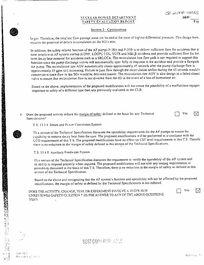
larger. Tlerefcre, the smallest flow passage areas are located at the zone of highest differential pressure. This design feamr
reduces the potential of debr.s accumulation on the RO's trim.
In addition, the safety related function of the AF pumps P-38A-and P-3SB is to deliver sufficient flow for accidents that ar
time sensitive to AF system s-a.'up (LONF, LOOP), I OL, SGTR and MNLB accidents and provide sufficient flow for Ion
term decay heat removal for accidents such as a SBLOCA. The recirculation line flow path is not required to support this
function since the pump discharge valves will automatically oper fully in response to the accident and provide a flowvpath
the pump. The recirculation rine AOV automatically closes approximately 45 seconds after the pump discharge flow is
approximately 95 gpm a-ni increasing. Failure to pass flow through the recirculation orifice during the 45 seconds would I
conservative since flow to the SGs would be delivered sooner. The recirculation line AOV is also design as a failed closed
valve to ensure that recLrculation flow is not diverted from the SG in the event of a loss of instrument air.
Based on the above, implementation of the proposed modifications will not create the possibility of a malfunction equipm
important to safety of a different type than any previously evaluated in the CLB.
6. Does the proposed activity reduce the margin of safery dfined in the basis for any Technical
Specification?
- Yes F
T.S. 15.3.4 Steam and Poer Conversion System
"-1,,s section of the Technical Specification discusses the operability requirements for the AF pumps to ensure the
capability to remove decay heat from the core. The prorosed modifications will be performed in a-cordance with the
LCO requirements of this T.S. The proposed modifications have no effect on CST level requirements in this T.S. Therefo
there is no reduction in the margin of safety defined in this section of the Technical Specifications.
T.S. 15.4.9 Auxiliary Feedwater System
Tlis section of the Technical Specification discusses the requirement to verify the operability of the AF sy-.tem and
its ability to respond properly when ;equired. The proposed modification will not alter any testing requirements or
periodicity discussed in the basis of this T.S. Therefore, there is no reduction in the margin of safety as defined in this
section of the Technical Specification.
Based on the above and recognizing that the AF system's function and operability will not be affected by the proposed
modifications, the margin of safety as defined by the Technical Specifications is not reduced.
DOES THE ACITVTEY, CTHA&NGE, TEST, OR E.XERIMaNT DTVOLVE A 10 CFT• 50.59
UNPREV.IE WED SAFETY QUE--ION ? (IS IHE ANSWER TO ANY OF TH ABOVE QUESTIONS
YES?)
SYes F
BE.ST COY, , .' - .__-I
R,.:. , 0 7
NUCLEAR POWER DEPARTNlENT SAFETY EVALUATION REPGRT
1

10 CFR 50.59172.43 SCREENING AND SAFETY EVALUATION SE,- -•,C
SECTION 2 - 10 CFR 50.59 EV.ALUAIrION SL.UMM LARY
B. The summary section should contain three brief paragraphs (no more than one page total), including: 1) Description of the
proposed change including in,-!rim configurations. 2) Justificat~on logic for the answers to the safety evaluation questions,
and 3) Conclusion (i.e., is a USQ or Technical Specification conflict involved.7)
The proposed modifications 99-029*A and 99-029"B will replace orifices RO-04008 and RO-04015 in a AF system with
improved design orifices. In addition: oversized socket welds will be provided in the associated piping. The existiag orifict
were cavitating, therefore inducing excessive- -:-is, vibration and socket welds failure in the piping.
The implementation of the proposed modifications w.l require for one motor-driven AF pump at a time to be taken out
of service for a period of seven (7) days. This is allowed by the requirements of the Technical Specification Section
15.3.4 C. This Section allows two (2) unit operation where one motor-driven pump may be out-of-service for up to
seven (7) days.
The orifices AF system orifices RO-04008 and RO-04015 are not discussed in the CLB in any manner as a contnibutor or
initiator to an accident or event scenarios already evaluated in the CLB. However, these orifices support the operation of ta
pumps P-38A and P-38B which are required to mitigate some of the CLB analyzed accidents.
The proposed replacement will meet design, material, construction and testing standards of the existing installation and wi.
degrade the overall performance, operation or function of the AF pumps P-3SA and P-38B. Therefore, the puv.ips will be a
perform their intended safer.t functions. The analysis included in the MR 99-029*A and MR 99-C29*B design packages ar
post installation testing in the work plan ensure that the AF pumps function as designed. The AF system does no, participa
radiological release mechanisms for the PBNP, and no new radiological release mechanisms or paths are created. Based or
the proposed activity will not increase the probability of occurrence of an accident or the radiological consequences of an
;.ccident or malfunction as previously evaluated in the CLB. Also, the proposed activity will not create the probability of a
accident of a different type than any previously evaluated in the CLB.
The installation work plan included precautions to ensure that no other safety related components were affected during the
installation. With the completion of the orifices replacement, t .'pumps functionality will remain the same. No equipment
degraded by this installation, thus the probability of occurrence of a malfunction of equipment important to safety as previ
evaluated in the CLB is not increased.
The proposed modification will replace the existing components with equivalent or superior components, evaluated and te
to demonstrate suitability for this application. The modified system will function identically to the current installed system
replacement ROs will provide improved flow characteristics and will prevent cavitation damage, thus minimize pipe vibra
under liquid application and associated socket weld failure. The replacement ROs do not change the function. method(s) o
operation, or introduce any nev. credible failure mechanisms to the AF pump P-38A and P-3SB recurculation line.
The recirculation line flow path is not required ,o suppcrt AF system in its response to the design basis accidents-since the
pumps discharge valves will automatically qpen fully in response to the accident and provide a flopath for the pump.
Failure to pass flow through the recircu!ation orifice due to potential of SW debris accumulation on zhe RO's trim would 1:
conservative since flow to the SGs would be delivered sooner. Therefore, this activity will not create the possibility of a
malfunction of equipment important to safety of a different type than any previously evaluated in the CLB.
T.S. 15.3.4, "Steam and Power Conversion System" and T.S. 15.4.8, "Auxiliary Feedwater System" discusses the require
to verify the operab`iiirv of the AF system and its ability to respond properly when required, they do nut discuss margin of
safety.
In conclusion, based on the justification above, the proposed modifications MR 99-029*A and NIR 99-029*B to replace R
4003 and RO-4015 do not introduce an unievie d safety question and do not involve a change to the Technical
"Specifications..
BEST COP'(A AI B, LE nj on 7
NLCLEAR P',\ ER UUSINESS UN'KIT
DESIGN VERIFICATION NOTICE
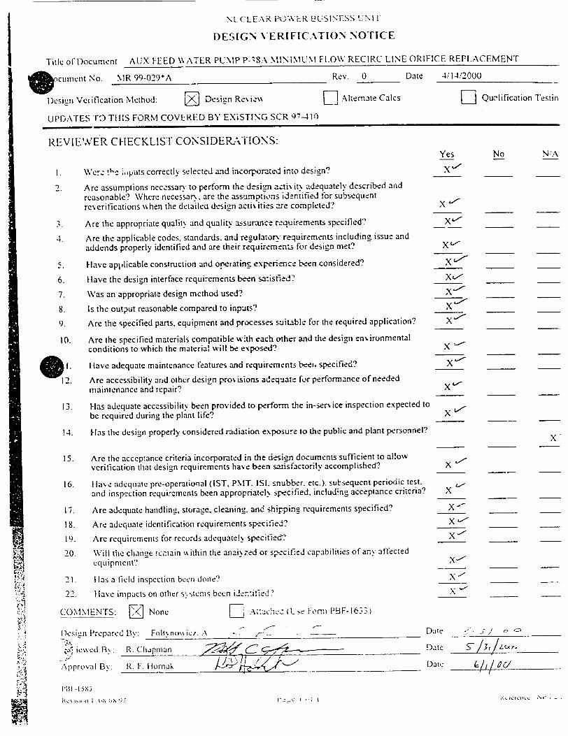
Title of Document AUX FEED WATER PUMP P-3SA MINIMUM FLOW RECIRC LINE ORIFICE REPLACEMENT
.cument No. MR 99-029*A Rev. 0 Date 4/14/2000
Desigrn Verification Method: Design Reviv, • Alternate Calcs [- Quw'lification Testin
UPDATES TO THIS FORM COVERED BY EXiSTING SCR 97-410
REVIEWER CHECKLIST CONSIDERATTIONS: Yes No N:A
I. Wet:'- :.,puts correctly selected and incorporated into design? X "
2. Are assumptions neczssary to perform the design .-cti, iv. adequately described and
reasonable? Where necessar,. are the assumptions identified for subsequent reverifications lshen the detailed design acti\ ities are completed? X L."
3. Are the appropriate quality and quality assurance rzquirements specified? X'"
4. Are the applicable codes, standards, and regulatory- requirements including issue and addends properly identified and are their requirements for design met? X
5. Have applicable construction and operating experience been considered? X
6. [lave the design interface requirements been satisfied? X
7. Was an appropriate design method used? X •
8. Is the output reasonable compared to inputs? X _ __
9. Are the specified parts, equipment and processes suitable for the required application? X_ "
10. Are the specified materials compatible ,:th each other and the design enN ironmental conditions to which the material will be exposed? X
I. I lave adequate maintenance features and requirements beei, specified? X
12. Are accessibility and other design provisions adequate for performance of needed maintenance and repair? X
13. Has adequate accessibility been provided to perform the in-sen. ice inspection expected to be required during the plant life? X
14. Has the design properly considered radiation exposure to the public and plant personnel? X
15. Are the acceptance criteria incorporated in the d.:'sign documents sufficient to allow verification that design requirements have been satisfactorily accomplished? X
16. Ilave adequate pre-operational (IST, PMT. ISI. snubber. etc.). subsequent periodic test.
and inspection requirements been appropriatel. specified, including acceptance criteria? X
17. Are adequate handling, storage, cleaning. and shipping requirements specified? X -
18. Are adequate identification requirements specified? X '
19. Are requirements for records adequate!% specified? X'
20. Will the change !cmain %% ithin the analyzed or specified capabilities of any affected equii pment?
X•
21. 1 las a field inspection been done' X_-__
22. lave impacts on other s,. stens been iien:ified? X "_
COMMENTS: F/1 None F_ .- .-ach.c (1-sc Form PBF-1633
fDcsien P~repared By: Foltv flo\• i. A . -- __ Date . I / -.
Sj ieced B\.: R. Chapman . CDatc - 1. _.,o,_.
Approval B\: R. F. Hornak Daie
S I'Ml- 1516
Si', on 1 0,1X 7_

PBF-.I 5ý.X
Rcvmiun 6 03'3 i,q9 Pfaue I ot 12
NUCLEAR POWER .31 ISINESS UNIT
DESIGN INPUT CHECKLIST
Fication or Temporary Modification Number: 99-029*A
Aux. Feed Water Pump P-38A Minimum Flow Recirc. Line Orifice
INSTRUCTIONS: Consider the basic functions of each stricture, system, and component, (SSC), when answering the questions. The
designer shall caeck the appropriate box for each design input or section. All inputs that apply to the design shall be explained. The
explar'tion ma) be documented on this checklist or in the design summary. The reviewer shall review the checklist, and any differences
between the d.-.signer and the reviewer should be addressed. This checklist addresses most design concerns, but is not all encompassing.
Any additional concerns should be addressed in the design summary.
(Updates to this form covered by SCR 97-411.)
APPLIES TO DESIG"
YES NO
A. General codes, standards, regulatory requirements, and design criteria.
1. Are any of the PBN? FSAR general design criteria applicable? (Reference FSAR, Section 1.3.
Identify and address design criteria as appropriate.)
Review of PBNP FSAR for applicable GDCs identified the following applicable GDCs: 1,2 5, and 42.
2. Are any design requirements contained in commitments affected? (Refeience CLB database and the E Safety Evaluation/Screening associated with this change.)
SE 2000-0055 was performed to evaluate this modification's impact on the design requirements
contained in the CLB.
3. Meet State of Wisconsin Administrative Code requirements? (Refer to iLHR 41.42, PSC 114, and
other sections as appropriate for requirements.)
,4. Meet existing DNR permits or require DNR approval? (Contact WE Environmental Department.) El z
5. Consider the effect of design and accident conditions, such as pressure, temperature, fluid chemistry, and radiation on components, including internal elastomers and material coating compatibility. fz El (Changes in design parameters may impact Environmental Qualification.)
6. rncorporate new types/models of equipment not presently used at PBNP? El .
7. Affect accessibility of any equipment? Consider interim conditions, future maintenance, and
in-service inspection. (Reference CIMs and dra%,inus for manufacturer's clearance requirements.)
8. Require penetrating a barrier? (Reference NP 8.4.11.) D
:_4 9. Consider operating experience from PBNP and industri events. (Reference DG-G04 for operating
experience reviews and NPRDS, NODII.. CHAMPS. INPO Ke,,v.ords, or other databases.) El
DESIGN INPUT CHECKLIST
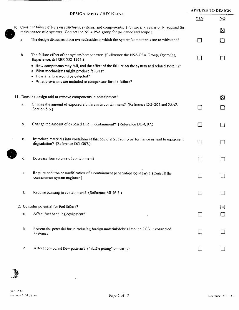
10. Consider failure effects on structures, systems, and components: (Failure analysis is only required for maintenance rule systems. Contact the NSA-PSA group for guidance and scope.)
a. The design discusses those events/accident, which the system/components are to withstand?
b. The failure effect of the system/components: (Reference the NSA-PSA Group, Operating Experience, & IEEE-352-1975.)
"* How components may fail, and the effect of the failure on the system and related systems? "* What mechanisms might produce failures? "* How a failure would be detected? "• What provisions are included to compensate for the failure?
II. Does the design add or remove components in containment?
a. Change the amount of exposed aluminum in containment? (Reference DG-G07 and FSAR Section 5.6.)
b. Change the amount of exposed zinc in containment? (Reference DG-G07.)
c. Introduce materials into containment thaL could affect sump performance or lead to equipment degradation? (Reference DG-G07.)
Sd. Decrease free volume of containment?
e. Require addition or modification of a containment penetration boundary? (Consult the containment system engineer.)
f. Require painting in containment? (Reference MI 36.3.)
12. Consider potential for fuel failure?
a. Affect fuel handling equipment?
b. Present the potential for introducing foreign material/debris into the RCS .;r connected systems?
c. Affect core barrel flow patterns? ("Baffle jetting" cncerns)
PBF-153. R:,% Ision t.. U 1 ji, Pa e 2 0" 1 1,
APPLIES TO DESIGN
YES NO
E]
LI LI D [0
El
El
El
El
EL
7I
El
El
LI
LI
LI
LI
LI
LI
LI
LI El
El
El
El
Rclcrclicc !' 7 2 '

DESIGN INPUT CHECKLIST
, Mechanical requirements. (Contact Mechanical Design Ergineering for guidance.)
I. H -ve applicable ASME Boiler & Pressure Vessel codes or other standards been identified?
(Reference the applicable specification. In addition, safety-related components should be reconciled
with DG-M 16. and QA components should be reconciled with ANSI N45.2.)
2. Affect or add components/systems to ASME Section XI class 1,2, or 3 equipment? (Refcrence PBNP
CHAMPS, CBD dra~vings. and IST Coordinator. If YES, follow NP 7.2.5, Repair,"Replacement
Program.)
3. Require State of Wisconsin Administrative Code permitsiapprovals'? (Reference NP 7.4.9, Wisconsin
Administrative Code for Boilers and Pressure Vessels or the Authorized Inspector.,
4. Consider component performance requirements such as capacity, rating, output?
5. Consider hydraulic requirements such as pump net positive suction heads, allowable pressure drops,
allowable fluid velocities and pressures, valve trim requirements, packing/seal requirements?
6. Provide vents, drains, and sample points to accommodate operational, maintenance and testing needs?
. 7. Require service water? (Both essential and nonessential service water loads are modeled, and load
changes mrst bc evaluated. Contact the SWAP Coordinator.)
8. Require the addition of check valves? (Reference DG-M13 for selection guidance.)
9. Require and evaluate any additional loading on instrument or service air, circ, fire protection, or
demineralized water, or other system?
10. Evaluate any additional loading on HVAC systems or affect xentilatior flow during or after
installation? (This will require an EQ review for potential updates to EQSS. EQML & EQM,*R.)
II. Require insulation? (Reference WE specification PB-4S5 for insulation, and NP 1.9.10 for asbestos
control.)
12. Require lubrication? (Reference Lubrication Manual.)
13. Require an independent means of pressure re!ief? (Rýft.rence B3 I 1.)
PHI .? ýX C, U) -.*5 4
APPLIES TO DESIG.
YES NO
[]
1:1
LI LI
LI
LI
LI
LI
r, '• 3 U - 1

OESI(;N INPUT CHECKLIST
14. Affect the assigned s:,stem design pressure or temperature?
15. Invu've cobalt-laden materials int3 the RCS or into s% stems that supply the RCS? (Reference
NP ,1.2.29, "Source Term Reducton Program.")
16. Are new materials and their coatings plating compatible wvith system chemistry and disposal systems?
C. Electrical requirements. (Contact Electrical Design Engineering for guidance.)
1. Consider design conditions such as ampacity, voltage drop?
2. Consider component and system performance requirements, such as current, voltage, or power?
3. Consider rcdunddncy, diversity and separation requirements of structures, systems and components?
(Reference DG-E07 for separation of electrical circuits.)
4. Comply with protective relaying requirements of equipment and systems'?
5. Selection ofovercurrert devices for proper protecwion and coordination? (Reference DG-E04 ýor
selection of molded case circuit breakers.)
6. Affect available fault current at any bus?
7. Assure that all added cables meet fire retardancv requirements? (Reference FPER Section 4.1.8,
IEEE 383.)
8 Be compatible with existing electrical insulation and -%iring?
9. Affect ampacity of existin,4 cables?
10. Maintain UL (or equiva!ent) listings?
11. Alter the voltage harmonic distc.nion c,. ntent or ch-.ane the non-linear loading (i.e.. the addition of
switching poser supplies, the ahitration of me circui's po% cr tactor, etc.) on a vital or scasitive
instrument bus?
.',) Add nivw racc.Navs? (Ret'crccic UGj-F03 for elcc::,a ' a,. siiii and PG-F02.ý
APPLIES TO DESIG,"
YES NO
[] D
EJ
LI [
LII [
[] [I
LI [
[] [
VI I F-1 584 Kc.',isioinO 03/3 ,'9cQ
4
E
i�ckrU1CP,-• ý_ e -,,1 ! -

13 0 14
15
16
17
I:
2
2
D.
DESIGN INPUT CHECKLIST
Add cables to existing electrical racexays?
Be routed through fire wrapped raceways?
* Affect the station grounding or lightning protection system?
Make any vital circuit susceptible to ground?
7. AffeL* emergr.,:cy diesel loading? (Reference DG-E06 for diesel load change evaluation.)
8. Add more station battery loading?
9. Add load to a vital bus?
0. Add load to a non-vital bus?
I. Be compatible with service transformer capacity?
Instrumentation and control requirements. (Contact I&C Design Engineering for guidance.)
I. Consider design conditions such as pressure, temperature, fluid chemistry, amperage, volta;e?
2 Have the instruments been properly selected for the application?
3. Have sufficient instruments for operators to monitor the process?
4. Have appropriatf instrument scales?
5. Have the instruments, control switches, and indicating devices been appropriately located for human
factors (both for operations and maintenance)? (Reference DG-GO I.)
6. Have alarms for off-normal conditions?
7- Be capable of or require remote and'or local operation"
/.J
I'M-FI 584
ý.C% l'i,.1 ") 0361,3 -
APPLIES TO DESIG,
YES NO
El M] El z
Li
El El
EL LIz
LIz
LIz
F-I
[] [
[] [
[] [
[] [
L] [
KC ickrelicc N P" "J-C 5 0 i2
DESIGN INPUT CHECKLIST
8. Be capable of or require manual ard'or automatic operation? 0 9. Require calibration and maintenance requirements for the instruments to be specified?
10. Have specified the instruments with proper range and accuracy?
11. Address solid state vulnerability to RFI?
PBF-1584
Re',ision 6 03131V9o
APPLIES TO DESIGN"
YES NO
L 0
E!
El
rz [
L.
LI
El
LI
Refeicr.cc NP 7
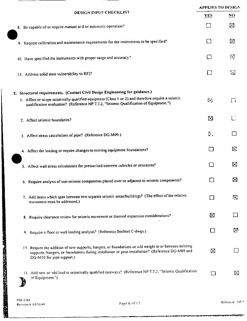
E. Structural requirements. (Contact Civil Design Engineering for guidance.)
I. Affect or scope seismically qualified equipment (Class I or 2) and therefore require a seismic
qualification evaluation? (Reference NP 7.7.2, "Seismic Qualification of Equipment")
2. Affect seismic boundaries?
3. Affect stress calculations of pipe? (Reference DG-M09.)
4. Affect the loading or require changes to existing equipment foundations? S 5. Affect wall stress calculations for pressurized concrete cubicles or structures?
6. Require analysis of non-seismic components placed over or adjacent to seismic components?
7. Add items which span between two separate seismic areasbuildings? (The effect of the relative
movement must be addressed.)
8. Require clearance review for seismic movement or thermal expansion considerations?
9. Require a floor or wall loading analysis? (Reference Bechtel C-dwgs.)
I'). Require the addition of new supports, hangers, or foundations or add weight to or between existing
supports, hangers, or foundations during installation or post-installation? (Reference DG-M09 and
DG-MI0 for pipe support.)
II. Add new or -idd load to seismically qualified raceways? (Reference NP 7.7.2, "Seismic Qualification
-. of Equipment.")
Page 6 of 121

DESIGN INPUT CHECKLIST
12. Modify, attach to, or locate within the proximity of masonry block walls? (Reference IEB 80-11 0 Block Wall Program.)
13. Require core drills, expansion anCiors, or re-bar cuts? (Reference DG-CO I for expansion anchor design and installation.)
14. Cre, -.- an external or internal missile hazard?
1 Cns~der wind and storm loading on external structures?
j, --,a; , protection from high energy line break jet? (Refer to FSAR Appendix A.2.)
17. Consider dynamic requirements such as live loading, vibration, and shock/impact?
F. Programs
1. ASME Section X! and QA considerations:
a. Affect IST acceptance criteria or calculations? (Contact Component Engineering.)
b. Require classification of new components? (Reference DG-G06 for system, component, and part classification.)
c. Affect QA-scope systems or boundaries? (Contact Site Programs Engineering Support for Q-List.)
d. Require special personnel/equipment qualifications not proceduralized at PBNP (i.e., underwater welding)?
e. Require material certification or other certification to ensure quality equal to or better than the affected SSC? (These requirements need to be specified in the specification or purchase requisition.)
f. Have all design requirements, such as pressure or current rating, been reviewed against lot descriptions or been specified on purchase requisitionslspecifications?
2. Fire protection considerations:
a. Affect the Fire Protection manual?
PBF- 1584
Revision 6 03/31/o9
APPLIES TO DESIGN"
YES NO
El
El
E-
Ml
El
LI
Page 7 of 12
0
J
Rec:('Cllcc. "',F . -'

APPLIES TO DES'S,
YES NODESIGN INPUT CHECKLIST
b. Affect fire protection requirements? (Reference Section 8.4 of the FPER.) I c. Affect access to a fire zone. fire protection equipment or Appendix R safe shutdown
equipment? (Reference FPER Section 8.4.3.1.)
d. Affect fire protection system performance? (Reference FPER Section 8.4.3.1.3.)
e. Wil, ane change affect the existing fire protection features, exemption reqt-ests, or regulatory commitments listed in zhe Fire Hazard Evaluation(s) of an Appendix i safe shutdown fire zone in FPER Section 5.6?
f. Based on Tables 6.7-1 to 6.7-4 and Figures 6.6-1 to 6.6-8P and 6.9-1 to 6.9-2.d, will the change add to, delete from, or revise the listed systems and comp..inents? (Reference FPER Section 8.4.3.2.)
Orifice replacement is within an Appendix R flow boundary, however, it will not affect the capability to safe shutdown the reactor.
g. Increase permanent combustible loading in a room? (Reference FPER Section 8.4.3.1.4.)
h. Open a fire barrier? (Reference NP 8.4.11 and Fire Barrier Drawings WE PBL-218 p SI'ee-s 1-20, FPER Section 8.,,.3.1.2.)
If any questions b through h are applicable, an evaiuation must be performed using the FPCC checklist, PBF-2060 per Section 8.4.3 of the FPER.
3. Flooding protection considerations:
A flooding analysis should be performed if any of the following questions are applicable and answered yes. (Reference Section 4.3 of DG-C02.)
a. Modify potential flooding sources or add new potential flocding sources to a flood zone and tl~ereby increase the direct and/or indirect flooding vulnerability of essential equipment?
b. Degrade existing flood barriers or flood mitigation fea:ares piuj bi,.ng unanaiyzed pathway for flooding to propagate? (Reference Section 3.2 of DG-C02.)
c. Involve the opening of potential flood sources anyw here at the station? (Installation procedures need to address inadvertent flooding. Reference DG-C02. Section 4.4.)
d. Reduce the capacity to iolate or cope with flood;ng? (Reference Sect. 4.2 of DG-C09.)
C. Change plant drainage backfill requirements?
PTFI -1584
Rev'iion6 0.'13, 1 Pae 8 of 12
LI
EL
LI
LI
E]
LI
LI
RC!CrCiCC N.P
-.-- ., w1or ý--
[a

DESIGN INPUT CHECKLIST
f. Locate essential equipment or supporting systems \•here it would be susceptible to flooding?
(Flood'ng conditions ma, also impact Environmental Qualification.)
4. Environmental considerations:
a. Be subject to adverse en,. ironmental conditions during storage or construction? (Reference
NP 9.5.2.)
b. Require freeze protection or affect existing freeze protection?
c. Locate safety-related or post accident monitoring equipment in a HARSH environment?
(Reference NP 7.7.1.)
d. Require Environmental Qualification (EQ)? (Reference NP 7.7.1 for EQ qualification.)
e. Be attached to an EQ system.'component? (This will require an EQ review for potential updates
to EQSS, EQML & EQMR. Reference EQ master list.)
f. Change environmental parameters (e.g., pressure, temperature, radiation, humidity)?
(Reference NP 7.7.1. "Environmental Qualification of Electrical Equipment." p 5. Radiation Protection (RP) and ALARA considerations: t,4 eference DG-G03, "ALARA Consideration
Guidciate fur Design & Installation.)
The areas mentioned below are normally within the RCA, but radiological concerns should be
considered for SSC outside the RCA also.
a. Affect any SSC in an RWP required area- a contaminated area, or a radiation area, including
opening of a system that may be a radiological concern?
b. Will the change generate excessive rad~%aste or highly radioactive/contaminated waste?
c. Remove any plant equipment from a potentially contaminated system (including BOP
systems)?
d. Result in an anticipated increase in operationai or maintenance exposures?
e. Result in an expected exposure of greater than I Rem for any individual during installation of
the change?
Pill, -1 53-t RC6,iionO 01,""I C; P2Z o (t" I2
APPLIES TO DESIGN
YES NO
IzZ
L I
0 L
0 L
El 0
[] [
LI
LI
LI
LI
LI
R C I Crc n C2 MI -

ArrLItIiU LkJ LiUN
DESIGN INPUT CHECKLIST YES NO
f. Result in an anticipated collective exposure of greater than 2 Rem for the installZtion of the
change?
If questions d, e, or f apply and are answered yes, then an ALARA review shall be performed.
(Reference NP 4.2.3, "ALARA Review Procedure.")
6. Chemistry considerations:
a. Require or affect established chemistry limits? (Contact system engineer and review chemistry
procedures.)
b. Require any routine chemical analyses? (Contact system engineer and review chemistry El procedures.)
c. Require chemical additives? (Contact PBNP Chemistry.)
d. Do new fluids/chemicals need to be evaluated for TRI (Toxic Release Inventory), CHES,
critical applications, or special disposal requirements? (Contact Chemistry/Chemical [] 0 Engineering.)
'Installations I. Installation requirements/plant conditions have been determined? EJ
2. Consider test and inspection requirements, including the conditio.;; under which they will be
performed? (Reference NP 7.4.1 for pre,,sure test requirements, NP 7.4.3 for post-maintenance and
modification NDE requirements, NP 1.2.5 for special test procedures, arid OM 4.2.2 for in-service
tests.)
3. Have post-installation acceptance criteria been properly specified to test the intended function of the
component(s)/system?
4. Comply with all WE lifting and rigging requirements? (Reference WE Safety Manual, PBNP Safe El 0 Load Path procedures, and NP 8.4.7.)
5. Require special handling, shipping, or environmental conditions for storage or construction?
(Ref• rence NP 9.5.2 for material storage.)
6. Consider transportability requirements such as size and shipping weight limitations. E
)7. Require spare parts or special non-standard items or tools? El Z
PB 0-15 31 Rcv.i,:on 6 03131/99 Page 10 of 12 Reference NP 7

DESIGN INPUT CHECKLIST
8. Will any added components introduce chemical contaminartts to the system? (i.e.. preservative coating o on valves. coz rigs on weld iod can also introduce contaminants)
9. Consider persoinel requirements and limitations, including the: qualification and number of personnel available for plant operation, maintenance, testing and inspection, and permissible personnel radiation exposures'
10. Operational requirements under various conditions, such as plant startup, normal plant shutdown, plant emergency operation, special or infrequent operation. and system abnormal or emergency operation.
a. Require new procedures or procedure changes? (Reference NP 1.2.5.)
b. Potentially impact other systems, components, or structures during installation?
c. Present installation impacts on plant.uperations (i.e., fire watches, etc.)?
II. Access and administrative requirements for plant security: If any security requirements are applicable, notify Security.
a. Create an opening >96 in.- in any wall, ceiling, or other barrier?
, b. Require work within 20' of fence?
c. Affect security equipment and documents, including those containing safeguards information? (Contact Security for design development requirements and design concurrence.)
d. A ffcct access controls?
12. Safety requirements:
.i. Affect safety equipment and thereby create personnel hazards (i.e., remoal of handrails)?
b. Introduce hazardous material into the plant? (Reference NP 1.9. 1.)
c. Affect evacuation routes or escape provisions from enclosures?
d. Meet OSHA regulations? (Reference \..,. Electric Safety Manual and OSHA 29 CFR 1910.)
Rc iRion6 03.;319Pa L |we II of 12
APPLIES TO DESIGW'
YES NO
Li
El
El
El
El
E]
El
El
Ret'orcncc NP 7 '

DESIGN UNPUT CHECKLISTAPPLIES TO DESIGN
YES NO
x� �1\9 5 igncd by:
Reviewed by:
j C
pHI -I i84
Rkien- fl A) ;13 P'.
Date: 47 57- 3/-Oo:
Date: s11
1 -~ Mcmicek 'NP 7 2'
C C 7-
PaL, - 1'-' o t- I ?

99�O29*A 10
INSTALLATION WORK PLAN
0OR PROCEDURE F-1
I \P NUMBER:
PBNP %.PI
WORK 0
FOR MO
[NS-1 AL
Aux Fe
RDER WORK PLAN
DIFICATION # MR 99-029*A , WO # 9919511
LATION WORK PLAN TITLE
ed Water Pump P-38A Minimum Flow Recirc. Orifice
UNIT 0 E QA-SCOPE
Originator .
Reviewer
Final Design Group Ilead7r
Quality Engineer C
Installation r' Group Head
F-1 NON QA-SCOPE
Da'e 0 "' Z•,o
Date 3*/Zc t--•
Date
Date /
Datc '57tF- e~l
%Lmanuc r Operations or DSS Date -. Q -.-- CO
NOTE: Chanmes to this work plan must dn-ne % 'th the concurrence of the
rcspnsible or team enuinee. and the installation surpek isor, or as delineated xithin the 1WVP,. DG -G02 .5
Revision I
�t�$cc
Check As Applicable
9NSALATONWOK LA
IF "
I -rage kt 0

NUCLEAR. POWER BUSINESS UNIT I\VP e9-029*A
INSTALLATION WORK PLAN WORK PLAN FEBRUARY 19, 2000
AUX FEED WATER PUMP P-38A MINIMU*I FLOW RECIRC LINE ORIFICE UNIT 1 &2
1.0 SCOPE
1.1 The scope of this installation work plan is to replace the portion of the existing line 2"- BD-3, including pressure reducing orifice RO-04008. The replaced piping and RO will be welded back utilizing oversized socket welds.
1.2 The purpose of this modification is to reduce piping line noise and vibration when operating Auxiliary Feedwater (AF) pump P-38A in the recirculation mode. The presently installed pressure reducing orifice (RO) is cavitating, therefore, allowing for excessive noise and cavitation induced pipe vibration. The purpose for oversized socket welds is to offer a significant high cycle fatigue improvement over standard ASME Code socket weld in vibration-critical application.
1.3 The approach of this installation is as follows:
1.3.1 Pre-fabricate new section of pipe as shown on sketch SK-MR-99-029*A.
1.3.2 Isolate and drain the affected piping.
1.3.3 Remove portion of the existing line 2"-DB-3.
1.3.4 install new sections of line 2"-DB-3.
1.3.5 Perform VT and PT exams on all new welds.
1.3.6 Functionally test the mini-recirc. line to verify operability.
1.3.7 Perform inservice leak check of new/modified piping and welds.
1.4 This installation is QA-scope work.
QA Scope Clarification:
The piping downistream of RO-04008 is non-QA scope.
1.5 Installation of this IWP will be performed during the Reactor being in any operating condition. The pumep P-38A will be out of service uinder a seven (7) day LCO. No other AF pump can be out of service.
1.6 This modification wil! not affect ar,%v ASME Section XI pressure boundaries.
PaLe 2 of1 8

NUCLEAR POWER BUSINESS UNIT INSTALLAI-ON WORK PLAN
AUX FEED WA'lATER PUMP P-38A MINIMUM FLOW
RECIRC LINE ORIFICE Ui N 1 & 2
IWVP 99-029*A WORK PLAN FEBRUARY 19, 2000
1.7 Support Requirements
1.7.1 Operations: Support to install and remove danger tags, system draining, and
post maintenance and operability testing.
1.7.2 NDE Group: Perform visual (VT) and liquid penetrant (PT) examinations
where specified in this IWP.
1.7.3 Security: Performs fire watch duties as directed by Operations.
1.7.4 QC: Support as required.
1.7.5 Engineering: Supuort NDE evaluations and post maintenance testing.
RE: Alex Foltynowicz Pager: 5518 Home Tel. No. 686-0098
1.7.6 Construction:
a. Perform erection and removal of scaffolding, as required.
b. Perform removal and installation of piping and supports.
c. Prepare as-built sketches of modified piping configuration.
2.0 PRE-INSTALLATION REQUIREMENTS
2.1, References:
2.1.1 Working drawing:
2.1 2
a. SK-M•.-99-029*A, "Auxiliary Feed\vater System Orifice RO - 04008
RepiLcement. Unit I & 2.
Vendor/Contractor drawing:
a. Flowserve Corporation drawing of the replacement orifice.
Pa 12 ,o '

NUCLEAR POWER BUSINESS UNIT INSTALLATION WORK PLAN
AUX FEED WATER PUMP P-38A MINIMUM FLOW
RECIRC LINE ORIFICE UNIT I & 2
IWP 99-029*A WORK PLAN FEBRUARY 1). 2000
Responsible Engineer has assured that all references listed above are approved and the
applicable requirements have been incorporated into the IWP. The references are either
with the Installation Group, attached, or are readily available to the Installation Group.
RE ,,2 Date - //- c o
2.1.3 Applicable Codes and Standards:
a. USAS B31.1 - 1967
b. ASMEB31.1 - 1992
2.1.1 Supplemental Procedures:
a. MI 32.1
b. MI 32.8
c. MI 32.9
d. NP 1.9.6
e. NP 1.9.9
f. NP 1.9.13
g. NP 1.9.15
h. NP 8.4.10
i. NP 8.5.2
j. PBF-9142
k. NDE-451
I. NDE-700
m. \VP-7
Flange and Closure Bolting
Guidelines for Opening Piping Systems
Scaffolding Erection
Plant Cleanliness, Storage, and Inspection Program
Transient Combustible Control
Ignition Control Procedure
Danger Tag Procedure
Exclusion of Foreign Material from Plant Components and Systems
CHAMPS Equipment Database I -:c and Control
Bolting-Torque Arid Loading
Liquid Penetrant Weld Examinatic:.
Visual Weld Examination
Welding Procedure for Stainless S; -- Is Group P-8 GTAW
Pipe Diameters Over 1- OD
Pao." 4 of 18

NUCILEAR PO)WER BUSINESS UNIT INS IALLA-ION, WORK PLAN
IWP 99-029*A WORK PLAN FEBRUARY 19. 2000
AUJX FEED) WATER PUNIP P-SSA M'INIMIUM FLOW RECIRC I-INE ORIFICE UNIT l&-2 _ _ _ _ _ _ _ _ _ _ _
2.2 Backaround Rcfcrences (those references not needed to perform work):
2.2.1 Drawings:
b. Bechtel Drawing P-103, Stress Isometric of Emergency Feedwater Pumps to Main Feedvvater Loines 4" & 3)"-DB-3
2.3 Installation Preparation Activities
A Bill of Material (BOM) is attached to this IWP or is included on the Working Drawing.
The Responsible Engineer has assured that all materials on the BOM are on site, available for the modification, and QA released.
New CHAMPS label for RO-04008 is required and has been requested.
The RE/IS has assured that all-of the above Installation Preparation Activities are comple'te.
RE/I S__ Date ?-/I-C
2.4 Pre-Installation Discussions
A pre-installation discussion with the lrnstallation Group representative, tile Tes'ing Group representative, and the Acceptance Group representative has
been performed.
RE/IS c __. ________ Date _ -,1-__
A field N•alkdown has been performed, if necessary, to verify that all aspects
of the procedure may be ki_,-focmed as intended.
IS . Date • "[ (-o)
P' Cgc '-) 1 •
2.3.1
2.3.2
2.3.3
2.4.1
2.4.2
a. Bechtel Drawing M-217, Sh. 1, P&ID of Auxiliary Feedwater System

NUCLEAR POWER BUSINESS UNIT INSTALLATION WORK PL AN
IWP 99-029*A WORK PLAN FEBRUARY 19. 2000
AUX FEED WAlIER PUMP P-38,\ MINIMUM FLOW RECIRC LINE CRlF` iSA_ . UNIT I & 2
--.4.3 A -ommitment has been obtained from Security to support fire watch requirements. Record the responsible group below.
/ Fire WVatch Support Group ,-)
2.4.4
Date /o
Foreign material exclusion (FME) shall be controlled per NP 8.4.10, Exclusion of Foreign Material from Plant Components and Systems, and PBF9158, FME Checklist.
RE1 ;lS , -- Date /1,-2.--z,6.
2.5 PersonnL! Sae"cn'Conceri s
The following preccuti -: . -,rsonnel safety requirements are recommended for this IWP:
2.5.1 Caution should be exercised when lifting or rigging components.
2.5.2 This installation will take place-in an area of increased fire awareness. Installation personnel shall take precautions against fire hazards.
2.5.3 Aux. Feedwater pump P-38A minimum recirculation line does not have drain connections. To allow this line to drain, metering orifice's (FE-04050A) downstream flange will be broken open. Safety caution of Ml 3? -, Guidelines for Opening Piping Systems shail be utilized.
The Installation Supervisor is aware of the above listed safety concerns.
Date _1o- 21-uc,
2.6 Identification of Permits Required
Work Order # 9919511 for this IWP has been written and submitted to CHllAMPS. The Work Order number has been recorded on the I\VP covcrshee,.
P,, 0 Il. '
2.6.1
is

NUCLEAR POVW-R BUSINESS (;Ni.
IN'STALLAT!ON \\ ORK PI..\N
1WP 99-029*A WORK PLAN
FEBRLiARY 19. 2000
AIAX FEED WATER P1. NIP P 13A -\IINI'MIJ.\I FLOWV RECIRC LINE ORIFICE U -NITI &,2
2.6.2 Ignition control permit is required for welding and shall be obtained by the
Installation Supervisor w,,hen needed.
The Installation Supervisor has assured that all necessary permitb lor this installation will be obtained.
is _ _ _ _ _ _ _ _ _ _ _ _ _ _ _ Date I e ~- 7
2.7 Pre-Installation Work
NOTE: The following work will not affect or be connected to anN
system that is either operating or in senrice and therefore it
can be started before Release for Installation.
2.7.1
2.7.2
2.7.3
Using the referenced Working Drawing. prepare Contractor Welder Travelers for all new welds.
Note: During pre-fabrication process perform the
fo!!owing root weld examinations in accordance
with Step 2.7.3: 1. Liquid penetrant weld examination. 2. Visual weld examinat~en.
Pre-fabricate piping assembly, including replacement orifice
RO-04008. in accordance with the Working Drawing SK-MR
99-029"A.
Perform visual examination (VT) of all pre-fabricated piping
root welds in accordance with NDE-700. In addition. perform
liquid penetrant examination (PT) of all pre-fabricated piping
root welds in accordance with NDE-451. The acceptance
criteria for piping welds are ASME B3 1.1 - 1992 and Working
Drawingt SK-MR-99-029*A.
CE/Date
C E/Date
VS a'Exam 7., Sat. I nsat.
PT Exam JýSat. - Unsat.
Note: If an miesat inspection condition is identified, NDE
%,till not sign off this step until the appropriate
e'.aluatihn and /or re,,Nork along with, re..inspection
has been accomplished.
Nl)[-P atc
P I, , _ k

NUCLEAR POWAER BUSINESS UNT N INSTALLATION WORK PLAN
IWVP 99-029*A WORK PLAN FEBRUARY 19, 2000
AUX FEED WATER PUMP P-3SA MININIUM FLOW RECIRC LINE ORIFICE UNIT 1 &2__ _ _ _ _ _ _ _ _ _ _ _ _
2.7.4
Note: After pre-fabrication process perform the following weld examinations in accordance with Step 2.7.4:
1. Visual weld examination.
Perform visual examination (VT) of all finished welds in accordance with NDE-700. The acceptance criteria for piping wvelds are ASME B3 1.1 - 1992 and Working Drawing SK-MR99-029*A.
VT Exam
IP at. E1 Unsat.
Note: If an unsat inspection condition is identified, NDE will not sign off this step until the appropriate evaluation and /or rework along with re-inspection has been acccmplished.
.1'e" NDE/Date
2. Olt I 2.8 Operational Installation Prerequisites
This installation will be performed during the Reactor being in any operating condition.
Establish twice per shift fire rounds per OM.3.27, Protection of Safe Shutdown/Appendix R Equipment.
Enter applicable LCO for P-38A. AF system pump being OutOf-Service.
flU:it 11tI
OPS/Date
NOTE: The following step indicates a recommended Danger Tag Series. This may be altered depending on the plant conditions as determined by the DSS.
BESTCCOPYAV D.I.ABLE P.c X CI
2.8.1
2.8.2
2.8.3
PILc Xof, I

NU-('LEAR POWER BUSINESS UNIT INSTALLATION WORK PLAN
IWP 99-029"A WORK PLAN
FEBRUARY 19, 2000
AUX F-EED WVATER PUMIP P-38SA NIINIMNIM FLOW RECIRC LINNE ORIFICE tUN IT I & 2
2.8.4
2.8.5
2.8.6
2.8.7
Prepare a Danger Tag Series for the equipment listed below. DO NOT HANG the tags until instructed to do so in Section 3.0.
a. Valve AF-00027, Pump P-38A Mini Recirc Outlet, CLOSED
b. Valve AF-04007, Pump P-38A Mini Recirc Control, CLOSED
c. Pump P-38A Electric Motor, DE-ENERGIZED
Isolate, and Danger Tag P-38A, AF system pump.
Obtain Ignition Control Permit, PBF-0068.
Date ]./,i]do Time d 7W: 5 1,,.e"
Release For Installation
All of the above operational installation prerequisites have
been met and it is acceptable to proceed with the installation.
DSS4(M IT Date L14 0 Time L)• I
All other installation prerequisites have been met including
performance of a pre-job brief with all involved personnel, as
required.
RE/'IS - .
,_jX
Date "/l//i C-'
Pav'o 9 o " 1 I
.il t OPS/Date
2.8.8
is

NUCLEAR POWER BUSINESS UNIT IWP 99-029*A
INSTALLATION WORK PLAN WORK PLAN FEBRUARY 19, 2000
AUX FEED WATER PUMP P-38A MINIMUM FLOW
RECIRC LINE ORIFICE
LUNIT I & 2
3.0 INSTALLATION
3.1 QC Requirements
Hold, inspect, or witness points are included, as needed, in the body of
the installation description.
3.2 Installation Description
NOTE: The following is a detailed step-by-step listing of the actions
necessary to perform this IWP. The steps are to be
performed in a logical work order. Work can be
performed in an order other than as written at the
discretion of the Responsible Engineer or the Installation
Supervisor.
3.2.1 Hang the Danger Tag Series prepared in Step 2.8.4. •"O4PS rat
3.2.2 Provide temporary supporting and shoring as required to ensure
that the piping does not shift following cutting. , ,Z /CE/Dat
CAUTION
Aux. Feed. pump P-38A minimum recirculation line does not have
a drain connections. To allow system to drain, downstream flange of
metering orifice FE- 04050A shall be broken open. Safety caution of
MI 32.8, Guidelines for Opening Piping Systems shall be observed.
3.2.3 Drain and vent Line 2"-DB-3 by breaking the flange at orifice
FE-04050A. Control drainage as well as possible by using
hoses, and catch basins. Coordinate with Operations as
necessary. , //
CE/Dn,
Page 0ofC 10

NUCLEAR POWER BUSINESS UNIT
INSTALLATION WORK PLAN
IWP 99-029*A WORK PLAN FEBRUARY 19. 2000
AUX FEED WATER PUMP P-38A MINIMUM FLOW RECIRC LINE ORIFICE UNIT I &2
3.2.4
3.2.5
Post continuous fire watch per Ignition Control Procedure, NP 1.9.13.
Remove the piping assembly, including orifice RO-04008, as required per Working Drawing SK-MR-99-029*A. Note exact orientation of FE-4050A orifice plate before removing. Retain the orifice for reinstallation later.
IS/Date
/C"E3 /Ite/CF[Date
FME Hold Point
Perform FME cleanliness inspection and install temporary FME covers on all unattended open pipe ends. The guidelines of the FME "Checklist", PBF-9158, shall apply to this IWP.
Cut out metering orifice's FE-04050A flange including pipe stub away from piping assembly removed in Step 3.2.5. Save remaining pipe for examination by Engineering.
CE/Da•te
CE/Date
Page 11 of 18
CAUTION
If leakage past isolation valve AF-27 is seen, STOP work and contact
the IS or RE immediately.
CAUTION
Take extreme care to apply all possible fire protection precautions in
the AF pump P-38A cubical.
3.2.6
3.2.7
)3

NUCLEAR POWER BUSINESS LNIT INSTALLATION \VORK PLAN
IWV 99-029*A WORK PLAN FEBRUARY 19. 2000
AUX FEED WATER PUMIP P-18A MINIMUM FLOWV RECIRC LINE ORIFICE UNIT I& 2
FME HOLD Point
3.2.8
3.2.9
Prior to installation, perform FME cleanliness inspection of FE-04050A's flange with a pipe stub and piping assembly pre
fabricated in Step 2.7.2.
Install the FE-04050A orifice flange and pipe stub.
CE/Date
CE/Dit6
QC HOLD Point
3.2.10 Torque bolts using a staggered pattern. Torque the bolts to 255 Ft-Lbs (+/-) 12 Ft-Lbs in accordance with PBF-9142.
QC SHALL witness final torquing of bolts.
Cal. Due Date: ____________
Final "As Left" torque value:QC/Date
Note: During field installation process perform the following root weld examinations in accordance with Step 3.2.12: 1. Liquid penetrant weld examination.
2. Visual weld examination.
3.2.1 I Install the piping assembly pre-fabricated in Step 2.7.2 in accordance with Working Drawing SK-MR-99-029*A.
3.2.12 Perform visual examination (VT) of all field root welds in accordance with NDE-700. In addition, perform liquid
penetrant examination (PT') of all field root welds in
accordance with NDE-451. The acceptance criteria for piping
welds are ASME B31.1 - 1992 and Working Drawing SK-MR99-029*A.
VT Exam -Sat. Unsat.
PT Exam ,Sat -. Unsat
PagC 12ofl!
4 • =--
CE/DUate

NUCLEAR POWER BUS!NESS UNIT
INSTALLATION WORK PLAN
IWP 99-029*A WORK PLAN FEBRUARY 19, 2000
AUX FEED WATER PUMP P-38A MININMUM FLOWV RECIRC LINE ORIFICE UNIT I & 2
Note: If an unsat inspection condition is identified, NDE will not sign off this step until the appropriate evaluation and /or rework along with re-inspection has been accomplished.
Note: Perform following field weld examination in accordance with Step 3.2.13:
1. Visual weld examination.
3.2.13 Perform visual examination (VT) of all finished field welds in accordance with NDE-700. The acceptance criteria for piping welds is ASME B31.1 - 1992 and Working Drawing SK-MR99-029*A.
VT Exam
?./S at.
NDE/Date
1- Unsat.
Note: If an unsat inspection condition is identified, NDE will not sign off this step unti! the appropriate evaluation and /or rework along with re-inspection has Ueen completed.
NDE/Date
CE/Date
3.2.14 Remove temporary supports.
3.2.15 Mark-up Working Drawing SK-M1R-99-029*A. to indicate new as-installed configuration of this inodification.
3.2.1' Restore fire protection for AF system pump room as necessar-' and notift Constraction to release fire w\atch.A
,,ý /1'-7/CEi Date
0 )S/Date
PaLc 13 of 18

NUCLEAR POWER BUSINESS UNIT
INSTALLATION WORK PLAN
IWP 99-029*A WORK PLAN FEBRUAR'\ 19, 2000
AUX FEED WATER PUMP P-38A MINIMUM FLOW
RECIRC LINE ORIFICE UNIT I & 2
3.3 Clean up
Remove all construction debris, tools, and material from the work area.
Ensure all work areas meet PBNP housekeeping expectation.
is 4"• ..._ •Date /Z- "-5'J29 )
3.4 Installation Complete
3.4.1 As-Built Description
This IWP was installed by: .'.--- Date /2-5-06
Page 14of 18
S
3.4.2
3.4.3
The installation was performed in accordance with this IWP and drawings (list revisions):
ECR(s)No. 2 o o- o.-x CR(s) No. Other considerations
Attach any additional documentation of the as-built description to this IWP.
List all calibrated equipment used during installation of this
modification.
I¢--'it - 419f CA,- 01AE -•
The installation of this IWP is complete. It has been installed in accordance
with this IWP and all associated ECRs.
RE JL C 1 T,&' Date l i/'
IS . _-_-__,, Date / -5 -) -

NUCLEAR POWER BUSINESS UNIT
INSTALLATION WORK PLAN
I•WP 99-029"A WORK PLAN FEBRUARY 19, 2000
AUX FEED WATER PUMP P-38A M-INIMAUM\ FLOW
RZCIRC LINE ORIFICE UNIT I & 2
4.0 TESTING
4.1 Testing Information
4.1.1
4.1.2
4.1.3
The acceptance tests for this modification are:
a. Initial Service Leak Test performed at normal operating pressure and temperature.
b. Functional Test of new orifice RO-04008 performed during
the IT-10, "Test of Electrically-Driven Auxiliary Feed
Pumps And Valves" or IO-62A, "Motor-Driven Auxiliary Feedwater System (P-38A & P-38B).
The intent of the testing is to:
a. Verify the functional performance of new orifice.
b. Verify the integrity of the modified piping.
c. Verify that all new welds associated with modified piping are leak tight.
d. Satisfy the pressure testing requirements of NP 7.4.1.
Acceptance criteria for the testing is as follows:
a. Piping and fittings within the modified piping boundary shall not show any
evidence of structural distress (bulging or deformation) at normal system operating temperature and pressure.
b. Piping and fittings within the modified piping boundary shall not show any
evidence of through-wall leakage or at any new welds at normal sysiem operating temperature and pressure.
c. Flow reading on FIT-4050A must be between 70 and 100
gpm.
4.2 Pre-Test RequiremenLs
4.2.1 Remove the Danger Tacs that were hung in Step 3.2. 1.
4.2.2 Prepare pump P-38A for the re-start. Fill and vent pump.
OPS/Date
441 a IV/OPS/Date
P, <,c 15' of 12

NUCLEAR POWER BUSINESS UNIT INSTALLATION WORK PLAN
IWP 99-029*A WORK PLAN
FEBRUARY 19, 2000
AUX FEED WATrER PUM,,P P-38A MINIMUM FLOW
RECIIRC LINE ORIFICE UNIT I& 2
4.3 Release for Testi-w
4.3.1
4.4 Testing
BEST COPY AVAILABLE
The Aux Feed System's pump P-38A operating mode is as required for testing. Testing can start.
DSS A I '& DateL 42J)x Time cf,
Note: Sound and vibration data may be collected as directed by the System Engineer while the pump is running during the performance of IT-10 or IO-62A.
RO-04008 Performance Test.
4.4.1 Align AF system as necessary and perform pump P-38A recirc.
line flow performance test utilizing IT-10, "Test of Electrically
Driven Auxiliary Feed Pumps And Valves" or OI-62A,
"Motor-Driven Auxiliary Feedwater System (P-38A & P-38B)
procedures. Record a flow reading from FIT-04050A while valve AF-04007 is open. Flow Reading -- (p, -(, '7 gpm.
J Fir~oS AA ~k\ot. 00 S. 1-U-44d~LJ~~
Acceptance criteria: The flow reading must be between 70 and 100 gpm. SA.1- No• , S4--e -L.TZ
Initial Service Leak Test.
-0AWgDate
CAUTION V
Use caution when examining piping and welds. The
system operating pressure may be in excess of 1300 psig.
4.4.2 Perform the Initial Service Leak Test of the new piping and welds while "Z.
the pump P-38A is running during IT-10 or OI-62A. Examine for leakage ,
all new joints. Record results of the Initial Service Leak Test below and in
aie PBF 0042a&b, attached:
OPS/Date
Acceptance criteria: No visual evidence of weeping or leaking at tested fittings and joints.
c'44. 3 FTT-O o0oA TeY-r t T-Iar
Page 16 of I8S -) - ('.. ate-
. . �* *-�:* f.?'. � - � �r'**
'I

NUCLEAR POWER BUSINESS UNIT IWP 99-029"A
INSTALLATION WORK PLAN WORK PLAN FEBRUARY 19. 2000
AUX FEED WATER PUMP P-38A MINIMUM FLOW
S RECIRC LINE ORIFICE
UNIT I & 2 r7& -e sp -pe %,' YitV
rA 4.5 Testing Results
4.5.1 Attach any additional testing documentation to this IWP. 9,. A '
4.5.2 List all calibrated, equipment used during testing of this
modification.
. .. -, U •~ - '•I pO-"-..- •%/ac4
4.5.3 The testing is completed and all Acceptance Criteria have been
met.
Testing Supervisor DDate i2~
5.0 RESTORATION
5.1 Pre-Acceptance
5.1.1 The following items must be completed prior to acceptance:
a. All ECRs have final approvals.
b. All update items required prior to acceptance on PBF- 1606
have been completed.
d. All testing described above has been satisfactorily
completed.
Ali of the ab i s have been completed.
RE Date f'
BEST COPY AVAILABLE
P IC 1701" '1

NUCLEAR POWER BUSINESS UNIT
INSTALLATION WORK PLAN
IIAT 99-t2)*A WORK PLAN FEBRUARY 19, 2000
AUX FEED WATER PUMP P-38A MINIMUM FLOW
RECIRC LINE ORIFICE UNIT I & 2
5.2 System Restoration
5.2.1
5.2.2
Close out any iemaining tagouts and permits for this IWP.
Aux Feedwater pump P-38A is ready for release foi operation.
DSS•S D ate Z,/A Tim e •_ (57
6.0 ACCEPTANCE
6.1 Verify sv'tc.ns and components aftiected by this modification are placed in
an apprupria:,- condition for present plant configuration.
6.2 Exit LCO on AF pump P-38A.
OPS *ate
A Pat OPS/Date
fo j-7,46
OPýS/Date6.3 If fire rounds in progress, then discontinue fire rounds.
6.4 Final Acceptance
This installation and the associated modification have been insi~iled and tested and
are acceptable.
Date _____
Return completed IWP and modification to Responsible Engineer
Pagc ISof IS
0
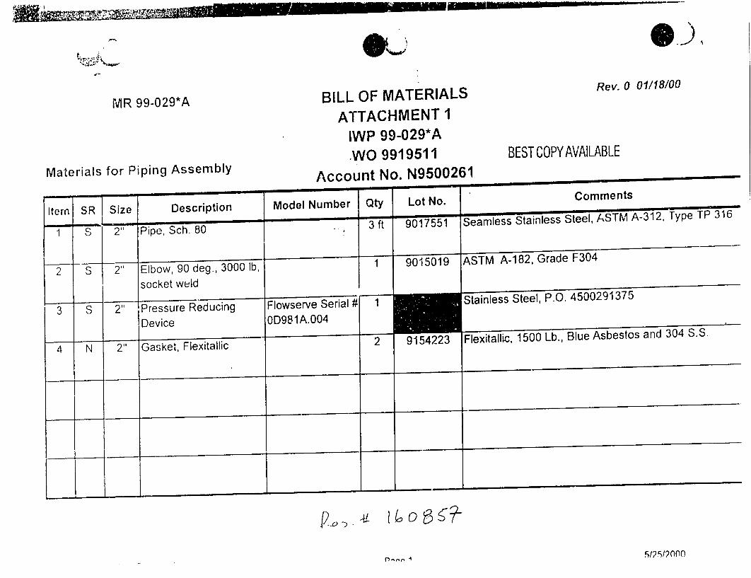
MR 99-029*A
Materials for Piping Assembly
- . - , - r -Size
211
2
2"
2-
Description
Pipe, Sch. 80
Elbow, 90 deg., 3000 Ib,
socket weld
Pressure Reducing Device
Gasket, Flexitallic
Model N
S..-m
Flowserve 0D981A.C
BILL OF MATERIALS [e v.
ATTACHMENT 1
IWP 99-029*A -WO 9919511 BEST COPYAVAILABLE
Account No. N9500261
lumber Qty Lot No. Comments
3 ft 9017551 Seamless Stainless Steel, ASTM A-312, Type TP 316
1 9015019 ASTM A-182, Grade F304
Serial # 1 Stainless Steel, P.O. 4500291375
)04
2 9154223 Flexitallic, 1500 Lb., Blue Asbestos and 304 S.S.
I I
512512000l,-.,n i
Item
1
2
3
SR
S
S S
r, r..g,•' .mB.m m tm• "
I
d•
n^,f n141liRlnn
@-9)"

Wisconsin ULTRASONIC THICKNESS RECORD
Electric P•O.,,ER COUPANY
Component ID: Component Description: Page I of I Sheet No. or W.O. No.:
FE-4050A.B 2" Pipe (two 4.5 Iong sections n/a
down direan of FE-405AIB)
Item No.: NDE Procedure / Rev.: IDR No.:
n/a NDE 104 Rev. 16 n/a
ISO No.: Site / Project: Examiner(s) / Level / Date (Print):
n/a PBNP /n/a Robert Davies /11 /5.31-00
Calibration Block(s) M&TE No. or Couplant / Batch No. / QAR No.: Surface Condition:
SIN: NDECB-009 Ultragel II 96225 n/a As in-service
Search Unit
Calibjit~on %I anufacturer I Model Scrial Nc. Size Frequency ode Ns Cable Tpe I No. Connectorsh
1 Panametrics D798 89820 0.2" 7.5mhz L 2 nia n/a /60"
n/a n/a "hG n.'a n/a n/a n/a
• • Instrument
Manufacturer: Model: N1&TE or S/N
Manfanefirce 36DL Plus iNDEDL-007
26DL Plus or 36DL Plus USN 50 or USN 52
Calibration 1:elc'ct y Screen Wt2 .h Delay DDammp jn l Fre uencv i Pulse Rectfication
2 0.5 nla n/a na n/a n/a
Calibreion Verification Calibration I M Calibration 2
M~stdMeasured
Nominal Thickaess Thickness: Time: 0800 Time: 0830 Nominal Thickness Thickness: Time. n/a Time: n/a
0.101)" 0.100" ac ace n/a n/a n/a n/a
0.260" 0.200" ace ace n/a n/a n/a 11/a
0.300 0.300" arc acc n/a n/a n/a n/a
0.500 1-499 ar, acc n/a n/a n/a n/a
Examination
aSpot Chck Opartial Scan - % Examined 100% Examination
o('hck Elbow Grd Size Thickness
Com onent WL ,d
Diameter Circumference Intradas Extrados Main Do-nstream Toe to Toe Nominal [DR Trieci
Dim tr1/iru frneII Ita o /: , ...... ..
Remarks: Thicknesxes were oad to be roi 0.199" to 0.220" (Scl ed..e 80).
Linitttioit s (It None, so state,,: fl(tlC
I..j'
Exm-e ..... Dt S~~tro .ame e\e Date- (Sigifarre) Reviewer /Level /Date
Form NDE 10
Rcvision 12 9120

PaLe
Nuclear Power Business Unit
RECORD REVIEW - REQUEST FOR COM.IMENTS
Record TvPe: Modification
Record ID: MR 99-029*A (Comments for MR 99-029*B are the same)
Unit: [] 0 0 C1 l 2Record Date: 3-.
CO' IMENTS (INCLUDE SIGNATURE,
Final Desin Description Page 4- The installed piping is
:lass JG-4. The P &ID is incorrect in its identification of the zection as D.E.3. Final Desin Description Pace 5 - NDE requirements
(Or the pipe class in question are not specified in DG
M102. Also, Per NP 7.4.3. the 1990 Edition plus addenda
ot B31.1 is the latest reconciled edition. The state has
approved the 1992 edition. It would appear that a
reconciliation needs to be p,:rformed. i0.59 Screeninm! A. and Safety Eva*uation 2. - RO-0400S ;s identified as RO-04004.
50.59 Safetv Evaluation page 6 - What is the basis for
not requiring a seismic analysis and report?
50.59 Safety Evaluation page 9 - RO-04008 is identified
as IO-04004. Also, an inservice leak test is referred to
on this page, however. the design documentation and
"w\VP identify a hydrostatic test. "
as6ep 27.3- 2.7.3 should be listed before
2.7.2 or 2.7.2 broken into substeps if the roots require
exa mination.
IWP. pae 6- FME inspection before and after welding
should be considered.
IWP. pVae 10, step 3.2.7 - How long should be pipe stub
tic? Should it be cut at the existing butt weld?
MIWP..g,. 10. step 3.2.S - This cou!d be done by CE
QC ý ith a caliper or mic.
P. p~a e 11.se -it the aictual to rque va u
'lbs inste '
sten 3.2.16 - 3.2.16 should be liste
befo;re 3.2.14 or 3.2.14 broken into substeps if the roots
MT. i). , ue 5_!_p 4.4.4 - The minimum flow
Irequirement is listed in IT-!0. What is the basis for the
ifu \mutn flsm requirenwrnt?
Skc,.hi SK%-lR&-99-029*A - Will the weld at AF0027 be
c2iound kut or will a pipe stub bc left? If a pipe stub is
Iclti. . union socket would need tt) be specified on the bill
ol material or a butt W eld perfOrmed. Hlowe\er. there are
n10t union type sockeis listed on the BO, and the sketch
sates that all %velds are to be socket 'A FE4050:\. a
pipe stub is left per the IVP. if the pipe stub is replaced.
it \k ill be a butt weld. Also. will a union type socket
MTION/�&�X?
,~~~r. 64
�x4A-r4�LP�z�.
�A��i.
4;.Aai
ROUTE COMPLA''El) FORMI TO NIM RECORDS MANAGEMlENT
BEST CCPY AVAILABLE Rc!'cr,'kCc NI'131
of 2
V
(
6
I'KI
Record Tv0e: Modification
ye7(- -r'77C----e/
(
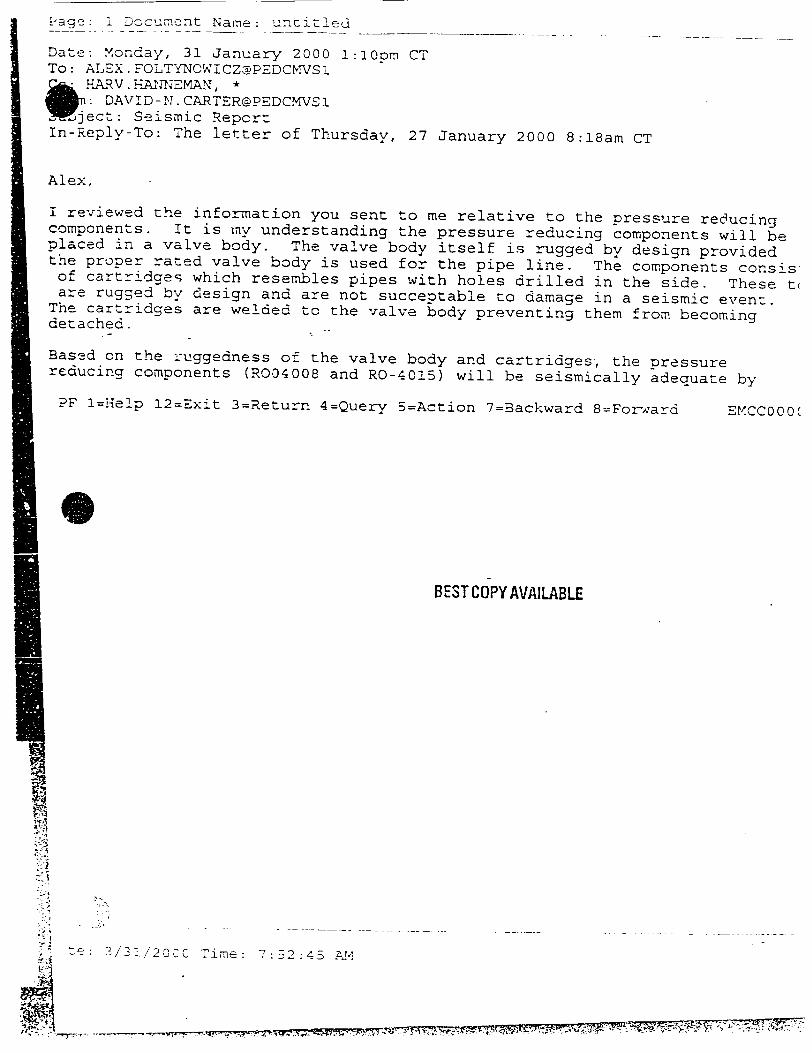
Page: 1 Document Name: unciý1_.6
Date: Monday, 31 January 2000 !:10om CT To: ALEX. F0LTYNOWICZ@PEDCMVS1 Q- HA.RM.HA:'TT;EM'xN, *
: DAVID -N. CARTER@PEDCMVS1 'ject: Seismic Repcrt
In-Reply-To: The letter of Thursday, 27 January 2000 8:18am CT
Alex,
I reviewed the information you sent to me relative to the pressure reducing components. It is my understanding the pressure reducing components will be placed in a valve body. The valve body itself is rugged by design provided the proper rated valve body is used for the pipe line. The components consis of cartridges which resembles pipes with holes drilled in the side. These t( are rugged by design and are not succeptable to damage in a seismic event.
The cartridges are welded to the valve body preventing them from becoming detached.
Based on the ruggedness of the valve body and cartridges, the pressure reducing components (R004008 and RO-4015) will be seismically adequate by
PF !=Help 12=Exit 3=Return 4=Query 5=Action 7=Backward 8=Forward EMCC000(
BEST COPY AVAILABLE
i-P
7
7e: 3/3/20CC Time: 7:72:45AM
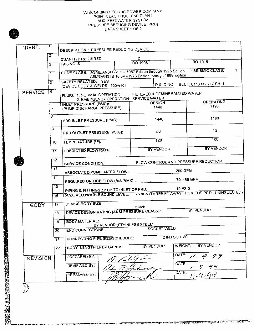
WISCONSIN ELECTRIC POWER COMPANY
POINT BEACH NUCLEAR PLANT
AUX. FEEDWATER SYSTEM
PRESSURE REDUCING DEVICE (PRD)
DATA SHEET 1 OF 2
IDENT. 1 DESCRIPTION.: PRESSURE REDUCING DEVICE
2 QUANTITY REQUIRED: 2
3 TAG NO.'S RO-4008
4 CODE CLASS: ASME/ANSI B31.1 - 1967 Edition through
ASME/ANSI B 16.34 -1973 Edition throuq5 SAFETY RELATED: YES
t (DEVICE BODY & WELDS - 100% R.') P &l
SERVICE 6 FLUID: 1- NORMAL OPERATION:" FILTERED & DEN
2. EMERGENCY OPERATION: SERVICE WATEF
INLET PRESSURE (PSlG): 17ESIGI
(PUMP D;SCHARGE PRESSURE) 1440
18
PRD INLET PRESSURE (PSIG): 144C
9
PRD OUTLET PRESSURE (PSIG): 50
10 TEMPERATURE (0F): 120
11 PREDICTED FLOW RATE: BY VEN[
1 SERVICE CONDITION: FLOW CONTR(
13
ASSOCIATED PUMP RATED FLOW: 14
REQUIRED ORIFICE FLOW (MINIMAX): 15
PIPING & FITTINGS AP UP TO INLET OF PRD:
16 MAX. ALLOWABLE SOUND LEVEL: 75 aBA (THREE
BODY 17 DEVICE BODY SIZE: 2ic 2 inch
18 DEVICE DESIGN RATING (ANSI PRESSURE CLASS):
19 BODY MATERIAL: BY VENDOR (STAINLESS STEEL)
20 END CONNECTIONS: SOCKET
21 CONNECTING PIPE SIZEISCHEDULE.
22 BOrJY LENGTH END-TO-END: BY VENDOF
REVISION PREPARED BY: ./ -,,
REIWE Y
APRVE Y

W.ISCONSIN ELECTRIC POWER COMPANY
POINT BEACH NUCLEAR PLANT AUX, FEEDWATER SYSTEM
PRESSURE REDUCING DEVICE (PRD) DATA SHEET 2 OF 2
ADDITIONAL REQUIREMENTS
1. Pressure reducing device (PRD) assembly shall be designed to withstand seismic loading
equivalent to 3.0 L, in the horizontal direction and 2.0 L, in the vertical direction. When
exposed to the above loading the PRD shall be capable of performing all its functions.
Vendor shall furnish seismic analysis and design report for Purchaser's review.
2. 1hvdrostatic tcsting of the PRD body shall be conductd in accordance with ASME/ANSI
B 16.34 except that the test pressure shall be maintained for at least 30 minutes.
3. All materials in contact with the working fluid shall be austenitic stainless steel.
4. Castings and wvrought nmaterials procured for the manufacture of PRD body and trim
shall be in accordance with applicable ASTM and ASME specifications and Certified
Material Test Reports shall be furnishied.
.All welding shall be in accordance with ASME Section IX requirements.
6. Examination requirements for pressure retaining parts of the PRD shall be in accordance
\\ith ASIME/ANSI B 16.34. Section 8.0. In addition. radiographic examination shall be
performed in accordance with ASME Section V. Article 2.
7. Provide calculation certifying that the design flow comply with Data Sheet 1
requirements. These calculations shall be reviewed and accepted by Wisconsin Electric
Po\\cr Company prior to PRI) fabrication.
8. Fabrication drawing, indicating PRD parts list and their associated ASME /ANSI
standards. .hall be submittcd for Wisconsin Electric Power Company approval prior to
PRD fIabrication.
9. Provide Certificate of Compliance attesting that the PRD is designed in accordance with
P.O. specified requirements.
t0. Provide eight (8, copies of Instruction Nianuals for PRD including Parts List and Part
N tmbers.I

PBNP MINOR PROCEDURE F
Check As Applicable
WORK ORDER WORK PLAN
FOR MODIFICATION # MR 99-029*A1 WO# 99411
INSTALLATION WORK PLAN TITLE
Aux. Feed Water Pump P-38A Minimum Flow Recirc Line Orifice Modification
UNIT 0 [N QA-SCOPE
Originator A. Foltynowicz?
Reviewer R. C an
Final Design Group Head R. Hornak
"-" NON QA-SCOPE
Ii
Installation / Group Head J. Bausch / " i'• Date
iara.cer - / :5,4~s Operations or DSS M. Schue Date_ z- /
NOTE: Changes to this work plan must be done with the concurrence of the
responsible or team engineer and the installation surpevisor, or as delineated within the IWP.
BEST COPY(AVILABLE
48

SIWP NUMBER: 99-029*A1 Page 1 of 16
INSTALLATION WORK PLAN _
PBNP MLNOR PROCEDURE [e
Check As Applicable
WORK ORDER WORK PLAN
FOR MODIFICATION # MR 99-029"Al , WO # 9934148
INSTALLATION WORK PLAIN TITLE
Aux. Feed Water Pump P-38A Minimum Flow Recirc Line Orifice Modification
UNIT 0 ?j QA-SCOPE NON QA-SCOPE
Originator A. Foltynowicz -Date
Reviewer R. Chapman Date
Final DesiEn Group Head R. Hornak Date
Quality Engineer 1. Polacck Date
Installation
Group Head J. Bausch Date
Nlanau~cr Operations or DSS M- Schuie Date 0. 0
NOTE: Changes to this work plan must be done with dC -oncurrence of the
responsibie or team engineer and the installation surpeviqor, or as delineated within the IWP. DG-G02.5
Revision IL

IWP 99-029"*A WORK PLAN FEBRUARY 19, 2001
1.0 SCOPE
1.1 The scope of this installation work plan is to drill additional openings in the pressure
reducing orifice RO-04008 flow assembly cylinder.
1.2 The purpose of this modification is to increase the flow through the pressure reducing
orifice RO-04008.
1.3 The approach of this installation is as follows:
1.3.1 Isolate and drain the affected piping.
1.3.2 Remove and drill RO's flow assembly cylinder (trim).
1.3.3 Re-install RO's flow assembly trim.
1.3.4 Functionally test the mini-recirc. line to verify operability.
1.3.5 Perform leak check of modified RO-04008.
1.4 This installation is QA-scope work.
1.5 Installation of this IWP will be performed during the Reactor being in any operating
condition. The pump P-38A will be out of service under a seven (7) day LCO. No other
AF pump can be out of service.
1.6 This modification will no, affect any ASME Section XI pressure boundaries.
1.7 Support Requirements
1.7.1 Operations: Support to install and remove danger tags, system draining, and
post maintenance and operability testing.
1.7.2 QC: Perform examinations where specified in this IWP.
1.7.3 Engineering: Support QC evaluations and post maintenance testing.
RE: Alex Foltynowicz Pager: 5518 Home Tel. No. 686-0098
Page 2 of 16
NUCLEAR POWER BUSINESS UNIT
INSTALLATION WORK PLAN
AUX FEED WATER PUMP P-38A MINIMUM FLOW
RECIRC LINE ORIFICE UNIT I & 2

NUCLEAR.POWER BUSINESS UNIT
INSTALLATION WORK PLAN
IWP 99-029*A 1 WORK PLAN FEBRUARY 19.2001
AUX FEED WATER PUMP P-33A MINLMNUMI FLOW
RECIRC LiNE ORIFICE UNIT 1 &2
1.7.4 Maintenance:
a. Disassemble RO as required. "
b. Perform RO drilling, as required. -'
c. Assemble RO as required. .- f
2.0 PRE-INSTALLATION REQUIREMENTS
"N
\K2.1 References:
2.1.1 Working drawing:
a. SK-MR-99-029*A, "Auxiliary Feedwater System Orifice RO - 04008
Replacement, Unit 1 & 2.
2.1.2 Vendor/Contractor drawing:
a. Flowserve Corporation drawing of the replacement orifice.
Responsible Engineer has assured that all references listed above are approved and the
applicable requirements have been incorporated into the IWP. The referenccs are either
with the Installation Group, attached, or are readily available to the Installation Group.
RE __ __
2.1.3 Applicable Codes and Standards:
Date .3-/ ý/- /
a. USAS B31.1 - 1967
b. ASMEB31.1 - 1992
Supplemental Procedures:
a. M1 32.1
b. MI 32.8
c. NP 1.9.6
d. NP 1.9.15
D,•,,•F--TO •{!'' '': '-
Flange and Closure Bolting
Guidelines for Opening Piping Systems
Plant Cleanliness, Storage, and Inspection Program
Danger Tzta Procedure
Pa c 'c 3 of 16
2.1.4
IWP 99-029"A 1 WORK PLAN
FEBRUARY 19, 2001
AU'X FEED WATER PUMP P-38A MINIMUM FLOW
RECIRC LINE ORIFICE UNIT 1 & 2
e. NP 8.4.10
f. NP 8.5.2
g. PBF-9142
h. WP-7
Exclusion of Foreggn Material from Plant Components and Systems
CHAMPS Equipmeiit Database Usage and Control
Bolting-Torque And Loading
Welding Procedure for Stainless Steels Group P-8 GTAW-Pipe Diameters over 1" OD
2.2 Background References (those references not needed to perform work):
2.2.1 Drawings:
a. Bechtel Drawing M-217, Sh. 1, P&ID of Auxiliary Feedwater System
2.3 Installation Preparation Activities
2.3.1 A Bill of Material (BOM) is attached to this IWP or is included on the
Working Drawing.
2.3.2 The Responsible Engineer has assured that all materials on the BOM are on
site, available for the modification, and QA released.
The RE/IS has assured that all of the above Installation Preparation Activities
are complete.
REIS Date
2.4 Pre-Installation Discussions
2.4.1 A pre-installation diszussion with the Installation Group representative, the
Testing Group representative, and the Acceptance Group representative has
been performed.
RE/IS ______Date J> c-
Page 4 of 16
NUCLEAR POWER BUSINESS UNIT
INSTALLATION WORK PLAN

Page 5 of 16
NUCLEAR POWER BUSINESS UNIT IWP 99-029*Al
INSTALLATION WORK PLAN WORK PLAN FEBRUARY 19,2001
AUX FEED WATER PUMP P-38A MINIMUM FLOW
RECIRC LINE ORIFICE UNIT I & 2
2.4.2 A field walkdown has been performed, if necessary, to verify that all aspects
of the proceduie may be performed as intended.
IS _____ _Date Y" 0
2.4.3 Foreign material exclusion (FME) shall be cortrolled per NP 8.4.10,
Exclusion of Foreign Material from Plant Components and Systems, and
PBF-9158, FME Checklist.
REIS 0 Q -, Date __-___ -U
2.5 Personnel Safety Concerns
The following precautionary personnel safety requirements are recommended for this
IWP:
2.5.1 Caution should be exercised when lifting or rigging components.
2.5.2 This installation will take place in an area of increased fire awareness.
Installation personnel shall take precautions against fire hazards.
2.5.3 Aux. Feedwater pump P-38A minimum recirculation line does not have drain
connections. To allow this line to drain, metering orifice's (FE-04050A)
downstream flange will be broken open. Safety caution of MI 32.8, Guideline!
for Opening Piping Systems shall be utilized. A "Catch Drain" arrangement
shall be established to catch or funnel liquid to drain to prevent dripping to th(
floor.
The Installation Supervisor is satisfied with Fire and Drainage arrangement.
is Date .
2.6 Identification of Permits Required
2.6.1 Work Order # 9934148 for this IWP has been written and submitted to
CHAMPS. The Work Order number has been recorded on the IWP
coversheet.

NUCLEAR POWER BUSDNESS UNIT
INSTALLATION WORK PLAN
IVP 99-029*A 1 WORK PLAN FEBRUARY 19,2001
AUX FEED WATER PUMP P-38A MINIMUM FLOW RECIRC L-INE ORIFICE UNIT 1& 2
The Installation Supervisor has assured that all necessary permits for this installation will be obtained.
Is 7 Date 3 - /1{-0 (
2.7 Pre-Installation Work
N/A
2.8 Operational Installation Prerequisites
This installation may be performed with Unit 1 and Unit 2 being in any operating condition that does not require AF pumps.
Establish twice per shift fire rounds per OM.3.27, Protection of Safe Shutdown/Appendix R Equipment.
Enter applicable LCO for P-38A, AF system pump being OutOf-Service.
Prepare a Danger Tag Series to isolate RO-04008. DO NOT HANG the tags until instructed to do so in Section 3.0.
Release For Installation
All of the above operational installation prerequisites have been met and is acceptable to proceed with the installation.
rSS /.1-//h' q Date Time "
All other installation prerequisites have been met including performance of a pre-job brief with all involved personnel, as required.
RE/IS ( a~aS /,5
OPS'Date
OPS/Daite
Date - - / _ - 6'1/
Page 6 of 16
2.8.1
2.8.2
2.8.3
2.8.4
2.8.5
2.8.6

NUCLEAR POWER BUSINESS UNIT INSTALLATION WORK PLAN
IWP 99-029*A1 WORK PLAN FEBRUARY 19. 2001
AUX FEED WATER PUMP P-38A MINIMUM FLOW RECIRýC LINE ORIFICE UNIT 1 &2
3.0 MODIFICATION
3.1 QC Requirements
Hold, inspect, or witness points are included, as needed, in the body of the installation description.
3.2 Installation Description
NOTE: The ;ollowing ;s a detailed step-by-step listing of the actions necessary to perform this IWP. The steps are to be performed in a logical work order. Work can be performed in an order othcr than as written at the discretion of the Responsible Enrineer or the Installation Supervisor.
3.2.1 Hang the Danger Tag Series prepared in Step 2.8.4.
3.2.2 Provide temporary supporting as necessary. N'.o fec'Frer..oir oo+/ txJ
3.2.3 Drain and vent Line 2"-DB-3 by breaking the flange at orifice FE-04050A. Control drainage as well as possible by using hoses, and catch basins. Coordinate with Operations as necessary.
Page 7 of 16
CAUTION Aux. Feed. pump P-38A minimum recirculation line does not have
a drain connections. To allow system to drain, downstream flange of
metering orifice FE- 04050A shall be broken open. Safety caution of NI 32.8, Guidelines for Opening Piping Systems shall be observed.
OPSIDate
TN/Date

NUCLEAR POWER BUSINESS UNIT INSTALLATION WORK PLAN
IWP 99-029*A I WORK PLAN FEBRUARY 19, 2001
AUX FEED WATER PUMP P-38A MINIMUM FLOW RECIIRC LINE ORIFICE UNIT 1 &2
NOTE:
3.2.4
3.2.5
3.2.6
3.2.7
3.2.8
3.2.9
3ketch No. 2, attached shall be utilized for identiflication of tLe ieferenced parts number.
N/Date
Remove the bonnet cap (blind flange) (70) from the device (1). Protect the gasket surface from damage.
Remove the bonnet cap gasket (58) and discard.
Remove the seat retainer (30) and place in a safe location.
Remove the seat ring (20) and place it in a safe location protecting the gasket surface from damage.
Remove the seat ring gasket (55) and discard.
Page 8 of 16
CAUTION
If leakage past isolation valve AF-27 is seen, STOP work and contact the IS or RE immediately.
CAUTION
Take extreme care to apply all possible fire protection precautions in the AF pump P-38A cubical.
Remove the nuts (114) from the studs (108).
TIN/Dat'e

iN UL~Lj2AK kUWL_.K UUN.55 UiNII
INSTALLATION WORK PLAN
AUX FEED WATER PUMP P-38A MINILMUM FLOW RECIRC LINE ORIFICE UNIT 1 & 2
IWP 99-029*A1 WORK PLAN FEBRUARY 19, 2001
3.2.10 Grind off the tack weld holding the alignment pin in place in the seat retainer (30) and remove the alignment pins (258). Save the alignment pins for re-use if they not damaged.
3.2.11 Remove the innermost (6&) stage (30F) of the seat retainer (30).
3.2.12 Drill six (6) additional 0.076+i- 0.002 (#48) holes as shown on the attached marked up Sketch No. 1 of the innermost (6th) stage (258) of the seat retainer (30) and remqn burr,
ICd~1~ 6 4
NOTE: Alignment marks are located at the top of the seat retainer (30).
3.2.13 Install the alignment pins (258) and tack-weld them in place with a 1/8" tack-weld on the edge of the outer hole in the seat retainer (30). The tack-weld to be welded per WP-2 welding procedure. Filler ru-aterial to be ER316.
BEST COPY AVAILABLE
FME HOLD Point
3.2.14 Prior to RO's trim installation, perform FME cleanjiness inspection of RO-04008 body. QC to utilize fiberscope to perform FME inspection. Document results on attached PBF9158.
3.2.15 Install a new seat ring gasket (55) in the body (1).
3.2.16 Install the seat ring (20) in the body (1).
Page 9 or 16
QC/Date
N 10 Iat
AAm
(T/Date
(NITN/15ate,
, --- /It
3 N/Date'
-772ýli "7777 777 iv
h
I He,. 1,

NUCLEAR POWER BUS[NESS UNIT
INSTALLATION WORK PLAN
IWNP 99-029*A1 WORK PLAN FEBRUARY 19, 2001
AUX FEED WATER PUMP P-38A MINIMUM FLOW
RECIRC LINE ORIFICE UNIT 1 &2
3.2.17 Install the re-assembled seat retainer (30) in the body (1) being
3.2.17 Install the re-assembled seat retainer (30) in the body (1) being careful to ,:enter it on the seat ring (20).
3.2.18 Install a new bonnet cap gasket (58) in the body.
CV)!)-dit
312do
Place the bonnet cap (70) on the body (1).
Reinstall the nuts (114) on the studs (108). See QC hold point below.
N/Date
OC HOLD Point
3.2.21 Torque bolts using a staggered pattern. Torque the bolts to 130
Ft-Lbs (+/-) 6 Ft-Lbs in accordance with PBF-9142.
QC SHALL witness final torquing of bolts.
M&TE: 'iJTW,) -0-7(,f
Cal. Due Date: __ ___'-_ _
Final "As Left" torque value: / 1-2
3.2.22 Install the FE-04050A orifice flange and gasket. See QC hold point below. -)-I
2C HOLD Point
BEST COPY AVAIL.BLE
/
'MTNIDate
3.2.23 Torque bolts using a staggered pattern. Torque the bolts to 255 Ft-Lbs (+/-) 12 Ft-Lbs in accordance with PBF-9142.
QC SHALL witness final torquing of bolts.
M&TE:
Cal. Due Date:
Final "As Left- torque value:
I7 i 1"L- / 7 /( C/Date
(, T/Dd-te"
tQ--/ / f-#, I
5
ril age ki~l

NUCLEAR POWER BUSINESS UNIT INST,,LLATION WORK PL-AN
AUX FEED WATER PUMP P-38A MINIMUM FLOW RECIRC LINE ORIFICE UNIT 1 &2
IWP 99-029*AI WORK PLAN FEBRUARY 19, 2001
3.2.24 Remove temporary supports.
3.2.25 Restore f-re protection for AF system pump room as necessary and notify Maintenance to release fire watch.
3.3 Clean upt
Remove all constructin debris, tools, and material from the work area. Ensure all work areas meet PBNP housekeeping expectation.
Is (I,,J') (-
CE/Date
OPS/Da•/
Date .3 -/•(-
3.4 Installation Complete
3.4.1 As-Buil Description
This PP was installed by:- ./ L ; 6" Date -3 -1 Y-0 I
The installation was performed in accordance with this IWP and drawings (list revisions):
ECR.(s) No. AJ/A CR(s) No. A,/A Othzr considerations /t-.
,-%ttach any additional documentation of the as-built description to this FVP.
List all calibrated equipment used during installation of this modification. ,-I (_i- ' - 0 7q [4 , -/0; i
BEST COP'( AVAI LAB LE
Page 1 I of L6
-,--
3.4.2

IWP 99-029*A 1 WORK PLAN FEBRUARY 19, 2001
AUX FEED WATER PUMP P-33A MLNIMUM FLOW RECIIRC LINE ORIFICE UNIT 1& 2
3.4.3 The installation of this IWP is complete. It has been installed in accordance with this IWP and all associated ECRs.
RE <ý: Z-/ Date/ IS !" - Date 3 - / 9'-0 (
4.0 TESTING
4.1 Testing Information
4.1.1 The acceptance tests for this modification are:
a. Initial service leak check performed at normal operating pressure and temperature.
b. Functional Test of modified orifice RO-04008 performed during the IT-10, "Test of Electrically-Driven Auxiliary Feed Pumps And Valves " or 10-62A, "Motor-Driven Auxiliary Feedwater System (P-38A & P-38B).
4.1.2 The intent of the testing is to:
4.1.3
BEST COPY AVAILABLE
a. Verify the functional performance of modified orifice.
b. Verify the integrity of the modified orifice.
Acceptance criteria for the testing is as follows.
a. Modified RO-04008 shall not show any evidence of through-flange leakage at normal system opciating temperature and pressure.
c. Flow reading on FIT-4050A or UT flowmeters must be between 70 and 100 gpm.
4.2 Pre-Test Requirements
Remove the Danger Tags h½ut were hung in Step 3.2. 1.
Prepare pump P-38A for the rc-:tart. Fill and vent pump.
Pa2e I2ot 10
4.2.1
4.2.2
_)PS/Dat
NUCLEAR POWER BUSINESS UNIT INSTALLATION WORK PLAN

NUCLEAR POWER BUSINESS UNIT IWP 99-029"A1 INSTALLATION WORK PLAN WORK PLAN
FEaRUARY 19, 2001
AUX FEED WATER PUMP P-38A MLNIMUM FLOW RECIRC LINE ORIFICE UNIT 1 &2
4.3 Release for Testing
4.3.1 The Aux Feed System's pump P-38A operating mode is as required for testing. Testing can start.
DSS • 4 1•I•PJ Datefl4MAP-6 Time 23ý>
4.4 Testing,
RO-04008 Performance Test.
4.4.1 Align AF system as necessary and perform pump P-38A recirc. line flow performance test utilizing IT-10, "Test of ElectricallyDriven Auxiliary Feed Pumps And Valves " or OI-62A, "Motor-Driven Auxiliary Feedwater System (P-38A & P-38B) procedures. Record a flow reading from FIT-04050A while valve AF-04007 is open.
4.4.2 Verify the flow reading by utilizing two (2) additional ultrasonic flow meters. Flow Reading (FIT-04050A) 1 71C gpm.
Flow Reading (UT Flowmeter 1) 1L I gpn.
M&TE: CC-. tA-•0 -O ,
Cal. Due Date: (_•Q- 2-( C
Flow Reading (UT Flowmeter 2) 7-3 gpm.
M&TE: F- E -H A)
Cal. Due Date: _/ -___ _ _
' ENG/Date
Acceptance ciiteria: The flow reading must be between 70 and 100 gpm.
BEST COPY AVMiLABLE
Pagc 13 of 16

NUCLEAR POWER BUSINESS UNIT INSTIALLATION WORK PLAN
PVP 99-029*A I WORK PLAN FEBRUARY 19, 2001
AUX FEED WATER PUMP P-38A MINLvIUM FLOW RECIRC LINE ORIFICE UNIT 1 &2
Initial Service Leak Check.
CAUTION Use caution when examining piping and welds. The
system operating pressure may be in excess of 1300 psig.
4.4.3 Perform a initial service leak check of the modified RO-04008 while the pump P-38A is running during IT-10 or OI-62A. Examine for leakage and record results below.
OPS/Date
Acceptance criteria: No visual evidence of weeping or leaking at a new joint.
4.5 Testing Results
4.5.1
4.5.2
4.5.3
Attach any additional testing documentation to this IWP.
List all calibrated equipment used during testing of this modification. C.E r "'4 - CC"2
The testing is completed and all Acceptance Criteria have been met.
Testing Supervisor t2?. &
Pag-e 11 of 16
DateD3I0

NUCLEAR POWER BUSINESS UNIT INSTALLATION WORK PLAN
IWP 99-029"A I WORK PLAN FEBRUARY 19, 2001
AUX FEED WATER PUMP P-38A MINIMUM FLOW
RECIRC LINE ORIFICE UNIT 1 &2
5.0 RESTORATION
5.1 Pre-Acceptance
5.1.1 The following items must be completed prior to acceptance:
a. All ECRs have final approvals.
b. All update items required prior to acceptance on PBF-1606 have been completed.
c. All testing described above has been satisfactorily completed.
All of the above items have been completed.
RE Date____ ____Dat
5.2 System Restoration
5.2.1
5.2.2
5.2.3
Close out any remaining tagouts and permits for this IWP.
Aux Feedwater pump P-38A is ready for release for operation.
Exit LCO on AF pump P-38A. x- 4-5 m s
D ~sI~i~ Date 3J S4 't TiineLIn? S(
6.0 ACCEPTANCE
6.1 Verify systems and components affected by this modification are placed in an appropriate condition for present plant configuration.
6.2 If fire rounds in progress, then discontinue fire rounds.
Page 15 of 16
OPS/Date
OPS/Date
NUCLEAR.POWER BUSINESS UNIT
INSTALLATION WORK PLAN
IWP 99-029*A I WORK PLAN FEBRUARY 19, 2001
AUX FEED WATER PUMP P-38A MINIMUM FLOW RECIRC LINE ORIFICE UNIT I &2
6.3 Final Acceptance
This installation and the associated modification have been installed and tested and are acceptable. I
IW � Date _ _
A
Page 16of 16
Return completed IWP and modification to Responsible Engineer

MR 99-029*A1 BILL OF MATERIALS ATTACHMENT 1 IWP 99-029*A1 WO 9934148
A,-,-,%,,nt 1JE9., MQgNflfl21Materials for Modification
Item SR I Size Description Model Number oty Lot No. Commonts
1 N RO's Bonnot Cap Gasket 2 Fiowserve Dwg. 94-16219 Rev. A. Part No. 58. Ordered under P.R.No. 10135172
N RO'i Soat fllng Gasket 2 Flowserve Dwg. 04-16219 Rev. A, Part No. 65. Ordered under P.R.No. 10135172
3 N 2' Flange Gasket, Flexitalic 2 9154223 Flexitalic, 1500 Lb., Blue Asbestos and 304 S.S.
4 S Seat Retainer, 6th stage 1 Flowsrve Dwg. 94-16210 Rev. A, Part No. 30F. Ordered under P.R.No. 10135172
cylinder
5 S Alignment Pin 2/sets Flowserve Dwg. 94-16219 Rev. A, Part No.258. Ordered under P.R.,o. 10135172
Rev. 0 02)2 /VI

Y"UCLEAR POWER BUSINESS UNIT FIRE PROTECTION CONFORMANCE CHECKLIST
MR 99-029"A
AF
Unit I Unit 2
Location
Common Facilities
Control Bldg. El. 8 It.
AFFECTED FIRE ZONE(S) (see FPER Sect 5.3 - 5.5) 304
PURPOSE
The Fire Protection Conformance Checklist (FPCC) was developed to help evaluate the impact of plant modifications, procedura changes, and tests on the plant fire protection program and safe shutdown capability for compliance with 10 CFR 50 Appendix R and other plant fire protection license commitments.
The FPCC also provides the screening criteria to ensure that a 10 CFR 50.59 safety evaluation is performed on activities that affect the design basis of fire protection equipment or plant's capability to achieve and maintain safe shutdown for any design basis fire. If the FPCC screening indicates the plant fire protection or safe shutdown design basis will be affected, a 10 CFR 50.59 screening shall be performed per NP 10.3.1. Authorization of Changes, Tests, and Experiments (10 CFR 50.59) with consideration of the FPCC information, to determine if an unreviewed safety question is involved. The design basis fire is the accident to be considered in the 10 CFR 50.59 evaluation. The FPCC becomes part of the documentation supporting the 10 CFR 50.59 screening and safety evaluation.
INSTRUCTIONS
I. Complete the Fie Protection Conformance Checklist (FPCC) as directed in paragraph 8.4.3 of the FPER.
2. Determine whether the modification affects general plant industrial or Appendix R fire protection features by completint Sections 1.0 - 4.6 of the FPCC.
Use the paragraphs in FPER 8.4.3.1 that correspond to the FPCC sections for additional information and guidance when answering the questions in the checklist.
3. Determine whether the modification affects Appendix R safe shutdown systems or components by completing Sections 5.0 - 10.5 of the FPCC.
Use the paragraphs in FPER 8.4.3.2 - 8.4.3.7 that correspond to the FPCC sections for additional information and guidance when answering the questions in these sections of the checklist.
4. Consider requirements for a 10 CI'K )0.59 screzning by reviewing paragraph 11.0.
5. Sign and date the FPCC.
1'1~ -2 ,'I
i~ i •u 2 '-'p:•;': P,•c 1':.2
M1R Number
S) stem
X

FIRE PROTECTION CONFORMANCE CHECKLIST
FIRE PROTECTION EVALUATION
1.0 I'LANT ACCESS (Ref. FPER 8.4.3. 1.1)
1.1 Does the modification add'delete.'revise any doors, walls, structures or equipment that may impede or alter
access to a fire?
"- Yes, go to 1.2
[ No, go to 1.3
Comments:
1.2 Are alternate access routes available to the area of concern?
D- Yes, go to 1.3 D No, go to 1.8, complete actions wid resume at 1.3
Comments:
1.3 Does the modification add'revise/remove ventilation that may either directly or indirectly alzer air flow within
an area or from zrea to area to impede access to a fire?
- Yes, go to 1.8, complete actions and resume at 1.4
Z No. go to 1.4
Comments:
1.4 Does the modification require installation of Io,: ; r. r;-' y unlocked doors or structural changes such as
the additionrdeletion 'revision of walls, stairways, or doors?
D Yes. go to 1.5
[7 No, go to 1.6
Comments:
1.5 Does the installation of lucals or structural changes affect the existin2 access/cgress routes for fire figh'ing
activity, safe shutdown equipment operution! and/or post-fire repairs?
nl Yes, go to I.S. ccmplcte actions and restime at 1.6
--] No, go to 1.6
Comments:
RlB ;*-2(-.2 Rc',i-;icr 2 0)7.,(129X',
0
[1 "n., 2 0 1*25

FIRE PROTECTION CONFORM.ANCE CHECKLIST
1.6 Does the modification atfect the Appendix R safe shutdown timeelines (time and motion study for AOP I0A, AOP 10B. AOP IOC, or AOP IOD contained in FPER Sections 6.8 and 6.9, Figs. 6.8-3 and 6.9-3)'.
-- Yes, go to 1.8, complete actions and resume at 1.7
[• No, go to 1.7
Comments:
1.7 Does the modification block safe shutdown equipment or a local control station required to be accessible for
safe shutdown? (Ref. FPER Tables 6.7-1 to 6.7-4)
- Yes, go to 1.8. complete actions and resume at 2.1
i No, go to 2.1
Comments:
1.8 The modification affects plant accessibility. List the access effect(s) and refer to FPER, Section 8.4.4, RESUME checklist completion.
Access Effects:
APPENDIX R BARRIERS (Ref FPER 8.4.3.1.2)
2.1 Does the modification delete any fire barriers/area appearing in FPER, Section 5.3 - 5.5? of Vol. 2 FPER,
Drwvgs. PBC 218, Shts. 1- 19)
F-1 Yes, go to 2.2
Z No, go to 2.3
Comments:
2.2 Has a new barrier/area been defined?
DYes, go to2.3 DNo, go to 2.14. complete actions and resume at 2.3
Comments:
Ftc� �''n 2 (7 -� �)!
. 2.0
I -,z 3 t , 25

FIRE PROTECTION CONFORMANCE CHECKLIST
2.3 Does the modification revise any cxisting fire barriers (e.g.. changes to supporting structural stcel barrier
thickness or mater ial etc.)?
D-' Yes, go to 2.14, complete actions and resune at 2.4
[ No, go to 2.4
Comments:
2.4 Does the modification add/delete/revise any penetrations to fire barriers due to cables or pipes?
D- Yes, go to 2.5
Z No, go to 2.6
Comments:
2.5 Are the appropriate barrier penetration procedures specified? (NP 8.4.11)
r-- Yes, go to 2.6
D No, go to 2.14, complete actions and resume at 2.6
Comments:
2.6 Does the modification add or replace any fire doors, frames or dampers?
D Yes, go to 2.7
[ No, go to 2.8
Comments:
2.7 Do the new/replaced dampers/doors/frames meet requirements for rated fire barriers in the fire zone and fire
damper installation configurations as specified in FPER Section 5.6? (In FPER Vol. 2 Fire Hazard Evaluations)
P. Yes, go to 2.8
D] No, go to 2.15. complete actions and resume at 2.8
Comments:
".:-z
FF;t �'i6I)
P J-c 4 0t _,:

2.8 Dots the modification add or relocate any cable raceways to a location which presents intervening combustibles between redundant safe shutdown trains? (Review Exemption Requests - Bases for Fire Zone in FPER Vol. 2-3)
D- Yes, go to 2.9
I No, go to 2.10
Comments:
2.9 Does the modification include installation of approved fire stops?
"' Yes, goto2.I0 -"'No, go to 2.5, complete actions and resume at 2.10
Comments:
2.10 Does the modification add/delete/revise any cable to an existing. rac.!way which presents intervening combustibles between redundant safe shutdown trains?
n Yes, go to 2.11
Z No, go to 2.12
Comments:
2.11 Does the modification include installation/reinstallatign of approved fire stops?
I Yes, go to 2.12
'"'1 No, go to 2.15, complete actions and resume at 2.12
Comments:
2.12 Does the modification add/delete/revise any curb, dikes, or drains in the area as described in FPER Vol. I, Section 4.1.12, 8.32.1.3 and Specific Fir-, Zone(s) Fire Hazard Evaluation(s) in FPER Vo!s. 2 and 3, Section 5.6?
[] Yes, go to 2.14, complete actions and resume at 2.13
1N No, go to 2.13
Comments:
)I'11F-2060 Rc% ision .' 07/(2I?99 Pa'e 5 of 2
FIRE PROTECTION CONFORMANCE CHECKLIST

FIRE PROTECTION CONFORMANCE CHECKLIST
2.13 Does the modification obstn'ct, removerevise any suppression sstem or water spray nozzles or plume impingement shields in the area?
[] Yes, go to 2.J4. complete actions and resume at 3.1
17 No, go to 3.1
Comments:
2.14 Do the affected barriers/fire areas protect safe shutdown components or cables?
[-1Yes, go to 2.15
" No, go to 2.16
Comments:
2.15 The modificatior impacts Aprvndix R compliance. .ist the affected items and refer to FPER, Section 8.4.4. 1. RESUME checklist completion.
Affected Items:
2.16 The modification could impact fire protection commitments and.or codes. List the affected item and refer to
FPEP. Section 8.4.4.2. RESUME checklist completion.
Affected Items:
3.0 FIRE PROTECTION SYSTEMS (Ref. FPER 8.4.3.1.3)
3.1 Does the modification affect any portion of the fire protection system?
] Yes, go to 3.2
SNo, go to 3.4
Comments:
3 2 Is the affected poition of fire protection system required for Appendix R safe shutdown compliance? (See
Exemption Request or Rcgulatory commitment Sections of Specific Fire Zone(s) Fire Evaluation(s) in FPER
Vols. 2 and 3, Section 5.6)
D Yes. ,,o to 3.3
L- No. go to 3.4
Comments:
jy
Rc'i.isn 2 07Jfl,96 P'aue 6 of 25

FIRE PROTECTIC'N k..,' FORN1ANCE CHECKLIST
33 Will the modified portion of fire pro'-.'c:.,.)n systems meet the requirements of Appendix R as stated in the Fire Zone Evaluation,• Vols. 2 and 3, FPER Section 5.6?
D] Yes, go to3 4 -] No. to go 3. 18. complete actions and resume at 3.4
Cc mments:
3.4 Does the modification add'delete/revise any fire protection system electrical components?
D- Yes, go to 3.5
Z No. go to 3.6
Comments:
3.5 Does the modification add'deletefrevise anything that could impede the required fire protection system function?
i' Yes, go to 3.17. complete actions and resume at 3.6
-] No, go to 3.6
Comments:
3.6 Does the modification add'delete/revise any fire detectors?
D-I Yes, go to 3.17, complete actions and resume at 3.7 H No, go to 3.7
Comments:
3.7 Does the modification revise any ventilation system flow patterns or structural arrangements which may affect fire de:ection'suppression capability?
P Yes, go to 3.1.7, complete actions and resume at 3.8
Z No, go to 3.8
Comments:
PI:-o 2 0e(V I) R..,, sitn 2 O7,02/I)• Il'aj'c 7 o "
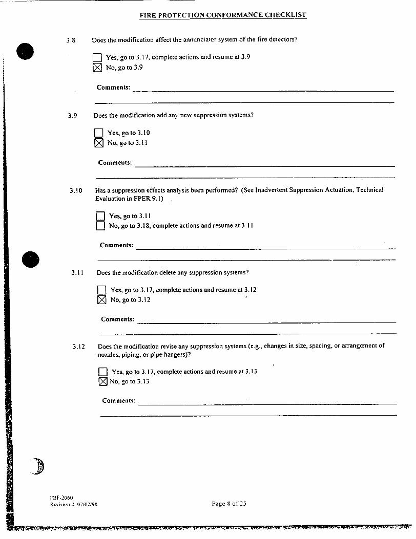
3.8 Does the modification affect the annunciator system of the fire detectors?
E-i Yes, go to 3.17, complete actions and resume at 3.9
!L No, go to 3.9
Comments:
3)PBF-2060 Re% ision 2 07'0-1P98
E PROTECTION CONFORMANCE CHECKLIST
ONT;tw"
3.9 Does the modification add any new suppression systems?
--] Yes, go to 3.10 [7 No, go to 3.11
Comments:
3.10 Has a suppression effects analysis been performed? (See Inadvertent Suppression Actuation, Technical
Evaluation in FPER 9. 1)
- Yes, go to 3.11
L-- No, go to 3.18, complete actions and resume at 3.11
Comments:
3.1 I Does the modification delete any suppression systems?
-] Yes, go to 3.17, complete actions and resume at 3.12
[ No, go to 3.12
Comments:
3.12 Does the modification revise any suppression systems (e.g., changes in size, spacing, or arrangement of
nozzles, piping, or pipe hangers)?
r-- Yes, go to 3.17, complete actions and resume at 3.13
[ No, go to 3.13
Comments:
Page 8 of"25

FIRE PROTECTION CONFORMANCE CHECKLIST
3.13 Does the modification affect discharge characteristics of gaseous systems due to changes in room volume or ventilation systems?
R Yes, go to 3.17. complete actions and resume at 3.14
[• No, go to 3.14
Comments:
3.14 Does the design change affect the discharge of sprinklers due to structuralmechanical changes?
:j Yes, go to 3.17, complete actions and resume at 3.15
[ No, go to 3.15
Comments:
3.15 Does the modification remove!revise any hose.stations, hydrants, or fire extinguishers?
E] Yes, go to 3.17, complete actions and resume at 3. 16
[ No, go to 3.16
Comments: I 3.16 Does the design change add'delctc/revise any local or remote alarm actuation systems?
R Yes, gn to 3.17, complete actions and resume at 4. 1
fý7 No, go to4.1
Comments:
3.17 Are the affected detectionr/suppression actuation system components located in a fire area/zone for Appendix R
compliance?
D-' Yes, go to 3.18
D] No, go to 3.19
Comments:
3.18 The modification impacts on Appendix R compliance. List the affected componenms and refer to FPER
Section 8.4.4.1. RESUME checklist coiipletion.
Comnments:
Ii1 Fr-2'60 Rcvisin 2 07,'02;98 ['age 9 Of 25

FIRE PROTECTION CONFORMANCE CHECKLIST
3. 19 The modification could impact fire protection commitments and'or codes. List the affected components and
refer to HPER, Section 8.4.4.2. RESUME checklist completion.
Comments:
4.0 COMBUSTIBLE LOADING/FIRE HA7ARF) (Ref FPER 8.4.3.1.4)
4.1 Does the modification increase combustible loading or fire hazard due to new cable installed in cable trays?
R Yes, go to 4.4, complete actions and resume at 4.2
[7 No, go to 4.2
Comments:
4.2 Does the modification increase combustible loading or fire hazard due to lubricating oil or grease?
--1 Yes, go to 4.4, complete actions and resume at 4.3
[7 No, go to 4.3
Comments:
4.3 Does the modification increase the combustible loading or fire hazard due to the addition of ordinary cnmbustibles or combustible liquids?
-] Yes, go to 4.4
Z No, fire protection checklist complete. Continue with Appendix R Safe Shutdown Evaluation at
Item 5.1
Comments:
4.4 Does the increase affect the established level of fire hazard for the given fire area stated in the fire zone
evaiuation contained in Vol. 2 and 3 of FPER Section 5.6? NOTE: Contact NES Fire Protection Engineer if input is needed.
-I Yes, go to 4.6, complete actions and resume at 4.5
I No, uo to 4.5
Comments:
Pa-'' W0 oot251cisIon 2 07,'(21"9N'
711 -7-Ir'T ý'' -

0
APPENDIX R SAFE SHUTDOWN EVALUATION
5.0 SAFE SHUTDOWN COMPONENTS (Ref. FPER 8.4.3.2.2 and 8.4.3.2.3)
5.1 Does the modification require addition of a safe shutdown component? Is tile component located within the Appendix R flowpath boundaries shown in Figs. 6.6-1 to 6.6-81-1 and Figs. 6.9-1 to 6.9-2.d in FPER Vol. 4, Section 6.0.
r- Yes, go to 5.2
[ No, go to 5.5
Comments:
5.2 Will the nvew component support other safe shutdown systems or component(s)? (Refer to Safe Shutdown Components Tables 6.7-1 to 6.7-4 in FPER Vol. 4, Section 6.7)
D] Yes, go to 5.3
I- No, go to 5.4
Comments:
5.3 Are the safe shutdown system(s) or component(s) which the new component will be supporting required to operate for a fire in the fire area in \shicl, the new component will be located?
" Yes, go to 5. 18, complete actions and resume at 5.4
D No. go to 5.4
Comments:
0) -27 0I'
4.5 Does the increase exceed the existing fire control design capabilities of fire protection features for the given fir area? NOTE: Contact NES Fire Protection Engineer if input is needed.
L] Yes, go to 4.6, complete ac,;ons. Continue with Appendix R Safe Shutdown Evaluation at Item 5.1
D] No. fire protection checklist complete Continue with Appendix R Safe Shutdown Evaluation at Item 5.1
Comments:
4.6 The modification impa.ts fire protection compliance. List the fire area and refer to FPER Section 8.4.4. RESUME checklist completion.
Fire Area:
FIRE PROTECTION CONFORMANCE CHECKLIST
P2,-.- ! I U!"-`

FIRE PROTECTION CONFORMANCE CHECKLIST
5.4 Is a redundant component located either outside of the fire area or provided with Appendix R, Section III.G.2 separation? (See Section 6.1 .1.2 for separation criteria)
F-1 Yes, go to 5.5
ED No, go to 5.18. complete actions and resume at 5.5
Comments:
5.5 Does the modification require deletion of a safe shutdown componert? (Ref. Tables 6.7-1 to 6.7-4, CHAMPS Appendix R Code or Figures 6.6-1 through 6.6-8H and Figures 6.9-1 to 6.9-2.d)
F Yes. go to 5.6 [ No, go to 5.7
Coniments:
5.6 Does a safe shutdown component exist that will perform the same function for which the component under consideration was required by AOF 10A, AOP 1OB, AOP IOC, or AOP IOD? (Ref. FPER 6.8 and 6.9 descriptions of shutdo-,%n procedures)
F-] Yes, go to 5.7
FD No, go to 5.18, complete actions and resume at 5.7
Comments:
5.7 Does the modification require revision of a safe shutdown component? (Ref. Tables 6.7-I to 6.7-4, CHAMPS Appendix R Code or Figures 6.6-1 through 6.6-8H and Figures 6.9-1 to 6.9-2.d)
71 Yes, go to 5.8
[j No, go to 5.9
Comments: MR 99-029"A replaces RO-04008 in the recirculation line on the Auxiliary F\V pump P38A. This orifice is in an Appendix R flow path and when placed back in service will not affect the systems performance.
5.8 Will the revised shutdo\n component continue to perform its function required by AOP IOA, AOP 1OB, AOP IOC, and AOP 10D? (Ref. FPER 6.8 and 6.9)
[Z Yes. go to 5.9
El No. go to 5.S I. compIcte actions and resume at 5.9
Comments:
POI -21,60 , . ' '.., ;,:! , - 2 2, , . [.•c 12•i25
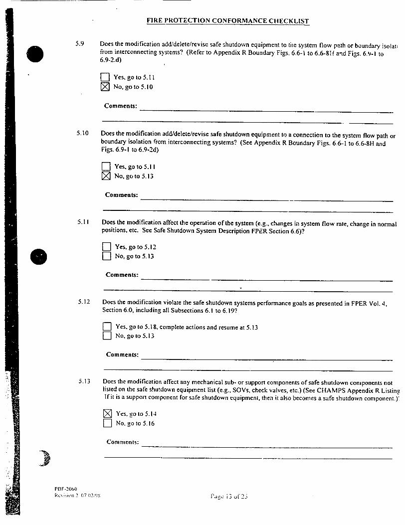
FIRE PROTECTION CONFORMANCE CHECKLIST
5.9 Does the modification add/delete/revise safe shutdown equipment to the system flow path or boundary isolati from interconnecting systems? (Refer to Appendix R Boundary Figs. 6.6-1 to 6.6-8H a'nd Figs. 6.9-1 to 6.9-2.d)
- Yes, go to 5.11
[ No, go to 5.10
Comments:
5.10 Does the modification add/delete/revise safe shutdown equipment to a connection to the system flow path or boundary isolation from interconnecting systems? (See Appendix R Boundary Figs. 6.6-1 to 6.6-8H and Figs. 6.9-I to 6.9-2d)
F] Yes, go to 5.11 [1 No, go to 5.13
Comments:
5.11 Does the modification affect the operation of the system (e.g., changes in system flow rate, change in normal positions, etc. See Safe Shutdown System Description FPER Section 6.6)?
[-I Yes, go to 5.12 E] No, go to 5. 1 3
Comments:
5.12 Does the modification violate the safe shutdown systems performance goals as presented in FPER Vol. 4, Section 6.0, including all Subsections 6.1 to 6.19?
E] Yes, go to 5.18, complete actions and resume at 5.13 [-] No, go to 5.13
Comments:
5.13 Does the modification affect any mechanical sub- or support components of safe shutdown components not listed on the safe shutdown equipment list (e.g., SOVs, check valves, etc.) (See CHAMPS Appendix R Listing If it is a support component for safe shutdown equipment, then it also becomes a safe shutdown component.)Y
[ Yes, 2o to 5.14
D No. go to 5.16
Comments:
)PlIF-2060 Rc'%i in 2 07 02 '9XPo P.Ag-ýc i 3 u (25-

FIRE PROTECTION CONFORMANCE CHECKLIST
E] Yes, go to 5. 18, complete actions and resume at 6.1
1D No, go to 6.1
Comments:
5.18 The addition/deletion/revision of safe shutdown components, sub- or support components affects sale shutdown. List the equipment and the affected systems and refer to FPER Section 8.4.4.1. RESUME checklist completion.
Safe Shutdown System(s), Components, Sub- or Support Component(s):
)Ph F-2060 l, , i~ n 2 O7,g2 ,')•X
5.14 Does the modification to the sub- or support component affect the operability of its associated safe shutdown equipment? (i.e., Failure of a support component that results in failure of a safe shutdown component)
-' Yes, go to 5.15
Z No, go to 5.16
Comments: The modified Auxiliary FW pump P-38A recirculation line will be set to operate the same as the original recirculation line.
5.15 Will the safe shutdown equipment continue to perform its function required by AOP 10A, AOP 10B, AOP 10C. and/or AOP IOD? (Ref. FPER 6.8 and 6.9)
-] Yes, go to 5.16
F-- No, go to 5.18, complete actions and resume at 5.16
Comments:
5.16 Does the modification add/delete/revise any electrical sub or support components which support the identified safe shutdown component(s) (e.g., power supplies, relays, switches, motor operators)? (Ref. Associated Circuit Analysis FPER 6.13)
-- Yes, go to 5. 17 Z No, go to 6.2
Comments:
5.! 7 Do the sub- or support components impact the operability of associated safe shutdown equipment required by AOP I0A, AOP 10B, AOP I0C, and/or AOP IOD? (Ref. FPER 6.8 and 6.9)
1)a,-c [4 co1-25
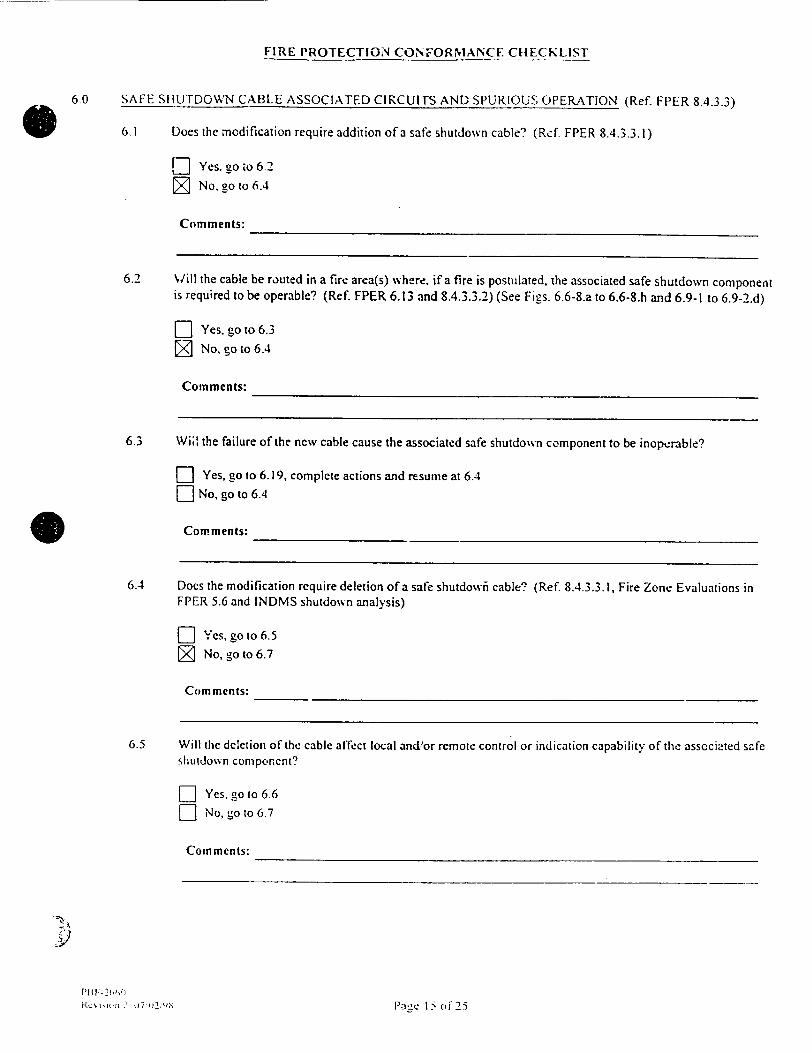
FIRE PROTECTION CONFORMANCE CHECKLIST
6.0 SAFE SHUTDOWN CABLE ASSOCIATED CIRCUITS AND SPURIOUS OPERATION (Ref. FPER 8.4.3.3)
6.1 Does the modification require addition of a safe shutdown cable? (Rcf FPER 8.4.3.3. 1)
[- Yes. go ,o 6.2
SNo, go to 6.4
Comments:
6.2 Will the cable be routed in a fire area(s) where, if a fire is postulated, the associated safe shutdown component is required to be operable? (Ref. FPER 6.13 and 8.4.3.3.2) (See Figs. 6.6-8.a to 6.6-8.h and 6.9-1 to 6.9-2.d)
FD1 Yes, go to 6.3 H No, go to 6.4
Comments:
6.3 Will the failure of the new cable cause the associated safe shutdown component to be inoperable?
D Yes, go to 6.19, complete actions and resume at 6.4
- No, go to 6.4
* Comments:
6.4 Does the modification require deletion of a safe shutdowni cable? (Ref. 8.4.3.3.1, Fire Zone Evaluations in FPER 5.6 and INDMS shutdown analysis)
D Yes, go to 6.5
J No, go to 6.7
Comments:
6.5 Will the deletion of the cable affect local and'or remote control or indication capability of the associated safe shutdown component?
D-I Yes, go to 6.6 D No, go to 6.7
Comments:
i~c• ~ilt~ 2 u7 P,.-ic Iz of 25

FIRE PROTECTION CONFORMANCE CHECKLIST
6.6 Is the affected local and/or remote control or indication capability of the associated safe shutdown component
required for Appendix R safe shutdown by A.OP IOA, AOP I 0B, AOP IOC, and/or AOP IOD? (Ref. FPER 6.8
and 6.9)
n Yes, go to 6.19, complete actions and resume at 6.7
-- No. go to 6.7
Comments:
6.7 Does the modification require revision or rerouting of an existing safe shutdown cable?
D Yes, go to 6.8
[ No, go to 6.10
Comments:
6.8 Does the rerouting of the cable maintain the sepai on of unique trains required by Appendix R to achieve safe
shutdown?
n Yes, go to 6.9
-I No. go to 6.19, complete actions and resume at 6.10
Comments:
6.9 Will the revision of the cable affect the eperability of the associated safe shutdown component?
L- Yes, go to 6.19. complete actions and resume at 6.10
[- No, go to 6. 10
Comments:
6.10 Does the modification req'iie addition or revision of a circuit connected or to be connected to safe shutdown
power supply? (Ref. FPER 8.4.3.3.2 and Fies. 6.6-8.a to 6.6-8.h and Figs. 6.9-1 to 6.9-2.d)
-- Yes, go to 6.11 [ No, go to 6.12
Comments:
IPae 16 of 25
P;IW-206fl Ike• isitm 1 07,'02,'"'
-1..'

FIRE PROTECTION CONFORMANCE CHECKLIST
6. I1 Will adequate electrical coordination between the safe shutdown power supply feeder breaker and the added or revised component breaker or fuse exist? (Ref. FPER 8.4.3.3.2.2 and 6.13.3
- Yes, go to 6.12 D No. go to 6.19. complete actions and resume at 6.12
Comments:
6.12 Does the modification require addition or revision of any non-safe shutdown circuits?
n Yes, go to 6.13 [7 No, go to 6.15
Comments:
6.13 Will !he new or reised cables be equipped with circuit breakers, fuses or some kind of cu::ent limiting device? (Ref. FPER 6.13.3.1)
- Yes, go to 6.15
D No, go to 6.14
Comments:
6.14 WiMl the new or revised cables share a common enclosure.(raceway, panel etc.) with safe shutdo%, n cables? (Ref. FI-ER 8.4.3.3.2.2 and 6.13.3.3)
--- Yes, go to 6.19, complete actions and resume at 6.! 5
-- No, go to 6.15
Comments:
6.15 Does the modification addcdelete re% ise any safe shutdown components andlor highilow pressure interfaces which could operate spuriously? (Ref. FPER Vol. 4, Section 6.14.1.1 and FPER 8.4.3.3.3. 1)
D Yes, go to 6.16 [ No, go to 6.17
Corn ments:
72 7(1. l' c 17 ol125

FIRE PROTECTION CONFORMANCE CHECKLIST
6.16 Could the addition'dcletion/revision of the spurious safe shutdown components alter system operation and prevent zhe achievement of safe shutdown? (FPER 8.4.3.3.3.1, 6.13.1.2, and 6.14)
F-1 Yes, go to 6.19, complete actions and resume at 6.17
F] No, go to 6.17
Comments:
6.17 Does the modification add/delete/revise the circuits of any safe shutdown equipment listed in FPER Vol. I, Spurious Operations Table 6.8.4.1
D Yes, go to 6.18
N ,o, go to 7.1
Comments:
6.18 Will the recGmmended resolution for mitigating the spurious operation listed in Table 6.8.4.1 remain applical after the modification?
-- Yes, go to 7.1
D No, go to 6.19, complete actions and resume at 7.1
Comments:
6.19 The modification impacts safe shutdown List the safe shutdown Llicuits ard associated components and refer FPER Section 8.4.4. 1. RESUME checklist completion.
Comments:
7.0 EFFECrs ON EXEMPTIONS/EVALUATIONS (Ref. FPER)
7.1 Is the modification proposed to be implemented in a fire zone for which an exemption is noted in the Fire Zoi Evaluation in FPER Vol. 2 and/or Vol. 3 Section 5.6?
Lf Yes, go to 7.6. complete actions and resume at 7.2
V-- No. go to 7.2
Com ments:
S[B| - U• I...

FIPE PROTECTION CONFORM".ANCE CHECKLIST
7. 2 Does the modification add delete. rev ise any safe shutdo\%n or spurious components and'or cables?
D] Yes, _o to 7.6. complete actions and resume at 7.3
rN Na. go to 7.3
Comments:
7.3 Does the modification increase the combustible loading or level of fire hazard (including intervening combustibles) above that approved in an NRC exemption in the fire zone of concern? (See fire zone evaluations for zone in Nshich the modification is planned - FPEP 5.6) The following fire zines have exemption conditions associated .%th restricting intervening combustibles. Review the fire evaluation for these fire zones in FPER Section 5.6
142 CCW Pump Room 151 SI/CS Pump Room 156 1B32 MCC Room 166 2B32 MCC Room 304 AFW Pump Room
18 Cable Spreading Room 552 SW Pump Room
D Yes, go to 7.6, complete actions and resume at 7.4
[ No, go to 7.4
Comments: Due to previously identified concerns in the Room 304, Hourly Fire Rounds are being performed. This work waill be governed by the controls prescribed by NP 1.9.9 and NP 1.9.13.
7.4 Does the modification add delete.,reise a detection or suppression system that has been credited with an NRC exemption in the fire zone of concern? (See applicable fire zone evaluation in FPER 5.6)
n Yes, go to 7.6, complete actions and resume at 7.5
[7 No. go to 7.5
Comments:
7.5 Does the modification affect any' other means of Fire protection (hatches, curbs, etc.) which formed !he basis for an NRC exemption? (See applicab!e fire zoni, evaluation in FPER 5.6)?
] Yes, -!o to 7.6. comple.e actions and resume at 7.7
E' No. eo to 7.7
(Cmments:
I -�

-IRE PROTECTION CONFORMANCE CHECKLIST
7.6 Does the modification violate a basis for the requested exemption listed in the exemption request section of the
fire zone fire evaluation in FPER Vol. 2 and'or Vol. 3, Section 5.6?
D Yes. go to 7.9
D- No, RESUME Checklist Completion
Comments:
7.7 Are the systems, components, or cables redundant to the systems, components, or cables affected by the
modification located in fire zones for wvhich other exemptions are noted in the fire zone evaluations in FPER
Vol. 2 and'or Vol. 3, Section 5.6"
F--] Ye,, go to 7.8 71 No, go to 8 1
Comments:
7.8 Does the modification violate a basis for these other exemption(s) (accessibility, low combustible loading,
barriers, equipment location, etc.) listed in the exemption request section of the fire zone fire evaluation in
FPER Vol. 2 and'or Vol. 3, Section 5.6?
E] Yes, go to 7.9. complete actio,,s and resume at 8.1
-] No, go to 8.1
Comments:
7.9 The modification violates the basis for an exemption or evaluation. List the basis affected and refer to FPER
Section 8.4.4.1. RESUME checklist completion.
Cable and Components:
8.0 EMERGENCY LIGHTING (Ref. FPER 8.4.3.5)
8.1 Does the modification add'delete,revise safe shutdown component(s) 'or which manual operation is required by
AOP 10A. AOP 10B, AOP IOC, and/or AOP IOD? (FPER Section 6.8 and 6.9)
°I,
ii'1W-2060
""-.i•.., 2 Q-1•
N No, cort o
Comments:
Paýc _0 ol 25
~~~~~~~~~~~~-O .. .t.,oa • •. -•. ,,.,, ,OK.: _--'3. - -,A .. l. , .•• .VL~ •'• ~ '• ,.- Lr _.7 • "1•+•-•.'.:
)2-`ýý

7
FIRE PROTECTION CONFORMANCE CHECKLIST
8.2 Is emergency lighting which meets the requirements of Appendix R, Section lIIJ provided at the component(s)
and access,'egress routes thereto? (FPER Section 6. 1.9 and 9. 1)
] Yes. go to 8. 4
" No, go to 8. 3
Comments:
8.3 Does the modification add emergency lighting which meets the requirements of Appendix R, Section lIIJ at the
added component(s) and access/egress routes thereto? (FPER Section 6.1.9 and 9.2)
F] Yes, go to 8.4
L No, go to 8.11, complete action and resume at 8.4
Comments:
8.4 Does the modification add/delete/revise an emergency lighting sys'.em or any emergency lights?
f Yes, go to 8.5
[ No, go to 8.7
Comments:
8.5 Is the affected portion of the emergency IFghting system required for Appendix R safe hot shutdown and/,r fire
fighting purposes?
-- Yes, go to 8.6
E- No, go to 8.7
Comments:
8.6 Does the affected portion of emergency lighting system meet the requirements for intensity, coverage, and
required battery capacity of the emergency lighting technical evaluation for Point Beach Nuciepr P!a'nt, FPER
Vol. 5, Section 9.2?
E Yes, go to 8.7
-- No, go to S. 11, complete action and resume at 8.7
Comments:
rI '-2IC7.'2 IPi c 21 of-)

FIRE PROTECTION CONFORMANCrE CIIECKL!ST
8.7 Does the modification do,'.nurade the abil.:. to pertorm firefightinL'safe shutdown activities efficienrl d ring
a blackout?
' Yes, Lo to 8.11. complete action and resume at 8.4
Z No, go to S.8
Cornments:
8.8 Does the modification involve any structural changes or equipment installations that may block the illumination
path of an emergency light?
[ Yes, go to 8.9
Z No. go to 9.1
Comments:
8.9 Is the affected emergency light required for safe shutdown (e.g.. required for illumination of safe shutdown
component. local control station. or access egress routes thereto)?
[Yes, go to S. I0
D No. go to 9.1
49 Comments:
.10 Does the affected emergency light still meet the requirements of the cmergency lighting technical evaluation for
Point Beach Nuclear Plant, FPER Vol. 5. Section 9.2.
D Yes, go to 9.1
D No, go to 8.1 1. complete action and resume at 9.1
Con, mennts:
8.11 The modification impacts on Appendix R safe shutdown compliance. List the affected position of emergency
lighting system and refer to FPI"R Section 8.4.4.1. RESUME checklist completion.
Flinet genc) Lighting SN stem:
P,\ 2 I W I ý ;"--'C o I, 2
." .1 D, I

FIRE PROTECTION CONFORMIANCE CHECKLIST
9.0 PLANT COMMUNICATIONS (Ref. FPER 8.4.3.6)
9.1 Does the modification add delete'revise plant Motorola HT-1000 Portable Radio communication systems?
[] Yes, go to 9.2
El No, go to 9.4
If yes, verify communications bettween local control stations by updating the Appendix R radio test performed
in CR92-806 and included in FPER Section 9.0.
Comments:
9.2 Is the affected portion ofplzr' -,ý.-!,unication system required for Appendi' P -safe shutdcwn and/or fire
fighting purposes? (See i- " -' ' " ' )
SYes, go to 9. LI No, go to 9.4
Comments:
9.3 Does the modification adL c- -t 're . ,. ii,; (e.g.. i' ina system, re; .ater", power suppiles, etc.) that
could impede plant comm.1, ... .'.. :ic li -•-dio tr.:!sminission or recertion? (See FPER 4.1.11)
LI Yes, go to 9.6, co'. ac• nd ,.sum at 9..
-- No, go to 9.4
Comments:
9.4 Does the modification involk e any structural changes that may impede ratio transmission reception, or other
communication means? (See FPER 4.1.11)
-- Yes. go to 9.5
[• No, goto 10.1
Comments:
9.5 Will the affected conmunica'ion system still perform its function?
-I Yes, go to 10. ' LI No, go to 9.6, complekt actions and resume at 10.1
Corn rneitts:
I I I I F -2060 .RcN i~jhq 2 07, LI' ()3 llaec 23 ot 25
i .
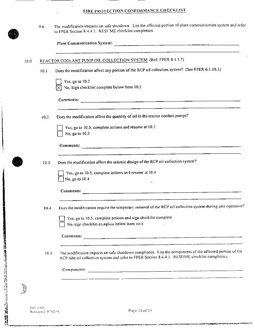
FIRE PROTECTION CONFORMANCE CHECKLIST
9.6 The modification impacts on safe shutdo%%n. List the affected portion of plant communication system and refer
to FPER Section 8.4.4.1. RES'ME checklist completion.
Plant Commnmication S stem:
10.0 REACTOR COOLANT PUMP OIL COLLECTION SYSTEM (Ref. FPER 8.4.3.7)
10.1 Does the modification aflect any portion of the RCP oil collection system? (See FPER 6.1. 10.3)
D] Yes, go to 10.2
71 No, Sign checklist complete below Item 10.5
Comments:
10.2 Does the modification affect the quantity of oil in the reactor coolant pumps?
E Yes, go to 10.5, complete actions and resume at 10.3
D No, go to 10.3
Comments:
10.3 Does the modification affect the seismic design of the RCP oil collection system?
- Yes, go to 10.5, complete actions an'i resume :t 10.4
- No, go to 10.4
Comments:
10.4 Does the moditication require the temporary removal of the RCP oil collection system during unit operation 9
-] Yes, go to 10.5, complete actions and sign checklist complete
D-] No. signr checklist criplcic below item iu.:)
Corn ments:
10.5 The modification impacts on safe shutdown compliance. List the components of the affected portion of the
RCP lube oil collection system and refer to FPER Section 8.4.4. 1. RESUME checklist completio.i.
Cornponcnts:
. kc ior. t,(_. P:we 24 of'2'

FIRE PROTECTION CONFOQNIANCE CHECKLIST
1 i.O RESULTS
If the completion of an% FPCC screening from Sections 1.0 - 10.0 indicates the modification impacts safe shutdown
compliance, then the plant fire protection or safe shutdown design basis may be affected. A 10 CFR 50.59 screening
must be performed per NP 10.3.1. Authorization of Changes, Tests, and Experiments (10 CFR 50.59), with
consideration of the FPCC information to determine if an unreviewed safety questions is involved, the design basis fire
is the accident to be considered in the 10 CFR 50.59 evaluation. The FPCC becomes part of the documentation
supporting the 10 CFR 50.59 screening and safety evaluation
Inform the NPBU Fire Protection Engineer if fire protection program commitments or compliance with 10 CFR 50,
Appendix R will be affected.
Conformance checklist completed.
Date:: S¢-/7-00•
P[aF-20ý'O kc i -. -), ý7
By: Foltynowicz, A 6:)' ,_ _ _
L'QzQ
y?.r

jQCJ NJOT OQ1 U. 0.1t.G INJ rYMC)T9F +-r~ Z c 017.I1t-. 0.Iz~s, r),piNH -Ol
/� ccTh�I
2.2Q 5: 0 .00
I.D. DEVELOPMENT
=ij2 -P-07I BAC W
kEAJ 7.:LýBEST COPY AVAILABLE
/ 0005
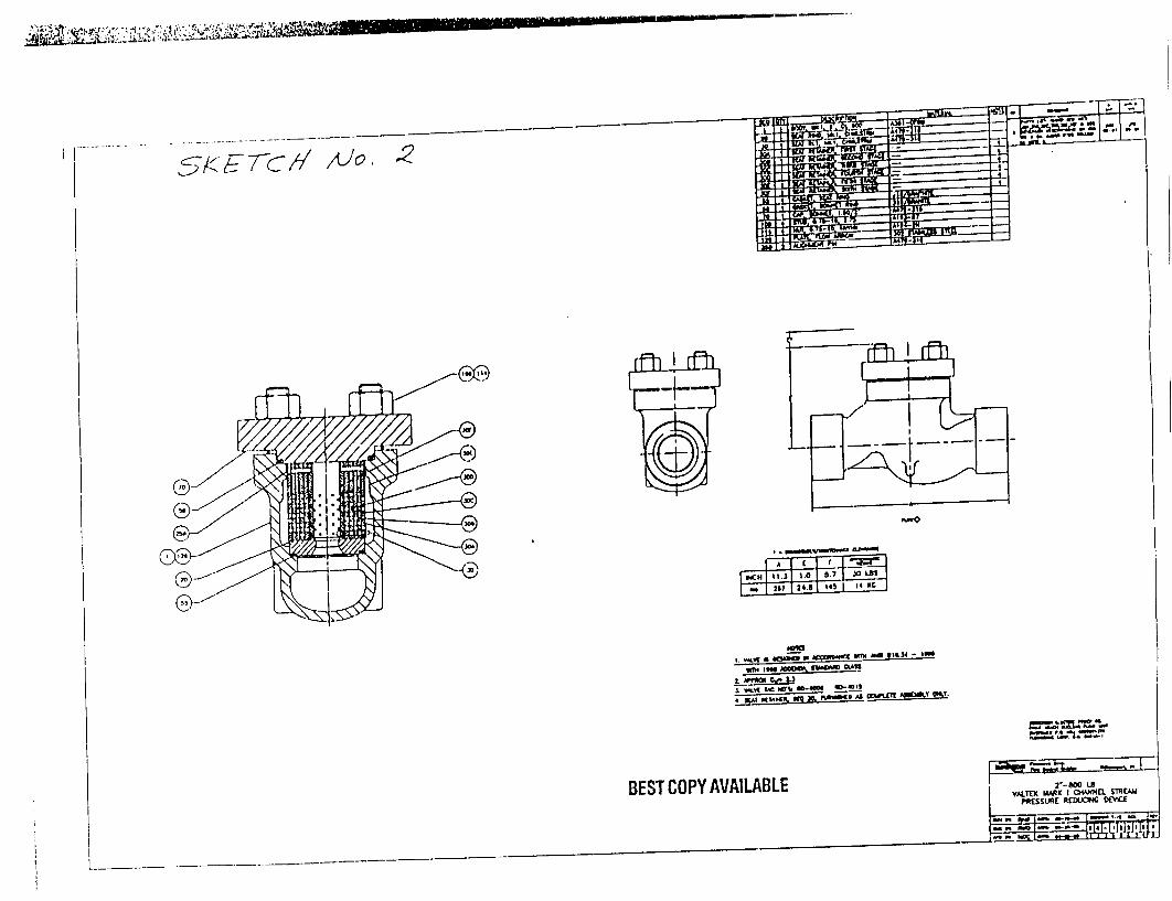
ftMo
* - -- -
M.m£ - un ~3 ar owe oW~fl onU
(
BEST COPY AVAILABLE
,5K F-7-CI 1JO1
M- -

Point Beach Nuclear Plant
FME CHECKLIST
I. WORK ORDERTPROCEDUREfEVOLUTION:
U1. ADM1INISTRATTE CONTROL EXEMMPTONS
(If any are answered "YES." General requirements continue in effect and Sectili ITV INSPE(
awe sLiU required.)
I. PioindConduit 2" Diameter or Less (nominal) or System Opening Less Than 4 Square Inches
(approximate). (see Note 1)
2. System Opening Less Than or Eoual to 4 Inches in Diameter (i.e. waterbox drair"
Between 4 O'clock and 8 O'clock ipoinung down).
3. Maintenance Activity Involving Compression,tThreaded Fmnings.
4. Maintenance/Operations Pump/Valve Repacking. ( see Note 1)
5. Maintenance/Operation Oil Changes. Oil Sampling. or Repacking of Grease in Components L
Factcry' Installed Fill/vent Potts.
6. FMB Z,)ne: 1 2 NA - Gen. Reqmt's. , c.. c one i
Recommended By (Planner):
Concurred By (Cognizant Supert'isor):
1i. ADMINISTRATIVE REQUIREMENTS: ZONE 1
(Initial Those That Apply)
I. Boundaries (Required for all Zone I F.Ef--s) Required Nc
2. Signs (Required for all F'IMA Zone 1 &2) Required
3. Pipe Darns Required (Record On FMB Material Conuoi Log)
4. FME Material Control Log (PBF-9157) *RLequired
5. Chemical Exclusion Zone ýSee Dry Fuel RequtrementSI
"Not required when Temporary Covt:rs or internal barriers are in place.
IDV. INSPECTION REQUIRED:
1. Pre-System Opening Area Inspection/Cleanup Required)
2. Final Closeout L-spection
CoinpleteReviewed By
(Siper,'isor/Leadperso,f i):
Note I - Continuously aittend svstemn-component when open. or co.
Yes/No-TIONS
Jsing
Date:
Date:
1ONE 2
3t Required
Required
COMPLETED (InitiaIJDate,
/
Date:
ver when not attended.
-0��' � B UIIBICO

INTERNAL CORRESPONDENCE
NPM 2000-0171
To: M. Schug D. Faltyrnski D. LI
T. Spencer J. P. Schroeder J. Po
From: A. Foltynowicz ,,. • "6c'--
Date: February 16, 2000
eClair l acek
EDMSFILE " I -
J. McCullum R. Chapman
Sutject: MR 99-029*A PACKAGE DISTPiBk'TION REVIEW TRANSMiTTAL
Copy To: (WIO Attachments) R. Hornak D. Sch L. Armstrong File: MI. MIR 99-029*A
)on J. Barrows W. Wilson
.5-
RU1C FES 1 2 0mU
Attached is the design package for MR 99-029*A, Auxiliary Feedwater Pump P-38A Minimum
Flow Recirc Line Orifice Replacement, for your review and comments. The supporting
documents are:
* Design Description * Design Input Checklist 6 Work Order Work Plan IWP 99-029*A * Working drawing
0 Fire Protection Conformance Checklist
* 50.59 Safety Evaluation * Documentation Update Checklist
* Bill of Materials for IWP 99-029*A
Note that not all documents are included with e eryone's package. Also, IWP 99-029-A is not
vet complete, but it is reflected in the design documents. It covers non-outage activities to
support this modification and will be submitted at a later date.
Please review the package applicable to your review and return the package with comments. I am
requesting that reviews be completed by Monday, 03/27/00. Contact me at X7411 if you require
additional information.
AF/kls
Attachrmenits BEST COPYAAVAILABLE

Ceinmrt'rd ro NulieI Ertc'4iCe
INTERNAL CORRESPONDENCE
FILEi' t
_r -M,• _
NPM 2001-0071
To: M. Schug D. Faltynski D. LeClair J. McCull
R. Geier J.P. Schroeder J. Polacek R. Chapn
J. Bousch
rom: A. Foltynowicz ? ' -/, )ate: January 24, 2001
ject: MR 99-029*Al IWP DISTRIBUTION REVIEW TRANSMITTAL
y To: (W/O Attachments)
R. Hornak D. Schnon J. Barrows W. Wilson
L. Armstrong File MI.1 MR, 99-029*A
[urn
nan
Attached is the IWP 99-029*A1, Auxiliary Feedwater Pump P-38A Minimum Flow Recirc Line
Orifice Modification, for your review and comments. The goal of this modification is to increase
the flow through the orifice.
Please review the IWP 99-029*A1 and rcturn with your comments. It is requested that reviews
be completed by February 09, 2001. Contact me at X7411 if you require additional information.
AF/kml
Attachments
BEST COPY AVAILABLE
RECTD FEB 05 2001
Ft
Sub
Cop)