planning and delivery comparison of six linac …digitool.library.mcgill.ca/thesisfile107888.pdf ·...
TRANSCRIPT

PLANNING AND DELIVERY COMPARISON OF SIX
LINAC-BASED STEREOTACTIC RADIOSURGERY
TECHNIQUES
Varun Singh Thakur
Department of Medical Physics
McGill University, Montreal
March 2012
A thesis submitted to McGill University in partial fulfillment of the requirements of the
degree of Master of Science in Medical Physics
Varun Singh Thakur 2012

i
Abstract
This work presents planning and delivery comparison of linac-based SRS
treatment techniques currently available for single lesion cranial SRS. In total, two
dedicated SRS systems (Novalis Tx, Cyberknife) and a HI-ART TomoTherapy system
with six different delivery techniques are evaluated. Four delivery techniques are
evaluated on a Novalis Tx system: circular cones, dynamic conformal arcs (DCA), static
non-coplanar intensity modulated radiotherapy (NCP-IMRT), and volumetric modulated
arc therapy (RapidArc) techniques are compared with intensity modulation based helical
Tomotherapy on the HI-ART Tomotherapy system and with non-isocentric, multiple
overlapping based robotic radiosurgery using the CyberKnife system. Thirteen patients
are retrospectively selected for the study. The target volumes of each patient are
transferred to a CT scan of a Lucy phantom (Standard Imaging Inc., Middleton, WI,
USA) designed for end-to-end SRS QA. In order to evaluate the plans, several indices
scoring the conformality, homogeneity and gradients in the plan are calculated and
compared for each of the plans. Finally, to check the clinical deliverability of the plans
and the delivery accuracy of different systems, a few targets are delivered on each system.
A comparison between planned dose on treatment planning system and dose delivered on
Gafchromic EBT film (ISP, Wayne, New Jersey, USA) is carried out by comparing dose
beam profiles, isodose lines and by calculating gamma index.

ii
Abrégé
Cette étude présente la planification et la comparaison de livraison de doses de les
techniques de traitement par accélérateur linéaire (linac) à base de radiochirurgie
stéréotactique (RCS) actuellement disponibles pour la RCS des lésions crâniennes
uniques. Au total, deux systèmes RCS (Novalis Tx, Cyberknife) et un système HI-ART
TomoTherapy avec six techniques différentes de livraison de doses sont évalués. Trois
techniques de livraison de doses d’un système Novalis Tx sont évalués: arcs dynamiques
conformationnelles, radiothérapie avec modulation d'intensité statique non-coplanaire et
les techniques de thérapie volumétrique par arc modulé (RapidArc) sont comparées avec
la tomothérapie hélicoïdale par modulation d'intensité sur le système HI-ART
TomoTherapy et la radiochirurgie robotique non-isocentrique à multiples
chevauchements du système CyberKnife. Treize patients sont rétrospectivement
sélectionnés pour l'étude. Les volumes cibles de chaque patient sont transférés sur un scan
tomodensitométrique d'un fantôme Lucy (Standard Imaging Inc, Madison, WI, Etats-
Unis) conçu pour l’assurance qualité des systèmes RCS. Afin d'évaluer les plans de
traitements, plusieurs métriques de notation de conformalité telles que l'homogénéité et
les gradients du plan de traitement sont calculées et comparées pour chacun des plans.
Enfin, dans le but de vérifier la faisabilité de livraison clinique des plans de traitements et
la précision de livraison des différents systèmes, quelques cibles sont délivrées sur chaque
système. Une comparaison entre la dose prévue sur le système de planification du
traitement et la dose délivrée sur un film de type GAFCHROMIC EBT (ISP, Wayne,

iii
New Jersey, USA) est effectuée par comparaison des profils de faisceaux de dose, des
lignes de doses de même intensité (isodose) et en calculant l'indice gamma.

iv
Acknowledgements
I have many people to express my gratitude for making this project possible.
First, I would like to thank my supervisor William Parker, co-supervisors Russell Ruo
and Emilie Soisson for their continuous support, guidance and encouragement.
Especially I would like to thank Russell for mentoring me throughout the year including
many weekends and late hours, without his guidance this thesis work would never be
possible. I also like to thank Dr. Jan Seuntjens for providing me the financial support
throughout the year.
There are a few peoples to whom I would like to extend a special thank you. I
would like to thank Robert Doucet (CHUM) for helping me with the CyberKnife. I also
like to thank Hugo Bouchard and Frederic Girard (CHUM) for helping me in film
dosimetry.
I would like to thank staff and student of the Medical Physics Unit for their
friendship, help and discussion over the last two years. In particular, I would like to
thank Martin Vallieres for generously translating my abstract to French and Greg Twork
for helping me with Tomotherapy unit.
I would like to extend my thanks to Standard Imaging Incorporation (Middleton,
WI) for providing us adopter to interface used with Lucy phantom for each of the SRS
delivery technique used in this study.
From my personal life, I would like to thank my parents, brother, sister in law and
my niece for their continuous love and faith in me.

v
Table of Contents
Abstract ................................................................................................................................. i
Abrégé ................................................................................................................................. ii
Acknowledgements ............................................................................................................. iv
Table of Contents ................................................................................................................. v
List of Figures .................................................................................................................. viii
List of Tables ...................................................................................................................... xi
Chapter 1. Introduction to Stereotactic Radiosurgery ..................................................... 1
1.1 INTRODUCTION ........................................................................................................... 1
1.2 HISTORY OF STEREOTACTIC RADIOSURGERY ................................................... 2
1.3 CLINICAL INDICATIONS FOR SRS ........................................................................... 5
1.3.1 FUNCTIONAL DISORDERS ................................................................................. 5
1.3.2 BENIGN TUMORS ................................................................................................. 5
1.3.3 MALIGNANT TUMORS ........................................................................................ 5
1.3.4 VASCULAR LESIONS ........................................................................................... 6
1.4 TECHNICAL CONSIDERATION FOR SRS ................................................................. 6
1.4.1 IMMOBILIZATION AND LOCALIZATION ........................................................ 7
1.4.2 IMAGING FOR SRS PLANNING .......................................................................... 8
1.4.3 DELIVERY MODALITIES .................................................................................... 9
1.4.4 TREATMENT PLANNING .................................................................................. 10
1.4.5 PLAN EVALUATION TOOLS ............................................................................ 12
1.4.6 PATIENT POSITIONING AND PLAN DELIVERY ........................................... 13
1.5 THESIS OBJECTIVES AND MOTIVATION ............................................................. 14
1.5.1 PLANNING COMPARISON STUDY .................................................................. 15
1.5.2 DELIVERY COMPARISON STUDY .................................................................. 15
1.6 THESIS ORGANIZATION ........................................................................................... 16
1.7 REFERENCES .............................................................................................................. 16
Chapter 2. SRS Delivery Modalities and Treatment Planning Techniques .................. 19
2.1 DELIVERY MODALITIES .......................................................................................... 19

vi
2.1.1 NOVALIS Tx ......................................................................................................... 19
2.1.2 TOMOTHERAPY ................................................................................................. 22
2.1.3 CYBERKNIFE....................................................................................................... 24
2.2 TREATMENT PLANNING SYSTEMS AND TECHNIQUES ................................... 25
2.2.1 iPlanTPS................................................................................................................. 26
2.2.2 ECLIPSE TPS ........................................................................................................ 32
2.2.3 TOMOTHERAPY TPS .......................................................................................... 35
2.2.4 MULTIPLAN TPS ................................................................................................. 38
2.3 REFRENCES ................................................................................................................. 40
Chapter 3. Materials and Methods ................................................................................. 42
3.1 PLANNING STUDY ..................................................................................................... 42
3.1.1 TARGET SELECTION ......................................................................................... 42
3.1.2 PHANTOM ............................................................................................................ 43
3.1.3 DOSE PRESCRIPTION AND PLANNING CRITERIA ...................................... 44
3.1.4 SRS TREATMENT PLANNING .......................................................................... 45
3.1.5 PLAN COMPARISON .......................................................................................... 47
3.2 SRS PLAN EVALUATION TOOLS ............................................................................ 47
3.2.1 VISUAL INSPECTION AND DOSE VOLUME HISTOGRAM ANALYSIS .... 48
3.2.2 PHYSICAL DOSE INDICES ................................................................................ 48
3.2.3 RELATION OF PHYSICAL DOSE INDICES ..................................................... 53
3.3 DELIVERY STUDY ..................................................................................................... 54
3.3.1 TARGETS .............................................................................................................. 54
3.3.2 DOSE DISTRIBUTION ANALYSIS .................................................................... 56
3.3.3 PHANTOM POSITIONING .................................................................................. 56
3.3.4 EBT 2 FILM DOSIMETRY .................................................................................. 57
3.3.5 FILM ANALYSIS ................................................................................................. 57
3.3.6 DOSE COMPARISON TOOLS (GAMMA INDEX) ........................................... 58
3.4 REFERENCES .............................................................................................................. 58
Chapter 4. Results and Discussion ................................................................................ 60
4.1 RESULTS ...................................................................................................................... 60
4.2 PLANNING STUDY ..................................................................................................... 60

vii
4.2.1 SPHERICAL TARGETS ....................................................................................... 60
4.2.2 IRREGULAR TARGETS ...................................................................................... 68
4.3 DELIVERY STUDY ..................................................................................................... 85
4.3.1 SPHERICAL TARGETS ....................................................................................... 85
4.3.2 IRREGULAR TARGETS ...................................................................................... 95
4.4 REFERENCES ............................................................................................................ 107
Chapter 5. CONCLUSIONS ........................................................................................ 109
5.1 SUMMARY OF WORK .............................................................................................. 109
5.2 FUTURE WORK ......................................................................................................... 112
Appendix .......................................................................................................................... 113
Bibliography .................................................................................................................... 118

viii
List of Figures
Figure 1.1 CT (a), MRI (b) and DSA (c) image of patient with various brain lesions. ................... 8
Figure 2.1 Novalis Tx (Courtesy of Varian and BrainLAB). ....................................................... 21
Figure 2.2 TomoTherapy® Hi·Art® treatment system (Courtesy of the TomoTherapy). ............ 23
Figure 2.3 CyberKnife® Robotic Radiosurgery System (Courtesy of Accuray). .......................... 25
Figure 2.4 A screen capture of image from iPlan treatment planning system, which displays
information provided by the system concerning the treatment plan, such as: (i) Arc arrangement
(top left window) (ii) BEV (top right window), (iii) 3D view of plan (bottom left window) (iv)
Axial plane with isodose distribution (bottom right window), and (v) Planned isocenter
coordinates (far right panel). .......................................................................................................... 30
Figure 2.5 Screenshots from iPlan planning system displays four random positions of MLC leaves
as they swept over the target. ......................................................................................................... 32
Figure 2.6 Screenshot from Eclipse TPS shows the instantaneous position of MLC leaves during
the delivery of one RapidArc. ........................................................................................................ 35
Figure 3.1 Lucy® 3D QA phantom (Standard Imaging Inc, Middleton, WI). 44
Figure 3.2 Illustration of limitation of RTOG PITV where each case shown has the same PITV of
1 but varying amounts of PTV coverage. Brown shaded area is the target and the black dashed
line is the prescription isodose line. 50
Figure 3.3 Example illustrating the co- relation between homogeneity and gradient. 53
Figure 3.4 Phantom positioning for Tomotherapy (a), Novalis Tx (b) and CyberKnife (c) systems.
55
Figure 4.1 Axial (top) and coronal plane (bottom) dose distribution of 6 mm diameter spherical
target for the Novalis cone, DCA, NCP-IMRT, RapidArc, CyberKnife and Tomotherapy
respectively (Isodose lines: pink - 12.5 Gy, red - 10 Gy, green – 7.5 Gy, blue - 5 Gy)................. 63
Figure 4.2 Axial (top) and coronal plane (bottom) dose distribution of 10 mm diameter spherical
target for the Novalis cone, DCA, NCP-IMRT, RapidArc, CyberKnife and Tomotherapy
respectively (Isodose lines: pink - 12.5 Gy, red - 10 Gy, green – 7.5 Gy, blue - 5 Gy)................. 64

ix
Figure 4.3 Paddick’s conformity index for the thirteen irregular targets. ..................................... 69
Figure 4.4 Axial isodose distribution for target with volume 2.9 cm3 shown in the blue contour
(Isodose lines: pink - 12.5 Gy, red - 10 Gy, green – 7.5 Gy, blue - 3.5 Gy). ................................. 73
Figure 4.5 Gradient index for the thirteen irregular targets. .......................................................... 74
Figure 4.6 Ratio of different isodose volumes (10 Gy, 7.5 Gy, 5 Gy, and 2.5 Gy) to the target
volume for each technique. ............................................................................................................ 76
Figure 4.7 Axial dose wash distribution for target with volume 2.1 cm3 shown in the blue contour
(Isodose color wash: pink - 12.5 Gy, red - 10 Gy, green - 7.5 Gy, blue - 3.5 Gy). ........................ 78
Figure 4.8 Conformity/gradient index for thirteen irregular targets. ............................................. 79
Figure 4.9 Homogeneity index for thirteen irregular targets. ........................................................ 80
Figure 4.10 Delivery result of 6 mm and 10 mm spherical target delivered on the Novalis Tx.
Horizontal dose profiles of axial slice are shown (black solid line represents measured profile on
film and dotted line represents calculated profile by TPS). Isodose overlay for 25%-blue, 50%-
green and 80%-red isodose line (normalized to 100% at origin). .................................................. 86
Figure 4.11 Delivery result of 6 mm and 10 mm spherical target delivered on the CyberKnife.
Horizontal dose profiles of axial slice are shown (black solid line represents measured profile on
film and dotted line represents calculated profile by TPS). Isodose overlay for 25%-blue, 50%-
green and 80%-red isodose line (normalized to 100% at origin). .................................................. 88
Figure 4.12 Delivery result of 6 mm and 10 mm spherical targets located 10 cm vertically up from
the Tomotherapy machine isocenter. Horizontal dose profiles of axial slice are shown (black
solid line represents measured profile on film and doted line represents calculated profile by
TPS). Isodose overlap for 25%-blue, 50%-green and 80%-red isodose line (normalized to 100%
at origin). ........................................................................................................................................ 90
Figure 4.13 Delivery result of 6 mm and 10 mm spherical targets placed exactly at the
Tomotherapy machine isocenter. Horizontal dose profiles of axial slice are shown (black solid
line represents measured profile on film and doted line represents calculated profile by TPS).
Isodose overlap for 25%-blue, 50%-green and 80%-red isodose line (normalized to 100% at
origin). ............................................................................................................................................ 92
Figure 4.14 Delivery results of 0.23 cm3, 8.82 cm
3 and 20.76 cm
3 irregular targets delivered using
DCA technique. Horizontal dose profiles of axial slice are shown (black solid line represents

x
measured profile on film and doted line represents calculated profile by TPS). Isodose overlap for
25%-blue, 50%-green and 80%-red isodose line (normalized to 100% at origin). ........................ 97
Figure 4.15 Delivery results of 0.23 cm3, 8.82 cm
3 and 20.76 cm
3 irregular targets delivered using
NCP-IMRT technique. Horizontal dose profiles of axial slice are shown (black solid line
represents measured profile on film and doted line represents calculated profile by TPS). Isodose
overlap for 25%-blue, 50%-green and 80%-red isodose line (normalized to 100% at origin). ..... 99
Figure 4.16 Delivery results of 0.23 cm3, 8.82 cm
3 and 20.76 cm
3 irregular targets delivered using
RapidArc technique. Horizontal dose profiles of axial slice are shown (black solid line represents
measured profile on film and doted line represents calculated profile by TPS). Isodose overlap for
25%-blue, 50%-green and 80%-red isodose line (normalized to 100% at origin). ...................... 101
Figure 4.17 Delivery results of 0.23 cm3, 8.82 cm
3 and 20.76 cm
3 irregular targets delivered on the
CyberKnife. Horizontal dose profiles of axial slice are shown (black solid line represents
measured profile on film and doted line represents calculated profile by TPS). Isodose overlap for
25%-blue, 50%-green and 80%-red isodose line (normalized to 100% at origin). ...................... 102
Figure 4.18 Delivery results of 0.23 cm3, 8.82 cm
3 and 20.76 cm
3 irregular targets located 10 cm
vertically up from the Tomotherapy machine isocenter. Horizontal dose profiles of axial slice are
shown (black solid line represents measured profile on film and doted line represents calculated
profile by TPS). Isodose overlap for 25%-blue, 50%-green and 80%-red isodose line (normalized
to 100% at origin). ....................................................................................................................... 104
Figure A Target volumes and shape of their central transversal slice (left) and reconstructed
coronal slices (right): ................................................................................................................... 113

xi
List of Tables
Table 3.1 Volumes of the thirteen targets used in this study. ........................................................ 43
Table 4.1 Summary of results for planning comparison of spherical targets. The circled data
indicates the best result for a particular criteria. ............................................................................ 62
Table 4.2 Summary of results for SRS planning of irregular targets. Paddick’s CI is Conformity
index, Paddick’s GI is gradient index, CGI is conformity-gradient index, MDPD is the
homogeneity index and SI is a symmetry index. The circled data indicates the best result for a
particular criteria. ........................................................................................................................... 68
Table 4.3 Number of cases where each technique showed the best Paddick’s CI. ........................ 71
Table 4.4 Number of cases where each technique showed the best Paddick’s GI. ........................ 77
Table 4.5 Number of cases where each technique showed the best Wagner CGI. ........................ 79
Table 4.6 Average value of CGIg and CGIc for all techniques. ...................................................... 80
Table 4.7 Number of cases where each technique showed the best MDPD. ................................. 81
Table4.8 Number of pixels passing gamma criteria for different combinations of dose difference
and distance to agreement – Novalis. ............................................................................................. 87
Table4.9 Profile shift in x and y directions for film registration – Novalis. ................................. 87
Table 4.10 Number of pixels passing gamma criteria for different combinations of dose difference
and distance to agreement - Cyberknife. ....................................................................................... 89
Table 4.11 Profile shift in x and y directions for film registration – Cyberknife. .......................... 89
Table 4.12 Number of pixels passing gamma criteria for different combinations of dose difference
and distance to agreement – Tomotherapy (off-centered targets). ................................................ 91
Table 4.13 Number of pixels passing gamma criteria for different combinations of dose difference
and distance to agreement – Tomotherapy (targets at isocenter). ................................................. 93
Table 4.14 Profile shift in x and y directions. ................................................................................ 93
Table 4.15 Number of pixels passing gamma criteria for different combinations of dose difference
and distance to agreement. ........................................................................................................... 105
Table 4.16 Profile shift in x and y directions. ............................................................................. 106

1
Chapter 1. Introduction to Stereotactic Radiosurgery
1.1 INTRODUCTION
In stereotactic radiosurgery (SRS), a high dose (>10 Gy) of ionizing radiation is
delivered to a small stereotactically localized target (< 4 cm) in a single fraction.
Historically, this technique was used only for intracranial lesions and functional disorders
such as acoustic neuroma, trigeminal neuralgia, arteriovenous malformation, brain
metastasis and other primary brain tumors. Recently the technique has been adapted for
extra-cranial targets in the lung and liver. The word stereotactic is combination of two
words, the Greek word “stereo” means “three dimensional” and the Latin word “tact”
means “touch”, the word stereotactic stands for three dimensional arrangements to touch
and the word radiosurgery means using radiation as a surgical tool.
The goal of stereotactic radiosurgery is to deliver a large obliterative dose to the
tumor with high accuracy and conformality to minimize the dose to the surrounding
healthy tissues. To meet this goal, several basic requirements for stereotactic
radiosurgery must be met including: accurate localization, mechanical precision, accurate
and optimal dose distribution and patient safety. Different organizations have set forth
their SRS recommendations such as the American Association of Physicists in Medicine
AAPM(1) and Radiation Therapy Oncology Group RTOG(2). Recommendations by the
AAPM Task Group 42 for a clinically acceptable SRS plan are: 1) Dose delivery in

2
positional accuracy shall be within ±1 mm and 2) Absolute dose delivery should be less
than of ±5% of the prescribed dose(1).
The different terms associated with cranial radiosurgery are stereotactic
radiosurgery (SRS) and stereotactic radiotherapy (SRT). Similar to SRS, SRT is also
generally used for cranial tumors but a relatively lower dose typically 2 Gy/fraction) is
delivered in multiple fractions.
1.2 HISTORY OF STEREOTACTIC RADIOSURGERY
The history of stereotactic radiosurgery can be traced back to the discovery of X-
rays by Wilhem Konrad Rontgen in 1895 and the discovery of radioactivity by Becquerel
in 1896. The credit for the invention of radiosurgery goes to Swedish neurosurgeon Lars
Leksell. Leksell's interest to develop a non invasive technique to treat intracranial lesions
led to the development of stereotactic radiosurgery(3). In 1951 Leksell used the 200 kVp
stationary X-ray beam for the first radiosurgery treatment but due to the low penetrating
power of 200 kVp X-rays this technique wasn’t efficient for tumors lying deep in the
brain.
During the 1960s, Liden and Larsson at Uppsala University used proton beams
generated from a cyclotron to treat brain lesions, they called this technique “stralkniven”
(ray knives)(4). During the same time another group of Woodruff and colleges(5) at the
University of California at Berkeley developed a similar technique, but it eventually
became clear that the use of a large proton accelerating unit was complicated and
costly(6).
In 1968, Leksell(7) was the first to develop the Gamma Knife which used 179
focused Cobalt-60 sources, this unit was installed in Sophiahemmet Hospital in

3
Stockhom, Sweden, and was used to treat arteriovenous malformations (AVMs) and
acoustic neuromas(8). In 1974 the unit was replaced with the second Gamma Knife unit
that could produce a more spherically shaped dose distribution. Irregularly shaped
tumors required multiple isocenters or “shots” in order to conform the dose distribution to
the target shape. Although, the Gamma Knife has been developed over the last five
decades, in 2007 a recent model Leksell Gamma Knife PerfexionTM
(Elekta, Stockholm,
Sweden) was introduced containing 192 Cobalt-60 sources that are further divided into 8
groups. These groups can be individually positioned to three different field sizes (4 mm,
8 mm, and 16 mm). The PerfexionTM
model includes automated features for improved
workflow, efficiency and safety. In addition it extends the use of the Gamma Knife to
stereotactic radiotherapy by offering the possibility to treat with relocatable head frames.
In the 1960's, several companies began manufacturing linear accelerators (linacs)
for radiotherapy. With the advancement in microwave technology, linacs were able to
deliver beams of different energies. Due to their lower cost and greater availability(9)
linacs became the most commonly used machine in radiation therapy. In 1984 it was
shown by Heifetz(10) that linacs could also deliver high doses to small targets and spare
normal tissue like the Gamma Knife. In addition linacs used for conventional
radiotherapy could be easily modified for use in radiosurgery. This made linear
accelerators more cost effective than buying a new Gamma Knife unit specifically
dedicated to radiosurgery only. In the following 10 years linear accelerators were widely
accepted both for radiotherapy as well as radiosurgery.
To reduce the dose to normal tissues in 1984 Betti and Derechinsky(11) developed
a multiple non-coplanar converging arc technique. Different techniques, with different

4
combinations of gantry and table angles were proposed in the following years. In 1986
Podgorsak et al.(12) developed a dynamic stereotactic radiosurgery technique using a 10
MV linac. In this technique, both table and gantry moved simultaneously during the
treatment. All the techniques up to this point were based on fixed collimators of different
diameters attached to the gantry head.
More recently, the multileaf collimator (MLC) was developed where tungsten
leaves could be used to shape the field. The use of MLC improves the dose distribution
for irregularly shaped tumors. The ability of multileaf collimators to move during the
radiosurgery procedure opens up the possibility for the clinical use of modern techniques
such as dynamic conformal arc (DCA), intensity-modulated stereotactic radiosurgery
(IMRS)(13) and most recently volumetric modulated arc therapy (VMAT)(14). Corvus
(Nomos Corporation, Sewickley, PA)(15) introduced in 1995 was one of the earlier
planning systems used to produce plans using intensity modulated beams.
In 1993 a helical delivery based approach “Tomotherapy" was introduced by
Mackie et al.(16). A linear accelerator is mounted on a ring gantry like a CT scanner.
The patient is moved through the ring gantry and an intensity modulated beam is
delivered using binary multileaf collimators. The same linear accelerator used for
imaging the patient could also be further used for treatment planning or for patient
positioning. Recently, Soisson et al.(17) have developed a technique for performing SRS
on a Tomotherapy unit with treatment plans comparable to those of conventional linac
based arc plans done with circulator collimators for spherical lesions.
A relatively new and innovative linac based system, the CyberKnife was
developed by Adler(18) and colleagues in Stanford, California. In the CyberKnife a 6

5
MV Linac is mounted on six axis industrial robotic arm. The robotic arms gives the
freedom to deliver many non-coplanar beams isocentrically or non-isocentrically. This
system incorporates a real time imaging system used to track the patient position during
the treatment. Due to the real time tracking system the CyberKnife is able to deliver a
frameless stereotactic radiosurgery treatment. Several publications in the following years
elaborate the accuracy and clinical capability of the CyberKnife(19-21).
1.3 CLINICAL INDICATIONS FOR SRS
Radiosurgery is used to treat four different types of disorders: functional
disorders, benign tumors, malignant tumors and vascular lesions(22).
1.3.1 FUNCTIONAL DISORDERS
Stereotactic radiosurgery is used to treat functional disorders that may result in
acute pain or other complications. Functional disorders treated with SRS are trigeminal
neuralgia, epilepsy, parkinsons disease and chronic pain.
1.3.2 BENIGN TUMORS
Benign tumors are well circumscribed tumors having relatively low growth rate
and do not spread to surrounding healthy tissues. Stereotactic radiosurgery is used to
treat benign tumors such as acoustic neuroma, intracranial meningiomas, vestibular
schwannomas and pituitary adenomas.
1.3.3 MALIGNANT TUMORS
Malignant tumors grow at faster rate and also spread or “metastasize” to other
parts of the body including the brain. Surgical removal of primary or metastatic tumors in

6
the brain may not be possible and this makes radiosurgery a suitable therapeutic
alternative. These tumors are more dangerous to the patient and are relatively difficult to
control.
Small malignant tumors treated with stereotactic radiosurgery or radiotherapy are
brain metastasis, gliomas, anaplastic astrocytoma, primary CNS lymphoma and
medulloblastoma.
1.3.4 VASCULAR LESIONS
The most common vascular lesion treated with stereotactic radiosurgery is
arteriovenous malformations (AVM). Under normal conditions arteries carry the oxygen
rich blood from the heart to different parts of the body and the veins bring back the
deoxygenated blood back to the heart for re-oxygenation. AVMs are clusters of blood
vessels formed in the brain, as a result of these clusters, blood is directly transferred from
the arteries to the veins bypassing brain tissue. Due to the high pressure of blood
transferred directly from the arteries to veins these clusters are prone to bleed. Bleeding
can cause pain, hemorrhage or even death.
1.4 TECHNICAL CONSIDERATION FOR SRS
In radiosurgery a very high dose of radiation is used to kill the tumor cells. This
high dose is also destructive for the surrounding normal tissues. To spare the normal
tissues it is crucial to shoot the target with maximum possible positional accuracy. This
condition is even more important in SRS because small margins are used to delineate the
tumor (to spare more normal tissue). The technical considerations during SRS treatment
are discussed in the following sections.

7
1.4.1 IMMOBILIZATION AND LOCALIZATION
To maintain the accuracy and precision desired in SRS two basic conditions are:
1) Immobilization of the patient during the treatment and 2) Exact determination of tumor
position. These conditions could be achieved in two different ways with a fixed frame
(conventional technique) or image-based frameless technique.
When using frames a trained physician screws the stereotactic frame on the
patient's head. Use of a frame solves two purposes: first because it is screwed to the
patient head the chance of head movement with respect to frame is minimized
(immobilization), second it sets up an external frame of reference with respect to which
co-ordinates of internal structures of brain could be defined (localization). To determine
the co-ordinates of internal structures a localization box with N-shaped fiducial rods is
attached to the head frame before the patient undergoes imaging. Stereotactic frames are
very precise and reliable for intracranial tumors but they are inconvenient to the patient
and are not very practical if treatment is distributed over few days as in SRT. As a result
of recent improvements in image guidance systems a relatively new approach called
frameless SRS is used in many clinics.
In frameless SRS, a non invasive mask is used to immobilize the patient. Patient
motion within the mask can result into the uncertainty of less than 1 mm. In room
imaging techniques are used to localize the patient. To place the tumor at the machine's
isocenter, images of the patient are taken and compared with digitally reconstructed
radiographs (DRRs) from the planning system. The DRRs are reference images with the
patient in the planned position. Frameless SRS is less painful to the patients and is able
to produce comparable accuracy to the conventional technique with frames(23-25).

8
1.4.2 IMAGING FOR SRS PLANNING
Diagnostic imaging modalities used in stereotactic radiosurgery are (a) Computed
Tomography (CT), (b) Magnetic Resonance Imaging (MRI) and (c) Digital Subtraction
Angiography (DSA).
CT can provide high resolution images of a patient by selecting different slice
thicknesses. To determine the co-ordinates of a tumor, a localization box with CT
fiducial rods is used. CT image acquisition depends upon the fact that different structures
have different attenuation coefficients for an incident low energy X-ray beam. In addition
to the image of internal anatomy, a CT scan can also provide the information about the
electron density of different tissues imaged. This information could be further used to
apply the heterogeneity corrections during dose calculations(26).
Because of the fact that CT image acquisition depends upon the different
attenuation coefficients of different materials, a CT scan can provide good contrast
between bony anatomy and normal brain tissue but provides less contrast between normal
tissue and the tumor (because they both have nearly the same attenuation).
(a) (b) (c)
Figure 1.1 CT (a), MRI (b) and DSA (c) image of patient with various brain lesions.

9
MRI uses the nuclear spin property of a large number of hydrogen atoms present
in the human body to produce an image. MRI typically shows greater contrast between
tumor and surrounding normal tissues than CT images. The MRI technique suffers a few
technical complications such as relatively long (~ 30 minutes) image acquisition time and
it does not provide any information about the electron density(27). Patient motion during
the long imaging time can produce artifacts in the image.
As a result of the advancement in computer technology, it is possible to
superimpose geometrically CT and MRI images using mathematical registration
techniques to utilize the information of both image modalities. This process is typically
called “fusion” or “registration”. Once the images are registered, different viewing tools
allow the planner to view the images superimposed on top of each other.
DSA is used to acquire enhanced images of blood vessels; it is mainly used to
diagnose AVMs. In DSA a radio opaque contrast medium having a selective absorption
for X-rays is used to highlight the blood vessels. In DSA, a patient undergoes the
imaging twice, first without the contrast agent (background image) and then with the
contrast agent injected into the body (contrast image). To produce the DSA image of
blood vessels, image without the contrast agent is subtracted from the image with contrast
agent. The resultant image shows only the blood vessels. To determine the co-ordinates
of the tumor a stereotactic head frame is used.
1.4.3 DELIVERY MODALITIES
There are three types of ionizing radiations/particles used in SRS treatment:
Gamma rays, Megavoltage X-rays and charged particles. The work of this thesis
concentrates on all the Linac based techniques that use megavoltage X-rays for the SRS

10
treatment. The following is a brief description of the modalities used for stereotactic
radiosurgery in this work, a more detailed discussion of these modalities is given in
Chapter 2.
Novalis Tx: The Novalis Tx system (Varian Inc., Palo Alto, CA, USA) uses
megavoltage X-rays generated from a linear accelerator. The Novalis Tx has many added
features as compared to a conventional Linac including a high definition multileaf
collimator, 6D robotic couch and 0.5 mm isocenter. It is a dedicated SRS delivery system
but may also be used for conventional radiation therapy.
Tomotherapy: The Tomotherapy Unit (TomoTherapy Inc., Madison, WI, USA)
also uses a Linac based technique. A 6 MV Linac rotates with constant velocity on a
circular ring and the patient is translated continuously through the bore. Tomotherapy can
used for SRS and for conventional radiotherapy. A binary 64-leaf multileaf collimator is
used for beam intensity modulation.
CyberKnife: The CyberKnife system (Accuray Inc., Sunnyvale, CA, USA) is
relatively new Linac based technique. A 6 MV Linac is mounted on 6 axis robotic arm.
Different collimators (cones) are used to shape the beams. The CyberKnife is capable of
using the imaging techniques to track the tumor motion during the treatment and
compensate it by re-adjusting linac positions.
1.4.4 TREATMENT PLANNING
The basic requirement of SRS planning is to deliver the maximum dose to the
tumor while minimizing the dose to the surrounding healthy tissues. During the 1950s
Lars Leksell proposed a basic idea to achieve the above requirement(3, 27-29). The idea
was to place the tumor at the center of cross-section of large number of radiation beams.

11
Because the beams are coming from different directions they deliver maximum dose to
the cross-section/tumor and less dose to the surrounding healthy tissues. The following
outlines several steps that are involved in SRS treatment planning:
Localization and imaging: The first step of SRS treatment is to determine the co-
ordinates of the tumor with respect to an external frame of reference. As the patient
comes into the clinic a stereotactic head frame is screwed on the patient skull by an expert
physician. A localization box is used to determine the co-ordinates of the tumor with
respect to the frame of reference set by the head frame. Then the patient undergoes the
imaging (CT/MRI/DSA) process.
Image import and Contouring: Once the imaging is complete, data is transferred
to a treatment planning station (TPS). In the TPS all the CT image slices are localized,
meaning the fiducials of the localizer box are found to determine the co-ordinate system
used for planning. In order to take advantage of other image modalities such as MRI,
image fusion is performed. The next step is contouring where a physician contours the
target and other organ at risks (OAR) structures on the image slices.
Prescription and Planning: Once the target and OARs are drawn, a radiosurgery
plan may be developed. Generally the dose prescribed for solitary brain metastases is
essentially determined by target size and typically is 24 Gy, 18 Gy, and 15 Gy for lesions
of diameter <20 mm, 21-30 mm, 31-41 mm as recommended by the RTOG(30). Linac
based techniques using circular collimators produce spherical dose distributions. For
irregularly shaped tumors a multiple isocenter technique must be used where spherical
distributions are added or packed together to cover the target. The result of sphere
packing is a high maximum dose due to overlapping of spherical distributions. As a

12
result, in such cases generally the prescription isodose line is 50% of the maximum dose.
Linacs equipped with MLCs are able to treat irregular targets with a single isocenter and
generally have the dose prescribed around 80% of the maximum dose.
Once the dose is prescribed by the physician, a treatment plan may be developed.
Treatments can be planned in two different ways: forward planning or inverse planning.
In forward planning, the planner determines what the parameters must be (such as beam
arrangement, beam size, and beam weights). The planner then goes through an iterative
process of adjusting the initially defined parameters to improve the dose distribution. The
success of forward planning largely depends upon the planning experience of the user. In
inverse planning, treatment goals are defined a priori by the planner and an optimization
algorithm calculates the different parameters (such as beam intensity modulation and field
size) required to meet as closely as possible the initially defined planning goals. These
days most of the planning systems are equipped with inverse planning algorithms.
1.4.5 PLAN EVALUATION TOOLS
Once the plans are ready there are many ways to compare them with each other or
with the published literature. The most common method for plan evaluation is the visual
inspection of isodose lines and dose volume histograms (DVH). Isodose lines are plotted
as percentage of prescription dose or maximum dose, whereas DVHs are a condensed
graphical representation of the dose distribution(31).
Although visual inspection of isodose lines and DVHs can provide some basic
information about the plan, different quantitative indices have been used to determine
numerical values for scoring the conformality or homogeneity of a plan. These numerical

13
values are very useful to compare the different characteristics of a given plan against
other plans.
Commonly used quantitative indices in SRS planning are: the ratio of prescription
isodose volume to target volume (PITV), Paddick's conformity index(32), maximum dose
to prescription dose ratio (MDPD), Paddick's gradient index(33), and the Wagner
Conformity/Gradient index(34). These parameters are discussed in more detail in
Chapter 3.
1.4.6 PATIENT POSITIONING AND PLAN DELIVERY
Once the suitable treatment plan is selected and approved the next step is to treat
the patient. Patient positioning is a crucial step in the success of a SRS treatment. As
explained in section 1.4.1 the desired positional accuracy in SRS treatment can be
achieved in two different ways: 1) Using stereotactic frames or 2) Frameless SRS.
In a conventional SRS treatment, a stereotactic frame is used for patient
positioning. The co-ordinates of patients internal anatomy determined during the imaging
are used for the patient positioning. The co-ordinates of the tumor are used to match its
position with the machine's isocenter. The patient is fixed to the treatment table and
printouts from the TPS indicating the location of the isocenter are taken. The printouts
are fixed to the frame/localizer and the patient is positioned according to the isocenter
location on the printouts.
In frameless SRS treatments, on board imaging techniques (stereoscopic in-room
x-ray images, planar orthogonal images, and cone-beam CT) are used for the patient
positioning. Once the patient is on the treatment couch with mask immobilization,
images of the patient are taken with on board imaging techniques and compared with

14
previously generated images from a TPS. Computer algorithms automatically
superimpose the images and calculate any shift required in patient position.
1.5 THESIS OBJECTIVES AND MOTIVATION
Stereotactic radiosurgery has been in use clinically for over 40 years and in that
time several studies have been done comparing various planning techniques and delivery
modalities(35-49). Planning comparisons may be done on the basis of the physical dose
using indices such as the PITV, conformality index, MDPD and gradient index as
mentioned in Chapter 3. Others groups(35-36) have also compared plans on the basis of
radiobiological parameters such as the tumor control probability (TCP), normal tissue
complication probability (NTCP), or biological effective dose (BED).
The primary goal of this study is to investigate delivery accuracy of six
stereotactic radiosurgery systems. In this study, three modern “state-of-the-art” SRS
systems: Novalis Tx, CyberKnife and a HI-ART Tomotherapy are evaluated. Four
delivery techniques were evaluated on a Novalis Tx system: cones, dynamic conformal
arcs (DCA), static non-coplanar intensity modulated radiotherapy (NCP-IMRT), and
volumetric modulated arc therapy (RapidArc), these techniques were compared with
intensity modulation based helical Tomotherapy on the HI-ART Tomotherapy system and
with non-isocentric, multiple overlapping based robotic radiosurgery using the
CyberKnife system.
This thesis work is divided into two sections. The first section describes the
planning study comparison between all the techniques used in our study. The second
section discusses the comparison between calculated and measured dose distributions for

15
two spherical targets (6 mm and 10 mm) and three irregular targets used in the planning
study.
1.5.1 PLANNING COMPARISON STUDY
The planning study is divided into two sections: 1) Planning for very small
spherical targets of different diameters and 2) For thirteen irregularly shaped tumors
retrospectively selected from pool of brain lesion patients previously treated on our
Novalis Tx. Treatment plans were generated for all the targets using each technique
under same set of prescription dose and constraints. These plans were compared against
each other using different quantitative indices (conformality, gradient and homogeneity)
as explained in Chapter 3.
1.5.2 DELIVERY COMPARISON STUDY
To verify the clinical deliverability of the treatment plans, a few plans were
selected to deliver on all the modalities. To verify the comparison between planned and
delivered dose a comparison between dose delivered to the film and the corresponding
dose plane from the TPS was performed. To quantify the comparison between two dose
distributions a gamma map was calculated, a further comparison between dose profiles
and isodose line was also performed.
In addition different issues associated with each modality such as: phantom
positioning, delivery time, monitoring units used and accuracy using onboard imaging
systems are discussed.

16
1.6 THESIS ORGANIZATION
Chapter 2 reviews the three delivery modalities (Novalis Tx, CyberKnife and
Tomotherapy) and the treatment planning systems used for SRS planning. Chapter 3
gives an overview of the material and methods including planning specifications,
phantom overview and film analysis used in this study. Chapters 4 and 5 discusses in
detail the result, discussion and conclusion of this work.
1.7 REFERENCES
1. Schell MC BF, Larson DA, Leavitt, DD, Lutz WR, Podgorsak EB, Wu A. . Stereotactic
Radiosurgery. . The American Institute of Physics 1995.
2. Shaw E, Kline R, Gillin M, et al. Radiation Therapy Oncology Group: radiosurgery
quality assurance guidelines. Int J Radiat Oncol Biol Phys 1993;27:1231-1239.
3. Leksell L. The stereotaxic method and radiosurgery of the brain. Acta Chir Scand
1951;102:316-319.
4. Levy RP, Schulte RW, Slater JD, et al. Stereotactic radiosurgery--the role of charged
particles. Acta Oncol 1999;38:165-169.
5. Woodruff KH, Lyman JT, Lawrence JH, et al. Delayed sequelae of pituitary irradiation.
Hum Pathol 1984;15:48-54.
6. Larsson B, Liden K, Sarby B. Irradiation of small structures through the intact skull. Acta
Radiol Ther Phys Biol 1974;13:512-534.
7. Leksell L. Cerebral radiosurgery. I. Gammathalanotomy in two cases of intractable pain.
Acta Chir Scand 1968;134:585-595.
8. Steiner L, Leksell L, Greitz T, et al. Stereotaxic radiosurgery for cerebral arteriovenous
malformations. Report of a case. Acta Chir Scand 1972;138:459-464.
9. Podgorsak EB, Pike GB, Olivier A, et al. Radiosurgery with high energy photon beams: a
comparison among techniques. Int J Radiat Oncol Biol Phys 1989;16:857-865.
10. Heifetz MD, Wexler M, Thompson R. Single-beam radiotherapy knife. A practical
theoretical model. Journal of neurosurgery 1984;60:814-818.
11. Betti O DV. Hyperselective encephalic irradiation with a linear accelerator. . Acta
Neurochir 1984.
12. Podgorsak EB, Olivier A, Pla M, et al. Dynamic stereotactic radiosurgery. Int J Radiat
Oncol Biol Phys 1988;14:115-126.
13. Webb S. Optimizing the planning of intensity-modulated radiotherapy. Physics in
medicine and biology 1994;39:2229-2246.
14. Otto K. Volumetric modulated arc therapy: IMRT in a single gantry arc. Medical physics
2008;35:310-317.
15. Carol MP. PeacockTM: A System for Planning and Rotational Delivery of Intensity-
Modulated Fields. International Journal of Imaging Systems and Technology 1995;6, 56-
61.

17
16. Mackie TR, Holmes T, Swerdloff S, et al. Tomotherapy: a new concept for the delivery
of dynamic conformal radiotherapy. Medical Physics 1993;20:1709-1719.
17. Soisson ET, Hoban PW, Kammeyer T, et al. A technique for stereotactic radiosurgery
treatment planning with helical tomotherapy. Medical dosimetry : official journal of the
American Association of Medical Dosimetrists 2011;36:46-56.
18. Adler JR, Jr., Chang SD, Murphy MJ, et al. The Cyberknife: a frameless robotic system
for radiosurgery. Stereotact Funct Neurosurg 1997;69:124-128.
19. Chang SD, Murphy M, Geis P, et al. Clinical experience with image-guided robotic
radiosurgery (the Cyberknife) in the treatment of brain and spinal cord tumors. Neurol
Med Chir (Tokyo) 1998;38:780-783.
20. Ishihara H, Saito K, Nishizaki T, et al. CyberKnife radiosurgery for vestibular
schwannoma. Minim Invasive Neurosurg 2004;47:290-293.
21. Mehta VK, Lee QT, Chang SD, et al. Image guided stereotactic radiosurgery for lesions
in proximity to the anterior visual pathways: a preliminary report. Technol Cancer Res
Treat 2002;1:173-180.
22. Khan FM. The Physics of Radiation Therapy. Lippincott Williams & Wilkins 2009.
23. Takakura T, Mizowaki T, Nakata M, et al. The geometric accuracy of frameless
stereotactic radiosurgery using a 6D robotic couch system. Physics in medicine and
biology 2010;55:1-10.
24. Chang SD, Main W, Martin DP, et al. An analysis of the accuracy of the CyberKnife: a
robotic frameless stereotactic radiosurgical system. Neurosurgery 2003;52:140-146;
discussion 146-147.
25. Breneman JC, Steinmetz R, Smith A, et al. Frameless image-guided intracranial
stereotactic radiosurgery: clinical outcomes for brain metastases. Int J Radiat Oncol Biol
Phys 2009;74:702-706.
26. Battista JJ, Rider WD, Van Dyk J. Computed tomography for radiotherapy planning. Int J
Radiat Oncol Biol Phys 1980;6:99-107.
27. Lawrence S. Chin WFR. Principles and practice of stereotactic radiosurgery: New York :
Springer,; c2008.
28. Leksell L. Stereotactic radiosurgery. J Neurol Neurosurg Psychiatry 1983;46:797-803.
29. Leksell L. The stereotaxic method and radiosurgery of the brain. Acta chirurgica
Scandinavica 1951;102:316-319.
30. Shaw E, Scott C, Souhami L, et al. Single dose radiosurgical treatment of recurrent
previously irradiated primary brain tumors and brain metastases: final report of RTOG
protocol 90-05. Int J Radiat Oncol Biol Phys 2000;47:291-298.
31. Drzymala RE, Mohan R, Brewster L, et al. Dose-volume histograms. Int J Radiat Oncol
Biol Phys 1991;21:71-78.
32. Paddick I. A simple scoring ratio to index the conformity of radiosurgical treatment plans.
Technical note. J Neurosurg 2000;93 Suppl 3:219-222.
33. Paddick I, Lippitz B. A simple dose gradient measurement tool to complement the
conformity index. J Neurosurg 2006;105 Suppl:194-201.
34. Wagner TH, Bova FJ, Friedman WA, et al. A simple and reliable index for scoring rival
stereotactic radiosurgery plans. Int J Radiat Oncol Biol Phys 2003;57:1141-1149.
35. Oliveira SC. Comparison of three linac-based stereotactic radiosurgery techniques.
Medical Physics Unit McGill University, Montreal June 2003.
36. Charpentier PE. Dosimetric evaluation of four techniques used in stereotactic
radiosurgery. Department of Medical Physics McGill University, Montreal December
2007.
37. Baumert BG, Norton IA, Davis JB. Intensity-modulated stereotactic radiotherapy vs.
stereotactic conformal radiotherapy for the treatment of meningioma located

18
predominantly in the skull base. International journal of radiation oncology, biology,
physics 2003;57:580-592.
38. Soisson ET, Mehta MP, Tome WA. A comparison of helical tomotherapy to circular
collimator-based linear-accelerator radiosurgery for the treatment of brain metastases.
American journal of clinical oncology 2011;34:388-394.
39. Yu C, Jozsef G, Apuzzo ML, et al. Dosimetric comparison of CyberKnife with other
radiosurgical modalities for an ellipsoidal target. Neurosurgery 2003;53:1155-1162;
discussion 1162-1153.
40. Schoonbeek A, Monshouwer R, Hanssens P, et al. Intracranial radiosurgery in the
Netherlands. A planning comparison of available systems with regard to physical aspects
and workload. Technology in cancer research & treatment 2010;9:279-290.
41. Cardinale RM, Benedict SH, Wu Q, et al. A comparison of three stereotactic radiotherapy
techniques; ARCS vs. noncoplanar fixed fields vs. intensity modulation. International
journal of radiation oncology, biology, physics 1998;42:431-436.
42. Hamilton RJ, Kuchnir FT, Sweeney P, et al. Comparison of static conformal field with
multiple noncoplanar arc techniques for stereotactic radiosurgery or stereotactic
radiotherapy. International journal of radiation oncology, biology, physics 1995;33:1221-
1228.
43. Khoo VS, Oldham M, Adams EJ, et al. Comparison of intensity-modulated tomotherapy
with stereotactically guided conformal radiotherapy for brain tumors. International
journal of radiation oncology, biology, physics 1999;45:415-425.
44. Podgorsak EB, Pike GB, Olivier A, et al. Radiosurgery with high energy photon beams: a
comparison among techniques. International journal of radiation oncology, biology,
physics 1989;16:857-865.
45. Solberg TD, Boedeker KL, Fogg R, et al. Dynamic arc radiosurgery field shaping: a
comparison with static field conformal and noncoplanar circular arcs. International
journal of radiation oncology, biology, physics 2001;49:1481-1491.
46. Verhey LJ, Smith V, Serago CF. Comparison of radiosurgery treatment modalities based
on physical dose distributions. International journal of radiation oncology, biology,
physics 1998;40:497-505.
47. Woo SY, Grant WH, 3rd, Bellezza D, et al. A comparison of intensity modulated
conformal therapy with a conventional external beam stereotactic radiosurgery system for
the treatment of single and multiple intracranial lesions. International journal of radiation
oncology, biology, physics 1996;35:593-597.
48. Yu C, Luxton G, Jozsef G, et al. Dosimetric comparison of three photon radiosurgery
techniques for an elongated ellipsoid target. International journal of radiation oncology,
biology, physics 1999;45:817-826.
49. Clark BG, Robar JL, Nichol AM. Analysis of treatment parameters for conformal shaped
field stereotactic irradiation: comparison with non-coplanar arcs. Physics in medicine and
biology 2001;46:3089-3103.

19
Chapter 2. SRS Delivery Modalities and Treatment Planning
Techniques
In this chapter, a description of the three linac based SRS delivery systems
(Novalis Tx, CyberKnife, and Tomotherapy) used in this study is given. Each system has
unique features that make them suitable for SRS treatments. The second part of this
chapter describes the different treatment planning techniques associated with each
delivery system.
2.1 DELIVERY MODALITIES
2.1.1 NOVALIS Tx
The Novalis Tx (Varian Inc., Palo Alto, CA, USA) is designed for both image
guided radiosurgery and conventional radiotherapy. The unit comes with three photon
energy modes: 6 MV photons, 18 MV photons and a special high dose rate
(1000MU/min) 6 MV SRS photon beam. Different components of Novalis Tx such as
gantry head and couch are designed to meet the high mechanical accuracy required for
SRS treatment. The Novalis Tx is equipped with a high definition multileaf collimator
(HD 120 MLC). The HD MLC contains 120 leaves including 64 central leaves of 2.5
mm width and 56 peripheral leaves of 5 mm width. Whereas a conventional linac
typically has a minimum leaf width resolution of 5 mm, the smaller leaf width of the HD

20
MLC allows for greater conformality to irregularly shaped tumors. In addition it also
comes with cones of varying diameter (4 mm to 15 mm) for treating spherical targets.
Image-guidance is used to achieve the desired localization accuracy. The Novalis
Tx is equipped with a stereoscopic kV X-ray imaging system (ExacTrac X-ray 6 degree
of freedom) (BrainLAB, Feldkirchen, Germany)(1) and kV X-ray on board imaging
(OBI) system capable of acquiring cone beam computed tomography (CBCT) and planar
2D kV X-ray images. The ExacTrac X-ray 6D image guided radiotherapy system
consists of an infrared (IR) based optical positioning system and kV X-ray imaging
system. The IR system contains two cameras used to track the spherical infrared markers
affixed to an array that attaches to the patient immobilization mask. The position of IR
reflecting markers can be determined to an accuracy of less than 0.3mm(2). The
stereoscopic kV X-ray imaging system contains two floor mounted X-ray tubes and two
flat panel detectors mounted in the ceiling. For the patient positioning, initial setup is
performed by using the IR system, once the patient is aligned according to external IR
markers further corrections are applied on the basis of the patient's internal anatomy.
Two X-ray images are taken by using the kV X-ray imaging system, these two images are
further compared with the digitally reconstructed radiographs (DRR) reconstructed from
the CT scan of the patient.

21
Figure 2.1 Novalis Tx (Courtesy of Varian and BrainLAB).
The comparison can be done manually or by using image fusion algorithms
available on the ExacTrac system, two options available for comparison are 3D fusion or
6D fusion. 3D fusion calculates offsets in three translational directions whereas 6D
fusion calculates offsets in three translational directions as well as in three rotational
directions.
In addition to ExacTrac, the Novalis Tx also has an integrated on-board imaging
(OBI) system capable of acquiring Cone Beam CT (CBCT) and planar 2D x-ray images.
The OBI system consists of an additional kV x-ray source and detector that are attached
to the sides of the gantry. CBCT is advantageous because it provides a 3D volumetric
image for matching with the planning CT. Most often the CBCT and 2D x-ray images
may be used as a second verification of the position determined by the ExacTrac system.
The Novalis Tx is also equipped with a flat panel detector for MV portal imaging with the
treatment beam.

22
Finally, the Novalis Tx also features a 6D robotic couch that can move in three
translational as well as three rotational directions that includes pitch, roll and yaw. The
capability of three rotational motions in addition to translational motions improves the
overall patient positioning capability of the system. The robotic couch is capable of
repositioning the patient using the deviations detected from the imaging systems to a sub
millimeter level of accuracy.
2.1.2 TOMOTHERAPY
Tomotherapy (TomoTherapy Inc., Madison, WI, USA) a 6 MV Linear
accelerator is rotating with constant velocity on a circular ring and delivers an intensity
modulated beam using a binary multileaf collimator(3). The linear accelerator can also be
used to take MVCT images of the patient that are used for the patient setup by correlating
the patient's internal structure with the machine's co-ordinates. For SRS patient
positioning a frame is used for patient immobilization and an MVCT image of the patient
is taken just before the treatment and compared with the planning CT to calculate any
required shift.
The Tomotherapy unit has primary jaws that can be opened to three different
widths (1.0, 2.5 and 5.0 cm) and a binary MLC that can produce a maximum field width
of 40 cm to generate the maximum field size of 5 cm x 40 cm. The binary MLC contains
64 leaves of tungsten with 6.25 mm leaf width projected at isocenter. The smallest field
size at isocenter is 6.25 mm x 10 mm produced by one leaf open and field width of 1 cm.
The beam is modulated by opening or closing the MLC leaves and does not have a
flattening filter to flatten the beam profile.

23
Figure 2.2 TomoTherapy® Hi·Art® treatment system (Courtesy of the TomoTherapy).
For MVCT imaging, the operator can chose the “Fine”, “Normal” or “Coarse”
setting that corresponds to slice width of 2 mm, 4 mm and 6 mm respectively. It has been
shown that MVCT image guidance can be used for stereotactic localization(4, 5); in
addition, MVCT images can be used for the dose calculations in treatment planning(6).
Contrast enhanced MRI images can be fused with the MVCT images using different
algorithms. Use of MVCT for planning has the advantage of using the same image both
for planning and for localization.
In contrast to conventional linac based techniques, the Tomotherapy does not
require the target to be placed at the machine's isocenter. For cases where multiple
tumors are present, such as brain metastasis, the Tomotherapy could be treatment of
choice because all the targets are treated at the same time so the patient does not need
repositioning for each target as required in conventional linac based SRS treatments.

24
2.1.3 CYBERKNIFE
The CyberKnife (Accuray Inc., Sunnyvale, CA, USA) is a relatively new linac
based radiotherapy system dedicated to stereotactic radiosurgery. A 6 MV Linac is
mounted on robotic arm that can move with six degrees-of-freedom. The CyberKnife can
produce non-isocentric dose delivery and is not restricted to intracranial tumors only(7).
The CyberKnife is able to produce a dose rates between 300 and 1000 cGy/minute and
can shape the beam using different collimators (5 mm to 60 mm).
The CyberKnife also uses a stereoscopic x-ray system for image guidance and
target tracking. Two low energy kV X-ray tubes are attached to the ceiling and two flat
panel amorphous silicon detectors are embedded in the floor on both sides of patient.
These detectors can continuously take images and compare them with previously
generated digitally reconstructed radiographs (DRRs) both for the initial patient setup as
well as to track the patient setup during the treatment. If there is any change in patient
position during the treatment than that information is detected and transferred to the
robotic arm attached to the Linac. The robotic arm then compensates for patient
positioning changes by adjusting the linac position. In addition, an independent
respiratory tracking system may be used for tracking target motion due to patient
respiration. The CyberKnife can use up to 1600 beams coming from different directions
and they may be focused on different parts of the tumor using a non-isocentric beam
arrangement.

25
Figure 2.3 CyberKnife® Robotic Radiosurgery System (Courtesy of Accuray).
Because the maximum dose is not delivered to isocenter but distributed over the
tumor volume, the advantage of using non-isocentric beam arrangement over the
conventional isocentric beam arrangement is that it can produce a more conformal and
homogeneous plan especially for large tumors with large dose gradients. The combined
total system accuracy of CyberKnife is reported to be sub-millimeter(8).
2.2 TREATMENT PLANNING SYSTEMS AND TECHNIQUES
In the present work all the linac based techniques currently available at the time
were studied and compared. In total three different systems, the Novalis Tx, CyberKnife
and the Tomotherapy with six different planning techniques were evaluated. The study
included four techniques that may be delivered on the Novalis Tx: cones, dynamic
conformal arc (DCA), non-coplanar intensity modulated radiotherapy (NCP-IMRT) and

26
volumetric arc therapy (RapidArc). Finally, two other delivery techniques were
compared: robotic radiosurgery using the CyberKnife system and the helical
Tomotherapy on the HI-ART TomoTherapy system.
2.2.1 iPlanTPS
In this study the iPlan v4.1 (BrainLAB, Feldkirchen, Germany) treatment
planning system was used for dynamic conformal arc (DCA) and non coplanar intensity
modulated radiotherapy (NCP-IMRT) planning techniques. The different steps followed
to plan a stereotactic radiosurgery case on iPlan for both of these techniques are: (i)
Acquisition of patient's diagnostic images, (ii) CT localization, (iii) Image fusion of MR
and CT, (iv) Structure definition, (v) Selecting the isocenter and beam arrangements, and
(iv) Dose calculations.
2.2.1.1 CALCULATION ALGORITHM
iPlan uses the pencil beam convolution (PBC) algorithm for dose calculations in
DCA and NCP-IMRT techniques. In the PBC dose algorithm, the incident beam is
divided into many small pencil beams. The BrainLAB pencil beam dose algorithm is
based on a published model by Mohan et al.(9, 10).
The following is the dose calculation equation for the pencil beam algorithm in
iPlan(11):
(2.1)

27
Where
is monitor units applied to the linac.
is nominal linac output, giving the ratio between absolute dose, measured in a
water phantom for an open field (calibration field size) at a calibration depth , divided
by the amount of MU applied.
is size of equivalent squared jaw field.
is size of equivalent squared MLC field.
is radiological path length of the beam from the tissue surface to the observation
point, corrected for tissue density inhomogeneities.
is source-surface distance of central beam.
is source-isocenter distance.
is depth of observation point in tissue.
is the depth of point where and scatter factor where measured.
is total scatter factor, describing the relative output factor for a square
MLC and jaw field.
is the tissue maximum ratio for the square field equivalent to the MLC
and jaw settings in depth
is
is idealized dose distribution in depth with
is
and y analogue.
and is idealized dose distribution (IDD).

28
IDD for a collimator with an arbitrary shape is the two dimensional convolution of
polyenergetic pencil beam kernel with the photon fluence. It is defined as
(2.2)
The photon fluence in an isocentric plane perpendicular to the central beam at a depth d is
given by
.
(2.3)
Where (x,y) is the fluence matrix in isocenter plane and is the radial factor
giving the photon fluence at a distance from the central beam at a depth d
in the phantom.
2.2.1.2 DYNAMIC CONFORMAL ARC (DCA)
In DCA, an arc consists of the gantry rotating around the patient while the couch
angle is a fixed. During gantry motion, the positions of MLC’s leaves are continuously
changing to match the target shape as viewed in the beams eye view (BEV). A typical
DCA plan will consist of 4 or more arcs. The advantages of using multiple non-coplanar
arcs is the dose outside the tumor boundaries is spread over a larger volume resulting in
more normal tissue sparing at high dose levels but a larger volume of normal tissue
receiving a low dose.
In SRS planning with DCAs, the planner places the isocenter at the center of the
target and adds suitable arc arrangements. The planner can chose any practical
29
combination of gantry rotation and couch angles. For each arc, the iPlan software is able
to optimize the collimator angle to best match the leaf positioning with the target shape
over the whole arc range.
DCA planning allows the user to view the BEV at increments of 10o along each
arc. These BEVs allow the user to readjust the position of individual leaves to get the
best target conformality. To account for beam penumbra a margin of 1 mm could be used
around the target for MLC leaf positioning.
Other parameters the planner may change to optimize the plan are: the gantry start
and stop angles for each arc, the number of arcs and the weighting of each arc. Once the
plan satisfies the requirements set by the oncologist, the plan is ready for further
verification and approval.

30
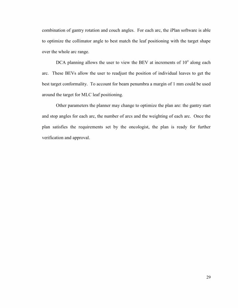
Figure 2.4 A screen capture of image from iPlan treatment planning system, which displays information
provided by the system concerning the treatment plan, such as: (i) Arc arrangement (top left window) (ii)
BEV (top right window), (iii) 3D view of plan (bottom left window) (iv) Axial plane with isodose
distribution (bottom right window), and (v) Planned isocenter coordinates (far right panel).
Figure 2.4 shows a screenshot from the iPlan treatment planning system, which displays
information provided by the system concerning the treatment plan, such as: arc
arrangement, BEV, axial plane with isodose lines superimposed, 3D view of plan and
miscellaneous information such as the co-ordinates of the isocenter.
(i)
(iv)
(v)
(iii)
(ii)
31
2.2.1.3 NON COPLANAR INTENSITY MODULATED RADIATION THERAPY
(NCP-IMRT)
Non-coplanar beam arrangement use different combinations of couch and gantry
angels. Because there is no overlapping of beams coming from opposite directions, non
coplanar beam arrangements improve the dose fall off outside the tumor boundaries and
reduce the volume of low isodose lines. Intensity modulated radiation therapy (IMRT)
uses many beams coming from different directions to achieve a highly conformal plan. In
IMRT, the intensity of the beam is modulated resulting in a non uniform deposition of
dose in the target(12), a combination of many such beams can result in highly conformal
distribution. The idea of modulating the intensity of the beam is very useful when the
tumor lies adjacent to an organ at risk or even when tumor is wrapped around critical
structures.
In NCP-IMRT, multiple static beams are used, each single beam produces a non
uniform dose distribution but the combination of all the non uniform beams can result in a
uniform and conformal total dose distribution in the target. For SRS, a non-uniform yet
conformal dose distribution may also be achievable depending on the requirements of a
particular case.
IMRT often uses inverse planning approach; after the planner has added several
non-coplanar beams, the planner defines the prescription dose, dose-volume or dose
volume histogram (DVH) constraints for the target and critical structures, and weighting
or priority for each structure. An optimization algorithm is then used to calculate the
optimized fluence for each beam to fulfill these constraints. The iPlan optimization
algorithm uses a Maximum Likelihood Estimator with dynamically changing penalization

32
or “Dynamically Penalized Likelihood algorithm”(11). iPlan comes with an interactive
feature; it can generate four alternative plans with different weightings for sparing organs
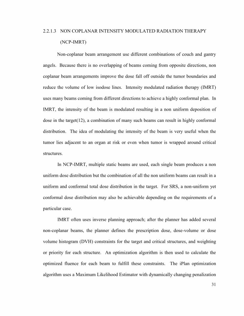
at risk. The IMRT uses sliding window technique to deliver the fluence as shown in
figure 2.5 MLC leaves slide over the target from one side to other.
Figure 2.5 shows a screenshot from the iPlan treatment planning system, it
displays four random positions of MLC leaves as they swept over the target during the
delivery of one IMRT beam.
Figure 2.5 Screenshots from iPlan planning system displays four random positions of MLC leaves as
they swept over the target.
2.2.2 ECLIPSE TPS
In this study the Eclipse TPS (v8.6, Varian Medical Systems) treatment planning
system was used for the RapidArc planning technique.

33
2.2.2.1 CALCULATION ALGORITHM
The Eclipse TPS uses the Analytical Anisotropic Algorithm (AAA)(13, 14) which
is a 3D pencil beam convolution superposition algorithm. The broad clinical beam is
divided into small beamlets and the dose calculation uses separate convolution models for
the primary photon, scattered photon and electron contamination components. The final
dose distribution is obtained by the superposition of each dose component. For the
homogeneous case, the dose is found as follows.
The following equation(15) is used to calculate the energy distribution from an
arbitrary beamlet :
(2.4)
Where:
is photon fluence.
is energy deposition density function.
is photon scatter kernel.
The following equation is used to determine the energy distribution from an arbitrary
beamlet due to electron contamination:
(2.5)

34
Where:
is electron fluence.
is energy deposition density function.
is scatter kernel for contaminating electrons.
The absorbed energy at an arbitrary calculation point is obtained by superposition of the
contribution from photons and from electrons (for the homogeneous case):
(2.6)
Where:
is dose contribution from primary photons.
is dose contribution from scattered photons.
is dose contribution from contaminating electrons.
2.2.2.2 VOLUMETRIC MODULATED ARC THERAPY (RapidArc)
Volumetric modulated arc therapy(16) was proposed by Otto in 2007, VMAT uses
an optimization technique to sample the MLC apertures for different gantry angles as the
gantry rotates around the patient. In the beginning as proposed by Otto a single gantry
arc of 360o was proposed but recent studies(17, 18) have shown that use of more than one
arc results in a more conformal and more homogeneous dose delivery.

35
RapidArc is a type of IMRT where the planner must define the prescription, DVH
constraints and priorities for each target or structure in the optimization. Also, the
planner must define for each arc the table position and the start and stop positions for the
arc. In contrast to IMRT where each beam is at a static gantry position, in RapidArc the
gantry is rotating around the patient at a fixed couch angle and the radiation beam is on
during the full arc delivery. The individual multileaf collimator leaves move dynamically
to form various apertures as the gantry moves. In comparison to IMRT, RapidArc
reduces the total number of MUs as well as the total time required to deliver the plan.
Figure 2.6 shows a screenshot from the Eclipse treatment planning system, it
displays four random positions of MLC leaves during the delivery of one RapidArc.
Unlike in NCP-IMRT where the sliding window technique is used, in RapidArc the MLC
leaves form many small apertures to modulate the beam.
Figure 2.6 Screenshot from Eclipse TPS shows the instantaneous position of MLC leaves during the
delivery of one RapidArc.
2.2.3 TOMOTHERAPY TPS
The Tomotherapy TPS (v3.1.4.23, Tomotherapy) is used to plan patients to be
treated on the Tomotherapy.

36
2.2.3.1 CALAULATION ALGORITHM
The Tomotherapy uses a convolution superposition algorithm for dose
calculations(19-23). To calculate the dose from a mono-energetic beam, the following
equation is used:
(2.7)
Where:
is the convolution kernel for photon with energy hv.
is the total energy released per unit of mass.
For poly-energetic beam, the dose in a homogeneous phantom is calculated by using
equation:
(2.8)
Where:
is the total energy released per unit of mass for poly-energetic
beam.
is the convolution kernel.

37
2.2.3.2 HI-ART HELICAL TOMOTHERAPY
For the Tomotherapy system, the TomoTherapy Hi-ART TPS (v3.1.4.23,
Tomotherapy) was used for treatment planning.
In the Tomotherapy planning, the first step is to calculate the initial un-modulated
distribution called a beamlet calculation. For the planning calculations, TPS divides the
360º full gantry rotation into 51 static projections. Each projection has 64 beamlets (64
MLC leaves) so a single gantry rotation has a total 3264 beamlets. Several planning
parameters must be assigned at this stage such as the field width, pitch, overlap priority
and calculation grid size. The initial planning constraints for the targets and OARs also
entered at this point.
The couch travels continuously in the superior direction and the gantry rotates
around the couch at a constant rate. The planning system determines the speed of gantry
rotation for every plan; possible speeds of gantry rotation are from 4 rotations per minute
to 1 rotation per minute.
At this step modulation factor, maximum and minimum dose penalty for target
and DVH coverage are defined. During optimization, the uniform intensity assigned to
beamlets earlier is re-optimized on the basis of newly assigned constrains. Every iteration
uses dose calculations of previous iteration for re-optimization. In the Tomotherapy, an
iterative least square minimization approach is used to optimize the plan. The
Tomotherapy planning system uses an objective function that favors homogeneous dose
distribution in the target(24). However for spherically shaped targets a planning
technique(25) was used to force the system to produce non-homogeneous dose
distributions normally required in SRS.

38
2.2.4 MULTIPLAN TPS
All of the CyberKnife plans are done with the Multiplan TPS (v3.5, Accuray).
2.2.4.1 CALCULATION ALGORITHM
The CyberKnife uses a ray tracing dose calculation algorithm to calculate the dose
deposited to a target voxel by each beam(26). The following equation is used to calculate
the dose per MU to each target voxel:
(2.9)
Where:
Depth d=15 mm and SAD=800 mm is the point where output is defined.
is the average dose per history at a voxel of interest.
is the average dose per history at output
specification point of the collimator.
is dose per MU at output specification
point for the collimator.
2.2.4.2 INVERSE PLANNED CONE TECHNIQUE
The advantage of the CyberKnife’s design is its capability of continuous image
guidance during the treatment delivery. Due to this image tracking system, the use of a
skeletal fixation system is unnecessary for the CyberKnife treatment. Different sets of
cones are used to produce a beam of desired diameter and the planner can choose one or

39
more cones from the set of 12 available cones. These collimators can be changed
manually or automatically as the treatment requires. In the current version of the
CyberKnife, cones are replaced with variable aperture collimator called an “Iris” which is
capable of producing 12 field diameters ranging from 5 to 60 mm at SAD of 800 mm.
The Iris variable aperture consists of two banks (upper bank and lower bank) of 6
tungsten plates each and each bank produces a beam of hexagonal aperture. Two banks
are offset by 30° resulting into a beam of dodecahedral aperture. The use of a variable
aperture collimator reduces the time required to change the cone(27).
For planning, once the prescription dose is assigned planner can chose total
number of beams and number of collimators for each plan. A linear optimization
algorithm determines the beam geometry and beam weight required to deliver the
prescribed dose. Use of large number of beams and more than one cone can improve the
plan conformality and gradient but it increase the total treatment delivery time. To
further improve the dose gradient the planner has option to use ring structures around the
target as avoiding structures.
The Multiplan System has two planning options available(27), isocentric
planning and conformal planning. Isocentric planning can be further done in two ways:
forward planning where evenly weighted beams are isocentrically placed at the target or
inverse planning where non-evenly weighted beams are isocentrically placed at the target.
In conformal planning, beams are placed at randomly selected points on the surface of a
target and the optimization algorithm calculates the weight of each beam.
For the plan optimization, Multiplan comes with two optimization approaches:
simplex optimization and iterative optimization. The advantage of using the iterative

40
algorithm over the simplex algorithm is that the iterative algorithm always gives a
solution and disperses the beams across the multiple robotic nodes. On the other hand a
disadvantage of these plans is the increased time required to deliver the treatment(26).
2.3 REFRENCES
1. Jin JY, Yin FF, Tenn SE, et al. Use of the BrainLAB ExacTrac X-Ray 6D system in
image-guided radiotherapy. Med Dosim 2008;33:124-134.
2. Wang LT, Solberg TD, Medin PM, et al. Infrared patient positioning for stereotactic
radiosurgery of extracranial tumors. Comput Biol Med 2001;31:101-111.
3. Mackie TR, Holmes T, Swerdloff S, et al. Tomotherapy: a new concept for the delivery
of dynamic conformal radiotherapy. Medical Physics 1993;20:1709-1719.
4. Forrest LJ, Mackie TR, Ruchala K, et al. The utility of megavoltage computed
tomography images from a helical tomotherapy system for setup verification purposes.
International journal of radiation oncology, biology, physics 2004;60:1639-1644.
5. Welsh JS, Bradley K, Ruchala KJ, et al. Megavoltage computed tomography imaging: a
potential tool to guide and improve the delivery of thoracic radiation therapy. Clinical
lung cancer 2004;5:303-306.
6. Meeks SL, Harmon JF, Jr., Langen KM, et al. Performance characterization of
megavoltage computed tomography imaging on a helical tomotherapy unit. Medical
physics 2005;32:2673-2681.
7. Adler JR, Jr., Chang SD, Murphy MJ, et al. The Cyberknife: a frameless robotic system
for radiosurgery. Stereotact Funct Neurosurg 1997;69:124-128.
8. Chang SD, Main W, Martin DP, et al. An analysis of the accuracy of the CyberKnife: a
robotic frameless stereotactic radiosurgical system. Neurosurgery 2003;52:140-146;
discussion 146-147.
9. Mohan R, Chui C, Lidofsky L. Energy and angular distributions of photons from medical
linear accelerators. Med Phys 1985;12:592-597.
10. Mohan R, Chui C, Lidofsky L. Differential pencil beam dose computation model for
photons. Med Phys 1986;13:64-73.
11. BarinLAB G. Technical Reference Guide, Revision 1.0, BrainLAB Physics. 2008.
12. Webb S. The physical basis of IMRT and inverse planning. Br J Radiol 2003;76:678-689.
13. Ulmer W HD. A Triple Gaussian Pencil Beam Model for Photon Beam Treatment
Planning. 2. Med. Phys;5 (1995) 25-30.
14. Ulmer W HD. Corrected Tables of the Area Integral I(z) for the Triple Gaussian Pencil
Beam Model. Z. Med. Phys.;7 (1997) 192-193.
15. Janne Sievinen WU, Wolfgang Kaissl. AAA Photon Dose Calculation Model in
Eclipse™.
16. Ottoa K. Volumetric modulated arc therapy: IMRT in a single gantry arc. Med. Phys. 35
„1…, January 2008 2007.
17. Verbakel WF, Cuijpers JP, Hoffmans D, et al. Volumetric intensity-modulated arc
therapy vs. conventional IMRT in head-and-neck cancer: a comparative planning and
dosimetric study. Int J Radiat Oncol Biol Phys 2009;74:252-259.

41
18. Clivio A, Fogliata A, Franzetti-Pellanda A, et al. Volumetric-modulated arc radiotherapy
for carcinomas of the anal canal: A treatment planning comparison with fixed field
IMRT. Radiother Oncol 2009;92:118-124.
19. Mackie TR, Scrimger JW, Battista JJ. A convolution method of calculating dose for 15-
MV x rays. Med Phys 1985;12:188-196.
20. Mackie TR, Bielajew AF, Rogers DW, et al. Generation of photon energy deposition
kernels using the EGS Monte Carlo code. Phys Med Biol 1988;33:1-20.
21. Papanikolaou N, Mackie TR, Meger-Wells C, et al. Investigation of the convolution
method for polyenergetic spectra. Med Phys 1993;20:1327-1336.
22. Mackie TR, P. J. Reckwerdt, J. Purdy, W. Grant III, J. Palta, B. Butler and C. Perez.
Madison, WI,. The convolution algorithm in IMRT. 3-D Conformal and Intensity
Modulated Radiation Therapy. Advanced Medical Publishing Inc.: 179-90. 2001.
23. Mackie TRaRPJOGH, and Shepard D M. Convolution/superposition photon dose
algorithm. General Practice of Radiation Oncology Physics in the 21st Century A. S. a.
D. Mellenberg. College Park, MD, American Association of Physicists in Medicine: 39-
56. 2000.
24. TomoTherapy Planning Guide Inc. Madison, WI 2007.
25. Soisson ET, Hoban PW, Kammeyer T, et al. A technique for stereotactic radiosurgery
treatment planning with helical tomotherapy. Medical dosimetry : official journal of the
American Association of Medical Dosimetrists 2011;36:46-56.
26. Accuray. Physics Essentials Guide, 2007.
27. CyberKnife A. Equipment specification, 2009.

42
Chapter 3. Materials and Methods
A brief discussion about the phantom, targets, and dose prescription is provided in
the first part of the chapter. The second part of the chapter contains discussion about
phantom positioning, film dosimetry, and film analysis for the delivery study.
3.1 PLANNING STUDY
3.1.1 TARGET SELECTION
Two types of target volumes were used for the study: 1) Spherical targets and 2)
Irregular patient tumors.
3.1.1.1 SPHERICAL TARGETS
A selection of spherical targets was used to compare the ability of each planning
modality for treating very small target volumes. Using drawing tools available on eclipse
TPS two spherical targets of diameters 6 mm and 10 mm were created.
3.1.1.2 IRREGULAR TARGETS
A selection of irregular tumor volumes of various shapes and sizes were used to
compare the effectiveness of each planning modality studied. Target details are shown in
Table 3.1. Thirteen patients with brain lesions that were treated in the Montreal General
Hospital (MGH) were retrospectively selected for this study. Patient selection was based
on target volume size that ranged between 0.23 - 20.76 cm3 with a mean volume of 4.7 ±
5.3 cm3.

43
N# Target Volume (cm3)
1 1.6
2 1.9
3 8.8
4 2.9
5 2.5
6 20.8
7 3.2
8 3.3
9 4.0
10 2.1
11 0.2
12 5.4
13 4.7
Table 3.1 Volumes of the thirteen targets used in this study.
3.1.2 PHANTOM
The Lucy phantom (Standard Imaging Inc., Middleton, WI, USA) Figure 3.1 was
used for planning and delivery verification in this study. It is a spherical acrylic phantom,
designed for end to end quality assurance tests for stereotactic radiosurgery. The Lucy
phantom comes with adaptors to interface to each of the SRS delivery systems used in the
study and can be used for accurate SRS treatment delivery verification. The phantom is
divided into two hemispheres so that a film cassette may be inserted in between the
hemispheres. In this study a 3 inch Gafchromic EBT 2 film (ISP, Wayne, New Jersey,
USA) is inserted into the film cassette for 2D measurement verification. The cassette is
inserted into the hemisphere so that the position of the film is at the center of the
phantom. The film plane in addition could be rotated so that the film is aligned with the
coronal or sagittal plane. Five sharp markers in the cassette are used to produce five
impressions on the film that are further used for film registration purposes.

44
Figure 3.1 Lucy® 3D QA phantom (Standard Imaging Inc, Middleton, WI).
For planning and delivery verification, the phantom was CT scanned and all target
volumes were reproduced directly on the CT scan. The phantom was scanned with slice
thickness of 1 mm and a field of view of 35 cm. This scan was used for planning with the
DCA, NCP-IMRT, RapidArc and the CyberKnife techniques. For the Tomotherapy
planning, the CT must include the couch to account for the attenuation of the treatment
couch. The phantom was scanned a second time for the Tomotherapy planning using a
FOV of 51.2 cm to include the couch in the FOV. Target volumes were then copied from
the first scan onto the second scan after both CTs were registered.
3.1.3 DOSE PRESCRIPTION AND PLANNING CRITERIA
For the planning comparison, it is important to maintain the same set of
prescription and planning criteria for all the modalities. In this work, a set of hard
constraints and soft constraints were used. For each plan hard constraints must be met but
soft constraints are only used a guideline. As mentioned in Chapter 1, normally the
prescription dose is based on the size of the target. However, for this study a prescription
dose of 10 Gy was chosen for all the targets. The reason for this was that the second part
of the project was to compare measured distributions on film in the Lucy phantom. A
typical radiosurgery dose would be too large for the dynamic range of the film used here.

45
The plans were normalized so the following hard constraints were met: i) 99% of target
volume should receive the prescription dose of 10 Gy or more (D99% ≥ 10 Gy), ii) 99.9%
of target volume should receive 9.8 Gy or more (D99.9% ≥ 9.8 Gy), and iii) the PITV < 2
(see section 3.3.2.1 for the definition of PITV). In addition to emphasize dose fall off, a
soft constraint of Dmax ≈ 13.5 Gy was chosen. The Dmax was determined from typical
values achievable by a standard DCA technique used at the MGH and is typical of
conventional Linac-based SRS plans with a high dose gradient.
3.1.4 SRS TREATMENT PLANNING
3.1.4.1 CONES
The Novalis Tx comes with wide rage of cones (diameters 4, 6, 7.5, 10, 12.5 and
15 mm) suitable to treat spherical tumors such as brain mets and other spherical shaped
tumors. In this study 6mm and 10mm diameter cones were used for the spherical targets.
For planning four arcs of 100° each were used for four different couch angles.
3.1.4.2 DYNAMIC CONFORMAL ARCS (DCA)
Similar to cones, for DCA planning a template of four arcs each of 100° arc length
were used for four different table angles of 30o, 60
o, 300
o and 330
o. A leaf margin of 1
mm was added to the target during the planning. The individual arcs were optimized by
use of collimator rotation and manual positioning of MLC leaves. For this study, all the
arcs were equally weighted.
3.1.4.3 NON-COPLANAR IMRT (NCP-IMRT)
For the NCP-IMRT technique, a pseudo-arc template mirroring the DCA
technique was used. It uses 4 static beams at each table angle of 30°, 60°, 300° and 330°

46
for a total of 16 beams. A leaf margin of 1 mm was used and collimator angles were
optimized before optimization. As mentioned previously, the iPlan TPS gives 4 solutions
after optimization. In this study, we chose to use the “PTV only” option for all plans as
this option tends to favor more homogeneous dose distributions in the PTV. As a
consequence, to achieve sharp dose fall off outside the tumor boundaries a ring structure
of 10 mm width with a margin of 1 mm from the PTV edge was created around the PTV.
This ring structure was used as an organ at risk and low dose constraints were applied to
the ring to force a dose gradient outside the PTV.
3.1.4.4 VOLUMETRIC MODULATED ARC THERAPY (RapidArc)
To maintain the consistency of the comparison between different planning
techniques, the same four arcs and four table angles (30o, 60
o, 300
o and 330
o) used for
DCA planning were used for RapidArc planning. The same ring structure used for NCP-
IMRT planning was also used for RapidArc optimization to force a sharper dose fall off.
3.1.4.5 TOMOTHERAPY
For the HI-ART TomoTherapy (TomoTherapy Inc., Madison, WI, USA) system,
in order to produce a plan emphasizing high dose gradient, a previously published
technique(1) was adopted for spherical targets. This technique suggests using additional
nonanatomic planning structures to achieve sharp dose fall off. According to this
technique a small volume is added at the center of the tumor. During planning, a
maximum dose is prescribed to this small voxel so that there shouldn’t be any hot spot
near the tumor boundaries. In addition this technique also suggests using a peripheral
ring around the tumor to achieve sharp dose fall off. In case of irregularly shaped targets,
a standard clinical planning approach was followed. The plans were done with the

47
smallest field width (1.05 cm), a pitch of 0.215 and modulation factor from the range of
1.5 to 2.5.
3.1.4.6 CYBERKNIFE
The CyberKnife (Accuray Inc., Sunnyvale, CA, USA) planning was done with
fixed collimators, for all plans a single collimator was used. Additionally beam reduction
was applied to limit the total number of beams to fewer than 150 in order to produce a
clinically acceptable delivery time. Annular rings or shells were also used in the
CyberKnife planning to force a larger dose gradient outside the target.
3.1.5 PLAN COMPARISON
To calculate the different indices required for the planning comparison, all the plan
dose matrices were transferred back to the Eclipse planning system. For DCA, IMRT,
RapidArc and the CyberKnife a image voxel size of 0.7 mm x 0.7 mm x 1 mm (FOV= 35
cm, Image resolution 512 x 512, Slice width = 1 mm) was used, whereas for the
Tomotherapy, to include the couch into the scan a larger FOV was used as result a image
voxel size of 1 mm x 1 mm x 1 mm (FOV = 51.2 cm, Image resolution 512 x 512, Slice
width = 1 mm) was used.
3.2 SRS PLAN EVALUATION TOOLS
Comparison between different plans requires detailed analysis of different aspects
of the plan such as conformality, homogeneity and dose fall off. The choice of a suitable
plan for a patient generally depends upon the patient specific information such as: target
position and its surrounding OAR. For example, if the patient is treated for trigeminal
neuralgia where the average tumor size is very small (~4 mm) and the average dose is as

48
high as >70 Gy, dose homogeneity is not of primary concern instead the primary concern
is a sharp dose gradient to avoid giving a high dose to the neighboring brain stem.
In other cases such as acoustic neuroma, the target is also overlying the brainstem
but the tumor size is relatively large (~3 cm) and the prescription dose (12-16 Gy SRS or
50 Gy SRT) is near the tolerance of the brainstem OAR. In this case, homogeneity of
dose may be preferred to avoid overdosing the brainstem OAR. In the following sections
different quantitative tools used for planning comparison study are discussed in detail.
3.2.1 VISUAL INSPECTION AND DOSE VOLUME HISTOGRAM
ANALYSIS
All plans were reviewed visually and quantitatively with a dose volume
histogram(2) (DVH) and using various dose indices. The isodoses are calculated on the
CT scan to allow for inspection of the spatial dose distribution with respect to the target
and OAR structures. A DVH gives information about the amount of volume a structure
receives at different dose levels and can be used to calculate several indices used to
evaluate a plan but it does not give any information about the spatial distribution of dose.
3.2.2 PHYSICAL DOSE INDICES
To facilitate the comparison between different treatment planning techniques and
to obtain the quantitative indices for comparison, the following planning comparison tools
were used.

49
3.2.2.1 RTOG PITV
In the Radiation Therapy Oncology Group (RTOG)(3) radiosurgery guidelines,
the conformity index (PITV) is defined as the ratio of the prescription isodose volume to
tumor volume.
(3.1)
In ideal situations when the volume of prescription isodose is exactly equal to
target volume or in other words zero volume of normal tissue is exposed to the
prescription dose, the PITV has perfect score of 1. Any deviation from a perfect score
results into higher or lower value of PITV. A higher value (>1) means the irradiation
volume includes target volume and normal tissue whereas lower value (<1) implies under
treatment of the tumor.
According to the RTOG guidelines(3), a score between 1 and 2 is clinically
accepted, a score between 2 and 2.5 or 0.9 and 1 is considered a minor violation, and a
score more than 2.5 or less than 0.9 is considered a major violation.
3.2.2.2 PADDICK CONFORMITY INDEX
The RTOG conformity index suffers from a major drawback, there is an
assumption made that the prescription isodose line is at the same location as the target
volume and both are of the same shape. In extreme cases it is possible that the PITV ratio
is equal to 1 while two volumes do not overlap each other and are different in shape. In
Figure 3.2, for all the cases shown, the PITV ratio gives the perfect score of 1, but in
actuality the plans are very different in conformality and tumor coverage.

50
Figure 3.2 Illustration of limitation of RTOG PITV where each case shown has the same PITV of 1 but
varying amounts of PTV coverage. Brown shaded area is the target and the black dashed line is the
prescription isodose line.
To overcome this problem, the spatial overlap between target and prescription
isodose line also needs to be taken into account. A relatively new conformity index first
proposed by van’t Reit et al.(4) and then later by Paddick(5) was used in this study.
(3.2)
Here TVRI is the target volume covered by the reference isodose, TV is the target
volume, and VRI is the volume of the reference isodose. CI Paddick has an expected range
of 0.5 to 1, where 1 is the perfect score. To compare the results with other work both
conventional conformity index (PITV) and were calculated for this study.
3.2.2.3 PADDICK GRADIENT INDEX
A gradient index measures the sharpness in dose fall off outside the tumor
boundaries and can be used for the comparison of rival plans having equal conformity
index. Paddick’s gradient index as used in this study is the ratio of the volume of tissue

51
receiving at least 50% of the prescription dose (V50%RI) to the volume of tissue receiving
at least the prescription dose VRI.
(3.3)
A plan with a higher dose fall off would then have a lower gradient index value.
The value of the GI index is always greater than one and the closer the ratio to one, the
sharper the dose fall off is.
3.2.2.4 COMBINED CONFORMITY AND GRADIENT INDEX
To incorporate both conformality and dose gradient into one single index a
conformity-gradient index (CGI)(6) was used. CGI is the average of the conformity
index CGIc and the gradient index CGIg. In this definition, the conformity index is
simply the reciprocal of the PITV scaled to 100. The gradient index, CGIg, is based on
the difference between the effective radius (REff,Rx) of the prescription isodose volume
(VRx) and the effective radius (REff,50%Rx) of the volume of 50% of the prescription
isodose (V50%). The effective radii are calculated assuming the volumes are equivalent to
a sphere. The gradient index in this formulation was based on Linac radiosurgery
experience and it was assumed the ideal distance between the two radii is 3 mm (6).
Therefore a perfect score of 100 for the gradient index CGIg occurs when this distance is
3 mm. The combined conformity and gradient index is defined as:
(3.4)

52
(3.5)
(3.6)
(3.7)
The expected range of CGI is from 50 to 100 where 100 is the perfect score.
3.2.2.5 HOMOGENEITY INDEX
Homogeneity is the measure of uniformity of a dose distribution in the target. A
simple homogeneity index was used in this study defined as:
(3.8)
According to the recommendations of RTOG protocol(7) for any plan this ratio
shall be less than or equal to 2. A ratio greater than 2 but less than 2.5 is considered as
minor deviation but a ratio greater than 2.5 is considered as major deviation of protocol.
3.2.2.6 TARGET SYMETRY
To account for the irregularity in shape of different targets a symmetry index (SI)
is calculated.
r
rzryrxSI
3
)()()( 2 22 22 2 (3.9)
Where x, y and z are the distance from center of the target to its boundary at the
central axial slice along the lateral, vertical and superior-inferior direction respectively.
The effective radius, r, is the radius of a sphere with volume equivalent to the target

53
volume. A perfectly spherical target has SI of zero otherwise higher values of SI implies
a larger asymmetry.
3.2.3 RELATION OF PHYSICAL DOSE INDICES
To develop a clinically acceptable treatment plan, it is very important to maintain a
balance between different indices. It is well known that improvement in one index could
worsen the other(8); this effect is more specific to the techniques where no intensity
modulation is used. For example, an increase in maximum allowed dose to the target
could improve the dose gradient of the plan but on the other hand it worsens the
homogeneity of dose distribution. The issue is further elaborated with following
example.
Figure 3.3 Example illustrating the co- relation between homogeneity and gradient.
In Figure 3.3, two dose profiles corresponding to two different plans are shown.
Both of the plans were made to meet the same prescription coverage of the target, but the
plan corresponding to the dotted (red) profile has higher value of maximum allowed dose
as compared to the plan shown with the solid (blue) profile. As a result the first plan
0 1 2 3 4 5 6 7 8 9
10 11 12 13 14 15
-4 -3 -2 -1 0 1 2 3 4
Dose
(G
y)
Off axis distance (cm)
Homogeneous Plan
Non Homogeneous
Plan PTV

54
(dotted) is poor in terms of homogeneity but better in terms of dose gradient and in
contrast the second plan (solid) is good in terms of homogeneity but poor in terms of dose
gradient.
3.3 DELIVERY STUDY
The second part of this work was to perform a treatment delivery study. The main
objective of the delivery study was to compare the calculated and measured dose against
each other and to verify the differences seen in planning between the various delivery
techniques studied.
3.3.1 TARGETS
The aim of verifying the dose distributions for the different targets was to
determine: i) The accuracy of dose delivery in comparison to the planned dose and ii) The
delivery modality (Novalis Tx, Tomotherapy, CyberKnife) that is most suitable
depending upon the target shape. The figure 3.4 shows the phantom positioning for each
of the techniques used.

55
Figure 3.4 Phantom positioning for Tomotherapy (a), Novalis Tx (b) and CyberKnife (c) systems.
(b)
(a)
(c)

56
3.3.2 DOSE DISTRIBUTION ANALYSIS
For the comparison, plans were delivered to radiochromic EBT 2 (ISP, Wayne,
New Jersey) film inserted into the film cassette placed in the Lucy phantom. Film is
placed in the phantom so that the film plane passes through the center of the phantom.
For the delivery verifications, the film was aligned to the central axial plane of the
phantom. To check the accuracy of the delivery, a comparison between film
measurements and treatment planning system calculated dose was performed. Dose
delivered to the film was compared against the corresponding calculation slice exported
from the treatment planning system. To quantify the comparison, beam profiles and
gamma map analysis were compared. The different steps used during phantom
positioning and film dosimetry are explained in the following sections.
3.3.3 PHANTOM POSITIONING
Different frames were used for fixation and immobilization of the phantom on the
treatment couch: The BrainLAB stereotactic frame was used for the Novalis Tx, the
Radionics GTC relocateable head frame was used for the Tomotherapy and no frame was
required for the CyberKnife. The CyberKnife does not require a frame as the couch does
not move during the treatment. The room lasers and imaging techniques available on
each delivery modality were used for localization of the phantom. For the initial setup,
the phantom was placed on the treatment couch and aligned by using the room lasers.
Afterwards, the phantom was imaged using on board imaging techniques such as MVCT
for the Tomotherapy, CBCT and ExacTrac for the Novalis Tx, and stereoscopic X-ray
imaging on the CyberKnife. On board images were compared with treatment planning
images by using platform specific image fusion algorithms and any required shift was

57
applied. Different studies have shown the MVCT imaging system on the Tomotherapy
Unit(9-12), the ExacTrac system(13, 14) and OBI system(13, 15) on the Novalis Tx, and
the imaging system on the CyberKnife(16, 17) to have the accuracy suitable for SRS
localization.
3.3.4 EBT 2 FILM DOSIMETRY
Compared to traditional radiotherapy, dosimetry of small fields used in SRS
treatment is not straight forward. Small fields pose a different challenges for the use of
standard air filled ionization chambers, including the absence of charge particle
equilibrium, volume averaging effect and positioning issues. Radiochromic film provides
high spatial accuracy and near water equivalence nature making them a suitable dosimeter
to measure beam profiles and even absolute dose for small fields and IMRT. In this study
Gafchromic EBT 2 (ISP, Wayne, New Jersey) was used as a dosimeter for measurements.
For calibration a piece of film is cut into 20 pieces, each of size 5 x 5 cm2. To preserve
the orientation of the films for scanning each piece was marked, and 17 film pieces were
exposed at 6 cm depth on the Novalis Tx with a 10 x 10 cm2 beam. Doses of 0 to 9 Gy
was given to the film pieces. Although the prescription dose used for planning was 10
Gy, the delivery MUs were scaled down to half in order to stay in the useful dynamic
dose range of the film (~8 Gy).
3.3.5 FILM ANALYSIS
To analyze the films, FILM QA (ISP, Wayne, New Jersey, USA) was used. For
film scanning an EPSON 1680 scanner (EPSON, Long Beach, CA,USA) was used with
scanner settings of 150 dpi and 48 bit RGB mode. Once the film is irradiated, a waiting

58
period of 48 h(18) was observed before further scanning. The same postirradiation time
was used for both calibration and measurement films.
3.3.6 DOSE COMPARISON TOOLS (GAMMA INDEX)
For the comparison between measured dose on the film and calculated dose from
the TPS, dose slice is exported to FILM QA software. To elaborate the comparison
between measured and planned dose: beam profile, gamma index and isodose lines were
calculated and compared. The gamma index was calculated for a different values of dose
difference and distance to agreement. Dose difference (DD) is percentage difference
between pixel in reference image (TPS) to the corresponding pixel in measured image
(film). The distance to agreement (DTA) is the measure of the distance between the pixel
in reference image to the pixel in measured image having the same dose.
3.4 REFERENCES
1. Soisson ET, Hoban PW, Kammeyer T, et al. A technique for stereotactic radiosurgery
treatment planning with helical tomotherapy. Medical dosimetry : official journal of the
American Association of Medical Dosimetrists 2011;36:46-56.
2. Drzymala RE, Mohan R, Brewster L, et al. Dose-volume histograms. Int J Radiat Oncol
Biol Phys 1991;21:71-78.
3. Shaw E, Kline R, Gillin M, et al. Radiation Therapy Oncology Group: radiosurgery
quality assurance guidelines. International journal of radiation oncology, biology, physics
1993;27:1231-1239.
4. van't Riet A, Mak AC, Moerland MA, et al. A conformation number to quantify the
degree of conformality in brachytherapy and external beam irradiation: application to the
prostate. Int J Radiat Oncol Biol Phys 1997;37:731-736.
5. Paddick I. A simple scoring ratio to index the conformity of radiosurgical treatment plans.
Technical note. J Neurosurg 2000;93 Suppl 3:219-222.
6. Wagner TH, Bova FJ, Friedman WA, et al. A simple and reliable index for scoring rival
stereotactic radiosurgery plans. Int J Radiat Oncol Biol Phys 2003;57:1141-1149.
7. Shaw E, Kline R, Gillin M, et al. Radiation Therapy Oncology Group: radiosurgery
quality assurance guidelines. Int J Radiat Oncol Biol Phys 1993;27:1231-1239.
8. Hong LX, Garg M, Lasala P, et al. Experience of micromultileaf collimator linear
accelerator based single fraction stereotactic radiosurgery: tumor dose inhomogeneity,
conformity, and dose fall off. Medical physics 2011;38:1239-1247.

59
9. Forrest LJ, Mackie TR, Ruchala K, et al. The utility of megavoltage computed
tomography images from a helical tomotherapy system for setup verification purposes.
International journal of radiation oncology, biology, physics 2004;60:1639-1644.
10. Welsh JS, Bradley K, Ruchala KJ, et al. Megavoltage computed tomography imaging: a
potential tool to guide and improve the delivery of thoracic radiation therapy. Clinical
lung cancer 2004;5:303-306.
11. Boswell S, Tome W, Jeraj R, et al. Automatic registration of megavoltage to kilovoltage
CT images in helical tomotherapy: an evaluation of the setup verification process for the
special case of a rigid head phantom. Medical physics 2006;33:4395-4404.
12. Woodford C, Yartsev S, Van Dyk J. Optimization of megavoltage CT scan registration
settings for thoracic cases on helical tomotherapy. Physics in medicine and biology
2007;52:N345-354.
13. Kim J, Jin JY, Walls N, et al. Image-guided localization accuracy of stereoscopic planar
and volumetric imaging methods for stereotactic radiation surgery and stereotactic body
radiation therapy: a phantom study. International journal of radiation oncology, biology,
physics 2011;79:1588-1596.
14. Gevaert T, Verellen D, Tournel K, et al. Setup Accuracy of the Novalis ExacTrac 6DOF
System for Frameless Radiosurgery. International journal of radiation oncology, biology,
physics 2011.
15. Ma J, Chang Z, Wang Z, et al. ExacTrac X-ray 6 degree-of-freedom image-guidance for
intracranial non-invasive stereotactic radiotherapy: comparison with kilo-voltage cone-
beam CT. Radiotherapy and oncology : journal of the European Society for Therapeutic
Radiology and Oncology 2009;93:602-608.
16. Chang SD, Main W, Martin DP, et al. An analysis of the accuracy of the CyberKnife: a
robotic frameless stereotactic radiosurgical system. Neurosurgery 2003;52:140-146;
discussion 146-147.
17. Tsai JT, Lin JW, Chiu WT, et al. Assessment of image-guided CyberKnife radiosurgery
for metastatic spine tumors. Journal of neuro-oncology 2009;94:119-127.
18. Cheung T, Butson MJ, Yu PK. Post-irradiation colouration of Gafchromic EBT
radiochromic film. Phys Med Biol 2005;50:N281-285.

60
Chapter 4. Results and Discussion
4.1 RESULTS
This chapter is divided into two sections; the first section contains the planning
comparison between the Novalis Tx (Varian Inc., Palo Alto, CA, USA) based techniques
(DCA, NCP-IMRT, RapidArc), the Tomotherapy (TomoTherapy Inc., Madison, WI,
USA) and the CyberKnife (Accuray Inc., Sunnyvale, CA, USA). The planning
comparison was done for spherical and irregular shaped targets. The second section
shows the results of the delivery study for two spherical and three irregular targets
planned. In addition, the clinical deliverability of plans and accuracy of different delivery
techniques are evaluated.
4.2 PLANNING STUDY
4.2.1 SPHERICAL TARGETS
Table 4.1 summarizes the planning comparison results between all the techniques
for two spheres of diameter 6 mm and 10 mm. These targets were planned under the
same set of prescription goals defined in section 3.2.3.
Typically, for small spherically shaped targets such as solitary brain mets or the
trigeminal nerve a large dose must be delivered in a single fraction. To avoid irradiating
the surrounding normal tissues with a high dose, a sharp dose fall off is an important

61
priority. In such cases dose homogeneity is compromised to achieve a sharper dose fall
off.
Traditionally in clinics with linac based SRS programs, small spherical targets are
treated with collimators (cones) attached to the linac and an arc based planning approach.
For point sources, the geometric penumbra is inversely proportional to the source to
diaphragm distance. With cone attachments and an extended source to diaphragm
distance, the geometric penumbra is reduced which helps increase the dose fall off. In
contrast with conventional MLCs built into the head of the linac, the geometric penumbra
of MLC is larger and with a minimum leaf width of 5 mm it is difficult to conform the
field shape to a small spherical target. For the Novalis Tx, a high definition multileaf
collimator (HD 120 MLC) having 2.5 mm minimum leaf width helps improve the ability
to conform the field to a spherical target but still suffers from a larger geometric
penumbra due to decreased source to diaphragm distance.

62
Perfect
score
Novalis
Cones
DCA NCP-IMRT RapidArc CyberKnife Tomotherapy
Diameter 6mm
PITV 1 1.46 1.44 1.11 2.1 1.33 2.19
Paddick's CI 1 0.7 2 0.62 0.76 0.26 0.82 0.46
Paddick's GI ˂ 2.79 5.92 10.4 10.75 5.25 17.38
CGI 100 94.11 86.90 92.97 54.79 91.21 61.04
MDPD 1 1.71 1.4 1.13 1.11 1.54 1.12
Diameter 10mm
PITV 1 1.39 1.34 1.16 1.66 1.14 1.35
Paddick's CI 1 0.68 0.74 0.84 0.60 0.87 0.73
Paddick's GI ˂ 2.64 4.09 5.45 7.75 3.74 9.74
CGI 100 88.49 86.05 88.45 66.59 94.67 72.06
MDPD 1 1.66 1.38 1.1 1.08 1.75 1.19
Table 4.1 Summary of results for planning comparison of spherical targets. The circled data indicates the
best result for a particular criteria.

63
The axial and coronal distribution for spherical targets of 6 mm diameter for each technique is shown in Figure 4.1.
Figure 4.1 Axial (top) and coronal plane (bottom) dose distribution of 6 mm diameter spherical target for the Novalis cone, DCA, NCP-IMRT, RapidArc,
CyberKnife and Tomotherapy respectively (Isodose lines: pink - 12.5 Gy, red - 10 Gy, green – 7.5 Gy, blue - 5 Gy).
CyberKnife Tomotherapy RapidArc IMRT DCA Novalis cone
Tomotherapy RapidArc CyberKnife DCA Novalis cone IMRT

64
The axial and coronal distribution for spherical targets of 10 mm diameter for each technique is shown in Figure 4.2.
Figure 4.2 Axial (top) and coronal plane (bottom) dose distribution of 10 mm diameter spherical target for the Novalis cone, DCA, NCP-IMRT, RapidArc,
CyberKnife and Tomotherapy respectively (Isodose lines: pink - 12.5 Gy, red - 10 Gy, green – 7.5 Gy, blue - 5 Gy).
Novalis cone
Novalis cone
DCA
DCA IMRT
IMRT
RapidArc
RapidArc
CyberKnife
CyberKnife
Tomotherapy
Tomotherapy

65
From Table 4.1 it appears that dose homogeneity was directly related to the dose
gradient or inversely related to the Paddick’s gradient index). This general relationship
was expected for spherical targets as mentioned in section 3.3.3. Also as expected, the
cone based techniques (Novalis and CyberKnife) resulted in the highest dose gradients.
Among the MLC based techniques, DCA produced the next sharpest dose fall off
followed by NCP-IMRT, RapidArc and the Tomotherapy. Here, it is important to
mention that for the small spherical target of diameter 6 mm, the method different
planning systems interpolate dose to each voxel could have significant effect on the plan
quality. Based on these results, the standard cone based approach with arcs clearly shows
advantages in terms of dose gradient for small spherical targets.
One limitation observed in this part of the planning study particularly with the
Novalis cones comes from our prescription condition of 99.9% of the target volume
receiving 9.8 Gy or more (D99.9% ≥ 9.8 Gy). Typically plans were initially optimized to
meet the constraint of 99% of the target volume receiving 10 Gy (D99%= 10 Gy) but the
minimum dose (D99.9%) was not met. In order to meet the minimum dose constraint the
plans were renormalized to cover the small volume of target that was not covered by 9.8
Gy. The result of renormalizing the plans was that the DVH shifts degrading the plan
quality with an increase in the PITV and maximum dose to the target. Meanwhile a
minimal change in the dose gradient is observed. In the clinic, the planner does not
normally try to meet the minimum dose criteria (D99.9%) in order to spare normal tissue
receiving doses above the prescription dose. Therefore the cone based plans may have
been acceptable and would not have required renormalization, which would have
improved the dosimetric characteristics of these plans.

66
It was observed that the IMRT MLC based techniques resulted in a larger
Paddick’s gradient index or shallower dose fall off. For the NCP-IMRT technique, the
iPlan TPS gives 4 solutions with increasing amounts of priority placed on OAR sparing.
In our study, we chose to use consistently the “PTV only” option that favors a
homogeneous dose distribution in the PTV. Many of the planning systems did not have a
“SRS” planning module so alternative optimization strategies based on large field
treatments were used. For the RapidArc and Tomotherapy planning, the optimization
algorithm must be forced to have a larger dose gradient. In RapidArc planning, we used
an annulus ring around the PTV to drive the optimization towards a steeper dose gradient.
In the Tomotherapy planning, we used a previously published technique (1) to force a
steeper dose gradient. In this technique we use an annulus ring and a voxel in the center
of the PTV to which a higher dose is prescribed. For all these IMRT techniques the dose
fall off might be improved by changing the optimization criteria.
The CyberKnife is a cone based technique that is also inversely planned. The
robotic arm has a nominal source-to-axis distance of 80 cm which allows the linac to be
closer to the patient surface than a typical linac with 100 cm source-to-axis distance. This
helps to reduce the geometric penumbra and increase dose fall off. The robotic arm also
allows for many beam entry points that are non-coplanar which should also help to
increase dose fall off. During this study it was observed that the CyberKnife had shown
better dose gradient and conformality as compared to all the MLC based techniques.
When comparing to the Novalis cones technique, the CyberKnife plans were quite
comparable. However, it was observed that for the 6 mm diameter target, the plan with
the Novalis cones (GI 2.79) had a better gradient than the CyberKnife plan (GI 5.25). For

67
the 10 mm diameter target, again the Novalis cones plan (GI 2.64) had shown the better
gradient than CyberKnife plan (GI 3.74) although the maximum dose delivered by the
CyberKnife was higher by 0.9 Gy. Although the CyberKnife can produce non-coplanar
and non-isocentric beam arrangements coming from 1600 different directions, the beam
entry is limited to the upper hemisphere above the couch and this may put some
restriction on the overall plan quality.
A poor dose gradient with Tomotherapy as compared to other techniques could be
because the smallest field size available from this MLC is 6.25 mm x 10 mm. This field
size is relatively big for small targets such as spheres of diameter 6 mm. Finally, in the
Tomotherapy the gantry rotates around the patient essentially in a coplanar arrangement
and does not allow for non-coplanar beams. This would also help to explain the poorer
dose gradient seen in the plans from the Tomotherapy.
Summary: This study showed that the Novalis cones and the CyberKnife were the
best techniques for planning small spherical targets in SRS. Both techniques were able to
achieve good dose gradients as well as clinically acceptable conformality. All the MLC
based techniques showed poorer dose gradients. Similar results of better dose gradients
by linac cones was also shown by Wolff et al.(2) by comparing them against the
RapidArc technique. In a different study done by Cozzi et al.(3) static IMRT, helical
tomotherapy and intensity modulated arc therapy techniques showed better improved
target coverage but stereotactic arc therapy using cones and CyberKnife techniques
showed most sparing of healthy normal brain tissue due to their sharp dose fall of outside
the tumor boundaries.

68
4.2.2 IRREGULAR TARGETS
Table 4.2 summarizes the planning comparison results between DCA, NCP-IMRT,
RapidArc, Cyberknife and Tomotherapy for the thirteen irregular targets.
1 2 3 4 5 6 7 8 9 10 11 12 13 Mean ± σ
Volume (cm3) 4.7 4.01 5.44 3.31 2.45 20.76 1.59 0.23 2.86 2.12 3.23 8.82 1.91
SI 0.095 0.107 0.121 0.122 0.137 0.153 0.214 0.217 0.248 0.279 0.333 0.387 0.400
PITV
DCA 1.33 1.34 1.99 1.35 1.41 1.41 1.59 1.61 1.38 1.89 1.89 1.79 1.57 1.58±0.24
NCP-IMRT 1.23 1.28 1.67 1.33 1.32 1.29 1.28 1.57 1.33 1.59 1.51 1.63 1.17 1.4±0.17
RapidArc 1.25 1.09 1.77 1.20 1.10 1.28 1.56 1.26 1.14 1.54 1.29 1.26 1.23 1.3±0.2
CyberKnife 1.24 1.28 1.43 1.32 1.11 1.39 1.15 1.18 1.18 1.36 1.33 1.50 1.27 1.29±0.12
Tomotherapy 1.18 1.14 1.27 1.20 1.34 1.07 1.68 2.06 1.21 1.38 1.27 1.29 1.48 1.35±0.26
Paddick's CI
DCA 0.75 0.74 0.50 0.74 0.71 0.71 0.63 0.62 0.72 0.53 0.52 0.56 0.63 0.64±0.09
NCP-IMRT 0.81 0.78 0.60 0.75 0.76 0.78 0.78 0.64 0.75 0.63 0.66 0.61 0.83 0.72±0.08
RapidArc 0.80 0.91 0.56 0.84 0.91 0.78 0.64 0.75 0.87 0.65 0.77 0.79 0.81 0.78±0.1
CyberKnife 0.80 0.78 0.70 0.76 0.88 0.72 0.86 0.85 0.85 0.73 0.75 0.67 0.79 0.78±0.07
Tomotherapy 0.83 0.86 0.77 0.82 0.74 0.91 0.59 0.49 0.82 0.72 0.77 0.77 0.68 0.75±0.12
Paddick's GI
DCA 3.05 2.99 3.06 3.22 3.47 2.64 3.33 4.49 3.27 3.24 3.12 3.4 3.07 3.26±0.43
NCP-IMRT 3.18 3.16 3.22 3.19 3.60 2.62 4.25 6.08 3.44 3.72 3.74 3.17 4.06 3.65±0.85
RapidArc 3.14 3.93 5.18 3.89 3.32 2.89 4.48 5.62 4.07 3.82 4.12 3.85 3.8 4.01±0.75
CyberKnife 4.58 4.22 4.45 4.24 3.97 3.21 4.05 6.54 4.14 4.56 4.29 4.14 5.16 4.43±0.77
Tomotherapy 4.35 4.31 5.22 4.98 5.02 3.74 7.71 8.54 5.24 5.27 4.81 5.22 4.79 5.32±1.33
CGI
DCA 76.9 78.2 59.2 77.8 76.3 64.1 75.6 81.6 77.4 67.9 65.4 53.7 76.6 71.59±8.6
NCP-IMRT 79.3 79 64 78.5 78.5 68.7 79.8 78.7 78.0 70.9 69.1 60.4 83.5 74.51±7.06
RapidArc 78.9 81.7 45.1 78.7 89.1 64.8 69.9 88.7 81.2 71.6 73.8 65.7 82.7 74.76±11.8
CyberKnife 67.7 70.7 59.6 70.8 84.0 55.2 75.8 97.4 78.7 71.8 70.3 52.8 73.2 71.37±11.8
Tomotherapy 72.8 76.6 61.3 72 69.8 63.9 53.5 66.5 72.0 68.7 70.5 53.0 69.2 66.9±7.2
MDPD
DCA 1.23 1.28 1.34 1.24 1.22 1.25 1.36 1.4 1.35 1.37 1.31 1.31 1.45 1.32±0.07
NCP-IMRT 1.09 1.11 1.11 1.11 1.09 1.09 1.09 1.1 1.1 1.12 1.1 1.09 1.08 1.1±0.01
RapidArc 1.13 1.25 1.13 1.26 1.35 1.34 1.11 1.24 1.27 1.28 1.26 1.26 1.27 1.24±0.07
CyberKnife 1.28 1.28 1.35 1.35 1.39 1.39 1.12 1.22 1.19 1.25 1.37 1.32 1.25 1.29±0.08
Tomotherapy 1.15 1.21 1.21 1.14 1.15 1.13 1.05 1.26 1.13 1.21 1.2 1.27 1.21 1.18±0.06
Table 4.2 Summary of results for SRS planning of irregular targets. Paddick’s CI is Conformity index,
Paddick’s GI is gradient index, CGI is conformity-gradient index, MDPD is the homogeneity index and SI
is a symmetry index. The circled data indicates the best result for a particular criteria.
4.2.2.1 RESULTS FOR CONFORMALITY INDEX

69
The definition of conformity index is given in Chapter 3, section 3.3. Below is the
bar chart representation of Paddick’s conformity index for all thirteen irregular targets
planned with all five techniques.
Figure 4.3 Paddick’s conformity index for the thirteen irregular targets.
From Table 4.2 on average the Paddick’s conformity index CIPaddick was
0.640.09, 0.720.08, 0.780.10, 0.780.07, and 0.750.12 for the DCA, NCP-IMRT,
RapidArc, Cyberknife and Tomotherapy techniques respectively. All of the techniques
produced plans with comparable conformality with the exception of dynamic conformal
arcs (DCA).
For the DCA technique, shown by the blue bars in Figure 4.3, the conformality
index improves with increasing target volume with the exception of the targets having
volumes 3.23 cm3, 5.44 cm
3 and 8.82 cm
3. The explanation for this might be because
both the 3.23 cm3
and 8.82 cm3 targets were more irregular in shape with relatively larger
SI of 0.333 and 0.387 respectively. The low conformality for the more symmetrical
0.0
0.2
0.4
0.6
0.8
1.0
1 0.23
2 1.59
3 1.91
4 2.12
5 2.45
6 2.86
7 3.23
8 3.31
9 4.01
10 4.7
11 5.44
12 8.82
13 20.76
Paddick's CI
NCP-IMRT
DCA
Cyberknife
RapidArc
Tomotherapy
Perfect score is 1
Target #
Volume (cm3)

70
target with volume 5.44 cm3 could be because the plan was not fully optimized as DCA is
a forward planning technique.
In the case of RapidArc and NCP-IMRT no such relation (between target volume
and conformality) was observed except that for the smallest target 0.23 cm3 both
techniques showed poor conformality which may be problematic depending upon the
dose prescribed to the target. In this study, plan conformality for both of these inversely
planned techniques also appears to be independent from target symmetry. In both
techniques the fluence of the beams is optimized to conform the dose to the shape of the
target structure. As a result, the independence of conformality from target asymmetry
may be expected except for small targets where the MLC leaf width becomes comparable
to the target size. Overall, the NCP-IMRT and RapidArc techniques showed very similar
plan characteristics, probably because we used the same beam arrangement (couch
angles) and MLC for both techniques.
The CyberKnife plan also did not show any relation between conformality,
symmetry or target volume. The capability of the CyberKnife to use inverse planning,
one or more cones per treatment and a large number of beams coming from different
directions using non-isocentric beam arrangements makes very conformal planning
possible. In our study, the maximum number of cones used in a plan was 2, most plans
were done with a single cone to improve treatment delivery time. At the time of
planning, the center where the Cyberknife planning was done did not use the variable
collimator called the IRIS. It is expected that conformality may be improved with
planning using the IRIS(4). In addition, it may be possible to improve conformality
further by allowing more than 150 beams, which was the limit we used in our study.

71
The Tomotherapy plans shows improvement in dose conformality with an
increase in target volume. With the Tomotherapy, it is difficult to make conformal plans
for small targets because of the relatively large minimum field size of 6.25 mm x 10 mm.
This might explain the poorer conformality observed for the smaller targets with volumes
0.23 cm3, 1.56 cm
3 and 1.91 cm
3. Overall, the conformality for larger sized target sizes
was comparable with the other techniques. This was expected as the Tomotherapy uses a
large number of beams (51 projections) in the IMRT optimization, expecting that it would
be easier to conform the prescription dose to the target shape.
Table 4.3 show the number of cases in which each technique produced the best
conformality. For one target, RapidArc and Tomotherapy had equivalent conformality
indices so an equal score of 1 was given to both techniques.
Table 4.3 Number of cases where each technique showed the best Paddick’s CI.
Summary: In conclusion, all the techniques produced plans with comparable
conformality but with the exception of DCA technique (using forward planning
approach). The powerful optimization algorithms used in inverse planning allow for the
calculation of beam fluence (MLC based plans) or beam directions (robotic planning) to
generate a conformal plan. Schoonbeek et al. (5) compared dosimetric difference
between DCA using Novalis, Gamma Knife, CyberKnife, Tomotherapy and conventional
NCP-IMRT DCA RapidArc CyberKnife Tomotherapy
Number of cases where each
technique showed best
Paddick’s CI
1 0 6 3 4

72
3D conformal RT plans. They found that all these techniques have comparable plan
conformality index for the target volume larger than 0.5 cm3. Our study had similar
results except that DCA had poorer plan conformality then the other techniques.
Figure 4.4 shows an example dose distribution through the central axial slice for a
slightly irregular shaped target (volume = 2.9 cm3) using all five techniques.

73
Figure 4.4 Axial isodose distribution for target with volume 2.9 cm3 shown in the blue contour (Isodose
lines: pink - 12.5 Gy, red - 10 Gy, green – 7.5 Gy, blue - 3.5 Gy).
NCP-IMRT DCA
RapidArc CyberKnife
Tomotherapy

74
4.2.2.2 RESULTS FOR GRADIENT INDEX
For the gradient comparison, Paddick’s gradient index is calculated which is the
ratio of the volume of the 50% isodose to the volume of the prescription isodose. The
results of the gradient comparison are shown in Figure 4.5.
Figure 4.5 Gradient index for the thirteen irregular targets.
From Table 4.2, the average Paddick’s gradient index GIPaddick was 3.260.43,
3.650.85, 4.010.75, 4.430.77, and 5.321.33 for the DCA, NCP-IMRT, RapidArc,
Cyberknife and Tomotherapy techniques respectively.
Out of all the techniques included in this study, DCA had the lowest GI for most
of the targets. It was also noticed in section 4.2.2.1, in general DCA is the technique that
produced the least conformal plans and as such DCA follows a general trade off between
plan conformality and the gradient index. The reason for this tradeoff is because DCA is
a forward planning technique and does not use any intensity modulation, so achieving a
sharp dose fall off (an essential requirement of SRS) results in higher dose at the center of
0.0
1.0
2.0
3.0
4.0
5.0
6.0
7.0
8.0
9.0
1
0.23
2
1.59
3
1.91
4
2.12
5
2.45
6
2.86
7
3.23
8
3.31
9
4.01
10
4.7
11
5.44
12
8.82
13
20.76
Paddick's GI
NCP-IMRT
DCA
Cyberknife
RapidArc
Tomotherapy
Lower is better
Target #
Volume (cm3)

75
the tumor. As explained in section 3.3.3, a high dose in the center helps to improve the
dose fall off. However, it also pushes outward the prescription isodose (10 Gy) that
results into a larger volume of prescription isodose. A larger volume of prescription
isodose results in poor conformality of the plan.
The next two techniques with the lowest gradient index were RapidArc and NCP-
IMRT. A possible explanation for the sharper dose gradients seen could be because both
of these techniques use the same non-coplanar beam geometry as DCA. The only
difference being the beams are modulated with IMRT and RapidArc. It was found that
the ratio of the averages for the conformity index and gradient index between DCA and
NCP-IMRT were similar (CIDCA/CINCP-IMRT = 0.88 and GIDCA/GINCP-IMRT = 0.89). This
means that as compared to DCA, a gain in conformality of NCP-IMRT was compensated
by a corresponding loss in its gradient index. Similar behavior was observed when
comparing RapidArc to DCA. Therefore, when comparing IMRT or RapidArc to DCA, a
trade off between conformality and gradient index was also observed.
In contrast to DCA, for the CyberKnife a loss in dose gradient was not
counterbalanced by an increase in conformality. In general, because the CyberKnife uses
non coplanar beam arrangements coming from as many as 1600 different directions, it
was expected to show better dose gradient. As explained earlier, a possible explanation
could be the CyberKnife planner was not told about the gradient index achieved using the
Novalis Tx based techniques. A prior knowledge of the gradient index could improve the
CyberKnife planning because Multiplan is an inverse planning system that allows the
planner to decide how much emphasis to place on dose gradient. In addition, to make the
delivery time efficient a maximum number of beams per plans was restricted to 150.

76
Therefore, increases in total number of beams, a prior knowledge of gradient index and an
iterative planning process could have helped to improve the gradient index with the
CyberKnife.
On average and for almost every individual target, Tomotherapy produced the
plans with the poorest dose fall off (or high GI). A possible explanation for the shallower
dose fall off with Tomotherapy could be in the geometry of the dose delivery. In the
Tomotherapy the gantry rotates around the couch on a circular slip ring and the couch
moves during the gantry motion, despite the helical delivery the beam arrangement still
resembles a coplanar beam arrangement. As explained in the section discussing the
planning for spherical targets, coplanar beams tend to degrade the dose fall off because
the exit of one beam overlaps the entrance of another.
Figure 4.6 Ratio of different isodose volumes (10 Gy, 7.5 Gy, 5 Gy, and 2.5 Gy) to the target volume for
each technique.
0
5
10
15
20
25
30
2.5 5 7.5 10 Iso
do
se v
olu
mr(
10
Gy,
7.5
Gy,
5G
y,
2.5
Gy)/
TV
Isodose (Gy)
Ratio of different isodose volumes to the target volume
NCP-IMRT
DCA
CyberKnife
RapidArc
Tomotherapy

77
Figure 4.6 shows ratio of different isodose volumes (10 Gy, 7.5 Gy, 5 Gy, and 2.5
Gy) to the target volume for each technique. Here average of this ratio over all the
thirteen irregular targets plotted for different isodose volumes. Graph shows that out of
all the techniques included in this study, on average NCP-IMRT and DCA had the
minimum volume receiving 5 Gy and 2.5 Gy of dose. However, the Tomotherapy had the
largest volume receiving 2.5 Gy.
Table 4.4 shows number of cases where each technique produced the best gradient index.
NCP-
IMRT DCA RapidArc CyberKnife Tomotherapy
Number of cases where each
technique showed best Paddick’s
GI
3 9 1 0 0
Table 4.4 Number of cases where each technique showed the best Paddick’s GI.
Summary: For irregular targets, the DCA produced the plans with the highest fall
off outside the target followed by NCP-IMRT, RapidArc and CyberKnife. Tomotherapy
produced plans with the shallowest dose fall off. A study by Wiezorek et al.(6) compares
different IMRT technique for 10 head and neck patients found although Tomotherapy has
better sparing of organ at risks but delivers higher dose to the normal tissue. Although the
targets and anatomy are different for head and neck patients compared to SRS, the idea
that TomoTherapy is able to conform to complex shapes while increasing the volume of
patient receiving low dose is important and may influence plan selection. The clinical
relevance of the difference in conformality and dose gradient of the different techniques
are discussed latter in the thesis.

78
Figure 4.7 shows an example of the axial distribution through the central slice of a
target with volume 2.1 cm3 for each technique.
Figure 4.7 Axial dose wash distribution for target with volume 2.1 cm3 shown in the blue contour
(Isodose color wash: pink - 12.5 Gy, red - 10 Gy, green - 7.5 Gy, blue - 3.5 Gy).
CyberKnife RapidArc
DCA NCP-IMRT
Tomotherapy

79
4.2.2.3 RESULTS FOR CONFORMALITY/GRADIENT INDEX
The Wagner conformity/gradient index reflects both conformality (CGIc) and
dose-gradient (CGIg) by weighting each metric equally and giving an average overall
score. A perfect score for the CGI index is 100.
Figure 4.8 Conformity/gradient index for thirteen irregular targets.
NCP-IMRT DCA RapidArc CyberKnife Tomotherapy
Number of cases where each
technique showed best CGI 5 0 6 2 0
Table 4.5 Number of cases where each technique showed the best Wagner CGI.
From Table 4.2, the average CGI was 71.598.6, 74.517.06, 74.7611.8,
71.3711.8, and 66.97.2 for the DCA, NCP-IMRT, RapidArc, Cyberknife and
Tomotherapy techniques respectively. All the techniques had shown comparable CGI
values, with the exception of the Tomotherapy which had a relatively lower value. The
0.0
20.0
40.0
60.0
80.0
100.0
120.0
1 0.23
2 1.59
3 1.91
4 2.12
5 2.45
6 2.86
7 3.23
8 3.31
9 4.01
10 4.7
11 5.44
12 8.82
13 20.76
CGI
NCP-IMRT
DCA
Cyberknife
RapidArc
Tomotherapy
Perfect Score is 100
Target #
Volume (cm3)

80
reason for the low CGI index in the case of the Tomotherapy is because this index gives
equal importance to both conformality CGIc and the gradient index CGIg of the plan
(Section 3.3.2.4). As shown in Table 4.6 the dose gradient calculated by CGIg was
relatively low with the Tomotherapy planning while conformality was comparable to the
other techniques. Table 4.5 shows number of cases where each technique produced the
best results.
NCP-IMRT DCA RapidArc CyberKnife Tomotherapy
CGIg 76.64± 9.54 78.65±13.18 71.39±17 64.65±16.15 57.8±15.3
CGIc 72.37±8.37 64.53±9.13 78.13±10.49 78.1±9.12 76±12.03
Table 4.6 Average value of CGIg and CGIc for all techniques.
4.2.2.4 RESULTS FOR HOMOGENEITY INDEX
MDPD is the ratio of the maximum dose to the prescribed dose to the PTV. For a
perfectly homogeneous dose distribution MDPD index should have a value of 1.
Figure 4.9 Homogeneity index for thirteen irregular targets.
0.00
0.20
0.40
0.60
0.80
1.00
1.20
1.40
1.60
1 0.23
2 1.59
3 1.91
4 2.12
5 2.45
6 2.86
7 3.23
8 3.31
9 4.01
10 4.7
11 5.44
12 8.82
13 20.76
MDPD
NCP-IMRT
DCA
Cyberknife
RapidArc
Tomotherapy
Perfect score is 1
Target #
Volume (cm3)

81
NCP-IMRT DCA RapidArc CyberKnife Tomotherapy
Number of cases where each
technique showed best MDPD 12 0 0 0 1
Table 4.7 Number of cases where each technique showed the best MDPD.
From Table 4.2, techniques that produced the most homogeneous plans were
NCP-IMRT and the Tomotherapy, followed by the RapidArc and the CyberKnife
techniques. Table 4.7 show the number of cases in which each technique produced the
best MDPD.
As expected DCA showed the highest MDPD index. For techniques such as DCA
where no intensity modulation is used, typically a high dose is delivered at the center of
the target. A high dose at the center helps to give a sharp dose fall off (lower GI index)
outside the target boundaries. Targets with a relatively high MDPD index had
correspondingly low GI index values, for example the targets with volumes 1.91 cm3,
2.12 cm3 and 5.44 cm
3 had higher than average MDPD values of 1.45, 1.37, 1.34 but
corresponding lower than average GI values of 3.07, 3.24 and 3.06 respectively. In
general, a higher MDPD index was seen for the more irregular shaped targets with
volumes 2.86 cm3 (SI 0.248, MDPD 1.35), 2.12 cm
3 (SI 0.279, MDPD 1.37) and 1.91
cm3 (SI 0.4, MDPD 1.45). In addition, when comparing targets with comparable volumes
such as the targets with volume 3.24 cm3 (SI 0.122, MDPD 1.24) and 3.23 cm
3 (SI 0.333,
MDPD 1.31), the more asymmetric target (larger SI index) had a higher MDPD index.
Of the NCP-IMRT and RapidArc techniques, NCP-IMRT had shown better
MDPD index as well as better gradient index. Therefore, in general NCP-IMRT does not
follow the standard relation between dose homogeneity and gradient index. For
RapidArc planning, to achieve a better dose gradient the optimization algorithm was

82
forced to deliver a higher maximum dose to the PTV. On the contrary for the NCP-IMRT
technique, in iPlan we chose to use consistently the “PTV only” option that favors a
homogeneous dose distribution in the PTV. The results suggest that as compared to
RapidArc, the NCP-IMRT technique, using a 16 beam non coplanar arrangement allows
for steep dose gradient and homogeneous dose in the PTV with the “PTV only” option.
CyberKnife does not use beam modulation so it was expected to follow a similar
relation between dose gradient and MDPD as shown by the DCA technique. Similarly,
CyberKnife must deliver a higher dose at the center of the target to get a higher dose
gradient. For example, the targets with volumes 8.82 cm3, 3.23 cm
3 and 2.45 cm
3 had
shown above average MDPD index values of 1.32, 1.37, 1.39 but also showed below
average GI values of 4.14, 4.29 and 3.21 respectively.
It is well known that the Tomotherapy TPS uses an objective function that favors
a homogeneous dose distribution in the target. So as expected, Tomotherapy produced
plans with lower MDPD index values. For a few of the very symmetric targets, a
previously published technique(1) was used to generate an inhomogeneous dose
distribution in the target that would further help to generate a sharp dose gradient. In
general, for most of the targets a standard clinical planning approach was used. As a
result, it was expected that the Tomotherapy would generally result in plans that are more
homogeneous. No general relationship is found for the Tomotherapy in terms of MDPD
versus gradient index, volume or target asymmetry. However, when comparing the
Tomotherapy to NCP-IMRT, the plans have similar homogeneity (MDPD) but very
different dose gradient. The Tomotherapy dose gradient is more shallow than found with
the NCP-IMRT technique.

83
In general, SRS allows a single large fraction of dose delivery to small size targets
and to avoid toxicity in normal tissue a sharp dose gradient is preferred over dose
homogeneity. In case of cone based planning on Linear accelerator, generally dose is
prescribed to 50% isodose surface that could results into heterogeneous dose distribution
due to the use of multiple isocenters that normally required to conform the dose to the
irregular target shape. However, if a technique such as NCP-IMRT can produce
homogeneous plans with a sharp dose gradient, then it would be very useful for special
cases where dose homogeneity is also important.
Summary: NCP-IMRT and the Tomotherapy produced most homogeneous dose
distribution followed by RapidArc and the CyberKnife. Similar results of comparable
homogeneity index between NCP-IMRT, Tomotherapy and RapidArc were shown by Lu
et al. (7) for twenty nasopharyngeal carcinoma patients. In another work from Ding et al.
(8) that includes dosimetric comparison between DCA, NCP-IMRT and three
dimensional conformal radiotherapy for fifteen brain tumor patients, also shows that plans
produced by DCA were more inhomogeneous than NCP-IMRT technique. On the
contrary, in a different study by Stecken et al. (9) that compare DCA and IMRT for six
brain tumor patients, this study found DCA produce more homogeneous plans than the
IMRT. It could be because lesser number of IMRT beams used in this study.
4.2.2.5 LIMITATIONS OF PLANNING STUDY
One possible limitation of this study could be that instead of real patient
geometries we used a phantom geometry in this study and no organs at risk was included
in the planning. The presence of patient geometry and OARs can change the planning
parameters such as the optimized fluence and beam directions. In addition, the use of a

84
standard beam-planning template with fixed gantry and couch angles may not be practical
for some cases. Secondly, in inverse planning different dose limits and priorities are used
for different OARs. As we know different planning systems use different optimization
functions for organ at risks and PTVs, so it could affect the dose distribution differently
for different techniques. Therefore, results from this study cannot be generalized for all
patients.
The standard dose prescription recommended by RTOG(10) for single brain
metastasis were not followed in this study. Although the dose distributions could be
scaled from the 10 Gy used in this study to the RTOG recommended dose prescription,
this may not work for all cases. For example if a 20 Gy dose is prescribed to a target
which is in the vicinity of OARs such as the brainstem (dose limit 12 Gy) or optic
structure (dose limit 8 Gy) then the plan qualities for such a plan would be different from
scaling a plan done with a 10 Gy prescription dose done without OARs.
In addition, the clinical relevance of the difference between the physical dose
distribution (conformality, homogeneity and gradient index) also should be evaluated.
Different studies(11-13) in the past had shown this by relating volume of the 12 Gy
isodose to the risk of symptomatic brain necrosis. Therefore, it could be interesting to
follow the prescription dose on the basis of target size (RTOG) and then, instead of
comparing the dose gradient at the 50% isodose we could compare the volume receiving
12 Gy of dose. Also it would be worthwhile to investigate if the change in any physical
parameters would reflect in the improvement in biological parameters (such as normal
tissue complication probability, tissue control probability or integral biologically effective

85
dose). Previous studies(14, 15) had shown some correlations between NTCP with PITV
and IBED with MDPD.
Lastly, this study was done for single intracranial targets only, the results could
change significantly if multiple targets (such as multiple brain metastasis) were
considered.
4.3 DELIVERY STUDY
Results to verify and compare the clinical deliverability of plans and the delivery
accuracy of different techniques are shown ahead. A comparison between planned and
delivered dose for the two spherical targets of diameter 6 mm and 10 mm and three
irregular targets (a) Smallest target of volume 0.23 cm3 (b) Medium sized irregular target
of volume 8.82 cm3
and (c) Biggest target of volume 20.76 cm3 is reported.
4.3.1 SPHERICAL TARGETS
4.3.1.1 NOVALIS TX
For the spherical targets only the cone plans were delivered using the Novalis Tx.
For small spherical targets where a sharp dose fall off is of primary interest only, the
plans done with the cones was the method of preference as compared to the other MLC
based techniques. As shown in section 4.2.1, of all the delivery techniques on the Novalis
Tx, between the MLC based (DCA, IMRT-NCP and RapidArc) and cone based plans, the
cones produced the plans with steepest dose gradient.
The results of the horizontal profile comparison and isodose distribution
comparison between measured dose on EBT2 film and planned dose from TPS through

86
the central axial slice are shown in Figure 4.10 for the plans delivered on the Novalis.
Table 4.8 gives the gamma index results for both plans delivered on the Novalis.
Figure 4.10 Delivery result of 6 mm and 10 mm spherical target delivered on the Novalis Tx. Horizontal
dose profiles of axial slice are shown (black solid line represents measured profile on film and dotted line
represents calculated profile by TPS). Isodose overlay for 25%-blue, 50%-green and 80%-red isodose line
(normalized to 100% at origin).
0
20
40
60
80
100
120
-20 -10 0 10 20
Dose
(%
)
Off axis distance (mm)
Novalis Cones: Sphere 6mm
..........Plan
______Film
0
20
40
60
80
100
120
-20 -10 0 10 20
Dose
(%
)
Off axis distance (mm)
Novalis Cones: Sphere 10mm
..........Plan
______Film

87
Table4.8 Number of pixels passing gamma criteria for different combinations of dose difference and
distance to agreement – Novalis.
The delivered plans for the spherical targets on the Novalis showed good
agreement between the measured dose on EBT2 film and the planned dose by the iPlan
TPS. Dose profiles and isodose line superimpose on each other very well. For the profile
comparison, a one-dimensional median filter of 3 pixels was used for noise reduction and
to smooth the film profile. From Table 4.8, the gamma map has a very good passing rate
of more than 99.95 percent for different combinations of DD and DTA.
The targeting accuracy of an SRS technique is normally done through a Winston-
Lutz test. As a measure of the targeting accuracy of the delivery, Table 4.9 gives the
profile shift in the x-direction (lateral) and y-direction (vertical) necessary for the film
registration.
Diameter ∆X ∆Y
6mm -0.3 mm 0.4 mm
10mm -0.2 mm 0.4 mm
Table4.9 Profile shift in x and y directions for film registration – Novalis.
A sub-millimeter level of profile shift was calculated in both the x (lateral) and y
(vertical) directions. These results show a very good agreement between dose calculation
by iPlan and overall targeting accuracy of the Novalis Tx unit.
Diameter
DD=3%,
DTA=1mm
DD=3%,
DTA=2mm
DD=5%,
DTA=1mm
6mm 99.99 99.96 100
10mm 100 99.95 100

88
4.3.1.2 CYBERKNIFE
The results of the horizontal profile comparison and isodose distribution
comparison between measured dose on EBT2 film and planned dose from TPS through
the central axial slice are shown in Figure 4.11 for the plans delivered on the Cyberknife.
Figure 4.11 Delivery result of 6 mm and 10 mm spherical target delivered on the CyberKnife.
Horizontal dose profiles of axial slice are shown (black solid line represents measured profile on film and
dotted line represents calculated profile by TPS). Isodose overlay for 25%-blue, 50%-green and 80%-red
isodose line (normalized to 100% at origin).
0
20
40
60
80
100
120
-20 -10 0 10 20
Dose
(%
)
Off axis distance (mm)
CyberKnife: Sphere 6mm
..........Plan
______Film
0
20
40
60
80
100
120
-20 -10 0 10 20
Dose
(%)
Off axis distance (mm)
CyberKnife: Sphere 10mm
..........Plan
______Film

89
Table 4.10 gives the gamma index results for both plans delivered on the Cyberknife.
Table 4.10 Number of pixels passing gamma criteria for different combinations of dose difference and
distance to agreement - Cyberknife.
As found on the Novalis Tx, CyberKnife had also shown very good agreement
between planned dose and measured dose. Dose profiles and isodose lines superimpose
nicely. A similar one-dimensional median filter of 3 pixels was used to smooth the dose
profile measured from the film. From Table 4.10, gamma passing was higher than 99.27
percent for different combinations of DD and DTA.
The profile shifts for the film registration between measured and calculated dose
profiles in the x (lateral) and y (vertical) directions was less than 1 mm.
Diameter ∆X ∆Y
6mm 0.4 mm 0.9 mm
10mm 0.3 mm 0.5 mm
Table 4.11 Profile shift in x and y directions for film registration – Cyberknife.
4.3.1.3 TOMOTHERAPY
In this study it was observed that for the Tomotherapy, the agreement between
planned dose and measured dose largely depends upon the location of the target with
respect to machine isocenter. Both spherical targets (6 mm and 10 mm diameter) were
Diameter
DD=3%,
DTA=1mm
DD=3%,
DTA=2mm
DD=5%,
DTA=1mm
6mm 99.95 99.99 100
10mm 99.27 99.86 100

90
planned and delivered in two different locations: (a) Targets placed 10 cm vertically
higher than the machine isocenter and (b) Targets placed exactly at the machine isocenter.
Figure 4.12 shows the comparison results for two spherical (6 mm and 10 mm
diameter) targets placed 10 cm up vertically (anterior) from the machine isocenter.
Figure 4.12 Delivery result of 6 mm and 10 mm spherical targets located 10 cm vertically up from the
Tomotherapy machine isocenter. Horizontal dose profiles of axial slice are shown (black solid line
represents measured profile on film and doted line represents calculated profile by TPS). Isodose overlap
for 25%-blue, 50%-green and 80%-red isodose line (normalized to 100% at origin).
0
20
40
60
80
100
120
-30 -20 -10 0 10 20 30
Dose
(%
)
Off axis distance (mm)
Tomotherapy: Sphere 6mm
offcenter
..........Plan
______Film
0
20
40
60
80
100
120
-30 -20 -10 0 10 20 30
Dose
(%
)
Off axis distance (mm)
Tomotherapy: Sphere 10mm
offcenter
..........Plan
______Film

91
Table 4.11 gives the gamma index results for both plans.
Table 4.12 Number of pixels passing gamma criteria for different combinations of dose difference and
distance to agreement – Tomotherapy (off-centered targets).
Figure 4.13 shows the comparison results when the two spherical (6 mm and 10
mm diameter) targets were placed exactly at the machine isocenter. Table 4.12 gives the
gamma index results for both plans.
Diameter
DD=3%,
DTA=1mm
DD=3%,
DTA=2mm
DD=5%,
DTA=1mm
6mm 37.33 59.6 83.7
10mm 68.94 91.08 95.59

92
Figure 4.13 Delivery result of 6 mm and 10 mm spherical targets placed exactly at the Tomotherapy
machine isocenter. Horizontal dose profiles of axial slice are shown (black solid line represents measured
profile on film and doted line represents calculated profile by TPS). Isodose overlap for 25%-blue, 50%-
green and 80%-red isodose line (normalized to 100% at origin).
0
20
40
60
80
100
120
-30 -20 -10 0 10 20 30
Dose
(%)
Off axis distance (mm)
Tomotherapy: Sphere 6mm at
isocenter
..........Plan
______Film
0
20
40
60
80
100
120
-30 -20 -10 0 10 20 30
Dose
(%
)
Off axis distance (mm)
Tomotherapy: Sphere 10mm at
isocenter
..........Plan
______Film

93
Table 4.13 Number of pixels passing gamma criteria for different combinations of dose difference and
distance to agreement – Tomotherapy (targets at isocenter).
The profile shifts between measured and calculated dose profiles in x (lateral) and
y (vertical) directions were less than 1 mm.
Diameter ∆X ∆Y
6mm -0.1mm -0.7mm
10mm -0.2 mm -0.7 mm
Table 4.14 Profile shift in x and y directions.
Figure 4.12, Table 4.12, Figure 4.13 and Table 4.13 shows a profile comparison,
isodose comparison and gamma passing rate between calculated and measured doses for
both targets at two different locations. When the targets were placed at 10 cm vertically
up from the isocenter, a poor agreement between measured and calculated dose was
observed. The measured horizontal profiles and isodoses on the central axial slice were
broader than the calculated profiles and calculated isodose lines. Resulting in a relatively
low gamma passing rate had been seen for all dose difference and distance to agreement
levels.
Where as in the second case when targets were placed exactly at the isocenter a
very good match between profiles and isodose lines were noticed. In addition, the
gamma-passing rate was 100% even for a dose difference of 3% and distance to
Diameter
DD=3%,
DTA=1mm
DD=3%,
DTA=2mm
DD=5%,
DTA=1mm
6mm 100 100 100
10mm 100 100 100

94
agreement of 1 mm. From Table 4.14 profile shifts for film registration for both targets
was also less than 1 mm in both lateral and vertical directions.
From the results it was found that dose delivery accuracy depends upon the
location of the target in the bore in the Tomotherapy. As mentioned in chapter 2,
Tomotherapy may be more advantageous for radiosurgery when multiple targets are
present. Under such situations where either there are multiple targets or it is hard to place
the target at the machine isocenter, the delivered dose distribution could be different from
the calculated dose distribution. Possible explanation for this discrepancy could be: for
the optimizations and calculations, Tomotherapy TPS divides 360º full Linac rotation into
51 arcs of 7.06 º each. Planning system further assumes Linac is at static position at the
center of each 7.06 º arc, whereas during the delivery Linac is moving. This effect even
more pronounced when target is located off centered.
Summary: In conclusion, for small spherical targets, Novalis Tx cones and
CyberKnife had shown very good agreement between measured dose on EBT2 film and
calculated dose from TPS. It was observed that for both modalities, shifts between
measured and calculated dose profiles in the x (lateral) and y (vertical) direction was less
than 1 mm. The overall match and small shifts gives an indication of the overall accuracy
of the on board imaging system of each modality and their targeting accuracy. For the
Tomotherapy a good agreement between measured and calculated dose distribution was
noticed only when targets were placed at machine isocenter. Based on this study, it is
highly recommended that until there are some improvements on the Tomotherapy dose
calculation algorithms, if possible place the target at the machine’s isocenter.

95
4.3.2 IRREGULAR TARGETS
For the delivery study of three irregular targets, delivery from the five techniques
were tested for first two targets (0.23 cm3 and 8.82 cm
3) whereas only four techniques
except CyberKnife were tested for third target (20.76 cm3).

96
4.3.2.1 DCA
0
20
40
60
80
100
120
-30 -10 10 30
Dose
(%
)
Off axis distance (mm)
DCA : Volume 0.23 cm3
..........Plan
______Film
0
20
40
60
80
100
120
-30 -10 10 30
Dose
(%
)
Off axis distance (mm)
DCA : Volume 8.82 cm3
..........Plan
______Film
0
20
40
60
80
100
120
-30 -10 10 30
Dose
(%
)
Off axis distance (mm)
DCA: Volume 20.76 cm3
..........Plan
______Film

97
Figure 4.14 Delivery results of 0.23 cm3, 8.82 cm
3 and 20.76 cm
3 irregular targets delivered using DCA
technique. Horizontal dose profiles of axial slice are shown (black solid line represents measured profile on
film and doted line represents calculated profile by TPS). Isodose overlap for 25%-blue, 50%-green and
80%-red isodose line (normalized to 100% at origin).

98
4.3.2.2 NCP-IMRT
-20
0
20
40
60
80
100
120
-30 -10 10 30
Dose
(%
)
Off axis distance (mm)
IMRT:Volume 0.23 cm3
..........Plan
______Film
0
20
40
60
80
100
120
-30 -10 10 30
Dose
(%
)
Off axis distance (mm)
IMRT: Volume 8.82 cm3
..........Plan
______Film
0
20
40
60
80
100
120
-30 -10 10 30
Dose
(%
)
Off axis distance (mm)
NCP-IMRT: Volume 20.76 cm3
..........Plan
______Film

99
Figure 4.15 Delivery results of 0.23 cm3, 8.82 cm
3 and 20.76 cm
3 irregular targets delivered using NCP-
IMRT technique. Horizontal dose profiles of axial slice are shown (black solid line represents measured
profile on film and doted line represents calculated profile by TPS). Isodose overlap for 25%-blue, 50%-
green and 80%-red isodose line (normalized to 100% at origin).

100
4.3.2.3 RAPIDARC
0
20
40
60
80
100
120
-30 -10 10 30
Dose
(%
)
Off axis distance (mm)
RapidArc: Volume 0.23 cm3
..........Plan
______Film
0
20
40
60
80
100
120
-30 -10 10 30
Dose
(%
)
Off axis distance (mm)
RapidArc: Volume 8.82 cm3
..........Plan
______Film
0
20
40
60
80
100
120
-30 -10 10 30
Dose
(%
)
Off axis distance (mm)
RapidArc: Volume 20.76 cm3
..........Plan
______Film

101
Figure 4.16 Delivery results of 0.23 cm3, 8.82 cm
3 and 20.76 cm
3 irregular targets delivered using
RapidArc technique. Horizontal dose profiles of axial slice are shown (black solid line represents measured
profile on film and doted line represents calculated profile by TPS). Isodose overlap for 25%-blue, 50%-
green and 80%-red isodose line (normalized to 100% at origin).

102
4.3.2.4 CYBERKNIFE
Figure 4.17 Delivery results of 0.23 cm3, 8.82 cm
3 and 20.76 cm
3 irregular targets delivered on the
CyberKnife. Horizontal dose profiles of axial slice are shown (black solid line represents measured profile
on film and doted line represents calculated profile by TPS). Isodose overlap for 25%-blue, 50%-green and
80%-red isodose line (normalized to 100% at origin).
0
20
40
60
80
100
120
-30 -10 10 30
Dose
(%
)
Off axis distance (mm)
CyberKnife: Volume 0.23 cm3
..........Plan
______Film
0
20
40
60
80
100
120
-30 -10 10 30
Dose
(%
)
Off axis distance (mm)
CyberKnife: Volume 8.82 cm3
..........Plan
______Film

103
4.3.2.5 TOMOTHERAPY
0
20
40
60
80
100
120
-30 -10 10 30
Dose
(%
)
Off axis distance (mm)
Tomotherapy: Volume 0.23
cm3
..........Plan
______Film
0
20
40
60
80
100
120
-30 -10 10 30
Dose
(%
)
Off axis distance (mm)
Tomotherapy: Volume 8.82 cm3
..........Plan
______Film
0
20
40
60
80
100
120
-30 -10 10 30
Dose
(%
)
Off axis distance (mm)
Tomotherapy: Volume 20.76
cm3 ..........Plan
______Film

104
Figure 4.18 Delivery results of 0.23 cm3, 8.82 cm
3 and 20.76 cm
3 irregular targets located 10 cm
vertically up from the Tomotherapy machine isocenter. Horizontal dose profiles of axial slice are shown
(black solid line represents measured profile on film and doted line represents calculated profile by TPS).
Isodose overlap for 25%-blue, 50%-green and 80%-red isodose line (normalized to 100% at origin).

105
Table 4.15 gives the gamma index results for three targets on different techniques. Two
gamma criteria values DD=3%, DTA=2 mm and DD=5%, DTA=1 mm are reported.
Volume 0.23 cm3 Volume 8.82 cm
3 Volume 20.76 cm
3
DCA
DD=3%, DTA=2mm 99.97 94.36 93.7
DD=5%, DTA=1mm 100 96.53 90.76
NCP-IMRT
DD=3%, DTA=2mm 99.99 81.24 96.27
DD=5%, DTA=1mm 99.84 79.58 96.53
RapidArc
DD=3%, DTA=2mm 99.96 78.35 96.10
DD=5%, DTA=1mm 99.82 69.93 90.81
CyberKnife
DD=3%, DTA=2mm 96.34 94.7 ___
DD=5%, DTA=1mm 98.36 93.28 ___
Tomotherapy
DD=3%, DTA=2mm 50.39 89.21 85.13
DD=5%, DTA=1mm 81.98 89.78 86.97
Table 4.15 Number of pixels passing gamma criteria for different combinations of dose difference and
distance to agreement.
Table 4.16 gives the profile shift in the x-direction (lateral) and y-direction
(vertical) necessary for the film registration.

106
Volume 0.23 cm3 Volume 8.82 cm
3 Volume 20.76 cm
3
DCA
∆X 0.9 -0.2 -0.7
∆Y -0.4 0.2 -0.4
NCP-IMRT
∆X -0.5 -1 -0.8
∆Y -0.4 -0.4 0
RapidArc
∆X 0.6 -1.3 0.7
∆Y 0.1 -0.7 -0.8
CyberKnife
∆X 0.2 0.3 __
∆Y 0.3 0.9 __
Tomotherapy
∆X -0.9 0.5 2.1
∆Y -0.6 0.4 -1.1
Table 4.16 Profile shift in x and y directions.
For all three irregular targets, a good agreement between calculated and measured
dose was found. DCA, NCP-IMRT and Cyberknife had shown a good overlapping
between calculated profile vs. measured profile and it was true for the isodose lines. A
relatively poor matching was observed for target volume 8.82 cm3 in case of RapidArc
that could be due to poor alignment of the film for this particular case.
In case of Tomotherapy, a mismatching between calculated and measured dose
was found for the smallest target (0.23 cm3). As explained previously, it was again

107
because at the time of planning targets were placed 10 cm vertically up from the
isocenter. Gamma passing rate for this particular target (50.39%) was lowest of all the
other cases. Although, it was also observed that this issue has relatively small impact for
the bigger targets.
Summary: In general, overlapping of profiles and isodose lines, acceptable gamma
passing rate and less than 1mm of profile shift (in X and Y direction) for most of the
cases confirms good delivery accuracy of all the techniques included in this study. Poor
agreement between calculated and measured dose in case of Tomotherapy needs further
investigation, delivery accuracy in lateral direction from the isocenter also needs to
investigate.
4.4 REFERENCES
1. Soisson ET, Hoban PW, Kammeyer T, et al. A technique for stereotactic radiosurgery
treatment planning with helical tomotherapy. Medical dosimetry : official journal of the
American Association of Medical Dosimetrists 2011;36:46-56.
2. Wolff HA, Wagner DM, Christiansen H, et al. Single fraction radiosurgery using Rapid
Arc for treatment of intracranial targets. Radiation oncology 2010;5:77.
3. Cozzi L, Clivio A, Bauman G, et al. Comparison of advanced irradiation techniques with
photons for benign intracranial tumours. Radiotherapy and oncology : journal of the
European Society for Therapeutic Radiology and Oncology 2006;80:268-273.
4. Echner GG, Kilby W, Lee M, et al. The design, physical properties and clinical utility of
an iris collimator for robotic radiosurgery. Physics in medicine and biology
2009;54:5359-5380.
5. Schoonbeek A, Monshouwer R, Hanssens P, et al. Intracranial Radiosurgery in the
Netherlands. A Planning Comparison of Available Systems with Regard to Physical
Aspects and Workload. Technology in Cancer Research & Treatment 2010;9:279-289.
6. Wiezorek T, Brachwitz T, Georg D, et al. Rotational IMRT techniques compared to fixed
gantry IMRT and tomotherapy: multi-institutional planning study for head-and-neck
cases. Radiation oncology 2011;6:20.
7. Lu SH, Cheng JC, Kuo SH, et al. Volumetric modulated arc therapy for nasopharyngeal
carcinoma: A dosimetric comparison with TomoTherapy and step-and-shoot IMRT.
Radiotherapy and oncology : journal of the European Society for Therapeutic Radiology
and Oncology 2012.
8. Ding M, Newman F, Kavanagh B, et al. Comparative dosimetric study of three-
dimensional conformal, dynamic conformal arc, and intensity-modulated radiotherapy for

108
brain tumor treatment using Novalis system. International Journal of Radiation
OncologyBiologyPhysics 2006;66:S82-S86.
9. Ernst-Stecken A, Lambrecht U, Ganslandt O, et al. Radiosurgery of small skull-base
lesions. No advantage for intensity-modulated stereotactic radiosurgery versus conformal
arc technique. Strahlentherapie und Onkologie : Organ der Deutschen
Rontgengesellschaft ... [et al] 2005;181:336-344.
10. Shaw E, Scott C, Souhami L, et al. Single dose radiosurgical treatment of recurrent
previously irradiated primary brain tumors and brain metastases: final report of RTOG
protocol 90-05. Int J Radiat Oncol Biol Phys 2000;47:291-298.
11. Korytko T, Radivoyevitch T, Colussi V, et al. 12 Gy gamma knife radiosurgical volume
is a predictor for radiation necrosis in non-AVM intracranial tumors. International
journal of radiation oncology, biology, physics 2006;64:419-424.
12. Flickinger JC, Schell MC, Larson DA. Estimation of complications for linear accelerator
radiosurgery with the integrated logistic formula. International journal of radiation
oncology, biology, physics 1990;19:143-148.
13. Soisson ET, Mehta MP, Tome WA. A comparison of helical tomotherapy to circular
collimator-based linear-accelerator radiosurgery for the treatment of brain metastases.
American journal of clinical oncology 2011;34:388-394.
14. Oliveira SC. Comparison of three linac-based stereotactic radiosurgery techniques.
Medical Physics Unit McGill University, Montreal June 2003.
15. Charpentier PE. Dosimetric evaluation of four techniques used in stereotactic
radiosurgery. Department of Medical Physics McGill University, Montreal December
2007.

109
Chapter 5. CONCLUSIONS
5.1 SUMMARY OF WORK
This thesis work describes a comparative study between six stereotactic
radiosurgery techniques: cones, dynamic conformal arcs (DCA), static non-coplanar
intensity modulated radiotherapy (NCP-IMRT), volumetric modulated arc therapy
(RapidArc), robotic radiosurgery using the CyberKnife system and helical Tomotherapy
on the HI-ART Tomotherapy system. This work was divided into two sections. The first
section described the planning study comparison between all the techniques used in our
study. The second section discussed delivery verification by doing comparison between
calculated and measured dose distributions for spherical and irregular targets.
The planning study was further divided into two sections: 1) Planning for very
small spherical targets of diameters 6 mm and 10 mm and 2) Planning for thirteen
irregularly shaped tumors. Plans were compared against each other using different
quantitative indices (1) prescription isodose volume to tumor volume PITV), Paddick’s
conformity index CIPaddick 2) Paddick’s gradient index GIPaddick) 3) Wagner’s
conformality-gradient index (CGI) (4) maximum dose to prescription does (MDPD).
Similar to planning study, delivery study was performed for both spherical and
irregular targets. To verify the comparison between planned and delivered dose a
comparison between dose delivered to the film and the corresponding dose plane from the
TPS was performed. To quantify the comparison between two dose distributions a

110
gamma map for different combinations of dose difference and distance to agreement was
calculated, a further comparison between dose profiles and isodose line was also
performed.
Results of the planning study comparison for spherical targets showed that
Novalis Cones and CyberKnife plans had the sharpest dose fall off while they also
maintained good conformality whereas Tomotherapy plans were least conformal. For
cases where a large fraction of dose is to be delivered to a small spherical target, Novalis
cones or CyberKnife are both suitable techniques.
The results of the planning comparison of thirteen irregular targets revealed the
DCA technique produced plans with the sharpest dose gradient but with poor
conformality. NCP-IMRT technique was surprising in that it delivered quite homogenous
plans yet also had steep dose gradients comparable to the DCA technique. Moreover, the
conformality produced by NCP-IMRT was quite favorable. Similarly, the RapidArc
technique also produced acceptable SRS plans however in contrast to NCP-IMRT, the
RapidArc technique was intentionally planned with a large inhomogeneity to attempt to
increase the dose fall-off. One potential drawback of the techniques studied here is the
large number of static beams (16) used for NCP-IMRT and arcs (4) used for RapidArc
that could results into long delivery time however with high dose rate delivery and fast
IGRT positioning on modern dedicated SRS linacs, the treatment time should be
clinically acceptable. The Cyberknife plans had a high degree of conformality yet
shallower dose fall-off. Theoretically, one would expect superior dose gradient from
robotic radiosurgery.

111
It was noted that Tomotherapy was capable of producing acceptable SRS plans for
some but not all of the cases tested. Plans produced by Tomotherapy had comparable
conformality to other techniques but they had shown poor a gradient index. In addition,
the large computing time required to produce a distribution when using 1 cm field width
and fine dose resolution grid could also be a concern.
Results of the delivery verification had shown that for small spherical targets
(diameter 6 mm and 10 mm), Novalis Tx cones and CyberKnife had shown very good
agreement between measured dose and calculated dose from TPS. However, for
Tomotherapy this agreement largely depends upon the position of the tumor with respect
to machine isocenter.
Finally, the process and results of this study revealed some problems when
carrying out a comprehensive SRS planning comparison. It was found that specifying a
minimum dose was not reasonable as the planner may require renormalizing the plan
simply to cover a small portion of the target resulting in degraded conformality.
Clinically this would not be done and could have been left out as a constraint in our
planning goals. Specifying dose coverage at the prescription dose level would be
sufficient. Finally, with inverse planned comparisons, one must not only specify the
prescription and conformality desired but also a desired dose fall-off (gradient index)
prior to optimization.
In conclusion, six SRS delivery modalities available on linac based SRS systems
were studied and evaluated. All methods were able to produce comparable plans for most
of the targets tested. More importantly, it is suggested that for future planning studies the
plan criteria must be explicit in their goals. In particular, the gradient index should be

112
specified along with the desired dose prescription and conformality when comparing
inverse optimized SRS planning systems. Finally, for small spherical targets, Novalis
cones and CyberKnife had shown a good agreement between measured and calculated
dose but for Tomotherapy this agreement depends upon the position of tumor with respect
to machine isocenter. Therefore, for Tomotherapy under the situations where either there
are multiple targets or it is hard to place the target at the machine isocenter, the delivered
dose distribution could be different from the calculated dose distribution.
5.2 FUTURE WORK
The clinical importance of difference between physical dose distributions needs
further investigation. This can be achieved by evaluating relationship between physical
dose distribution and biological parameters. Secondly, this study uses single brain lesions
for planning comparison, any change in plan qualities for multiple targets (multiple brain
metastasis) could be incorporated in the study. This work includes all the Linac based
SRS techniques available at present; conventional Gamma Knife planning could also be
included in the planning comparison. Finally, in case of Tomotherapy dosimetric
accuracy of targets treated away from the isocenter and effect of different grid size on
dosimetric precision needs to be investigated further.

113
Appendix
Figure A Target volumes and shape of their central transversal slice (left) and
reconstructed coronal slices (right):
Volume 0.23cm3
Volume 1.59cm3
Volume 1.91cm3

114
Volume 2.12cm3
Volume 2.45cm3
Volume 2.86cm3

115
Volume 3.23cm3
Volume 3.31cm3
Volume 4.01cm3

116
Volume 4.7cm3
Volume 5.44cm3
Volume 8.82cm3

117
Volume 20.76cm3

118
Bibliography
Accuray. Physics Essentials Guide, 2007. (39,41)
Adler, J. R., Jr., Chang, S. D., Murphy, M. J., Doty, J., Geis, P., & Hancock, S. L. (1997). The
Cyberknife: a frameless robotic system for radiosurgery. Stereotact Funct Neurosurg,
69(1-4 Pt 2), 124-128. (5,25)
BarinLAB, G. (2008). Technical Reference Guide, Revision 1.0, BrainLAB Physics. (27,33)
Battista, J. J., Rider, W. D., & Van Dyk, J. (1980). Computed tomography for radiotherapy
planning. International journal of radiation oncology, biology, physics, 6(1), 99-107. (8)
Baumert, B. G., Norton, I. A., & Davis, J. B. (2003). Intensity-modulated stereotactic
radiotherapy vs. stereotactic conformal radiotherapy for the treatment of meningioma
located predominantly in the skull base. [Comparative Study Evaluation Study Research
Support, Non-U.S. Gov't]. International journal of radiation oncology, biology, physics,
57(2), 580-592. (14)
Betti O, D. V. (1984). Hyperselective encephalic irradiation with a linear accelerator. . Acta
Neurochir. (4)
Boswell, S., Tome, W., Jeraj, R., Jaradat, H., & Mackie, T. R. (2006). Automatic registration of
megavoltage to kilovoltage CT images in helical tomotherapy: an evaluation of the setup
verification process for the special case of a rigid head phantom. [Evaluation Studies
Research Support, N.I.H., Extramural Research Support, Non-U.S. Gov't Validation
Studies]. Medical Physics, 33(11), 4395-4404. (59)
Breneman, J. C., Steinmetz, R., Smith, A., Lamba, M., & Warnick, R. E. (2009). Frameless
image-guided intracranial stereotactic radiosurgery: clinical outcomes for brain
metastases. Int J Radiat Oncol Biol Phys, 74(3), 702-706. (8)
Cardinale, R. M., Benedict, S. H., Wu, Q., Zwicker, R. D., Gaballa, H. E., & Mohan, R. (1998). A
comparison of three stereotactic radiotherapy techniques; ARCS vs. noncoplanar fixed
fields vs. intensity modulation. [Comparative Study]. International journal of radiation
oncology, biology, physics, 42(2), 431-436. (14)
Carol, M. P. (1995). PeacockTM: A System for Planning and Rotational Delivery of Intensity-
Modulated Fields. International Journal of Imaging Systems and Technology, 6, 56-61.
(4)
Chang, S. D., Main, W., Martin, D. P., Gibbs, I. C., & Heilbrun, M. P. (2003). An analysis of the
accuracy of the CyberKnife: a robotic frameless stereotactic radiosurgical system.
Neurosurgery, 52(1), 140-146; discussion 146-147. (8,26,59)
Chang, S. D., Murphy, M., Geis, P., Martin, D. P., Hancock, S. L., Doty, J. R., et al. (1998).
Clinical experience with image-guided robotic radiosurgery (the Cyberknife) in the
treatment of brain and spinal cord tumors. Neurol Med Chir (Tokyo), 38(11), 780-783. (5)

119
Charpentier, P. E. Dosimetric evaluation of four techniques used in stereotactic radiosurgery.
Department of Medical Physics McGill University, Montreal December 2007. (14,88)
Cheung, T., Butson, M. J., & Yu, P. K. (2005). Post-irradiation colouration of Gafchromic EBT
radiochromic film. Phys Med Biol, 50(20), N281-285. (60)
Clark, B. G., Robar, J. L., & Nichol, A. M. (2001). Analysis of treatment parameters for
conformal shaped field stereotactic irradiation: comparison with non-coplanar arcs.
[Comparative Study]. Physics in medicine and biology, 46(12), 3089-3103. (14)
Clivio, A., Fogliata, A., Franzetti-Pellanda, A., Nicolini, G., Vanetti, E., Wyttenbach, R., et al.
(2009). Volumetric-modulated arc radiotherapy for carcinomas of the anal canal: A
treatment planning comparison with fixed field IMRT. Radiother Oncol, 92(1), 118-124.
(36)
Cozzi, L., Clivio, A., Bauman, G., Cora, S., Nicolini, G., Pellegrini, R., et al. (2006). Comparison
of advanced irradiation techniques with photons for benign intracranial tumours.
Radiotherapy and oncology : journal of the European Society for Therapeutic Radiology
and Oncology, 80(2), 268-273. (71,113)
CyberKnife, A. Equipment specification, 2009. (40,41)
Ding, M., Newman, F., Kavanagh, B., Stuhr, K., Johnson, T., & Gaspar, L. (2006). Comparative
dosimetric study of three-dimensional conformal, dynamic conformal arc, and intensity-
modulated radiotherapy for brain tumor treatment using Novalis system. International
Journal of Radiation OncologyBiologyPhysics, 66(4), S82-S86. (87,113)
Drzymala, R. E., Mohan, R., Brewster, L., Chu, J., Goitein, M., Harms, W., et al. (1991). Dose-
volume histograms. International journal of radiation oncology, biology, physics, 21(1),
71-78. (13,50)
Echner, G. G., Kilby, W., Lee, M., Earnst, E., Sayeh, S., Schlaefer, A., et al. (2009). The design,
physical properties and clinical utility of an iris collimator for robotic radiosurgery.
[Evaluation Studies Research Support, Non-U.S. Gov't]. Physics in medicine and biology,
54(18), 5359-5380. (75)
Ernst-Stecken, A., Lambrecht, U., Ganslandt, O., Mueller, R., Fahlbusch, R., Sauer, R., et al.
(2005). Radiosurgery of small skull-base lesions. No advantage for intensity-modulated
stereotactic radiosurgery versus conformal arc technique. Strahlentherapie und Onkologie
: Organ der Deutschen Rontgengesellschaft ... [et al], 181(5), 336-344. (87)
Flickinger, J. C., Schell, M. C., & Larson, D. A. (1990). Estimation of complications for linear
accelerator radiosurgery with the integrated logistic formula. [Research Support, Non-
U.S. Gov't]. International journal of radiation oncology, biology, physics, 19(1), 143-148.
(88)
Forrest, L. J., Mackie, T. R., Ruchala, K., Turek, M., Kapatoes, J., Jaradat, H., et al. (2004). The
utility of megavoltage computed tomography images from a helical tomotherapy system
for setup verification purposes. [Evaluation Studies Research Support, Non-U.S. Gov't

120
Research Support, U.S. Gov't, P.H.S.]. International journal of radiation oncology,
biology, physics, 60(5), 1639-1644. (24,59)
Gevaert, T., Verellen, D., Tournel, K., Linthout, N., Bral, S., Engels, B., et al. (2011). Setup
Accuracy of the Novalis ExacTrac 6DOF System for Frameless Radiosurgery.
International journal of radiation oncology, biology, physics. (59)
Hamilton, R. J., Kuchnir, F. T., Sweeney, P., Rubin, S. J., Dujovny, M., Pelizzari, C. A., et al.
(1995). Comparison of static conformal field with multiple noncoplanar arc techniques
for stereotactic radiosurgery or stereotactic radiotherapy. [Comparative Study].
International journal of radiation oncology, biology, physics, 33(5), 1221-1228. (14)
Heifetz, M. D., Wexler, M., & Thompson, R. (1984). Single-beam radiotherapy knife. A practical
theoretical model. Journal of neurosurgery, 60(4), 814-818. (3)
Hong, L. X., Garg, M., Lasala, P., Kim, M., Mah, D., Chen, C. C., et al. (2011). Experience of
micromultileaf collimator linear accelerator based single fraction stereotactic
radiosurgery: tumor dose inhomogeneity, conformity, and dose fall off. Medical Physics,
38(3), 1239-1247. (55)
Ishihara, H., Saito, K., Nishizaki, T., Kajiwara, K., Nomura, S., Yoshikawa, K., et al. (2004).
CyberKnife radiosurgery for vestibular schwannoma. Minim Invasive Neurosurg, 47(5),
290-293. (5)
Janne Sievinen, W. U., Wolfgang Kaissl. AAA Photon Dose Calculation Model in Eclipse™. (34)
Jin, J. Y., Yin, F. F., Tenn, S. E., Medin, P. M., & Solberg, T. D. (2008). Use of the BrainLAB
ExacTrac X-Ray 6D system in image-guided radiotherapy. Med Dosim, 33(2), 124-134.
(21)
Khan, F. M. (2009). The Physics of Radiation Therapy. Lippincott Williams & Wilkins. (5)
Khoo, V. S., Oldham, M., Adams, E. J., Bedford, J. L., Webb, S., & Brada, M. (1999).
Comparison of intensity-modulated tomotherapy with stereotactically guided conformal
radiotherapy for brain tumors. [Comparative Study Research Support, Non-U.S. Gov't].
International journal of radiation oncology, biology, physics, 45(2), 415-425. (14)
Kim, J., Jin, J. Y., Walls, N., Nurushev, T., Movsas, B., Chetty, I. J., et al. (2011). Image-guided
localization accuracy of stereoscopic planar and volumetric imaging methods for
stereotactic radiation surgery and stereotactic body radiation therapy: a phantom study.
[Comparative Study Evaluation Studies]. International journal of radiation oncology,
biology, physics, 79(5), 1588-1596. (59)
Korytko, T., Radivoyevitch, T., Colussi, V., Wessels, B. W., Pillai, K., Maciunas, R. J., et al.
(2006). 12 Gy gamma knife radiosurgical volume is a predictor for radiation necrosis in
non-AVM intracranial tumors. International journal of radiation oncology, biology,
physics, 64(2), 419-424. (88)
Larsson, B., Liden, K., & Sarby, B. (1974). Irradiation of small structures through the intact skull.
Acta Radiol Ther Phys Biol, 13(6), 512-534. (2)
Lawrence S. Chin, W. F. R. (c2008). Principles and practice of stereotactic radiosurgery: New

121
York : Springer,. (9,11)
Lee, T. F., Fang, F. M., Chao, P. J., Su, T. J., Wang, L. K., & Leung, S. W. (2008). Dosimetric
comparisons of helical tomotherapy and step-and-shoot intensity-modulated radiotherapy
in nasopharyngeal carcinoma. [Comparative Study]. Radiotherapy and oncology : journal
of the European Society for Therapeutic Radiology and Oncology, 89(1), 89-96. (113)
Leksell, L. (1951). The stereotaxic method and radiosurgery of the brain. Acta Chir Scand,
102(4), 316-319. (2,11)
Leksell, L. (1968). Cerebral radiosurgery. I. Gammathalanotomy in two cases of intractable pain.
Acta chirurgica Scandinavica, 134(8), 585-595. (3)
Leksell, L. (1983). Stereotactic radiosurgery. J Neurol Neurosurg Psychiatry, 46(9), 797-803.
(11)
Levy, R. P., Schulte, R. W., Slater, J. D., Miller, D. W., & Slater, J. M. (1999). Stereotactic
radiosurgery--the role of charged particles. Acta oncologica, 38(2), 165-169. (2)
Lu, S. H., Cheng, J. C., Kuo, S. H., Lee, J. J., Chen, L. H., Wu, J. K., et al. (2012). Volumetric
modulated arc therapy for nasopharyngeal carcinoma: A dosimetric comparison with
TomoTherapy and step-and-shoot IMRT. Radiotherapy and oncology : journal of the
European Society for Therapeutic Radiology and Oncology. (87,113)
Ma, J., Chang, Z., Wang, Z., Jackie Wu, Q., Kirkpatrick, J. P., & Yin, F. F. (2009). ExacTrac X-
ray 6 degree-of-freedom image-guidance for intracranial non-invasive stereotactic
radiotherapy: comparison with kilo-voltage cone-beam CT. [Comparative Study].
Radiotherapy and oncology : journal of the European Society for Therapeutic Radiology
and Oncology, 93(3), 602-608. (59)
Mackie, T. R., P. J. Reckwerdt, J. Purdy, W. Grant III, J. Palta, B. Butler and C. Perez. Madison,
WI,. (2001). The convolution algorithm in IMRT. 3-D Conformal and Intensity
Modulated Radiation Therapy. Advanced Medical Publishing Inc.: 179-90. (37)
Mackie, T. R., Bielajew, A. F., Rogers, D. W., & Battista, J. J. (1988). Generation of photon
energy deposition kernels using the EGS Monte Carlo code. Phys Med Biol, 33(1), 1-20.
(37)
Mackie, T. R., Holmes, T., Swerdloff, S., Reckwerdt, P., Deasy, J. O., Yang, J., et al. (1993).
Tomotherapy: a new concept for the delivery of dynamic conformal radiotherapy.
Medical Physics, 20(6), 1709-1719. (4,16)
Mackie, T. R., Scrimger, J. W., & Battista, J. J. (1985). A convolution method of calculating dose
for 15-MV x rays. Med Phys, 12(2), 188-196. (37)
Mackie, T. R. a. R. P. J. O. G. H., and Shepard D M. (2000). Convolution/superposition photon
dose algorithm. General Practice of Radiation Oncology Physics in the 21st Century A. S.
a. D. Mellenberg. College Park, MD, American Association of Physicists in Medicine:
39-56. (37)
Meeks, S. L., Harmon, J. F., Jr., Langen, K. M., Willoughby, T. R., Wagner, T. H., & Kupelian,

122
P. A. (2005). Performance characterization of megavoltage computed tomography
imaging on a helical tomotherapy unit. [Evaluation Studies]. Medical Physics, 32(8),
2673-2681. (24)
Mehta, V. K., Lee, Q. T., Chang, S. D., Cherney, S., & Adler, J. R., Jr. (2002). Image guided
stereotactic radiosurgery for lesions in proximity to the anterior visual pathways: a
preliminary report. Technology in cancer research & treatment, 1(3), 173-180. (5)
Mohan, R., Chui, C., & Lidofsky, L. (1985). Energy and angular distributions of photons from
medical linear accelerators. Med Phys, 12(5), 592-597. (27)
Mohan, R., Chui, C., & Lidofsky, L. (1986). Differential pencil beam dose computation model for
photons. Med Phys, 13(1), 64-73. (27)
Oliveira, S. C. Comparison of three linac-based stereotactic radiosurgery techniques. Medical
Physics Unit McGill University, Montreal June 2003. (14,88)
Otto, K. (2008). Volumetric modulated arc therapy: IMRT in a single gantry arc. [Research
Support, Non-U.S. Gov't]. Medical Physics, 35(1), 310-317. (4,35)
Paddick, I. (2000). A simple scoring ratio to index the conformity of radiosurgical treatment
plans. Technical note. J Neurosurg, 93 Suppl 3, 219-222. (13,53)
Paddick, I., & Lippitz, B. (2006). A simple dose gradient measurement tool to complement the
conformity index. J Neurosurg, 105 Suppl, 194-201. (13)
Papanikolaou, N., Mackie, T. R., Meger-Wells, C., Gehring, M., & Reckwerdt, P. (1993).
Investigation of the convolution method for polyenergetic spectra. Med Phys, 20(5),
1327-1336. (37)
Podgorsak, E. B., Olivier, A., Pla, M., Lefebvre, P. Y., & Hazel, J. (1988). Dynamic stereotactic
radiosurgery. International journal of radiation oncology, biology, physics, 14(1), 115-
126. (4)
Podgorsak, E. B., Pike, G. B., Olivier, A., Pla, M., & Souhami, L. (1989). Radiosurgery with high
energy photon beams: a comparison among techniques. Int J Radiat Oncol Biol Phys,
16(3), 857-865. (3,14)
Schell MC, B. F., Larson DA, Leavitt, DD, Lutz WR, Podgorsak EB, Wu A. . (1995). Stereotactic
Radiosurgery. . The American Institute of Physics. (1,2)
Schoonbeek, A., Monshouwer, R., Hanssens, P., Raaijmakers, E., Nowak, P., Marijnissen, J. P., et
al. (2010). Intracranial radiosurgery in the Netherlands. A planning comparison of
available systems with regard to physical aspects and workload. [Comparative Study].
Technology in cancer research & treatment, 9(3), 279-290. (76)
Schoonbeek, A., Monshouwer, R., Hanssens, P., Raaijmakers, E., Nowak, P., Marijnissen, J. P.
A., et al. (2010). Intracranial Radiosurgery in the Netherlands. A Planning Comparison of
Available Systems with Regard to Physical Aspects and Workload. Technology in cancer
research & treatment, 9(3), 279-289. (14)
Shaw, E., Kline, R., Gillin, M., Souhami, L., Hirschfeld, A., Dinapoli, R., et al. (1993). Radiation

123
Therapy Oncology Group: radiosurgery quality assurance guidelines. [Guideline
Multicenter Study Practice Guideline]. International journal of radiation oncology,
biology, physics, 27(5), 1231-1239. (1,51,54)
Shaw, E., Scott, C., Souhami, L., Dinapoli, R., Kline, R., Loeffler, J., et al. (2000). Single dose
radiosurgical treatment of recurrent previously irradiated primary brain tumors and brain
metastases: final report of RTOG protocol 90-05. International journal of radiation
oncology, biology, physics, 47(2), 291-298. (12,88)
Soisson, E. T., Hoban, P. W., Kammeyer, T., Kapatoes, J. M., Westerly, D. C., Basavatia, A., et
al. (2011). A technique for stereotactic radiosurgery treatment planning with helical
tomotherapy. [Research Support, N.I.H., Extramural]. Medical dosimetry : official
journal of the American Association of Medical Dosimetrists, 36(1), 46-56.
(4,39,48,69,86)
Soisson, E. T., Mehta, M. P., & Tome, W. A. (2011). A comparison of helical tomotherapy to
circular collimator-based linear-accelerator radiosurgery for the treatment of brain
metastases. [Comparative Study Research Support, N.I.H., Extramural]. American
journal of clinical oncology, 34(4), 388-394. (14,88)
Solberg, T. D., Boedeker, K. L., Fogg, R., Selch, M. T., & DeSalles, A. A. (2001). Dynamic arc
radiosurgery field shaping: a comparison with static field conformal and noncoplanar
circular arcs. [Comparative Study]. International journal of radiation oncology, biology,
physics, 49(5), 1481-1491. (14)
Steiner, L., Leksell, L., Greitz, T., Forster, D. M., & Backlund, E. O. (1972). Stereotaxic
radiosurgery for cerebral arteriovenous malformations. Report of a case. Acta chirurgica
Scandinavica, 138(5), 459-464. (3)
Takakura, T., Mizowaki, T., Nakata, M., Yano, S., Fujimoto, T., Miyabe, Y., et al. (2010). The
geometric accuracy of frameless stereotactic radiosurgery using a 6D robotic couch
system. Physics in medicine and biology, 55(1), 1-10. (8)
TomoTherapy Planning Guide Inc. Madison, WI 2007. (39)
Tsai, J. T., Lin, J. W., Chiu, W. T., & Chu, W. C. (2009). Assessment of image-guided
CyberKnife radiosurgery for metastatic spine tumors. [Clinical Trial]. Journal of neuro-
oncology, 94(1), 119-127. (59)
Ulmer W, H. D. Corrected Tables of the Area Integral I(z) for the Triple Gaussian Pencil Beam
Model. Z. Med. Phys., 7 (1997) 192-193. (34)
Ulmer W, H. D. A Triple Gaussian Pencil Beam Model for Photon Beam Treatment Planning. 2.
Med. Phys, 5 (1995) 25-30. (34)
van't Riet, A., Mak, A. C., Moerland, M. A., Elders, L. H., & van der Zee, W. (1997). A
conformation number to quantify the degree of conformality in brachytherapy and
external beam irradiation: application to the prostate. Int J Radiat Oncol Biol Phys, 37(3),
731-736. (52)
Verbakel, W. F., Cuijpers, J. P., Hoffmans, D., Bieker, M., Slotman, B. J., & Senan, S. (2009).

124
Volumetric intensity-modulated arc therapy vs. conventional IMRT in head-and-neck
cancer: a comparative planning and dosimetric study. Int J Radiat Oncol Biol Phys, 74(1),
252-259. (36)
Verhey, L. J., Smith, V., & Serago, C. F. (1998). Comparison of radiosurgery treatment
modalities based on physical dose distributions. [Comparative Study]. International
journal of radiation oncology, biology, physics, 40(2), 497-505. (14)
Wagner, T. H., Bova, F. J., Friedman, W. A., Buatti, J. M., Bouchet, L. G., & Meeks, S. L.
(2003). A simple and reliable index for scoring rival stereotactic radiosurgery plans.
International journal of radiation oncology, biology, physics, 57(4), 1141-1149. (13,53)
Wang, L. T., Solberg, T. D., Medin, P. M., & Boone, R. (2001). Infrared patient positioning for
stereotactic radiosurgery of extracranial tumors. Comput Biol Med, 31(2), 101-111. (21)
Webb, S. (1994). Optimizing the planning of intensity-modulated radiotherapy. [Research
Support, Non-U.S. Gov't]. Physics in medicine and biology, 39(12), 2229-2246. (4)
Webb, S. (2003). The physical basis of IMRT and inverse planning. Br J Radiol, 76(910), 678-
689. (32)
Welsh, J. S., Bradley, K., Ruchala, K. J., Mackie, T. R., Manon, R., Patel, R., et al. (2004).
Megavoltage computed tomography imaging: a potential tool to guide and improve the
delivery of thoracic radiation therapy. [Clinical Trial]. Clinical lung cancer, 5(5), 303-
306. (24,59)
Wiezorek, T., Brachwitz, T., Georg, D., Blank, E., Fotina, I., Habl, G., et al. (2011). Rotational
IMRT techniques compared to fixed gantry IMRT and tomotherapy: multi-institutional
planning study for head-and-neck cases. [Comparative Study Evaluation Studies
Multicenter Study]. Radiation oncology, 6, 20. (81)
Wolff, H. A., Wagner, D. M., Christiansen, H., Hess, C. F., & Vorwerk, H. (2010). Single fraction
radiosurgery using Rapid Arc for treatment of intracranial targets. [Clinical Trial].
Radiation oncology, 5, 77. (71,113)
Woo, S. Y., Grant, W. H., 3rd, Bellezza, D., Grossman, R., Gildenberg, P., Carpentar, L. S., et al.
(1996). A comparison of intensity modulated conformal therapy with a conventional
external beam stereotactic radiosurgery system for the treatment of single and multiple
intracranial lesions. [Comparative Study]. International journal of radiation oncology,
biology, physics, 35(3), 593-597. (14)
Woodford, C., Yartsev, S., & Van Dyk, J. (2007). Optimization of megavoltage CT scan
registration settings for thoracic cases on helical tomotherapy. [Evaluation Studies
Research Support, Non-U.S. Gov't]. Physics in medicine and biology, 52(15), N345-354.
(59)
Woodruff, K. H., Lyman, J. T., Lawrence, J. H., Tobias, C. A., Born, J. L., & Fabrikant, J. I.
(1984). Delayed sequelae of pituitary irradiation. Hum Pathol, 15(1), 48-54. (2)
Yu, C., Jozsef, G., Apuzzo, M. L., & Petrovich, Z. (2003). Dosimetric comparison of CyberKnife
with other radiosurgical modalities for an ellipsoidal target. [Comparative Study
Evaluation Studies]. Neurosurgery, 53(5), 1155-1162; discussion 1162-1153. (14,113)