plain bearing all-steel die sets
TRANSCRIPT
®
2
Plain Bearing All-Steel Die Sets
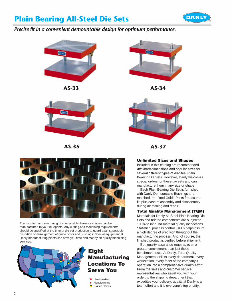
Unlimited Sizes and Shapes Included in this catalog are recommendedminimum dimensions and popular sizes forseveral different types of All-Steel PlainBearing Die Sets. However, Danly welcomesspecial orders for these die sets and canmanufacture them in any size or shape.
Each Plain Bearing Die Set is furnishedwith Danly Demountable Bushings andmatched, pre-fitted Guide Posts for accuratefit, plus ease of assembly and disassemblyduring diemaking and repair.
Total Quality Management (TQM)Materials for Danly All-Steel Plain Bearing DieSets and related components are subjected100% to inbound material quality inspections.Statistical process control (SPC) helps assurea high degree of precision throughout themanufacturing process. And, of course, thefinished product is verified before shipment.
But, quality assurance requires even agreater commitment than just thesebenchmark tests. At Danly, Total QualityManagement enlists every department, everyworkstation, every facet of the company’soperation into a comprehensive quality effort. From the sales and customer servicerepresentatives who assist you with yourorder, to the shipping department thatexpedites your delivery, quality at Danly is ateam effort and it is everyone’s top priority.
Precise fit in a convenient demountable design for optimum performance.
EightManufacturingLocations ToServe You
★
HeadquartersManufacturingBranch Offices
★
Torch cutting and machining of special slots, holes or shapes can bemanufactured to your blueprints. Any cutting and machining requirementsshould be specified at the time of die set production to guard against possibledistortion or misalignment of guide posts and bushings. Special equipment atDanly manufacturing plants can save you time and money on quality machiningservices.
AS-33 AS-34
AS-35 AS-37
Index ®
3
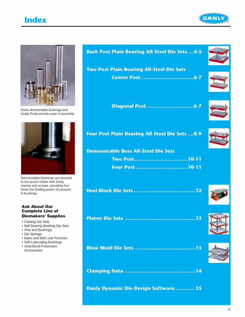
Back Post Plain Bearing All-Steel Die Sets ....4-5
Two Post Plain Bearing All-Steel Die Sets
Center Post...................................6-7
Diagonal Post ...............................6-7
Four Post Plain Bearing All-Steel Die Sets ....8-9
Demountable Boss All-Steel Die Sets
Two Post...................................10-11
Four Post ..................................10-11
Heel Block Die Sets.........................................12
Platen Die Sets ...............................................13
Blow Mold Die Sets ........................................13
Clamping Data ...............................................14
Danly Dynamic Die Design Software..............15
Ask About OurComplete Line ofDiemakers’ Supplies• Catalog Die Sets• Ball Bearing Bushing Die Sets• Pins and Bushings• Die Springs• Basic and Ball Lock Punches• Self Lubricating Bushings• Gold Bond Pressroom
Accessories
Demountable Bushings are securedto the punch holder with Danlyclamps and screws, providing fourtimes the holding power of pressed-in bushings.
Danly demountable Bushings andGuide Posts provide ease of assembly.
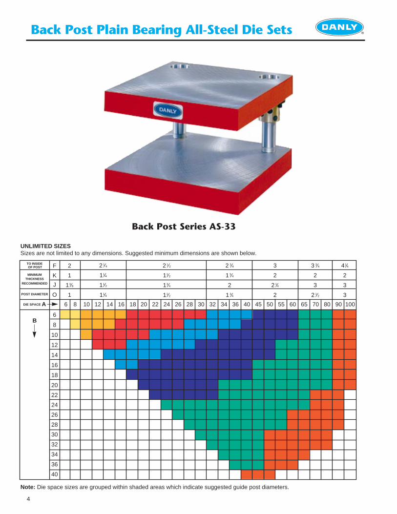
TO INSIDEOF POST
MINIMUM THICKNESS
RECOMMENDED
POST DIAMETER
DIE SPACE A
B
10
Back Post Plain Bearing All-Steel Die Sets ®
4
F
K
J
O
6
8
10
12
14
16
18
20
22
24
26
28
30
32
34
36
40
86 12 14 16 18 20 22 24 26 28 30 32 34 36 40 45 50 55 60 65 70 80 90 100
2
1
13⁄8
1
2 1⁄4
11⁄4
11⁄2
11⁄4
2 1⁄2
11⁄2
13⁄4
11⁄2
2 3⁄4
1 3⁄4
2
1 3⁄4
3
2
2 1⁄4
2
3 3⁄4
2
3
2 1⁄2
41⁄4
2
3
3
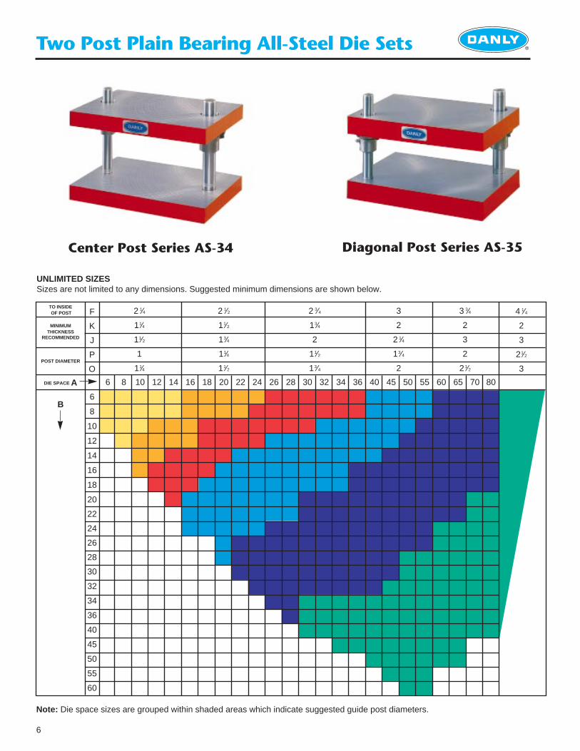
Note: Die space sizes are grouped within shaded areas which indicate suggested guide post diameters.
UNLIMITED SIZESSizes are not limited to any dimensions. Suggested minimum dimensions are shown below.
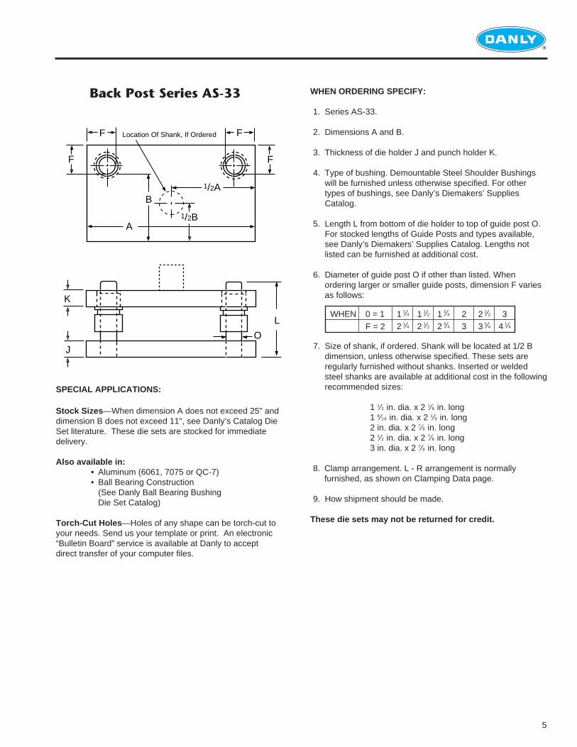
Back Post Series AS-33
®
5
Back Post Series AS-33 WHEN ORDERING SPECIFY:
1. Series AS-33.
2. Dimensions A and B.
3. Thickness of die holder J and punch holder K.
4. Type of bushing. Demountable Steel Shoulder Bushings will be furnished unless otherwise specified. For other types of bushings, see Danly’s Diemakers’ SuppliesCatalog.
5. Length L from bottom of die holder to top of guide post O. For stocked lengths of Guide Posts and types available, see Danly’s Diemakers’ Supplies Catalog. Lengths not listed can be furnished at additional cost.
6. Diameter of guide post O if other than listed. When ordering larger or smaller guide posts, dimension F varies as follows:
7. Size of shank, if ordered. Shank will be located at 1/2 B dimension, unless otherwise specified. These sets are regularly furnished without shanks. Inserted or welded steel shanks are available at additional cost in the followingrecommended sizes:
1 1⁄2 in. dia. x 2 1⁄8 in. long1 9⁄16 in. dia. x 2 1⁄8 in. long2 in. dia. x 2 7⁄8 in. long2 1⁄2 in. dia. x 2 7⁄8 in. long3 in. dia. x 2 7⁄8 in. long
8. Clamp arrangement. L - R arrangement is normallyfurnished, as shown on Clamping Data page.
9. How shipment should be made.
These die sets may not be returned for credit.
F
FF
A
B
1/2B
1/2A
F
O
K
L
J
Location Of Shank, If Ordered
WHEN 0 = 1
F = 2
1 1⁄4
2 1⁄41 1⁄2
2 1⁄21 3⁄4
2 3⁄423
2 1⁄2
3 3⁄43
4 1⁄4
SPECIAL APPLICATIONS:
Stock Sizes —When dimension A does not exceed 25" anddimension B does not exceed 11", see Danly’s Catalog DieSet literature. These die sets are stocked for immediatedelivery.
Also available in: • Aluminum (6061, 7075 or QC-7)• Ball Bearing Construction
(See Danly Ball Bearing Bushing Die Set Catalog)
Torch-Cut Holes —Holes of any shape can be torch-cut toyour needs. Send us your template or print. An electronic“Bulletin Board” service is available at Danly to acceptdirect transfer of your computer files.
6
Two Post Plain Bearing All-Steel Die Sets ®
6
F
K
J
P
O
6
8
10
12
14
16
18
20
22
24
26
28
30
32
34
36
40
45
50
55
60
8 10 12 14 16 18 20 22 24 26 28 30 32 34 36 40 45 50 55 60 65 70 80
4 1⁄4
2
3
21⁄2
3
2 1⁄4
11⁄4
11⁄2
1
11⁄4
2 1⁄2
11⁄2
13⁄4
11⁄4
11⁄2
2 3⁄4
13⁄4
2
11⁄2
13⁄4
3
2
2 1⁄4
13⁄4
2
3 3⁄4
2
3
2
21⁄2
Note: Die space sizes are grouped within shaded areas which indicate suggested guide post diameters.
Center Post Series AS-34 Diagonal Post Series AS-35
UNLIMITED SIZESSizes are not limited to any dimensions. Suggested minimum dimensions are shown below.
TO INSIDEOF POST
MINIMUM THICKNESS
RECOMMENDED
POST DIAMETER
DIE SPACE A
B
®
7
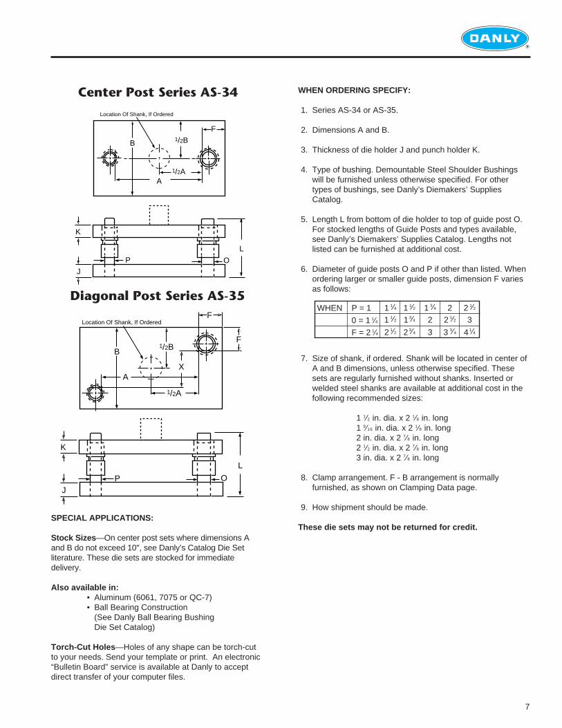
Center Post Series AS-34
Diagonal Post Series AS-35
F
A
B
1/2A
O
K
L
J
Location Of Shank, If Ordered
1/2B
P
O
K
L
J
F
F
A
1/2B
X
1/2A
B
P
Location Of Shank, If Ordered
WHEN ORDERING SPECIFY:
1. Series AS-34 or AS-35.
2. Dimensions A and B.
3. Thickness of die holder J and punch holder K.
4. Type of bushing. Demountable Steel Shoulder Bushings will be furnished unless otherwise specified. For other types of bushings, see Danly’s Diemakers’ SuppliesCatalog.
5. Length L from bottom of die holder to top of guide post O. For stocked lengths of Guide Posts and types available, see Danly’s Diemakers’ Supplies Catalog. Lengths not listed can be furnished at additional cost.
6. Diameter of guide posts O and P if other than listed. When ordering larger or smaller guide posts, dimension F varies as follows:
7. Size of shank, if ordered. Shank will be located in center of A and B dimensions, unless otherwise specified. These sets are regularly furnished without shanks. Inserted or welded steel shanks are available at additional cost in thefollowing recommended sizes:
1 1⁄2 in. dia. x 2 1⁄8 in. long1 9⁄16 in. dia. x 2 1⁄8 in. long2 in. dia. x 2 7⁄8 in. long2 1⁄2 in. dia. x 2 7⁄8 in. long3 in. dia. x 2 7⁄8 in. long
8. Clamp arrangement. F - B arrangement is normallyfurnished, as shown on Clamping Data page.
9. How shipment should be made.
These die sets may not be returned for credit.SPECIAL APPLICATIONS:
Stock Sizes —On center post sets where dimensions Aand B do not exceed 10", see Danly’s Catalog Die Setliterature. These die sets are stocked for immediatedelivery.
Also available in:• Aluminum (6061, 7075 or QC-7)• Ball Bearing Construction
(See Danly Ball Bearing Bushing Die Set Catalog)
Torch-Cut Holes —Holes of any shape can be torch-cutto your needs. Send your template or print. An electronic“Bulletin Board” service is available at Danly to acceptdirect transfer of your computer files.
WHEN P = 1
0 = 1 1⁄4
F = 2 1⁄4
1 1⁄4
1 1⁄2
2 1⁄2
22 1⁄2
3 3⁄4
2 1⁄2
3
4 1⁄4
1 1⁄2
1 3⁄4
2 3⁄4
1 3⁄4
2
3
Four Post Plain Bearing All-Steel Die Sets ®
8
F
K
J
O
6
8
10
12
14
16
18
20
22
24
26
28
30
32
34
36
40
45
50
55
60
86 10 12 14 16 18 20 22 24 26 28 30 32 34 36 40 45 50 55 60 65 70 80 90 100
2
1
1 3⁄8
1
2 1⁄4
1 1⁄4
1 1⁄2
1 1⁄4
2 1⁄2
1 1⁄2
1 3⁄4
1 1⁄2
2 3⁄4
1 3⁄4
2
1 3⁄4
3
2
21⁄4
2
3 3⁄4
2
3
2 1⁄2
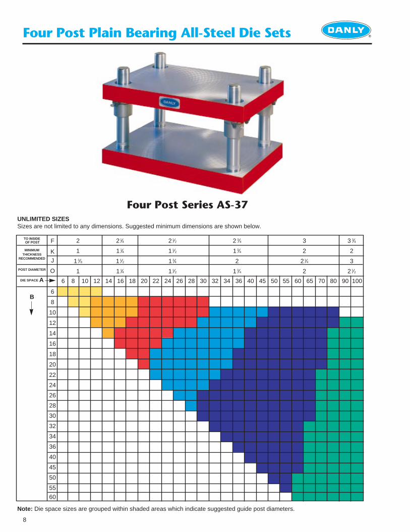
Note: Die space sizes are grouped within shaded areas which indicate suggested guide post diameters.
UNLIMITED SIZESSizes are not limited to any dimensions. Suggested minimum dimensions are shown below.
Four Post Series AS-37
TO INSIDEOF POST
MINIMUM THICKNESS
RECOMMENDED
POST DIAMETER
DIE SPACE A
B
®
9
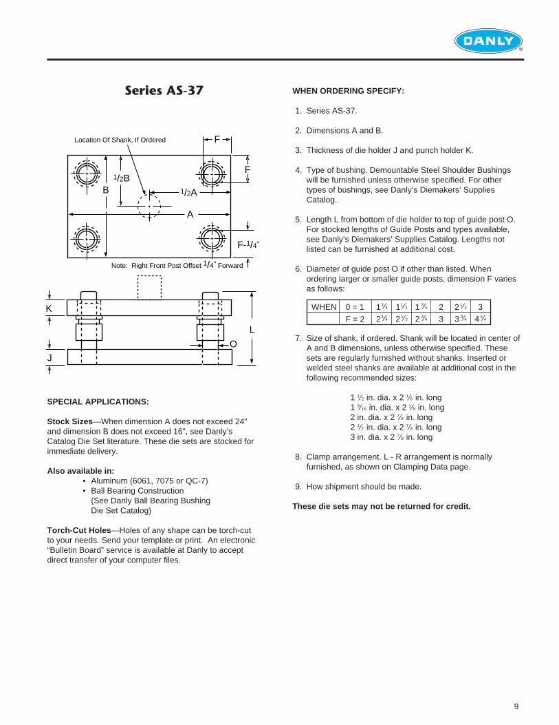
WHEN ORDERING SPECIFY:
1. Series AS-37.
2. Dimensions A and B.
3. Thickness of die holder J and punch holder K.
4. Type of bushing. Demountable Steel Shoulder Bushings will be furnished unless otherwise specified. For other types of bushings, see Danly’s Diemakers’ SuppliesCatalog.
5. Length L from bottom of die holder to top of guide post O. For stocked lengths of Guide Posts and types available, see Danly’s Diemakers’ Supplies Catalog. Lengths not listed can be furnished at additional cost.
6. Diameter of guide post O if other than listed. When ordering larger or smaller guide posts, dimension F variesas follows:
7. Size of shank, if ordered. Shank will be located in center of A and B dimensions, unless otherwise specified. These sets are regularly furnished without shanks. Inserted or welded steel shanks are available at additional cost in thefollowing recommended sizes:
1 1⁄2 in. dia. x 2 1⁄8 in. long1 9⁄16 in. dia. x 2 1⁄8 in. long2 in. dia. x 2 7⁄8 in. long2 1⁄2 in. dia. x 2 7⁄8 in. long3 in. dia. x 2 7⁄8 in. long
8. Clamp arrangement. L - R arrangement is normallyfurnished, as shown on Clamping Data page.
9. How shipment should be made.
These die sets may not be returned for credit.
Series AS-37
A
1/2AB1/2B
F
F
F-1/4"
O
K
L
J
Location Of Shank, If Ordered
Note: Right Front Post Offset 1/4" Forward
SPECIAL APPLICATIONS:
Stock Sizes —When dimension A does not exceed 24"and dimension B does not exceed 16", see Danly’sCatalog Die Set literature. These die sets are stocked forimmediate delivery.
Also available in:• Aluminum (6061, 7075 or QC-7)• Ball Bearing Construction
(See Danly Ball Bearing Bushing Die Set Catalog)
Torch-Cut Holes —Holes of any shape can be torch-cutto your needs. Send your template or print. An electronic“Bulletin Board” service is available at Danly to acceptdirect transfer of your computer files.
WHEN 0 = 1
F = 2
1 1⁄4
2 1⁄411⁄2
2 1⁄21 3⁄4
2 3⁄423
2 1⁄2
3 3⁄43
4 1⁄4
®
10
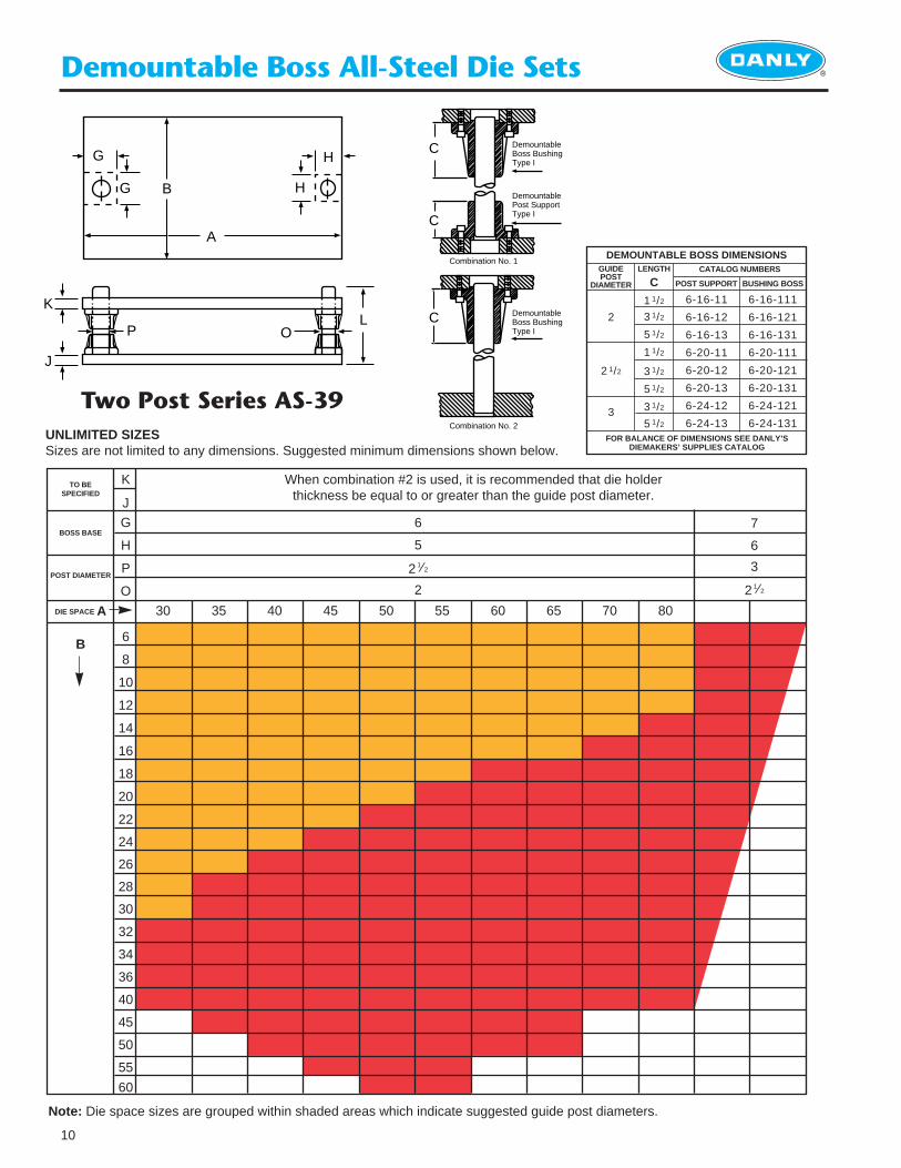
Demountable Boss All-Steel Die Sets
K
J
G
H
P
O
6
8
10
12
14
16
18
20
22
24
26
28
30
32
34
36
40
45
50
55
60
30 35 40 45 50 55 60 65 70 80
6
5
2 1⁄2
2
7
6
3
2 1⁄2
Note: Die space sizes are grouped within shaded areas which indicate suggested guide post diameters.
UNLIMITED SIZESSizes are not limited to any dimensions. Suggested minimum dimensions shown below.
Two Post Series AS-39
When combination #2 is used, it is recommended that die holderthickness be equal to or greater than the guide post diameter.
TO BESPECIFIED
BOSS BASE
POST DIAMETER
DIE SPACE A
B
DemountableBoss BushingType I
C
DemountablePost Support Type I
Combination No. 1
Combination No. 2
DemountableBoss BushingType I
C
C
DEMOUNTABLE BOSS DIMENSIONS
FOR BALANCE OF DIMENSIONS SEE DANLY’S DIEMAKERS’ SUPPLIES CATALOG
GUIDE POST
DIAMETER
LENGTH
CCATALOG NUMBERS
POST SUPPORT BUSHING BOSS
2
2 1/2
3
1 1/2
3 1/2
5 1/2
1 1/2
3 1/2
5 1/2
3 1/2
5 1/2
6-16-11
6-16-12
6-16-13
6-20-11
6-20-12
6-20-13
6-24-12
6-24-13
6-16-111
6-16-121
6-16-131
6-20-111
6-20-121
6-20-131
6-24-121
6-24-131
G
G H
H
A
B
K
J
P OL
®
11
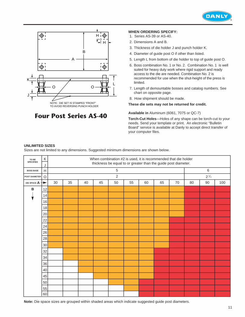
Four Post Series AS-40
K
J
H
O
12
14
16
18
20
22
24
26
28
30
32
34
36
40
45
50
55
60
30 35 40 45 50
5 6
2 2 1⁄2
55 60 65 70 80 90 100
When combination #2 is used, it is recommended that die holderthickness be equal to or greater than the guide post diameter.
Note: Die space sizes are grouped within shaded areas which indicate suggested guide post diameters.
UNLIMITED SIZESSizes are not limited to any dimensions. Suggested minimum dimensions are shown below.
TO BESPECIFIED
BOSS BASE
POST DIAMETER
DIE SPACE A
B
WHEN ORDERING SPECIFY:1. Series AS-39 or AS-40.
2. Dimensions A and B.
3. Thickness of die holder J and punch holder K.
4. Diameter of guide post O if other than listed.
5. Length L from bottom of die holder to top of guide post O.
6. Boss combination No. 1 or No. 2. Combination No. 1 is wellsuited for heavy duty work where rigid support and readyaccess to the die are needed. Combination No. 2 isrecommended for use when the shut-height of the press islimited.
7. Length of demountable bosses and catalog numbers. Seechart on opposite page.
8. How shipment should be made.
These die sets may not be returned for credit.
Available in Aluminum (6061, 7075 or QC-7)
Torch-Cut Holes —Holes of any shape can be torch-cut to yourneeds. Send your template or print. An electronic “BulletinBoard” service is available at Danly to accept direct transfer ofyour computer files.
A
B
H
H
OO
K
J
L
NOTE: DIE SET IS STAMPED "FRONT"TO AVOID REVERSING PUNCH HOLDER
®
12
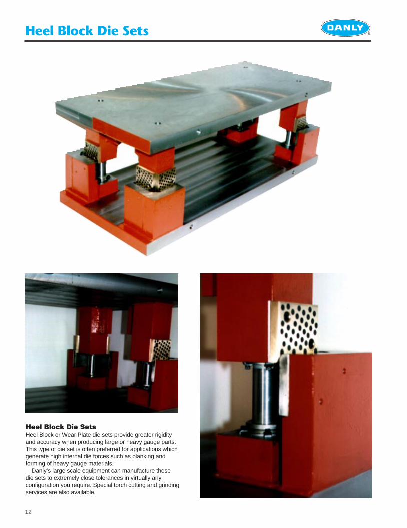
Heel Block Die Sets
Heel Block Die SetsHeel Block or Wear Plate die sets provide greater rigidityand accuracy when producing large or heavy gauge parts.This type of die set is often preferred for applications whichgenerate high internal die forces such as blanking andforming of heavy gauge materials.
Danly’s large scale equipment can manufacture thesedie sets to extremely close tolerances in virtually anyconfiguration you require. Special torch cutting and grindingservices are also available.
®
13
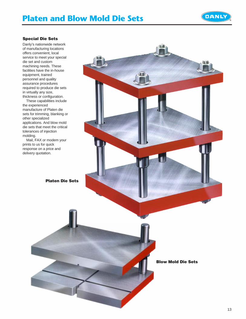
Platen and Blow Mold Die Sets
Platen Die Sets
Blow Mold Die Sets
Special Die SetsDanly’s nationwide networkof manufacturing locationsoffers convenient, localservice to meet your specialdie set and custommachining needs. Thesefacilities have the in-houseequipment, trainedpersonnel and qualityassurance proceduresrequired to produce die setsin virtually any size,thickness or configuration.
These capabilities includethe experiencedmanufacture of Platen diesets for trimming, blanking orother specializedapplications. And blow molddie sets that meet the criticaltolerances of injectionmolding.
Mail, FAX or modem yourprints to us for quickresponse on a price anddelivery quotation.
®
14
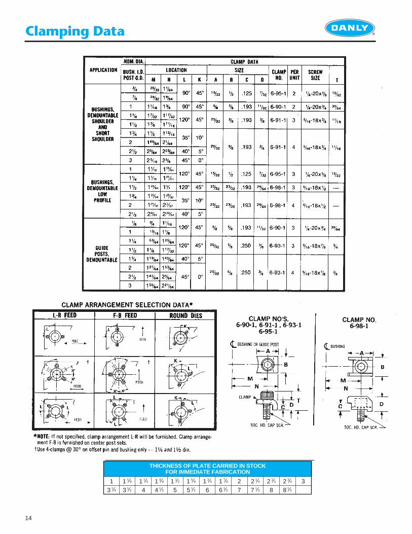
Clamping Data
THICKNESS OF PLATE CARRIED IN STOCKFOR IMMEDIATE FABRICATION
13 1⁄4
1 1⁄8
3 1⁄21 1⁄4
41 3⁄8
4 1⁄21 1⁄2
51 5⁄8
5 1⁄21 3⁄4
61 7⁄8
6 1⁄227
2 1⁄4
7 1⁄22 1⁄2
82 3⁄4
8 1⁄23
®
15
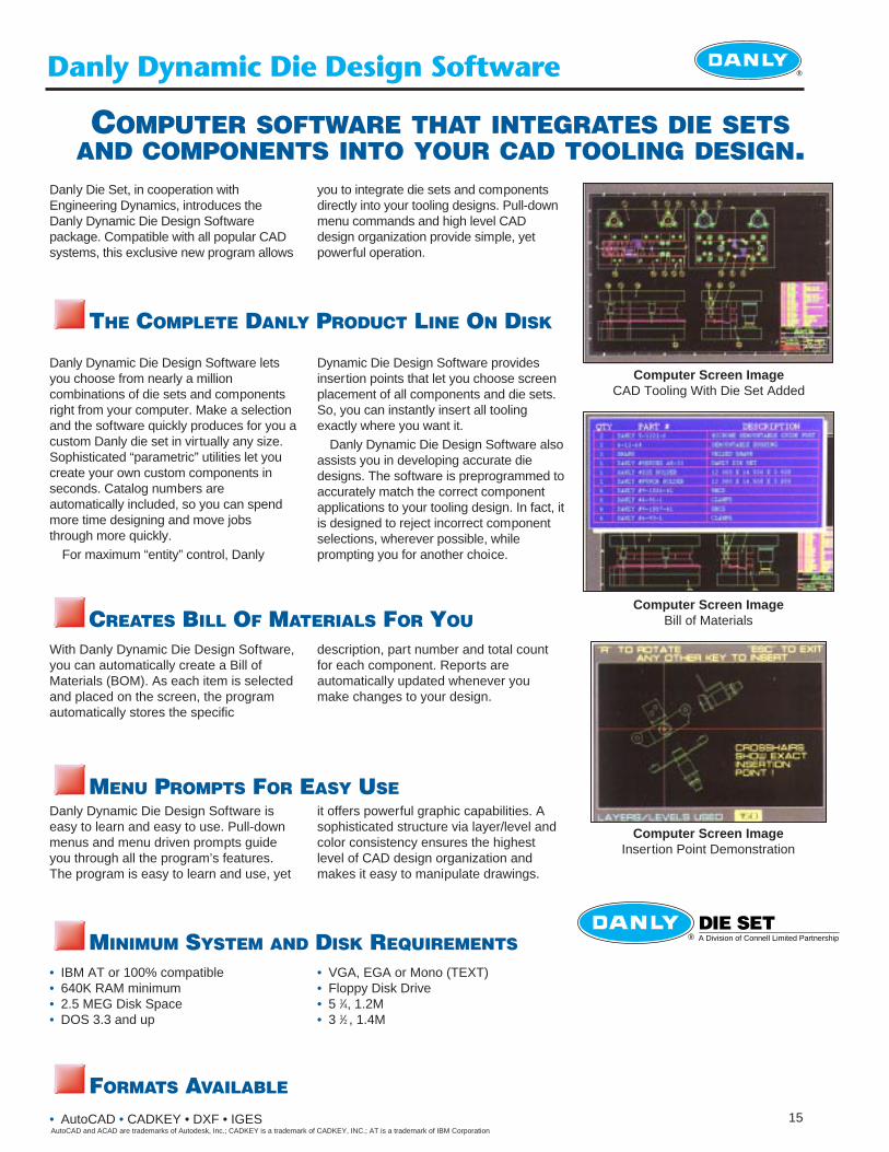
Danly Dynamic Die Design Software
COMPUTER SOFTWARE THAT INTEGRATES DIE SETSAND COMPONENTS INTO YOUR CAD TOOLING DESIGN.
A Division of Connell Limited Partnership
DIE SET®
Computer Screen ImageCAD Tooling With Die Set Added
Computer Screen ImageBill of Materials
Computer Screen ImageInsertion Point Demonstration
Danly Dynamic Die Design Software letsyou choose from nearly a millioncombinations of die sets and componentsright from your computer. Make a selectionand the software quickly produces for you acustom Danly die set in virtually any size.Sophisticated “parametric” utilities let youcreate your own custom components inseconds. Catalog numbers areautomatically included, so you can spendmore time designing and move jobsthrough more quickly.
For maximum “entity” control, Danly
Danly Die Set, in cooperation withEngineering Dynamics, introduces theDanly Dynamic Die Design Softwarepackage. Compatible with all popular CADsystems, this exclusive new program allows
you to integrate die sets and componentsdirectly into your tooling designs. Pull-downmenu commands and high level CADdesign organization provide simple, yetpowerful operation.
Dynamic Die Design Software providesinsertion points that let you choose screenplacement of all components and die sets.So, you can instantly insert all toolingexactly where you want it.
Danly Dynamic Die Design Software alsoassists you in developing accurate diedesigns. The software is preprogrammed toaccurately match the correct componentapplications to your tooling design. In fact, itis designed to reject incorrect componentselections, wherever possible, whileprompting you for another choice.
With Danly Dynamic Die Design Software,you can automatically create a Bill ofMaterials (BOM). As each item is selectedand placed on the screen, the programautomatically stores the specific
description, part number and total countfor each component. Reports areautomatically updated whenever youmake changes to your design.
Danly Dynamic Die Design Software iseasy to learn and easy to use. Pull-downmenus and menu driven prompts guideyou through all the program’s features.The program is easy to learn and use, yet
it offers powerful graphic capabilities. Asophisticated structure via layer/level andcolor consistency ensures the highestlevel of CAD design organization andmakes it easy to manipulate drawings.
• VGA, EGA or Mono (TEXT)• Floppy Disk Drive• 5 1⁄4, 1.2M • 3 1⁄2 , 1.4M
• IBM AT or 100% compatible• 640K RAM minimum• 2.5 MEG Disk Space• DOS 3.3 and up
• AutoCAD • CADKEY • DXF • IGES
THE COMPLETE DANLY PRODUCT LINE ON DISK
CREATES BILL OF MATERIALS FOR YOU
MENU PROMPTS FOR EASY USE
MINIMUM SYSTEM AND DISK REQUIREMENTS
FORMATS AVAILABLE
AutoCAD and ACAD are trademarks of Autodesk, Inc.; CADKEY is a trademark of CADKEY, INC.; AT is a trademark of IBM Corporation
© 1998 Danly Die SetA Division of Connell Limited PartnershipAll Rights Reserved
DS 104 10M 5/98 HB
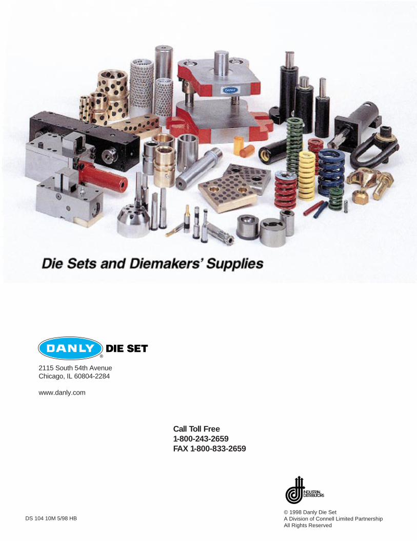
DIE SET®
2115 South 54th AvenueChicago, IL 60804-2284
www.danly.com
Call Toll Free1-800-243-2659FAX 1-800-833-2659