danly iem - plain bearing bushing die sets · plain bearing bushing die sets service we deliver and...
TRANSCRIPT
www.danly.com
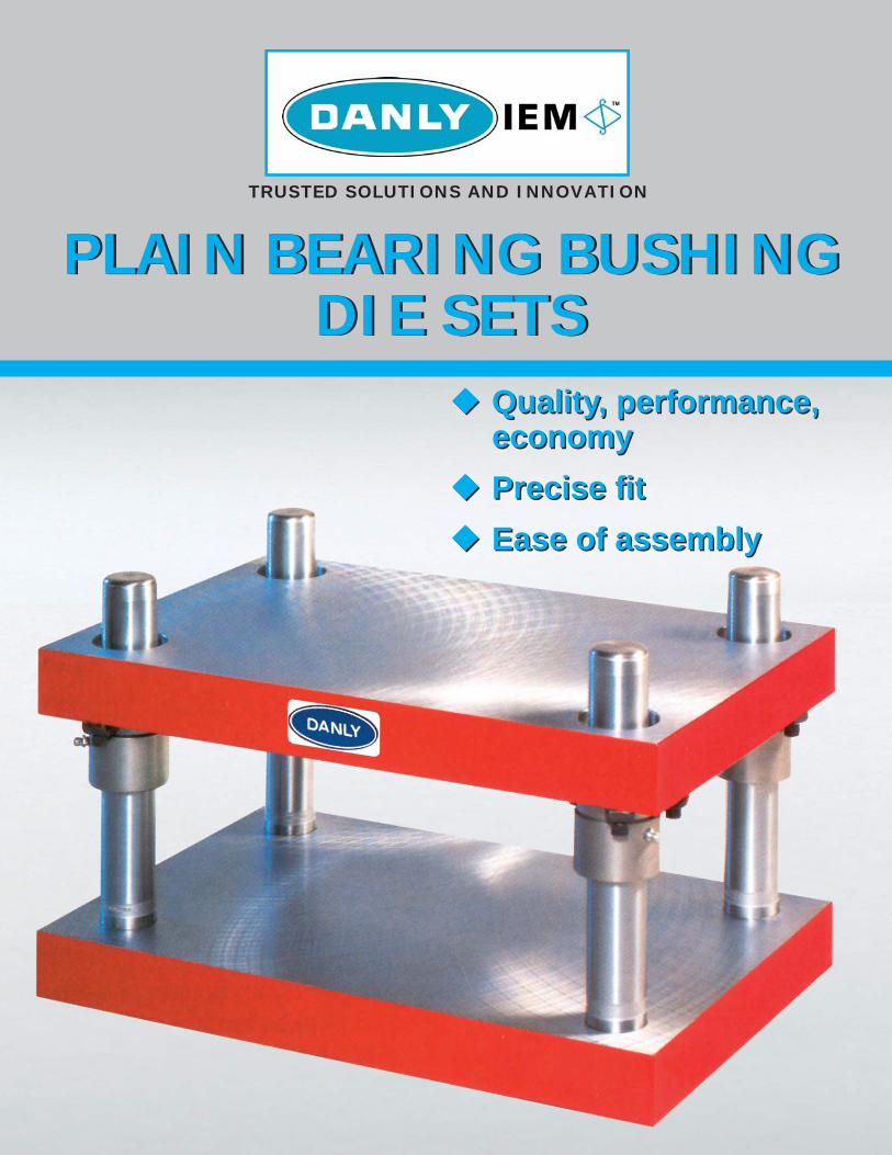
Quality, performance, economyPrecise fi tEase of assembly
PLAIN BEARING BUSHINGDIE SETS
PLAIN BEARING BUSHINGDIE SETS
TRUSTED SOLUTIONS AND INNOVATION
Quality, performance, economyPrecise fi tEase of assembly
www.danly.com
PLAIN BEARING BUSHINGDIE SETS
Service We Deliver and Quality You Can Depend OnDANLY IEM is a leading manufacturer of die sets and die component products supplied globally to the parts forming industry. Backed by years of tool and die experience, quality and innovation are some of the reasons why our name is respected throughout the world. We have taken the lead role in creating and bringing new products to customers and helping them fi nd solutions that improve their operations. Based on the capabilities DANLY IEM offers, we can help you to meet the demands of quick deliveries, technical support, quality products and competitive prices. DANLY IEM and its’ broad distribution channels and direct sales personnel will assist you in any way to make your product a better and more profi table one.
We understand the demanding schedules of die builders and production personnel and have developed effi cient manufacturing processes to shorten product lead times as well as put inventory on our shelves so you can have it in your facility when you need it. Put the DANLY IEM network to work for you. We’ve got the service you’ve been looking for.
Included in our full line offering are both inch and metric size die sets and die components that are designed to numerous die standards including ISO, NAAMS, JIS and many large automotive and appliance manufacturers’ standards. The complete product offering includes:
• Ball bearing and friction style die sets including custom and catalog sets• Machined plate• Guide posts & bushings• ISO and JIS Die springs• In-die tapping units for both mechanical and hydraulic presses• Formathane® Urethane springs, strippers, sheets, bars, rods and die cover fi lm• Diemakers’ supplies such as pry bars, dowel pins, hoist rings, clamps and fasteners• Standard and self-lubricating wear product including wear plate, wear strips, gibs,
keeper plates and guide blocks• Cam units, including MiniTM, Aerial and Die Mount styles• Accu-BendTM Rotary Benders• Standard and Ball lock punches and retainers• Air presses• Pad retainers
1
Back Post Plain Bearing Die Sets 2
Two Post Plain Bearing Die Sets 4
Four Post Plain Bearing Die Sets 6
Demountable Boss Die Sets 8
Heel Block Die Sets 10
Platen Die Sets 11
Blow Mold Die Sets 11
Clamping Data 12
Hoist Rings 14
Die Lubrication 16
Plain Bearing Die Sets
TABLE OF CONTENTS PAGE NUMBER
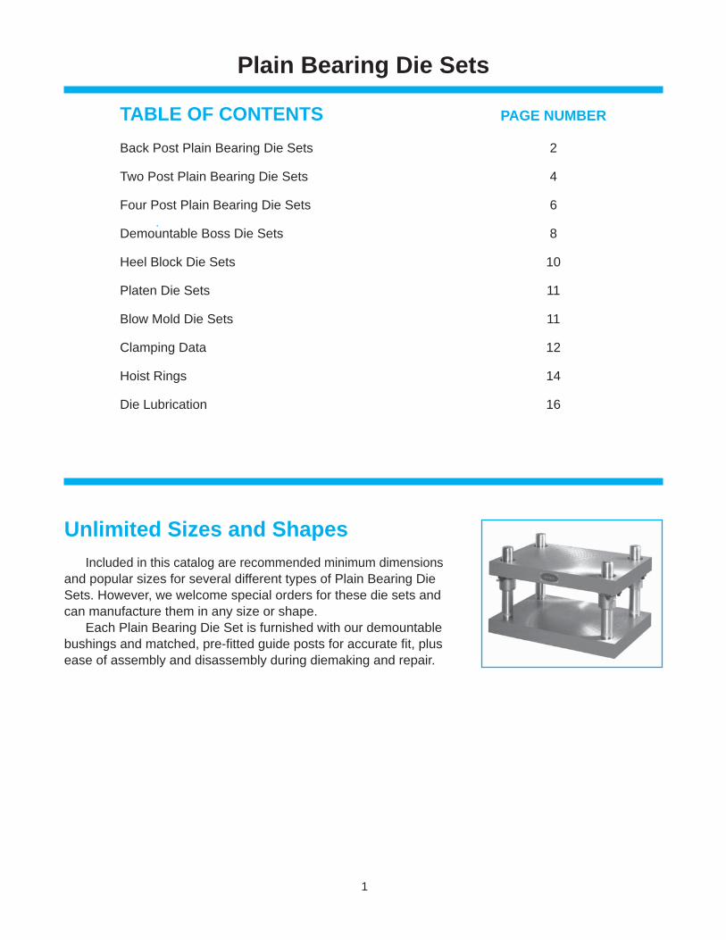
Included in this catalog are recommended minimum dimensions and popular sizes for several different types of Plain Bearing Die Sets. However, we welcome special orders for these die sets and can manufacture them in any size or shape. Each Plain Bearing Die Set is furnished with our demountable bushings and matched, pre-fi tted guide posts for accurate fi t, plus ease of assembly and disassembly during diemaking and repair.
Unlimited Sizes and Shapes
2
Back PostPlain Bearing Die Sets
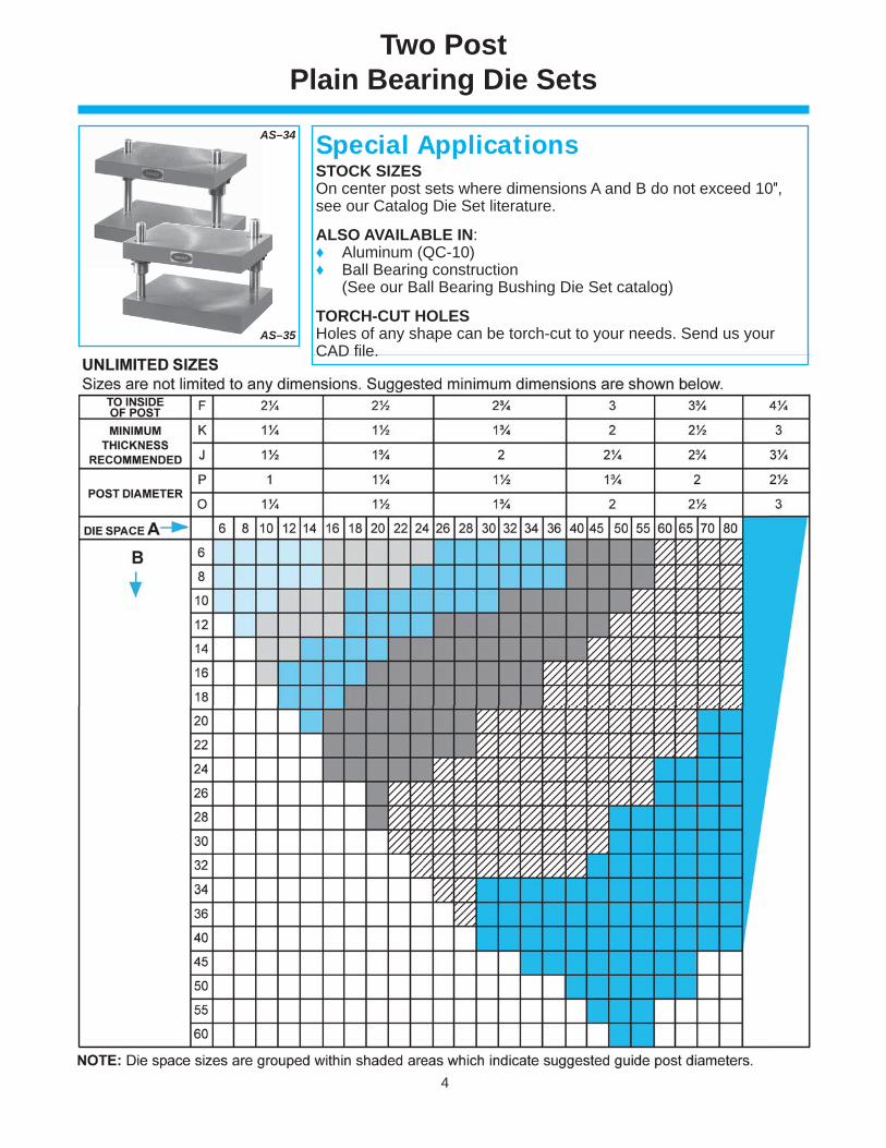
AS–33
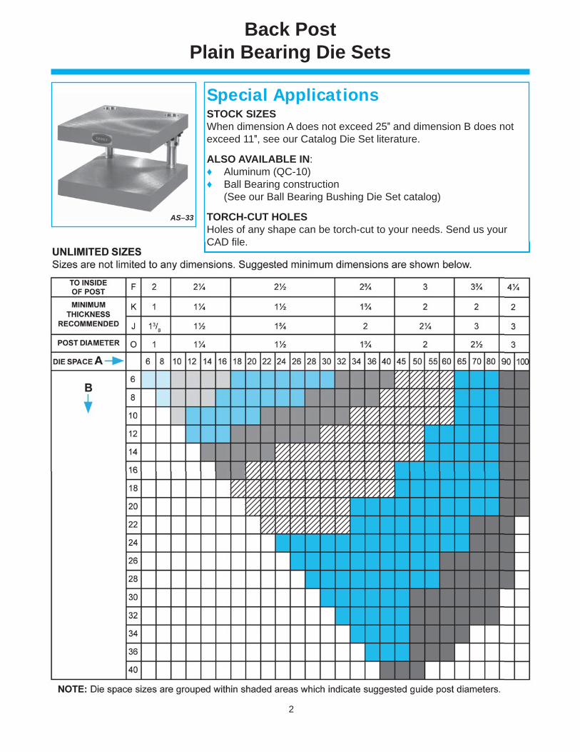
STOCK SIZESWhen dimension A does not exceed 25″ and dimension B does not exceed 11″, see our Catalog Die Set literature.
ALSO AVAILABLE IN:♦ Aluminum (QC-10)♦ Ball Bearing construction (See our Ball Bearing Bushing Die Set catalog)
TORCH-CUT HOLES Holes of any shape can be torch-cut to your needs. Send us your CAD fi le.
Special Applications
CAD fi le.
3
Back PostPlain Bearing Die Sets
F
F
F
F
A
B
1/2B
Location Of Shank, If Ordered
O
K
J
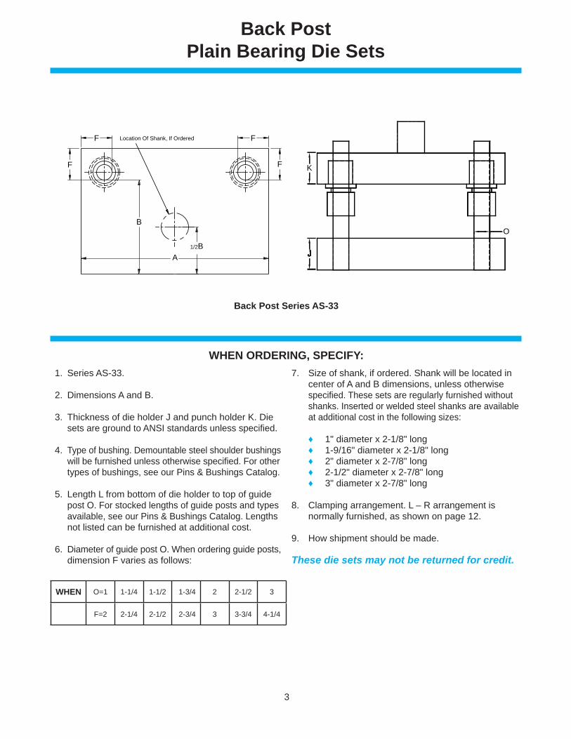
Back Post Series AS-33
WHEN ORDERING, SPECIFY: 1. Series AS-33.
2. Dimensions A and B.
3. Thickness of die holder J and punch holder K. Die sets are ground to ANSI standards unless specifi ed.
4. Type of bushing. Demountable steel shoulder bushings will be furnished unless otherwise specifi ed. For other types of bushings, see our Pins & Bushings Catalog.
5. Length L from bottom of die holder to top of guide post O. For stocked lengths of guide posts and types available, see our Pins & Bushings Catalog. Lengths not listed can be furnished at additional cost.
6. Diameter of guide post O. When ordering guide posts, dimension F varies as follows:
7. Size of shank, if ordered. Shank will be located in center of A and B dimensions, unless otherwise specifi ed. These sets are regularly furnished without shanks. Inserted or welded steel shanks are available at additional cost in the following sizes:
♦ 1" diameter x 2-1/8" long ♦ 1-9/16" diameter x 2-1/8" long ♦ 2" diameter x 2-7/8" long ♦ 2-1/2" diameter x 2-7/8" long ♦ 3" diameter x 2-7/8" long
8. Clamping arrangement. L – R arrangement is normally furnished, as shown on page 12.
9. How shipment should be made.
These die sets may not be returned for credit.
WHEN O=1 1-1/4 1-1/2 1-3/4 2 2-1/2 3
F=2 2-1/4 2-1/2 2-3/4 3 3-3/4 4-1/4
4
Two PostPlain Bearing Die Sets
AS–35
STOCK SIZESOn center post sets where dimensions A and B do not exceed 10″, see our Catalog Die Set literature.
ALSO AVAILABLE IN:♦ Aluminum (QC-10)♦ Ball Bearing construction (See our Ball Bearing Bushing Die Set catalog)
TORCH-CUT HOLES Holes of any shape can be torch-cut to your needs. Send us your CAD fi le.
Special ApplicationsAS–34
5
B
K
J
1/2B
F
A
1/2A
OP
Location Of Shank, If Ordered
B
K
J
1/2B
P
F
F
X
1/2A
A
O
Location Of Shank, If Ordered
Two PostPlain Bearing Die Sets
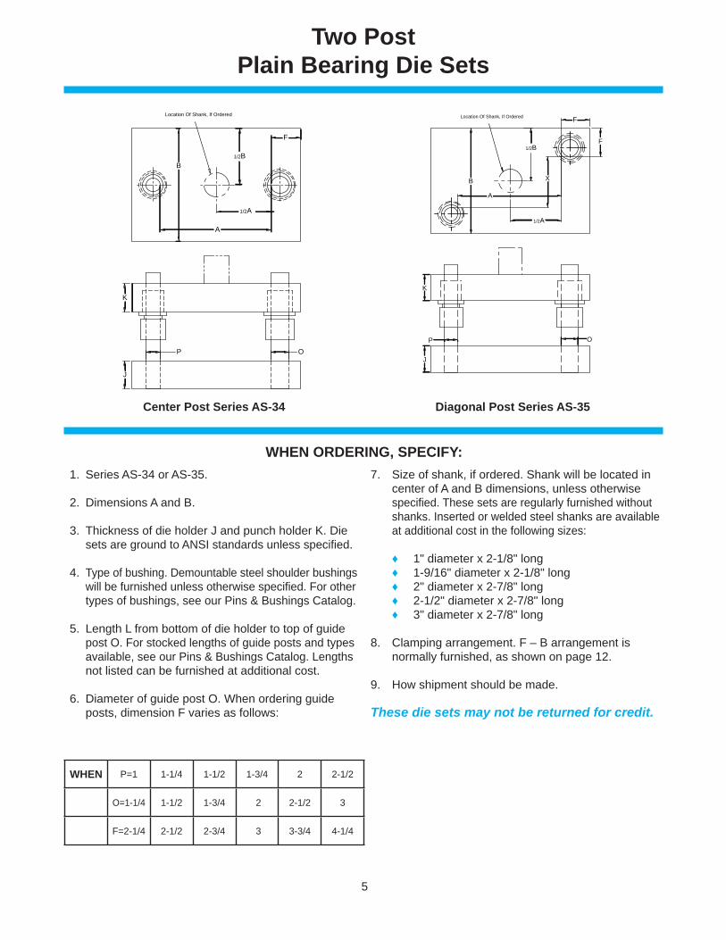
Center Post Series AS-34
WHEN ORDERING, SPECIFY: 1. Series AS-34 or AS-35.
2. Dimensions A and B.
3. Thickness of die holder J and punch holder K. Die sets are ground to ANSI standards unless specifi ed.
4. Type of bushing. Demountable steel shoulder bushings will be furnished unless otherwise specifi ed. For other types of bushings, see our Pins & Bushings Catalog.
5. Length L from bottom of die holder to top of guide post O. For stocked lengths of guide posts and types available, see our Pins & Bushings Catalog. Lengths not listed can be furnished at additional cost.
6. Diameter of guide post O. When ordering guide posts, dimension F varies as follows:
7. Size of shank, if ordered. Shank will be located in center of A and B dimensions, unless otherwise specifi ed. These sets are regularly furnished without shanks. Inserted or welded steel shanks are available at additional cost in the following sizes:
♦ 1" diameter x 2-1/8" long ♦ 1-9/16" diameter x 2-1/8" long ♦ 2" diameter x 2-7/8" long ♦ 2-1/2" diameter x 2-7/8" long ♦ 3" diameter x 2-7/8" long
8. Clamping arrangement. F – B arrangement is normally furnished, as shown on page 12.
9. How shipment should be made.
These die sets may not be returned for credit.
WHEN P=1 1-1/4 1-1/2 1-3/4 2 2-1/2
O=1-1/4 1-1/2 1-3/4 2 2-1/2 3
F=2-1/4 2-1/2 2-3/4 3 3-3/4 4-1/4
Diagonal Post Series AS-35
6
Four PostPlain Bearing Die Sets
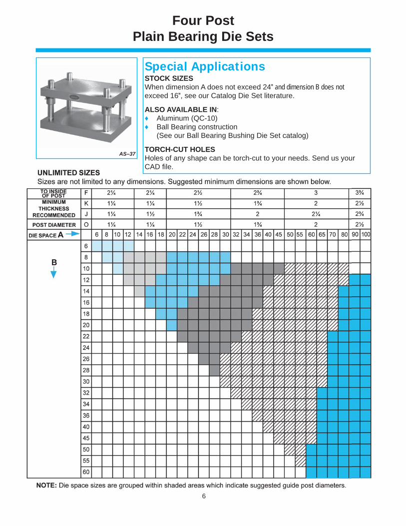
AS–37
STOCK SIZESWhen dimension A does not exceed 24″ and dimension B does not exceed 16″, see our Catalog Die Set literature.
ALSO AVAILABLE IN:♦ Aluminum (QC-10)♦ Ball Bearing construction (See our Ball Bearing Bushing Die Set catalog)
TORCH-CUT HOLES Holes of any shape can be torch-cut to your needs. Send us your CAD fi le.
Special Applications
7
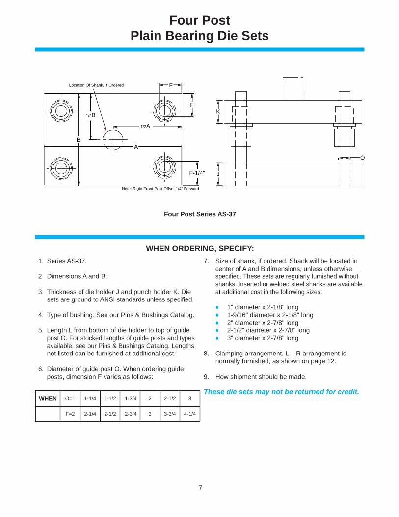
Four PostPlain Bearing Die Sets
B
1/2A
1/2B
F
F
F-1/4"
A
Location Of Shank, If Ordered
Note: Right Front Post Offset 1/4" Forward
Four Post Series AS-37
WHEN ORDERING, SPECIFY: 1. Series AS-37.
2. Dimensions A and B.
3. Thickness of die holder J and punch holder K. Die sets are ground to ANSI standards unless specifi ed.
4. Type of bushing. See our Pins & Bushings Catalog.
5. Length L from bottom of die holder to top of guide post O. For stocked lengths of guide posts and types available, see our Pins & Bushings Catalog. Lengths not listed can be furnished at additional cost.
6. Diameter of guide post O. When ordering guide posts, dimension F varies as follows:
7. Size of shank, if ordered. Shank will be located in center of A and B dimensions, unless otherwise specifi ed. These sets are regularly furnished without shanks. Inserted or welded steel shanks are available at additional cost in the following sizes:
♦ 1" diameter x 2-1/8" long ♦ 1-9/16" diameter x 2-1/8" long ♦ 2" diameter x 2-7/8" long ♦ 2-1/2" diameter x 2-7/8" long ♦ 3" diameter x 2-7/8" long
8. Clamping arrangement. L – R arrangement is normally furnished, as shown on page 12.
9. How shipment should be made.
These die sets may not be returned for credit.WHEN O=1 1-1/4 1-1/2 1-3/4 2 2-1/2 3
F=2 2-1/4 2-1/2 2-3/4 3 3-3/4 4-1/4
O
K
J
8
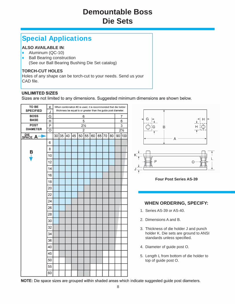
Demountable BossDie Sets
ALSO AVAILABLE IN:♦ Aluminum (QC-10)♦ Ball Bearing construction (See our Ball Bearing Bushing Die Set catalog)
TORCH-CUT HOLES Holes of any shape can be torch-cut to your needs. Send us your CAD fi le.
Special Applications
Four Post Series AS-39
1. Series AS-39 or AS-40.
2. Dimensions A and B.
3. Thickness of die holder J and punch holder K. Die sets are ground to ANSI standards unless specifi ed.
4. Diameter of guide post O.
5. Length L from bottom of die holder to top of guide post O.
WHEN ORDERING, SPECIFY:
9
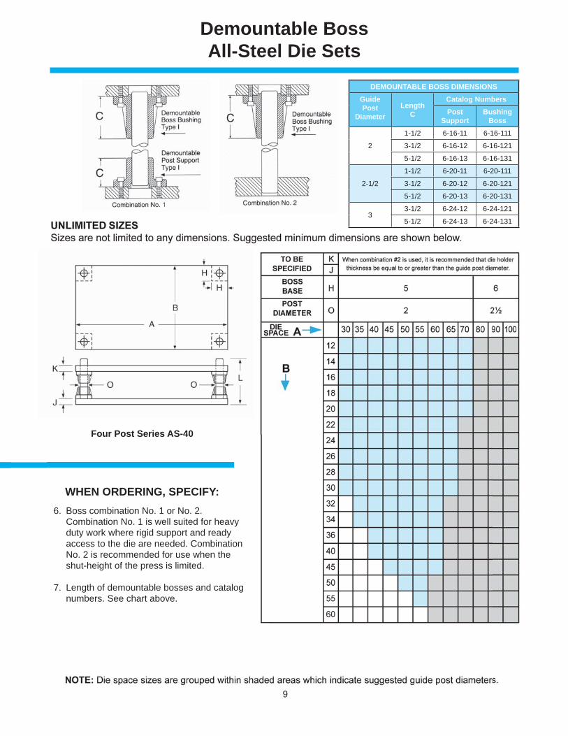
Demountable BossAll-Steel Die Sets
6. Boss combination No. 1 or No. 2. Combination No. 1 is well suited for heavy duty work where rigid support and ready access to the die are needed. Combination No. 2 is recommended for use when the shut-height of the press is limited.
7. Length of demountable bosses and catalog numbers. See chart above.
WHEN ORDERING, SPECIFY:
Four Post Series AS-40
DEMOUNTABLE BOSS DIMENSIONSGuidePost
DiameterLength
C
Catalog NumbersPost
SupportBushing
Boss
2
1-1/2 6-16-11 6-16-111
3-1/2 6-16-12 6-16-121
5-1/2 6-16-13 6-16-131
2-1/2
1-1/2 6-20-11 6-20-111
3-1/2 6-20-12 6-20-121
5-1/2 6-20-13 6-20-131
33-1/2 6-24-12 6-24-121
5-1/2 6-24-13 6-24-131
10
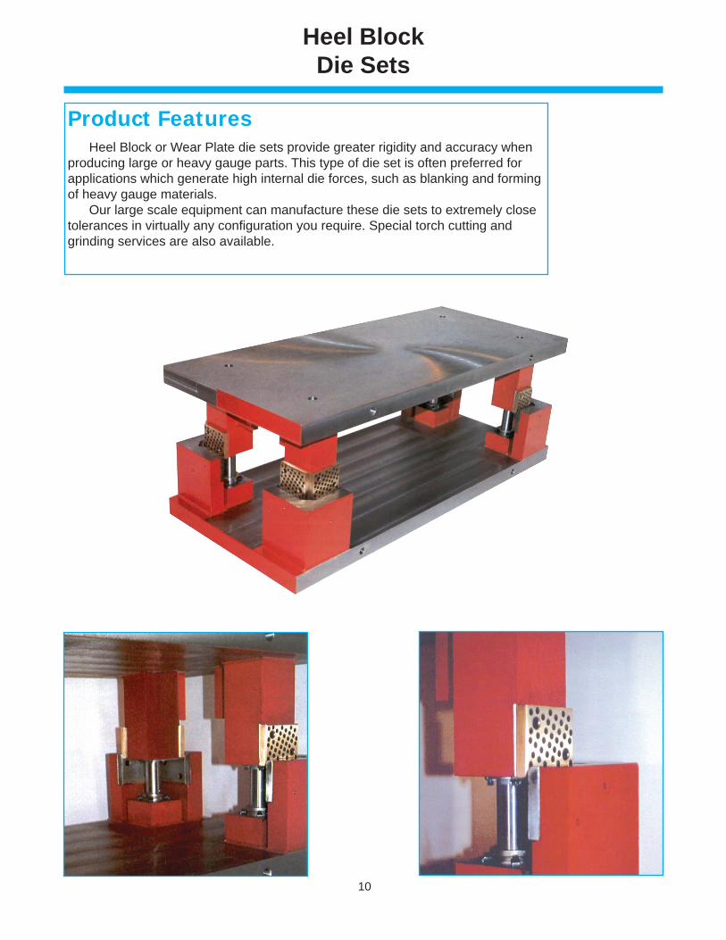
Heel BlockDie Sets
Heel Block or Wear Plate die sets provide greater rigidity and accuracy whenproducing large or heavy gauge parts. This type of die set is often preferred forapplications which generate high internal die forces, such as blanking and formingof heavy gauge materials. Our large scale equipment can manufacture these die sets to extremely closetolerances in virtually any confi guration you require. Special torch cutting andgrinding services are also available.
Product Features
11
Platen and Blow MoldDie Sets
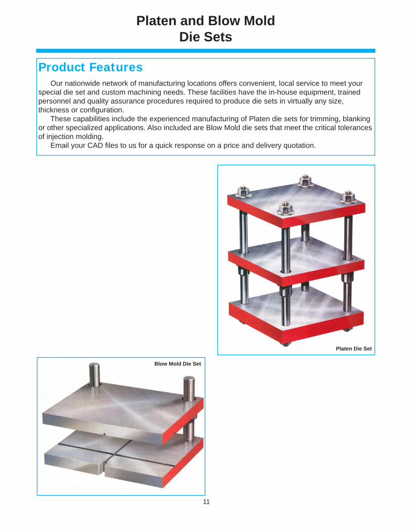
Our nationwide network of manufacturing locations offers convenient, local service to meet yourspecial die set and custom machining needs. These facilities have the in-house equipment, trainedpersonnel and quality assurance procedures required to produce die sets in virtually any size,thickness or confi guration. These capabilities include the experienced manufacturing of Platen die sets for trimming, blanking or other specialized applications. Also included are Blow Mold die sets that meet the critical tolerancesof injection molding. Email your CAD fi les to us for a quick response on a price and delivery quotation.
Product Features
Platen Die Set
Blow Mold Die Set
12
Clamping Data
Nom. Dia.
ClampPart
Number
ScrewPart
Number
Socket HeadCap ScrewDescription
Clamps&
screwsreq’dper
BushingT
(in)
SIZE LOCATION
Bush IDPost OD
A(in)
B(in)
C(in)
D(in)
L M(in)
N (in)
K
3/4 6-95-1 9-0805-41 1/4-20x5/8 long 2 15/32 15/32 1/2 0.125 7/32 90° 25/32 1 1/64 45°
7/8 6-95-1 9-0805-41 1/4-20x5/8 long 2 15/32 15/32 1/2 0.125 7/32 90° 29/32 1 9/64 45°
1 6-90-1 9-0806-41 1/4-20x3/4 long 2 39/64 5/8 5/8 0.193 11/32 90° 1 1/16 1 3/8 45°
1 1/4 6-91-1 9-1006-41 5/16-18x3/4 long 3 11/16 25/32 5/8 0.193 3/8 120° 1 7/32 1 17/32 45°
1 1/2 6-91-1 9-1006-41 5/16-18x3/4 long 3 11/16 25/32 5/8 0.193 3/8 120° 1 3/8 1 11/16 45°
1 3/4 6-91-1 9-1006-41 5/16-18x3/4 long 4 11/16 25/32 5/8 0.193 3/8 35° 1 1/2 1 13/16 10°
2 6-91-1 9-1006-41 5/16-18x3/4 long 4 11/16 25/32 5/8 0.193 3/8 35° 1 45/64 2 1/64 10°
2 1/2 6-91-1 9-1006-41 5/16-18x3/4 long 4 11/16 25/32 5/8 0.193 3/8 40° 2 5/64 2 25/64 5°
3 6-91-1 9-1006-41 5/16-18x3/4 long 4 11/16 25/32 5/8 0.193 3/8 45° 2 5/16 2 5/8 0°
3 3/4 6-91-1 9-1006-41 5/16-18x3/4 long 4 11/16 25/32 5/8 0.193 3/8 45° 2 47/64 2 31/32 0°
4 6-91-1 9-1006-41 5/16-18x3/4 long 4 11/16 25/32 5/8 0.193 3/8 45° 3 11/64 3 13/32 0°
Nom. Dia.
ClampPart
Number
ScrewPart
Number
Socket HeadCap ScrewDescription
Clamps&
screwsreq’dper
BushingT
(in)
SIZE LOCATION
Bush IDPost OD
A(in)
B(in)
C(in)
D(in)
L M(in)
N (in)
K
1 6-95-1 9-0805-41 1/4-20x5/8 long 3 39/64 15/32 1/2 0.125 7/32 120° 1 1/16 1 19/64 45°
1 1/4 6-95-1 9-0805-41 1/4-20x5/8 long 3 11/16 15/32 1/2 0.125 7/32 120° 1 3/16 1 27/64 45°
1 1/2 6-98-1 9-1004-41 5/16-18x1/2 long 3 11/16 23/32 23/32 0.193 29/64 120° 1 29/64 1 3/4 45°
1 3/4 6-98-1 9-1004-41 5/16-18x1/2 long 4 11/16 23/32 23/32 0.193 29/64 35° 1 39/64 1 29/32 10°
2 6-98-1 9-1004-41 5/16-18x1/2 long 4 11/16 23/32 23/32 0.193 29/64 35° 1 25/32 2 3/32 10°
2 1/2 6-98-1 9-1004-41 5/16-18x1/2 long 4 11/16 23/32 23/32 0.193 29/64 40° 2 9/64 2 29/64 5°
Nom. Dia.
ClampPart
Number
ScrewPart
Number
Socket HeadCap ScrewDescription
Clamps&
screwsreq’dper
BushingT
(in)
SIZE LOCATION
Bush IDPost OD
A(in)
B(in)
C(in)
D(in)
L M(in)
N (in)
K
1 6-91-1 9-1006-41 5/16-18x3/4 long 3 11/16 25/32 5/8 0.193 3/8 120° 1 5/16 1 11/16 45°
1 1/4 6-91-1 9-1006-41 5/16-18x3/4 long 3 11/16 25/32 5/8 0.193 3/8 120° 1 7/16 1 13/16 45°
1 1/2 6-91-1 9-1006-41 5/16-18x3/4 long 4 11/16 25/32 5/8 0.193 3/8 120° 1 11/16 2 1/16 45°
1 3/4 6-91-1 9-1006-41 5/16-18x3/4 long 4 11/16 25/32 5/8 0.193 3/8 35° 1 13/16 2 3/16 10°
2 6-91-1 9-1006-41 5/16-18x3/4 long 4 11/16 25/32 5/8 0.193 3/8 35° 2 1/16 2 7/16 10°
2 1/2 6-91-1 9-1006-41 5/16-18x3/4 long 4 11/16 25/32 5/8 0.193 3/8 40° 2 5/16 2 11/16 5°
3 6-91-1 9-1006-41 5/16-18x3/4 long 4 11/16 25/32 5/8 0.193 3/8 45° 2 5/8 3 0°
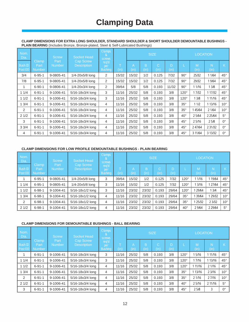
CLAMP DIMENSIONS FOR EXTRA LONG SHOULDER, STANDARD SHOULDER & SHORT SHOULDER DEMOUNTABLE BUSHINGS -PLAIN BEARING (Includes Bronze, Bronze-plated, Steel & Self-Lubricated Bushings)
CLAMP DIMENSIONS FOR LOW PROFILE DEMOUNTABLE BUSHINGS - PLAIN BEARING
CLAMP DIMENSIONS FOR DEMOUNTABLE BUSHINGS - BALL BEARING
13
Clamping Data
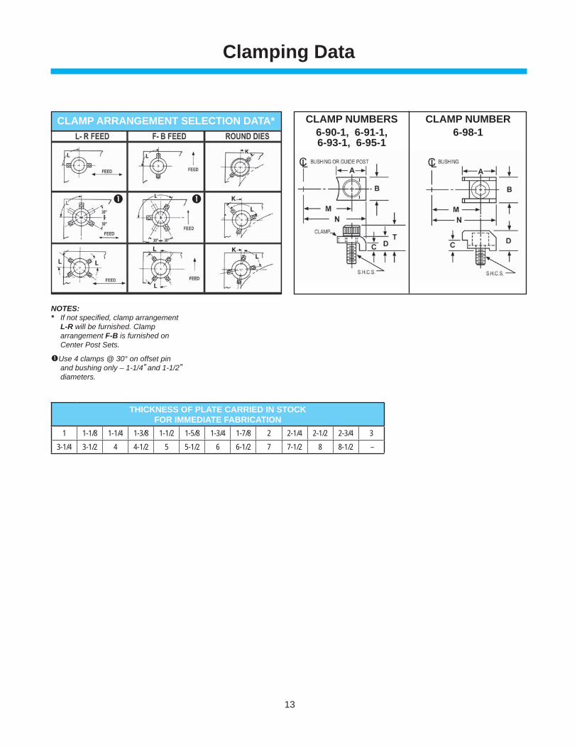
CLAMP NUMBERS6-90-1, 6-91-1,6-93-1, 6-95-1
CLAMP NUMBER6-98-1
THICKNESS OF PLATE CARRIED IN STOCKFOR IMMEDIATE FABRICATION
1 1-1/8 1-1/4 1-3/8 1-1/2 1-5/8 1-3/4 1-7/8 2 2-1/4 2-1/2 2-3/4 33-1/4 3-1/2 4 4-1/2 5 5-1/2 6 6-1/2 7 7-1/2 8 8-1/2 –
NOTES:* If not specifi ed, clamp arrangement
L-R will be furnished. Clamp arrangement F-B is furnished on Center Post Sets.
Use 4 clamps @ 30° on offset pin and bushing only – 1-1/4″ and 1-1/2″ diameters.
CLAMP ARRANGEMENT SELECTION DATA*
14
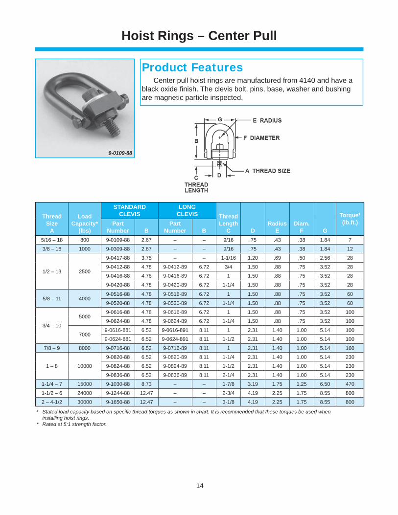
9-0109-88
Center pull hoist rings are manufactured from 4140 and have a black oxide fi nish. The clevis bolt, pins, base, washer and bushing are magnetic particle inspected.
Product Features
ThreadSize
A
LoadCapacity*
(lbs)
STANDARD CLEVIS
LONGCLEVIS Thread
LengthC D
Radius
EDiam.
F G
Torque1
(lb.ft.)Part Number B
Part Number B
5/16 – 18 800 9-0109-88 2.67 – – 9/16 .75 .43 .38 1.84 7
3/8 – 16 1000 9-0309-88 2.67 – – 9/16 .75 .43 .38 1.84 12
1/2 – 13 2500
9-0417-88 3.75 – – 1-1/16 1.20 .69 .50 2.56 28
9-0412-88 4.78 9-0412-89 6.72 3/4 1.50 .88 .75 3.52 28
9-0416-88 4.78 9-0416-89 6.72 1 1.50 .88 .75 3.52 28
9-0420-88 4.78 9-0420-89 6.72 1-1/4 1.50 .88 .75 3.52 28
5/8 – 11 40009-0516-88 4.78 9-0516-89 6.72 1 1.50 .88 .75 3.52 60
9-0520-88 4.78 9-0520-89 6.72 1-1/4 1.50 .88 .75 3.52 60
3/4 – 10
50009-0616-88 4.78 9-0616-89 6.72 1 1.50 .88 .75 3.52 100
9-0624-88 4.78 9-0624-89 6.72 1-1/4 1.50 .88 .75 3.52 100
70009-0616-881 6.52 9-0616-891 8.11 1 2.31 1.40 1.00 5.14 100
9-0624-881 6.52 9-0624-891 8.11 1-1/2 2.31 1.40 1.00 5.14 100
7/8 – 9 8000 9-0716-88 6.52 9-0716-89 8.11 1 2.31 1.40 1.00 5.14 160
1 – 8 10000
9-0820-88 6.52 9-0820-89 8.11 1-1/4 2.31 1.40 1.00 5.14 230
9-0824-88 6.52 9-0824-89 8.11 1-1/2 2.31 1.40 1.00 5.14 230
9-0836-88 6.52 9-0836-89 8.11 2-1/4 2.31 1.40 1.00 5.14 230
1-1/4 – 7 15000 9-1030-88 8.73 – – 1-7/8 3.19 1.75 1.25 6.50 470
1-1/2 – 6 24000 9-1244-88 12.47 – – 2-3/4 4.19 2.25 1.75 8.55 800
2 – 4-1/2 30000 9-1650-88 12.47 – – 3-1/8 4.19 2.25 1.75 8.55 8001 Stated load capacity based on specifi c thread torques as shown in chart. It is recommended that these torques be used when installing hoist rings.* Rated at 5:1 strength factor.
Hoist Rings – Center Pull
15
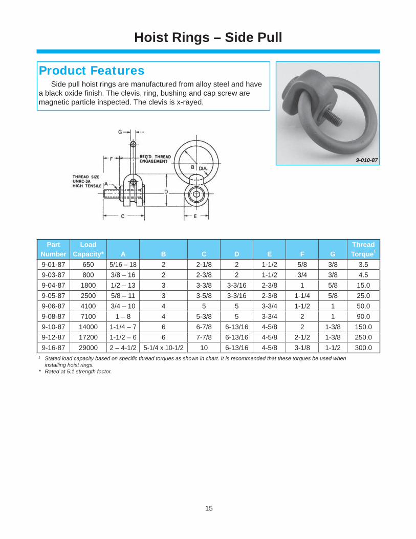
Hoist Rings – Side Pull
9-010-87
Side pull hoist rings are manufactured from alloy steel and have a black oxide fi nish. The clevis, ring, bushing and cap screw are magnetic particle inspected. The clevis is x-rayed.
Product Features
PartNumber
LoadCapacity* A B C D E F G
ThreadTorque1
9-01-87 650 5/16 – 18 2 2-1/8 2 1-1/2 5/8 3/8 3.59-03-87 800 3/8 – 16 2 2-3/8 2 1-1/2 3/4 3/8 4.59-04-87 1800 1/2 – 13 3 3-3/8 3-3/16 2-3/8 1 5/8 15.09-05-87 2500 5/8 – 11 3 3-5/8 3-3/16 2-3/8 1-1/4 5/8 25.09-06-87 4100 3/4 – 10 4 5 5 3-3/4 1-1/2 1 50.09-08-87 7100 1 – 8 4 5-3/8 5 3-3/4 2 1 90.09-10-87 14000 1-1/4 – 7 6 6-7/8 6-13/16 4-5/8 2 1-3/8 150.09-12-87 17200 1-1/2 – 6 6 7-7/8 6-13/16 4-5/8 2-1/2 1-3/8 250.09-16-87 29000 2 – 4-1/2 5-1/4 x 10-1/2 10 6-13/16 4-5/8 3-1/8 1-1/2 300.0
1 Stated load capacity based on specifi c thread torques as shown in chart. It is recommended that these torques be used when installing hoist rings.* Rated at 5:1 strength factor.
16
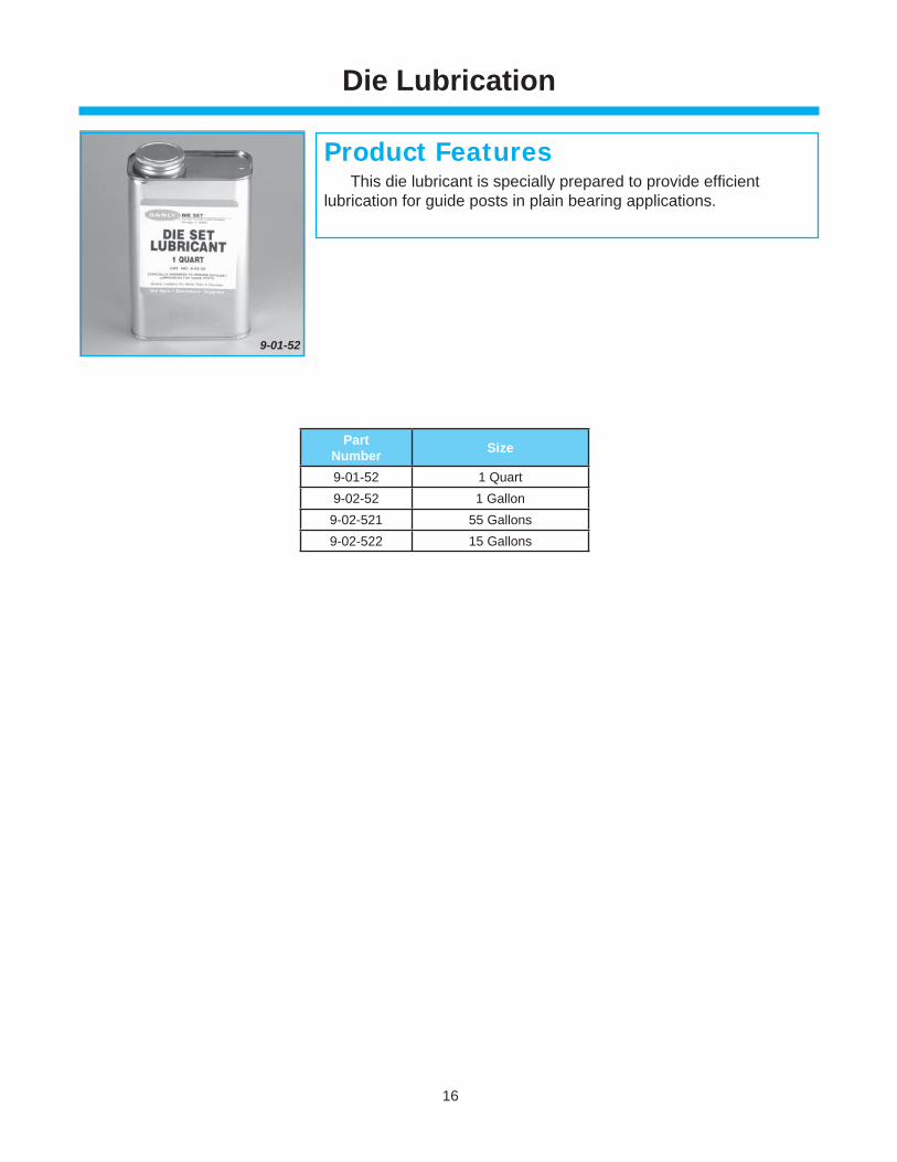
9-01-52
This die lubricant is specially prepared to provide effi cientlubrication for guide posts in plain bearing applications.
Product Features
PartNumber Size
9-01-52 1 Quart9-02-52 1 Gallon9-02-521 55 Gallons9-02-522 15 Gallons
Die Lubrication
www.danly.com
PLAIN BEARING BUSHINGDIE SETS
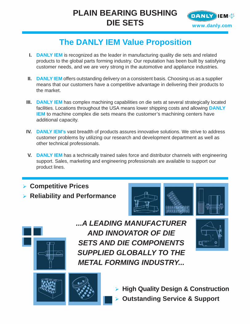
The DANLY IEM Value Proposition I. DANLY IEM is recognized as the leader in manufacturing quality die sets and related products to the global parts forming industry. Our reputation has been built by satisfying customer needs, and we are very strong in the automotive and appliance industries.
II. DANLY IEM offers outstanding delivery on a consistent basis. Choosing us as a supplier means that our customers have a competitive advantage in delivering their products to the market.
III. DANLY IEM has complex machining capabilities on die sets at several strategically located facilities. Locations throughout the USA means lower shipping costs and allowing DANLY IEM to machine complex die sets means the customer’s machining centers have additional capacity.
IV. DANLY IEM’s vast breadth of products assures innovative solutions. We strive to address customer problems by utilizing our research and development department as well as other technical professionals.
V. DANLY IEM has a technically trained sales force and distributor channels with engineering support. Sales, marketing and engineering professionals are available to support our product lines.
...A LEADING MANUFACTURER AND INNOVATOR OF DIE
SETS AND DIE COMPONENTS SUPPLIED GLOBALLY TO THE METAL FORMING INDUSTRY...
Competitive PricesReliability and Performance
High Quality Design & ConstructionOutstanding Service & Support
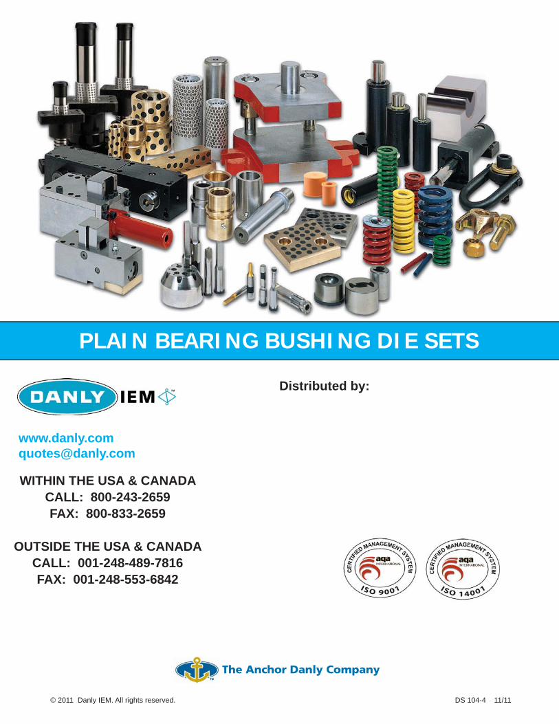
www.danly.com
WITHIN THE USA & CANADA CALL: 800-243-2659FAX: 800-833-2659
OUTSIDE THE USA & CANADA CALL: 001-248-489-7816FAX: 001-248-553-6842
PLAIN BEARING BUSHING DIE SETS
© 2011 Danly IEM. All rights reserved. DS 104-4 11/11
Distributed by:
The Anchor Danly Company