pipeline update 0113 tcm4-538889
TRANSCRIPT
News from DNV to the pipeliNe iNDustry No 01 2013
pipelineupdate
slipipe – New pipeliNe coNcept
pipeliNes iNpolaND
iNterNal corrosioNhealth check
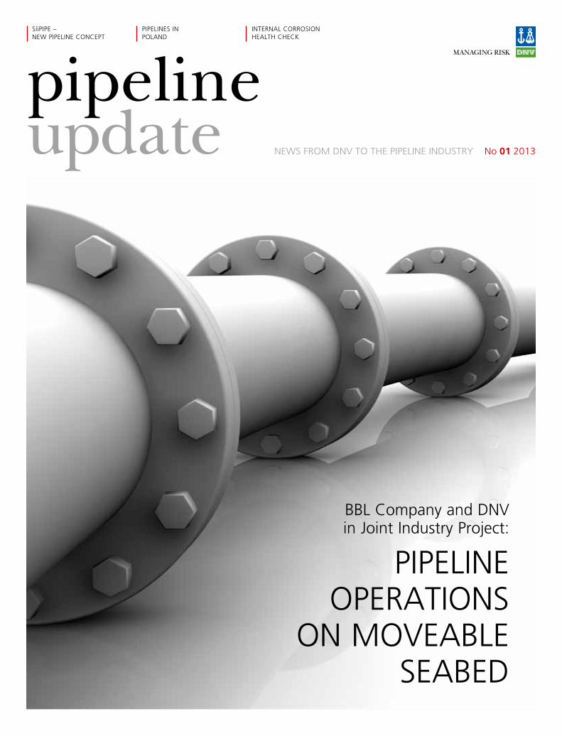
pipeliNe operatioNs
oN moVeable seabeD
bbl company and DNV in Joint industry project:
2 | pipeliNe upDate NO. 1 2013
cONteNts
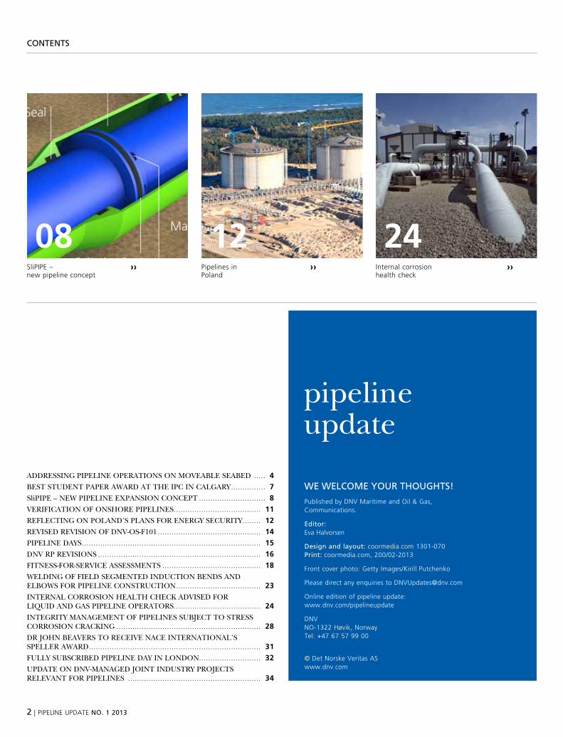
slipipe – new pipeline concept
›› internal corrosionhealth check
››
2408pipelines inpoland
››
12
published by DNV maritime and oil & Gas, communications.
editor: eva halvorsen
Design and layout: coormedia.com 1301-070 Print: coormedia.com, 200/02-2013
front cover photo: Getty images/kirill putchenko
please direct any enquiries to [email protected]
online edition of pipeline update: www.dnv.com/pipelineupdate
DNV No-1322 høvik, Norway tel: +47 67 57 99 00
© Det Norske Veritas as www.dnv.com
We WelcOme yOur thOughts!
pipeline update
Addressing pipeline operAtions on moveAble seAbed ..... 4
best student pAper AwArd At the ipC in CAlgAry ............... 7
slipipe – new pipeline expAnsion ConCept ............................. 8
veriFiCAtion oF onshore pipelines ...................................... 11
reFleCting on polAnd’s plAns For energy seCurity ........ 12
revised revision oF dnv-os-F101 ............................................. 14
pipeline dAys .............................................................................. 15
dnv rp revisions ....................................................................... 16
Fitness-For-serviCe Assessments ........................................... 18
welding oF Field segmented induCtion bends And elbows For pipeline ConstruCtion ..................................... 23
internAl Corrosion heAlth CheCk Advised For liquid And gAs pipeline operAtors ...................................... 24
integrity mAnAgement oF pipelines subjeCt to stress Corrosion CrACking ............................................................... 28
dr john beAvers to reCeive nACe internAtionAl’s speller AwArd ........................................................................... 31
Fully subsCribed pipeline dAy in london........................... 32
updAte on dnv-mAnAged joint industry projeCts relevAnt For pipelines .......................................................... 34
pipeliNe upDate NO. 1 2013 | 3
eDitOrial
Will We sOON kNOW everythiNg We NeeD tO kNOW?
A pipeline is in principle a very simple structure. It is normally made up of a piece of steel with a hole in it. The hole has to be fairly round and the outer diameter has to be bigger than the inner diameter. The question is, how do we make sure this is fulfilled throughout the pipeline’s lifetime?
when i started working with pipelines almost thirty years ago, i was very surprised at how such a simple structure could be so complicated to design, construct and operate.
At that time, dnv did some sporadic r&d work for customers; we assumed that we would soon know everything there was to know about pipe-lines, and therefore wondered what we would do in the future as pipeline engineers.
luckily for the industry, developments have con-tinued. dnv and many other companies have maintained and even increased their r&d activ-ity over the past few years. the more advanced we become and the more we learn, the more we realise how little we know – so the need for r&d is greater than ever!
dnv realises the value of joining forces to reduce the cost of r&d and we therefore pro-mote jips as the main means for r&d. we see an increased interest in our pipeline jips and are therefore going to publish a regular column about our ongoing and planned jips in the dnv pipeline update.
asle venåsGlobal pipeline Director asle.venå[email protected]
to view this update in pdF format on your tablet, scan the qr code or go to www.dnv.com and download the pdF manually.
www.dnv.com
read pipeline update on your tablet!
4 | pipeliNe upDate NO. 1 2013
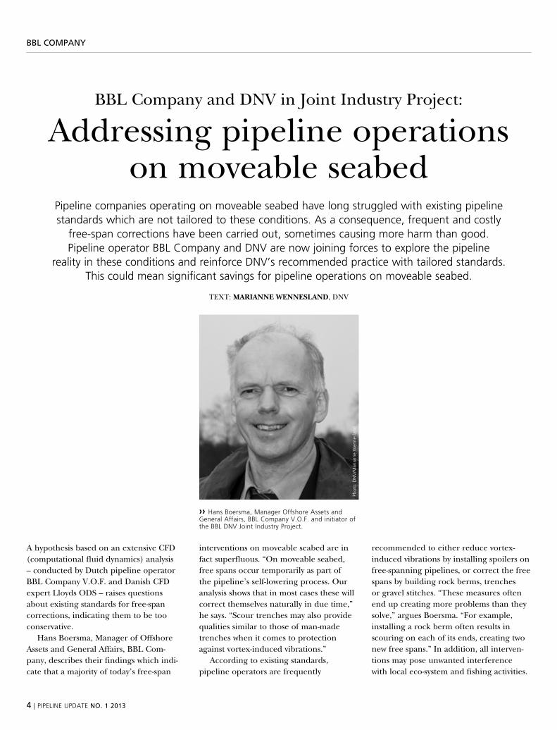
›› hans boersma, manager offshore assets and General affairs, bbl company V.o.f. and initiator of the bbl DNV Joint industry project.
BBl cOmPaNy
bbl Company and dnv in joint industry project:
Addressing pipeline operations on moveable seabed
pipeline companies operating on moveable seabed have long struggled with existing pipeline standards which are not tailored to these conditions. as a consequence, frequent and costly
free-span corrections have been carried out, sometimes causing more harm than good. pipeline operator bbl company and DNV are now joining forces to explore the pipeline
reality in these conditions and reinforce DNV’s recommended practice with tailored standards. this could mean significant savings for pipeline operations on moveable seabed.
text: MArIAnne WenneslAnd, dnv
A hypothesis based on an extensive CFd (computational fluid dynamics) analysis – conducted by dutch pipeline operator bbl Company v.o.F. and danish CFd expert lloyds ods – raises questions about existing standards for free-span corrections, indicating them to be too conservative.
hans boersma, manager of offshore Assets and general Affairs, bbl Com-pany, describes their findings which indi-cate that a majority of today’s free-span
interventions on moveable seabed are in fact superfluous. “on moveable seabed, free spans occur temporarily as part of the pipeline’s self-lowering process. our analysis shows that in most cases these will correct themselves naturally in due time,” he says. “scour trenches may also provide qualities similar to those of man-made trenches when it comes to protection against vortex-induced vibrations.”
According to existing standards, pipeline operators are frequently
recommended to either reduce vortex-induced vibrations by installing spoilers on free-spanning pipelines, or correct the free spans by building rock berms, trenches or gravel stitches. “these measures often end up creating more problems than they solve,” argues boersma. “For example, installing a rock berm often results in scouring on each of its ends, creating two new free spans.” in addition, all interven-tions may pose unwanted interference with local eco-system and fishing activities.
phot
o: D
NV
/mar
iann
e w
enne
slan
d

pipeliNe upDate NO. 1 2013 | 5
BBl cOmPaNy
›› bbl company is located in the Gasunie building (Groningen), considered to be one of the most beautiful office buildings in the Netherlands.
phot
o: D
NV
/mar
iann
e w
enne
slan
d
6 | pipeliNe upDate NO. 1 2013
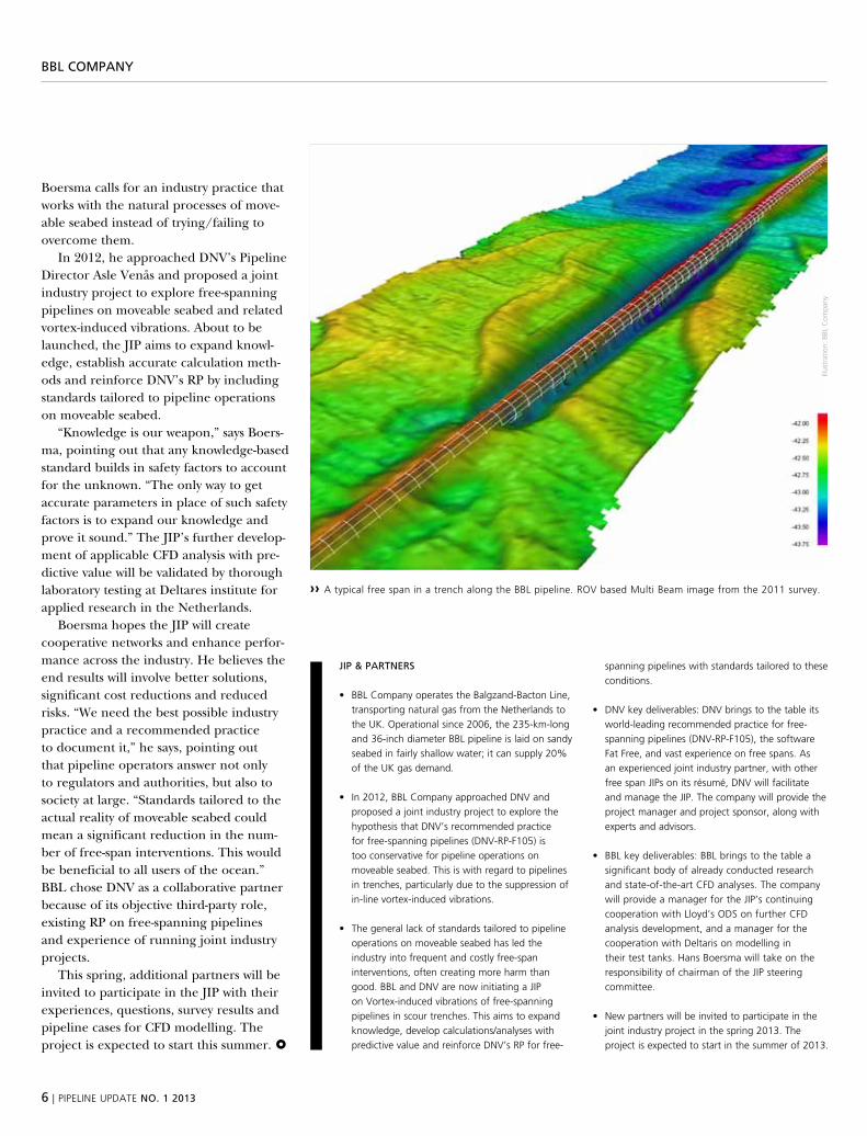
›› a typical free span in a trench along the bbl pipeline. roV based multi beam image from the 2011 survey.
JiP & PartNers
• BBLCompanyoperatestheBalgzand-BactonLine,transporting natural gas from the Netherlands to the uk. operational since 2006, the 235-km-long and 36-inch diameter bbl pipeline is laid on sandy seabed in fairly shallow water; it can supply 20% of the uk gas demand.
• In2012,BBLCompanyapproachedDNVandproposed a joint industry project to explore the hypothesis that DNV’s recommended practice for free-spanning pipelines (DNV-rp-f105) is too conservative for pipeline operations on moveable seabed. this is with regard to pipelines in trenches, particularly due to the suppression of in-line vortex-induced vibrations.
• Thegenerallackofstandardstailoredtopipelineoperations on moveable seabed has led the industry into frequent and costly free-span interventions, often creating more harm than good. bbl and DNV are now initiating a Jip on Vortex-induced vibrations of free-spanning pipelines in scour trenches. this aims to expand knowledge, develop calculations/analyses with predictive value and reinforce DNV’s rp for free-
spanning pipelines with standards tailored to these conditions.
• DNVkeydeliverables:DNVbringstothetableitsworld-leading recommended practice for free-spanning pipelines (DNV-rp-f105), the software fat free, and vast experience on free spans. as an experienced joint industry partner, with other free span Jips on its résumé, DNV will facilitate and manage the Jip. the company will provide the project manager and project sponsor, along with experts and advisors.
• BBLkeydeliverables:BBLbringstothetableasignificant body of already conducted research and state-of-the-art cfD analyses. the company will provide a manager for the Jip’s continuing cooperation with lloyd’s oDs on further cfD analysis development, and a manager for the cooperation with Deltaris on modelling in their test tanks. hans boersma will take on the responsibility of chairman of the Jip steering committee.
• Newpartnerswillbeinvitedtoparticipateinthejoint industry project in the spring 2013. the project is expected to start in the summer of 2013.
BBl cOmPaNy
boersma calls for an industry practice that works with the natural processes of move-able seabed instead of trying/failing to overcome them.
in 2012, he approached dnv’s pipeline director Asle venås and proposed a joint industry project to explore free-spanning pipelines on moveable seabed and related vortex-induced vibrations. About to be launched, the jip aims to expand knowl-edge, establish accurate calculation meth-ods and reinforce dnv’s rp by including standards tailored to pipeline operations on moveable seabed.
“knowledge is our weapon,” says boers-ma, pointing out that any knowledge-based standard builds in safety factors to account for the unknown. “the only way to get accurate parameters in place of such safety factors is to expand our knowledge and prove it sound.” the jip’s further develop-ment of applicable CFd analysis with pre-dictive value will be validated by thorough laboratory testing at deltares institute for applied research in the netherlands.
boersma hopes the jip will create cooperative networks and enhance perfor-mance across the industry. he believes the end results will involve better solutions, significant cost reductions and reduced risks. “we need the best possible industry practice and a recommended practice to document it,” he says, pointing out that pipeline operators answer not only to regulators and authorities, but also to society at large. “standards tailored to the actual reality of moveable seabed could mean a significant reduction in the num-ber of free-span interventions. this would be beneficial to all users of the ocean.” bbl chose dnv as a collaborative partner because of its objective third-party role, existing rp on free-spanning pipelines and experience of running joint industry projects.
this spring, additional partners will be invited to participate in the jip with their experiences, questions, survey results and pipeline cases for CFd modelling. the project is expected to start this summer.
illus
trat
ion:
bbl
com
pany

pipeliNe upDate NO. 1 2013 | 7
iPc aWarD
›› erica marley, engineer, pipeline technology, DNV, whose paper on “assessment of recent experimental Data on collapse capacity of uoe pipelines” won the award for best student paper at the international pipeline conference (ipc).
›› Jake abes is president of DNV canada and is one of the key people in the ipc, and responsible for DNV’s participation in the conference: “DNV has been a strong supporter of the ipc since its inception in 1996, and we actively participate at all levels of the ipc organisation.”
aBOut the iPc
the international pipeline conference (ipc) is organised by volunteers representing international energy corporations, energy and pipeline associa-tions and regulatory agencies. this is a non-profit conference; its proceeds support educational initiatives and research in the pipeline industry.
best student paper award at the ipC in Calgary
erica marley is a second-generation DNV employee, and her paper at the international pipeline conference (ipc) won the award for best student paper. this is the world’s
premier pipeline conference, attended by 1,465 delegates from 45 countries.
text: KrIsTIAn lIndøe, dnv
there were eight finalists presenting for a panel of judges at the conference. erica marley’s paper, “Assessment of recent experimental data on Collapse Capacity of uoe pipelines,” is based on her master thesis at the norwegian university of sci-ence and technology.
erica marley has worked as engineer in the høvik-based unit pipeline technol-ogy since fall of 2011. she has written her project- and master’s thesis in cooperation with the same unit.
her experience includes:
■■ research on pipeline failure modes ■■ Finite element Analysis ■■ structural analysis ■■ probabilistic calibration of design crite-ria for deepwater pipelines
erica marley has also been involved with general pipeline issues such as local buck-ling, trawl interference, pipeline protec-tion, global buckling, wall thickness sizing, on-bottom roughness, on-bottom stability, installation requirements and free-span analyses.
phot
o: D
NV
phot
o: D
NV
8 | pipeliNe upDate NO. 1 2013
sliPiPe
slipipe – new pipeline expansion concept
transporting oil and gas from high-pressure and high-temperature reservoirs through pipelines is a major challenge. slipipe is a new concept developed to deal with pipeline expansion
text: CHIA CHOr YeW, dnv
Finding easy and conventional sources of hydrocarbons has become harder, while global demand for hydrocarbon products continues to grow. oil and gas operators have turned to new geographical areas to tap new resources. these areas are challenging and can be remote, in harsh environments or in deep water, where high-pressure and/or high-temperature (hpht) reservoirs are often found. trans-porting the oil and gas by flowlines and pipelines from these hpht reservoirs is a major challenge. slipipe is a new concept developed to deal with the end expansion of a rigid pipeline subject to hpht.
A pipeline laid on or buried in the sea-bed responds to high pressure and high temperature by expanding against the frictional resistance from the soil, result-ing in axial displacement (also known as end expansion), lateral buckling, upheaval buckling, or a combination of these, depending on whether the pipeline is fully restrained or unrestrained.
in some cases, pipeline walking may occur after the pipeline in operation is cooled down, for example in a shutdown, and heated up for operation and then the thermal cycles are repeated.
these pipeline movements can cause failures in the midline or at the tie-ins connected to the pipeline end and are
critical to the integrity of a pipeline. when a pipeline is subject to high pressure and high temperature, its ends expand lon-gitudinally and exert forces and bending moments onto adjacent tied-in structures connected to it. the tied-in structures must be designed to withstand these expansions and loads. dumping rocks along the pipeline has conventionally been adopted to reduce end expansion. A giant spool installed at the pipeline end is another alternative. they are often used in combination to eliminate end expan-sion when it is very large. however, such
post-lay intervention work is costly and requires a long offshore time.
thus, a major challenge is to improve on the ways the pipeline end movements can be controlled – improvements which are simple, safe and cost effective. slipipe offers a new possibility.
COnCePT slipipe works to reduce the wall force exerted at the tie-in by absorb-ing the end expansion through sliding within itself and simultaneously reducing or eliminating the effective axial compres-sive force in the pipeline.
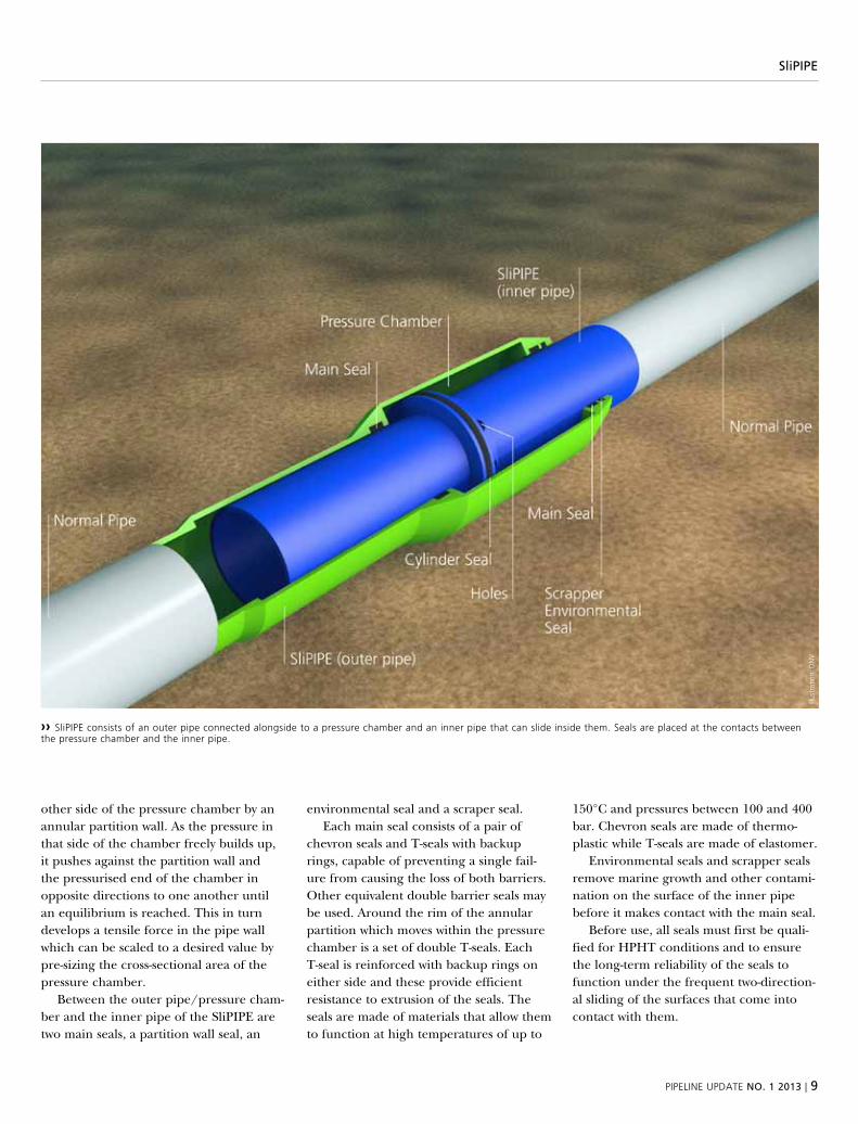
slipipe consists of an outer pipe con-nected alongside to a pressure chamber and an inner pipe that can slide inside them. seals are placed at the contacts between the pressure chamber and the inner pipe. the inner pipe slides in or out of the outer pipes in response to an axial stress that can either be more or less than a certain value. this value is pre-determined in the slipipe design and causes an axial tension in the pipe wall to develop, which opposes the effective axial compressive force component arising from the inner fluid pressure.
the axial tensile pipe wall force is pro-duced by letting fluid pressure in, through holes in the inner pipe, to one side of the pressure chamber, separated from the
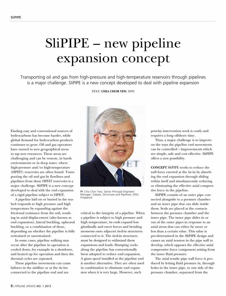
›› chia chor yew, senior principal engineer/manager, subsea, structures and pipelines, DNV,singapore.
phot
o: D
NV
pipeliNe upDate NO. 1 2013 | 9
sliPiPe
other side of the pressure chamber by an annular partition wall. As the pressure in that side of the chamber freely builds up, it pushes against the partition wall and the pressurised end of the chamber in opposite directions to one another until an equilibrium is reached. this in turn develops a tensile force in the pipe wall which can be scaled to a desired value by pre-sizing the cross-sectional area of the pressure chamber.
between the outer pipe/pressure cham-ber and the inner pipe of the slipipe are two main seals, a partition wall seal, an
environmental seal and a scraper seal. each main seal consists of a pair of
chevron seals and t-seals with backup rings, capable of preventing a single fail-ure from causing the loss of both barriers. other equivalent double barrier seals may be used. Around the rim of the annular partition which moves within the pressure chamber is a set of double t-seals. each t-seal is reinforced with backup rings on either side and these provide efficient resistance to extrusion of the seals. the seals are made of materials that allow them to function at high temperatures of up to
150°C and pressures between 100 and 400 bar. Chevron seals are made of thermo-plastic while t-seals are made of elastomer.
environmental seals and scrapper seals remove marine growth and other contami-nation on the surface of the inner pipe before it makes contact with the main seal.
before use, all seals must first be quali-fied for hpht conditions and to ensure the long-term reliability of the seals to function under the frequent two-direction-al sliding of the surfaces that come into contact with them.
›› slipipe consists of an outer pipe connected alongside to a pressure chamber and an inner pipe that can slide inside them. seals are placed at the contacts between the pressure chamber and the inner pipe.
illus
trat
ion:
DN
V
10 | pipeliNe upDate NO. 1 2013
sliPiPe
several practical issues that will influence the operation of the slipipe were stud-ied and feasible ways to overcome them looked into, such as:
■■ the double seals at the annular parti-tion wall are relied upon to keep the differential pressure between the non-pressurised compartment and the pres-sured compartment of the chamber. to safeguard against the pressures on either side of the partition wall equalising over time, a one-way relief valve, suitable for underwater application, can be installed at the far corner of the non-pressurised compartment through which any built-up pressure in the compartment can be vented out into the sea. Alternatively, a small pipe connecting the non-pressur-ised compartment to a faraway existing flare-off facility, if available, will produce the same effect.
■■ Assembling the components and seals together to create the slipipe is fea-sible by casting, forging, welding and assembling the components in a certain production sequence. damage to the seals from the heat generated by welding parts together can be avoided by careful selection of the welding locations.
■■ the seals can be inspected after the final factory-acceptance test by modifying the free end of the pressure chamber to create a pair of flanges with a metal seal between them, one flange connected to the chamber body and the other con-nected to the chamber end. the flanges can be unbolted to disassemble the com-ponents so that the seals can be inspect-ed. the metal seal located between the flanges is then replaced with a new one before the slipipe is reassembled.
■■ in order for the main seal to hold against leaks, it is crucial that the envi-ronmental and scraper seal can be relied
upon to clean the surface of the inner pipe that comes into contact with the main seal. this can be improved by extending the free end of the pressure chamber using external tubular hous-ing that has a tight-fit end and is long enough to shield the contactable inner-pipe surface from fouling.
InsTAllATIOn A slipipe used for absorbing end expansion may be pre-installed on a plet which is then trans-ported and installed offshore on the end of the pipeline, lowered onto the seabed and connected to a manifold or riser via a short tie-in spool. A misalignment flange may be included.
Alternatively, a direct tie-in (without a plet and short tie-in spool) is also feasi-ble with the use of a suitable installation guide currently available on the market, e.g. subsea installation guide (sig). the sig is placed on the subsea structure close to the connection point and guides the pipeline end towards the hub on the sub-sea structures until they are separated by a small gap. the slipipe is then allowed to slide until the small gap is completely closed and the connectors clamped together. no post-installation metrology, fabrication of the short spool, additional spool installation or subsea tie-in need be performed. in the direct tie-in method, slipipes have to be locked to restrict any uncontrolled movement and the lock released before tie-in.
A slipipe must be designed to have at least the same capacity as the adjacent linepipe, which has already been designed to resist the maximum tensile forces and bending moments.
APPlICATIOn slipipe is a concept well-suited for installing tie-ins between a sub-merged rigid pipeline and a subsea well, subsea structure or riser, typically from 10.75 to 24 inches (273 to 610 mm) in diameter, with operating temperatures up
to 150°C and a pressure range from 100 to 400 bar.
Compared to a giant tie-in spool, sli-pipe is a relatively simple yet effective alternative means to eliminate the effects of end expansion on tie-in structures.
key advantages: ■■ slipipe avoids the fabrication and com-plicated installation associated with giant spools.
■■ slipipe minimises costly post-installation subsea intervention work.
■■ slipipe is space-efficient and ideal in areas congested with many subsea facilities, as are often encountered in brownfield modification work, where safeguarding the facilities’ integrity dur-ing intervention work can be a formida-ble task.
dnv has been instrumental in develop-ing and upgrading the safety and integrity regime and standards for offshore pipe-lines over the past few decades. today, more than 65% of the world’s offshore pipelines are designed and installed to dnv’s offshore pipeline standard, includ-ing several recent ones laid in deep waters.
slipipe is conceptual and will require refinement and engineering through basic and detailed design before it can be real-ised in an actual project. A global team of experienced engineers from singapore, oslo, perth and groningen, combining youth and experience and headed by dnv in singapore, has developed the concept. the team has also taken into account com-ments received from the offshore pipeline industry. besides a university professor, the personnel consulted are from two major installation contractors and a seal company.
pipeliNe upDate NO. 1 2013 | 11
veriFicatiON OF ONshOre PiPeliNes
verification of onshore pipelinesDNV has launched a new service specification for
the verification of onshore pipeline systems.
text: AlI sIsAn, dnv
historically, onshore pipeline systems have not usually been subject to independent verification. however, with changing regu-latory environments and industry norms requiring greater scrutiny of hazardous installations in public areas, pipeline oper-ators increasingly need to involve an inde-pendent verifier to provide the required level of confidence that their facilities comply with regulatory requirements, rec-ognised codes and standards and project specifications.
dnv’s new service specification, dnv-dss-316, outlines dnv recommendations for the scope and depth of involvement by a verification body in onshore pipeline systems. the standard provides criteria for, and guidance on, the verification of com-plete onshore pipeline systems and the integrity of parts or phases of a pipeline system.
rIsK-bAsed verIfICATIOn similar to other dnv service specifications, dnv-dss-316 follows a risk-based approach. the level of verification activity is differentiated according to the risk. if the risk associated with the pipeline system is higher, the level of verification involvement is higher. Con-versely, if the risk associated with the pipe-line is lower, the level of verification activi-ties can be reduced without any reduction in their effectiveness.
benefIT third-party verification of onshore pipelines has the benefit of giving the stakeholders confidence that:
■■ the onshore pipeline system has suf-ficient integrity to fulfil its specified requirements
■■ risks to personnel and the environment associated with the onshore pipeline sys-tem are as low as reasonably practicable
Additionally, it is good business practice to subject critical work to a third-party check as this minimises the possibility of errors remaining undetected. third-party verifi-cation will ensure that the verifier has an independent view and perspective when performing this activity.
verification can also be used as a part of the project risk management when the failure of pipeline systems may expose the interested parties to various risks: safety, environmental, economic, regulatory, political and reputational.
servICe OvervIeW dnv-dss-316 out-lines different levels of verification involve-ment to be selected by the customer, thus ensuring that the verification body’s scope is well defined. Further, by stating this level on the final verification statement, the recipients of the statement will also be informed of the scope.
the standard describes dnv’s verifica-tion services for onshore pipeline systems and provides guidance for customers and other parties on the selection of the level of involvement of those carrying out the verification activities. moreover, it provides a common communication platform for describing the extent of the verification activities.
A verification process may relate to the following project phases:■■ Conceptual design■■ Front end engineering design (Feed)■■ detail design■■ Construction
A statement of Compliance can be issued by dnv on completion of each particular project phase, and will be based on a dedi-cated verification report.
this service specification has been long awaited by the industry; it complements the series of offshore pipeline guidance, recommended practices and specification documents in use by many operators and pipeline supporting companies worldwide. like other dnv rules and recommended practices, dnv-dss-316 may be down-loaded free of charge from www.dnv.com as from 1 April 2013.
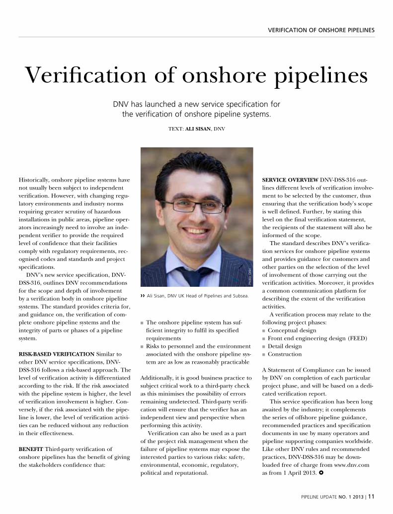
›› ali sisan, DNV uk head of pipelines and subsea.
phot
o: D
NV
12 | pipeliNe upDate NO. 1 2013
eNergy security
reflecting on poland’s plans for energy security
there are a number of measures being taken in poland to ensure security of energy supply, not least the construction of a new terminal and investment in shale gas potential. where does DNV fit?
text: JAn TAlAsKA, dnv
due to its insufficient natural deposits of oil and gas, poland is developing pipe-line construction and operation projects intended to ensure energy security, which will contribute to sustainable development in all regions in the country.
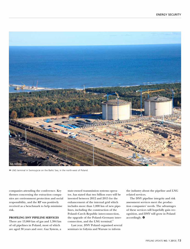
one of the measures being taken is to diversify the natural gas supply and create an alternative to supply from russia. in order to make that happen there is to be a lng terminal built in swinoujscie, which is a city and seaport on the baltic sea, located in the north-west of poland. it is to be the largest terminal in the baltic sea with a capacity of five billion cubic metres (bcm) per annum, with a possibility to increase the dispatch capacity to 7.5 bcm per annum.
the terminal, which is designed to off take and re-gasify liquefied gas has an investment of more than one billion euro. A key stakeholder, polskie lng, a subsidi-ary company of one of the largest polish oil and gas companies with a sales revenue of 5,300 meur, has chosen saipem (eni group) as an engineering, procurement, Construction (epC) company to build the terminal.
on 28 september 2011, dnv signed an agreement with polskie lng for complex verification of the terminal. the scope of work included verification of management system status, people and competence, terminal equipment readiness, commis-sioning & start-up plan & methods, readi-ness to operate & maintain, shipping & jetty operations, and emergency response capability.
dnv uk is involved and supporting dnv poland in the project. polskie lng is to adopt a management system based on the 8th edition for the isrs™ (inter-national safety rating system) and use dnv as its verifier. moreover, dnv is to evaluate the capability of competencies of the personnel.
THe develOPMenT Of sHAle gAs the polish geological institute has esti-mated poland’s recoverable shale gas reserves at 346–768 billion m3 and the cal-culation is widely perceived to be conserva-tive. this is 2.5–5.5 times more than the resources of the documented conventional deposits (145 billion m3). together, both sources would meet poland’s demand for gas over 35–65 years.
exploration and recovery of shale gas is not only being pioneered by the largest polish noCs, but also by the world’s shale gas industry leaders, mainly from the usA and Canada. Companies such as bnk, Chevron, marathon oil, total, nexen, and Conocophillips are vying for the lucrative shale plays in poland.
dnv poland is focusing on developing a team to provide verification services, in order to support the growing need for ser-vices to support the shale gas revolution.
At a warsaw shale gas conference in november 2012, dnv launched its new recommended practice dnv-rp-u301 – risk management of shale gas devel-opments and operations. the standard attracted much interest from the many
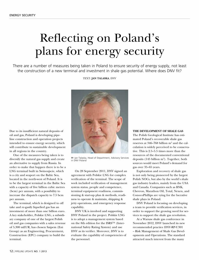
›› Jan talaska, head of Department, advisory services in DNV poland
phot
o: D
NV
pipeliNe upDate NO. 1 2013 | 13
eNergy security
›› lNG terminal in swinoujscie on the baltic sea, in the north-west of poland.
phot
o: G
aZ
syss
tem
companies attending the conference. key themes concerning the extraction compa-nies are environment protection and social responsibility, and the rp was positively received as a benchmark to help minimise risk.
PrOfIlIng dnv PIPelIne servICes there are 13,860 km of gas and 1,384 km of oil pipelines in poland, most of which are aged 30 years and over. gaz system, a
state-owned transmission systems opera-tor, has stated that two billion euro will be invested between 2012 and 2015 for the enhancement of the internal grid which includes more than 1,000 km of new pipe-lines, including the construction of the poland–Czech republic interconnection, the upgrade of the poland–germany inter-connection, and the lng terminal.”
last year, dnv poland organised several seminars in gdynia and warsaw to inform
the industry about the pipeline and lng related services.
the dnv pipeline integrity and risk assessment services meet the produc-tion companies’ needs. the advantages of these services will hopefully gain rec-ognition, and dnv will grow in poland accordingly.
14 | pipeliNe upDate NO. 1 2013
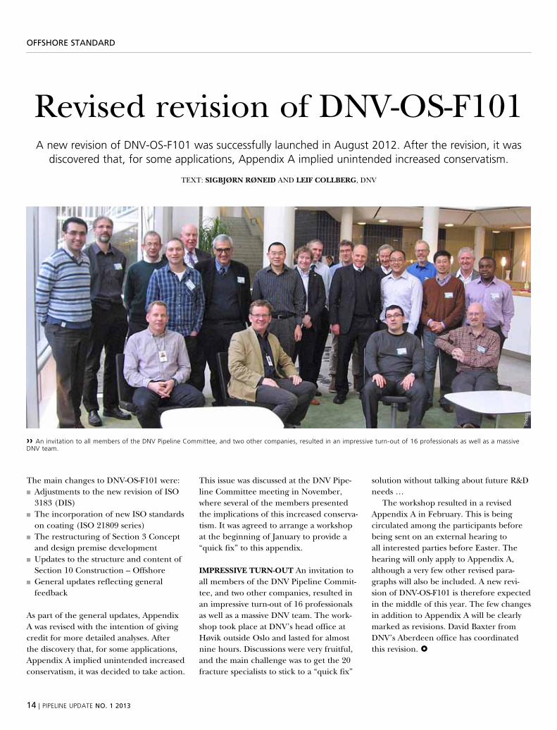
›› an invitation to all members of the DNV pipeline committee, and two other companies, resulted in an impressive turn-out of 16 professionals as well as a massive DNV team.
OFFshOre staNDarD
revised revision of dnv-os-F101a new revision of DNV-os-f101 was successfully launched in august 2012. after the revision, it was
discovered that, for some applications, appendix a implied unintended increased conservatism.
text: sIgbJørn røneId And leIf COllberg, dnv
the main changes to dnv-os-F101 were:■■ Adjustments to the new revision of iso 3183 (dis)
■■ the incorporation of new iso standards on coating (iso 21809 series)
■■ the restructuring of section 3 Concept and design premise development
■■ updates to the structure and content of section 10 Construction – offshore
■■ general updates reflecting general feedback
As part of the general updates, Appendix A was revised with the intention of giving credit for more detailed analyses. After the discovery that, for some applications, Appendix A implied unintended increased conservatism, it was decided to take action.
this issue was discussed at the dnv pipe-line Committee meeting in november, where several of the members presented the implications of this increased conserva-tism. it was agreed to arrange a workshop at the beginning of january to provide a “quick fix” to this appendix.
IMPressIve Turn-OuT An invitation to all members of the dnv pipeline Commit-tee, and two other companies, resulted in an impressive turn-out of 16 professionals as well as a massive dnv team. the work-shop took place at dnv’s head office at høvik outside oslo and lasted for almost nine hours. discussions were very fruitful, and the main challenge was to get the 20 fracture specialists to stick to a “quick fix”
solution without talking about future r&d needs …
the workshop resulted in a revised Appendix A in February. this is being circulated among the participants before being sent on an external hearing to all interested parties before easter. the hearing will only apply to Appendix A, although a very few other revised para-graphs will also be included. A new revi-sion of dnv-os-F101 is therefore expected in the middle of this year. the few changes in addition to Appendix A will be clearly marked as revisions. david baxter from dnv’s Aberdeen office has coordinated this revision.
phot
o: D
NV
pipeliNe upDate NO. 1 2013 | 15
PiPeliNe eveNts
pipeline events
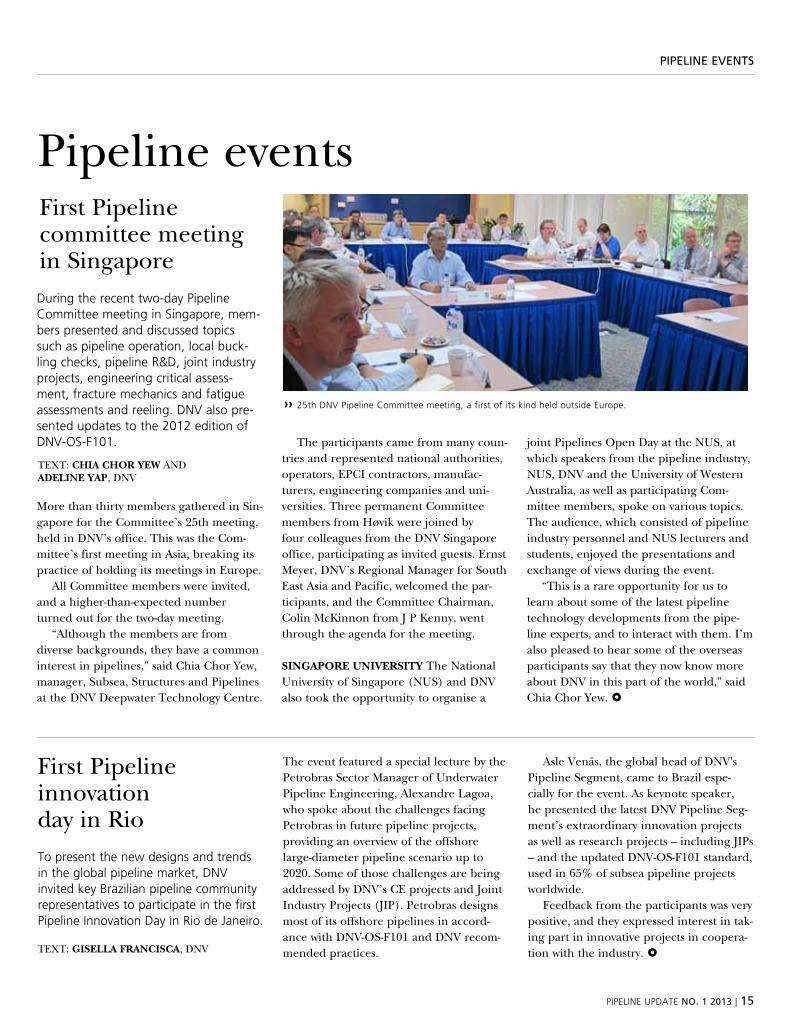
During the recent two-day pipeline committee meeting in singapore, mem-bers presented and discussed topics such as pipeline operation, local buck-ling checks, pipeline r&D, joint industry projects, engineering critical assess-ment, fracture mechanics and fatigue assessments and reeling. DNV also pre-sented updates to the 2012 edition of DNV-os-f101.
more than thirty members gathered in sin-gapore for the Committee’s 25th meeting, held in dnv’s office. this was the Com-mittee’s first meeting in Asia, breaking its practice of holding its meetings in europe.
All Committee members were invited, and a higher-than-expected number turned out for the two-day meeting.
“Although the members are from diverse backgrounds, they have a common interest in pipelines,” said Chia Chor yew, manager, subsea, structures and pipelines at the dnv deepwater technology Centre.
the participants came from many coun-tries and represented national authorities, operators, epCi contractors, manufac-turers, engineering companies and uni-versities. three permanent Committee members from høvik were joined by four colleagues from the dnv singapore office, participating as invited guests. ernst meyer, dnv’s regional manager for south east Asia and pacific, welcomed the par-ticipants, and the Committee Chairman, Colin mckinnon from j p kenny, went through the agenda for the meeting.
sIngAPOre unIversITY the national university of singapore (nus) and dnv also took the opportunity to organise a
joint pipelines open day at the nus, at which speakers from the pipeline industry, nus, dnv and the university of western Australia, as well as participating Com-mittee members, spoke on various topics. the audience, which consisted of pipeline industry personnel and nus lecturers and students, enjoyed the presentations and exchange of views during the event.
“this is a rare opportunity for us to learn about some of the latest pipeline technology developments from the pipe-line experts, and to interact with them. i’m also pleased to hear some of the overseas participants say that they now know more about dnv in this part of the world,” said Chia Chor yew.
to present the new designs and trends in the global pipeline market, DNV invitedkeyBrazilianpipelinecommunityrepresentatives to participate in the first pipeline innovation Day in rio de Janeiro.
the event featured a special lecture by the petrobras sector manager of underwater pipeline engineering, Alexandre lagoa, who spoke about the challenges facing petrobras in future pipeline projects, providing an overview of the offshore large-diameter pipeline scenario up to 2020. some of those challenges are being addressed by dnv’s Ce projects and joint industry projects (jip). petrobras designs most of its offshore pipelines in accord-ance with dnv-os-F101 and dnv recom-mended practices.
Asle venås, the global head of dnv's pipeline segment, came to brazil espe-cially for the event. As keynote speaker, he presented the latest dnv pipeline seg-ment’s extraordinary innovation projects as well as research projects – including jips – and the updated dnv-os-F101 standard, used in 65% of subsea pipeline projects worldwide.
Feedback from the participants was very positive, and they expressed interest in tak-ing part in innovative projects in coopera-tion with the industry.
›› 25th DNV pipeline committee meeting, a first of its kind held outside europe.
First pipeline committee meeting in singapore
text: CHIA CHOr YeW And AdelIne YAP, dnv
text: gIsellA frAnCIsCA, dnv
First pipeline innovation day in rio
16 | pipeliNe upDate NO. 1 2013
DNv recOmmeNDeD Practices
dnv rp revisionsthe DNV recommended practices DNV-rp-f101 ‘corroded pipelines’ and DNV-rp-f116 ‘integrity management of submarine pipeline systems’ have both been developed in close cooperation with the industry to support decision-making processes related to
maintaining the integrity of pipeline systems. both rps have had Joint industry projects (Jips) ongoing since 2011; based on this work, new revisions will be issued during 2013.
text: felIx sAInT-vICTOr, dnv
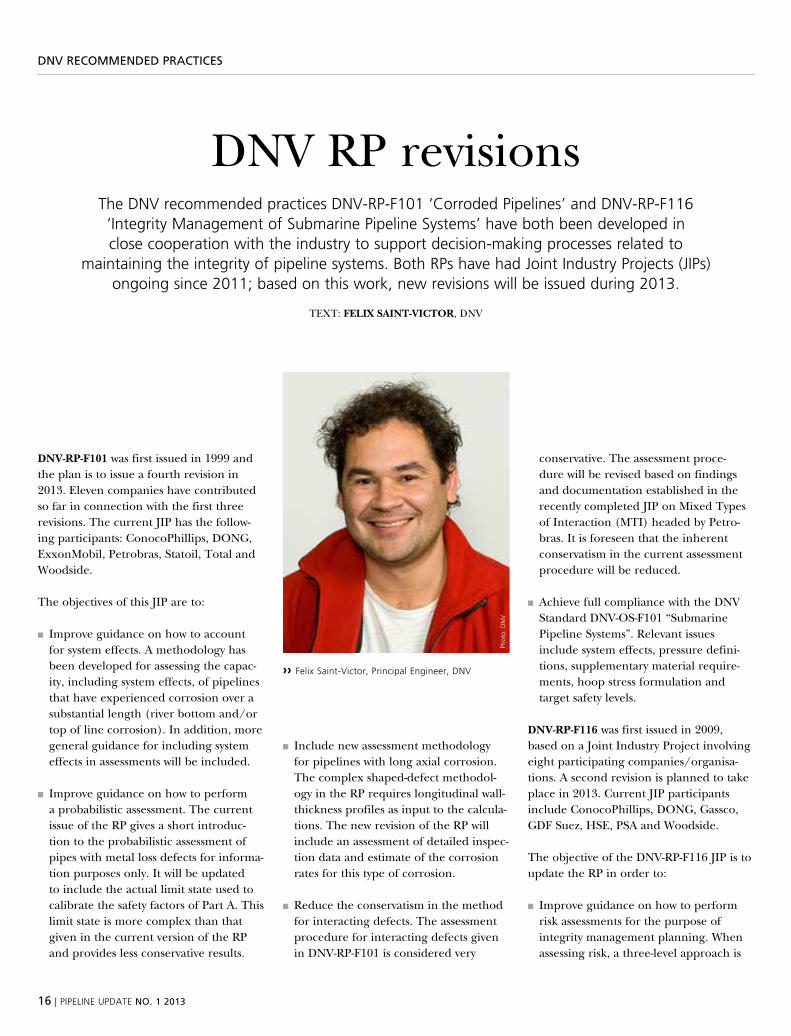
dnv-rP-f101 was first issued in 1999 and the plan is to issue a fourth revision in 2013. eleven companies have contributed so far in connection with the first three revisions. the current jip has the follow-ing participants: Conocophillips, dong, exxonmobil, petrobras, statoil, total and woodside.
the objectives of this jip are to:
■■ improve guidance on how to account for system effects. A methodology has been developed for assessing the capac-ity, including system effects, of pipelines that have experienced corrosion over a substantial length (river bottom and/or top of line corrosion). in addition, more general guidance for including system effects in assessments will be included.
■■ improve guidance on how to perform a probabilistic assessment. the current issue of the rp gives a short introduc-tion to the probabilistic assessment of pipes with metal loss defects for informa-tion purposes only. it will be updated to include the actual limit state used to calibrate the safety factors of part A. this limit state is more complex than that given in the current version of the rp and provides less conservative results.
■■ include new assessment methodology for pipelines with long axial corrosion. the complex shaped-defect methodol-ogy in the rp requires longitudinal wall-thickness profiles as input to the calcula-tions. the new revision of the rp will include an assessment of detailed inspec-tion data and estimate of the corrosion rates for this type of corrosion.
■■ reduce the conservatism in the method for interacting defects. the assessment procedure for interacting defects given in dnv-rp-F101 is considered very
conservative. the assessment proce-dure will be revised based on findings and documentation established in the recently completed jip on mixed types of interaction (mti) headed by petro-bras. it is foreseen that the inherent conservatism in the current assessment procedure will be reduced.
■■ Achieve full compliance with the dnv standard dnv-os-F101 “submarine pipeline systems”. relevant issues include system effects, pressure defini-tions, supplementary material require-ments, hoop stress formulation and target safety levels.
dnv-rP-f116 was first issued in 2009, based on a joint industry project involving eight participating companies/organisa-tions. A second revision is planned to take place in 2013. Current jip participants include Conocophillips, dong, gassco, gdF suez, hse, psA and woodside.
the objective of the dnv-rp-F116 jip is to update the rp in order to:
■■ improve guidance on how to perform risk assessments for the purpose of integrity management planning. when assessing risk, a three-level approach is
›› felix saint-Victor, principal engineer, DNV
phot
o: D
NV
pipeliNe upDate NO. 1 2013 | 17
DNv recOmmeNDeD Practices
recommended by the current issue of dnv-rp-F116: from level 1 (screening level) to level 3 (fully probabilistic). however, detailed guidelines were not presented. the work carried out by the current dnv-rp-F116 jip has provided further guidance on such a levelled approach. For example, flow charts have been developed for the following threats for level 1 assessments: internal and external corrosion, trawl interfer-ence, anchoring, dropped objects, vessel impact, global buckling (exposed pipe-line), global buckling (buried pipeline), on-bottom stability and free spanning. guidelines for levels 2 and 3 have also been developed.
■■ provide guidance on integrity manage-ment review and potential key perfor-mance indicators. A set of review state-ments has been developed to generally evaluate integrity management as a whole based on the existing dnv-rp-F116 with a focus on the core integrity management process. in addition, a set of potential kpis will be presented based on a combined integrity-management and barrier-philosophy mind-set. the presented set of potential kpis can be used as input when choosing indicators to be included in existing or planned company kpi systems for following up actual pipeline systems in more detail.
Addressing the above issues will benefit the oil and gas industry in terms of access to improved guidelines which may allow:■■ extended in-service operation for a cor-roded pipeline
■■ Avoidance of unnecessary costly repairs and replacements
■■ planning of activities with input from risk assessments based on balanced evaluations of both technical and non-technical issues
■■ Continuous improvement of integrity management systems.
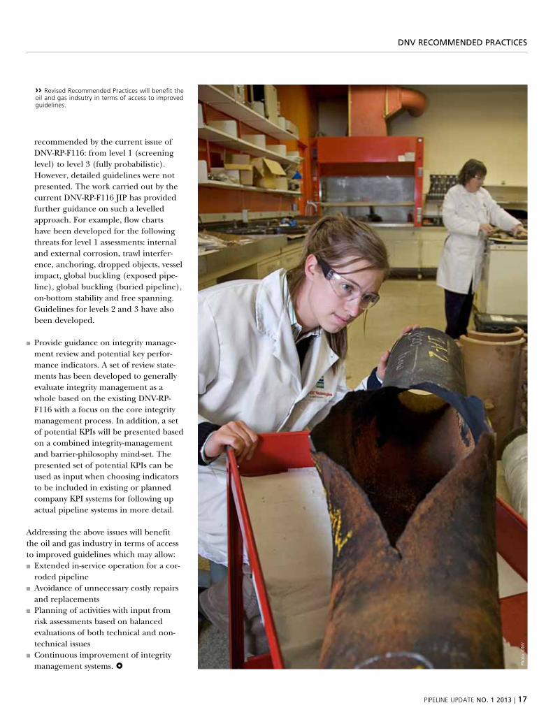
›› revised recommended practices will benefit the oil and gas indsutry in terms of access to improved guidelines.
phot
o: D
NV
18 | pipeliNe upDate NO. 1 2013
FitNess-FOr-service assessmeNts
Fitness-for-service assessmentsidentify integrity concerns and help operators
restore normal operations
aged pipelines that contain corrosion, cracking, and deformation anomalies are occasionally subject to pressure reductions to ensure safe operation. sometimes these reductions
are voluntary, but they are often imposed by a regulatory agency following a release or other incident. pressure reductions imposed by a regulatory agency can typically be lifted
once the pipeline operator completes corrective actions outlined by the agency.
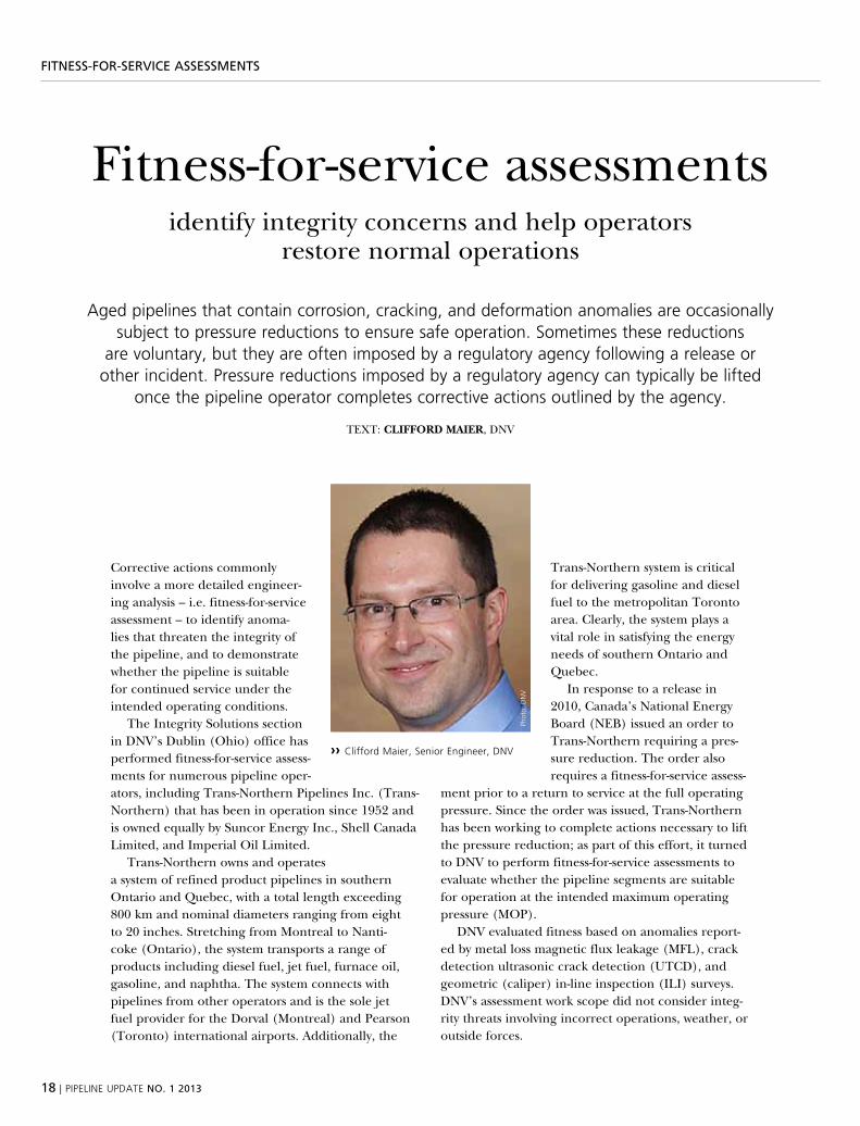
text: ClIffOrd MAIer, dnv
Corrective actions commonly involve a more detailed engineer-ing analysis – i.e. fitness-for-service assessment – to identify anoma-lies that threaten the integrity of the pipeline, and to demonstrate whether the pipeline is suitable for continued service under the intended operating conditions.
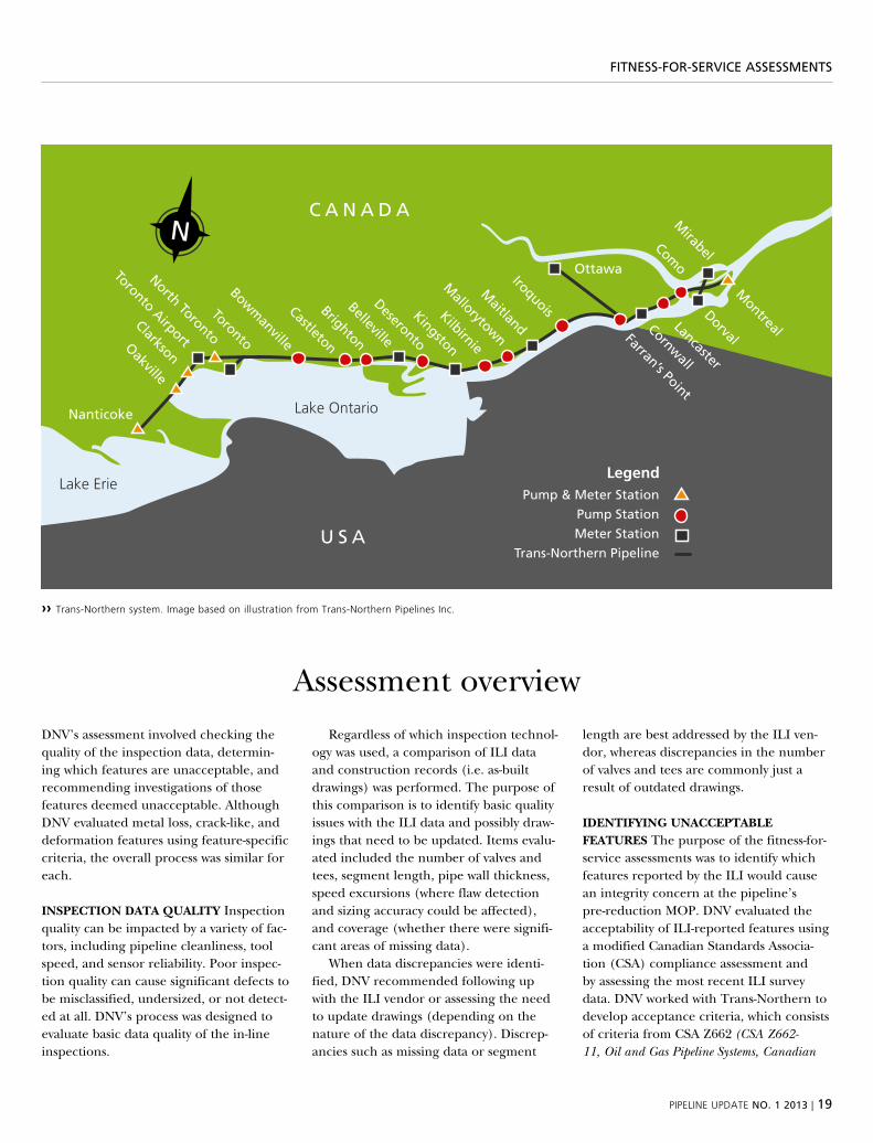
the integrity solutions section in dnv’s dublin (ohio) office has performed fitness-for-service assess-ments for numerous pipeline oper-ators, including trans-northern pipelines inc. (trans-northern) that has been in operation since 1952 and is owned equally by suncor energy inc., shell Canada limited, and imperial oil limited.
trans-northern owns and operates a system of refined product pipelines in southern ontario and quebec, with a total length exceeding 800 km and nominal diameters ranging from eight to 20 inches. stretching from montreal to nanti-coke (ontario), the system transports a range of products including diesel fuel, jet fuel, furnace oil, gasoline, and naphtha. the system connects with pipelines from other operators and is the sole jet fuel provider for the dorval (montreal) and pearson (toronto) international airports. Additionally, the
trans-northern system is critical for delivering gasoline and diesel fuel to the metropolitan toronto area. Clearly, the system plays a vital role in satisfying the energy needs of southern ontario and quebec.
in response to a release in 2010, Canada’s national energy board (neb) issued an order to trans-northern requiring a pres-sure reduction. the order also requires a fitness-for-service assess-
ment prior to a return to service at the full operating pressure. since the order was issued, trans-northern has been working to complete actions necessary to lift the pressure reduction; as part of this effort, it turned to dnv to perform fitness-for-service assessments to evaluate whether the pipeline segments are suitable for operation at the intended maximum operating pressure (mop).
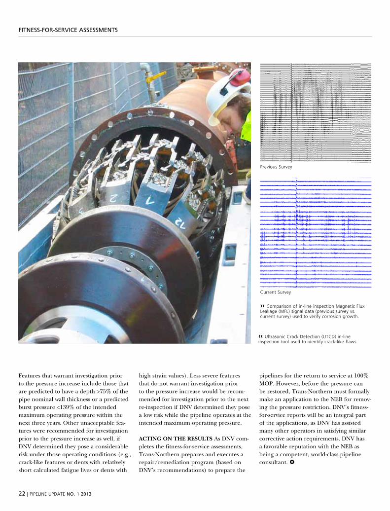
dnv evaluated fitness based on anomalies report-ed by metal loss magnetic flux leakage (mFl), crack detection ultrasonic crack detection (utCd), and geometric (caliper) in-line inspection (ili) surveys. dnv’s assessment work scope did not consider integ-rity threats involving incorrect operations, weather, or outside forces.
›› clifford maier, senior engineer, DNV
phot
o: D
NV
pipeliNe upDate NO. 1 2013 | 19
FitNess-FOr-service assessmeNts
Assessment overview
dnv’s assessment involved checking the quality of the inspection data, determin-ing which features are unacceptable, and recommending investigations of those features deemed unacceptable. Although dnv evaluated metal loss, crack-like, and deformation features using feature-specific criteria, the overall process was similar for each.
InsPeCTIOn dATA QuAlITY inspection quality can be impacted by a variety of fac-tors, including pipeline cleanliness, tool speed, and sensor reliability. poor inspec-tion quality can cause significant defects to be misclassified, undersized, or not detect-ed at all. dnv’s process was designed to evaluate basic data quality of the in-line inspections.
regardless of which inspection technol-ogy was used, a comparison of ili data and construction records (i.e. as-built drawings) was performed. the purpose of this comparison is to identify basic quality issues with the ili data and possibly draw-ings that need to be updated. items evalu-ated included the number of valves and tees, segment length, pipe wall thickness, speed excursions (where flaw detection and sizing accuracy could be affected), and coverage (whether there were signifi-cant areas of missing data).
when data discrepancies were identi-fied, dnv recommended following up with the ili vendor or assessing the need to update drawings (depending on the nature of the data discrepancy). discrep-ancies such as missing data or segment
length are best addressed by the ili ven-dor, whereas discrepancies in the number of valves and tees are commonly just a result of outdated drawings.
IdenTIfYIng unACCePTAble feATures the purpose of the fitness-for-service assessments was to identify which features reported by the ili would cause an integrity concern at the pipeline’s pre-reduction mop. dnv evaluated the acceptability of ili-reported features using a modified Canadian standards Associa-tion (CsA) compliance assessment and by assessing the most recent ili survey data. dnv worked with trans-northern to develop acceptance criteria, which consists of criteria from CsA Z662 (CSA Z662-11, Oil and Gas Pipeline Systems, Canadian
Lake Ontario
Lake Erie
C A N A D A
U S A
Nanticoke
Oakville
Clarkson
Toronto Airport
North Toronto
Toronto
Castleton
Bowmanville
Brighton
Belleville
Kingston
Deseronto
Kilbirnie
Mallorytown
Ottawa
Maitland
Iroquois
Farran’s Point
Cornwall
Lancaster
Como
Dorval
Montreal
Mirabel
LegendPump & Meter Station
Pump StationMeter Station
Trans-Northern Pipeline
N
›› trans-Northern system. image based on illustration from trans-Northern pipelines inc.
20 | pipeliNe upDate NO. 1 2013
FitNess-FOr-service assessmeNts
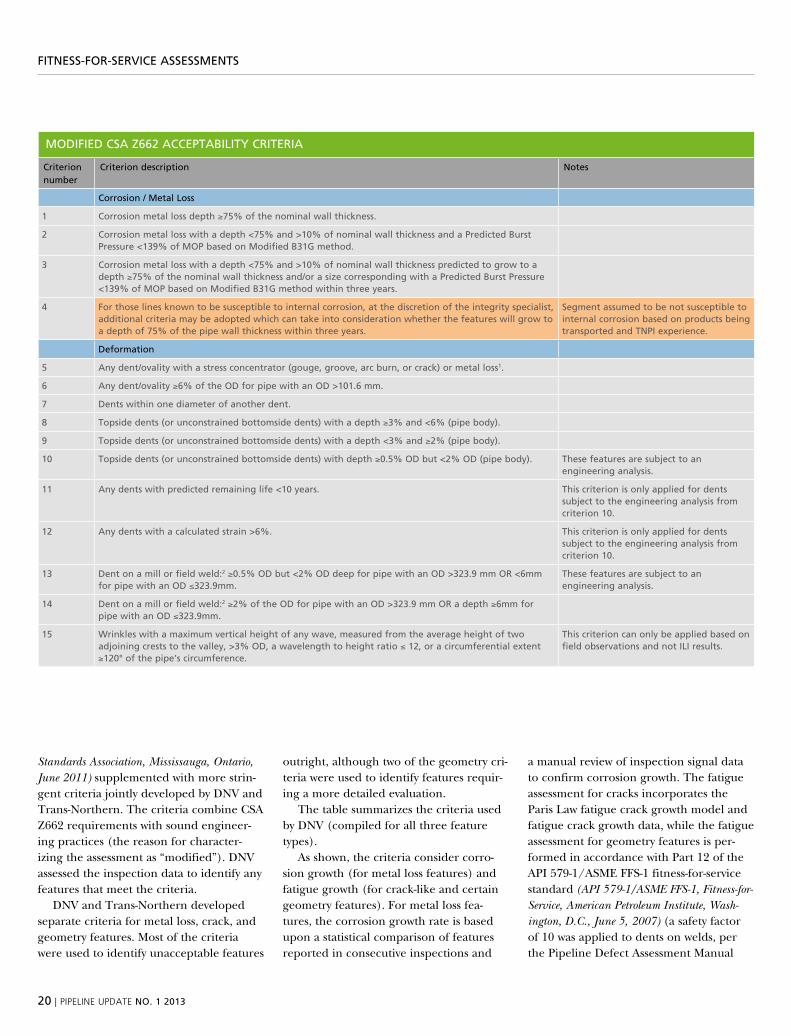
Standards Association, Mississauga, Ontario, June 2011) supplemented with more strin-gent criteria jointly developed by dnv and trans-northern. the criteria combine CsA Z662 requirements with sound engineer-ing practices (the reason for character-izing the assessment as “modified”). dnv assessed the inspection data to identify any features that meet the criteria.
dnv and trans-northern developed separate criteria for metal loss, crack, and geometry features. most of the criteria were used to identify unacceptable features
outright, although two of the geometry cri-teria were used to identify features requir-ing a more detailed evaluation.
the table summarizes the criteria used by dnv (compiled for all three feature types).
As shown, the criteria consider corro-sion growth (for metal loss features) and fatigue growth (for crack-like and certain geometry features). For metal loss fea-tures, the corrosion growth rate is based upon a statistical comparison of features reported in consecutive inspections and
a manual review of inspection signal data to confirm corrosion growth. the fatigue assessment for cracks incorporates the paris law fatigue crack growth model and fatigue crack growth data, while the fatigue assessment for geometry features is per-formed in accordance with part 12 of the Api 579-1/Asme FFs-1 fitness-for-service standard (API 579-1/ASME FFS-1, Fitness-for-Service, American Petroleum Institute, Wash-ington, D.C., June 5, 2007) (a safety factor of 10 was applied to dents on welds, per the pipeline defect Assessment manual
mODiFieD csa Z662 accePtaBility criteria
criterion number
criterion description Notes
corrosion / metal loss
1 corrosion metal loss depth ≥75% of the nominal wall thickness.
2 corrosion metal loss with a depth <75% and >10% of nominal wall thickness and a Predicted Burst Pressure <139% of mOP based on modified B31g method.
3 corrosion metal loss with a depth <75% and >10% of nominal wall thickness predicted to grow to a depth ≥75% of the nominal wall thickness and/or a size corresponding with a Predicted Burst Pressure <139% of mOP based on modified B31g method within three years.
4 For those lines known to be susceptible to internal corrosion, at the discretion of the integrity specialist, additional criteria may be adopted which can take into consideration whether the features will grow to a depth of 75% of the pipe wall thickness within three years.
segment assumed to be not susceptible to internal corrosion based on products being transported and tNPi experience.
Deformation
5 any dent/ovality with a stress concentrator (gouge, groove, arc burn, or crack) or metal loss1.
6 any dent/ovality ≥6% of the OD for pipe with an OD >101.6 mm.
7 Dents within one diameter of another dent.
8 topside dents (or unconstrained bottomside dents) with a depth ≥3% and <6% (pipe body).
9 topside dents (or unconstrained bottomside dents) with a depth <3% and ≥2% (pipe body).
10 topside dents (or unconstrained bottomside dents) with depth ≥0.5% OD but <2% OD (pipe body). these features are subject to an engineering analysis.
11 any dents with predicted remaining life <10 years. this criterion is only applied for dents subject to the engineering analysis from criterion 10.
12 any dents with a calculated strain >6%. this criterion is only applied for dents subject to the engineering analysis from criterion 10.
13 Dent on a mill or field weld:2 ≥0.5% OD but <2% OD deep for pipe with an OD >323.9 mm Or <6mm for pipe with an OD ≤323.9mm.
these features are subject to an engineering analysis.
14 Dent on a mill or field weld:2 ≥2% of the OD for pipe with an OD >323.9 mm Or a depth ≥6mm for pipe with an OD ≤323.9mm.
15 Wrinkles with a maximum vertical height of any wave, measured from the average height of two adjoining crests to the valley, >3% OD, a wavelength to height ratio ≤ 12, or a circumferential extent ≥120° of the pipe’s circumference.
this criterion can only be applied based on field observations and not ili results.
pipeliNe upDate NO. 1 2013 | 21
FitNess-FOr-service assessmeNts
mODiFieD csa Z662 accePtaBility criteria
criterion number
criterion description Notes
cracks3, 6
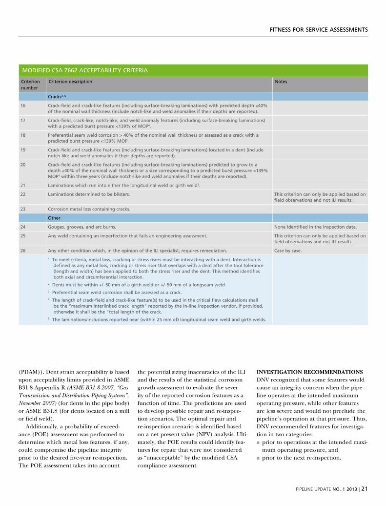
16 crack-field and crack-like features (including surface-breaking laminations) with predicted depth ≥40% of the nominal wall thickness (include notch-like and weld anomalies if their depths are reported).
17 crack-field, crack-like, notch-like, and weld anomaly features (including surface-breaking laminations) with a predicted burst pressure <139% of mOP4.
18 Preferential seam weld corrosion > 40% of the nominal wall thickness or assessed as a crack with a predicted burst pressure <139% mOP.
19 crack-field and crack-like features (including surface-breaking laminations) located in a dent (include notch-like and weld anomalies if their depths are reported).
20 crack-field and crack-like features (including surface-breaking laminations) predicted to grow to a depth ≥40% of the nominal wall thickness or a size corresponding to a predicted burst pressure <139% mOP4 within three years (include notch-like and weld anomalies if their depths are reported).
21 laminations which run into either the longitudinal weld or girth weld5.
22 laminations determined to be blisters. this criterion can only be applied based on field observations and not ili results.
23 corrosion metal loss containing cracks.
Other
24 gouges, grooves, and arc burns. None identified in the inspection data.
25 any weld containing an imperfection that fails an engineering assessment. this criterion can only be applied based on field observations and not ili results.
26 any other condition which, in the opinion of the ili specialist, requires remediation. case by case.
1 to meet criteria, metal loss, cracking or stress risers must be interacting with a dent. interaction is defined as any metal loss, cracking or stress riser that overlaps with a dent after the tool tolerance (length and width) has been applied to both the stress riser and the dent. this method identifies both axial and circumferential interaction.
2 Dents must be within +/–50 mm of a girth weld or +/–50 mm of a longseam weld.3 Preferential seam weld corrosion shall be assessed as a crack.4 the length of crack-field and crack-like feature(s) to be used in the critical flaw calculations shall
be the “maximum interlinked crack length” reported by the in-line inspection vendor, if provided, otherwise it shall be the “total length of the crack.
5 the laminations/inclusions reported near (within 25 mm of) longitudinal seam weld and girth welds.
(pdAm)). dent strain acceptability is based upon acceptability limits provided in Asme b31.8 Appendix r (ASME B31.8-2007, “Gas Transmission and Distribution Piping Systems”, November 2007) (for dents in the pipe body) or Asme b31.8 (for dents located on a mill or field weld).
Additionally, a probability of exceed-ance (poe) assessment was performed to determine which metal loss features, if any, could compromise the pipeline integrity prior to the desired five-year re-inspection. the poe assessment takes into account
the potential sizing inaccuracies of the ili and the results of the statistical corrosion growth assessment to evaluate the sever-ity of the reported corrosion features as a function of time. the predictions are used to develop possible repair and re-inspec-tion scenarios. the optimal repair and re-inspection scenario is identified based on a net present value (npv) analysis. ulti-mately, the poe results could identify fea-tures for repair that were not considered as “unacceptable” by the modified CsA compliance assessment.
InvesTIgATIOn reCOMMendATIOns dnv recognized that some features would cause an integrity concern when the pipe-line operates at the intended maximum operating pressure, while other features are less severe and would not preclude the pipeline’s operation at that pressure. thus, dnv recommended features for investiga-tion in two categories:■■ prior to operations at the intended maxi-mum operating pressure, and
■■ prior to the next re-inspection.
22 | pipeliNe upDate NO. 1 2013
›› comparison of in-line inspection magnetic flux leakage (mfl) signal data (previous survey vs. current survey) used to verify corrosion growth.
FitNess-FOr-service assessmeNts
‹‹ ultrasonic crack Detection (utcD) in-line inspection tool used to identify crack-like flaws.
Features that warrant investigation prior to the pressure increase include those that are predicted to have a depth >75% of the pipe nominal wall thickness or a predicted burst pressure <139% of the intended maximum operating pressure within the next three years. other unacceptable fea-tures were recommended for investigation prior to the pressure increase as well, if dnv determined they pose a considerable risk under those operating conditions (e.g., crack-like features or dents with relatively short calculated fatigue lives or dents with
high strain values). less severe features that do not warrant investigation prior to the pressure increase would be recom-mended for investigation prior to the next re-inspection if dnv determined they pose a low risk while the pipeline operates at the intended maximum operating pressure.
ACTIng On THe resulTs As dnv com-pletes the fitness-for-service assessments, trans-northern prepares and executes a repair/remediation program (based on dnv’s recommendations) to prepare the
pipelines for the return to service at 100% mop. however, before the pressure can be restored, trans-northern must formally make an application to the neb for remov-ing the pressure restriction. dnv’s fitness-for-service reports will be an integral part of the applications, as dnv has assisted many other operators in satisfying similar corrective action requirements. dnv has a favorable reputation with the neb as being a competent, world-class pipeline consultant.
current survey
previous survey
pipeliNe upDate NO. 1 2013 | 23
PiPeliNe cONstructiON
dnv-led joint industry project:
welding of field segmented induction bends and elbows
for pipeline constructionRecognizingtheneedtodevelopguidelinesfortheuseoffield-segmentedinductionbendsandelbowsforpipelineconstruction,SpectraEnergyorganizedajointindustryproject (Jip) that was conducted by DNV. the overall goal of the Jip was to develop
practical guidelines for using segmented induction bends and long-radius elbows for onshore pipeline construction, and to identify practices which should be avoided.
text: bIll bruCe, dnv
besides spectra, participation in the pro-ject included Alliance pipeline, kinder morgan, Centerpoint energy, nisource, transCanada, el paso, panhandle energy and williams. the sponsors agreed that sharing the project’s results was in the best interest of the industry and the general public.
the need to use segmented induction bends and elbows can arise for a variety of reasons during construction of new pipelines or during pipeline repair and maintenance activities. For example, bends having a tighter radius than can be accomplished by cold field bending may be required to accommodate abrupt directional changes. while some tight-radius directional changes can be accom-modated by ordering induction bends with specific bend angles, the bend angles required are not always known prior to construction.
the jip had two main objectives carried out in two phases:
1. to develop guidance regarding the spec-ification and purchase of segmentable induction bends and elbows
2. to develop guidance for field construc-tion practices
Final reports for both phases can be found at www.dnvusa.com/resources/reports.
in phase 1 of the work, the manu-facturing methods, capabilities, and limitations of induction bend and elbow manufacturers were evaluated during vis-its to manufacturing facilities. pertinent industry standards and related pipeline company specifications were reviewed. the information was summarized and used to develop examples of generic pur-chasing specifications for both segmenta-ble induction bends and manufactured elbows. Annotations in the specifications describe the source of key content and highlight content specifically related to segmentability.
in phase 2, optimal methods for map-ping, cutting, beveling, and transitioning induction bends and elbows were devel-oped. recommended practices for welding in the field and for a variety of related issues were also developed. the informa-tion was summarized and used to develop a generic specification for segmenting and welding of induction bends and elbows.
›› bill bruce, p.e., Director, welding & materials technology, DNV
phot
o: D
NV
24 | pipeliNe upDate NO. 1 2013
iNterNal cOrrOsiON health check
internal corrosion health check advised for liquid and
gas pipeline operatorsbased on escalating regulatory emphasis on internal corrosion management, pipeline operators would
be wise to anticipate increased oversight in this area. a look at recent history may provide clues on where new regulations are heading and insight on how to be prepared for the future changes.
text: rICHArd b. eCKerT, dnv
reprinted From mAteriAls perFormAnCe, deCember 2012, nACe internAtionAl
pipelines regulated under 49 CFr 192 and 195 must meet specific requirements when transporting potentially corrosive gas or liquids. in particular, operators must have adequate documentation to demonstrate that the pipeline is not in “corrosive” ser-vice, or that effective mitigative and pre-ventative measures are in place to address corrosive conditions. over the past twelve years, Advisory bulletins issued by the pipeline and hazardous materials safety Administration (phmsA) have repeatedly emphasized the need for pipeline opera-tors to conduct periodic reassessments of their internal corrosion programs.
neW rules On THe HOrIzOn An Advance notice of proposed rule-making (Anprm) was issued by phmsA in August, 2011, to solicit input on a
number of issues where new regulations are being considered for gas transmission pipelines. in regard to internal corrosion, phmsA is considering revising 49 CFr 192 subpart i to possibly include:■■ requiring periodic in-line inspection or sampling of accumulated liquids to
assure that internal corrosion is not occurring
■■ requiring additional measures to pre-vent internal corrosion in gas transmis-sion pipelines
■■ Changing the definition of corrosive gas to clarify that other constituents of a gas stream (e.g. water, carbon dioxide, sulfur and hydrogen sulfide) could make the gas stream corrosive
■■ prescribing corrosion control meas-ures with clearly defined conditions and appropriate mitigation efforts for high consequence areas (hCAs) and non-hCAs
■■ requiring a periodic analysis of the effectiveness of operator corrosion man-agement programs, which integrates information about Cp, coating anoma-lies, in-line inspection data, corrosion
›› richard b. eckert, principal engineer, internal corrosion management, DNV
pipeliNe upDate NO. 1 2013 | 25
phot
o: x
x
iNterNal cOrrOsiON health check
coupon data, corrosion inhibitor usage, analysis of corrosion products, environ-mental and soil data, and any other per-tinent information related to corrosion management
■■ requiring that operators periodically submit corrosion management perfor-mance metric data
the focus on data collection and integra-tion, and conducting regular assessments to evaluate internal corrosion threats and mitigation, is quite clear, based on the Anprm.
most recently the pipeline safety Act, signed into law on 3 january 2012, pro-vided enhanced authority to the dot, increased the maximum penalty for viola-tions, and required the dot to evalu-ate whether integrity management rules
should be expanded to cover non-hCA pipeline segments.
given the historical and current level of political and regulatory attention, pipeline operators’ integrity management require-ments can only be expected to increase. management of internal corrosion threat identification, prevention and mitigation, and risk assessments will clearly be an important part of the future compliance picture.
InTernAl COrrOsIOn “HeAlTH CHeCK” An internal corrosion “health check” (or audit) is a systematic review and assessment of the internal corrosion threats posed to a pipeline system, and the operator’s programs to monitor and mitigate those threats. the primary objec-tives of the health check are to ensure that
all internal corrosion threats are identi-fied and characterized, and to verify that adequate measures are in place to reduce the likelihood of pipeline failures result-ing from internal corrosion. the results of the iC health check can also be used to support the operator’s risk management and integrity management programs. An internal corrosion health check provides the formal assessment and documentation required to ensure that the threat of inter-nal corrosion is adequately considered, which also supports regulatory audits.
establishing a formal, documented process for periodic assessment of internal corrosion threats helps ensure consist-ency in the process and improves the reliability of the results. A documented process also makes subsequent assess-ments easier to perform, since data from
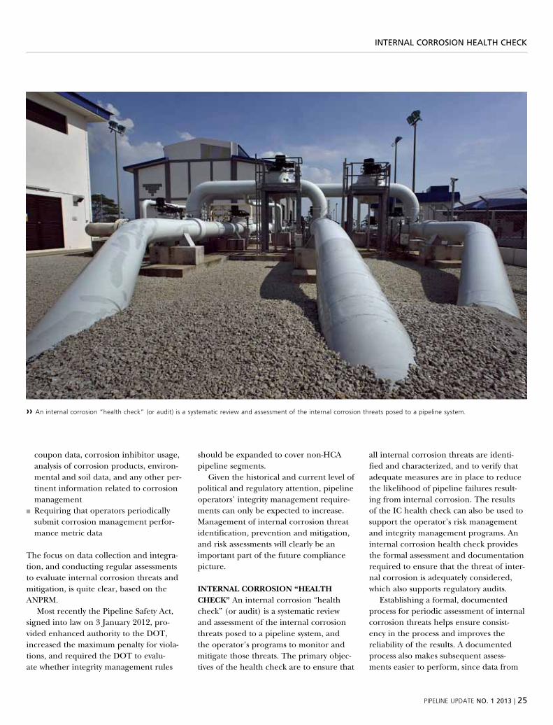
›› an internal corrosion “health check” (or audit) is a systematic review and assessment of the internal corrosion threats posed to a pipeline system.
phot
o: D
NV
26 | pipeliNe upDate NO. 1 2013
iNterNal cOrrOsiON health check
earlier assessments will be maintained in a functional format. the typical steps used in conducting an initial iC health check include:1. defining assets to be assessed2. documenting the design and operating
conditions3. Assessing the present internal corrosion
threats and their severity4. evaluating monitoring programs and
effectiveness5. evaluating mitigation programs and
effectiveness6. identifying program gaps 7. identifying continuous improvement
opportunities
the first step is fairly straightforward; the boundaries of the pipeline assets to be assessed are identified. this step is particu-larly important in a complex pipeline net-work, as it will help in later segmentation of the system based on specific corrosion threats.
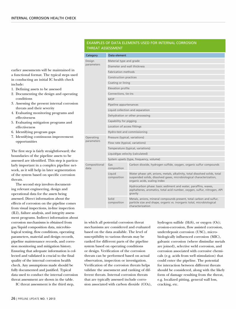
the second step involves document-ing relevant engineering, design and operational data for the assets being assessed. direct information about the effects of corrosion on the pipeline comes from visual inspections, in-line inspection (ili), failure analysis, and integrity assess-ment programs. indirect information about corrosion mechanisms is obtained from gas/liquid composition data, microbio-logical testing, flow conditions, operating parameters, material and design records, pipeline maintenance records, and corro-sion monitoring and mitigation history. ensuring that adequate information is col-lected and validated is crucial to the final quality of the internal corrosion health check. Any assumptions made should be fully documented and justified. typical data used to conduct the internal corrosion threat assessment are shown in the table.
iC threat assessment is the third step,
in which all potential corrosion threat mechanisms are considered and evaluated based on the data available. the level of susceptibility to various threats may be ranked for different parts of the pipeline system based on operating conditions or design. verification of the corrosion threats can be performed based on actual observation, inspection or investigation. verification of the corrosion threats helps validate the assessment and ranking of dif-ferent threats. internal corrosion threats that are typically assessed include corro-sion associated with carbon dioxide (Co2),
hydrogen sulfide (h2s), or oxygen (o2); erosion-corrosion, flow assisted corrosion, underdeposit corrosion (usC), micro-biologically influenced corrosion (miC), galvanic corrosion (where dissimilar metals are joined), selective weld corrosion, and corrosion associated with corrosive chemi-cals (e.g. acids from well stimulation) that could enter the pipeline. the potential for interaction between different threats should be considered, along with the likely form of damage resulting from the threat, e.g. localized pitting, general wall loss, cracking, etc.
examPles OF Data elemeNts useD FOr iNterNal cOrrOsiON threat assessmeNt
category Data element
Design parameters
material type and grade
Diameter and wall thickness
Fabrication methods
construction practices
coating or lining
elevation profile
connections, tie-ins
mOP
Pipeline appurtenances
liquid collection and separation
Dehydration or other processing
capability for pigging
location of access fittings
hydro-test and commissioning
Operating parameters
Pressure (typical, variations)
Flow rate (typical, variations)
temperature (typical, variations)
liquid/gas velocity (calculated)
system upsets (type, frequency, volume)
compositional data
gas composition
carbon dioxide, hydrogen sulfide, oxygen, organic sulfur compounds
liquid composition
Water phase: ph, anions, metals, alkalinity, total dissolved solids, total suspended solids, dissolved gases, microbiological characterization, organic acids, scaling index
hydrocarbon phase: basic sediment and water, paraffins, waxes, asphaltenes, aromatics, total acid number, oxygen, sulfur, nitrogen, aPi gravity
solid composition
metals, anions, mineral compounds present, total carbon and sulfur, particle size and shape, organic vs. inorganic total, microbiological characterization
pipeliNe upDate NO. 1 2013 | 27
iNterNal cOrrOsiON health check
in the fourth and fifth steps of the iC health check. the corrosion monitoring and mitigation programs are evaluated and procedures verified. the purpose of these steps is to ensure that all internal corrosion threats identified in the third step are being adequately mitigated and that the monitoring program is appropri-ate to detect those threats. For example, if underdeposit corrosion was identified as a threat, monitoring using a weight loss coupon inserted directly into the prod-uct stream may not determine whether that threat is being controlled since it is unlikely that deposits will accumulate on the coupon. likewise, if maintenance pigging is being used to remove solids to reduce the likelihood of underdeposit cor-rosion, the effectiveness of that mitigation must be measured, such as by monitoring the amount of solids recovered from each pig run.
the sixth step is where data and/or knowledge gaps in the internal corrosion management program are identified. per-haps more operating condition data are needed to ensure that liquid upsets are not entering a pipeline or better monitor-ing is needed to detect water upsets from a producer. Filling these gaps will improve the performance of the internal corrosion management program, reduce the impact of internal corrosion on the pipeline sys-tem, and increase the reliability of future threat assessments.
in the final step of the iC health check, the results of the assessment are examined to identify ways to continu-ously improve the quality of the internal corrosion management process. Asme b31.8s section 9.6 speaks to the need for continuous improvement in any pipeline integrity management program, based on the analysis of audit results and key performance indicators. the iC health check promotes improved management
of the internal corrosion integrity threat by providing important feedback to the imp process.
PerIOdIC reAssessMenT buIlds COnfIdenCe Following completion of the standardized process for conducting the iC health check, the operator can produce a report documenting the threat assessment results and the effectiveness of the existing monitoring and mitigation programs. Annual or periodic reassess-ments require less time and effort after the initial health check is performed.
the steps for conducting a periodic reassessment are similar; however, once the baseline information is established, the re-evaluation primarily looks for con-ditions that have changed since the last health check. this approach would be con-sistent with the guidance given in previous phmsA Advisory bulletins. key perfor-mance indicators can also be drawn from and based upon the internal corrosion management actions identified for various threats in the iC health check.
while the iC health check does not necessarily need to include risk assess-ment (i.e. considering consequences), the results of the health check can certainly feed into an operator’s risk management program. where risk encompasses both likelihood and consequence, the iC health check may only consider likelihood and reducing likelihood of damage leading to a release.
Conducting an iC health check on a regular basis helps an operator manage the threat of internal corrosion by provid-ing several benefits. direct benefits from thoroughly and adequately managing internal corrosion include:■■ A clear understanding of the internal corrosion threats for each asset
■■ the ability to discern the potential for threat interaction
■■ Accurate threat information for use in risk models
■■ selection of effective and appropriate monitoring technologies
■■ the ability to optimize mitigation program; increasing effectiveness and reducing waste
■■ An auditable process with ability to detect creeping change.
benefITs beYOnd COMPlIAnCe the need to manage the threat of internal corrosion is not only driven by regulatory compliance. Assuring that the threat of internal corrosion is adequately addressed also helps reduce the business risk to which hazardous liquid and gas pipe-line operators are continually exposed. A review of pipeline accident statistics will quickly reveal that internal corrosion is a real threat – resulting in significant property damage, loss of service, envi-ronmental contamination and personal injury every year. operators are liable for cleanup costs, regulatory penalties, and litigation expense; they may face criminal prosecution, congressional hearings and loss of reputation. the costs associated with pipeline leaks or spills can run to billions of dollars. based on the potential business risk, internal corrosion cannot be dismissed as a threat simply because a pipeline has not leaked or ruptured in the past.
while the coming regulatory changes affecting the pipeline industry remain to be seen, some observations can be made from historical regulatory advisories and from the rulemaking currently under consideration. operators who are actively understanding and managing their integ-rity threats, following a clear process for assessing the performance of mitigative and preventive measures and documenting the results, are certain to be better pre-pared for the future.
28 | pipeliNe upDate NO. 1 2013
iNtegrity maNagemeNt
integrity management of pipelines subject to stress
corrosion crackingstress corrosion cracking can be a serious threat to the integrity of natural gas and petroleum pipelines. the pipeline industry responded to this threat by performing a
comprehensive research program to determine the cause(s) of the failures and investigate various techniques for preventing future failures. a relatively concise list of discoveries
has had a measurable impact on mitigation of the stress corrosion cracking threat.
text: JOHn A. beAvers, dnv
starting with the first recognized stress cor-rosion cracking failure in 1965, the inter-granular form of cracking (also known as high-ph sCC) was investigated to identify the causative agent and the controlling metallurgical, environmental, and stress related factors. in the 1980s, a second, transgranular form of stress corrosion cracking (near neutral ph sCC) was dis-covered in Canada, resulting in a similar scope of research activities designed to develop mitigation methods for this form of cracking. the information developed in these research programs has been incorpo-rated into pipeline integrity management programs.
THree TeCHnIQues there are three common techniques used for manage-ment of the integrity of pipelines subject to stress corrosion cracking and other time dependent threats; hydrostatic testing,
direct assessment, and in-line inspection (ili). directly following the initial stress corrosion cracking failures of gas transmis-sion pipelines in the 1960s, hydrostatic testing was the primary tool used to con-firm the integrity of the affected pipelines and prevent additional failures. the pipelines were pressure tested with water at pressures significantly higher than the operating pressure in order to remove any near critical flaws. this technique has a number of limitations. very few, if any, stress corrosion cracking flaws are removed, and the pipeline must be taken out of service for testing. in dry climates, obtaining adequate sources of water can be a challenge, while freezing of the water can be an issue in winter months or north-ern climates. For liquid petroleum pipe-lines, the water must be extensively treated prior to discharge back into the environ-ment. there also is a finite probability of a
phenomenon known as a pressure reversal occurring, where the failure pressure after a hydrostatic test is lower than the maxi-mum test pressure, as a result of subcritical crack growth during the hydrostatic test.
AlTernATIves TO HYdrOsTATIC TesTIng because of these limitations, there has been significant interest within the pipeline community in the develop-ment of alternatives to hydrostatic testing. one alternative is sCC direct Assess-ment (sCCdA). the first recommended practice for sCCdA was issued in 2004 (nACe standard rp0204-2004). sCCdA is a structured process intended to assist pipeline companies in assessing the extent of stress corrosion cracking on buried pipelines, thus contributing to their efforts to improve safety by reducing the impact of external stress corrosion cracking on pipeline integrity. the term is somewhat
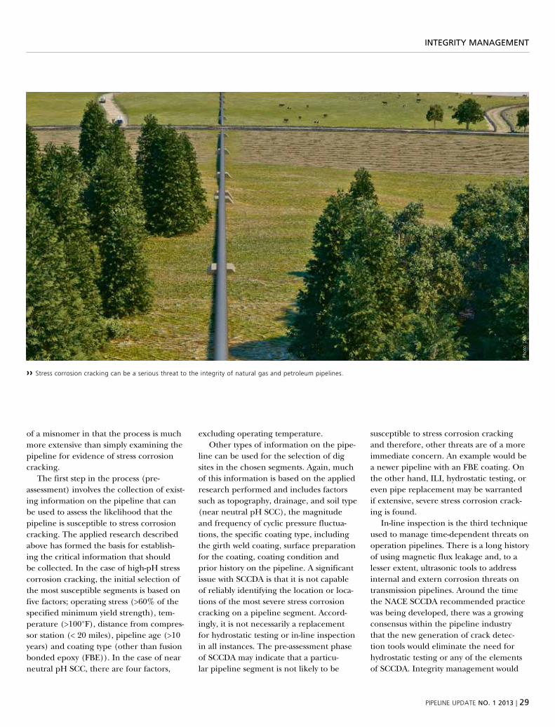
pipeliNe upDate NO. 1 2013 | 29
iNtegrity maNagemeNt
of a misnomer in that the process is much more extensive than simply examining the pipeline for evidence of stress corrosion cracking.
the first step in the process (pre-assessment) involves the collection of exist-ing information on the pipeline that can be used to assess the likelihood that the pipeline is susceptible to stress corrosion cracking. the applied research described above has formed the basis for establish-ing the critical information that should be collected. in the case of high-ph stress corrosion cracking, the initial selection of the most susceptible segments is based on five factors; operating stress (>60% of the specified minimum yield strength), tem-perature (>100°F), distance from compres-sor station (< 20 miles), pipeline age (>10 years) and coating type (other than fusion bonded epoxy (Fbe)). in the case of near neutral ph sCC, there are four factors,
excluding operating temperature. other types of information on the pipe-
line can be used for the selection of dig sites in the chosen segments. Again, much of this information is based on the applied research performed and includes factors such as topography, drainage, and soil type (near neutral ph sCC), the magnitude and frequency of cyclic pressure fluctua-tions, the specific coating type, including the girth weld coating, surface preparation for the coating, coating condition and prior history on the pipeline. A significant issue with sCCdA is that it is not capable of reliably identifying the location or loca-tions of the most severe stress corrosion cracking on a pipeline segment. Accord-ingly, it is not necessarily a replacement for hydrostatic testing or in-line inspection in all instances. the pre-assessment phase of sCCdA may indicate that a particu-lar pipeline segment is not likely to be
susceptible to stress corrosion cracking and therefore, other threats are of a more immediate concern. An example would be a newer pipeline with an Fbe coating. on the other hand, ili, hydrostatic testing, or even pipe replacement may be warranted if extensive, severe stress corrosion crack-ing is found.
in-line inspection is the third technique used to manage time-dependent threats on operation pipelines. there is a long history of using magnetic flux leakage and, to a lesser extent, ultrasonic tools to address internal and extern corrosion threats on transmission pipelines. Around the time the nACe sCCdA recommended practice was being developed, there was a growing consensus within the pipeline industry that the new generation of crack detec-tion tools would eliminate the need for hydrostatic testing or any of the elements of sCCdA. integrity management would
›› stress corrosion cracking can be a serious threat to the integrity of natural gas and petroleum pipelines.
phot
o: D
NV
30 | pipeliNe upDate NO. 1 2013
iNtegrity maNagemeNt
consist of four elements; find the cracks, size the cracks, assess the cracks and repair the cracks.
unfortunately, the experience with crack detection tools has not been as desir-able as had been hoped. over the past few years, there have been at least two service failures of pipelines in which the opera-tors were using crack detection tools for integrity management. in the case of one failure in Carmichael ms, the cause and contributing factors could not be con-firmed because of extensive fire damage to the failed pipe. A portion of the fracture did propagate along the seam weld and the pipeline had a history of seam weld defects. the pipe section that contained the failure also had been previously hydro-statically tested at a pressure much higher than the failure pressure. this informa-tion, taken together, suggests that a likely cause of failure was the growth of a seam weld defect in service. in the second case, a failure near marshall mi, there was evi-dence that fatigue cracks grew from a colo-ny of pre-existing stress corrosion cracks.
ACCurACY Of CrACK sIzIng the prob-lem with the current generation of crack detection tools appears to be related to the accuracy of crack sizing. the tools are very good at finding crack-like features, and the length accuracy for the features also typically is good. the problem is the depth accuracy. the feature calls are usu-ally binned by depth into several depths; e.g. <15% of wall thickness, 15–30% of wall thickness, 30–45% of wall thickness and >45% of wall thickness. Currently, there does not appear to be sufficient accuracy in the binning process for integrity man-agement purposes. the failure pressures in pipelines containing cracks are much more sensitive to depth than to length of the flaws. the problem could be related to the precision and accuracy of the tool, or the analytical process for analyzing the tool data.
because of these sizing issues, pipe-line operators are sometimes required to
perform a confirmatory hydrostatic test on portions of their system to demonstrate the performance of the crack detection tool. in some cases, pipeline operators also may be faced with a situation where a large number (thousands) of features are found on a segment of a pipeline. the elements of sCCdA can then be used, in conjunc-tion with the standard crack sizing, to identify which feature are most likely to be an integrity threat and should be excavat-ed. these elements are also used to prior-itize pipeline systems for in-line inspection. the point is that fundamental understand-ing of the sCC process, developed through applied research, is still of significant value in integrity management.
As previously described, the informa-tion developed in the research programs is also used by pipeline companies to operate their pipelines in a way that reduces the risk of stress corrosion cracking failures. where there is a risk of high ph sCC, after-coolers are installed at compressor stations to reduce outlet temperatures. operators may control pressure fluctua-tions to reduce the risk of both forms of stress corrosion cracking. Cathodic protec-tion systems are enhanced, monitored, and maintained to keep the pipe to soil potential out of the potential range for cracking. Finally, this research information is used by prudent operators in construc-tion activities to reduce the risk of stress corrosion cracking in the future. near white surface preparation procedures and coatings, such as Fbe, are selected to mini-mize stress corrosion cracking initiation. girth weld coating systems are selected to minimize shielding. the pipeline systems are designed to minimize operating tem-peratures and cyclic pressures.
fuTure Trends the detection and siz-ing capabilities of the crack detection tools will undoubtedly improve, but there will always be a need for elements of sCCdA, developed through applied research, to prioritize pipeline segments for inspection. depending on the pace of improvements
in the precision and accuracy of these systems, there may continue to be a neces-sity, for the near future, to use elements of sCCdA to help identify which features are most likely to be sCC threats.
Although not discussed in this article, there are other stress corrosion cracking threats to operating pipelines. ethanol is used in almost all of the gasoline con-sumed in the united states as an oxygenat-ing agent and octane booster. the current blend limit is 10% ethanol, but this may be increased to 15% in the near future. denatured fuel grade ethanol is transport-ed to terminals where it is blended with gasoline. pipelines are the most efficient method to transport the ethanol but the threat of internal stress corrosion cracking has prevented general transportation via pipelines. research is ongoing to address this threat.
A new internal stress corrosion cracking threat from alcohol was recently identi-fied. methanol is sometimes used as a dry-ing agent for pipelines directly following hydrostatic testing. in northern climates, neat methanol is also sometimes used for hydrostatic testing to avoid freezing. there is growing evidence that this methanol has caused internal stress corrosion cracking of some pipelines; research is ongoing to address this threat.

pipeliNe upDate NO. 1 2013 | 31
Nace iNterNatiONal’s sPeller aWarD
dr john beavers to receive nACe international’s
speller Awardwe are pleased to announce that DNV’s Dr John beavers is to be awarded the
coveted frank Newman speller award at Nace international’s annual conference in orlando, florida in march. the award is presented by Nace international annually to
an individual for significant contributions in the field of corrosion engineering.
text: CHrIs POllArd, dnv
dr beavers currently holds the position of director, Failure Analysis and Chief sci-entist with dnv’s business unit located in dublin, ohio. he has played an integral role in the post-failure investigation of a some of the most prominent pipeline failures in north America over the past quarter century.
his research endeavors are vast, but he is particularly known for his advancements in the study of stress corrosion cracking
(sCC), both in near-neutral ph sCC and high ph sCC. his work in the latter led to the development of nACe’s direct Assessment standard for sCC (sCCdA). his recent breakthrough work has dealt with the research of sCC in ethanol environments.
dr beavers has held various committee positions with nACe in his more than 35 years in the corrosion control industry. in 2002, he was recognized by pipeline
research Council international (prCi) with its distinguished researcher Award. in 2004, he was recognized as a nACe Fellow. prior to joining dnv, he was a research scientist for battelle memorial institute. he obtained his undergraduate and graduate degrees in metallurgy from the university of illinois.
we salute dr beavers for his many con-tributions to the industry we serve.
›› Dr John a. beavers is to be awarded the coveted frank Newman speller award at Nace international’s annual conference in orlando, florida in march.
phot
o: D
NV
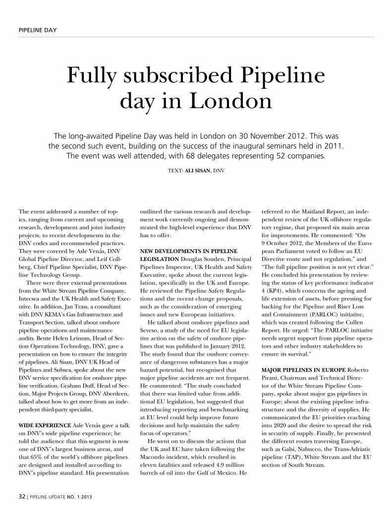
32 | pipeliNe upDate NO. 1 2013
PiPeliNe Day
Fully subscribed pipeline day in london
the long-awaited pipeline Day was held in london on 30 November 2012. this was the second such event, building on the success of the inaugural seminars held in 2011.
the event was well attended, with 68 delegates representing 52 companies.
text: AlI sIsAn, dnv
the event addressed a number of top-ics, ranging from current and upcoming research, development and joint industry projects, to recent developments in the dnv codes and recommended practices. they were covered by Asle venås, dnv global pipeline director, and leif Coll-berg, Chief pipeline specialist, dnv pipe-line technology group.
there were three external presentations from the white stream pipeline Company, intecsea and the uk health and safety exec-utive. in addition, jan trass, a consultant with dnv kemA’s gas infrastructure and transport section, talked about onshore pipeline operations and main tenance audits. bente helen leinum, head of sec-tion operations technology, dnv, gave a presentation on how to ensure the integrity of pipelines. Ali sisan, dnv uk head of pipelines and subsea, spoke about the new dnv service specification for onshore pipe-line verification. graham duff, head of sec-tion, major projects group, dnv Aberdeen, talked about how to get more from an inde-pendent third-party specialist.
WIde exPerIenCe Asle venås gave a talk on dnv’s wide pipeline experience; he told the audience that this segment is now one of dnv’s largest business areas, and that 65% of the world’s offshore pipelines are designed and installed according to dnv’s pipeline standard. his presentation
outlined the various research and develop-ment work currently ongoing and demon-strated the high-level experience that dnv has to offer.
neW develOPMenTs In PIPelIne legIslATIOn douglas souden, principal pipelines inspector, uk health and safety executive, spoke about the current legis-lation, specifically in the uk and europe. he reviewed the pipeline safety regula-tions and the recent change proposals, such as the consideration of emerging issues and new european initiatives.
he talked about onshore pipelines and seveso, a study of the need for eu legisla-tive action on the safety of onshore pipe-lines that was published in january 2012. the study found that the onshore convey-ance of dangerous substances has a major hazard potential, but recognised that major pipeline accidents are not frequent. he commented: “the study concluded that there was limited value from addi-tional eu legislation, but suggested that introducing reporting and benchmarking at eu level could help improve future decisions and help maintain the safety focus of operators.”
he went on to discuss the actions that the uk and eC have taken following the macondo incident, which resulted in eleven fatalities and released 4.9 million barrels of oil into the gulf of mexico. he
referred to the maitland report, an inde-pendent review of the uk offshore regula-tory regime, that proposed six main areas for improvements. he commented: “on 9 october 2012, the members of the euro-pean parliament voted to follow an eu directive route and not regulation,” and “the full pipeline position is not yet clear.” he concluded his presentation by review-ing the status of key performance indicator 4 (kp4), which concerns the ageing and life extension of assets, before pressing for backing for the pipeline and riser loss and Containment (pArloC) initiative, which was created following the Cullen report. he urged: “the pArloC initiative needs urgent support from pipeline opera-tors and other industry stakeholders to ensure its survival.”
MAJOr PIPelInes In eurOPe roberto pirani, Chairman and technical direc-tor of the white stream pipeline Com-pany, spoke about major gas pipelines in europe; about the existing pipeline infra-structure and the diversity of supplies. he communicated the eu priorities reaching into 2020 and the desire to spread the risk in security of supply. Finally, he presented the different routes traversing europe, such as galsi, nabucco, the trans-Adriatic pipeline (tAp), white stream and the eu section of south stream.
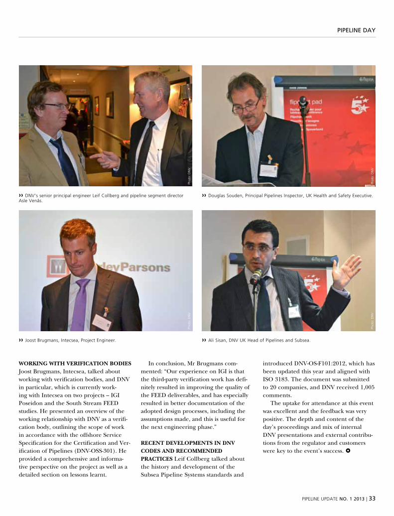
pipeliNe upDate NO. 1 2013 | 33
PiPeliNe Day
WOrKIng WITH verIfICATIOn bOdIes joost brugmans, intecsea, talked about working with verification bodies, and dnv in particular, which is currently work-ing with intecsea on two projects – igi poseidon and the south stream Feed studies. he presented an overview of the working relationship with dnv as a verifi-cation body, outlining the scope of work in accordance with the offshore service specification for the Certification and ver-ification of pipelines (dnv-oss-301). he provided a comprehensive and informa-tive perspective on the project as well as a detailed section on lessons learnt.
in conclusion, mr brugmans com-mented: “our experience on igi is that the third-party verification work has defi-nitely resulted in improving the quality of the Feed deliverables, and has especially resulted in better documentation of the adopted design processes, including the assumptions made, and this is useful for the next engineering phase.”
reCenT develOPMenTs In dnv COdes And reCOMMended PrACTICes leif Collberg talked about the history and development of the subsea pipeline systems standards and
introduced dnv-os-F101:2012, which has been updated this year and aligned with iso 3183. the document was submitted to 20 companies, and dnv received 1,005 comments.
the uptake for attendance at this event was excellent and the feedback was very positive. the depth and content of the day’s proceedings and mix of internal dnv presentations and external contribu-tions from the regulator and customers were key to the event’s success.
›› DNV’s senior principal engineer leif collberg and pipeline segment director asle Venås.
›› Joost brugmans, intecsea, project engineer.
›› Douglas souden, principal pipelines inspector, uk health and safety executive.
›› ali sisan, DNV uk head of pipelines and subsea.
phot
o: D
NV
phot
o: D
NV
phot
o: D
NV
phot
o: D
NV
34 | pipeliNe upDate NO. 1 2013
JiP uPDate
update on dnv-managed joint industry projects relevant for pipelines
the pipeline industry is constantly looking into cost-effective solutions. in addition, pushing into the new energy frontier poses great challenges for pipeline systems. as a pipeline technology leader, DNV is committed to continuously supporting the industry
and a range of r&D and Jips are currently taking the industry further ahead.
text: Asle venås, dnv
dnv invests 6–7% of its revenue in r&d and a large proportion of this is spent on pipeline-related projects. dnv is well suited for pipeline r&d as we have run many jips, written many standards and guidelines, have a very highly educated and experienced staff covering all relevant pipeline disciplines and lots of experience from challenging pipeline projects all over the globe. we also have four laboratories to do associated experiments and testing.
our laboratories are located in:■■ høvik, norway: large-size – full-scale test-ing laboratory
■■ bergen, norway: large-size – full-scale corrosion laboratory testing
■■ singapore: large-size – full-scale testing laboratory
■■ Columbus, ohio, usA: corrosion and h2s testing laboratory
some of the investment is in internally funded pipeline r&d projects: eleven such projects have recently been complet-ed and one is ongoing.
Completed:■■ pipelines for the future – pipeline tech-nology for the next 10 – 15 years
■■ x-stream – cost-effective solution for a deepwater gas pipeline
■■ slipipe – solution for hpht pipelines■■ Floatpipe – Floating pipelines for deep water and challenging seabeds
■■ residual stress/strain for pipeline girth welds under high strain (measuring residual stress)
■■ developing a method for the sent test (Ctod testing – under pure tension) for sour service
■■ update of dnv-rp-106 – Factory-applied external coating
■■ update of dnv-rp-102 – Field joint coating and field repair of linepipe coating
■■ development of Aut workmanship style acceptance criteria
■■ development of rp for Aut system qualification
■■ update of dnv-os-F101 – offshore standard for pipelines
ongoing: ■■ standard for verification of onshore pipelines
however, dnv prefers to work together with the industry and our main investment in pipeline r&d is through jips (joint industry projects). during the past few years, we have seen an increase in industry requests to us to initiate and participate in pipeline-related jips.
r&d work through jips has many advantages. Apart from saving costs through sharing them, more experience is put on the table. the sponsors can influence the scope of the work and all sponsors obtain all the data and results gathered through the jips. normally, the jips result in a guideline that is confiden-tial to the partners and each partner is free to use it in their normal business. the confidentiality period is set by the steering committee (witch consists of one member per paying sponsor). After the confidenti-ality period, dnv sometimes converts the guideline into a recommended practice or a pipeline standard. however, all data, reports and results from the jip will be confidential to the sponsors only.
with the increased focus on jips, dnv will:■■ improve on utilising the best resources in the pipeline industry – this also includes subcontracting some work to other companies, and
■■ professionalise its project management, including closer contact with the spon-sors and shorter execution times
dnv has recently completed, is currently running or is planning 31 pipeline-related joint industry projects:

pipeliNe upDate NO. 1 2013 | 35
JiP uPDate
sIx reCenTlY COMPleTed JIPs■■ hipps system design ■■ ice pipe – Arctic pipelines ■■ spiral welded pipes for offshore use – phases 1 and 2 completed
■■ Clad and liner pipe – phases 1–3■■ on-bottom stability design of small diameter, submarine umbilicals and cables
■■ treatment of residual stress in the eCA of pipeline girth welds under high plas-tic deformation
eleven OngOIng JIPs■■ Co2 pipelines, phase 2 ■■ pre-commissioning of pipelines ■■ pipeline integrity management (includ-ing update of dnv rp-116), phase 2
■■ hpht pipelines (merger of hotpipe and safebuck)
■■ development of guideline for horizon-tal directional drilling (hdd)
■■ development of guidelines for eCA in sour service
■■ design of rigid spools■■ Fatigue of girth welds with defects ■■ Corroded pipes (incl. update of dnv-rp-101)
■■ effect of reeling on sour service performance
■■ on-bottom stability design of submarine umbilicals and cables
14 PlAnned JIPs■■ spiral welded pipes for offshore use – phase 3
■■ Clad and liner pipe – phase 4■■ Assessment of pipeline components for offshore pipelines
■■ pipeline concrete coatings design
■■ qualification of x-80 pipes for sour ser-vice applications
■■ reliability-based fracture mechanics approach for pipeline girth welds
■■ Free-span assessment of pipelines in nar-row trench
■■ installation design and analysis■■ Cp insulation coupling for pipelines transporting electrical conductive liquids
■■ local brittle zones■■ risk assessment of pipeline protection■■ study collapse of pipelines with d/t < 15■■ Anchor pipeline interaction■■ recommended practice for pipe-in-pipe concept
several of our ongoing and all our planned jips are open for more sponsors. interested companies can contact Asle venås at [email protected]
phot
o: D
NV

globalpresence
DNV is a global provider of services for managing risk, helping customers to safely and responsibly improve their business performance. DNV is an independent foundation with presence in more than 100 countries.