picoflow - istec international
TRANSCRIPT

ENO
pera
ting
Inst
ruct
ions
PicoFlowMonitoring of solidsfor small solid / air ratios
SWR engineering Messtechnik GmbH PART OF THE ENVIRONNEMENT S.A GROUP
Superiorwith
Solids

Superiorwith
Solids
CONTENTS Page
1. System overview . . . . . . . . . . . . . . . . . . . . . . . . . . . . . . . . . . . . . . . . . . . . . . . . . . . . . . . . . . . . . . . . . . . . . . . 3
2. Function . . . . . . . . . . . . . . . . . . . . . . . . . . . . . . . . . . . . . . . . . . . . . . . . . . . . . . . . . . . . . . . . . . . . . . . . . . . . . . 4
3. Safety . . . . . . . . . . . . . . . . . . . . . . . . . . . . . . . . . . . . . . . . . . . . . . . . . . . . . . . . . . . . . . . . . . . . . . . . . . . . . . . . 5
3.1 Normal use . . . . . . . . . . . . . . . . . . . . . . . . . . . . . . . . . . . . . . . . . . . . . . . . . . . . . . . . . . . . . . . . . . . . . . . 5
3.2 Identification of hazards . . . . . . . . . . . . . . . . . . . . . . . . . . . . . . . . . . . . . . . . . . . . . . . . . . . . . . . . . . . . 5
3.3 Operational safety . . . . . . . . . . . . . . . . . . . . . . . . . . . . . . . . . . . . . . . . . . . . . . . . . . . . . . . . . . . . . . . . . . 5
3.4 Technical statement . . . . . . . . . . . . . . . . . . . . . . . . . . . . . . . . . . . . . . . . . . . . . . . . . . . . . . . . . . . . . . . . 5
4. Mounting and installation . . . . . . . . . . . . . . . . . . . . . . . . . . . . . . . . . . . . . . . . . . . . . . . . . . . . . . . . . . . . . . 6
4.1 Delivery range . . . . . . . . . . . . . . . . . . . . . . . . . . . . . . . . . . . . . . . . . . . . . . . . . . . . . . . . . . . . . . . . . . . . . 6
4.2 Auxiliary . . . . . . . . . . . . . . . . . . . . . . . . . . . . . . . . . . . . . . . . . . . . . . . . . . . . . . . . . . . . . . . . . . . . . . . . . . 6
4.3 Mounting of the sensor . . . . . . . . . . . . . . . . . . . . . . . . . . . . . . . . . . . . . . . . . . . . . . . . . . . . . . . . . . . . . 6
4.4 Mounting the transmitter . . . . . . . . . . . . . . . . . . . . . . . . . . . . . . . . . . . . . . . . . . . . . . . . . . . . . . . . . . . 8
4.5 Use in hazardous areas . . . . . . . . . . . . . . . . . . . . . . . . . . . . . . . . . . . . . . . . . . . . . . . . . . . . . . . . . . . . 10
5. Electrical connection . . . . . . . . . . . . . . . . . . . . . . . . . . . . . . . . . . . . . . . . . . . . . . . . . . . . . . . . . . . . . . . . . . 11
5.1 DIN rail terminal layout . . . . . . . . . . . . . . . . . . . . . . . . . . . . . . . . . . . . . . . . . . . . . . . . . . . . . . . . . . . . 11
5.2 Field housing terminal layout . . . . . . . . . . . . . . . . . . . . . . . . . . . . . . . . . . . . . . . . . . . . . . . . . . . . . . . 12
5.3 C3-box terminal layout . . . . . . . . . . . . . . . . . . . . . . . . . . . . . . . . . . . . . . . . . . . . . . . . . . . . . . . . . . . . . 13
6. Operator interface . . . . . . . . . . . . . . . . . . . . . . . . . . . . . . . . . . . . . . . . . . . . . . . . . . . . . . . . . . . . . . . . . . . . 14
6.1 Differences between the DIN rail and field housing transmitter . . . . . . . . . . . . . . . . . . . . . . . . . . 14
6.2 Display . . . . . . . . . . . . . . . . . . . . . . . . . . . . . . . . . . . . . . . . . . . . . . . . . . . . . . . . . . . . . . . . . . . . . . . . . . 15
6.3 PC interface . . . . . . . . . . . . . . . . . . . . . . . . . . . . . . . . . . . . . . . . . . . . . . . . . . . . . . . . . . . . . . . . . . . . . 16
6.4 One or more sensor system . . . . . . . . . . . . . . . . . . . . . . . . . . . . . . . . . . . . . . . . . . . . . . . . . . . . . . . . . 18
6.5 Menu structure . . . . . . . . . . . . . . . . . . . . . . . . . . . . . . . . . . . . . . . . . . . . . . . . . . . . . . . . . . . . . . . . . . . 20
7. Start-up procedure . . . . . . . . . . . . . . . . . . . . . . . . . . . . . . . . . . . . . . . . . . . . . . . . . . . . . . . . . . . . . . . . . . . 28
7.1 Basic start-up . . . . . . . . . . . . . . . . . . . . . . . . . . . . . . . . . . . . . . . . . . . . . . . . . . . . . . . . . . . . . . . . . . . . 28
7.2 Adjusting the measurement values . . . . . . . . . . . . . . . . . . . . . . . . . . . . . . . . . . . . . . . . . . . . . . . . . . 28
7.3 Error signalling . . . . . . . . . . . . . . . . . . . . . . . . . . . . . . . . . . . . . . . . . . . . . . . . . . . . . . . . . . . . . . . . . . . 29
7.4 Compatibility . . . . . . . . . . . . . . . . . . . . . . . . . . . . . . . . . . . . . . . . . . . . . . . . . . . . . . . . . . . . . . . . . . . . . 29
8. Connection examples . . . . . . . . . . . . . . . . . . . . . . . . . . . . . . . . . . . . . . . . . . . . . . . . . . . . . . . . . . . . . . . . . 30
8.1 Digital input . . . . . . . . . . . . . . . . . . . . . . . . . . . . . . . . . . . . . . . . . . . . . . . . . . . . . . . . . . . . . . . . . . . . . 30
8.2 Impulse output . . . . . . . . . . . . . . . . . . . . . . . . . . . . . . . . . . . . . . . . . . . . . . . . . . . . . . . . . . . . . . . . . . . 30
9. Maintenance . . . . . . . . . . . . . . . . . . . . . . . . . . . . . . . . . . . . . . . . . . . . . . . . . . . . . . . . . . . . . . . . . . . . . . . . . 31
10. Warranty . . . . . . . . . . . . . . . . . . . . . . . . . . . . . . . . . . . . . . . . . . . . . . . . . . . . . . . . . . . . . . . . . . . . . . . . . . . . 31
11. Troubleshooting . . . . . . . . . . . . . . . . . . . . . . . . . . . . . . . . . . . . . . . . . . . . . . . . . . . . . . . . . . . . . . . . . . . . . . 31
12. Technical data . . . . . . . . . . . . . . . . . . . . . . . . . . . . . . . . . . . . . . . . . . . . . . . . . . . . . . . . . . . . . . . . . . . . . . . 32
Superiorwith
Solids
Sensor
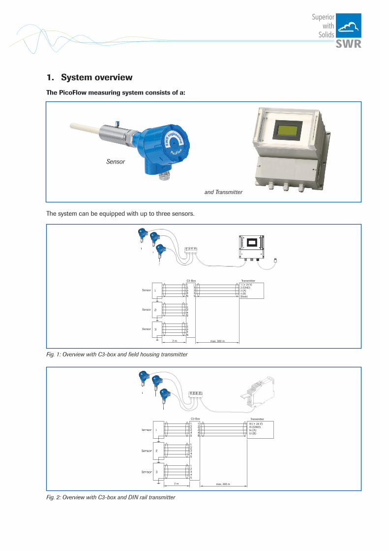
1. System overview
The PicoFlow measuring system consists of a:
and Transmitter
TransmitterC3-Box
Sensor
Sensor
Sensor
2 m max. 300 m
1 (+ 24 V)2 (GND)3 (A)4 (B)Shield
The system can be equipped with up to three sensors.
Fig. 1: Overview with C3-box and fi eld housing transmitter
Fig. 2: Overview with C3-box and DIN rail transmitter
TransmitterC3-Box
2 m max. 300 m
16 (+ 24 V)15 (GND)14 (A)13 (B)
Superiorwith
Solids
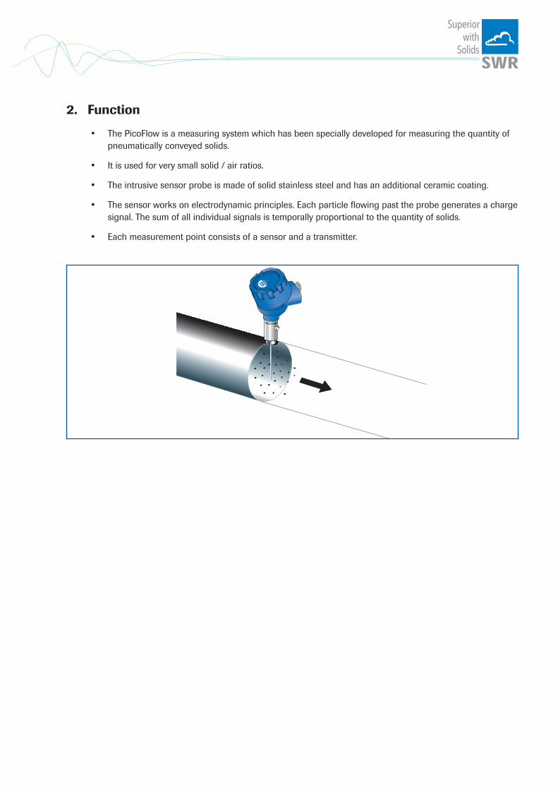
2. Function
• The PicoFlow is a measuring system which has been specially developed for measuring the quantity of pneumatically conveyed solids.
• It is used for very small solid / air ratios.
• The intrusive sensor probe is made of solid stainless steel and has an additional ceramic coating.
• The sensor works on electrodynamic principles. Each particle flowing past the probe generates a charge signal. The sum of all individual signals is temporally proportional to the quantity of solids.
• Each measurement point consists of a sensor and a transmitter.

Superiorwith
Solids
3. Safety
The PicoFlow was designed, built and tested for safety and is shipped in this condition. Components within the supplied system could be hazardous if not unpacked, installed, connected and commissioned by authorised qualified persons. All operating instructions must be read, and understood, before handling the system. Failure to do so will cause the warranty to be revoked.
3.1 Normal use • The measuring system may only be installed for measuring the low flow rate in metallic pipes.
• Only original spare parts and accessories of SWR engineering must be used.
3.2 Identification of hazards Possible hazards, when using the measuring system, are marked by the following symbols:
Warning! • This symbolises a situation where personal safety is at risk if used in an improper manner.
Attention! • This symbolises the possible damage to the system, if used in an improper manner.
3.3 Operational safety
• The measuring system must be installed by trained and authorised personnel only. • In case of maintenance-work on the pipe or on components of the PicoFlow, make sure that the piping
is in unpressurized condition.
• Switch off the power supply for all maintenance, cleaning or inspection works on the sensor or on components within the PicoFlow. Follow the notes of the chapter maintenance.
• Caution, if welding is required on the pipe, remove sensor.
• The components and electrical connections must be checked for damages regularly. If a damage is found, it is to be repaired before further operation of the instruments.
3.4 Technical statement
• The manufacturer reserves the right to change any technical data concerning technical developments, without prior notice. If any queries arise, SWR engineering will be happy to inform customers of any possible changes made.
Superiorwith
Solids
4. Mounting and installation
4.1 Delivery range:
• Transmitter in the DIN rail housing or field housing
• Weld-on sensor accommodation with air purge connection inclusive dummy plug
• Sensor
• Operating instructions
4.2 Auxiliary
• Drill Ø 27 mm for steel
• 36 mm open-end spanner for sensor-hexagon
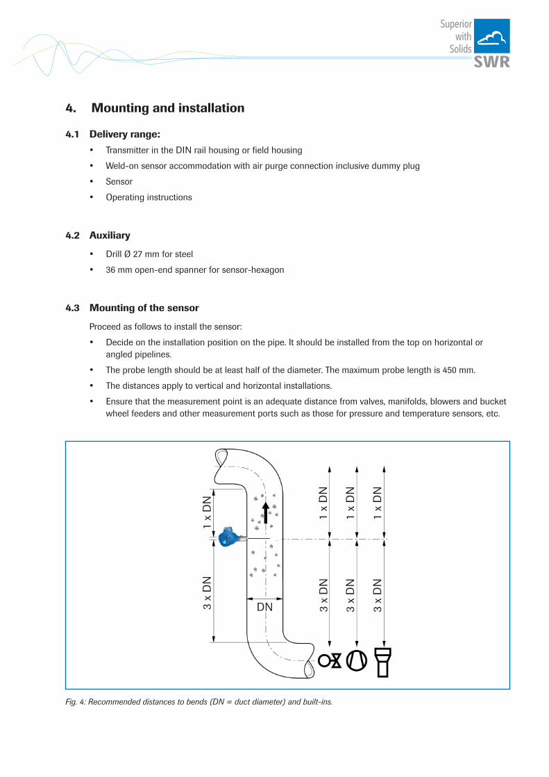
4.3 Mounting of the sensor
Proceed as follows to install the sensor:
• Decide on the installation position on the pipe. It should be installed from the top on horizontal or angled pipelines.
• The probe length should be at least half of the diameter. The maximum probe length is 450 mm.
• The distances apply to vertical and horizontal installations.
• Ensure that the measurement point is an adequate distance from valves, manifolds, blowers and bucket wheel feeders and other measurement ports such as those for pressure and temperature sensors, etc.
Fig. 4: Recommended distances to bends (DN = duct diameter) and built-ins.
3 x
DN
1 x
DN
3 x
DN
1 x
DN
1 x
DN
1 x
DN
3 x
DN
3 x
DN
DN

Superiorwith
Solids
• Weld the sensor accommodation to the duct.
• Drill the hole of 27 mm diameter through sensor accommodation.
Attention!
• After drilling it is essential to check whether the drill bit has caused any burr on the borehole edges. Any burr on the pipe must be removed using a suitable tool. If the burr is not removed it may affect the sensor‘s calibration.
• If the sensor is not installed immediately, insert a sealing plug until it is installed. Use a 36 mm open-ended spanner to tighten the sealing plug.
• Remove the sealing plug to insert the sensor.
• The sensor is delivered with a probe length adapted to the pipe diameter.
• The sensor is then inserted through the sensor receptacle and fixed.
• If purge air must be used, the connection is via a M5 connection nipple. Use purge air with a pressure of 1.2 . . . 1.5 bar (abs.).
Superiorwith
Solids
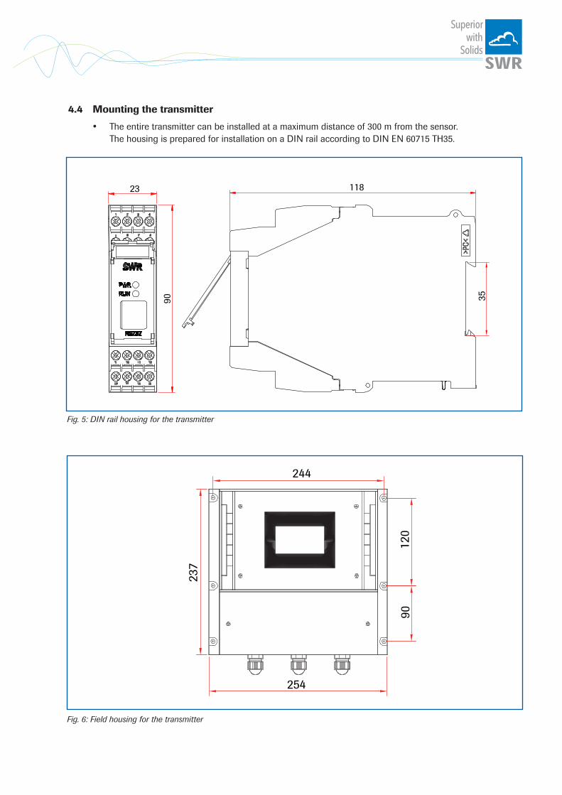
Fig. 5: DIN rail housing for the transmitter
Fig. 6: Field housing for the transmitter
4.4 Mounting the transmitter
• The entire transmitter can be installed at a maximum distance of 300 m from the sensor. The housing is prepared for installation on a DIN rail according to DIN EN 60715 TH35.
23
90
118
35
90120
244
254
237
Superiorwith
Solids
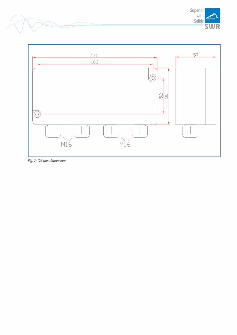
Fig. 7: C3-box dimensions

Superiorwith
Solids
4.5 Use in hazardous areas
Dust explosion zone identification: II 1/2D Ex tD IP 65 T84 °C Zone 20: 0 °C _< Tprocess _< 80 °C Zone 21: -10 °C _< Tamb _< 60 °C
- Equipment group 2- Equipment category: 1/2 Waveguide window zone 20 / housing zone 21- For explosive mixtures of air and combustible dust- IP code 65- Maximum surface temperature 84 °C at Ta = 60 °C
Gas explosion zone identification: II 1/2D Ex tD A20/21 IP 65 T84 °C II 2G Ex d IIC T5/T3
- Equipment group 2- Equipment category: 2- Zone 1- For explosive mixtures of air and combustible gases- IP code 65- Permitted process temperature 0 to 150 °C- Temperature class T3- Maximum surface temperature 84 °C at Ta = 60 °C
Tmax =150 °C
Tmax =60 °C
Ex hazard arrayDustEx zone 20GasEx zone 1
No Ex hazard arrayZone 21/22Zone 1/2

Superiorwith
Solids
5. Electrical connection
5.1 DIN rail terminal layout
Current output - 4 ... 20 mA
Current output + 4 ... 20 mA
Input Power supply 0 V DC
Input Power supply + 24 V DC
Not used Alarm relay NC (break contact)
Alarm relay C
Alarm relay NO (make contact)
1 2 3 4
5 6 7 8
Not used Not used RS 485 Interface Data B
RS 485 Interface Data A
Sensor connection Cable 4 RS 485 Data B
Sensor connection Cable 3 RS 485 Data A
Sensor connection Cable 2 Power supply 0 V
Sensor connection Cable 1 Power supply + 24 V
Fig. 9: Electrical connection of the transmitter
9 10 11 12
13 14 15 16
1 2 3 4
5 6 7 8
9 10 11 12
13 14 15 16

Superiorwith
Solids
TransmitterTerminal No. ConnectionPower supply connectionL / +24 V Input power supply 230 V / 50 Hz, 110 V / 60 Hz (optional 24 V DC)N / 0 V Input power supply 230 V / 50 Hz, 110 V / 60 Hz (optional 24 V DC)Earth EarthConnections
I-out1+ Current output + - Current output -
Na Not usedNa Not usedNa Not usedNa Not used
Min. / Max. relay
NO Floating change-over contact NO (make contact)C Floating change-over contact C (common conductor)
NC Floating change-over contact NC (break contact)
D-out+ Digital pulse output +- Digital pulse output -
RS 485A RS 485 interface data AB RS 485 interface data B
GND RS 485 interface ground
D-in1+ Digital interface 1 (+)- Digital interface 1 (-)
D-in2+ Digital interface 2 (+)- Digital interface 2 (-)
Sensor
+ Power supply + 24 V Cable no. 1GND Power supply 0 V Cable no. 2
A RS 485 data A Cable no. 3B RS 485 data B Cable no. 4
Shield Shield Shield
5.2 Field housing terminal layout
Fig. 10: Electrical connection
L NEr
de + - NO C NC
I-OUT1 NA NA Relay D-Out RS 485 D-In1 D-In2 SensorA B A B+ - + - + - + - + - + L N
Eart
h
GN
D
GN
D
Shie
ld

Superiorwith
Solids
Transmitter Sensor 1 Sensor 2 Sensor 3
Fig. 11: Electrical connection
5.3 C3-box terminal layout
Superiorwith
Solids
6. Operator interface
The operator interface differs depending on the system design:
• DIN rail housing without display, operation via PC software • Field housing with display, alternative operation via PC software • One to three sensor system
First of all, the different system versions are described below. Following that, the basic operation of the PicoFlow system as a one sensor system is then described without going back over the different versions.
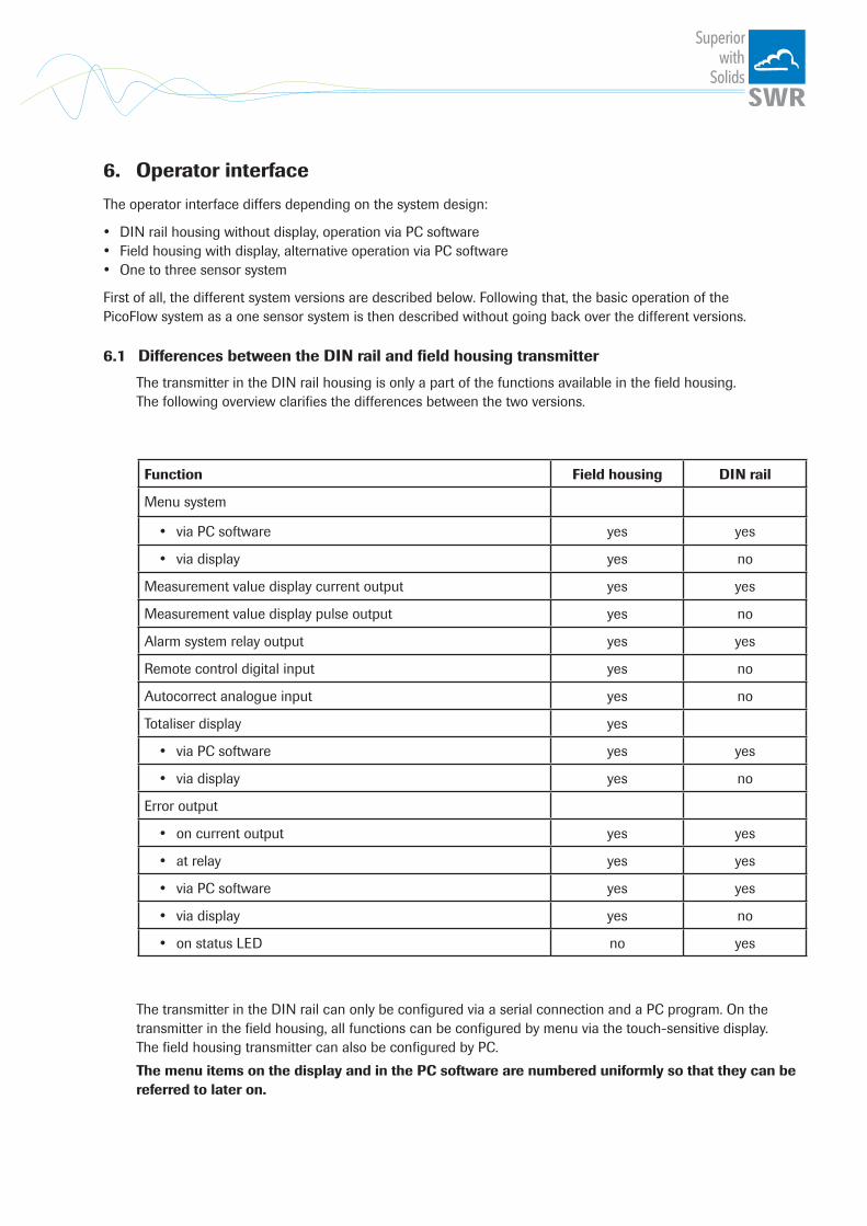
6.1 Differences between the DIN rail and field housing transmitter
The transmitter in the DIN rail housing is only a part of the functions available in the field housing. The following overview clarifies the differences between the two versions.
Function Field housing DIN rail
Menu system
• via PC software yes yes
• via display yes no
Measurement value display current output yes yes
Measurement value display pulse output yes no
Alarm system relay output yes yes
Remote control digital input yes no
Autocorrect analogue input yes no
Totaliser display yes
• via PC software yes yes
• via display yes no
Error output
• on current output yes yes
• at relay yes yes
• via PC software yes yes
• via display yes no
• on status LED no yes
The transmitter in the DIN rail can only be configured via a serial connection and a PC program. On the transmitter in the field housing, all functions can be configured by menu via the touch-sensitive display. The field housing transmitter can also be configured by PC.
The menu items on the display and in the PC software are numbered uniformly so that they can be referred to later on.

Superiorwith
Solids
6.2 DisplayIf just the display is used, all the main functions can be controlled via the display. The display is touch-sensitive and available keys are displayed directly in context.
The start page display the following values: • Tag No “PicoFlow“, freely selectable text which describes
the material or the measuring point • Measurement, here in [kg/s] • Totaliser value since the last totaliser reset,
here in [kg] • [ I ] key for info • [ R ] key for totaliser reset
To access the menus, press and hold any area of the display for several seconds. The sub-menu selection will be displayed:
In the menus and input fields, the displayed keys can be used to browse, select, edit or reject:
• Arrow: Scroll down the page, Select an option, Select a position in the input text
• [ E ] for ESC: Interrupt the function without making any changes
• Return: Select the function or confirm the input • [ C ] for Clear: Delete a symbol or number.
With button [ I ] an information window can be opened, in which raw value, temperature and sensor status can be checked.
If any data has been changed, the change will only be taken into account when you exit the complete menu structure and answer [ Yes ] when asked if you wish to save the changes.
For reasons of simplicity, a further display menu screen has been dispensed with. The display screens are directly derived from the menu structure in chapter 6.5.
Protection against unauthorised use:
If, a password has been entered in menu 7. System in 7.6. Password , which is different to the “0000” default setting, you will be asked to enter a password when attempting to access the menus. After the password has been successfully entered, the menus will be unlocked for approx. 5 minutes (from the last menu entry).
PF_5.03
41.23 kg /s
3728.25 kg
I
R
E
Main menu 5.03
1. Measurement range2. Calibration3. Alarm4. Analogue output �
#$
8
Save changes?
Y N
Sensor status Temp Raw value StatS1 ---- 123.0123 OKS2 ---- 213.0213 OKS3 ---- 321.0321 OKAverage value 219.0219
3728.25 kg
Superiorwith
Solids
6.3 PC interfaceWith the DIN rail version, communication with a laptop or PC is performed either on the terminals via an RS 485 or at the front via an RS 232 interface. The field housing version is connected to the terminals via an RS 485 interface or at the front via USB.
✔ The RS 485 connection is attached to the transmitter in the field housing at the ModBus A (+)and ModBus B (-) terminals on the DIN rail version, these connections are nos. 12 and 11, accordingly. RS 485 is a bus connection; the ModBus address and the baud rate can be set on the device. Upon delivery, the communication parameters are set to:
• ModBus address 1 • Baud rate 9600, 8, E,1
An RS 485 to USB adapter can be purchased from SWR.
✔ For the RS 232 connection to the DIN rail version, a special cable and USB converterare supplied. USB uses a standard USB-A-B cable. RS 232 and USB are point-to-point connections which are not bus-compatible. The ModBus address and baud rate for the front connections cannot be changed and are always:
• ModBus address 1 (or the device answers to all addresses) • Baud rate 9600, 8, E,1
When connected to the PC for the first time, any interface drivers enclosed with the transmitter must be installed.
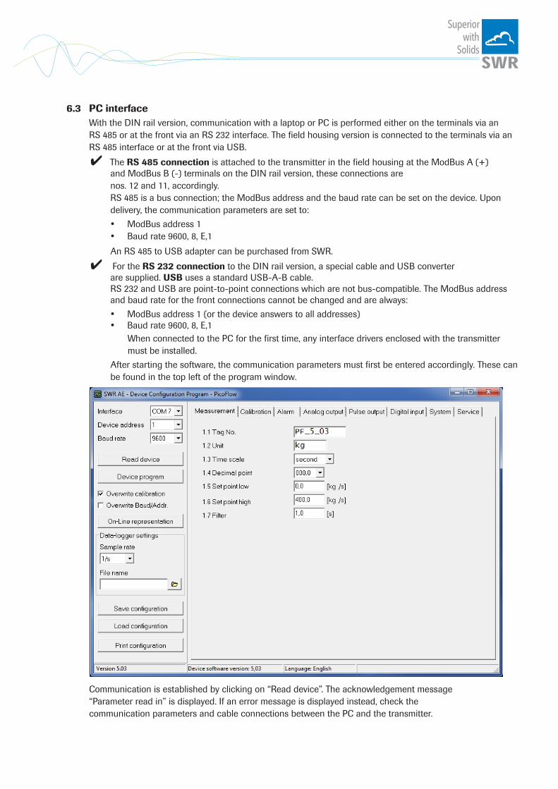
After starting the software, the communication parameters must first be entered accordingly. These can be found in the top left of the program window.
Communication is established by clicking on “Read device”. The acknowledgement message“Parameter read in” is displayed. If an error message is displayed instead, check thecommunication parameters and cable connections between the PC and the transmitter.
Superiorwith
Solids
The edited data is transmitted to the transmitter via “Device program”. Critical data concerning the ModBus communication and the calibration must be confirmed before the parameters are transmitted to the transmitter:
✔ If, when saving the the parameters in the transmitter, the system calibration datais changed, this action must be confirmed by checking “Overwrite calibration”.
✔ If, when saving the the parameters in the transmitter, the system interface parameters are changed, this must be confirmed by checking the selection “Overwrite Baud/Addr.”.
In addition, with the PC software,
• the transmitter parameters can be saved in a file (Save configuration) • the transmitter parameters can be loaded from a file (Load configuration) • the transmitter parameters can be printed (Print configuration) • the measured values can be logged in a data logger file (enter the file name and storage rate, and
activate the data logger on the online display)
The software language can be set by right-clicking the “Sprache/Language/Langue” field in the bottom program line on “German/English/French”.
Protection against unauthorised use:The PC interface does not have a password prompt as it is assumed that only authorised personnel will have access to the PC and the software. However, the password to operate the display can be read and changed in menu 7. System in 7.6. Password.
Superiorwith
Solids
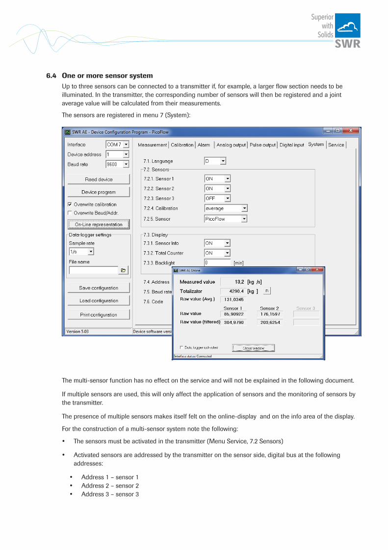
6.4 One or more sensor systemUp to three sensors can be connected to a transmitter if, for example, a larger flow section needs to be illuminated. In the transmitter, the corresponding number of sensors will then be registered and a joint average value will be calculated from their measurements.
The sensors are registered in menu 7 (System):
The multi-sensor function has no effect on the service and will not be explained in the following document.
If multiple sensors are used, this will only affect the application of sensors and the monitoring of sensors by the transmitter.
The presence of multiple sensors makes itself felt on the online-display and on the info area of the display.
For the construction of a multi-sensor system note the following:
• The sensors must be activated in the transmitter (Menu Service, 7.2 Sensors)
• Activated sensors are addressed by the transmitter on the sensor side, digital bus at the following addresses:
• Address 1 – sensor 1 • Address 2 – sensor 2 • Address 3 – sensor 3

Superiorwith
Solids
• With delivery of a multi-sensor system the sensors will be preconfigured on the addresses 1 – 2 – 3 and noted in the transmitter as active.
• Sensors and transmitters, which are not preconfigured for a multi-sensor system always have address 1, only sensor 1 will be activated.
• Sensors which are inserted afterwards in a system must be adjusted by means of an separate service software to the required address.
• The correct address will be factory-preset when ordering spare parts with specified sensor number.
Procedure with a multi-sensor system with no pre-configured sensors:
Always note:
• Disconnection of power before electrical mounting!
• Specify the necessary number of sensors of a measuring point (see example with 3 Sensors)
• Connection of power supply and C3-Box to the transmitter
• Activation of 3 sensors see menu 7.2 (configuration software or display)
• Connection of sensor 3 to the transmitter: the sensor logs in as sensor 1
• For setting the sensor on address 3 use the service software, the sensor will log in as sensor 3
• For setting sensor 2 on address 2, it is the same procedure
• Connect at last Sensor 1

Superiorwith
Solids
6.5 Menu structureThe menu structure supports the user when adjusting the measuring range, the calibration, the measurement values and the choice of additional functions. In this connection, the numbering both on the display and in the PC interface is identical:
1. Measurement range
1.1 Tag No. Input: Free text (10 characters) Name of the measurement point or product.
1.2 Unit Input: Unit text, e. g. kg Required mass flow unit.
1.3 Time scale Selection: hour / minute /second time base for the integration by the totaliser and the pulse output.
1.4 Decimal point Selection: 0000, 0.000, 00.00, 000.0 Number representation and decimal point- accuracy in the measurement menu.
1.5 Set point low Input: 0 … 9999 Throughput rates under this value will not be displayed at the current output. This does not concern the display indicator, totaliser or pulse output.
1.6 Set point high Input: 0 … 9999 Throughput rates above this value will not be displayed at the current output. This does not concern the display indicator, totaliser or pulse output.
1.7 Filter Input: 0.0 s … 999.9 s Filtering of measurement for the indicator and the output values.
Superiorwith
Solids
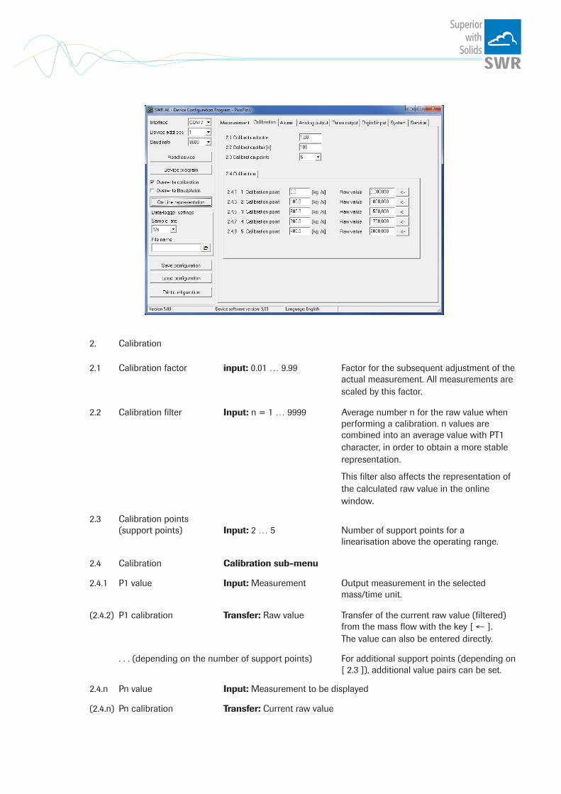
2. Calibration 2.1 Calibration factor input: 0.01 … 9.99 Factor for the subsequent adjustment of the actual measurement. All measurements are scaled by this factor.
2.2 Calibration filter Input: n = 1 … 9999 Average number n for the raw value when performing a calibration. n values are combined into an average value with PT1 character, in order to obtain a more stable representation.
This filter also affects the representation of the calculated raw value in the online window.
2.3 Calibration points (support points) Input: 2 … 5 Number of support points for a linearisation above the operating range.
2.4 Calibration Calibration sub-menu
2.4.1 P1 value Input: Measurement Output measurement in the selected mass/time unit.
(2.4.2) P1 calibration Transfer: Raw value Transfer of the current raw value (filtered) from the mass flow with the key [ ← ]. The value can also be entered directly.
. . . (depending on the number of support points) For additional support points (depending on [ 2.3 ]), additional value pairs can be set.
2.4.n Pn value Input: Measurement to be displayed
(2.4.n) Pn calibration Transfer: Current raw value
Superiorwith
Solids
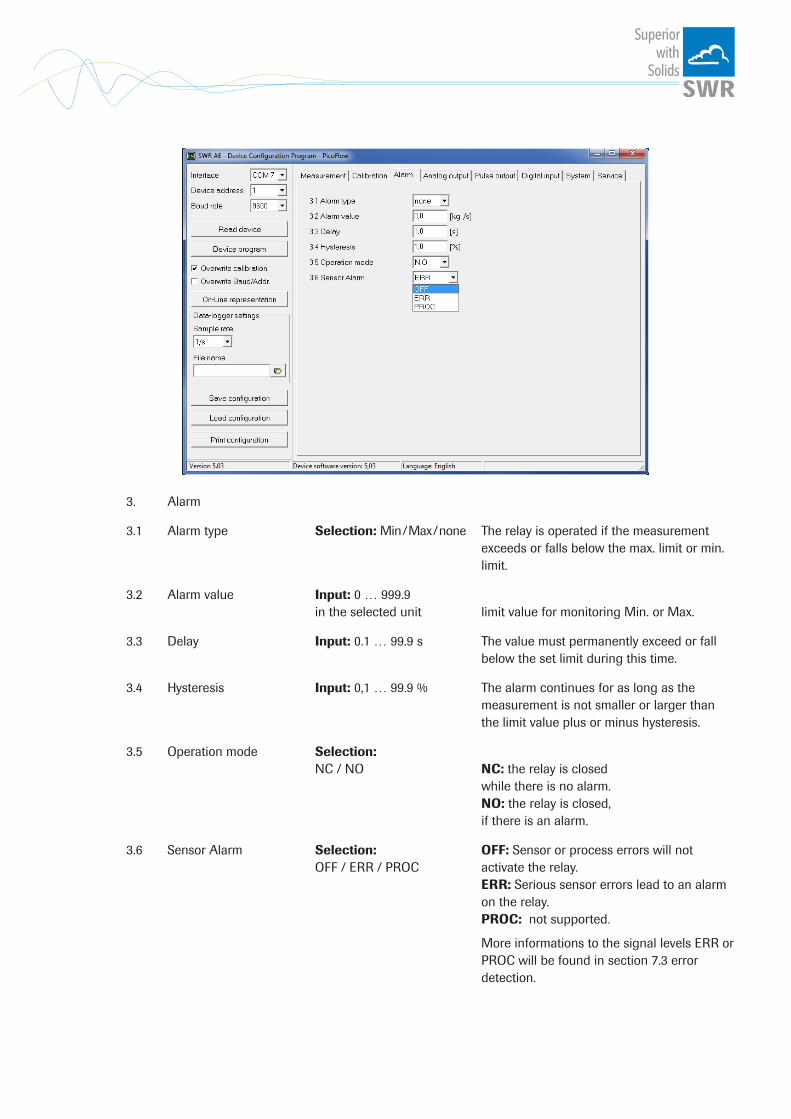
3. Alarm
3.1 Alarm type Selection: Min / Max / none The relay is operated if the measurement exceeds or falls below the max. limit or min. limit.
3.2 Alarm value Input: 0 … 999.9 in the selected unit limit value for monitoring Min. or Max.
3.3 Delay Input: 0.1 … 99.9 s The value must permanently exceed or fall below the set limit during this time.
3.4 Hysteresis Input: 0,1 … 99.9 % The alarm continues for as long as the measurement is not smaller or larger than the limit value plus or minus hysteresis.
3.5 Operation mode Selection: NC / NO NC: the relay is closed while there is no alarm. NO: the relay is closed, if there is an alarm.
3.6 Sensor Alarm Selection: OFF: Sensor or process errors will not OFF / ERR / PROC activate the relay. ERR: Serious sensor errors lead to an alarm on the relay. PROC: not supported.
More informations to the signal levels ERR or PROC will be found in section 7.3 error detection.
Superiorwith
Solids
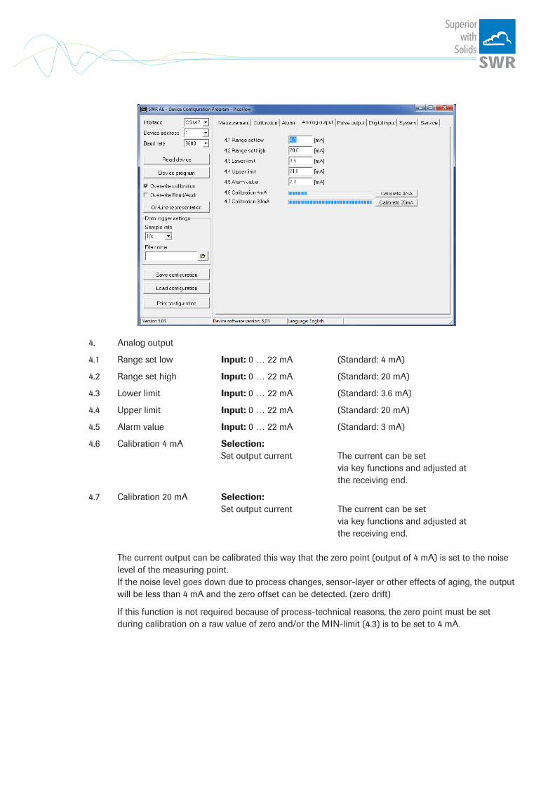
4. Analog output
4.1 Range set low Input: 0 … 22 mA (Standard: 4 mA)
4.2 Range set high Input: 0 … 22 mA (Standard: 20 mA)
4.3 Lower limit Input: 0 … 22 mA (Standard: 3.6 mA)
4.4 Upper limit Input: 0 … 22 mA (Standard: 20 mA)
4.5 Alarm value Input: 0 … 22 mA (Standard: 3 mA)
4.6 Calibration 4 mA Selection: Set output current The current can be set via key functions and adjusted at the receiving end.
4.7 Calibration 20 mA Selection: Set output current The current can be set via key functions and adjusted at the receiving end.
The current output can be calibrated this way that the zero point (output of 4 mA) is set to the noise level of the measuring point. If the noise level goes down due to process changes, sensor-layer or other effects of aging, the output will be less than 4 mA and the zero offset can be detected. (zero drift)
If this function is not required because of process-technical reasons, the zero point must be set during calibration on a raw value of zero and/or the MIN-limit (4.3) is to be set to 4 mA.

Superiorwith
Solids
5. Pulse output
5.1 Pulses per unit Input: 0.01… 99.9 The set number of pulses is emitted for each mass unit.
e. g.: Tonnes are selected as the mass unit, 10 is selected as the number of pulses per mass unit: 1000 kg/10 = 100 kg. A pulse will be emitted every 100 kg.
To improve readability, for connected systems (SPC, PLC, counters, etc.) the maximum pulse frequency is 50 Hz. If the number of pulses to be emitted per second exceeds this frequency, they will be emitted with a delay.

Superiorwith
Solids
6. Digital input
6.1 Digital input 1
6.1.1 Function Selection: none / reset totaliser / AutoCal One of the functions can be executed remotely via the digital input.
6.1.2 Normally open / closed (working direction) Selection: NO / NC If necessary, invert the value of the input level.
6.1.3 Filter Input: 0.1… 99.9 s Time during which the requested signal must remain pending.
6.2 Digital input 2 As digital input 1
Superiorwith
Solids
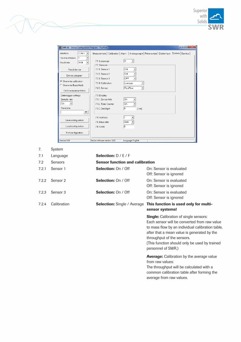
7. System
7.1 Language Selection: D / E / F
7.2 Sensors Sensor function and calibration
7.2.1 Sensor 1 Selection: On / Off On: Sensor is evaluated Off: Sensor is ignored
7.2.2 Sensor 2 Selection: On / Off On: Sensor is evaluated Off: Sensor is ignored
7.2.3 Sensor 3 Selection: On / Off On: Sensor is evaluated Off: Sensor is ignored
7.2.4 Calibration Selection: Single / Average This function is used only for multi- sensor systems!
Single: Calibration of single sensors: Each sensor will be converted from raw value to mass flow by an individual calibration table, after that a mean value is generated by the throughput of the sensors. (This function should only be used by trained personnel of SWR.) Average: Calibration by the average value from raw values: The throughput will be calculated with a common calibration table after forming the average from raw values.
Superiorwith
Solids
7.2.5 Sensor Selection: The transmitter verifies the availability of SolidFlow / PicoFlow registered sensors on the selected type, calculates the measurement values on this basis and signals if necessary corresponding errors.
Incorrect sensor selection leads to a refusal to communicate.
7.3. Display
7.3.1 Sensor info Selection: On / Off Show/hide Info key
7.3.2 Total Counter Selection: On / Off Display/do not display totaliser value
7.3.3 Backlight Input: 0 … 99 Display lighting in minutes 0 = continuously 1… 99 min 7.4 Baud rate selection: 4800/9600/19200/ 38400 baud Communication speed of the transmitter if operated on a PLC or PC as a ModBus-slave.
7.5 Address Input: 1… 255 ModBus address of transmitter, if operated on a PLC or PC as a slave.
7.6 Code
Superiorwith
Solids
7. Start-up procedure7.1 Basic start-up
Upon delivery, the sensor is not calibrated to the product to be measured and must be parameterised when started up. During the process, the mass flows measured by the sensor will be assigned to the display values and output quantities required by the user.
The following points must first be checked:
• Check sensor is flush with the internal surface of the pipeline. • The correct connection between the sensor and the transmitter. • A warm-up time of approx. 5 minutes before starting calibration and after switching on the sensor's
power supply.
The expected flow rate must first be determined for the measurement point, and the required measuring range and physical units must be entered in menu 1 (Measurement). The system is then calibrated on at least two operating points (one empty measurement and one operating point) in menu 2 (Calibration):
Min point While there is no mass flow, the 1st point is set to 0 and the calibration for the zero point is performed.
Max point During normal conveyance, the 2nd point is set to a known flow rate and calibration is also performed. The value can be corrected afterwards during weighing.
The device has thus performed its basic function and the measurements are displayed.
Additional support points If non-linearities occur when measuring with different flow rates, up to 5 support points can be selected in menu 2 (Calibration). These support points can then be calibrated with different flow rates.
7.2 Adjusting the measurement valuesThe system's additional functions can be set in the following menus:
Alarms Values for flow rate lower or upper limits can be set in menu 3 (Alarm). A sensor monitoring alarm can also be activated here.
Analogue output The assignment of the analogue output values will be in menu 4 (Analogue output). Here the corresponding output value will be assigned to the required measuring range (4 ... 20 mA). Upper and lower limits of the permitted power and power in the event of failure are set here. Power output can also be calibrated here.
Pulse output An internal totaliser function integrates the mass flow over time. In menu 5 (Pulse output), the pulse output can be configured, so that the system emits pulses corresponding to a defined conveyed mass.
Digital input In menu 6 (Digital input) various functions and their working direction can be assigned to the system’s digital inputs.
System In menu 7 (System), functions such as selection of the menu language, the number of connected sensors and their average, the display screen or ModBus addressing and speed are summarised. Totaliser The entire flow volume since the last totaliser reset can be read with the totaliser function. A reset can be performed via an external control cable (see menu 6 (Digital input)) or directly via the Display by pressing the R symbol (see menu 7 (System)).
Superiorwith
Solids
7.3 Error signalling
For monitoring the availability a wide range of functions for self-diagnostics were integrated, in order to signal various errors:
Fatal errors (ERR) lead to a failure of the entire system and always set the current output of the system to alarm value and can optionally activate the relay:
• Failure of the communication to a sensor (sensor failure) • Failure of a subcomponent of a sensor (temperature monitoring, heating control, memory, data
consistency etc. on the sensor) • Inconsistency of signal paths in the sensor (the amplifier stages, DC offsets, sampling rate)
Type of fault Display (Field housing)
Run-LED (DIN rail)
Relay (optional)
Current output
No fault Sensor status OK on the information display (Button [I])
Single flash every second
Normal state 4 ... 20 mA
ERR Display with error code in the bottom display line; advan-ced information on key [I]
Triple flash every second
Activated, when Relais-Alarm-Option ERR is chosen
2 mA (or for the current output adjusted, chosen alarm value)
Error codes are composed of the letter S, supplemented by a 3-digit hexadecimal value from „000” to „FFF”. In this code, single errors will be signalled in the different bit positions.
Time Out error: In order not to complicate the start up of a process plant by process- or heating status errors, nonfatal errors will be signalled only after a period of about 5 minutes after a reset of the measuring system at the outputs. The time-out period is visible in a small “t” in the left upper corner of the display(field housing only).
7.4 Compatibility
For the PicoFlow systems two different software versions for the transmitter and associated PC software are available.
The two versions are not compatible to one another.
Sensor Transmitter (Field housing or DIN rail)
PC software
All PicoFlow
(Pre-version based on PS) (Pre-version based on PS)
V.5.03 V.5.03

Superiorwith
Solids
8. Connection examples
8.1 Digital input
▼
UST
8.2 Impulse output
R = (Ub - 0,7 V)/l
RV = ((UST - 1,6 V) / 20 mA) - 2 kW
Open: 0 VClosed: Ub - 0.7 V
Open: UbClosed: 0.7 V
Open Collector
Open Collector
Superiorwith
Solids
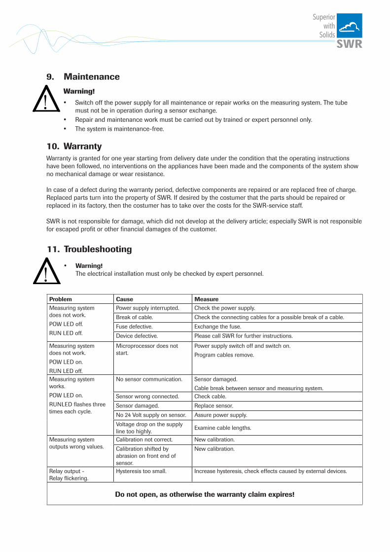
9. Maintenance
Warning!
• Switch off the power supply for all maintenance or repair works on the measuring system. The tube must not be in operation during a sensor exchange.
• Repair and maintenance work must be carried out by trained or expert personnel only. • The system is maintenance-free.
10. WarrantyWarranty is granted for one year starting from delivery date under the condition that the operating instructions have been followed, no interventions on the appliances have been made and the components of the system show no mechanical damage or wear resistance. In case of a defect during the warranty period, defective components are repaired or are replaced free of charge. Replaced parts turn into the property of SWR. If desired by the costumer that the parts should be repaired or replaced in its factory, then the costumer has to take over the costs for the SWR-service staff. SWR is not responsible for damage, which did not develop at the delivery article; especially SWR is not responsible for escaped profit or other financial damages of the customer.
11. Troubleshooting
• Warning! The electrical installation must only be checked by expert personnel.
Problem Cause MeasureMeasuring system does not work.
POW LED off.
RUN LED off.
Power supply interrupted. Check the power supply.
Break of cable. Check the connecting cables for a possible break of a cable.
Fuse defective. Exchange the fuse.
Device defective. Please call SWR for further instructions.
Measuring system does not work.
POW LED on.
RUN LED off.
Microprocessor does not start.
Power supply switch off and switch on.
Program cables remove.
Measuring system works.
POW LED on.
RUNLED flashes three times each cycle.
No sensor communication. Sensor damaged.
Cable break between sensor and measuring system.Sensor wrong connected. Check cable.
Sensor damaged. Replace sensor.
No 24 Volt supply on sensor. Assure power supply.
Voltage drop on the supply line too highly.
Examine cable lengths.
Measuring system outputs wrong values.
Calibration not correct. New calibration.
Calibration shifted by abrasion on front end of sensor.
New calibration.
Relay output - Relay flickering.
Hysteresis too small. Increase hysteresis, check effects caused by external devices.
Do not open, as otherwise the warranty claim expires!

Superiorwith
Solids
12. Technical data
Sensor / Sensor accommodation
Housing Aluminium
Protection category IP 66
Operating temperature -20 ... + 60 °C (max. 150 °C)
Max. working pressure 2 bar, optional 10 bar
Weight 1.5 kg
Sensor rod Material: ceramic protected stainless steel; max. 450 mm
Accuracy ± 5 % in calibrated range
Transmitter field housing
Power supply 110 / 230 V AC 50 Hz (optional 24 V DC)
Power consumption 20 W / 24 VA
Protection category IP 65 to EN 60 529/10.91
Operating temperature -10 ... +45 °C
Dimensions 258 x 237 x 174 (W x H x D)
Weight Approx. 2.5 kg
Interface RS 485 / RS 232 C (ModBus)
Cable glands 3 x M16 (4.5 - 10 mm Ø)
Screw terminals 0.2 – 2.5 mm² [AWG 24-14]
Current output signal 4 ... 20 mA (0 ... 20 mA), load < 500 W
Measurement value alarm relay output Relay with switching contact - Max. 250 V AC, 1 A
Data storage Flash
Pulse output Open Collector - Max. 30 V, 20 mA
Transmitter DIN Rail
Power supply 24 V DC ± 10 %
Power consumption 20 W / 24 VA
Protection category IP 40 to EN 60 529
Operating temperature -10 ... +45 °C
Dimensions 23 x 90 x 118 (W x H x D)
Weight Approx. 172 g
DIN Rail mounting DIN 60715 TH35
Terminal clamp wire size 0.2 – 2.5 mm² [AWG 24-14]
Current output signal 4 ... 20 mA (0 ... 20 mA), load < 500 W
Measurement value alarm relay output Relay with switching contact - Max. 250 V AC, 1 A
Data storage Flash
All
right
s re
serv
ed.
EN 25/04/2017
SWR engineering Messtechnik GmbHGutedelstraße 31 · 79418 Schliengen (Germany) Fon +49 7635 827248-0 · Fax +49 7635 827248-48 · www.swr-engineering.com
Superiorwith
Solids