physics subject area test waves light & optics
TRANSCRIPT

Physics Subject Area Test
WAVESLIGHT & OPTICS


Vibrations and Waves

Simple Harmonic Motion
A restoring force is one that moves a system back to an equilibrium position.
Example: mass on frictionless table, attached to spring.
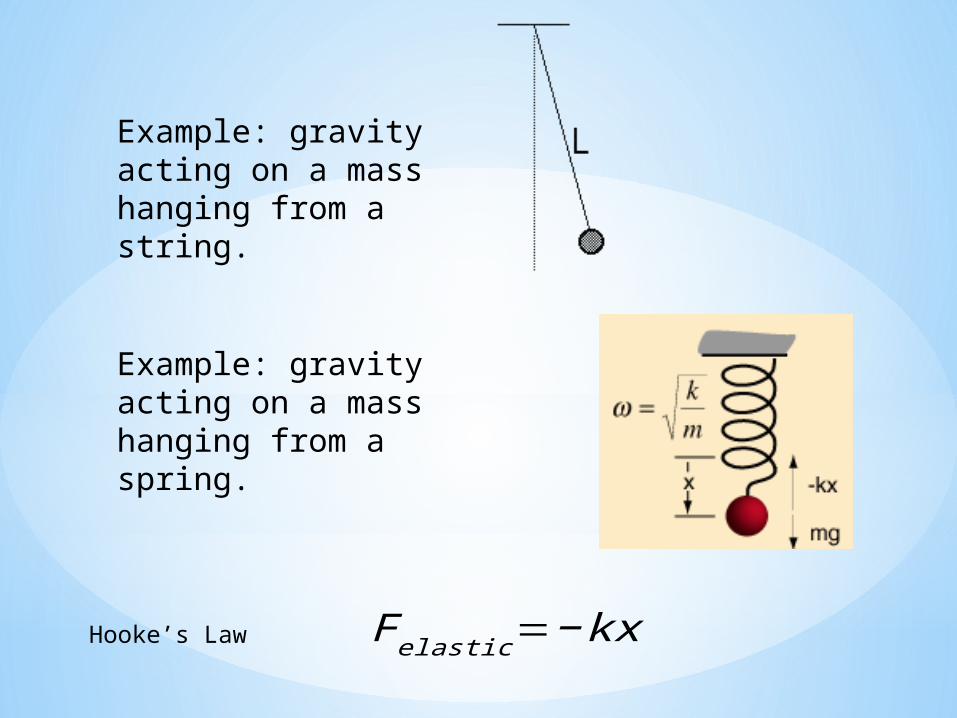
Example: gravity acting on a mass hanging from a string.
Example: gravity acting on a mass hanging from a spring.
Hooke’s Law F elastic=−kx

When the restoring force is linearly proportional to the amount of the displacement from equilibrium, the force is said to be a Hooke’s Law force.

When oscillations are small, the motion is called simple harmonic motion (shm) and can be described by a simple sine curve.

Wave PropertiesWavelength
Wavelength, l, is the distance between two consecutive peaks.

Wave PropertiesAmplitude
Amplitude is the height of the wave above or below the equilibrium point.

Wave PropertiesPeriod
The wave period, P, this the time it take one wave to pass
the observer.

Wave PropertiesFrequency
Frequency, f, is the number of waves passing a particular point in one second.

T 1T
f
T
f
T
fT
f Tf fTf
In symbolic form
or
f

Wave Motion, Speed, Type
Waves transfer energy, not matter, from one place to another
A Vibrating source transfers a disturbanceSpeed depends on type of vibrating source and
medium through which it travelsWave speed = f x The same type of wave moves at the same speed regardless of f or
For any wave, f is inversely proportional to

VIBRATION OF A PENDULUM
What does the period (T) depend upon?
Length of the pendulum (l )Acceleration due to gravity (g ).
Period does not depend upon the bob mass or the amplitude of the swing.
Vibration of a pendulum. The to-and-fro vibratory motion is also called oscillatory motion (or oscillation).
T=2𝜋 √ lg

Wave Type
Transverse waves vibrate across from direction of travel
Longitudinal waves vibrate along the direction of travel (as in a spring)

Sound Waves
Molecules in the air vibrate about some average position creating the compressions and rarefactions. We call the frequency of sound the pitch.

*Wave Interference
When two wave pass each other their superposition
causes reinforcement or cancellation.

The Speed of Sound : Standing Waves
*Speed of sound (in air, 0⁰C, 1 atm) = 331 m/s

The standing sound wave in the column of air in a tube closed at one end must have a displacement node at the closed end and antinode at the open end
Only odd multiples are possible λ1 = 4L, λ2 = 4/3L, λ3 = 4/5L, λ4 = 7/4L, …
Eigenfrequencies: (f = v/ λ)
f1 = v/4L, f2 = 3v/4L, f3 = 5v/4L, …
A tube closed at one end:

A tube open at both ends:
eigenfrequencies

*The Doppler Shifthttp://www.astro.sunysb.edu/mzingale/software/astro/doppler.avi
A receiver will detect a higher frequency when the source is approaching, and a lower frequency when the source is moving away from the receiver.
f’/ f = v’/v f’ = f (1 ± VR/v)
Doppler shift, moving receiver
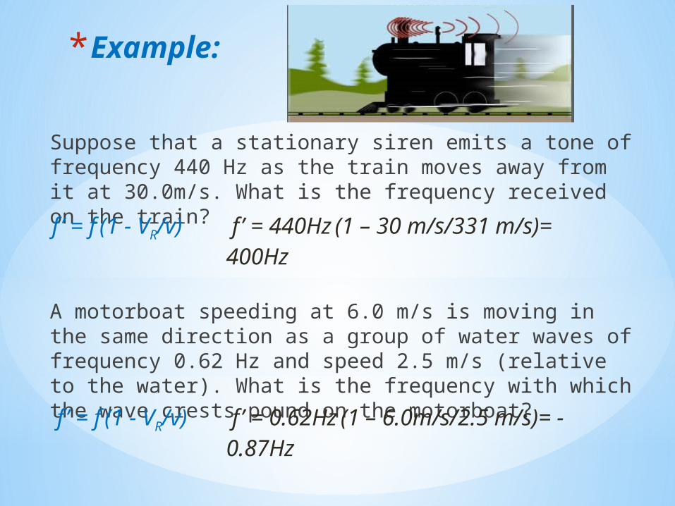
*Example:
Suppose that a stationary siren emits a tone of frequency 440 Hz as the train moves away from it at 30.0m/s. What is the frequency received on the train?
A motorboat speeding at 6.0 m/s is moving in the same direction as a group of water waves of frequency 0.62 Hz and speed 2.5 m/s (relative to the water). What is the frequency with which the wave crests pound on the motorboat?
f’ = f (1 - VR/v) f’ = 440Hz (1 – 30 m/s/331 m/s)= 400Hz
f’ = f (1 - VR/v) f’ = 0.62Hz (1 – 6.0m/s/2.5 m/s)= -0.87Hz

Reflection and Refraction
*Lenses work because light slows down in media other than a vacuum.
*The speed of light is given by:
*n is the index of refraction
n
cvlight

*Example indices of refraction
Substance n vacuum 1air 1.0003water 1.3glass 1.5
Index of refraction is unitless

Traveling between media
*When light encounters a boundary between two media, some of the light is reflected and some is transmitted into the new medium.*If the light strikes the boundary at an angle, the transmitted light is refracted.

Light rays vs. waves in diagramsWe usually use ray diagrams in geometric optics
*Ray diagram: rays point perpendicular to the wavefront.
• Wave diagram: shows the crests of the traveling waves

Three rules for calculating reflection and refraction.
1. All angles are measured from the normal. The normal is the line perpendicular to the surface at the point of reflection.

Three rules for calculating reflection and refraction.
2. The reflected angle is equal to the incident angle.
ir

ffii nn sinsin
Three rules for calculating reflection and refraction.
3. Snell’s Law for refraction

*A ray of light strikes the surface of a beaker of hydrogen peroxide (n = 1.414) making a 30º angle with the surface normal.
*What angle does the reflected ray make with the normal?
*What angle does the transmitted ray make with the normal?

*a) The angle of the reflected ray is the same as the incident ray, 30º
*b)
7.20
354.0sin
sin414.130sin1
sinsin
f
f
f
fperoxideiair nn

Critical angle
*The critical angle of incidence results in a transmitted ray that is parallel to the boundary surface.

Total internal reflection
*If the angle of incidence is greater than the critical angle, all the light is reflected and none is transmitted.
1
21sinn
ncritical

Optics Using Lenses
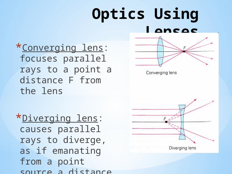
*Converging lens: focuses parallel rays to a point a distance F from the lens
*Diverging lens: causes parallel rays to diverge, as if emanating from a point source a distance F behind the lens

Lens Equation
*di =distance from lens to image
*d0 =distance from lens to object
*f = focal length of lens0
111
ddf i

*Lens Equation
*f is positive for converging lens*f is negative for diverging lens*Negative di is an image on the same side of the lens as the object*Positive di is an image on the opposite side of the lens as the object
0
111
ddf i

Real and Virtual Images
*If the light rays actually pass through the point they appear to come from, the image is real.
*If the light rays are not actually coming from this position, the image is virtual.

*Example of a virtual image

*Ray tracing

Ray Tracing for Converging Lenses
1. Draw the lens, the object (arrow), and both focuses (F).

2. Draw a ray from the top of the object to the lens. This ray will be parallel to the axis of the optical system until it strikes the lens. Then is bends to pass through the focus. (Red ray)

3. Draw a ray passing from top of the object through the center of the lens. (Blue ray)
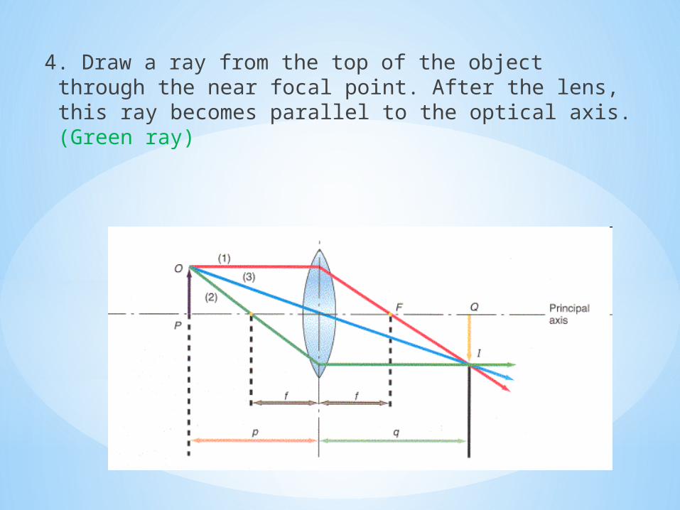
4. Draw a ray from the top of the object through the near focal point. After the lens, this ray becomes parallel to the optical axis. (Green ray)
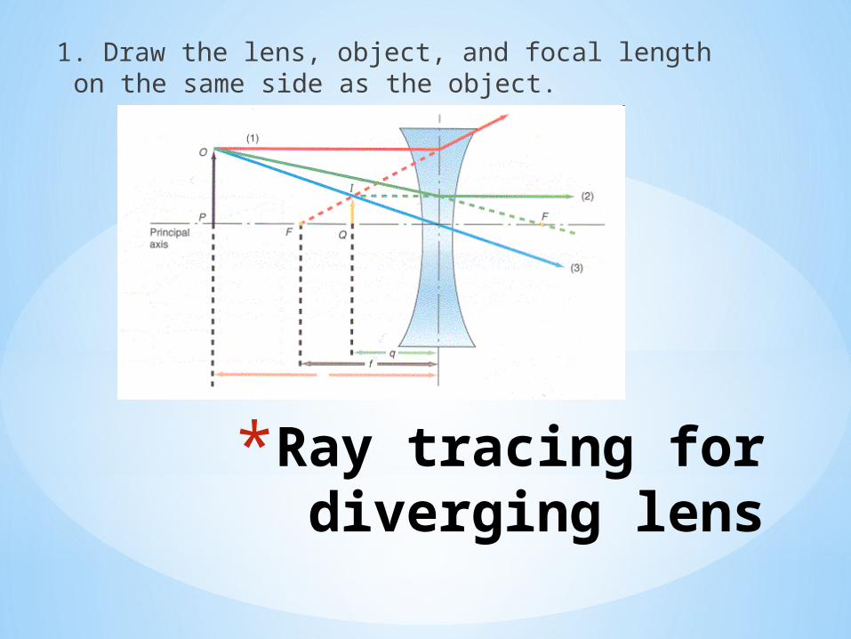
*Ray tracing for diverging lens
1. Draw the lens, object, and focal length on the same side as the object.

2. Draw a line from the top of the object to the lens, parallel to the optical axis. After the lens, draw the line as if it had come from the near focus. (Red ray)

3. Draw ray from the top of the object towards the far focus. After the lens, this ray become parallel to the optical axis. (Green ray)

4. Draw a ray from the top of the image through the center of the lens. (Blue ray)

Law of Reflection
*The angle of reflection is equal to the angle of incidence, measured with respect to the normal.
ri

*The thin lens equation we used before can also be applied to mirrors.
*In the case of mirrors, a positive di means the image is on the same side of the mirror as the object.
*This sign convention is opposite that used for lenses.
oi ddf
111

Plane mirror
*The focal point of a plane mirror is at infinity.
*The image formed by a plane mirror is virtual and upright.
*To trace rays reflecting off a plane mirror, just use law of reflection.

Images in a plane mirror
*The image distance and object distance are the same for a plane mirror.
oi
oi
dd
f
ddf
01
111

Spherical Mirrors
*A spherical mirror is a section of a sphere.
*If the outside surface of the sphere is reflecting, the mirror is convex.
*If the inside surface is reflecting, the mirror is concave.

*Ray tracing - concave

*1. Draw ray from top of object to the curved mirror. After reflecting off mirror, the ray passes through the focal point. (Blue ray)

*2. Draw a ray from the top of the object through the focal point. The ray will be parallel to the optical axis after reflecting. (Green)

Ray tracing image - convex
The rays do not intersect, so we must extend them, resulting in a virtual image.

1. Draw ray parallel to optical axis. After reflection, this ray travels as if it is coming from the far focus. (Blue ray)

2. Draw line from top of object to focus. At the mirror, the ray becomes parallel to the optical axis. (Green ray)