physical layer - wbuthelp.com · physical layer is concerned with transmitting raw bits over a...
TRANSCRIPT
Physical layer is concerned with transmitting raw bits over a communication channel. The design issues have to do with making sure that when one side sends a 1 bit, it is received by the other side as 1 bit and not as 0 bit. In physical layer we deal with the communication medium used for transmission.
Physical Layer
Types of Medium
Medium can be classified into 2 categories.
1. Guided Media: Guided media means that signals is guided by the prescience of physical media i.e. signals are under control and remains in the physical wire. For eg. Copper wire.
2. Unguided Media: Unguided Media means that there is no physical path for the signal to propagate. Unguided media are essentially electro-magnetic waves. There is no control on flow of signal. For eg. Radio waves.
Communication Links
In a network nodes are connected through links. The communication through links can be classified as
1. Simplex: Communication can take place only in one direction. eg. T.V broadcasting. 2. Half-duplex: Communication can take place in one direction at a time. Suppose node A
and B are connected then half-duplex communication means that at a time data can flow from A to B or from B to A but not simultaneously. eg. two persons talking to each other such that when speaks the other listens and vice versa.
3. Full-duplex: Communication can take place simultaneously in both directions. eg. A discussion in a group without discipline.
Links can be further classified as
1. Point to Point: In this communication only two nodes are connected to each other. When a node sends a packet then it can be received only by the node on the other side and none else.
2. Multipoint: It is a kind of sharing communication, in which signal can be recieved by all nodes. This is also called broadcast.
Generally two kinds of problems are associated in transmission of signals.
1. Attenuation: When a signal transmits in a network then the quality of signal degrades as the signal travels longer distances in the wire. This is called attenuation. To improve quality of signal amplifiers are used at regular distances.
mywbut.com
1
2. Noise: In a communication channel many signals transmits simultaneously, certain random signals are also present in the medium. Due to interference of these signals our signal gets disrupted a bit.
Bandwidth
Bandwidth simply means how many bits can be transmitted per second in the communication channel. In technical terms it indicates the width of frequency spectrum.
Transmission Media
Guided Transmission Media In Guided transmission media generally two kind of materials are used.
1. Copper o Coaxial Cable o Twisted Pair
2. Optical Fiber
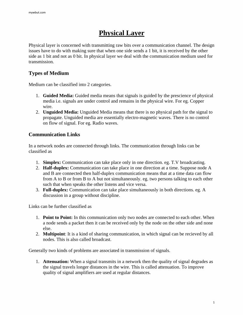
1. Coaxial Cable: Coaxial cable consists of an inner conductor and an outer conductor which are separated by an insulator. The inner conductor is usually copper. The outer conductor is covered by a plastic jacket. It is named coaxial because the two conductors are coaxial. Typical diameter of coaxial cable lies between 0.4 inch to 1 inch. The most application of coaxial cable is cable T.V. The coaxial cable has high bandwidth, attenuation is less.
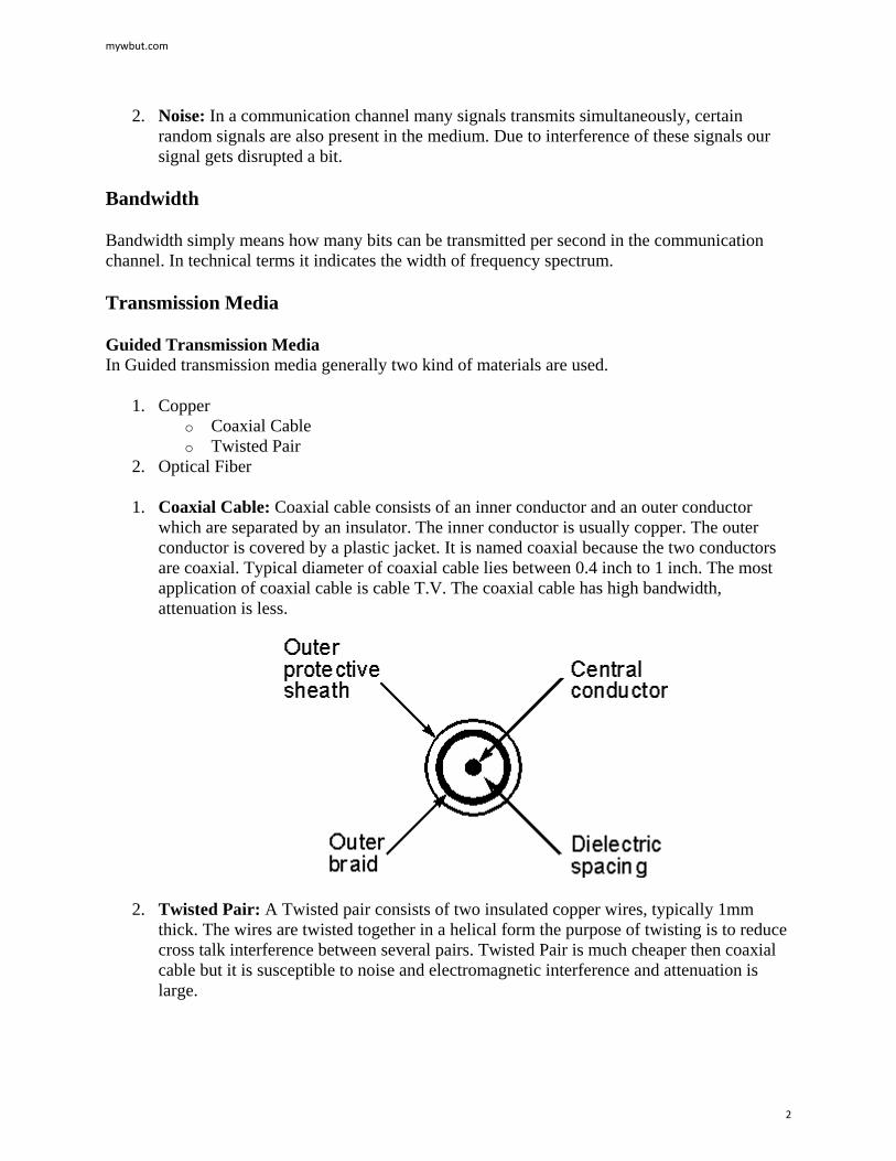
2. Twisted Pair: A Twisted pair consists of two insulated copper wires, typically 1mm thick. The wires are twisted together in a helical form the purpose of twisting is to reduce cross talk interference between several pairs. Twisted Pair is much cheaper then coaxial cable but it is susceptible to noise and electromagnetic interference and attenuation is large.
mywbut.com
2
Twisted Pair can be further classified in two categories: Unshielded twisted pair: In this no insulation is provided, hence they are susceptible to interference. Shielded twisted pair: In this a protective thick insulation is provided but shielded twisted pair is expensive and not commonly used.
The most common application of twisted pair is the telephone system. Nearly all telephones are connected to the telephone company office by a twisted pair. Twisted pair can run several kilometers without amplification, but for longer distances repeaters are needed. Twisted pairs can be used for both analog and digital transmission. The bandwidth depends on the thickness of wire and the distance travelled. Twisted pairs are generally limited in distance, bandwidth and data rate.
3. Optical Fiber: In optical fiber light is used to send data. In general terms presence of light is taken as bit 1 and its absence as bit 0. Optical fiber consists of inner core of either glass or plastic. Core is surrounded by cladding of the same material but of different refractive index. This cladding is surrounded by a plastic jacket which prevents optical fiber from electromagnetic interference and harshly environments. It uses the principle of total internal reflection to transfer data over optical fibers. Optical fiber is much better in bandwidth as compared to copper wire, since there is hardly any attenuation or electromagnetic interference in optical wires. Hence there is fewer requirements to improve quality of signal, in long distance transmission. Disadvantage of optical fiber is that end points are fairly expensive. (eg. switches)
Differences between different kinds of optical fibers:
1. Depending on material Made of glass Made of plastic.
2. Depending on radius Thin optical fiber Thick optical fiber
3. Depending on light source
mywbut.com
3
LED (for low bandwidth) Injection based diode (for high bandwidth)
Wireless Transmission
1. Radio: Radio is a general term that is used for any kind of frequency. But higher frequencies are usually termed as microwave and the lower frequency band comes under radio frequency. There are many application of radio. For eg. cordless keyboard, wireless LAN, wireless Ethernet. But it is limited in range to only a few hundred meters. Depending on frequency radio offers different bandwidths.
2. Terrestrial microwave: In terrestrial microwave two antennas are used for communication. A focused beam emerges from an antenna and is received by the other antenna, provided that antennas should be facing each other with no obstacle in between. For this reason antennas are situated on high towers. Due to curvature of earth terrestrial microwave can be used for long distance communication with high bandwidth. Telecom department is also using this for long distance communication. An advantage of wireless communication is that it is not required to lay down wires in the city hence no permissions are required.
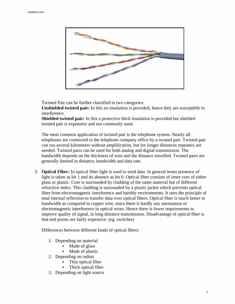
3. Satellite communication: Satellite acts as a switch in sky. On earth VSAT (Very Small Aperture Terminal) are used to transmit and receive data from satellite. Generally one station on earth transmits signal to satellite and it is received by many stations on earth. Satellite communication is generally used in those places where it is very difficult to obtain line of sight i.e. in highly irregular terrestrial regions. In terms of noise wireless media is not as good as the wired media. There are frequency band in wireless communication and two stations should not be allowed to transmit simultaneously in a frequency band. The most promising advantage of satellite is broadcasting. If satellites are used for point to point communication then they are expensive as compared to wired media.
Digital data to analog signals
Data Encoding
A modem (modulator-demodulator) converts digital data to analog signal. There are 3 ways to modulate a digital signal on an analog carrier signal.
mywbut.com
4
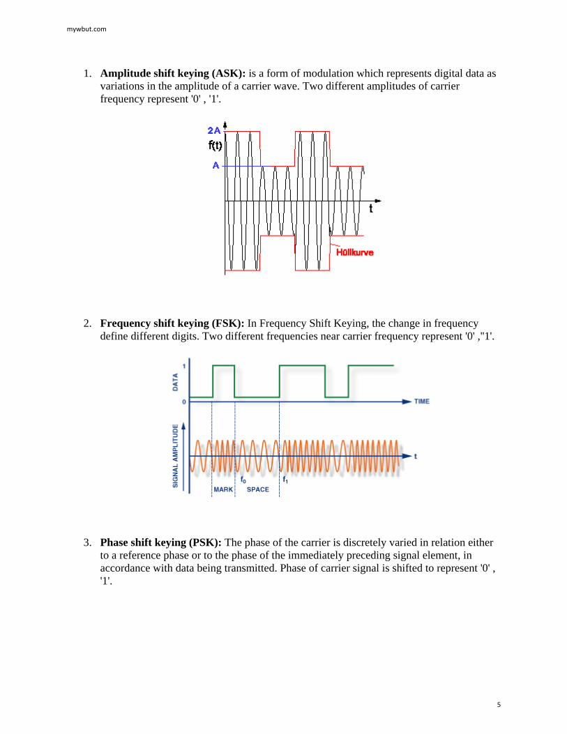
1. Amplitude shift keying (ASK): is a form of modulation which represents digital data as variations in the amplitude of a carrier wave. Two different amplitudes of carrier frequency represent '0' , '1'.
2. Frequency shift keying (FSK): In Frequency Shift Keying, the change in frequency define different digits. Two different frequencies near carrier frequency represent '0' ,''1'.
3. Phase shift keying (PSK): The phase of the carrier is discretely varied in relation either to a reference phase or to the phase of the immediately preceding signal element, in accordance with data being transmitted. Phase of carrier signal is shifted to represent '0' , '1'.
mywbut.com
5
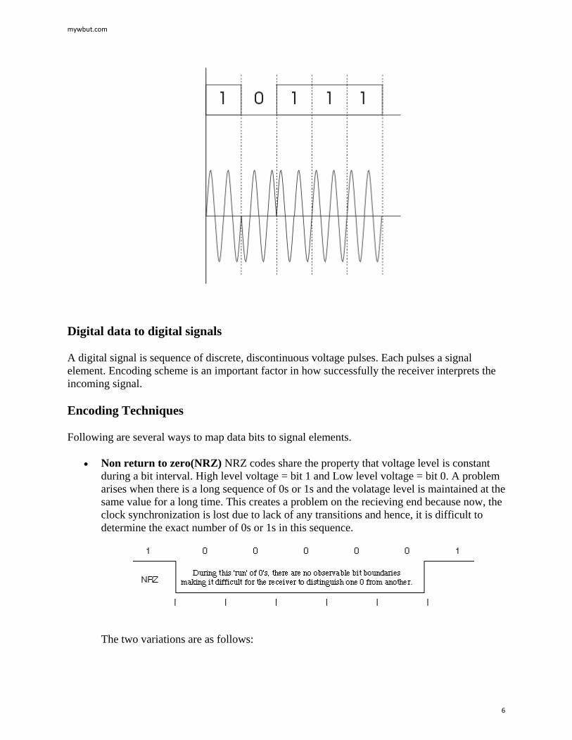
Digital data to digital signals
A digital signal is sequence of discrete, discontinuous voltage pulses. Each pulses a signal element. Encoding scheme is an important factor in how successfully the receiver interprets the incoming signal.
Encoding Techniques
Following are several ways to map data bits to signal elements.
• Non return to zero(NRZ) NRZ codes share the property that voltage level is constant during a bit interval. High level voltage = bit 1 and Low level voltage = bit 0. A problem arises when there is a long sequence of 0s or 1s and the volatage level is maintained at the same value for a long time. This creates a problem on the recieving end because now, the clock synchronization is lost due to lack of any transitions and hence, it is difficult to determine the exact number of 0s or 1s in this sequence.
The two variations are as follows:
mywbut.com
6
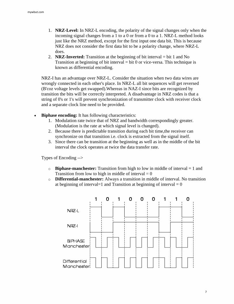
1. NRZ-Level: In NRZ-L encoding, the polarity of the signal changes only when the incoming signal changes from a 1 to a 0 or from a 0 to a 1. NRZ-L method looks just like the NRZ method, except for the first input one data bit. This is because NRZ does not consider the first data bit to be a polarity change, where NRZ-L does.
2. NRZ-Inverted: Transition at the beginning of bit interval = bit 1 and No Transition at beginning of bit interval = bit 0 or vice-versa. This technique is known as differential encoding.
NRZ-I has an advantage over NRZ-L. Consider the situation when two data wires are wrongly connected in each other's place. In NRZ-L all bit sequences will get reversed (B'coz voltage levels get swapped).Whereas in NAZ-I since bits are recognized by transition the bits will be correctly interpreted. A disadvantage in NRZ codes is that a string of 0's or 1's will prevent synchronization of transmitter clock with receiver clock and a separate clock line need to be provided.
• Biphase encoding: It has following characteristics: 1. Modulation rate twice that of NRZ and bandwidth correspondingly greater.
(Modulation is the rate at which signal level is changed). 2. Because there is predictable transition during each bit time,the receiver can
synchronize on that transition i.e. clock is extracted from the signal itself. 3. Since there can be transition at the beginning as well as in the middle of the bit
interval the clock operates at twice the data transfer rate.
Types of Encoding -->
o Biphase-manchester: Transition from high to low in middle of interval = 1 and Transition from low to high in middle of interval = 0
o Differential-manchester: Always a transition in middle of interval. No transition at beginning of interval=1 and Transition at beginning of interval = 0
mywbut.com
7
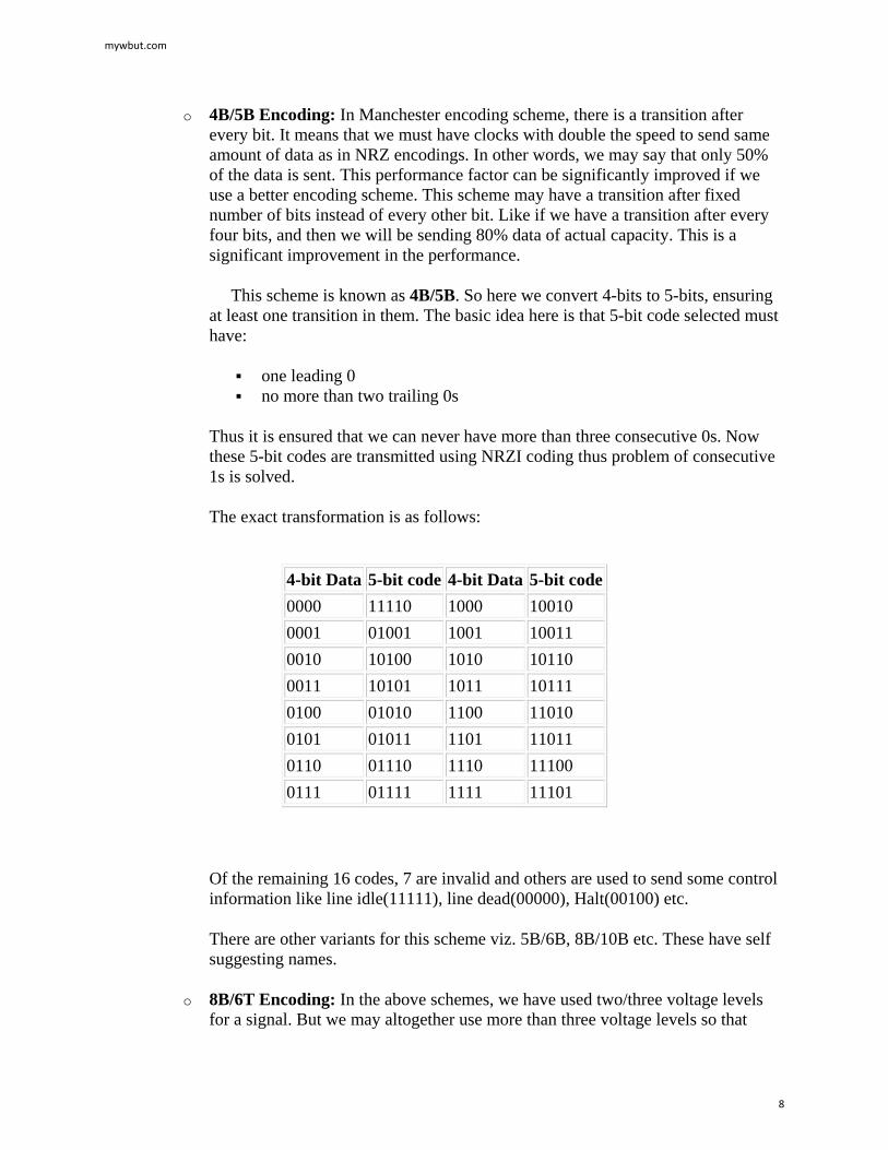
o 4B/5B Encoding: In Manchester encoding scheme, there is a transition after every bit. It means that we must have clocks with double the speed to send same amount of data as in NRZ encodings. In other words, we may say that only 50% of the data is sent. This performance factor can be significantly improved if we use a better encoding scheme. This scheme may have a transition after fixed number of bits instead of every other bit. Like if we have a transition after every four bits, and then we will be sending 80% data of actual capacity. This is a significant improvement in the performance.
This scheme is known as 4B/5B. So here we convert 4-bits to 5-bits, ensuring at least one transition in them. The basic idea here is that 5-bit code selected must have:
one leading 0 no more than two trailing 0s
Thus it is ensured that we can never have more than three consecutive 0s. Now these 5-bit codes are transmitted using NRZI coding thus problem of consecutive 1s is solved.
The exact transformation is as follows:
4-bit Data 5-bit code 4-bit Data 5-bit code 0000 11110 1000 10010 0001 01001 1001 10011 0010 10100 1010 10110 0011 10101 1011 10111 0100 01010 1100 11010 0101 01011 1101 11011 0110 01110 1110 11100 0111 01111 1111 11101
Of the remaining 16 codes, 7 are invalid and others are used to send some control information like line idle(11111), line dead(00000), Halt(00100) etc.
There are other variants for this scheme viz. 5B/6B, 8B/10B etc. These have self suggesting names.
o 8B/6T Encoding: In the above schemes, we have used two/three voltage levels for a signal. But we may altogether use more than three voltage levels so that
mywbut.com
8
more than one-bit could be send over a single signal. Like if we use six voltage levels and we use 8-bits then the scheme is called 8B/6T. Clearly here we have 729(3^6) combinations for signal and 256(2^8) combinations for bits.
Bipolar AIM: Here we have 3 voltage levels: middle, upper, lower o Representation 1: Middle level =0 Upper, Lower level =1 such that successive 1's
will be represented alternately on upper and lower levels. o Representation 2 (pseudo ternary): Middle level =1 Upper, Lower level=0
Analog data to digital signal:
The process is called digitization. Sampling frequency must be at least twice that of highest frequency present in the signal so that it may be fairly regenerated. Quantization - Max. and Min values of amplitude in the sample are noted. Depending on number of bits (say n) we use we divide the interval (min, max) into 2(^n) number of levels. The amplitude is then approximated to the nearest level by a 'n' bit integer. The digital signal thus consists of blocks of n bits. On reception the process is reversed to produce analog signal. But a lot of data can be lost if fewer bits are used or sampling frequency not so high.
• Pulse code modulation (PCM): Here intervals are equally spaced. 8 bit PCB uses 256 different levels of amplitude. In non-linear encoding levels may be unequally spaced.
• Delta Modulation (DM): Since successive samples do not differ very much we send the differences between previous and present sample. It requires fewer bits than in PCM.
Digital Data Communication Techniques:
For two devices linked by a transmission medium to exchange data , a high degree of co-operation is required. Typically data is transmitted one bit at a time. The timing (rate, duration, spacing) of these bits must be same for transmitter and receiver. There are two options for transmission of bits.
1. Parallel All bits of a byte are transferred simultaneously on separate parallel wires. Synchronization between multiple bits is required which becomes difficult over large distance. Gives large band width but expensive. Practical only for devices close to each other.
2. Serial Bits transferred serially one after other. Gives less bandwidth but cheaper. Suitable for transmission over long distances.
Transmission Techniques:
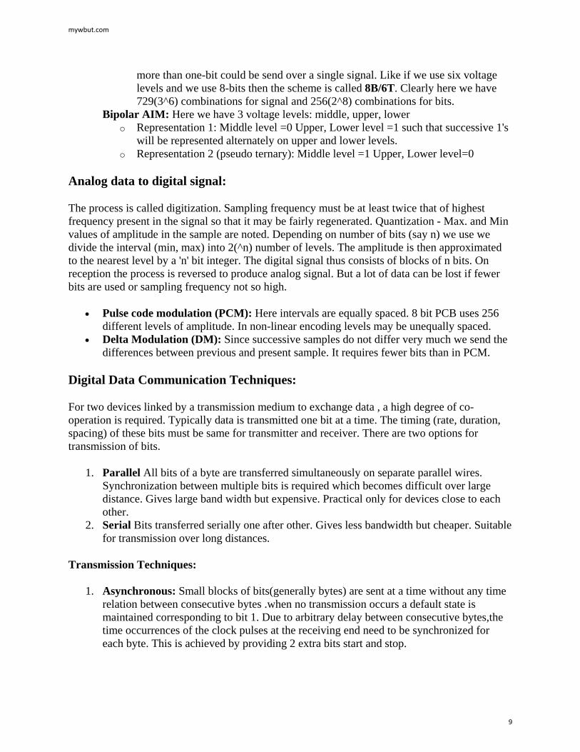
1. Asynchronous: Small blocks of bits(generally bytes) are sent at a time without any time relation between consecutive bytes .when no transmission occurs a default state is maintained corresponding to bit 1. Due to arbitrary delay between consecutive bytes,the time occurrences of the clock pulses at the receiving end need to be synchronized for each byte. This is achieved by providing 2 extra bits start and stop.
mywbut.com
9
Start bit: It is prefixed to each byte and equals 0. Thus it ensures a transition from 1 to 0 at onset of transmission of byte. The leading edge of start bit is used as a reference for generating clock pulses at required sampling instants. Thus each onset of a byte results in resynchronization of receiver clock.
Stop bit: To ensure that transition from 1 to 0 is always present at beginning of a byte it is necessary that default state be 1. But there may be two bytes one immediately following the other and if last bit of first byte is 0, transition from 1 to 0 will not occur. Therefore a stop bit is suffixed to each byte equaling 1. It's duration is usually 1,1.5,2 bits.
Asynchronous transmission is simple and cheap but requires an overhead of 3 bits i.e. for 7 bit code 2 (start, stop bits) +1 parity bit implying 30% overhead. However % can be reduced by sending larger blocks of data but then timing errors between receiver and sender can not be tolerated beyond [50/no. of bits in block] % (assuming sampling is done at middle of bit interval). It will not only result in incorrect sampling but also misaligned bit count i.e. a data bit can be mistaken for stop bit if receiver's clock is faster.
2. Synchronous - Larger blocks of bits are successfully transmitted. Blocks of data are either treated as sequence of bits or bytes. To prevent timing drift clocks at two ends need to be synchronized. This can done in two ways:
1. Provide a separate clock line between receiver and transmitter. OR 2. Clocking information is embedded in data signal i.e. biphase coding for digital
signals.
mywbut.com
10

Still another level of synchronization is required so that receiver determines beginning or end of block of data. Hence each block begins with a start code and ends with a stop code. These are in general same known as flag that is unique sequence of fixed no. of bits. In addition some control characters encompass data within these flags. Data + control information is called a frame. Since any arbitrary bit pattern can be transmitted there is no assurance that bit pattern for flag will not appear inside the frame thus destroying frame level synchronization. So to avoid this we use bit stuffing
Bit Stuffing: Suppose our flag bits are 01111110 (six 1's). So the transmitter will always insert an extra 0 bit after each occurrence of five 1's (except for flags). After detecting a starting flag the receiver monitors the bit stream. If pattern of five 1's appear, the sixth is examined and if it is 0 it is deleted else if it is 1 and next is 0 the combination is accepted as a flag. Similarly byte stuffing is used for byte oriented transmission. Here we use an escape sequence to prefix a byte similar to flag and 2 escape sequences if byte is itself a escape sequence.
Multiplexing
When two communicating nodes are connected through a media, it generally happens that bandwidth of media is several times greater than that of the communicating nodes. Transfer of a single signal at a time is both slow and expensive. The whole capacity of the link is not being utilized in this case. This link can be further exploited by sending several signals combined into one. This combining of signals into one is called multiplexing.
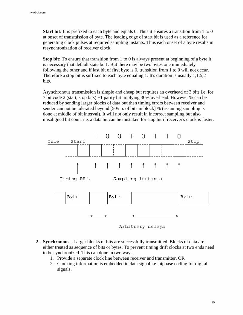
1. Frequency Division Multiplexing (FDM): This is possible in the case where transmission media has a bandwidth than the required bandwidth of signals to be transmitted. A number of signals can be transmitted at the same time. Each source is allotted a frequency range in which it can transfer it's signals, and a suitable frequency gap is given between two adjacent signals to avoid overlapping. This is type of multiplexing is commonly seen in the cable TV networks.
mywbut.com
11
2. Time Division Multiplexing (TDM): This is possible when data transmission rate of the media is much higher than that of the data rate of the source. Multiple signals can be transmitted if each signal is allowed to be transmitted for a definite amount of time. These time slots are so small that all transmissions appear to be in parallel.
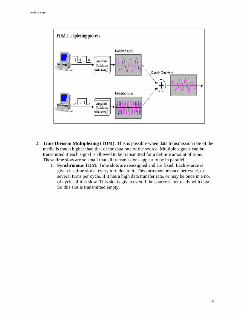
1. Synchronous TDM: Time slots are reassigned and are fixed. Each source is given it's time slot at every turn due to it. This turn may be once per cycle, or several turns per cycle, if it has a high data transfer rate, or may be once in a no. of cycles if it is slow. This slot is given even if the source is not ready with data. So this slot is transmitted empty.
mywbut.com
12
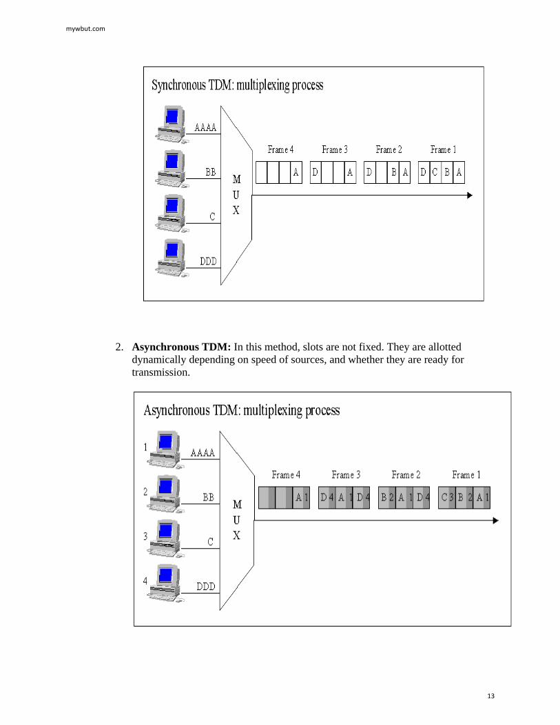
2. Asynchronous TDM: In this method, slots are not fixed. They are allotted dynamically depending on speed of sources, and whether they are ready for transmission.
mywbut.com
13
Network Topologies
A network topology is the basic design of a computer network. It is very much like a map of a road. It details how key network components such as nodes and links are interconnected. A network's topology is comparable to the blueprints of a new home in which components such as the electrical system, heating and air conditioning system and plumbing are integrated into the overall design. Taken from the Greek work "Topos" meaning "Place," Topology, in relation to networking, describes the configuration of the network; including the location of the workstations and wiring connections. Basically it provides a definition of the components of a Local Area Network (LAN). A topology, which is a pattern of interconnections among nodes, influences a network's cost and performance. There are three primary types of network topologies which refer to the physical and logical layout of the Network cabling. They are:
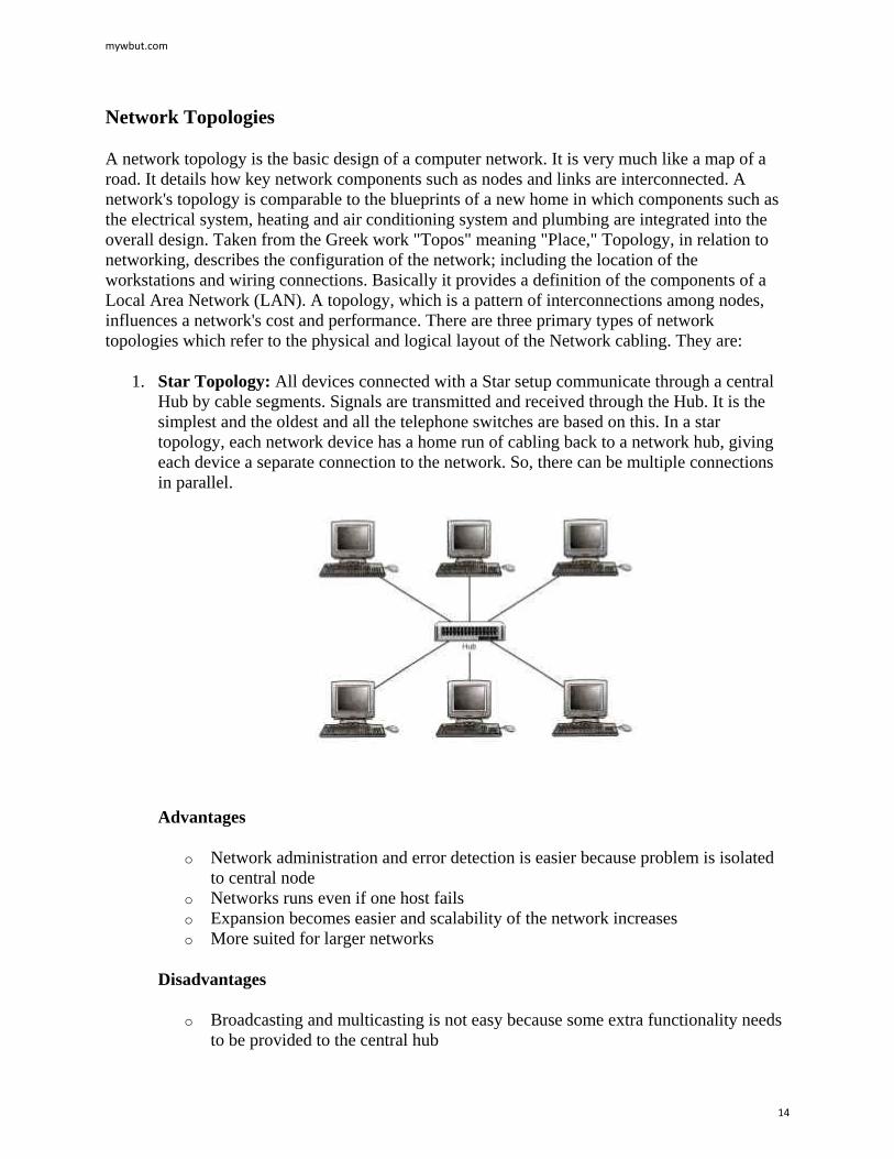
1. Star Topology: All devices connected with a Star setup communicate through a central Hub by cable segments. Signals are transmitted and received through the Hub. It is the simplest and the oldest and all the telephone switches are based on this. In a star topology, each network device has a home run of cabling back to a network hub, giving each device a separate connection to the network. So, there can be multiple connections in parallel.
Advantages
o Network administration and error detection is easier because problem is isolated to central node
o Networks runs even if one host fails o Expansion becomes easier and scalability of the network increases o More suited for larger networks
Disadvantages
o Broadcasting and multicasting is not easy because some extra functionality needs to be provided to the central hub
mywbut.com
14
o If the central node fails, the whole network goes down; thus making the switch some kind of a bottleneck
o Installation costs are high because each node needs to be connected to the central switch
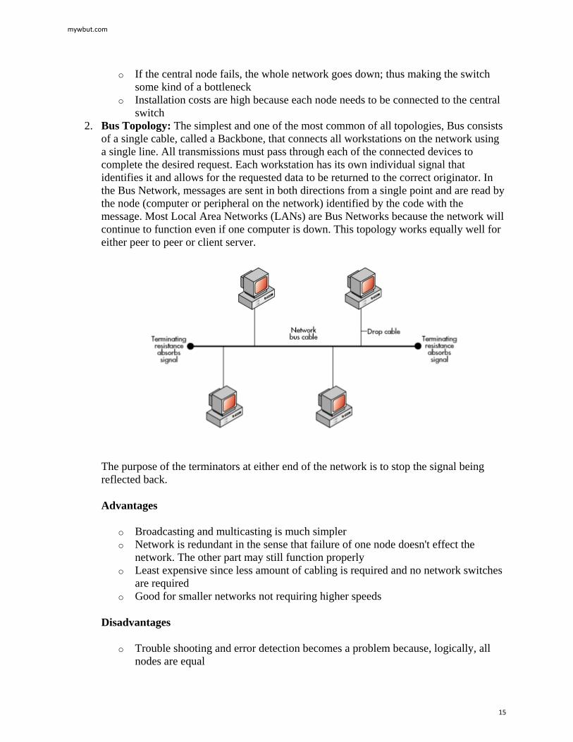
2. Bus Topology: The simplest and one of the most common of all topologies, Bus consists of a single cable, called a Backbone, that connects all workstations on the network using a single line. All transmissions must pass through each of the connected devices to complete the desired request. Each workstation has its own individual signal that identifies it and allows for the requested data to be returned to the correct originator. In the Bus Network, messages are sent in both directions from a single point and are read by the node (computer or peripheral on the network) identified by the code with the message. Most Local Area Networks (LANs) are Bus Networks because the network will continue to function even if one computer is down. This topology works equally well for either peer to peer or client server.
The purpose of the terminators at either end of the network is to stop the signal being reflected back.
Advantages
o Broadcasting and multicasting is much simpler o Network is redundant in the sense that failure of one node doesn't effect the
network. The other part may still function properly o Least expensive since less amount of cabling is required and no network switches
are required o Good for smaller networks not requiring higher speeds
Disadvantages
o Trouble shooting and error detection becomes a problem because, logically, all nodes are equal
mywbut.com
15
o Less secure because sniffing is easier o Limited in size and speed
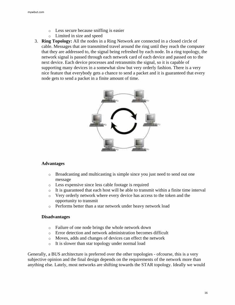
3. Ring Topology: All the nodes in a Ring Network are connected in a closed circle of cable. Messages that are transmitted travel around the ring until they reach the computer that they are addressed to, the signal being refreshed by each node. In a ring topology, the network signal is passed through each network card of each device and passed on to the next device. Each device processes and retransmits the signal, so it is capable of supporting many devices in a somewhat slow but very orderly fashion. There is a very nice feature that everybody gets a chance to send a packet and it is guaranteed that every node gets to send a packet in a finite amount of time.
Advantages
o Broadcasting and multicasting is simple since you just need to send out one message
o Less expensive since less cable footage is required o It is guaranteed that each host will be able to transmit within a finite time interval o Very orderly network where every device has access to the token and the
opportunity to transmit o Performs better than a star network under heavy network load
Disadvantages
o Failure of one node brings the whole network down o Error detection and network administration becomes difficult o Moves, adds and changes of devices can effect the network o It is slower than star topology under normal load
Generally, a BUS architecture is preferred over the other topologies - ofcourse, this is a very subjective opinion and the final design depends on the requirements of the network more than anything else. Lately, most networks are shifting towards the STAR topology. Ideally we would
mywbut.com
16
like to design networks, which physically resemble the STAR topology, but behave like BUS or RING topology.
mywbut.com
17